Embed Size (px)
Citation preview

Division 10
Specialties Page No.'s Section 10A - Movable Metal Partition 10A-1 to 4
Section 10B - Metal Toilet Enclosures & Partitions 10B-1 to 8
Section 10C - Toilet Room Accessories 10C-1 to 4
Section 10D - Metal Lockers 10D-1 to 6
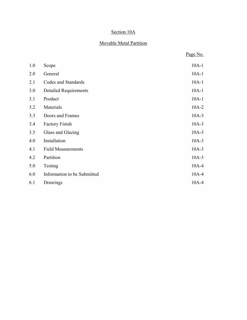
Section 10A
Movable Metal Partition Page No. 1.0 Scope 10A-1
2.0 General 10A-1
2.1 Codes and Standards 10A-1
3.0 Detailed Requirements 10A-1
3.1 Product 10A-1
3.2 Materials 10A-2
3.3 Doors and Frames 10A-3
3.4 Factory Finish 10A-3
3.5 Glass and Glazing 10A-3
4.0 Installation 10A-3
4.1 Field Measurements 10A-3
4.2 Partition 10A-3
5.0 Testing 10A-4
6.0 Information to be Submitted 10A-4
6.1 Drawings 10A-4

10A-1
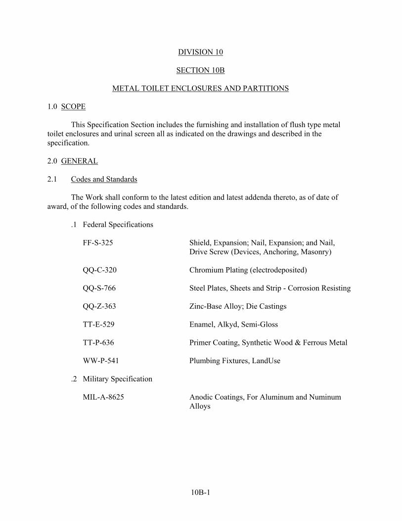
DIVISION 10
SECTION 10A
MOVABLE-METAL PARTITION 1.0 SCOPE This Specification Section includes the furnishing and installation of a movable steel partition all as indicated on the drawings and described in the specification. 2.0 GENERAL 2.1 Codes and Standards The Work shall conform to the latest edition and latest add nda thereto, as of date of award, of the following codes and standards.
.1 Federal Specification QQ-S-698 Steel, Sheet and Strip, Low Carbon FF-B-571 Bolts; Nuts; Studs; and Tap-Rivets (and material for same) TTE-491 Enamel; Gloss; Synthetic; (for metal and wood hospital furniture) TT-P-659 Primer-Surfacer; Synthetic; Tints and White (for metal and Wood Furniture)
3.0 DETAILED REQUIREMENTS 3.1 Product The partition furnished under this section of the specifications shall be the product of a manufacturer regularly engaged in the manufacture of steel movable partitions.

10A-2
3.2 Materials 3.2.1 Panels
Panel units shall be flush 2-4" thick, mineral wool insulated, factory assembled into complete units. Panel faces shall be 20 ga. roller-leveled steel with horizontal reinforcements welded to back -face of panel to assure uniform thickness and flatness.
Top and bottom of panel faces shall be formed with right angle returns to engage top and
bottom channels eliminating raw edges. Lower panel shall be 3'-6" above base and shall have top edge formed to receive glass.
Panel units shall be locked together by linkage clips wedged and precision fit to the
posts. The linkage and posts shall be concealed by a recessed steel accent trim providing a light and sound seal. 3.2.2 Base
Base shall be 18 ga. steel, 3-3/4" nominal height, recessed 4" behind panel face, and adjustable to floor irregularities. Base shall install individually from each side of partition to allow continuous wiring and be attached at the top by a continuous steel member, spring activated to hold base member to bottom panel edge. Floor channel shall be designed to provide for a continuous light and sound seal at the floor. 3.2.3 Cornice
Cornice shall be 18 ga. steel 2-4" high 3-4" wide to provide lateral stapility. Corners shall be mitred, welded and ground smooth. Each cornice field joint shall have a concealed steel pull-up splice to maintain structural rigidity and to provide perfect vertical and horizontal alignment. 3.2.4 Partition End Fillers
Partition end fillers shall be double 20 ga. sheets mineral wool insulated. End fillers shall join adjacent posts in the same way as panel units and shall fit neatly into a channel securely fastened to a fixed building wall.

10A-3
3.3 Doors and Frames
Doors shall be flush steel and. glass 1-3/4" thick with 3/32" clearance at jambs and at head. Doors shall be manufacturer's standard 7'-0" high, 18 ga. steel, with edge lock joints. Steel and glass doors shall be glazed in a manner similar to panel units without use of screws. Door frames shall be cold rolled 18 ga. steel, with a slipfit adjustment at the head to compensate for floor irregularities. Door frames shall have a continuous cushioned sound sealed stop at head as well as at hinge and stike jambs. Frames and doors shall be mortised and reinforced as required to receive hardware specified in Section 8B, Builders' Hardware (Interior) of this Specification. Hardware shall be installed by partition manufacturer. 3.4 Factory Finish
All exposed surfaces shall be properly cleaned and completely free of oil or dirt deposits prior to painting. Immediately after cleaning, the surfaces shall be completely covered with a rust inhibitive primer and undercoat. Final coats of baking enamel color and gloss as selected by Engineer shall then be applied and all coats shall be thoroughly baked for maximum adhesion, hardness and resistance to abrasion. 3.5 Glass and Glazing
Glass and glazing for door and partition shall be as specified in Section 8C, GLASS and GLAZING (Interior) of the specifications. 4.0 INSTALLATION 4.1 Field Measurements
Prior to fabrication, Contractor shall verify all conditions at the building site for dimensions, fitting, and attachment of all items directly connected with the movable steel partition specified herein. 4.2 Partition
Partition shall be installed on top of finished flooring. Partitions shall be neatly fitted to building

10A-4
Conditions within design tolerances, erected in a rigid and substantial manner straight and plumb with horizontal lines level. All fasteners shall be concealed. Hardware shall be adjusted and left in proper working condition. All finished surfaces shall be free of tool marks, abrasions and scratches. 5.0 TESTING
No additional tests beyond those normally employed either in manufacturing, installation or construction processes or as called for by the specified codes and standards are required under this Article. 6.0 INFORMATION TO BE SUBMITTED
The following information and data shall be submitted 30 days after award of contract. 6.1 Drawings
Drawings for all items specified herein shall be submitted for approval. The drawings shall show dimensions and details of construction, installation and relation to adjoining and related work which will require cutting or close fitting and shall show reinforcement, anchorage and other work required for complete installation.

Section 10B
Metal Toilet Enclosures and Partitions Page No. 1.0 Scope 10B-1 2.0 General 10B-1 2.1 Codes and Standards 10B-1 3.0 Detailed Requirements 10B-2 3.1 Materials 10B-2 3.2 Dimensions 10B-4 3.3 Hardware 10B-5 3.4 Urinal Screen 10B-6 3.5 Finish 10B-7 4.0 Installation 10B-7 5.0 Testing 10B-8 6.0 Information to be Submitted 10B-8 6.1 Drawings 10B-8
10B-1
DIVISION 10
SECTION 10B
METAL TOILET ENCLOSURES AND PARTITIONS 1.0 SCOPE
This Specification Section includes the furnishing and installation of flush type metal toilet enclosures and urinal screen all as indicated on the drawings and described in the specification. 2.0 GENERAL 2.1 Codes and Standards
The Work shall conform to the latest edition and latest addenda thereto, as of date of award, of the following codes and standards.
.1 Federal Specifications FF-S-325 Shield, Expansion; Nail, Expansion; and Nail, Drive Screw (Devices, Anchoring, Masonry) QQ-C-320 Chromium Plating (electrodeposited) QQ-S-766 Steel Plates, Sheets and Strip - Corrosion Resisting QQ-Z-363 Zinc-Base Alloy; Die Castings TT-E-529 Enamel, Alkyd, Semi-Gloss TT-P-636 Primer Coating, Synthetic Wood & Ferrous Metal WW-P-541 Plumbing Fixtures, LandUse .2 Military Specification MIL-A-8625 Anodic Coatings, For Aluminum and Numinum Alloys

10B-2
3.0 DETAILED REQUIREMENTS 3.1 Materials 3.1.1 Type and Quality The partitions and end panels, pilaster fronts and doors shall be of the flush type, constructed of metal with sound-deadening paperboard cores. The pilaster fronts shall be as shown on the drawings. The work shall include all fastenings, fittings and hardware for a complete installation. 3.1.2 Steel Sheets Steel sheets for face plates of panels, pilasters and doors shall be cold-rolled galvanized, bonderized, stretcher-leveled, furniture-stock steel. Strips for edge binding shall be galvanized steel suitable for die-drawing without fracturing the coating. The following thicknesses, expressed in manufacturer's standard gage before zinc-coating and fabrication, are the minimum which will be acceptable. Face plates of doors, 22 gage; face plates of enclosure partitions, edge locking strips of doors, partitions and all edge facing strips, 20 gage; edge locking strip of floor-supported pilasters, 18 gage; face plates of floor-supported pilasters, 16 gage; concealed hooks and reinforcement for tapping, 14 gage, concealed reinforcement for anchoring devices, 12 gage. 3.1.3 Cores Cores of doors, panels and pilasters shall consist of compressed, lightweight, corrugated paperboard material or heavy-paper honeycomb, flanged or faced on both sides with heavy kraft paper. The finished core shall be cemented to face panels. The cores for doors and partitions shall be full 1 inch thick, and the cores for pilasters shall be 1-/ inch nominal thickness. 3.1.4 Construction Panels, pilasters and doors shall be constructed of 2 face plates, with formed edges, assembled over and cemented under pressure to the sound-deadening core. The formed edges shall be bound and locked with die-drawn slip-lock binding strips or by welds concealed by slip-lock edge facing strips.
10B-3
The edge strips shall hold the plates with a tension grip, conceal all holes required for fabrication and all cut metal edges, and be mitered and welded at corners with welds ground smooth. The doors shall have reinforced cutouts for hinges and be further strengthened by internal brazing or welding of the locking strips to the formed edges halfway in elevation on each side. Doors and panels shall finish uniformly 1 inch thick; pilasters shall finish uniformly 1-4 inches thick, with a plus or minus tolerance of 1/32 inch in both cases. Surfaces shall be smooth and free from wave, warp and buckle. Where machine screws are specified for fastenings, the panels, pilasters and doors shall have concealed tapped reinforcement or rivet nuts with gaskets for the attachment of hardware and accessories. Panels shall be fastened to pilasters at not less than 3 points in a manner that will insure a permanently tight tension grip. The fastening shall be by hooks in shear built into the contact edge of the panel, which shall be inserted into vertical openings in the pilaster and forced downward to draw the pilaster and panel together with a tension grip. The assembly shall be secured against loosening and torsion by a wing bracket through-bolted to the panel with sex bolts and fastened on the inside of the pilaster with similarly finished machine screws, or the panels may be anchored to pilasters by two stirrup brackets, each through-bolted to the partition with a sex bolt and fastened to pilaster with 2 machine screws providing 2 inch clearance between the edge of the panel and the face of the pilaster. 3.1.5 Pilaster Bases Pilaster bases shall be not less than 3 inches high of 0.040 inch thick wrought brass, polished, nickel-plated and finished in polished chromium plate, or of 0.031 inch thick corrosion-resisting steel containing at least 18 percent chromium and 8 percent nickel with electropolished finish. Bases shall be secured in place with screws or concealed clips. Stainless steel finish shall be No. 4. 3.1.6 Brackets Wall and stirrup brackets shall be extruded brightpolish-finish anodic - coated aluminum, chromium-plated brass, or die-cast zinc alloy that is either chromium plated or given a baked-enamel finish coat to match the partition finish. Brackets shall have clamp flanges fastened to the panels with 3/16 inch chromium finished brass sex bolts.

10B-4
Each wall bracket shall be anchored to the wall with two a inch bolts of a type appropriate to the type of wall construction into which they must be fastened. Bolt heads shall be brush-painted with suitable enamel after erection. The anodic coating shall conform to Military Specification MIL-A-8625, Type II. Chromium plating shall conform to Federal Specification QQ-C-320, Class I, Type I. 3.1.7 Support and Anchorage of Pilasters Floor-mounted pilasters shall be supported independently of the finished floor and shall be fastened to the structural slab by means of a built-in, welded anchoring device designed to transmit the strains of lateral thrust and pull to the structure through two 3/8 inch minimum diameter cadmium-plated stud bolts secured into approved expansion anchorage units having a penetration of not less than 2 inches into structural concrete. Pilasters with wall supports shall have one such stud bolt near the edge that adjoins the door. The anchoring devices shall be readily accessible for leveling, plumbing, and tightening the enclosure installations and shall be concealed by the pilaster base hereinbefore specified. 3.2 Dimensions Toilet enclosures shall be arranged as indicated. Dimensions based on 2-foot-l0-inch centering of partitions shall be approximately as follows:
Partition Panels Floor Mounted Enclosure depth 4 feet 8 inches Height 4 feet 6 inches Floor clearance 1 foot 2 inches Pilasters Height 5 feet 8 inches Floor clearance Width Wall End 2 inches Intermediate 9 inches

10B-5
Doors Height 4 feet 6 inches Width 2 feet
Room-entrance screens shall be of the dimensions indicated on drawings. 3.3 Hardware Enclosure doors shall swing in, and each closure shall be fitted with hinges, a throw latch, a combination stop and keeper and a combination hook and bumper. Hardware and fastenings shall be plain, heavy-pattern, of aluminum zinc-alloy, corrosion-resisting steel or wrought, extruded or cast brass. Exposed surfaces of hardware and fastenings shall be finished as follows: brass and zincalloy shall have a chromium-plated finish conforming to Federal Specification QQ-C-320, Class 1, Type I; aluminum shall be satin finish or shall have an anodic-coating conforming to Military Specification MIL-A-8625, Type II, and corrosion-resisting steel shall have a No. 4 finish. Hinges, stops and combinations stops and keepers shall have clamp flanges to transmit any strains of door-closing to the pilasters and shall be applied with 3/16 inch sex bolts. Surface applied hardware shall be applied with machine screws. Sex bolts and machine screws shall have one-way right-hand heads or spanner heads. If spanner heads are provided, two tools for their removal shall be supplied. Hinges shall be of the spring-tension, gravity or torsion-bar type and shall be adjustable, enabling the door to be brought to rest in any position. On enclosure doors, the hinges shall be adjusted to hold the door open at 30 degrees. The lower hinge shall be encased or concealed within the door and shall have either a concealed ball-bearing roller operating on a corrosion-resisting steel cam or two mating nylon-resin cams aligned by a heavy corrosion-resisting steel pin. The upper hinge shall have a pivot pin secured above and below the point of bearing with the bearing concealed in a supporting member placed in a cutout near the top of the door. Top pivots of gravity-actuated hinges shall be designed to accommodate the vertical movement of

10B-6
the door. Pivot guide pins and ball-bearing rollers shall be of hardened corrosion-resisting steel. All moving parts shall operate in nylon bearings or graphite-bronze, self-oiling, needle or thrust frictionless bearings. Nonoperating, supporting, or encasing members may be die-cast zinc alloy.
The upper and lower hinges shall consist of an arrangement which provide a torsion bar attached to oilimpregnated copper-base-alloy bearings operating in corrosionresisting steel bushings, the working parts encased or concealed within the door. Upper and lower brackets shall be of die-cast zinc alloy or other non-ferrous alloy, and of such design that no part of the hinge assembly will extend above or below the door lines.
Latch shall be either the sliding or throw type, as standard with the manufacturer, and
may be either brass or corrosion-resisting steel. The latch shall be mounted on the door midway between the top and bottom edges.
Combination stop and keeper shall be fitted with a rubber bumper and shall be mounted
on the pilaster at a point opposite the latch. Combination hook and bumper shall have a minimum projection of 3 inches and a base
not less than 1-2 inches in diameter. The hook and bumper shall be mounted approximately 3 inches from the top edge and 6 inches from the swing edge of the door.
Toilet paper holders shall conform to Federal Specification WW-P-541, Type 437. Two
toilet paper holders shall be installed for each water closet so that the center of the first fixture is located 2 feet, 4 inches from the rear wall with the second fixture set adjacent to the first fixture in the direction of the door. The top of each fixture shall be 3 feet above the floor. Each brace of fixtures shall be mounted back to back on the partition wherever possible. 3.4 Urinal Screen Urinal screen shall be wall-hung flush type, 42 by 24 by 1-4 inches, fabricated of not thinner than 20 gage cold-rolled galvanized, bonderized, stretcher-leveled, furniture-stock steel faceplates over core as specified for

10B-7
toilet enclosures; except that the 4 inches of the panel abutting the wall shall have concealed reinforcement from the top to the bottom of the screen. _The reinforcement shall be 4 by 4 inch angles of not lighter than 11 gage steel or other equivalent steel shape continuously welded to the backs of the faceplates. The screen shall be fastened to the wall by four bolts on each side of the screen through the reinforcing angle flange, using 4 inch toggle bolts. Urinal screen shall be painted in same manner and color as specified for toilet enclosures. 3.5 Finish All exposed metal surfaces not specified to be aluminum, corrosion-resisting steel or chromium-plated shall be thoroughly cleaned and factory finished by spraying with one coat of a properly formulated synthetic primer followed by one coat of low-gloss synthetic enamel and then ovenbaked at a temperature in excess of 275 degrees F for the length of time necessary to cause polymerization at the temperature employed. 4.0 INSTALLATION The material shall be erected in a rigid and substantial manner, straight and plumb, with all horizontal lines level. Partition and end panels shall be installed with a clearance of approximately 1 inch at walls. Wallend pilasters shall be installed with a clearance for cove base. Panels and pilasters shall be fastened to walls with brackets located near top and bottom, preferably at joints in tile or other wall finish. Doors shall be out of wind. The clearance of vertical edges of doors shall be uniform from top to bottom and shall not exceed 3/16 inch. Hardware shall be adjusted for perfect working order. Units or sections that are dented, punctured, deeply scratched to metal, or otherwise damaged shall be removed and replaced with new undamaged units or sections. Units having only marred, abraded, or lightly scratched surface finish shall be refinished in an adequately equipped paint shop. Refinishing shall include filling and sanding the damaged areas and spray painting with an air-drying enamel. The refinished surface shall be of the same texture and shade as the adjacent undisturbed finish. After all other work in the area including painting, is completed, all exposed surfaces of the partitions and fittings shall be cleaned.

10B-8
5.0 TESTING No additional tests beyond those normally employed either in manufacturing installation or construction processes or as called for by the specified codes are required under this Article. 6.0 INFORMATION TO BE SUBMITTED The following information shall be submitted 30 days after award of contract. 6.1 Drawings Drawings shall be submitted for Engineer's approval. The drawings shall show plans, elevations, details of construction, gages of metal, hardware, fittings and fastenings. Material shall not be delivered to the jobsite before the approved drawings have been returned to Contractor.
The drawings shall be accompanied by descriptive data and standard color charts in triplicate and a sample piece of the sheet metal not less than 3 by 5 inches in size. The sample shall show the rust-proofed surface of the base metal on one side and the prime coat and the finish coat of enamel on the other side.

Section 10C
Toilet Room Accessories Page No. 1.0 Scope 10C-1
2.0 General 10C-1
2.1 Codes and Standards 10C-1
3.0 Detailed Requirements 10C-1
3.1 Materials 10C-1
4.0 Installation 10C-3
4.1 Delivery Storage and Handling 10C-3
4.2 Accessories 10C-3
4.3 Acceptance 10C-3
5.0 Testing 10C-3
6.0 Information to be Submitted 10C-4
6.1 Drawings 10C-4

10C-1
DIVISION 10
SECTION 10C
TOILET ROOM ACCESSORIES 1.0 SCOPE This Specification Section includes the furnishing and installation of Toilet Room accessories-all.as indicated on the drawings and described in the specification. 2.0 GENERAL 2.1 Codes and Standards The Work shall conform to the latest edition and latest addenda thereto, as of date of award, of the following codes and standards.
.1 Federal Specifications DD-M-411 Mirrors; Plate Glass, Framed FF-D-396 Dispensers; Soap QQ-C-320 Chromium Plating (Electro Deposited) .2 National Association of Architectural Metal Manufacturers Finish Manual
3.0 DETAILED REQUIREMENTS 3.1 Materials For material, finish workmanship and quality identification purposes, Charles Parker Company, Meriden Connecticut catalog numbers appear in the specification. Accessories manufactured by other manufacturer's may be substituted. All items to be furnished and installed under this specification shall be subject to acceptance and approval by Engineer. 3.1.1 Mirror & Shelf Combination In Mens Toilet furnish and install a 26 inch by 24 inch Model 53020 mirror and shelf combination.

10C-2
Mirror glass shall be No. 1 quality, 1/4 inch polished plate glass with backs silvered two coats, heavily electroplated with copper and given a prime coat of mirror backing paint. Mirror shall be guaranteed against silver spoilage for a period of five years from the date of installation.
Frames shall be 3/8 inch by 5/8 inch stainless steel angle, 20 gauge, Type 302 (18-8) in
satin finish. Corrosion resistant steel back shall be attached to frame with concealed screws to completely enclose mirror assembly.
To the back of mirror backing metal plate attach a minimum of 4 clips which shall
engage an "H" hanger which shall be fastened to the wall. Shelf shall be 5 inches wide, 22 gauge type 302 stainless steel (18-8) satin finish with
concealed stainless steel brackets. Shelf shall be full length of mirror. 3.1.2 Surface Mounted - Combination Towel, Mirror, Soap Dispenser and Shelf In Mens and Womens Toilet Room furnish and install complete over lavatory 'a surface mounted combination towel, mirror soap dispenser and shelf with a seamless skirt. Model number 614. The overall dimensions shall be 17 3/16 inches by 30 5/8 inches by 4 inches. Construction shall be of 22 gauge, Type 302 (18-8) satin finish stainless steel, one piece seamless construction flange and shelf with retaining edges. A continuous 4 inch deep skirt to match unit shall be provided for fully surface mounted installation. Door shall have full length piano hinge and tumbler lock, a 1/4 inch polished plate glass mirror shall be fastened to face of door with a satin finish stainless steel frame. Mirror glass shall be polished plate glass with backs silvered two coats, heavily electroplated with copper and given a prime coat of mirror backing paint. Mirror shall be guaranteed against silver spoilage for a period of five years. 3.1.3 Mop Holder Mop holder shall be furnished and installed in Janitors closet. Mop holder shall be Model No. 608, "Mop Holder on Strip" and shall be 36 inches long with (4) holders and shall be Type 302 (18-8) stainless steel, No. 4 satin

10C-3
finish. Mounting strip shall be mounted to masonry wall using stainless steel fasteners. 4.0 INSTALLATION 4.1 Delivery Storage and Handling Toilet Room accessories shall be delivered, stored and handled so as not to be damaged or deformed. Units or sections that are dented, punctured, deeply scratched or otherwise damaged shall be removed and replaced with new undamaged units or sections. 4.2 Accessories Accessories that are to be surface mounted shall have mounting holes carefully drilled so as not to damage the finished wall. All vertical surfaces shall be installed plumb and all horizontal surfaces level in locations as designated on drawings. Fasteners shall be as furnished and as recommended by the manufacturer. Exposed fasteners shall be chrome plated or stainless steel. 4.3 Acceptance Before acceptance, accessories shall be securely installed where shown on drawings, all operating mechanism operating properly, and finished surfaces left clean and free of blemishes. 5.0 TESTING No additional tests beyond those normally employed either in manufacturing, installation or construction processes or as called for by the specified codes and standards are required under this Article.

10C-4
6.0 INFORMATION TO BE SUBMITTED The following information and data shall be submitted 30 days after award of contract. 6.1 Drawings Drawings shall be submitted for Engineer's approval. The drawings shall indicate complete details of construction including gauges of metal, anchors, fittings and fastenings. Material shall not be delivered to the jobsite before the approved drawings have been returned to Contractor.

Section 10D
Metal Lockers Page No. 1.0 Scope 10D-1
2.0 General 10D-1
2.1 Codes and Standards 10D-1
3.0 Detailed Requirements 10D-1
3.1 Description 10D-1
3.2 Materials 10D-2
3.3 Finishes 10D-4
4.0 Installation 10D-5
4.1 Field Measurements 10D-5
4.2 Assembly 10D-5
4.3 Acceptance 10D-5
5.0 Testing 10D-5
6.0 Information to be Submitted 10D-6
6.1 Sample 10D-6

10D-1
DIVISION 10
SECTION 10D
METAL LOCKERS
1.0 SCOPE This Specification includes the furnishing and installation of all metal lockers and benches all as indicated on the drawings and described in the specification. 2.0 GENERAL 2.1 Codes and Standards The Work shall conform to the latest edition and latest addenda thereto, as of date of award, of the following codes and standards.
.1 Federal Specifications AA-L-486 Locker, Clothing, Steel TT-C-490 Cleaning Methods and Pretreatment of Ferrous Surfaces for Organic Coatings. TT-E-529 Enamel, Alkyd, Semigloss TT-P-636 Primer Coating, Alkyd, Wood & Ferrous Metal
3.0 DETAILED REQUIREMENTS 3.1 Description Lockers shall be single tier lockers, semi-louvered door, closed base, sloping top. Size 12 inches wide by 15 inches deep by 78 inches high including base. All lockers shall be of the same type and size, with all parts and assemblies identical.

10D-2
3.2 Materials 3.2.1 Body Body of Lockers shall be cold-rolled mild annealed, high grade steel, free from surface imperfections, of a quality normally used in high-grade commercial clothing lockers. Steel shall be 24 gauge reinforced or flanged to give double thickness of metal at back vertical corners and shall be used for sides, backs, tops, bottoms, shelf and other structural parts. Bolts shall be cadmium plated. Spacing of bolts in body construction shall not exceed 9 inches on centers. 3.2.2 Doors and Frames Doors shall be one piece No. 16 gauge suitably flanged on all four edges to provide adequate strength and stiffness. All doors shall have channel shaped reinforcement on vertical edges. Provide banks of six ventilating louvers at top and bottom of doors. Door jambs shall consist of three members welded to door frames to engage locking device, designed to prevent freeing of locking device by prying. Each jamb member shall have easily replaced soft rubber silencer. 3.2.3 Hardware
All hardware items except hinges and handles when constructed of ferrous metal, shall have a protective electrodeposited coating of zinc or cadmium.
Handles shall be non-recessed type and shall be diecast of zinc alloy, chromium plated,
having a tensile strength of not less than 40,000 psi. Hinges shall be full loop, tight pin five knuckle, 050 inch steel, 2 inch high, projection
welded to door frame and securely fastened to the door. Hinge pin to be spun over at ends to prevent removal. Each locker door shall have 3 hinges and shall permit door to open 180 degrees.
Hooks shall have ball ends and shall be either malleable cast iron, zinc alloy, or formed
from steel. Each locker shall have 3 single prong hooks, below hat shelves and one double prong hook attached to hat shelf.

10D-3
Hat shelf, one per locker, shall be located approximately 9 inches below top. Shelf shall be flanged on sides and back-channel formation on front flange.
Latching mechanism shall be the prelocking type which permits door to be locked in
open position and closed without unlocking the lock. Latch finger shall retain not less than 4 inch of the locking bar bolt at three points when door is fully closed and locked. Locking bar for each door shall be channel-shaped steel of not less than 18 gauge, shall be fully or partially enclosed and mounted inside door on the vertical latching edge. Latching mechanism shall be controlled by door handle or lock-bar activator.
Live rubber bumpers or silencers shall be furnished at points of contact on top and
bottom of door jamb or an equivalent method of silencing shall be employed. Bumpers shall be mounted securely but readily removable when replacement is necessary.
Each locker shall be equipped with a built-in flat key lock. Locks shall be of different
key changes and master keyed. Furnish two flat steel keys with each lock, having corresponding locker numbers stamped on each key. Provide six master keys. Locks shall be made of zinc coated steel and have the following characteristics:
Case 1-1/2" x 1-5/8 (approximately) with ears top and bottom for attaching. Backset, 7/8" (approximately) Dead bolt, brass or die-cast zinc alloy. Tumblers, three to five secured levers, or five disc tumblers. Each locker shall be supplied with polished aluminum number plate, 2-4 inches wide by
1 inch high, with black etched numerals not less than 3/8 inch high.. Plates shall be attached to front of door with split rivets. The numbering system shall be as determined by Engineer. 3.2.4 Louvers Louvers for lockers shall have two sets centrally located widthwise; one set near the top and one set near the

10D-4
bottom with not less than 6 nor more than 9 louvers in each set. 3.2.5 Locker Benches Tops shall be edge grain, clear maple or birch, approximately 9-2 inches wide by 1-4 inches thick by required lengths, laminated from strips of over 3 inches wide, supported on metal standards or pedestals. Standards or pedestals shall be stock steel pipe standards or steel pedestals, providing firm support and spaced not more than 4 feet on centers. Overall height of standards or pedestals shall be approximately 17 inches. Standards or pedestals shall be attached to seat with screws and anchored to floor with expansion bolts. Standards or pedestals shall have corrosion resisting prime coat and enamel to match lockers. Seats shall be finished with one coat shellac, one coat paste filler, and two coats of spar varnish, or approved equal. 3.3 Finishes 3.3.1 Surface Preparation All parts shall be thoroughly cleaned before painting and given a bonding and rust-resisting undercoat. Finish shall be baked enamel providing a tough, durable finish. Color shall be as selected by Engineer. 3.3.2 Priming and Painting All exposed interior and exterior surfaces prepared as specified above shall be coated with a metal primer conforming to Federal Specification TT-P-636. The primed surfaces shall then be coated with enamel conforming to Class B of Federal Specification TT-E-529 and baked for not less than 45 minutes at 250 degrees F or equivalent time temperature cycle. The color of the enamel finish shall be as selected by Engineer from manufacturers standard colors. The enamel finish shall level out to produce a smooth, uniform surface without runs, wrinkles, grit, areas of thin film or no film and separation of color. Total dry film thickness of primers and finish coat shall average not less than 1.4 mils with no reading less than 1.1 mils. Primer may be omitted from any surface prepared for painting in accordance with type I or II of Federal Specification TT-C-490 provided the dry enamel

10D-5
film thickness averages not less than 1 mil and no reading is less than 0.7 mil. Special attention shall be given to the bottom of lockers and bases to insure that all surfaces are adequately protected against rust. 4.0 INSTALLATION 4.1 Field Measurements Prior to fabrication, Contractor shall verify all conditions at the building site for dimensions, fitting and attachment of all items directly connected with lockers and benches specified herein. 4.2 Assembly Lockers and locker benches shall be erected straight and plumb with all horizontal lines level, and with all lockers in true alignment. Filler panels shall be provided as required. Lockers and/or benches that are dented, scratched to metal, or otherwise damaged shall be removed and replaced with new undamaged lockers or benches without additional cost to owner. 4.3 Acceptance Before acceptance, lockers shall be firmly assembled, securely placed where shown on the drawing. All operating mechanisms functioning smoothly, all interior items installed and the finished surfaces left clean and free from scratches or other blemishes. 5.0 TESTING No additional tests beyond those normally employed either in manufacturing, installation or construction processes or as called for by the specified codes and standards are required under this Article.

10D-6
6.0 INFORMATION TO BE SUBMITTED The following information and data shall be submitted 30 days after award of contract. 6.1 Samples Submit the following samples to Engineer for Approval prior to fabrication of metal lockers. Three (3) -6"x6" metal color samples with stepped back coatings and finishes to show base metal, protective treatment, primer and finish coats of enamel in the color selected by Engineer. 6.2 Drawings Drawings shall indicate locker arrangement in plan and elevation and shall indicate complete details on construction, including gauges of metal, anchors, closures, corner conditions, bases, tops, special fittings and accessories.