Embed Size (px)
Citation preview

DiviCom Ion AVC HDMPEG-4 AVC High Definition Multiservice Encoder
Installation Guide
Rev H copy 2011 Harmonic Inc
Manual Part No MAN-AVC-HD-INST-01
copy 2011 Harmonic Inc All rights reserved
Disclaimer
Harmonic reserves the right to alter the equipment specifications and descriptions in this publication without prior notice No part of this publication shall be deemed to be part of any contract or warranty unless specifically incorporated by reference into such contract or warranty The information contained herein is merely descriptive in nature and does not constitute a binding offer for sale of the product described herein Harmonic assumes no responsibility or liability arising from the use of the products described herein except as expressly agreed to in writing by Harmonic The use and purchase of this product do not convey a license under any patent rights copyrights trademark rights or any intellectual property rights of Harmonic Nothing hereunder constitutes a representation or warranty that using any products in the manner described herein will not infringe any patents of third parties
Trademark Acknowledgments
Harmonic and all Harmonic product names are trademarks of Harmonic Inc All other trademarks are the property of their respective owners
Compliance and Approval
This equipment has been tested and found to comply with the limits for a Class A digital device pursuant to Part 15 Subpart B of the Federal Communications Commission (FCC) rules
These limits are designed to provide reasonable protection against harmful interference when the equipment is operated in a commercial environment
This equipment generates uses and can radiate radio frequency energy It may cause harmful interference to radio communications if it is not installed and used in accordance with the instructions in this manual Operation of this equipment in a residential area is likely to cause harmful interference If this occurs the user will be required to correct the interference at his or her own expense
This device complies with Part 15 of the FCC rules Operation is subject to the following two conditions (1) this device may not cause harmful interference and (2) this device must accept any interference received including interference that may cause undesired operation
Connections between the Harmonic equipment and other equipment must be made in a manner that is consistent with maintaining compliance with FCC radio frequency emission limits Modifications to this equipment not expressly approved by Harmonic may void the authority granted to the user by the FCC to operate this equipment
WEEERoHS Compliance Policy
Harmonic Inc intends to comply fully with the European Unionrsquos Directive 200296EC as amended by Directive 2003108EC on Waste Electrical and Electronic Equipment also known as ldquoWEEErdquo and Directive 200295EC as amended on the Restriction of use of Hazardous Substances also known as ldquoRoHSrdquo
Harmonic will ensure that product which cannot be reused will be recycled in compliance with the WEEE Directive To that end users are advised that (1) Harmonic equipment is not to be discarded in household or office garbage (2) Harmonic Inc will pay the freight for shipment of equipment to be disposed of if it is returned to Harmonic (3) customers should call the normal RMA telephone numbers to arrange for such shipment and (4) for additional and updated information on this process customers may consult the Harmonic website httpharmonicinccomah_weee_recyclecfm
Harmonic will ensure that its products will be either reused or recycled in compliance with the WEEE Directive For the latest information concerning Harmonicrsquos WEEERoHS Compliance Policy and its Recycling and Take-Back process please visit our web site
copy 2011 Harmonic Inc All rights reserved
产品中的有毒有害物质或元素的名称及含量表 Names and Contents of the Toxic and Hazardous Substances or Elements in the Products if the Part is Present
该表显示哈雷公司产品中可能含有的有毒有害物质元配件的信息除了来源于元配件供应商的物料成分资料 亦来自其它相关的机构与资料哈雷产品不一定使用这些元配件This table shows those components where hazardous substances may be found in Harmonic products based on among other things material content information provided by third party suppliers These components may or may not be part of the product
除非特殊注明哈雷公司产品的环保使用期限 均为 20 年该环保使用期限的有效条件为必须遵循该产品使用手册的规定对该产品进行使用或存储The Environmental Protective Use Period for Harmonic products is 20 years unless displayed otherwise on the product The EPUP period is valid only when the products are operated or stored as per the conditions specified in the product manual
O 表示在该部件的所有均质材料中此类有毒有害物质的含量均小于 SJT11363-2006 标准所规定的限量
O Indicates the content of the toxic and hazardous substances at the homogeneous material level of the parts is below the limit defined in SJT11363 2006 standard
X 表示至少在该部件的某一均质材料中此类有毒有害物质的含量超出 SJT11363-2006 标准规定的限量
X Indicates that the content of the toxic and hazardous substances in at least one of the homogeneous materials of the parts is above the limit defined in SJT11363 2006 standard
部件名称 (Part name)
有毒有害物质或元素 (Hazardous Substance)
铅(PB)
汞(Hg)
镉(Cd)
六价铬(CrVI)
多溴联苯(PBB)
多溴二苯醚(PBDE)
印刷线路板 (Printed Circuit Assemblies)
X O O O O O
机械组件 (Mechanical Subassemblies)
X O O O O O
光学组件 (Optical Subassemblies)
X O O O O O
电源 (Power Supplies)
X O O O O O
缆线 线束 (Cables harnesses)
X O O O O O
屏幕 显示器 (Screens Monitors)
X O O O O O
金属零件 (Metal Parts)
O O O O O O
塑料 发泡材料 (Plastics foams)
O O O O O O
电池 (Batteries)
X O O O O O
copy 2011 Harmonic Inc All rights reserved
Standards and Agency Approval
The following tables list regulatory standards and agency approvals
North America
Europe
Japan
Australia and New Zealand
Standards Agency Approval
EMI FCC Part 15 Subpart B ICES-003 Issue 2 Class A FCC
Safety UL 60950 CSA 60950 cTUV-us Mark
Standards Agency Approval
EMIEMC EN55022 Class A EN55024 CE
Safety EN 60950 TUV-GS-Mark CE
Standards Agency Approval
EMI VCCI V-3 200004 VCCI
Standards Agency Approval
EMI ASNZS-3548 1995 +A1 1997 +A2 1997 NA
copy 2011 Harmonic Inc All rights reserved
Documentation ConventionsThis manual uses some special symbols and fonts to call your attention to important information The following symbols appear throughout this manual
DANGER The Danger symbol calls your attention to information that if ignored can cause physical harm to you
CAUTION The Caution symbol calls your attention to information that if ignored can adversely affect the performance of your Harmonic product or that can make a procedure needlessly difficult
LASER DANGER The Laser symbol and the Danger alert call your attention to information about the lasers in this product that if ignored can cause physical harm to you
NOTE The Note symbol calls your attention to additional information that you will benefit from heeding It may be used to call attention to an especially important piece of information you need or it may provide additional information that applies in only some carefully delineated circumstances
TIP The Tip symbol calls your attention to parenthetical information that is not necessary for performing a given procedure but which if followed might make the procedure or its subsequent steps easier smoother or more efficient
In addition to these symbols this manual uses the following text conventions
Data Entry indicates text you enter at the keyboard
User Interface indicates a button to click a menu item to select or a key or key sequence to press
Screen Output shows console output or other text that is displayed to you on a computer screen
Bold indicates the definition of a new term
Italics used for emphasis cross-references and hyperlinked cross-references in online documents
Table of Contents
copy 2011 Harmonic Inc 6 Ion AVC HD Version 10 Rev H
Table of Contents
Chapter 1 Preface11 Manual Organization 9
Chapter 2 Introduction21 Operating Environment 1022 General Features 1023 Video Features 1224 Audio Encoding Features 13
241 Onboard Audio 13242 AIC Adapter 13
25 AVC Encoding 1426 Digital Program Insertion Support 1427 HHP Support 1428 Closed-Captions Support 14
281 Japanese Standard Close Captions Support 15282 ARIB B-37 Captions 15
29 Front Panel 15291 Front Bezel 15292 Local Control Panel 15293 LEDs 15294 Modes of Operation 16
210 Back Panel 162101 AC Power and Fuse 172102 Audio Input Ports 172103 Video Input Ports 172104 IP Output Port 182105 Ethernet Management Port 182106 Fault Relay Port 182107 Serial Data Port 18
211 Back Panel LEDs 182111 Main Board LEDs 192112 Audio Port LEDs 192113 Video Lock LEDs 19
Chapter 3 Installation31 Preparation 2032 Unpacking 2033 Installing the Encoder in a Rack 20
331 Rack Guidelines 21332 Chassis Warnings for Rack Mounting and Servicing 21333 Airflow 21334 Attaching the Rack Rails 22335 Mounting the Encoder 23
Table of Contents
copy 2011 Harmonic Inc 7 Ion AVC HD Version 10 Rev H
34 Installing Encoder Software 2335 Cabling the Encoder 24
351 Back Panel 24352 Connecting the Audio Input Cables 24353 Connecting the Video Input Cables 25354 Connecting the IP Output Cables 25355 Connecting the Ethernet Management Cable 25356 Connecting the AC Power 25
Chapter 4 Operating the Encoder41 Operating with NMX Digital Service Manager 2742 Using the Front Panel 27
421 The Keypad 27422 Front Panel Display 28423 Setting the Encoder Network Properties 28424 Viewing the Encoder MAC Address 29425 Viewing the Encoder Serial Number 29
43 Licensing Information 30
Chapter 5 Maintenance and Troubleshooting51 Air Filters 31
511 Maintaining the Air Filters 31512 Removing and Replacing the Air Filters 32
52 Fuse 32521 Replacing the Fuse 33
53 Contacting Harmonic Support 33
Appendix A Encoder SpecificationsA1 Environment Specifications 34A2 Port Specifications 35A3 Port Pinouts 35
A31 Ethernet Management Port 35A32 Fault RelayGPI Ports 36
Appendix B Audio and Video SpecificationsB1 AIC Features 38B2 Dolby Digital (AC-3) Audio 40B3 Video Specifications 41B4 VITC Support 41
Appendix C Encoder Back Panel Slot LocationsC1 Adapter Configurations for All Encoders 42
C11 Additional Adapter Configurations for FLEX-based Encoders 42C12 Viewing the Control Board (CPC) Revision Information 43
Appendix D Boot SequenceD1 Local Control Panel Display Messages during Bootup 44D2 Other Local Control Panel Display Messages 44
Table of Contents
copy 2011 Harmonic Inc 8 Ion AVC HD Version 10 Rev H
D21 Resetting the Encoder 44D22 Loading New Software 45
Appendix E Wiring the ndash48 VDC Power SupplyE1 Getting Started 46E2 Power Source Specifications 46E3 Overcurrent Protection 46E4 Wiring Requirements 46E5 Power Connector 47E6 Assembling the DC Input Power Cable 47
Appendix F DiviComtrade FLEX Decoding ModuleF1 Introduction 49F2 Video Decoding Specifications 49F3 Audio Passthrough Specifications 50F4 Audio Decode Specifications 51
F41 Decoding Resource Considerations 51F5 Ancillary Data Specifications 53F6 Input Specifications 53F7 Output Specifications 54F8 Environmental and Physical 54F9 Module Slots 55F10 Installing the FLEX Decoding Module 55
F101 Installing a Module 55F11 Cabling the FLEX Module 56F12 Re-Encode Chassis Scenarios 56
F121 2 - Channel 56F122 4 - Channel 58
F13 Configuring the FLEX Module in NMX 58
Appendix G Divicomtrade RF Input CardG1 RF Specifications 59G2 Output Specifications 60G3 Environmental and Physical 60
Appendix H AB Power SwitchH1 Introduction 61H2 Card Status 62
Index 63
copy 2011 Harmonic Inc 9 Ion AVC HD Version 10 Rev H
Chapter 1Preface
This manual describes the Harmonic DiviComtrade Ion AVC HD MPEG-4 AVC High Definition Multiservice Encoder
11 Manual OrganizationThis manual contains the following chapters
Chapter 2 Introduction introduces the encoder and describes its features
Chapter 3 Installation provides a hardware overview including a description of the back panel ports connector specifications and rack-mounting instructions
Chapter 4 Operating the Encoder describes how to begin configuring the encoder using NMX or the front panel
Chapter 5 Maintenance and Troubleshooting describes maintenance and what to do in the event of problems
Appendix A Encoder Specifications describes specifications and physical characteristics of the back panel ports and port pinouts environment specifications and input and output specifications
Appendix B Audio and Video Specifications provides specifications for AIC AHC and video encoding
Appendix C Encoder Back Panel Slot Locations shows the numbering of the back panel slots NMX uses the slot number to differentiate between cards of the same type within the encoder
Appendix D Boot Sequence describes the encoder boot sequence including the messages that appear on the front panel
Appendix E Wiring the ndash48 VDC Power Supply provides specifications for the optional DC power supply and wiring instructions
Appendix F DiviComtrade FLEX Decoding Module provides details about the DiviCom FLEX decoding module
Appendix G Divicomtrade RF Input Card provides specifications for the DiviCom RF Input Card
Appendix H AB Power Switch provides specifications for the AB Power Input Switch card
copy 2011 Harmonic Inc 10 Ion AVC HD Version 10 Rev H
Chapter 2Introduction
The DiviComtrade Ion AVC HD MPEG-4 AVC High Definition Multiservice Encoder series uses the MPEG-4 Part 10 (AVC) also known as ITU-T H264 standard to compress its video streams It accepts up to four high definition (HD) serial digital video inputs and up to ten stereo pairs of digital audio inputs The encoder output is MPEG-2 Transport Stream (TS) transmitted over IP transport
This chapter describes
The environment in which you can operate the Ion AVC HD
General features
Video encoding features
Audio encoding features
Support for AVC DiviTrackIPtrade DPI and HHP
The front and back panels
21 Operating EnvironmentThe encoder operates under the control of NMXtrade Digital Service Manager NMX manages multiple Ion AVC HD encoders and other devices NMX provides full configuration of the Ion AVC HD platform ports services and PSI as well as alarm management You configure a few initial network settings from the front panel of the encoder The encoder operates within an IP environment therefore encoders and multiplexers do not need to be in the same physical location Harmonic recommends discussing your planned network architecture with a Harmonic representative before implementation
22 General Features Table 2-1 describes general features supported by the Ion AVC HD See the following tables for more information about video and audio compression
NOTE Internal Ion encoder audio adapters only support one audio codec at a time The three pairs of audio channels must use AC-3 MPEG2 or AAC audio not a mixture of both If more than one codec is required you must use another audio adapter Passthrough can be conducted on any codec For example you can do MPEG L2 compression on the first pair and AC-3 passthrough on the second pair
Table 2-1 General Features
Feature Description
Hardware
Chassis Compact 1-RU Mounts in Electronic Industries Association (EIA) standard rack
Local control panel Two-line 20-character vacuum fluorescent display (VFD) 24-button keypad (includes Help key) Four status LEDs
Chapter 2 Introduction General Features
copy 2011 Harmonic Inc 11 Ion AVC HD Version 10 Rev H
Software
Control NMX Digital Service Manager Front control panel (for setting management IP address)
Upgrades From NMX (see the NMX online help for details)
Video input Up to four high definition video encoders per chassis
Audio input AIC Digital or analog stereo inputs Two stereo pairs per AIC Complete embedded audio extraction of eight pairs from four
groups from serial digital video input (48 kHz synchronous to video only)
MPEG-1 Layer II stereo compression
Dolby Digitala (AC-3) stereo compression
Dolby Digitala (20 or 51) passthrough
AACHE AACb 20 audio compression
On-board audio Embedded digital multichannel or multiple stereo input only
One 51 surround or three stereo pairsc
Complete embedded audio extraction of twelve pairs from six groups from serial digital video input (48 kHz synchronous to video only)
MPEG-1 Layer II stereo compression
Dolby Digitala 20 stereo compression Dolby Digital (20 or 51) passthrough and encoding
AACHE AACd 51 or 20 audio compression with either MPEG-2 or MPEG-4 encapsulation
IP output One 101001000 Base-T port with second redundant channelconnector
Dual-mode IP output or manual channel switch for redundancy Hotwarm standalone IP channel redundancy Same-source IP output support Automatic port redundancy UDP and RTP encapsulation support Unicast and multicast address support Ping and ARP support Single-program transport stream (SPTS) output Null packets can be preserved to match the exact rate of SPTS
(video server integration) Forward-error correction (FEC) may be applied via the SMPTE
2022 Annex C method Use of FEC requires RTP encapsulation
Connector type RJ-45 Harmonic Heartbeat Protocol (HHP) redundancy protection
PSI support Generated by NMX when managed by NMX
Table 2-1 General Features continued
Feature Description
Chapter 2 Introduction Video Features
copy 2011 Harmonic Inc 12 Ion AVC HD Version 10 Rev H
23 Video Features Table 2-2 describes video encoding features supported by the encoder
Table 2-2 Video Features
Feature Support
Input format
Video format
Encoding mode
Horizontal Resolutions
Frame rates
Picture-in-picture
Advanced encoding
Video Processing
Closed captioning Support for
Caption encapsulation
Alarms Current and history alarm logs in NMX Alarm Manager SNMP alarm forwarding
IRIStrade Support Data reporting (losscorrupted and silent audio) of input audio
a Dolby is a registered trademark of Dolby Laboratories AC-3 and Dolby E are trade-marks of Dolby Laboratories
b The AIC uses an implementation of AACHE AAC also known as aacPlustrade developed by Coding Technologies (httpwwwcodingtechnologiescom) Trademarks of Coding Technologies GmbH are the property of Dolby Laboratories All rights reserved
High definition serial digital interface (HD-SDI)
1080i720p 169 aspect ratio
AVC (MPEG-4 Part 10) Main or High Profile Level 4
1080i x 1920 1080i x 1440 1080i x 1280 1080i x 960 720p x 1280 720p x 960 720p x 640
1080i at 2997 and 25 fps 720p at 5994 fps
MSTV
Flexible GOP structure
PSIP tables spooling
SMPTE 333M (serial EIA-708-B)
ATSCSCTE North American DBS SMTPE 334-1(VANC) 525-line VBI support for 608 to 708 conversion
Table 2-1 General Features continued
Feature Description
Chapter 2 Introduction Audio Encoding Features
copy 2011 Harmonic Inc 13 Ion AVC HD Version 10 Rev H
24 Audio Encoding Features This section describes both the onboard audio and AIC adapter features
241 Onboard AudioTable 2-3 describes audio encoding features supported by the encoder equipped only with onboard audio
Table 2-3 Audio Encoding Features Onboard Audio
Feature Support
Digital input
Input format
Audio encoding format
242 AIC AdapterTable 2-4 describes audio encoding features supported by the encoder equipped with an AIC adapter
Table 2-4 Audio Encoding Features AIC
Feature Support
Stereo pairs
Input format
Analog reference level specification
Reference levels in the range -10 dBu to +4 dBu may be specified in 05 dBu steps Alignment tone at reference level is placed at -20 dBFS per SMPTE RP155
Audio encoding format
THD+noise 00032 measured at ndash3bBFS
Digital multichannel or multiple stereo inputs One 51 surround or three stereo pairs Complete embedded audio extraction of twelve pairs from six
groups from serial digital video inputs (48 kHz synchronous to video only)
Digital AES3 SPDIF IEC60958 Embedded in HD-SDI (synchronous to video)
AACHE AAC 20 stereo compression Single channel dual stereo and joint stereo (AACHE AAC
only)
Up to 10 stereo pairs Two stereo pairs per AIC
Digital AES3 or SPDIF Analog balanced or unbalanced Embedded from SDI (video)
MPEG-1Layer II 20 (stereo) compression Dolby Digital (AC-3) 20 stereo compression Dolby Sigital 20 or 51 passthrough AACHE AAC 20 stereo compression Single channel dual stereo and joint stereo (MPEG-1 Layer II
and AACHE AAC only) Single PID per Channel support with MPEG-1 Layer II
Chapter 2 Introduction AVC Encoding
copy 2011 Harmonic Inc 14 Ion AVC HD Version 10 Rev H
25 AVC EncodingThe Ion AVC HD video compression complies with the AVC (MPEG-4 Part 10) Main Profile
26 Digital Program Insertion Support The Ion AVC HD encoder supports digital program insertion (DPI) Ion AVC HD accepts external automation system DPI commands (triggers) via Ethernet These commands are sent via the SCTE 104 protocol and result in the encoder placing SCTE 35 DPI messages in the outgoing MPEG Transport Stream (TS) (The Ion AVC HD also accepts commands via the SCTE DVS525 draft protocol)
The resulting messages carry metadata used by downstream content insertion equipment to choose and insert the proper content When using an external automation system that system provides the metadata values via the SCTE 104 commands The metadata is included in the resulting SCTE 35 messages which are placed in the outgoing MPEG Transport Stream
27 HHP Support Harmonic Heartbeat Protocol (HHP) is a proprietary Harmonic protocol used to prevent duplicate IP output after a redundancy switch and to initiate a redundancy switch in some 1x1 hot backup scenarios HHP packets are sent over a unique multicast address on the video IP network
In some redundancy switches NMX may not be able to shut down the IP output from the primary device For example if the connection between the device and NMX is lost NMX issues a time-out alarm for the device and provisions the backup device with the circuits from the primary device However the primary device may still be operating normally even though it lost communication with NMX In this case you now have two devices sending the same output
To prevent this scenario enable HHP When you enable HHP a backup device taking over in a redundancy switching event will send a command (over a unique multicast address on the video IP network) to turn off the outputs of the formerly active device During a redundancy switch the backup device assumes all responsibilities of the primary device including sending HHP messages at the same multicast address
If a primary device detects HHP messages sent to its multicast IP address it immediately backs off and stops sending output This leaves the backup device free to operate without the primary device sending the same output
In 1x1 hot backup configurations the HHP protocol can also initiate a redundancy switch In this case the backup device monitors the primary device by listening for HHP messages If the backup device does not detect an HHP message from the primary device during a specified interval it initiates a redundancy switch and assumes operation as the primary device
28 Closed-Captions SupportThe CEA-708 closed captions include space for CEA-608 data The encoder can receive them either via serial port (compliant with SMPTE 333M one service per chassis) or in VANC (compliant with SMPTE 334-1 one service per encoder card mounted) Extraction of CEA-608 data from Line 21 of SD video is also supported
Chapter 2 Introduction Front Panel
copy 2011 Harmonic Inc 15 Ion AVC HD Version 10 Rev H
The placement of CEA-708 captions into the MPEG-2 video ES is compliant with ATSC A53 Part 4 Placement of CEA-608 data is available compliant with a variety of industry standard and proprietary methods Consult the NMX or SAG online help for more details
281 Japanese Standard Close Captions SupportThe Ion AVC HD provides support for Japanese standard captions compliant with ARIB B24 The Ion AVC HD encoder supports extraction (from VANC) compliant with ARIB B 37
282 ARIB B-37 CaptionsThis refers to the Japanese standard and the input is in VANC while the captions are placed in a separate PID
29 Front Panel Figure 2-1 shows the front panel of the DiviCom Ion AVC HD encoder
Figure 2-1 Front panel
291 Front Bezel The encoder has a detachable front bezel that snaps on top of the local control panel and provides access to the reusable air filters See 51 Air Filters on page 31 for information about cleaning the air filters
292 Local Control Panel The local control panel allows configuration of the initial network settings for the encoder From the front panel you can set the encoder IP address subnet mask and default gateway and view the encoder MAC address
293 LEDs The four LEDs on the front panel indicate the operational state of the encoder Table 2-5 describes the front panel LEDs
Table 2-5 Front Panel LEDs
LED Color Description
Power Yellow The Power LED is yellow while the encoder initializes after startup
Green The Power LED turns green when the encoder initialization is complete and the management interface is enabled and ready
Fault Red The Fault LED lights when the application software detects an alarm
Chapter 2 Introduction Back Panel
copy 2011 Harmonic Inc 16 Ion AVC HD Version 10 Rev H
294 Modes of OperationThere are three modes of operation on the encoder and are set globally through the NMX interface for all encoder platforms and locally on SAG as well
Default Mode
Verbose Front Panel Mode
NMX Control Over Second Line
2941 Default Mode
The default mode (with no provision from the NMX application) is the default mode For more information on the default mode refer to the NMX online help
2942 Verbose Front Panel
The front panel displays the device name on line one and either the card number or Broadcast Operations Control (BOC) as well as the (sliding) service name on the second line For more information on the verbose front panel refer to the NMX online help
2943 NMX Control Over Second Line
Under this option you can the front panel classic display mode as well as channel name and bitrate For more information on the NMX control on the second line refer to the NMX online help
210 Back Panel The back panel contains the following elements as shown in Figure 2-2
NOTE See Table C-1 on page 42 for information on which adaptersmodules are supported in your back plane
Local Yellow The Local LED lights when the encoder is operating in local mode
Activity Yellow The Activity LED lights when the encoder generates an MPEG-2 transport stream It blinks slowly when MPEG packets are being transmitted steadily It blinks fast or intermittently when the transmission rate is slow or intermittent
AC power plug and fuse Up to four video input ports Up to two stereo digital audio input
ports per AIC adapter Video lock LEDs Fault relay port Fault and Locator LEDs ASIIPFLEX modules (optional)
Serial data input port One 10100 Base-T Ethernet
management port One 101001000 Base-T Fast Ethernet
output port with second redundant channel and connector
Table 2-5 Front Panel LEDs continued
LED Color Description
AC Power
Fuse Cover
ASI module
Fault andLocator LEDs
FaultRelayPort
EthernetManagement Port
EthernetOutput Ports
Plug Video Input Ports(optional)FLEX module(optional)
Chapter 2 Introduction Back Panel
copy 2011 Harmonic Inc 17 Ion AVC HD Version 10 Rev H
Figure 2-2 Back panel
2101 AC Power and Fuse The AC power plug accommodates standard IEC 120 VAC and 250 VAC power cords The chassis does not have a power switch The unit powers on automatically when you plug it in
See 356 Connecting the AC Power on page 25 for cabling instructions
The fuse panel is located beside the power plug The encoder requires one slow blow 40 A 250 V fuse 5 x 20 mm See 52 Fuse on page 32 for replacement instructions
2102 Audio Input PortsThe Electra 7000 can be configured with a combination of onboard audio AIC and AHC adapters
21021 AIC Adapter
Each AIC has two digital audio input ports (BNC connectors) The encoder supports up to five AICs Two BNC ports support AES3 or SPDIF to provide the stereo digital audio input to the AIC module
Figure 2-3 illustrates the audio input ports on an AIC adapter
Figure 2-3 Audio Input ports
2103 Video Input Ports The back panel contains up to four video input ports These are BNC coaxial ports that support high definition serial digital video input
Each video input port connects internally to a video processing card The video processing cards are not visible from the encoder back panel
See 353 Connecting the Video Input Cables on page 25 for cabling instructions
Digital Audio Input Port 1
Digital Audio Input Port 2
Chapter 2 Introduction Back Panel LEDs
copy 2011 Harmonic Inc 18 Ion AVC HD Version 10 Rev H
2104 IP Output Port One 101001000 Base-T Ethernet port provides two redundant IP output channels The two RJ-45 connectors are labeled GbE PRI and BKUP
The IP output port supports manual redundancy The port also supports hotwarm standalone redundancy when the primary IP data channel detects a cable disconnection the primary channel stops outputting and the backup channel takes over
In manual redundancy you can enable one channel or both channels If you enable one channel you must manually switch to the other channel after a service-affecting alarm If you enable both channels the encoder outputs the same data from both channels
See 354 Connecting the IP Output Cables on page 25 for cabling instructions Set the IP address and other network information for the IP output ports using NMX
2105 Ethernet Management Port The Ethernet management port labeled ETH is 10100 Base-T and uses an RJ-45UTP cable to connect to an Ethernet network See 355 Connecting the Ethernet Management Cable on page 25 for cabling instructions See A31 Ethernet Management Port on page 35 for pinout information
2106 Fault Relay Port The fault relay port connects to a Form C relay that can switch up to 025 amps at 30 VDC See A32 Fault RelayGPI Ports on page 36 for port pinout and additional information
The encoder energizes the fault relay during normal operation The fault condition is indicated in the same way as the encoderrsquos powered-off condition which is with the relay de-energized You can use this method to correctly identify a power supply failure or loss of input power The signals are normally open or normally closed
NOTE Any alarm causes the fault relay to change to the fault state When multiple alarms accumulate all alarms must be active for the relay state to change
2107 Serial Data Port The serial port can be used for serial 708 input per 333M
211 Back Panel LEDs The following sections describe the back panel LEDs and their functions
Chapter 2 Introduction Back Panel LEDs
copy 2011 Harmonic Inc 19 Ion AVC HD Version 10 Rev H
2111 Main Board LEDsThe back panel contains two LEDs on the main board Table 2-6 describes the LEDs located on the main board
Table 2-6 Rear Panel Main Board LEDs
LED Color Description
Locator Blue The Locator LED lights when this encoder is enabled through NMX Use the Locator LED to help you identify a specific chassis in a rack
Fault Red The Fault LED lights when the application software detects an alarm The front panel and back panel Fault LEDs light at the same time
2112 Audio Port LEDs Each AIC adapter contains a status LED Table 2-7 describes the LED located on each AIC adapter
Table 2-7 Rear Panel Audio Port LEDs
LED Color Description
STAT Blue The Audio Port LED is on during bootup as the audio input card comes online The LED is off during normal operation
2113 Video Lock LEDs Each video port has an associated Video Lock LED Table 2-8 describes the LED located on each video port
Table 2-8 Rear Panel Video Lock LEDs
LED Color Description
Video 1Video 2
Green When illuminated and steady the Video Lock LED indicates that the video signal is locked When off the Video Lock LED indicates that the encoder has lost video sync
copy 2011 Harmonic Inc 20 Ion AVC HD Version 10 Rev H
Chapter 3Installation
This chapter provides detailed instructions for installing a DiviCom Ion AVC HD encoder in a standard 19-inch rack and connecting cables
The chapter describes
How to prepare and unpack the Ion AVC HD
How to install the encoder in a rack
How to update the encoder software
How to connect the cables
31 PreparationYou need a Phillips screwdriver to mount the encoder in a standard 19-inch rack Harmonic ships the necessary rack-mount screws and rack rails
32 Unpacking The encoder comes in a specially designed shipping container that ensures the integrity of your encoder hardware during shipping and handling To avoid damage to the component follow the unpacking instructions that come with the encoder
When you unpack the encoder you should find the following items
Encoder
Standard IEC power cord
Spare air filters
Software warranty agreement
Harmonic ships rack-mounting kits in a separate shipping container
33 Installing the Encoder in a Rack You can install the encoder in different sizes and types of racks For rack assembly instructions consult the manual that came with the rack or the customer service department of the rack manufacturer
This section describes how to mount the encoder in a standard 19-inch rack using the two side-mount rails included in the rack-mounting kit A 30-inch-deep rack with a spacer or chimney between racks with multiple encoders is the recommended rack setup However these rails work for racks that are 30 to 36 inches deep
When you view the rack from the rear the power rail should be installed on the left side
Chapter 3 Installation Installing the Encoder in a Rack
copy 2011 Harmonic Inc 21 Ion AVC HD Version 10 Rev H
331 Rack GuidelinesWhen operating the encoder in the rack ensure that
The ambient temperature around the unit (which may be higher than room temperature) is within the limit specified for the unit
There is sufficient airflow around the unit
Electrical circuits are not overloaded consider the nameplate rating of all the connected equipment
There is overcurrent protection
The equipment is properly grounded
No objects are placed on top of the unit
332 Chassis Warnings for Rack Mounting and Servicing
CAUTION To prevent bodily injury when mounting or servicing this unit in a rack you must take special precautions to ensure that the system remains stable The following guidelines are provided to ensure your safety
This unit should be mounted at the bottom of the rack if it is the only unit in the rack
If the rack will hold a number of units load the rack from the bottom to the top with the heaviest component at the bottom of the rack
If the rack is provided with stabilizing devices install the stabilizers before mounting or servicing the unit in the rack
ATTENTION Pour eacuteviter toute blessure corporelle pendant les opeacuterations de montage ou de reacuteparation de cette uniteacute en casier il convient de prendre des preacutecautions speacuteciales afin de maintenir la stabiliteacute du systegraveme Les directives ci-dessous sont destineacutees agrave assurer la protection du personnel
Si cette uniteacute constitue la seule uniteacute monteacutee en casier elle doit ecirctre placeacutee dans le bas
Si cette uniteacute est monteacutee dans un casier partiellement rempli charger le casier de bas en haut en placcedilant lrsquoeacuteleacutement le plus lourd dans le bas
Si le casier est eacutequipeacute de dispositifs stabilisateurs installer les stabilisateurs avant de monter ou de reacuteparer luniteacute en casier
WARNUNG Zur Vermeidung von Koumlrperverletzung beim Anbringen oder Warten dieser Einheit in einem Gestell muumlssen sie besondere Vorkehrungen treffen um sicherzustellen daszlig das System stabil bleibt Die folgenden Richtlinien sollen zur Gewaumlhrleistung Ihrer Sicherheit dienen
Wenn diese Einheit die einzige im Gestell ist sollte sie unten im Gestell angebracht werden
Bei Anbringung dieser Einheit in einem zum Teil gefuumlllten Gestell ist das Gestell von unten nach oben zu laden wobei das schwerste Bauteil unten im Gestell anzubringen ist
Wird das Gestell mit Stabilisierungszubehoumlr geliefert sind zuerst die Stabilisatoren zu installieren bevor sie die Einheit im Gestell anbringen oder sie warten
333 Airflow The airflow through the encoder is critical for maintaining the proper temperature range Fans in the chassis draw air in through the front bezel and through the encoder The airflow ventilates out the right side (front view)
Chapter 3 Installation Installing the Encoder in a Rack
copy 2011 Harmonic Inc 22 Ion AVC HD Version 10 Rev H
CAUTION Do not obstruct the airflow of the encoder Severe equipment damage can result when the encoder cannot properly exhaust the airflow
334 Attaching the Rack Rails Attach the side-mount rack rails to the rack to hold the encoder in place Figure 3-1 illustrates the parts of the rack rails
Figure 3-1 Rack rails
To attach the rack rails to the rack
1 If needed place a Tinnermantrade speed nut with the nut on the outside of the rack over the holes to which you would like to mount the rails
NOTE Each of the four rack posts requires two speed nuts
2 Position the rack rails so the shelves are toward the inside of the rack
3 Using the 10 screws provided with the encoder screw the mounts into the speed nuts from the inside of the rack using the rack-mount holes that line up with the holes on the rack posts
Figure 3-2 illustrates attaching the rails
Figure 3-2 Attaching the rails to the rack
Chapter 3 Installation Installing Encoder Software
copy 2011 Harmonic Inc 23 Ion AVC HD Version 10 Rev H
CAUTION Make sure to install the rack rails with the shelf at the top of the rail If you install the rail upside down the rail blocks the encoder air vents which can result in overheating the encoder
335 Mounting the EncoderTo mount the encoder in a rack
1 Using both hands grasp the outside corners of the plastic front bezel and slowly pull to detach it from the encoder and expose the mount holes See Figure 3-3
2 Gently slide the encoder to rest on the rack rails
3 Push the encoder back until the rack-mount holes in the front of the encoder line up with the rack posts
4 Insert four screws through the mount holes in the front of the encoder through to the corresponding holes on the rack posts
5 Tighten the screws with a screwdriver
6 Carefully replace the front bezel of the encoder making sure you do not damage the air filters
Rack-mount Holes
Front Bezel
Figure 3-3 Mounting the encoder
34 Installing Encoder SoftwareYour encoder comes from the factory with the latest released software version installed Harmonic periodically releases software updates You can download new software to the encoder using NMX See the NMX online help for instructions for how to download and begin running new encoder software
Chapter 3 Installation Cabling the Encoder
copy 2011 Harmonic Inc 24 Ion AVC HD Version 10 Rev H
35 Cabling the Encoder CAUTION Do not make any cable connections when the power cord is connected You must unplug the power cable to turn off the encoder
The next sections describe how to connect the following cables
Video input
IP output
Ethernet management
Power
351 Back PanelFigure 3-4 shows a sample back panel of the DiviCom Ion AVC HD encoder configured with optional ASI and FLEX modules
AC Power
Fuse Cover
ASI module
Fault andLocator LEDs
FaultRelayPort
EthernetManagement Port
EthernetOutput Ports
PlugVideo Input Ports
(optional)FLEX module(optional)
Figure 3-4 Back panel
352 Connecting the Audio Input Cables An encoder may have up to five audio input cards (AICs) each of which has two stereo digital audio ports or up to five audio adapters (AHC AHC-RAC or AHC-561) each of which has four stereo digital audio ports When the encoder is equipped with an AHC-RAC used to support native AES input only three of the four digital audio ports on a card can be used at one time
To connect the audio cables
Connect a coaxial cable with a BNC connector from the digital audio port to the audio source On each AIC the digital audio ports are labeled DGTL AUD1 and DGTL AUD2 On each AHC the digital audio ports are labeled DGTL AUD1 DGTL AUD2 DGTL AUD3 and DGTL AUD4 For multichannel audio use three cables to connect the surround mix connecting LR to DGTL AUD1 CLfe to DGTL AUD2 and LsRs to DGTL AUD3 which maps the channels to AES3 pairs as defined by SMPTE 320M If the encoder is equipped with an AHC-RAC then one more stereo pair can be connected to DGTL AUD4 Otherwise the fourth connector is not used
Chapter 3 Installation Cabling the Encoder
copy 2011 Harmonic Inc 25 Ion AVC HD Version 10 Rev H
353 Connecting the Video Input Cables Your encoder has up to four video input ports The video input ports accept serial digital video To connect the video cables
1 Connect a coaxial cable with a BNC connector from the first video source to the Video 1 port on the encoder
2 Continue connecting the additional video sources to the remaining video ports
354 Connecting the IP Output Cables The encoder has one IP output port with two redundant channels and two RJ-45 connectors
NOTE The network hosting the IP output traffic must be a different network from your management network and must be configured with a different IP address
NOTE Harmonic recommends that shielded and grounded Ethernet cables be used on all Ethernet ports
To connect the IP output cables
1 Connect an Ethernet cable from the primary IP output port to a port on a network switch or router not a hub
2 Optionally connect the backup IP output port to a different switch or router to facilitate redundancy
3 Configure the Ethernet switch to support autonegotiation by setting each port to ldquoset speed autordquo and ldquoset duplex autordquo
NOTE Failure to properly configure the Ethernet switch could result in a mismatch between the IP output and the switch
Harmonic supports 101001000 Base-T and is fully compliant with IEEE 8023 8023u and 8023as standards
355 Connecting the Ethernet Management Cable The Ethernet management port allows communication between NMX and the encoder
To connect the Ethernet management cable
Connect an RJ-45UTP cable from the encoderrsquos back panel 10100 Base-T port to a port on an Ethernet switch
NOTE The network hosting the IP output traffic should be a different network from your management network
356 Connecting the AC Power The encoder AC power supply uses autosensing to adjust to different incoming voltages
CAUTION This product relies on the buildingrsquos electrical installation for short-circuit (overcurrent) protection Ensure that a fuse or circuit breaker no larger than 120 VAC 20 A US (240 VAC 20 A international) is used on the phase conductors (all current-carrying conductors)
Chapter 3 Installation Cabling the Encoder
copy 2011 Harmonic Inc 26 Ion AVC HD Version 10 Rev H
ATTENTION Pour ce qui est de la protection contre les courts-circuits (surtension) ce produit deacutepend de lrsquoinstallation eacutelectrique du local Veacuterifier qursquoun fusible ou qursquoun disjoncteur de 120 V alt 20 A US maximum (240 V alt 20 A international) est utiliseacute sur les conducteurs de phase (conducteurs de charge)
WARNUNG Dieses Produkt ist darauf angewiesen daszlig im Gebaumlude ein Kurzschluszlig-bzw Uumlberstromschutz installiert ist Stellen sie sicher daszlig eine Sicherung oder ein Unterbrecher von nicht mehr als 240 V Wechselstrom 20 A (bzw in den USA 120 V Wechselstrom 20 A) an den Phasenleitern (allen stromfuumlhrenden Leitern) verwendet wird
To connect the power cord
Connect the power cord to the power plug on the encoder back panel and connect the power cord to the power outlet
CAUTION The power supply cord is used as the main disconnect device Ensure that the socketoutlet is locatedinstalled near the equipment and is easily accessible
ATTENTION Le cordon drsquoalimentation est utiliseacute comme interrupteur geacuteneacuteral La prise de courant doit ecirctre situeacutee ou installeacutee agrave proximiteacute du mateacuteriel et ecirctre facile drsquoacceacutes
WARNUNG Das Netzkabel dient als Netzschalter Stellen sie sicher das die Steckdose einfach zugaumlnglich ist
Power Supply Cord Notice
CAUTION This unit has more than one power supply connectionrsquo all connections must be removed to remove all power from this unit
ATTENTION Cette uniteacute est eacutequipeacutee de plusieurs raccordements dalimentation Pour supprimer tout courant eacutelectrique de luniteacute tous les cordons dalimentation doivent ecirctre deacutebrancheacutes
WARNUNG Diese Einheit verfuumlgt uumlber mehr als einen Stromanschluszlig um Strom gaumlnzlich von der Einheit fernzuhalten muumlssen alle Stromzufuhren abgetrennt sein
Laser warning
Warning Class 1 laser product
Attention Produit laser de classe 1
Warnung Laserprodukt der Klasse 1
copy 2011 Harmonic Inc 27 Ion AVC HD Version 10 Rev H
Chapter 4Operating the Encoder
After installing the encoder in a rack and connecting the cables as described in Chapter 3 Installation configure the encoder platform and services
The chapter describes
How to use NMX Digital Service Manager to configure the Ion AVC HD
How to use the Ion AVC HD front panel
41 Operating with NMX Digital Service ManagerWhen you use NMX Digital Service Manager to manage the encoders in your network you perform all encoder configuration including IP address assignment in NMX You do not need to do any configuration from the encoder front panel
See the NMX online help for instructions for adding an encoder to an NMX network group You will need to know the encoder MAC address when you add the encoder to a network group See 424 Viewing the Encoder MAC Address on page 29 for instructions for viewing the MAC address in the front panel display
42 Using the Front Panel You can perform some initial network configuration from the encoder front panel From the front panel you can set the encoderrsquos IP address default gateway and subnet mask and you can view the encoderrsquos MAC address and serial number
421 The Keypad The keypad on the local control panel provides the following functions
Access to the menus
Navigation through the menu hierarchies to their parameters
Editing capabilities
Figure 4-1 shows the keypad
Hot Keys Navigation andFunction Keys
Alphanumeric Keys
Figure 4-1 Front panel keypad
Seven hot keys provide immediate access to the encoder menus The Network and Help hot keys are currently active The other hot keys are reserved for future use
Chapter 4 Operating the Encoder Using the Front Panel
copy 2011 Harmonic Inc 28 Ion AVC HD Version 10 Rev H
Navigation and function keys located to the right of the hot keys provide a tool for navigating through the menu hierarchies and changing parameter values Use the alphanumeric keys to enter new values
422 Front Panel Display
The two-line 20-character vacuum fluorescent display (VFD) shows the menus parameters and options As illustrated in Figure 4-2 line 1 of the local control panel display shows the menu path for the currently selected option To represent a path the VFD displays each submenu as two or more letters and a colon
Line 2 of the display shows the second line of a help message or a parameter value To change this value you must enter the new value using the keypad
NTWK Control IPParameter Requires
Value to be Edited
Value Setting
19216824101
Figure 4-2 Setting a value in the front panel display
A blinking cursor shows the current value A steady cursor shows the value being edited
Press the Help key to display an online message for the currently selected menu item
423 Setting the Encoder Network PropertiesBefore you can begin to configure the encoder you must set the encoder IP address subnet mask and default gateway The encoder ships with a default IP address based on the encoder serial number The default subnet mask is 255000 and the default gateway address is 10001
4231 Setting the IP Address
To set the encoder management port IP address
1 Press the NTWK hot key
The VFD display shows NTWK Configuration
2 Press the
v key to navigate to NTWK Control IP
3 Press Enter
4 Enter the IP address using the alphanumeric keys
TIP To enter a period press the Shift key and the 0 key
5 When you finish press Enter
Do not exit the Network menu because you can set the other properties from here
Chapter 4 Operating the Encoder Using the Front Panel
copy 2011 Harmonic Inc 29 Ion AVC HD Version 10 Rev H
4232 Setting the Subnet Mask
To set the subnet mask
1 Press the
v key to navigate to NTWK Control Subnet
2 Press Enter
3 Enter the subnet mask using the alphanumeric keys
TIP To enter a period press the Shift key and press the 0 key
4 When you finish press Enter
4233 Setting the Default Gateway Address
To set the gateway address
1 Press the
v
key to navigate to NTWK Gateway
2 Press Enter
3 Enter the default gateway using the alphanumeric keys
TIP To enter a period press the Shift key and press the 0 key
4 When you finish press Enter
5 Press Esc to exit the Network menu
424 Viewing the Encoder MAC Address You can view the encoder MAC address from the front panel
To view the encoder MAC address
1 Press the NTWK hot key
2 Press the
v
key several times to navigate to NTWK Control MAC
The MAC address appears beneath the parameter name
3 Press Esc to exit the parameter
425 Viewing the Encoder Serial NumberYou can view the encoder serial number from the front panel
To view the encoder serial number
1 Press the STAT hot key
2 Press the
v
key to navigate to STAT Serial Number
The serial number appears beneath the parameter name
3 Press Esc to exit the parameter
Chapter 4 Operating the Encoder Licensing Information
copy 2011 Harmonic Inc 30 Ion AVC HD Version 10 Rev H
43 Licensing InformationLicensing is required for some encoding features and you cannot enable those features without the appropriate licensing You can add licenses to your system at any time using the SAG (Web GUI) You must acquire licenses from Harmonic When licenses expire streams will continue to flow as configured but cannot be modified or re-enabled if disabled for any reason Streams that include features under license will raise alarms when their licensing expires Alarms will also be raised to advise you that licensing is required for a given feature if that feature is blocked Also any attempted changes after a license expires may be service affecting and other operations such as redundancy may not operate properly For additional information on using the Configuration Manager for licensing operations refer to your encoderrsquos online help
Under the Licensing tab (on Platform Configuration page) you can
Apply license keys that have been created and sent to you by Harmonic in a lic license file The license file is unique to a specific encoder and can be used on that encoder only once When you apply a license the system scans the encoder platform for the matching devicefeature and binds the license key to that encoder One lic file may contain multiple license keys Every key in the lic file will be applied One license key may unlock multiple instances of a feature There is no undo for applying licenses but you can delete them
Delete a license key and save the deletion receipt for return to Harmonic If you want to remove a license key from one device to use it on another you must delete it When you delete a key the device releases it and a unique deletion receipt is created This receipt must be sent to Harmonic so that the deleted license can be made available in the license database for use in a different encoder There is no undo for deletion You must provide the deletion receipt to Harmonic to make the license available for use again
View the current licenses that are on the encoder platform
To apply licenses
If you ordered a new license you received a file To install it on this encoder follow these steps
1 Click the Add license button The license Loader window opens
2 Type in the path and file name where you saved the new license file or use the Browse button and navigate to it
3 Click the Transfer button The encoder applies all the license keys that are in the lic file and binds them to the encoder The new licenses appear in the license table
4 Disable then re-enable the affected streams if applicable
To delete licenses
Contact Harmonic customer support for more information
copy 2011 Harmonic Inc 31 Ion AVC HD Version 10 Rev H
Chapter 5Maintenance and Troubleshooting
This chapter describes
How to maintain and replace the air filters and fuse
How to contact Harmonic Support
51 Air Filters The encoder uses two air filters to minimize dust and dirt in the circuitry and components in the chassis These filters are made of flexible compressed fiber spun from urethane foam Installed in the front of the encoder the filters are fire retardant and conform to UL 900 Class II specifications
The bezel filter is located inside the front bezel on the left side Figure 5-1 shows the dimensions of the bezel filter The notches on the left side and the cutouts in the middle can fit on either side of the front bezel mounting posts
532 inches
164 025 inchesinches
Figure 5-1 Bezel filter (front view)
The keypad filter is located behind the front panel keypad Figure 5-2 shows the keypad filter
645 inches
025 inches
164inches
Figure 5-2 Keypad filter (front view)
511 Maintaining the Air Filters The operating environment of the encoder plays a large factor in determining the life of the air filters Encoders that operate in dusty and dirty surroundings require more frequent inspections and filter cleaning than those operating in cleaner environments
Inspect and clean the filters with a frequency that is appropriate to the environment in which the encoder operates Harmonic recommends inspecting and cleaning the filters every six weeks to ensure proper airflow through the chassis
To clean dust and dirt from the filters you can use a vacuum cleaner to remove the dirt or you can rinse the filters in water You can also use soaps or mild detergents on the filters If you rinse the filters in water make sure that you squeeze the excess water from them before reinstalling them in the encoder You might need to order replacement filters if the filters become too dirty over time
Chapter 5 Maintenance and Troubleshooting Fuse
copy 2011 Harmonic Inc 32 Ion AVC HD Version 10 Rev H
512 Removing and Replacing the Air Filters You do not need to turn off the encoder when removing and replacing the air filters
5121 Removing and Replacing the Bezel Filter
To remove the front left filter from behind the front bezel
1 Grasp each side of the encoderrsquos front bezel with your hands
2 Carefully remove the front bezel by pulling it away from the encoder
3 Remove the filter from inside the front bezel
4 Inspect the air filter for dirt and clean it if necessary
NOTE When the filter is new its color is medium charcoal As dust and dirt collect in the porous filter material the filterrsquos color gradually changes to brown then an ash color
5 Replace the filter inside the front bezel Place the filter so that the long horizontal slot is at the bottom edge Carefully place the cutouts in the filter around the bezel mounting posts
6 Carefully replace the front bezel on the encoder making sure the filter does not fall out of the bezel
5122 Removing and Replacing the Keypad Filter
To remove the air filter from behind the keypad
1 Grasp each side of the encoder front bezel with your hands
2 Carefully remove the front bezel by pulling it away from the encoder
Note the location of the filter The keypad is screwed onto the front of the encoder through four mounting posts Cutouts on the filter wrap around the four posts and the right side of the filter extends past the keyboard
3 Remove the filter by pulling the left side of the filter up and away from the keyboard mounting posts then pulling up the right side
4 Inspect the air filter for dirt and clean it if necessary
5 Replace the filter by inserting the right side of the filter behind the keypad with the vertical slots around the mounting posts
6 Insert the left side of the filter placing the horizontal cutouts around the mounting posts
7 Carefully replace the front bezel on the encoder making sure the filter does not fall out of the bezel
52 Fuse Encoders use a slow blow 40 A 250 V fuse 5 x 20 mm The fuse is located on the back panel beside the power input A spare fuse is located in the fuse cover shown in Figure 5-3
Fuse cover
Figure 5-3 Fuse cover and AC power input
Chapter 5 Maintenance and Troubleshooting Contacting Harmonic Support
copy 2011 Harmonic Inc 33 Ion AVC HD Version 10 Rev H
521 Replacing the FuseTo replace the fuse
1 Unplug the power cord from the chassis
DANGER You must disconnect the power cord before removing the fuse
2 Pull down the fuse cover on the back panel
3 Remove the old fuse
4 Install the new fuse
DANGER Always replace the fuse with a fuse of the same rating and type Using a different fuse voids the Harmonic warranty and could result in fire or other electrical damage
5 Replace the fuse cover
6 Plug in the encoder
53 Contacting Harmonic SupportThe Harmonic Customer and Technical Support groups are available to help you with any questions or problems you may have regarding Harmonic products
For assistance from within the US and Canada call toll free
1888MPEGTWO (6734896)
For assistance from outside the US and Canada call
14084906477
The fax number is 4084906770
The email address is techhelpharmonicinccom
The corporate address for Harmonic Inc is
Harmonic Inc 549 Baltic Way Sunnyvale CA 94089 USA Attn Customer Support
The corporate telephone numbers for Harmonic Inc are
Tel 18007881330 (from the US and Canada) Tel +14085422500 (outside the US and Canada) Fax+14084906708
The web address for Harmonic Inc is wwwharmonicinccom
copy 2011 Harmonic Inc 34 Ion AVC HD Version 10 Rev H
Appendix AEncoder Specifications
This appendix contains a comprehensive list of the environment and physical characteristics of the encoder electrical specifications and information about the pinouts for the input and output ports
A1 Environment Specifications Table A-1 lists environment specifications for the encoder
Table A-1 Environment Specifications
Parameter Specification
Size 445 cm x 4826 cm x 6069 cm (175 in x 19 in x 24 in)
Weight 11 kg (24 lb)
AC Power
AC 100-240V (auto ranging)
47 to 63 Hz
1 channel (ELC-7011) 108 W 2 channel (ELC-7022) 162 W 3 channel (ELC-7033) 216 W 4 channel (ELC-7044) 270 W
63A 250V fuse 5 x20mm
Temperature
5 to 40 degC (41 to 104 degF)
ndash20 to +80 degC (ndash4 to +176 degF)
Humidity
lt 95 noncondensing
lt 95 noncondensing
Altitude
lt 15000 feet (4572 meters)
lt 40000 feet (12192 meters)
Shock and Vibration
Passes the impact compression and vibration requirements of ASTM D4169-94 Distribution Cycle 13 Assurance Level 1
Passes NEBS Office Vibration Test while operating (01G sine sweep 5 to 100 Hz 3 axis)
Input voltage range
Line frequency
Typical consumption
Fuse
Operating
Storage
Operating
Storage
Operating
Storage
Packaged
Operating
Appendix A Encoder Specifications Port Specifications
copy 2011 Harmonic Inc 35 Ion AVC HD Version 10 Rev H
A2 Port Specifications Table A-2 lists the specifications for the back panel port connections For port locations see the illustration of the back panel on Figure 3-4 on page 24
Table A-2 Port Specifications
Port Connection Specification
Video input port
Serial DigitalSignal format per SMPTE 292M
75 Ω unbalanced
BNC
Ethernet management port
10100 Base-T
8023
RJ-45
Input serial port Reserved for future use
Ethernet output port
101001000 Base-T
MPEG-4 over IP
RJ-45
Fault relay port Capable of switching 025 amps at 30 VDC
Phoenix 1881383
A3 Port Pinouts The following sections describe the Ethernet management and fault relay port pinouts
A31 Ethernet Management Port The Ethernet management port is 10100 Base-T and uses an RJ-45UTP port to connect to an Ethernet network Use this port to manage the encoder with NMX See 355 Connecting the Ethernet Management Cable on page 25 for cabling instructions
Table A-3 lists the pinouts for the RJ-45 Ethernet port
Protocol
Impedance
Connector type
Type
Protocol
Connector type
Type
Protocol
Connector type
Mating connector type
Table A-3 Ethernet Management Port Pinout
Pin Signal
1 Transmit data (TD) +
2 Transmit data (TD) ndash
Appendix A Encoder Specifications Port Pinouts
copy 2011 Harmonic Inc 36 Ion AVC HD Version 10 Rev H
A32 Fault RelayGPI Ports A contact closure is a physical connection between two platforms that define the state of the platform by being either on or off
Both NMX and SAG provide alarm management and redundancy for third party devices through contact closure monitoring Additionaly the contact closure on the Electra and Ion-based encoders can also be used as DPI inputs to the encoder A contact closure is a physical connection (Figure A-1) between two platforms that define the state of the platform by being either on or off Table A-4 lists the fault relay pinouts Individual wires need to be inserted into the contacts and grounded to the ground pin to activate a contact closure When configured in the DPI properties page (of either NMX or the SAG) an SCTE35 message is sent out when that pin is set to low Each is independent and can be provisioned to any one channel and multiple available channels
The fault relay port connects to a Form C relay that can switch up to 025 A at 30 VDC
Table A-4 Fault RelayGPI Port Pinout
Pin Connection
1 Normally closed (NC)
2 Normally open (NO)
3 Common (CM)
4 GPI contact 1
5 GPI contact 2
6 GPI contact 3
7 GPI contact 4
8 Ground (GND)
3 Receive data (RD) +
4 Not connected
5 Not connected
6 Receive data (RD) ndash
7 Not connected
8 Not connected
Table A-3 Ethernet Management Port Pinoutcontinued
Pin Signal
Appendix A Encoder Specifications Port Pinouts
copy 2011 Harmonic Inc 37 Ion AVC HD Version 10 Rev H
Figure A-1 Fault RelayGPI Ports
copy 2011 Harmonic Inc 38 Ion AVC HD Version 10 Rev H
Appendix BAudio and Video Specifications
B1 AIC FeaturesThe AIC adapter accepts analog (balanced or unbalanced) discrete AES3SPDIF digital and AES3 embedded in serial digital video inputs For analog and discrete AES3 inputs sampling frequencies of 48 kHz 441 kHz and 32 kHz are supported Embedded digital is supported only for 48 kHz sampling which must be synchronous to the video
Table B-1 lists the AIC features for each coding mode including the supported sampling frequencies and ES bit rates
Table B-1 AIC Features
AIC Feature Coding Mode SamplingFrequency
ES Bit RatesSupported (Kbps)
MPEG-1 Layer II compression
Single channel (10) 32 kHz 441 kHz 48 kHz
32 48 56 64 80 96 112 128 160 192
Dual channel (1+1) Stereo channel (20) Joint stereo channel
32 kHz 441 kHz 48 kHz
64 96 112 128 160 192 224 256 320 384
MPEG-1 Layer II compression SPPC (separate PID per channel)
Single channel (10) 32 kHz 441 kHz 48 kHz
32 48 56 64 80 96 112 128 160 192
Dolby Digital (AC-3) compression
Single channel (10) 32 kHz 441 kHz 48 kHz
56 64 80 96 112 128 160 192 224 256 320
384 448a 512a 576a
640a
Stereo channel (20) 32 kHz 441 kHz 48 kHz
96 112 128 160 192
224 256 320 384 448a
512a 576a 640a
Dolby Digital (AC-3) passthrough
Up to 51 channels (32+LFE professional 16-bit mode)
32 kHz441 kHz48 kHz
56b 80b 96 112 128 160 192 224 256 320 384
448a 512a 576a 640a
Up to 51 channels (32+LFE professional 32-bit mode)
32 kHz441 kHz48 kHz
256 320 384 448a 512a
576a 640a
Appendix B Audio and Video Specifications AIC Features
copy 2011 Harmonic Inc 39 Ion AVC HD Version 10 Rev H
Note the following limitations
ATSC Standard A53 specifies that only 48 kHz sampling may be used and that ES bit rates must be less than or equal to 384 Kbps for a complete service It also specifies that a two-channel dialog-only service must be less than or equal to 192 Kbps Total ES rates for all services must be less than or equal to 512 Kbps
Embedded audio must be 48 kHz sampling and synchronous with the video See SMPTE 272M for definitions
MPEG AAC and HE AAC can be placed into the output Transport Stream encapsulated in either of two methods
ADTS
ADTS is an acronym for ldquoAudio Data Transport Streamrdquo This is the default used if the user selects MPEG-2 AACHE AAC ADTS is assigned a stream type value of 0x0F
LATMLOAS
LATM is an acronym for rdquoLow Overhead Audio Transport Multiplexrdquo LOAS is an acronym for rdquoLow Overhead Audio Streamrdquo and furnishes an outer wrapper for LATMs inner wrapper of the raw audio Elementary Stream syntax MPEG-4 AAC and HE AAC bitstreams are encapsulated as LATMLOAS and assigned a stream type value of 0x11
Encapsulation mode is controlled by selecting rdquoMPEG-2rdquo or rdquoMPEG-4rdquo as required
MPEG HE AAC compression
Single channel (10) 32 kHz441 kHz48 kHz
32 48 56 64 96
Dual channel (1+1) Stereo channel (20) Joint stereo channel
32 kHz441 kHz48 kHz
32 48 56 64 96 112 128
MPEG AAC compression
Single channel (10) 32 kHz441 kHz48 kHz
32 48 56 64 96 112 128 182 192
Dual channel (1+1) Stereo channel (20) Joint stereo channel
32 kHz441 kHz48 kHz
64 96 112 128 182 192 224 256 320 384
a These rates are not compliant with A53b These rates are valid for 10 coding only
Table B-1 AIC Features continued
AIC Feature Coding Mode SamplingFrequency
ES Bit RatesSupported (Kbps)
Appendix B Audio and Video Specifications Dolby Digital (AC-3) Audio
copy 2011 Harmonic Inc 40 Ion AVC HD Version 10 Rev H
B2 Dolby Digital (AC-3) Audio The Ion AVC HD supports Dolby Digital (AC-3) native audio encoding AIC-equipped encoders support native two-channel Dolby Digital (AC-3) compression AIC-equipped encoders also support Dolby Digital (AC-3) 51 in passthrough mode
NOTE Harmonic supports Dolby Digital (AC-3) passthrough rates of 96 to 640 Kbps and native Dolby Digital (AC-3) rates of 56 to 640 Kbps
Table B-2 lists the bit rates for the sample frequencies of 48 kHz 441 kHz and 32 kHz
Table B-2 Dolby Digital (AC-3) Audio Bit Rates
Audio Bit Rate (Kbps)
Audio without PCR Audio with PCR
48 kHz 441 kHz 32 kHz 48 kHz 441 kHz 32 kHz
56 658 605 627 658 605 627
64 752 691 689 752 691 689
80 846 864 877 846 864 877
96 1034 1036 1003 1034 1036 1065
112 1222 1209 1191 1222 1209 1191
128 1316 1382 1316 1410 1382 1379
160 1692 1641 1692 1692 1727 1692
192 1974 1986 2005 2068 1986 2005
224 2350 2332 2319 2350 2332 2319
256 2632 2677 2632 2726 2677 2695
320 3290 3282 3321 3384 3368 3321
384 3948 3973 3948 4042 3973 3948
448 4606 4664 4637 4606 4664 4637
512 5264 5268 5264 5264 5268 5264
576 5922 5959 5891 5922 5959 5953
640 6580 6564 6580 6580 6564 6580
NOTE Changing from non-single-channel mode to single-channel mode provisions the transport bit rate automatically
When you change between single-channel and non-single-channel modes the encoder automatically provisions the bit rate to the closest available bit rate In some cases this means the bit rate is lower because provisioning does not increase the bit rate defined for the port Therefore changing the coding mode from non-single-channel mode to any of the four highest bit rates causes the encoder to provision the bit rate to 192 Kbps
Appendix B Audio and Video Specifications Video Specifications
copy 2011 Harmonic Inc 41 Ion AVC HD Version 10 Rev H
In the case of the three lowest bit rates when you change from single-channel to non-single-channel mode because the bit rate is the lowest available the encoder provisions to the next highest available bit rate 64 Kbps If you set the bit rate to 80 Kbps and then change the coding mode to non-single-channel the encoder provisions the bit rate to 64 Kbps
B3 Video Specifications The encoder is equipped to handle high definition (HD) serial digital input (SDI)
Table 5-1 Video Specifications
Feature Specification Comments
Input formats Serial digital component High definition serial digital interface (HD-SDI) per SMPTE 292M
VITC support 1080i 30MB 720p 60MB
Import formats supported in HD
B4 VITC SupportThe Ion AVC HD supports extraction of Vertical Interval Time Code (VITC) data placed into VANC or HANC per SMPTE RP188 The VITC data is used to synchonize DPI events on hoth HD and SD encoders HD encoders receive VITC input carried in the Vertical Ancillary data space (VANC) or Horizontal Ancillary data space (HANC) of a 292MB stream
copy 2011 Harmonic Inc 42 Ion AVC HD Version 10 Rev H
Appendix CEncoder Back Panel Slot Locations
C1 Adapter Configurations for All EncodersFigure C-1 represents the back panel of an encoder Table C-1 shows the slot number and the modules that can be installed in encoders that are not associated with a FLEX module Table C-2 shows the slot number and the modules associated with the FLEX module that can be installed NMX uses the slot number to differentiate between adapters of the same type within the encoder
Slot 2
Slot 1 Slot 3
Slot 4 FLEX
Main Board
Slot 5 FLEX
Figure C-1 Slot numbers
Table C-1 shows the adaptersmodules software support and configuration recommendations for non-FLEX based encoders
Table C-1 Supported adaptersmodules and configuration recommendations for this encoder
Adapter Slot Notes
AIC Any slot (1-5 adapters per chassis)
AHC-RAC Any slot (1-5 adapters per chassis)
AHC-561 Slots 1- 4 (1-4 adapters per chassis) Not supported on slot 5 Supported only via NMX
ASI Output Slot 5 without a FLEX module Slot 2 with a FLEX module (1 adapter per chassis)
Only the first two ports are active and are electrical duplicates of each other
AB Power Input switch
Slots 1 and 3 (both)
C11 Additional Adapter Configurations for FLEX-based EncodersTable C-2 lists the adapter configurations available for FLEX-based encoders
Table C-2 FLEX Module Options (for use with FLEX module)
Card Option Notes
FLEX Slot 4 must be populated first slot 5 second (1-2 adapters per chassis)
Requires CPC revision 105 or higher see Viewing the Control Board (CPC) Revision Information on page 43
GbE Slot 1 only (1 adapter per chassis)
Used with FLEX module for input only
Appendix C Encoder Back Panel Slot Locations Adapter Configurations for All Encoders
copy 2011 Harmonic Inc 43 Ion AVC HD Version 10 Rev H
NOTE ASI Input adapters (used with FLEX module) and ASI Output adapters utilize the same hardware but perform different functions based on 1) the slot number and 2) if a FLEX module is installed If installed in slots 2 or 5 the ASI adapter is always an output If a FLEX module is installed an ASI adapter installed in slots 1 or 3 is an input
C12 Viewing the Control Board (CPC) Revision Information1 From the Platform tab click on the Platform link
2 Click on the Control Board (CPC) link
The Control Board (CPC) Configuration page appears
Click on the Maintenance tab to examine the version information
ASI Input Slot 1 (typical) slot 3 if slot 1 isalready in use (1 card perchassis) For FLEX only chassisthe FLEX module goes into slot4 and 5 Slot 4 must bepopulated first For baseband andcompressed mixed inputencoders the FLEX module canbe either slot 4 or 5 ASI inputadapters cannot use slot 4 as itis used for first FLEX module
ASI input is currently only forFLEX module ASI in slots 1 3and 4 appears as an input card
RF 8VSB Slot 1 (typical) or slot 3 if slot 1 is already in use or slot 2 if slots 1 and 3 are already in use (1 adapter per chassis)
Used with FLEX module for input only
Table C-2 FLEX Module Options (for use with FLEX module)
Card Option Notes
copy 2011 Harmonic Inc 44 Ion AVC HD Version 10 Rev H
Appendix DBoot Sequence
This appendix describes the encoder boot sequence including the messages that appear on the local control panel display
D1 Local Control Panel Display Messages during BootupMessages on the local control panel indicate progress during boot-up During a successful boot many events occur so quickly you cannot see the messages The following sections describe the messages that you can see during boot attempts
NOTE During the boot sequence do not press any key on the keypad
The following sequence describes the display on the vacuum fluorescent display (VFD) during a successful startup
Power on
VFD line 1 = Harmonic Inc VFD line 2 = System Loading
Begin loading
VFD line 1 = Divicom Ion AVC HD VFD line 2 = System Loading
Booting
VFD line 1 = Divicom Ion AVC HD VFD line 2 = Loading xxxxxxxxelf
Finished
VFD line 1 = Divicom Ion AVC HD VFD line 2 = Multichannel Encoder
D2 Other Local Control Panel Display MessagesThe local control panel displays messages for other types of restarts including a system reset and loading new software
D21 Resetting the Encoder When you reset the encoder from NMX a message on the VFD shows that the encoder has been reset The encoder uses the boot file on the hard drive when you reset it
Reset from NMX
VFD line 1 = Bye bye VFD line 2 =
After power cycle
VFD line 1 = Harmonic Inc VFD line 2 = System Loading
Begin loading
Appendix D Boot Sequence Other Local Control Panel Display Messages
copy 2011 Harmonic Inc 45 Ion AVC HD Version 10 Rev H
VFD line 1 = Divicom Ion AVC HD VFD line 2 = System Loading
Booting
VFD line 1 = Divicom Ion AVC HD VFD line 2 = Loading xxxxxxxxelf
Finished
VFD line 1 = Divicom Ion AVC HD VFD line 2 = Multichannel Encoder
D22 Loading New Software You can download new software to an encoder using NMX After downloading the software restart the encoder to begin using the new software The following messages appear
Begin loading
VFD line 1 = Divicom Ion AVC HD VFD line 2 = System Loading
Booting
VFD line 1 =Divicom Ion AVC HD VFD line 2 = Loading xxxxxxxxelf
Finished
VFD line 1 = Divicom Ion AVC HD VFD line 2 = Multichannel Encoder
copy 2011 Harmonic Inc 46 Ion AVC HD Version 10 Rev H
Appendix EWiring the ndash48 VDC Power Supply
If your encoder has the optional ndash48 VDC power supply follow these steps to wire the power supply
E1 Getting StartedBefore you begin wiring the ndash48 VDC power supply make sure that you provide the necessary overcurrent protection wires and power connector
E2 Power Source SpecificationsThe DC power source feeding the encoder must meet the following requirements
Electrically isolated from any AC power source
Positive ground The Positive bus of the DC power source must be reliably connected to the Ground bus
Each feed-pair must provide a continuous supply of power that meets the following specifications
Table E-1 Power Source Specifications
Parameter Specification
Voltage 40ndash60 VDC
Max operating current 8 amps
Max input surge current
20 amps
E3 Overcurrent ProtectionTo provide overcurrent protection
Provide overcurrent protection devices as part of each rack housing encoders
Locate a readily accessible disconnect device between the DC power source and the encoder
Use a 10-amp double-pole fast trip DC-rated disconnect device for each DC power connector
NOTE Overcurrent protection devices must meet applicable national and local electrical safety codes and be approved for the intended application
E4 Wiring RequirementsThe encoder is connected to the DC power source using three wires
ndashVin
GND
Appendix E Wiring the ndash48 VDC Power Supply Power Connector
copy 2011 Harmonic Inc 47 Ion AVC HD Version 10 Rev H
+Vin
Although Harmonic provides the power input connector with the encoder you must supply the wires
The wires to be used must comply with the following specifications
Table E-2 Recommended Wire Specifications
Parameter Specification
Suitable conductor material Copper only
ndashVin and +Vin wires 16 AWG rating
Ground cable 16 AWG rating
Cable insulation rating Minimum 80 C low smoke fume (LSF) flame retardant
Cable type Must comply with at least one of the following standards
Branch circuit cable insulation color
Per applicable national electrical codes
E5 Power ConnectorThe encoder is supplied with a special DC power connector plug that matches the DC power socket on the back of the encoder
This connector is made by WAGO model number 231-103037-000
Use only the original connector for connecting the encoder to the DC power source Contact Harmonic Technical Support if you want to use any other type of connector
The following figure shows the connector and its strain relief housing
Figure E-1 CableStrain Relief Housing
E6 Assembling the DC Input Power CableTo assemble the DC input power cable
1 Prepare the power wires as specified in E4 Wiring Requirements on page 46
2 Use the disconnect device to make sure that the power supply from the DC power source to the cables is switched off
UL 1581 (VW-1) - UL style 1028 or equivalent EEE 383 EEE 1202-1991
Appendix E Wiring the ndash48 VDC Power Supply Assembling the DC Input Power Cable
copy 2011 Harmonic Inc 48 Ion AVC HD Version 10 Rev H
CAUTION Turn off the power before proceeding with these instructions
3 Unplug the WAGO power connector from the power socket on the encoder back panel
4 Identify the three wires coming from the DC power source that are used in the connection to the expansion unit
ndashVin
+Vin
GND
5 Strip up to 03 inches (8 mm) of insulation from each of the wires coming from the DC power source
Do not strip more than this length from each wire Stripping more leaves uninsulated wire exposed outside the DC connector after the assembly is complete
6 Insert a small screwdriver into the rectangular hole directly above the hole in the DC connector where you want to insert the first cable and press down on the screwdriver
This opens the cage clamp for this section of the DC plug connector
NOTE WAGO also sells tools specifically designed to open cage clamps easily For more information either visit the WAGO web site at wwwwagocom or call WAGO at 1-800-346-7245 and request information about items 210-250 or 231-131
7 Feed the exposed section of the wire into the matching hole in the DC plug connector
See the pin-out figure below to match wires with the required holes
Figure E-2 Pin Out Specification
8 Repeat steps 5 through 7 for the other two wires to complete the assembly of the DC input cable
NOTE If you need to remove a wire from the DC plug connector insert a small screwdriver into the slot directly above the wire and press down on the screwdriver to free the wire from the cage clamp
copy 2011 Harmonic Inc 49 Ion AVC HD Version 10 Rev H
Appendix FDiviComtrade FLEX Decoding Module
F1 IntroductionThe DiviCom FLEX decoding module delivers video decoding capability and is integrated into either an Electra or Ion encoder chassis (which will be referred to as the ldquohostrdquo encoder) The FLEX decoding module (hereafter referred to as the FLEX module) is a decoding module only (see Figure F-1) A single FLEX module is able to decode up to two (2) incoming channels and an appropriately configured encoder can deliver up to four (4) channels in a single rack-unit (1-RU) The FLEX module decodes MPEG-2 in both standard definition (SD) or high definition (HD) formats thereby eliminating the dependency on ingress formats The FLEX module is a unique gateway designed with the flexibility to deliver any type of pre-compressed video to any host encoder The FLEX module supports both ASI and IP inputs the most efficient interfaces used to route and transport pre-compressed video feeds
NOTE AHC-561 card is not supported for use with FLEX modules
The FLEX module is controlled and configured with the NMX Digital Service Manager application or the Configuration Manager the Web-based GUI The FLEX module also accepts decoded ATSC 8VSB signals from the DiviCom RF Input Card ( DiviComtrade RF Input Adapter on page 74) The FLEX module does not descramble or reconstruct all audio and ancillary data services (such as VBI) on the output port
NOTE The encoder chassis configuration must include an input module for IP The same GbE Pro card are used for both ProStream 1000 muxes and Electra encoders
Figure F-1 FLEX Module Ports
F2 Video Decoding Specifications Table F-1 describes video specifications supported by the Table F-1describes video specifications supported by the FLEX module See the following tables for more information about video and audio compression See the following tables for more information about video and audio compression
Table F-1 Video Decoding Features
Feature Support
Video Decoding MPEG-2 MPML MPEG-2 MPHL
Aspect Ratios 43 and 169
Appendix F DiviComtrade FLEX Decoding Module Audio Passthrough Specifications
copy 2011 Harmonic Inc 50 Ion AVC HD Version 10 Rev H
F3 Audio Passthrough SpecificationsTable F-2 describes the audio passthrough specifications supported by the FLEX module
Table F-2 Audio Passthrough Specifications
Feature Support
Number of channels
Audio formats
Audio processing
Operating modes
Video Formats 480i2997 576i25 720p5994 72050 1080i25 1080i2997
Additional features (available on some specific hosts only)
General HD decode and downcovert to SDSD hosts only Decodes MPEG-2 MPML (480i and 576i)HD hosts only Decodes MPEG-2 MPHL (720p 5060 and 1080i
5060)Specific hosts only ASI input and output available with FLEX module (using
two ASI cards)
8 (however the total passthrough bitrate per FLEX program cannot exceed 4Mbps)
MPEG-1 Layer II Dolby Digital (AC-3) and AAC audio passthrough
MPEG-1 Layer II10 and 20 decode Dolby AC-3 51 and 20 decode
Audio passthrough Audio passthrough of dual channel No Fixed Audio Gain Adjustment for passthrough audio Audio passthrough with repacketization Audio passthrough Silence insertion during CRC errors or buffer underruns
Mono dual channel or decode to stereo joint stereo 51 multichannel (no decode to PCM on audio passthrough)
Table F-1 Video Decoding Features
Feature Support
Appendix F DiviComtrade FLEX Decoding Module Audio Decode Specifications
copy 2011 Harmonic Inc 51 Ion AVC HD Version 10 Rev H
F4 Audio Decode SpecificationsTable F-3 describes the audio decode specifications supported by the FLEX module
Table F-3 FLEX Audio Decode Specifications
Feature Support
Audio Decoding
Decoding Mode
Audio Formats (MPEG-1 Layer II AC-3)
Compression Mode
Additional Support
NOTE Audio leveling is also supported by the FLEX decoding module This feature defines a constant gain adjustment for incoming audio signal
F41 Decoding Resource ConsiderationsA multichannel decode stream counts as 3 stereo decode streams If no downmixing and no dynamic level adjustment is enabled on any stream the absolute maximum number of audio decode streams is 8 allowed in one of these (and only these) combinations
Up to 4 monostereo decode streams per FLEX decoding port
Up to one multichannel audio decode and one stereo decode stream per FLEX decoding port
Up to 2 multichannel audio decode and 2 stereo audio decode streams on the first FLEX decoding port
Up to 8 monostereo decode streams on the first FLEX decoding port (with no audio on second port)
See Table F-4 on page 52 for information on AC-3 resource considerations
Static Level Adjustment Dynamic Level Adjustment
Dolby AC-3 with multichannel decoding and downmixing
Dolby AC-3 Mono and Stereo decoding
Mono and stereo (20)
(AC-3) Line mode and RF line mode
Support for multiple deocde of the same PID (audio decode)
Table F-4 AC-3 Resource Considerations
Input Format Audio Input (into card) Decoding Mode
Multichannel DownMix checkbox
Result
Resource Usage
Equivalent
AC-3
Mono
Mono Available Audio on the left channel Silence on the right channel
Stereoa
Stereo Audio on both channels
3 x Stereo
Multichannel No Audio on the Center channel Silence on all others
3 x Stereo
Stereo
Mon Available (irrelevant for this decoding mode)
Audio on the left channel Silence on the right channel
Stereoa
Stereo Audio on both channels
Multichannel No Audio on both left and right channels Silence on all others
3 x Stereo
AC-3 (continued)
Multichannel
Mono Available (must be enabled for this decoding mode or an alarm is raised and decoding stops)
Multichannel downmix to Mono on the left channel
Stereoa
Stereo Audio on both channels
Multichannel No Audio on both left and right channels Silence on all others
3 x Stereo
Appendix F DiviComtrade FLEX Decoding Module Audio Decode Specifications
copy 2011 Harmonic Inc 52 Ion AVC HD Version 10 Rev H
Appendix F DiviComtrade FLEX Decoding Module Ancillary Data Specifications
copy 2011 Harmonic Inc 53 Ion AVC HD Version 10 Rev H
See Table F-5 on page 53 for information on MPEG-L2 resource considerations
Table F-5 MPEG-L2 Resource Considerations
Input Format Audio Input (into card)
Decoding Mode Result Resource Usage
Equivalent
MPEG-L2
Mono Mono Audio on left channel Silence on right channel StereoStereo
Stereo Mono Audio on both channels
Stereo
F5 Ancillary Data SpecificationsA multichannel encoder equipped with FLEX is essentially receiving and outputting compressed streams Therefore the terminology used regarding ancillary data can be incorrect or misleading VBI data is not applicable to fully digital signals but is used by user habit The FLEX module does not re-create any of the ancillary data it simply passes it intact as packets of bits to the associate encoderrsquos TS output
Table F-6 describes the ancillary data specifications supported by the FLEX module
Table F-6 Ancillary Data Specifications
Feature Support
Vertical Interval Data Services (Pass through only)
WST (Teletext) Inverted WST WSS VPS AFD and bar data VITC Closed Captioning per CEA-608 and 708 AMOL and TV Guide data
Number of channels 4 PIDS
F6 Input SpecificationsTable F-7 describes the input specifications supported by the FLEX module
a Enabling Multichannel downmixing allocates resources for downmixing resulting in resource usage equivalent to 3 x Stereo
Table F-7 Input Specifications
Feature Support
Transport stream Inputs MPEG-2 TS
ASI interface (optional module)
Connector 4x BNC 75 Ω
MPEG format 188 Bytes per TS packet
Appendix F DiviComtrade FLEX Decoding Module Output Specifications
copy 2011 Harmonic Inc 54 Ion AVC HD Version 10 Rev H
F7 Output SpecificationsTable F-8 describes the output specifications supported by the FLEX module
Table F-8 Outputs Specifications
Feature Support
Video Outputs
Connector Type
Embedded Data along the Video
F8 Environmental and Physical Compliant with ROHS Directive 200295EC Refer to the encoder environmental specifications for additional information
Processing 1 MPTSSPTS per port Up to 150 Mbps per port
ASI Ports 4
IP interface (optional module)
Type Gigabit Ethernet
IP ports 2 Independent ports
Connector 2 x copper SFPs
Speed 1 x 1000 Mbps per port
IP encapsulation MPEG-2 TS over UDPIP 1 to 7 TS IP
MPEG format 188 Bytes per TS packet
MPEG-2 TS MPTS and SPTS
Maximum Bit-Rate per Socket
80 Mbps
Addressing Unicast and multicast
Management IGMP ARP and ICMP
Forward Error Correction (FEC)
The FLEX module supports SMTE 2022 Annex C forward error correction (FEC) FEC provides lost packet recovery at the receiving devices
RF Input Card
For specifics see Appendix G on page 74
One (1) per decoded channel with video only SDI or HD-SDI One (1) additional per channel for confidence monitoring only
DIN 1023 (DIN 1023 to BNC adapters available)
No Audio VBI VANC or HANC data embedded The data are embedded into the SDIHD-SDI output
Table F-7 Input Specifications
Feature Support
Appendix F DiviComtrade FLEX Decoding Module Module Slots
copy 2011 Harmonic Inc 55 Ion AVC HD Version 10 Rev H
F9 Module SlotsThe diagram below represents the back panel of typical encoder The diagram shows the slot number and the modules that can be installed in that slot NMX or Configuration Manager uses the slot number to differentiate between cards of the same type within the encoder
Slot 2
Slot 1 Slot 3
Slot 4 FLEX
Main Board
Slot 5 FLEX
F10 Installing the FLEX Decoding ModuleThis section describes how to install the FLEX Decoding Module The modulersquos ports are shown in Figure F-1 on page 49
Host encoders encoders are typically ordered from the factory with the FLEX module already installed However if additional FLEX modules are installed installation of the FLEX module in the field would be required
F1001 ESD Safety Precautions
To protect modules from electrostatic discharge (ESD) follow these safety precautions
Always wear a properly grounded antistatic wrist strap whenever handling the modules
Keep the module inside the antistatic bag until you are ready to install the module in a chassis
F101 Installing a ModuleBefore installing the FLEX module you may need to upgrade the software version on the encoder Contact Harmonic Customer Support to find out which software version you need to install the additional module
There is also a CPC limitation that requires version 105
NOTE Before making changes to the FLEX module make sure the service configuration is cleared before powering down the system Also before installing the FLEX module make sure that the encoder has the appropriate software version installed before installing the module using either NMX or the Configuration Manager
NOTE The FLEX module must be installed in slot 4 (and an optional second module in slot 5) of the encoder
You need a Phillipstrade screwdriver to install the FLEX module
To install the FLEX module
1 Turn off the encoder in which you are installing the module
2 Remove the protective covers from slots 1 through 5 where you are going to install the module (by loosening the two screws with the Phillips screwdriver)
Save the cover for future use
3 While wearing an ESD wrist strap unpack the module from its antistatic protective packing material
Appendix F DiviComtrade FLEX Decoding Module Cabling the FLEX Module
copy 2011 Harmonic Inc 56 Ion AVC HD Version 10 Rev H
CAUTION Unpack and handle the module away from electric motors transformers and other similar machinery
4 Slide the module onto the encoder by lining up the edges of the module with the slots in the chassis
Make sure that the FLEX module goes into the encoder smoothly without binding or scraping other modules The modules should slide easily until you feel the module engage the internal connector and the module is flush with the back of the encoder Do not force the module
5 Tighten the two screws with the screwdriver
NOTE Refer to the encoder guide or online help for information about accommodating the new FLEX module in the encoderrsquos configuration
F11 Cabling the FLEX ModuleThis section describes how to cable the FLEX module Cabling the FLEX module is very straight forward All video and monitor ports are clearly marked The following table lists the ports and required connectors
NOTE Video ports can either be used for loopback or confidence monitoring
Each firmware license ships with two video loopback cables An optional adapter cable can be purchased for use with the monitoring ports You must also have an IP input module installed Figure F-3 on page 57 provides additional information on understanding the encoderrsquos LED color values
F12 Re-Encode Chassis Scenarios This section describes two recommended re-encode chassis scenarios 2- Channel and 4-Channel scenarios
F121 2 - ChannelFigure F-1 on page 49 illustrates a typical 2-channel re-encode chassis cabling assignment This scenario makes use of a base 2-channel encoder chassis Table F-9 describes the port and cable associations
NOTE For the monitor ports there is a DIN to BNC pigtail connector that can be ordered Harmonic Part number FLEX-MON 229-0054067
Table F-9 Port and Cable Assignments (2-channel)
Port Description Connector
Video 1 75 Ω cable DIN 1023
Appendix F DiviComtrade FLEX Decoding Module Re-Encode Chassis Scenarios
copy 2011 Harmonic Inc 57 Ion AVC HD Version 10 Rev H
NOTE The FLEX module must use slot 4
Figure F-2 2 - Channel Re-Encode Chassis (Cable) Scenario
Figure F-3 describes the LED colors and what they represent
720p
Figure F-3 LED Color Chart
Monitor 1 75 Ω cable This output port is used for the loopback cable that feeds an encoder
DIN 1023
Video 2 75Ω cable DIN 1023
Monitor 2 75 Ω cable The second output port can be used as a monitoring and troubleshooting purposes
DIN 1023
IP Module
Audio Module
Audio Module
FLEX Module
Attaches to optional SDI monitor (video only)
Table F-9 Port and Cable Assignments (2-channel)
Appendix F DiviComtrade FLEX Decoding Module Configuring the FLEX Module in NMX
copy 2011 Harmonic Inc 58 Ion AVC HD Version 10 Rev H
F122 4 - ChannelFigure F-4 illustrates a typical 4-channel re-encode chassis cabling assignment This scenario makes use of a base 4-channel encoder chassis
Table F-10 Port and Cable Assignments
Port Description Connector
Video 1 75 Ω cable DIN 1023
Monitor 1 75 Ω cable This output port is used for the loopback cable that feeds an encoder
DIN 1023
Video 2 75Ω cable DIN 1023
Monitor 2 75 Ω cable The second output port can be used as a monitoring and troubleshooting purposes
DIN 1023
Video 3 75Ω cable DIN 1023
Video 4 75Ω cable DIN 1023
IP Module Audio Module
Attaches to optional SDI monitor
FLEX Module
Figure F-4 4 - Channel Re-Encode Chassis (Cable) Scenario
F13 Configuring the FLEX Module in NMXRefer to the NMX online help system for configuring a FLEX module for use in your NMX Digital Service Manager application
copy 2011 Harmonic Inc 59 Ion AVC HD Version 10 Rev H
Appendix GDivicomtrade RF Input Card
This Appendix contains specifications for the DiviCom RF Input card
The RF Input card is a four channel ATSC 8VSB receiver It receives four independent ATSC 8VSB signals on its inputs and outputs four MPEG-2 Transport Streams over the chassis internal bus to one or more FLEX decoding modules The RF Input card does not support analog demodulation
The RF Input card can be managed by either NMX or SAG Figure G-1 on page 59 shows a diagram of the rear panel
Figure G-1 RF Input card
The LED lights show status as shown in Table G-1 on page 59
Table G-1 LED status lights
Display Status
Off Port disabled
Blinking Yellow Loss of synch
Red Packet error rate (PER) threshold exceeded
Steady yellow SNR below threshold
Green Port Enabled no alarms
G1 RF SpecificationsThe RF specifications for the card are listed below
VSB Input 4 Type lsquoFrsquo connectors per IEC 60169-24
Tuning Range VHFUHF (Channels 2-59)
NOTE Tuning range is limited to Channels 2 to 59 by software per the FCCIndustry Canada decisions to release channels 60 to 69 for public safety use
Sensitivity --83 dBm6 MHz
Dynamic Range gt 80dB
Appendix G Divicomtrade RF Input Card Output Specifications
copy 2011 Harmonic Inc 60 Ion AVC HD Version 10 Rev H
G2 Output SpecificationsThe output specification for the card is
Four MPEG-2 Transport Streams per ATSC A53 Part 3 and ISOIEC 13818-1
G3 Environmental and Physical Compliant with ROHS Directive 200295EC Refer to the encoder environmental specifications for additional information
copy 2011 Harmonic Inc 61 Ion AVC HD Version 10 Rev H
Appendix HAB Power Switch
H1 IntroductionThis appendix contains specifications for the AB Power switch
The AB Power switch receives two separate AC main input sources (to support redundancy) monitors the voltage and selects the good voltage to provide one AC output for input into either the AC or DC power supply The AB Power switch automatically changes from the line A input to the Line B input (or the reverse) upon loss of power on the active line The AB Power switch uses and monitors the active line continuously and switches to the backup port only when the active line has a fault The card switches back automatically when the active port is detected as normal and stable (with an appropriate delay)
NOTE The AB Power switch is a dual-height card and can only be installed in slots 1 and 3
The AB Power switch can be managed by SAG Figure H-1 shows a illustration of the AB Power switch
Pigtail power output cable(plugs into encoder)
Figure H-1 AB Power switch
Appendix H AB Power Switch Card Status
copy 2011 Harmonic Inc 62 Ion AVC HD Version 10 Rev H
H2 Card StatusThis section describes how to recognize the current status of the AB Power switch through its LEDs
NOTE It is recommended that you use A for primary equipment and B for backup equipment
The LED lights show card status as shown in Table H-1 on page 62
Table H-1 LED status lights
Display Status
Red Input power (for that port) is not within the acceptable voltage range
Green Steady input power for that port is within acceptable voltage rangeFlashing port is being utilized for input power
Orange Port failure (canrsquot be used)
Off No power or broken LED
copy 2011 Harmonic Inc 63 Ion AVC HD Version 10 Rev H
AAC power supply
connecting 25overview 17
agency approvals 4air filters 31 to 32airflow 21alphanumeric keys 27audio cables connecting 24audio compression rates described 40audio encoding features 13
Bback panel
described 16Ethernet management port 18 35fault relay port 18fuse 17IP output port 18LEDs 18port specifications 35serial data port 18video input ports 17
boot sequence 44
Ccabling the encoder 24compliance and approval 2connecting
audio input cables 24DC power supply 46Ethernet management cable 25IP output cables 25video input cables 25
connections FCC compliance 2connectors
AC power 17Ethernet 18 35fault relay 36IP output 18RJ-45 18 35video 35
cTUVus North American safety approval 4
DDC power supply 46digital program insertion 14display front panel 28Dolby Digital AC-3 bit rates 40DPI 14
Eenvironmental specifications 34Ethernet management port
connecting cable 25described 18specifications 35
European EMIEMC approvals 4
Ffault relay port 18 36FCC compliance 2features
audio encoding 13general 10video encoding 12
filters See air filters 31front bezel 15
removing 23front panel 15 27front panel display 28function keys 27fuse 32
Hhardware specifications 34Harmonic equipment modifying 2Harmonic Heartbeat Protocol 14help displaying on VFD 28HHP 14hot keys 27
Iinstalling the encoder 20IP output port
connecting cables 25described 18
Kkeypad 27
LLEDs
audio port 19back panel 18front panel 15video port 19
loading new software 45local control panel
described 15display 28
MMAC address viewing 29maintaining air filters 31maintaining fuse 32
Nnavigation keys 27North American EMI approvals 4North American Safety approvals 4
Ooutput port IP 18 25
Ppinouts port 35port specifications 35ports
Ethernet management 18
Index
Index
copy 2011 Harmonic Inc 64 Ion AVC HD Version 10 Rev H
fault relay 18IP output 18serial data 18video input 17
power supplyAC 25DC 46specifications 34
Rrack mounting 20rack rails attaching 22rack-mount kit 20replacing air filters 32resetting the encoder 44RJ-45 connectors 18 35
Sserial data port 18specifications
environment 34fuse 34hardware 34input and output 35port 35power supply 34video 41
standards and approvals 4
TTUV European safety approval 4
Uunpacking the encoder 20
VVFD
display during boot 44paths represented 28
video encoding features 12video input ports
connecting cables 25description 17LEDs 19
video specifications 41
WWEEE compliance 2
Harmonic Inc4300 North First StreetSan Jose CA 95134 USAT +1 408 542 2500 F +1 408 490 6708
wwwharmonicinccom
copy Copyright 2011 Manual Part No MAN-AVC-HD-INST-01
copy 2011 Harmonic Inc All rights reserved
Disclaimer
Harmonic reserves the right to alter the equipment specifications and descriptions in this publication without prior notice No part of this publication shall be deemed to be part of any contract or warranty unless specifically incorporated by reference into such contract or warranty The information contained herein is merely descriptive in nature and does not constitute a binding offer for sale of the product described herein Harmonic assumes no responsibility or liability arising from the use of the products described herein except as expressly agreed to in writing by Harmonic The use and purchase of this product do not convey a license under any patent rights copyrights trademark rights or any intellectual property rights of Harmonic Nothing hereunder constitutes a representation or warranty that using any products in the manner described herein will not infringe any patents of third parties
Trademark Acknowledgments
Harmonic and all Harmonic product names are trademarks of Harmonic Inc All other trademarks are the property of their respective owners
Compliance and Approval
This equipment has been tested and found to comply with the limits for a Class A digital device pursuant to Part 15 Subpart B of the Federal Communications Commission (FCC) rules
These limits are designed to provide reasonable protection against harmful interference when the equipment is operated in a commercial environment
This equipment generates uses and can radiate radio frequency energy It may cause harmful interference to radio communications if it is not installed and used in accordance with the instructions in this manual Operation of this equipment in a residential area is likely to cause harmful interference If this occurs the user will be required to correct the interference at his or her own expense
This device complies with Part 15 of the FCC rules Operation is subject to the following two conditions (1) this device may not cause harmful interference and (2) this device must accept any interference received including interference that may cause undesired operation
Connections between the Harmonic equipment and other equipment must be made in a manner that is consistent with maintaining compliance with FCC radio frequency emission limits Modifications to this equipment not expressly approved by Harmonic may void the authority granted to the user by the FCC to operate this equipment
WEEERoHS Compliance Policy
Harmonic Inc intends to comply fully with the European Unionrsquos Directive 200296EC as amended by Directive 2003108EC on Waste Electrical and Electronic Equipment also known as ldquoWEEErdquo and Directive 200295EC as amended on the Restriction of use of Hazardous Substances also known as ldquoRoHSrdquo
Harmonic will ensure that product which cannot be reused will be recycled in compliance with the WEEE Directive To that end users are advised that (1) Harmonic equipment is not to be discarded in household or office garbage (2) Harmonic Inc will pay the freight for shipment of equipment to be disposed of if it is returned to Harmonic (3) customers should call the normal RMA telephone numbers to arrange for such shipment and (4) for additional and updated information on this process customers may consult the Harmonic website httpharmonicinccomah_weee_recyclecfm
Harmonic will ensure that its products will be either reused or recycled in compliance with the WEEE Directive For the latest information concerning Harmonicrsquos WEEERoHS Compliance Policy and its Recycling and Take-Back process please visit our web site
copy 2011 Harmonic Inc All rights reserved
产品中的有毒有害物质或元素的名称及含量表 Names and Contents of the Toxic and Hazardous Substances or Elements in the Products if the Part is Present
该表显示哈雷公司产品中可能含有的有毒有害物质元配件的信息除了来源于元配件供应商的物料成分资料 亦来自其它相关的机构与资料哈雷产品不一定使用这些元配件This table shows those components where hazardous substances may be found in Harmonic products based on among other things material content information provided by third party suppliers These components may or may not be part of the product
除非特殊注明哈雷公司产品的环保使用期限 均为 20 年该环保使用期限的有效条件为必须遵循该产品使用手册的规定对该产品进行使用或存储The Environmental Protective Use Period for Harmonic products is 20 years unless displayed otherwise on the product The EPUP period is valid only when the products are operated or stored as per the conditions specified in the product manual
O 表示在该部件的所有均质材料中此类有毒有害物质的含量均小于 SJT11363-2006 标准所规定的限量
O Indicates the content of the toxic and hazardous substances at the homogeneous material level of the parts is below the limit defined in SJT11363 2006 standard
X 表示至少在该部件的某一均质材料中此类有毒有害物质的含量超出 SJT11363-2006 标准规定的限量
X Indicates that the content of the toxic and hazardous substances in at least one of the homogeneous materials of the parts is above the limit defined in SJT11363 2006 standard
部件名称 (Part name)
有毒有害物质或元素 (Hazardous Substance)
铅(PB)
汞(Hg)
镉(Cd)
六价铬(CrVI)
多溴联苯(PBB)
多溴二苯醚(PBDE)
印刷线路板 (Printed Circuit Assemblies)
X O O O O O
机械组件 (Mechanical Subassemblies)
X O O O O O
光学组件 (Optical Subassemblies)
X O O O O O
电源 (Power Supplies)
X O O O O O
缆线 线束 (Cables harnesses)
X O O O O O
屏幕 显示器 (Screens Monitors)
X O O O O O
金属零件 (Metal Parts)
O O O O O O
塑料 发泡材料 (Plastics foams)
O O O O O O
电池 (Batteries)
X O O O O O
copy 2011 Harmonic Inc All rights reserved
Standards and Agency Approval
The following tables list regulatory standards and agency approvals
North America
Europe
Japan
Australia and New Zealand
Standards Agency Approval
EMI FCC Part 15 Subpart B ICES-003 Issue 2 Class A FCC
Safety UL 60950 CSA 60950 cTUV-us Mark
Standards Agency Approval
EMIEMC EN55022 Class A EN55024 CE
Safety EN 60950 TUV-GS-Mark CE
Standards Agency Approval
EMI VCCI V-3 200004 VCCI
Standards Agency Approval
EMI ASNZS-3548 1995 +A1 1997 +A2 1997 NA
copy 2011 Harmonic Inc All rights reserved
Documentation ConventionsThis manual uses some special symbols and fonts to call your attention to important information The following symbols appear throughout this manual
DANGER The Danger symbol calls your attention to information that if ignored can cause physical harm to you
CAUTION The Caution symbol calls your attention to information that if ignored can adversely affect the performance of your Harmonic product or that can make a procedure needlessly difficult
LASER DANGER The Laser symbol and the Danger alert call your attention to information about the lasers in this product that if ignored can cause physical harm to you
NOTE The Note symbol calls your attention to additional information that you will benefit from heeding It may be used to call attention to an especially important piece of information you need or it may provide additional information that applies in only some carefully delineated circumstances
TIP The Tip symbol calls your attention to parenthetical information that is not necessary for performing a given procedure but which if followed might make the procedure or its subsequent steps easier smoother or more efficient
In addition to these symbols this manual uses the following text conventions
Data Entry indicates text you enter at the keyboard
User Interface indicates a button to click a menu item to select or a key or key sequence to press
Screen Output shows console output or other text that is displayed to you on a computer screen
Bold indicates the definition of a new term
Italics used for emphasis cross-references and hyperlinked cross-references in online documents
Table of Contents
copy 2011 Harmonic Inc 6 Ion AVC HD Version 10 Rev H
Table of Contents
Chapter 1 Preface11 Manual Organization 9
Chapter 2 Introduction21 Operating Environment 1022 General Features 1023 Video Features 1224 Audio Encoding Features 13
241 Onboard Audio 13242 AIC Adapter 13
25 AVC Encoding 1426 Digital Program Insertion Support 1427 HHP Support 1428 Closed-Captions Support 14
281 Japanese Standard Close Captions Support 15282 ARIB B-37 Captions 15
29 Front Panel 15291 Front Bezel 15292 Local Control Panel 15293 LEDs 15294 Modes of Operation 16
210 Back Panel 162101 AC Power and Fuse 172102 Audio Input Ports 172103 Video Input Ports 172104 IP Output Port 182105 Ethernet Management Port 182106 Fault Relay Port 182107 Serial Data Port 18
211 Back Panel LEDs 182111 Main Board LEDs 192112 Audio Port LEDs 192113 Video Lock LEDs 19
Chapter 3 Installation31 Preparation 2032 Unpacking 2033 Installing the Encoder in a Rack 20
331 Rack Guidelines 21332 Chassis Warnings for Rack Mounting and Servicing 21333 Airflow 21334 Attaching the Rack Rails 22335 Mounting the Encoder 23
Table of Contents
copy 2011 Harmonic Inc 7 Ion AVC HD Version 10 Rev H
34 Installing Encoder Software 2335 Cabling the Encoder 24
351 Back Panel 24352 Connecting the Audio Input Cables 24353 Connecting the Video Input Cables 25354 Connecting the IP Output Cables 25355 Connecting the Ethernet Management Cable 25356 Connecting the AC Power 25
Chapter 4 Operating the Encoder41 Operating with NMX Digital Service Manager 2742 Using the Front Panel 27
421 The Keypad 27422 Front Panel Display 28423 Setting the Encoder Network Properties 28424 Viewing the Encoder MAC Address 29425 Viewing the Encoder Serial Number 29
43 Licensing Information 30
Chapter 5 Maintenance and Troubleshooting51 Air Filters 31
511 Maintaining the Air Filters 31512 Removing and Replacing the Air Filters 32
52 Fuse 32521 Replacing the Fuse 33
53 Contacting Harmonic Support 33
Appendix A Encoder SpecificationsA1 Environment Specifications 34A2 Port Specifications 35A3 Port Pinouts 35
A31 Ethernet Management Port 35A32 Fault RelayGPI Ports 36
Appendix B Audio and Video SpecificationsB1 AIC Features 38B2 Dolby Digital (AC-3) Audio 40B3 Video Specifications 41B4 VITC Support 41
Appendix C Encoder Back Panel Slot LocationsC1 Adapter Configurations for All Encoders 42
C11 Additional Adapter Configurations for FLEX-based Encoders 42C12 Viewing the Control Board (CPC) Revision Information 43
Appendix D Boot SequenceD1 Local Control Panel Display Messages during Bootup 44D2 Other Local Control Panel Display Messages 44
Table of Contents
copy 2011 Harmonic Inc 8 Ion AVC HD Version 10 Rev H
D21 Resetting the Encoder 44D22 Loading New Software 45
Appendix E Wiring the ndash48 VDC Power SupplyE1 Getting Started 46E2 Power Source Specifications 46E3 Overcurrent Protection 46E4 Wiring Requirements 46E5 Power Connector 47E6 Assembling the DC Input Power Cable 47
Appendix F DiviComtrade FLEX Decoding ModuleF1 Introduction 49F2 Video Decoding Specifications 49F3 Audio Passthrough Specifications 50F4 Audio Decode Specifications 51
F41 Decoding Resource Considerations 51F5 Ancillary Data Specifications 53F6 Input Specifications 53F7 Output Specifications 54F8 Environmental and Physical 54F9 Module Slots 55F10 Installing the FLEX Decoding Module 55
F101 Installing a Module 55F11 Cabling the FLEX Module 56F12 Re-Encode Chassis Scenarios 56
F121 2 - Channel 56F122 4 - Channel 58
F13 Configuring the FLEX Module in NMX 58
Appendix G Divicomtrade RF Input CardG1 RF Specifications 59G2 Output Specifications 60G3 Environmental and Physical 60
Appendix H AB Power SwitchH1 Introduction 61H2 Card Status 62
Index 63
copy 2011 Harmonic Inc 9 Ion AVC HD Version 10 Rev H
Chapter 1Preface
This manual describes the Harmonic DiviComtrade Ion AVC HD MPEG-4 AVC High Definition Multiservice Encoder
11 Manual OrganizationThis manual contains the following chapters
Chapter 2 Introduction introduces the encoder and describes its features
Chapter 3 Installation provides a hardware overview including a description of the back panel ports connector specifications and rack-mounting instructions
Chapter 4 Operating the Encoder describes how to begin configuring the encoder using NMX or the front panel
Chapter 5 Maintenance and Troubleshooting describes maintenance and what to do in the event of problems
Appendix A Encoder Specifications describes specifications and physical characteristics of the back panel ports and port pinouts environment specifications and input and output specifications
Appendix B Audio and Video Specifications provides specifications for AIC AHC and video encoding
Appendix C Encoder Back Panel Slot Locations shows the numbering of the back panel slots NMX uses the slot number to differentiate between cards of the same type within the encoder
Appendix D Boot Sequence describes the encoder boot sequence including the messages that appear on the front panel
Appendix E Wiring the ndash48 VDC Power Supply provides specifications for the optional DC power supply and wiring instructions
Appendix F DiviComtrade FLEX Decoding Module provides details about the DiviCom FLEX decoding module
Appendix G Divicomtrade RF Input Card provides specifications for the DiviCom RF Input Card
Appendix H AB Power Switch provides specifications for the AB Power Input Switch card
copy 2011 Harmonic Inc 10 Ion AVC HD Version 10 Rev H
Chapter 2Introduction
The DiviComtrade Ion AVC HD MPEG-4 AVC High Definition Multiservice Encoder series uses the MPEG-4 Part 10 (AVC) also known as ITU-T H264 standard to compress its video streams It accepts up to four high definition (HD) serial digital video inputs and up to ten stereo pairs of digital audio inputs The encoder output is MPEG-2 Transport Stream (TS) transmitted over IP transport
This chapter describes
The environment in which you can operate the Ion AVC HD
General features
Video encoding features
Audio encoding features
Support for AVC DiviTrackIPtrade DPI and HHP
The front and back panels
21 Operating EnvironmentThe encoder operates under the control of NMXtrade Digital Service Manager NMX manages multiple Ion AVC HD encoders and other devices NMX provides full configuration of the Ion AVC HD platform ports services and PSI as well as alarm management You configure a few initial network settings from the front panel of the encoder The encoder operates within an IP environment therefore encoders and multiplexers do not need to be in the same physical location Harmonic recommends discussing your planned network architecture with a Harmonic representative before implementation
22 General Features Table 2-1 describes general features supported by the Ion AVC HD See the following tables for more information about video and audio compression
NOTE Internal Ion encoder audio adapters only support one audio codec at a time The three pairs of audio channels must use AC-3 MPEG2 or AAC audio not a mixture of both If more than one codec is required you must use another audio adapter Passthrough can be conducted on any codec For example you can do MPEG L2 compression on the first pair and AC-3 passthrough on the second pair
Table 2-1 General Features
Feature Description
Hardware
Chassis Compact 1-RU Mounts in Electronic Industries Association (EIA) standard rack
Local control panel Two-line 20-character vacuum fluorescent display (VFD) 24-button keypad (includes Help key) Four status LEDs
Chapter 2 Introduction General Features
copy 2011 Harmonic Inc 11 Ion AVC HD Version 10 Rev H
Software
Control NMX Digital Service Manager Front control panel (for setting management IP address)
Upgrades From NMX (see the NMX online help for details)
Video input Up to four high definition video encoders per chassis
Audio input AIC Digital or analog stereo inputs Two stereo pairs per AIC Complete embedded audio extraction of eight pairs from four
groups from serial digital video input (48 kHz synchronous to video only)
MPEG-1 Layer II stereo compression
Dolby Digitala (AC-3) stereo compression
Dolby Digitala (20 or 51) passthrough
AACHE AACb 20 audio compression
On-board audio Embedded digital multichannel or multiple stereo input only
One 51 surround or three stereo pairsc
Complete embedded audio extraction of twelve pairs from six groups from serial digital video input (48 kHz synchronous to video only)
MPEG-1 Layer II stereo compression
Dolby Digitala 20 stereo compression Dolby Digital (20 or 51) passthrough and encoding
AACHE AACd 51 or 20 audio compression with either MPEG-2 or MPEG-4 encapsulation
IP output One 101001000 Base-T port with second redundant channelconnector
Dual-mode IP output or manual channel switch for redundancy Hotwarm standalone IP channel redundancy Same-source IP output support Automatic port redundancy UDP and RTP encapsulation support Unicast and multicast address support Ping and ARP support Single-program transport stream (SPTS) output Null packets can be preserved to match the exact rate of SPTS
(video server integration) Forward-error correction (FEC) may be applied via the SMPTE
2022 Annex C method Use of FEC requires RTP encapsulation
Connector type RJ-45 Harmonic Heartbeat Protocol (HHP) redundancy protection
PSI support Generated by NMX when managed by NMX
Table 2-1 General Features continued
Feature Description
Chapter 2 Introduction Video Features
copy 2011 Harmonic Inc 12 Ion AVC HD Version 10 Rev H
23 Video Features Table 2-2 describes video encoding features supported by the encoder
Table 2-2 Video Features
Feature Support
Input format
Video format
Encoding mode
Horizontal Resolutions
Frame rates
Picture-in-picture
Advanced encoding
Video Processing
Closed captioning Support for
Caption encapsulation
Alarms Current and history alarm logs in NMX Alarm Manager SNMP alarm forwarding
IRIStrade Support Data reporting (losscorrupted and silent audio) of input audio
a Dolby is a registered trademark of Dolby Laboratories AC-3 and Dolby E are trade-marks of Dolby Laboratories
b The AIC uses an implementation of AACHE AAC also known as aacPlustrade developed by Coding Technologies (httpwwwcodingtechnologiescom) Trademarks of Coding Technologies GmbH are the property of Dolby Laboratories All rights reserved
High definition serial digital interface (HD-SDI)
1080i720p 169 aspect ratio
AVC (MPEG-4 Part 10) Main or High Profile Level 4
1080i x 1920 1080i x 1440 1080i x 1280 1080i x 960 720p x 1280 720p x 960 720p x 640
1080i at 2997 and 25 fps 720p at 5994 fps
MSTV
Flexible GOP structure
PSIP tables spooling
SMPTE 333M (serial EIA-708-B)
ATSCSCTE North American DBS SMTPE 334-1(VANC) 525-line VBI support for 608 to 708 conversion
Table 2-1 General Features continued
Feature Description
Chapter 2 Introduction Audio Encoding Features
copy 2011 Harmonic Inc 13 Ion AVC HD Version 10 Rev H
24 Audio Encoding Features This section describes both the onboard audio and AIC adapter features
241 Onboard AudioTable 2-3 describes audio encoding features supported by the encoder equipped only with onboard audio
Table 2-3 Audio Encoding Features Onboard Audio
Feature Support
Digital input
Input format
Audio encoding format
242 AIC AdapterTable 2-4 describes audio encoding features supported by the encoder equipped with an AIC adapter
Table 2-4 Audio Encoding Features AIC
Feature Support
Stereo pairs
Input format
Analog reference level specification
Reference levels in the range -10 dBu to +4 dBu may be specified in 05 dBu steps Alignment tone at reference level is placed at -20 dBFS per SMPTE RP155
Audio encoding format
THD+noise 00032 measured at ndash3bBFS
Digital multichannel or multiple stereo inputs One 51 surround or three stereo pairs Complete embedded audio extraction of twelve pairs from six
groups from serial digital video inputs (48 kHz synchronous to video only)
Digital AES3 SPDIF IEC60958 Embedded in HD-SDI (synchronous to video)
AACHE AAC 20 stereo compression Single channel dual stereo and joint stereo (AACHE AAC
only)
Up to 10 stereo pairs Two stereo pairs per AIC
Digital AES3 or SPDIF Analog balanced or unbalanced Embedded from SDI (video)
MPEG-1Layer II 20 (stereo) compression Dolby Digital (AC-3) 20 stereo compression Dolby Sigital 20 or 51 passthrough AACHE AAC 20 stereo compression Single channel dual stereo and joint stereo (MPEG-1 Layer II
and AACHE AAC only) Single PID per Channel support with MPEG-1 Layer II
Chapter 2 Introduction AVC Encoding
copy 2011 Harmonic Inc 14 Ion AVC HD Version 10 Rev H
25 AVC EncodingThe Ion AVC HD video compression complies with the AVC (MPEG-4 Part 10) Main Profile
26 Digital Program Insertion Support The Ion AVC HD encoder supports digital program insertion (DPI) Ion AVC HD accepts external automation system DPI commands (triggers) via Ethernet These commands are sent via the SCTE 104 protocol and result in the encoder placing SCTE 35 DPI messages in the outgoing MPEG Transport Stream (TS) (The Ion AVC HD also accepts commands via the SCTE DVS525 draft protocol)
The resulting messages carry metadata used by downstream content insertion equipment to choose and insert the proper content When using an external automation system that system provides the metadata values via the SCTE 104 commands The metadata is included in the resulting SCTE 35 messages which are placed in the outgoing MPEG Transport Stream
27 HHP Support Harmonic Heartbeat Protocol (HHP) is a proprietary Harmonic protocol used to prevent duplicate IP output after a redundancy switch and to initiate a redundancy switch in some 1x1 hot backup scenarios HHP packets are sent over a unique multicast address on the video IP network
In some redundancy switches NMX may not be able to shut down the IP output from the primary device For example if the connection between the device and NMX is lost NMX issues a time-out alarm for the device and provisions the backup device with the circuits from the primary device However the primary device may still be operating normally even though it lost communication with NMX In this case you now have two devices sending the same output
To prevent this scenario enable HHP When you enable HHP a backup device taking over in a redundancy switching event will send a command (over a unique multicast address on the video IP network) to turn off the outputs of the formerly active device During a redundancy switch the backup device assumes all responsibilities of the primary device including sending HHP messages at the same multicast address
If a primary device detects HHP messages sent to its multicast IP address it immediately backs off and stops sending output This leaves the backup device free to operate without the primary device sending the same output
In 1x1 hot backup configurations the HHP protocol can also initiate a redundancy switch In this case the backup device monitors the primary device by listening for HHP messages If the backup device does not detect an HHP message from the primary device during a specified interval it initiates a redundancy switch and assumes operation as the primary device
28 Closed-Captions SupportThe CEA-708 closed captions include space for CEA-608 data The encoder can receive them either via serial port (compliant with SMPTE 333M one service per chassis) or in VANC (compliant with SMPTE 334-1 one service per encoder card mounted) Extraction of CEA-608 data from Line 21 of SD video is also supported
Chapter 2 Introduction Front Panel
copy 2011 Harmonic Inc 15 Ion AVC HD Version 10 Rev H
The placement of CEA-708 captions into the MPEG-2 video ES is compliant with ATSC A53 Part 4 Placement of CEA-608 data is available compliant with a variety of industry standard and proprietary methods Consult the NMX or SAG online help for more details
281 Japanese Standard Close Captions SupportThe Ion AVC HD provides support for Japanese standard captions compliant with ARIB B24 The Ion AVC HD encoder supports extraction (from VANC) compliant with ARIB B 37
282 ARIB B-37 CaptionsThis refers to the Japanese standard and the input is in VANC while the captions are placed in a separate PID
29 Front Panel Figure 2-1 shows the front panel of the DiviCom Ion AVC HD encoder
Figure 2-1 Front panel
291 Front Bezel The encoder has a detachable front bezel that snaps on top of the local control panel and provides access to the reusable air filters See 51 Air Filters on page 31 for information about cleaning the air filters
292 Local Control Panel The local control panel allows configuration of the initial network settings for the encoder From the front panel you can set the encoder IP address subnet mask and default gateway and view the encoder MAC address
293 LEDs The four LEDs on the front panel indicate the operational state of the encoder Table 2-5 describes the front panel LEDs
Table 2-5 Front Panel LEDs
LED Color Description
Power Yellow The Power LED is yellow while the encoder initializes after startup
Green The Power LED turns green when the encoder initialization is complete and the management interface is enabled and ready
Fault Red The Fault LED lights when the application software detects an alarm
Chapter 2 Introduction Back Panel
copy 2011 Harmonic Inc 16 Ion AVC HD Version 10 Rev H
294 Modes of OperationThere are three modes of operation on the encoder and are set globally through the NMX interface for all encoder platforms and locally on SAG as well
Default Mode
Verbose Front Panel Mode
NMX Control Over Second Line
2941 Default Mode
The default mode (with no provision from the NMX application) is the default mode For more information on the default mode refer to the NMX online help
2942 Verbose Front Panel
The front panel displays the device name on line one and either the card number or Broadcast Operations Control (BOC) as well as the (sliding) service name on the second line For more information on the verbose front panel refer to the NMX online help
2943 NMX Control Over Second Line
Under this option you can the front panel classic display mode as well as channel name and bitrate For more information on the NMX control on the second line refer to the NMX online help
210 Back Panel The back panel contains the following elements as shown in Figure 2-2
NOTE See Table C-1 on page 42 for information on which adaptersmodules are supported in your back plane
Local Yellow The Local LED lights when the encoder is operating in local mode
Activity Yellow The Activity LED lights when the encoder generates an MPEG-2 transport stream It blinks slowly when MPEG packets are being transmitted steadily It blinks fast or intermittently when the transmission rate is slow or intermittent
AC power plug and fuse Up to four video input ports Up to two stereo digital audio input
ports per AIC adapter Video lock LEDs Fault relay port Fault and Locator LEDs ASIIPFLEX modules (optional)
Serial data input port One 10100 Base-T Ethernet
management port One 101001000 Base-T Fast Ethernet
output port with second redundant channel and connector
Table 2-5 Front Panel LEDs continued
LED Color Description
AC Power
Fuse Cover
ASI module
Fault andLocator LEDs
FaultRelayPort
EthernetManagement Port
EthernetOutput Ports
Plug Video Input Ports(optional)FLEX module(optional)
Chapter 2 Introduction Back Panel
copy 2011 Harmonic Inc 17 Ion AVC HD Version 10 Rev H
Figure 2-2 Back panel
2101 AC Power and Fuse The AC power plug accommodates standard IEC 120 VAC and 250 VAC power cords The chassis does not have a power switch The unit powers on automatically when you plug it in
See 356 Connecting the AC Power on page 25 for cabling instructions
The fuse panel is located beside the power plug The encoder requires one slow blow 40 A 250 V fuse 5 x 20 mm See 52 Fuse on page 32 for replacement instructions
2102 Audio Input PortsThe Electra 7000 can be configured with a combination of onboard audio AIC and AHC adapters
21021 AIC Adapter
Each AIC has two digital audio input ports (BNC connectors) The encoder supports up to five AICs Two BNC ports support AES3 or SPDIF to provide the stereo digital audio input to the AIC module
Figure 2-3 illustrates the audio input ports on an AIC adapter
Figure 2-3 Audio Input ports
2103 Video Input Ports The back panel contains up to four video input ports These are BNC coaxial ports that support high definition serial digital video input
Each video input port connects internally to a video processing card The video processing cards are not visible from the encoder back panel
See 353 Connecting the Video Input Cables on page 25 for cabling instructions
Digital Audio Input Port 1
Digital Audio Input Port 2
Chapter 2 Introduction Back Panel LEDs
copy 2011 Harmonic Inc 18 Ion AVC HD Version 10 Rev H
2104 IP Output Port One 101001000 Base-T Ethernet port provides two redundant IP output channels The two RJ-45 connectors are labeled GbE PRI and BKUP
The IP output port supports manual redundancy The port also supports hotwarm standalone redundancy when the primary IP data channel detects a cable disconnection the primary channel stops outputting and the backup channel takes over
In manual redundancy you can enable one channel or both channels If you enable one channel you must manually switch to the other channel after a service-affecting alarm If you enable both channels the encoder outputs the same data from both channels
See 354 Connecting the IP Output Cables on page 25 for cabling instructions Set the IP address and other network information for the IP output ports using NMX
2105 Ethernet Management Port The Ethernet management port labeled ETH is 10100 Base-T and uses an RJ-45UTP cable to connect to an Ethernet network See 355 Connecting the Ethernet Management Cable on page 25 for cabling instructions See A31 Ethernet Management Port on page 35 for pinout information
2106 Fault Relay Port The fault relay port connects to a Form C relay that can switch up to 025 amps at 30 VDC See A32 Fault RelayGPI Ports on page 36 for port pinout and additional information
The encoder energizes the fault relay during normal operation The fault condition is indicated in the same way as the encoderrsquos powered-off condition which is with the relay de-energized You can use this method to correctly identify a power supply failure or loss of input power The signals are normally open or normally closed
NOTE Any alarm causes the fault relay to change to the fault state When multiple alarms accumulate all alarms must be active for the relay state to change
2107 Serial Data Port The serial port can be used for serial 708 input per 333M
211 Back Panel LEDs The following sections describe the back panel LEDs and their functions
Chapter 2 Introduction Back Panel LEDs
copy 2011 Harmonic Inc 19 Ion AVC HD Version 10 Rev H
2111 Main Board LEDsThe back panel contains two LEDs on the main board Table 2-6 describes the LEDs located on the main board
Table 2-6 Rear Panel Main Board LEDs
LED Color Description
Locator Blue The Locator LED lights when this encoder is enabled through NMX Use the Locator LED to help you identify a specific chassis in a rack
Fault Red The Fault LED lights when the application software detects an alarm The front panel and back panel Fault LEDs light at the same time
2112 Audio Port LEDs Each AIC adapter contains a status LED Table 2-7 describes the LED located on each AIC adapter
Table 2-7 Rear Panel Audio Port LEDs
LED Color Description
STAT Blue The Audio Port LED is on during bootup as the audio input card comes online The LED is off during normal operation
2113 Video Lock LEDs Each video port has an associated Video Lock LED Table 2-8 describes the LED located on each video port
Table 2-8 Rear Panel Video Lock LEDs
LED Color Description
Video 1Video 2
Green When illuminated and steady the Video Lock LED indicates that the video signal is locked When off the Video Lock LED indicates that the encoder has lost video sync
copy 2011 Harmonic Inc 20 Ion AVC HD Version 10 Rev H
Chapter 3Installation
This chapter provides detailed instructions for installing a DiviCom Ion AVC HD encoder in a standard 19-inch rack and connecting cables
The chapter describes
How to prepare and unpack the Ion AVC HD
How to install the encoder in a rack
How to update the encoder software
How to connect the cables
31 PreparationYou need a Phillips screwdriver to mount the encoder in a standard 19-inch rack Harmonic ships the necessary rack-mount screws and rack rails
32 Unpacking The encoder comes in a specially designed shipping container that ensures the integrity of your encoder hardware during shipping and handling To avoid damage to the component follow the unpacking instructions that come with the encoder
When you unpack the encoder you should find the following items
Encoder
Standard IEC power cord
Spare air filters
Software warranty agreement
Harmonic ships rack-mounting kits in a separate shipping container
33 Installing the Encoder in a Rack You can install the encoder in different sizes and types of racks For rack assembly instructions consult the manual that came with the rack or the customer service department of the rack manufacturer
This section describes how to mount the encoder in a standard 19-inch rack using the two side-mount rails included in the rack-mounting kit A 30-inch-deep rack with a spacer or chimney between racks with multiple encoders is the recommended rack setup However these rails work for racks that are 30 to 36 inches deep
When you view the rack from the rear the power rail should be installed on the left side
Chapter 3 Installation Installing the Encoder in a Rack
copy 2011 Harmonic Inc 21 Ion AVC HD Version 10 Rev H
331 Rack GuidelinesWhen operating the encoder in the rack ensure that
The ambient temperature around the unit (which may be higher than room temperature) is within the limit specified for the unit
There is sufficient airflow around the unit
Electrical circuits are not overloaded consider the nameplate rating of all the connected equipment
There is overcurrent protection
The equipment is properly grounded
No objects are placed on top of the unit
332 Chassis Warnings for Rack Mounting and Servicing
CAUTION To prevent bodily injury when mounting or servicing this unit in a rack you must take special precautions to ensure that the system remains stable The following guidelines are provided to ensure your safety
This unit should be mounted at the bottom of the rack if it is the only unit in the rack
If the rack will hold a number of units load the rack from the bottom to the top with the heaviest component at the bottom of the rack
If the rack is provided with stabilizing devices install the stabilizers before mounting or servicing the unit in the rack
ATTENTION Pour eacuteviter toute blessure corporelle pendant les opeacuterations de montage ou de reacuteparation de cette uniteacute en casier il convient de prendre des preacutecautions speacuteciales afin de maintenir la stabiliteacute du systegraveme Les directives ci-dessous sont destineacutees agrave assurer la protection du personnel
Si cette uniteacute constitue la seule uniteacute monteacutee en casier elle doit ecirctre placeacutee dans le bas
Si cette uniteacute est monteacutee dans un casier partiellement rempli charger le casier de bas en haut en placcedilant lrsquoeacuteleacutement le plus lourd dans le bas
Si le casier est eacutequipeacute de dispositifs stabilisateurs installer les stabilisateurs avant de monter ou de reacuteparer luniteacute en casier
WARNUNG Zur Vermeidung von Koumlrperverletzung beim Anbringen oder Warten dieser Einheit in einem Gestell muumlssen sie besondere Vorkehrungen treffen um sicherzustellen daszlig das System stabil bleibt Die folgenden Richtlinien sollen zur Gewaumlhrleistung Ihrer Sicherheit dienen
Wenn diese Einheit die einzige im Gestell ist sollte sie unten im Gestell angebracht werden
Bei Anbringung dieser Einheit in einem zum Teil gefuumlllten Gestell ist das Gestell von unten nach oben zu laden wobei das schwerste Bauteil unten im Gestell anzubringen ist
Wird das Gestell mit Stabilisierungszubehoumlr geliefert sind zuerst die Stabilisatoren zu installieren bevor sie die Einheit im Gestell anbringen oder sie warten
333 Airflow The airflow through the encoder is critical for maintaining the proper temperature range Fans in the chassis draw air in through the front bezel and through the encoder The airflow ventilates out the right side (front view)
Chapter 3 Installation Installing the Encoder in a Rack
copy 2011 Harmonic Inc 22 Ion AVC HD Version 10 Rev H
CAUTION Do not obstruct the airflow of the encoder Severe equipment damage can result when the encoder cannot properly exhaust the airflow
334 Attaching the Rack Rails Attach the side-mount rack rails to the rack to hold the encoder in place Figure 3-1 illustrates the parts of the rack rails
Figure 3-1 Rack rails
To attach the rack rails to the rack
1 If needed place a Tinnermantrade speed nut with the nut on the outside of the rack over the holes to which you would like to mount the rails
NOTE Each of the four rack posts requires two speed nuts
2 Position the rack rails so the shelves are toward the inside of the rack
3 Using the 10 screws provided with the encoder screw the mounts into the speed nuts from the inside of the rack using the rack-mount holes that line up with the holes on the rack posts
Figure 3-2 illustrates attaching the rails
Figure 3-2 Attaching the rails to the rack
Chapter 3 Installation Installing Encoder Software
copy 2011 Harmonic Inc 23 Ion AVC HD Version 10 Rev H
CAUTION Make sure to install the rack rails with the shelf at the top of the rail If you install the rail upside down the rail blocks the encoder air vents which can result in overheating the encoder
335 Mounting the EncoderTo mount the encoder in a rack
1 Using both hands grasp the outside corners of the plastic front bezel and slowly pull to detach it from the encoder and expose the mount holes See Figure 3-3
2 Gently slide the encoder to rest on the rack rails
3 Push the encoder back until the rack-mount holes in the front of the encoder line up with the rack posts
4 Insert four screws through the mount holes in the front of the encoder through to the corresponding holes on the rack posts
5 Tighten the screws with a screwdriver
6 Carefully replace the front bezel of the encoder making sure you do not damage the air filters
Rack-mount Holes
Front Bezel
Figure 3-3 Mounting the encoder
34 Installing Encoder SoftwareYour encoder comes from the factory with the latest released software version installed Harmonic periodically releases software updates You can download new software to the encoder using NMX See the NMX online help for instructions for how to download and begin running new encoder software
Chapter 3 Installation Cabling the Encoder
copy 2011 Harmonic Inc 24 Ion AVC HD Version 10 Rev H
35 Cabling the Encoder CAUTION Do not make any cable connections when the power cord is connected You must unplug the power cable to turn off the encoder
The next sections describe how to connect the following cables
Video input
IP output
Ethernet management
Power
351 Back PanelFigure 3-4 shows a sample back panel of the DiviCom Ion AVC HD encoder configured with optional ASI and FLEX modules
AC Power
Fuse Cover
ASI module
Fault andLocator LEDs
FaultRelayPort
EthernetManagement Port
EthernetOutput Ports
PlugVideo Input Ports
(optional)FLEX module(optional)
Figure 3-4 Back panel
352 Connecting the Audio Input Cables An encoder may have up to five audio input cards (AICs) each of which has two stereo digital audio ports or up to five audio adapters (AHC AHC-RAC or AHC-561) each of which has four stereo digital audio ports When the encoder is equipped with an AHC-RAC used to support native AES input only three of the four digital audio ports on a card can be used at one time
To connect the audio cables
Connect a coaxial cable with a BNC connector from the digital audio port to the audio source On each AIC the digital audio ports are labeled DGTL AUD1 and DGTL AUD2 On each AHC the digital audio ports are labeled DGTL AUD1 DGTL AUD2 DGTL AUD3 and DGTL AUD4 For multichannel audio use three cables to connect the surround mix connecting LR to DGTL AUD1 CLfe to DGTL AUD2 and LsRs to DGTL AUD3 which maps the channels to AES3 pairs as defined by SMPTE 320M If the encoder is equipped with an AHC-RAC then one more stereo pair can be connected to DGTL AUD4 Otherwise the fourth connector is not used
Chapter 3 Installation Cabling the Encoder
copy 2011 Harmonic Inc 25 Ion AVC HD Version 10 Rev H
353 Connecting the Video Input Cables Your encoder has up to four video input ports The video input ports accept serial digital video To connect the video cables
1 Connect a coaxial cable with a BNC connector from the first video source to the Video 1 port on the encoder
2 Continue connecting the additional video sources to the remaining video ports
354 Connecting the IP Output Cables The encoder has one IP output port with two redundant channels and two RJ-45 connectors
NOTE The network hosting the IP output traffic must be a different network from your management network and must be configured with a different IP address
NOTE Harmonic recommends that shielded and grounded Ethernet cables be used on all Ethernet ports
To connect the IP output cables
1 Connect an Ethernet cable from the primary IP output port to a port on a network switch or router not a hub
2 Optionally connect the backup IP output port to a different switch or router to facilitate redundancy
3 Configure the Ethernet switch to support autonegotiation by setting each port to ldquoset speed autordquo and ldquoset duplex autordquo
NOTE Failure to properly configure the Ethernet switch could result in a mismatch between the IP output and the switch
Harmonic supports 101001000 Base-T and is fully compliant with IEEE 8023 8023u and 8023as standards
355 Connecting the Ethernet Management Cable The Ethernet management port allows communication between NMX and the encoder
To connect the Ethernet management cable
Connect an RJ-45UTP cable from the encoderrsquos back panel 10100 Base-T port to a port on an Ethernet switch
NOTE The network hosting the IP output traffic should be a different network from your management network
356 Connecting the AC Power The encoder AC power supply uses autosensing to adjust to different incoming voltages
CAUTION This product relies on the buildingrsquos electrical installation for short-circuit (overcurrent) protection Ensure that a fuse or circuit breaker no larger than 120 VAC 20 A US (240 VAC 20 A international) is used on the phase conductors (all current-carrying conductors)
Chapter 3 Installation Cabling the Encoder
copy 2011 Harmonic Inc 26 Ion AVC HD Version 10 Rev H
ATTENTION Pour ce qui est de la protection contre les courts-circuits (surtension) ce produit deacutepend de lrsquoinstallation eacutelectrique du local Veacuterifier qursquoun fusible ou qursquoun disjoncteur de 120 V alt 20 A US maximum (240 V alt 20 A international) est utiliseacute sur les conducteurs de phase (conducteurs de charge)
WARNUNG Dieses Produkt ist darauf angewiesen daszlig im Gebaumlude ein Kurzschluszlig-bzw Uumlberstromschutz installiert ist Stellen sie sicher daszlig eine Sicherung oder ein Unterbrecher von nicht mehr als 240 V Wechselstrom 20 A (bzw in den USA 120 V Wechselstrom 20 A) an den Phasenleitern (allen stromfuumlhrenden Leitern) verwendet wird
To connect the power cord
Connect the power cord to the power plug on the encoder back panel and connect the power cord to the power outlet
CAUTION The power supply cord is used as the main disconnect device Ensure that the socketoutlet is locatedinstalled near the equipment and is easily accessible
ATTENTION Le cordon drsquoalimentation est utiliseacute comme interrupteur geacuteneacuteral La prise de courant doit ecirctre situeacutee ou installeacutee agrave proximiteacute du mateacuteriel et ecirctre facile drsquoacceacutes
WARNUNG Das Netzkabel dient als Netzschalter Stellen sie sicher das die Steckdose einfach zugaumlnglich ist
Power Supply Cord Notice
CAUTION This unit has more than one power supply connectionrsquo all connections must be removed to remove all power from this unit
ATTENTION Cette uniteacute est eacutequipeacutee de plusieurs raccordements dalimentation Pour supprimer tout courant eacutelectrique de luniteacute tous les cordons dalimentation doivent ecirctre deacutebrancheacutes
WARNUNG Diese Einheit verfuumlgt uumlber mehr als einen Stromanschluszlig um Strom gaumlnzlich von der Einheit fernzuhalten muumlssen alle Stromzufuhren abgetrennt sein
Laser warning
Warning Class 1 laser product
Attention Produit laser de classe 1
Warnung Laserprodukt der Klasse 1
copy 2011 Harmonic Inc 27 Ion AVC HD Version 10 Rev H
Chapter 4Operating the Encoder
After installing the encoder in a rack and connecting the cables as described in Chapter 3 Installation configure the encoder platform and services
The chapter describes
How to use NMX Digital Service Manager to configure the Ion AVC HD
How to use the Ion AVC HD front panel
41 Operating with NMX Digital Service ManagerWhen you use NMX Digital Service Manager to manage the encoders in your network you perform all encoder configuration including IP address assignment in NMX You do not need to do any configuration from the encoder front panel
See the NMX online help for instructions for adding an encoder to an NMX network group You will need to know the encoder MAC address when you add the encoder to a network group See 424 Viewing the Encoder MAC Address on page 29 for instructions for viewing the MAC address in the front panel display
42 Using the Front Panel You can perform some initial network configuration from the encoder front panel From the front panel you can set the encoderrsquos IP address default gateway and subnet mask and you can view the encoderrsquos MAC address and serial number
421 The Keypad The keypad on the local control panel provides the following functions
Access to the menus
Navigation through the menu hierarchies to their parameters
Editing capabilities
Figure 4-1 shows the keypad
Hot Keys Navigation andFunction Keys
Alphanumeric Keys
Figure 4-1 Front panel keypad
Seven hot keys provide immediate access to the encoder menus The Network and Help hot keys are currently active The other hot keys are reserved for future use
Chapter 4 Operating the Encoder Using the Front Panel
copy 2011 Harmonic Inc 28 Ion AVC HD Version 10 Rev H
Navigation and function keys located to the right of the hot keys provide a tool for navigating through the menu hierarchies and changing parameter values Use the alphanumeric keys to enter new values
422 Front Panel Display
The two-line 20-character vacuum fluorescent display (VFD) shows the menus parameters and options As illustrated in Figure 4-2 line 1 of the local control panel display shows the menu path for the currently selected option To represent a path the VFD displays each submenu as two or more letters and a colon
Line 2 of the display shows the second line of a help message or a parameter value To change this value you must enter the new value using the keypad
NTWK Control IPParameter Requires
Value to be Edited
Value Setting
19216824101
Figure 4-2 Setting a value in the front panel display
A blinking cursor shows the current value A steady cursor shows the value being edited
Press the Help key to display an online message for the currently selected menu item
423 Setting the Encoder Network PropertiesBefore you can begin to configure the encoder you must set the encoder IP address subnet mask and default gateway The encoder ships with a default IP address based on the encoder serial number The default subnet mask is 255000 and the default gateway address is 10001
4231 Setting the IP Address
To set the encoder management port IP address
1 Press the NTWK hot key
The VFD display shows NTWK Configuration
2 Press the
v key to navigate to NTWK Control IP
3 Press Enter
4 Enter the IP address using the alphanumeric keys
TIP To enter a period press the Shift key and the 0 key
5 When you finish press Enter
Do not exit the Network menu because you can set the other properties from here
Chapter 4 Operating the Encoder Using the Front Panel
copy 2011 Harmonic Inc 29 Ion AVC HD Version 10 Rev H
4232 Setting the Subnet Mask
To set the subnet mask
1 Press the
v key to navigate to NTWK Control Subnet
2 Press Enter
3 Enter the subnet mask using the alphanumeric keys
TIP To enter a period press the Shift key and press the 0 key
4 When you finish press Enter
4233 Setting the Default Gateway Address
To set the gateway address
1 Press the
v
key to navigate to NTWK Gateway
2 Press Enter
3 Enter the default gateway using the alphanumeric keys
TIP To enter a period press the Shift key and press the 0 key
4 When you finish press Enter
5 Press Esc to exit the Network menu
424 Viewing the Encoder MAC Address You can view the encoder MAC address from the front panel
To view the encoder MAC address
1 Press the NTWK hot key
2 Press the
v
key several times to navigate to NTWK Control MAC
The MAC address appears beneath the parameter name
3 Press Esc to exit the parameter
425 Viewing the Encoder Serial NumberYou can view the encoder serial number from the front panel
To view the encoder serial number
1 Press the STAT hot key
2 Press the
v
key to navigate to STAT Serial Number
The serial number appears beneath the parameter name
3 Press Esc to exit the parameter
Chapter 4 Operating the Encoder Licensing Information
copy 2011 Harmonic Inc 30 Ion AVC HD Version 10 Rev H
43 Licensing InformationLicensing is required for some encoding features and you cannot enable those features without the appropriate licensing You can add licenses to your system at any time using the SAG (Web GUI) You must acquire licenses from Harmonic When licenses expire streams will continue to flow as configured but cannot be modified or re-enabled if disabled for any reason Streams that include features under license will raise alarms when their licensing expires Alarms will also be raised to advise you that licensing is required for a given feature if that feature is blocked Also any attempted changes after a license expires may be service affecting and other operations such as redundancy may not operate properly For additional information on using the Configuration Manager for licensing operations refer to your encoderrsquos online help
Under the Licensing tab (on Platform Configuration page) you can
Apply license keys that have been created and sent to you by Harmonic in a lic license file The license file is unique to a specific encoder and can be used on that encoder only once When you apply a license the system scans the encoder platform for the matching devicefeature and binds the license key to that encoder One lic file may contain multiple license keys Every key in the lic file will be applied One license key may unlock multiple instances of a feature There is no undo for applying licenses but you can delete them
Delete a license key and save the deletion receipt for return to Harmonic If you want to remove a license key from one device to use it on another you must delete it When you delete a key the device releases it and a unique deletion receipt is created This receipt must be sent to Harmonic so that the deleted license can be made available in the license database for use in a different encoder There is no undo for deletion You must provide the deletion receipt to Harmonic to make the license available for use again
View the current licenses that are on the encoder platform
To apply licenses
If you ordered a new license you received a file To install it on this encoder follow these steps
1 Click the Add license button The license Loader window opens
2 Type in the path and file name where you saved the new license file or use the Browse button and navigate to it
3 Click the Transfer button The encoder applies all the license keys that are in the lic file and binds them to the encoder The new licenses appear in the license table
4 Disable then re-enable the affected streams if applicable
To delete licenses
Contact Harmonic customer support for more information
copy 2011 Harmonic Inc 31 Ion AVC HD Version 10 Rev H
Chapter 5Maintenance and Troubleshooting
This chapter describes
How to maintain and replace the air filters and fuse
How to contact Harmonic Support
51 Air Filters The encoder uses two air filters to minimize dust and dirt in the circuitry and components in the chassis These filters are made of flexible compressed fiber spun from urethane foam Installed in the front of the encoder the filters are fire retardant and conform to UL 900 Class II specifications
The bezel filter is located inside the front bezel on the left side Figure 5-1 shows the dimensions of the bezel filter The notches on the left side and the cutouts in the middle can fit on either side of the front bezel mounting posts
532 inches
164 025 inchesinches
Figure 5-1 Bezel filter (front view)
The keypad filter is located behind the front panel keypad Figure 5-2 shows the keypad filter
645 inches
025 inches
164inches
Figure 5-2 Keypad filter (front view)
511 Maintaining the Air Filters The operating environment of the encoder plays a large factor in determining the life of the air filters Encoders that operate in dusty and dirty surroundings require more frequent inspections and filter cleaning than those operating in cleaner environments
Inspect and clean the filters with a frequency that is appropriate to the environment in which the encoder operates Harmonic recommends inspecting and cleaning the filters every six weeks to ensure proper airflow through the chassis
To clean dust and dirt from the filters you can use a vacuum cleaner to remove the dirt or you can rinse the filters in water You can also use soaps or mild detergents on the filters If you rinse the filters in water make sure that you squeeze the excess water from them before reinstalling them in the encoder You might need to order replacement filters if the filters become too dirty over time
Chapter 5 Maintenance and Troubleshooting Fuse
copy 2011 Harmonic Inc 32 Ion AVC HD Version 10 Rev H
512 Removing and Replacing the Air Filters You do not need to turn off the encoder when removing and replacing the air filters
5121 Removing and Replacing the Bezel Filter
To remove the front left filter from behind the front bezel
1 Grasp each side of the encoderrsquos front bezel with your hands
2 Carefully remove the front bezel by pulling it away from the encoder
3 Remove the filter from inside the front bezel
4 Inspect the air filter for dirt and clean it if necessary
NOTE When the filter is new its color is medium charcoal As dust and dirt collect in the porous filter material the filterrsquos color gradually changes to brown then an ash color
5 Replace the filter inside the front bezel Place the filter so that the long horizontal slot is at the bottom edge Carefully place the cutouts in the filter around the bezel mounting posts
6 Carefully replace the front bezel on the encoder making sure the filter does not fall out of the bezel
5122 Removing and Replacing the Keypad Filter
To remove the air filter from behind the keypad
1 Grasp each side of the encoder front bezel with your hands
2 Carefully remove the front bezel by pulling it away from the encoder
Note the location of the filter The keypad is screwed onto the front of the encoder through four mounting posts Cutouts on the filter wrap around the four posts and the right side of the filter extends past the keyboard
3 Remove the filter by pulling the left side of the filter up and away from the keyboard mounting posts then pulling up the right side
4 Inspect the air filter for dirt and clean it if necessary
5 Replace the filter by inserting the right side of the filter behind the keypad with the vertical slots around the mounting posts
6 Insert the left side of the filter placing the horizontal cutouts around the mounting posts
7 Carefully replace the front bezel on the encoder making sure the filter does not fall out of the bezel
52 Fuse Encoders use a slow blow 40 A 250 V fuse 5 x 20 mm The fuse is located on the back panel beside the power input A spare fuse is located in the fuse cover shown in Figure 5-3
Fuse cover
Figure 5-3 Fuse cover and AC power input
Chapter 5 Maintenance and Troubleshooting Contacting Harmonic Support
copy 2011 Harmonic Inc 33 Ion AVC HD Version 10 Rev H
521 Replacing the FuseTo replace the fuse
1 Unplug the power cord from the chassis
DANGER You must disconnect the power cord before removing the fuse
2 Pull down the fuse cover on the back panel
3 Remove the old fuse
4 Install the new fuse
DANGER Always replace the fuse with a fuse of the same rating and type Using a different fuse voids the Harmonic warranty and could result in fire or other electrical damage
5 Replace the fuse cover
6 Plug in the encoder
53 Contacting Harmonic SupportThe Harmonic Customer and Technical Support groups are available to help you with any questions or problems you may have regarding Harmonic products
For assistance from within the US and Canada call toll free
1888MPEGTWO (6734896)
For assistance from outside the US and Canada call
14084906477
The fax number is 4084906770
The email address is techhelpharmonicinccom
The corporate address for Harmonic Inc is
Harmonic Inc 549 Baltic Way Sunnyvale CA 94089 USA Attn Customer Support
The corporate telephone numbers for Harmonic Inc are
Tel 18007881330 (from the US and Canada) Tel +14085422500 (outside the US and Canada) Fax+14084906708
The web address for Harmonic Inc is wwwharmonicinccom
copy 2011 Harmonic Inc 34 Ion AVC HD Version 10 Rev H
Appendix AEncoder Specifications
This appendix contains a comprehensive list of the environment and physical characteristics of the encoder electrical specifications and information about the pinouts for the input and output ports
A1 Environment Specifications Table A-1 lists environment specifications for the encoder
Table A-1 Environment Specifications
Parameter Specification
Size 445 cm x 4826 cm x 6069 cm (175 in x 19 in x 24 in)
Weight 11 kg (24 lb)
AC Power
AC 100-240V (auto ranging)
47 to 63 Hz
1 channel (ELC-7011) 108 W 2 channel (ELC-7022) 162 W 3 channel (ELC-7033) 216 W 4 channel (ELC-7044) 270 W
63A 250V fuse 5 x20mm
Temperature
5 to 40 degC (41 to 104 degF)
ndash20 to +80 degC (ndash4 to +176 degF)
Humidity
lt 95 noncondensing
lt 95 noncondensing
Altitude
lt 15000 feet (4572 meters)
lt 40000 feet (12192 meters)
Shock and Vibration
Passes the impact compression and vibration requirements of ASTM D4169-94 Distribution Cycle 13 Assurance Level 1
Passes NEBS Office Vibration Test while operating (01G sine sweep 5 to 100 Hz 3 axis)
Input voltage range
Line frequency
Typical consumption
Fuse
Operating
Storage
Operating
Storage
Operating
Storage
Packaged
Operating
Appendix A Encoder Specifications Port Specifications
copy 2011 Harmonic Inc 35 Ion AVC HD Version 10 Rev H
A2 Port Specifications Table A-2 lists the specifications for the back panel port connections For port locations see the illustration of the back panel on Figure 3-4 on page 24
Table A-2 Port Specifications
Port Connection Specification
Video input port
Serial DigitalSignal format per SMPTE 292M
75 Ω unbalanced
BNC
Ethernet management port
10100 Base-T
8023
RJ-45
Input serial port Reserved for future use
Ethernet output port
101001000 Base-T
MPEG-4 over IP
RJ-45
Fault relay port Capable of switching 025 amps at 30 VDC
Phoenix 1881383
A3 Port Pinouts The following sections describe the Ethernet management and fault relay port pinouts
A31 Ethernet Management Port The Ethernet management port is 10100 Base-T and uses an RJ-45UTP port to connect to an Ethernet network Use this port to manage the encoder with NMX See 355 Connecting the Ethernet Management Cable on page 25 for cabling instructions
Table A-3 lists the pinouts for the RJ-45 Ethernet port
Protocol
Impedance
Connector type
Type
Protocol
Connector type
Type
Protocol
Connector type
Mating connector type
Table A-3 Ethernet Management Port Pinout
Pin Signal
1 Transmit data (TD) +
2 Transmit data (TD) ndash
Appendix A Encoder Specifications Port Pinouts
copy 2011 Harmonic Inc 36 Ion AVC HD Version 10 Rev H
A32 Fault RelayGPI Ports A contact closure is a physical connection between two platforms that define the state of the platform by being either on or off
Both NMX and SAG provide alarm management and redundancy for third party devices through contact closure monitoring Additionaly the contact closure on the Electra and Ion-based encoders can also be used as DPI inputs to the encoder A contact closure is a physical connection (Figure A-1) between two platforms that define the state of the platform by being either on or off Table A-4 lists the fault relay pinouts Individual wires need to be inserted into the contacts and grounded to the ground pin to activate a contact closure When configured in the DPI properties page (of either NMX or the SAG) an SCTE35 message is sent out when that pin is set to low Each is independent and can be provisioned to any one channel and multiple available channels
The fault relay port connects to a Form C relay that can switch up to 025 A at 30 VDC
Table A-4 Fault RelayGPI Port Pinout
Pin Connection
1 Normally closed (NC)
2 Normally open (NO)
3 Common (CM)
4 GPI contact 1
5 GPI contact 2
6 GPI contact 3
7 GPI contact 4
8 Ground (GND)
3 Receive data (RD) +
4 Not connected
5 Not connected
6 Receive data (RD) ndash
7 Not connected
8 Not connected
Table A-3 Ethernet Management Port Pinoutcontinued
Pin Signal
Appendix A Encoder Specifications Port Pinouts
copy 2011 Harmonic Inc 37 Ion AVC HD Version 10 Rev H
Figure A-1 Fault RelayGPI Ports
copy 2011 Harmonic Inc 38 Ion AVC HD Version 10 Rev H
Appendix BAudio and Video Specifications
B1 AIC FeaturesThe AIC adapter accepts analog (balanced or unbalanced) discrete AES3SPDIF digital and AES3 embedded in serial digital video inputs For analog and discrete AES3 inputs sampling frequencies of 48 kHz 441 kHz and 32 kHz are supported Embedded digital is supported only for 48 kHz sampling which must be synchronous to the video
Table B-1 lists the AIC features for each coding mode including the supported sampling frequencies and ES bit rates
Table B-1 AIC Features
AIC Feature Coding Mode SamplingFrequency
ES Bit RatesSupported (Kbps)
MPEG-1 Layer II compression
Single channel (10) 32 kHz 441 kHz 48 kHz
32 48 56 64 80 96 112 128 160 192
Dual channel (1+1) Stereo channel (20) Joint stereo channel
32 kHz 441 kHz 48 kHz
64 96 112 128 160 192 224 256 320 384
MPEG-1 Layer II compression SPPC (separate PID per channel)
Single channel (10) 32 kHz 441 kHz 48 kHz
32 48 56 64 80 96 112 128 160 192
Dolby Digital (AC-3) compression
Single channel (10) 32 kHz 441 kHz 48 kHz
56 64 80 96 112 128 160 192 224 256 320
384 448a 512a 576a
640a
Stereo channel (20) 32 kHz 441 kHz 48 kHz
96 112 128 160 192
224 256 320 384 448a
512a 576a 640a
Dolby Digital (AC-3) passthrough
Up to 51 channels (32+LFE professional 16-bit mode)
32 kHz441 kHz48 kHz
56b 80b 96 112 128 160 192 224 256 320 384
448a 512a 576a 640a
Up to 51 channels (32+LFE professional 32-bit mode)
32 kHz441 kHz48 kHz
256 320 384 448a 512a
576a 640a
Appendix B Audio and Video Specifications AIC Features
copy 2011 Harmonic Inc 39 Ion AVC HD Version 10 Rev H
Note the following limitations
ATSC Standard A53 specifies that only 48 kHz sampling may be used and that ES bit rates must be less than or equal to 384 Kbps for a complete service It also specifies that a two-channel dialog-only service must be less than or equal to 192 Kbps Total ES rates for all services must be less than or equal to 512 Kbps
Embedded audio must be 48 kHz sampling and synchronous with the video See SMPTE 272M for definitions
MPEG AAC and HE AAC can be placed into the output Transport Stream encapsulated in either of two methods
ADTS
ADTS is an acronym for ldquoAudio Data Transport Streamrdquo This is the default used if the user selects MPEG-2 AACHE AAC ADTS is assigned a stream type value of 0x0F
LATMLOAS
LATM is an acronym for rdquoLow Overhead Audio Transport Multiplexrdquo LOAS is an acronym for rdquoLow Overhead Audio Streamrdquo and furnishes an outer wrapper for LATMs inner wrapper of the raw audio Elementary Stream syntax MPEG-4 AAC and HE AAC bitstreams are encapsulated as LATMLOAS and assigned a stream type value of 0x11
Encapsulation mode is controlled by selecting rdquoMPEG-2rdquo or rdquoMPEG-4rdquo as required
MPEG HE AAC compression
Single channel (10) 32 kHz441 kHz48 kHz
32 48 56 64 96
Dual channel (1+1) Stereo channel (20) Joint stereo channel
32 kHz441 kHz48 kHz
32 48 56 64 96 112 128
MPEG AAC compression
Single channel (10) 32 kHz441 kHz48 kHz
32 48 56 64 96 112 128 182 192
Dual channel (1+1) Stereo channel (20) Joint stereo channel
32 kHz441 kHz48 kHz
64 96 112 128 182 192 224 256 320 384
a These rates are not compliant with A53b These rates are valid for 10 coding only
Table B-1 AIC Features continued
AIC Feature Coding Mode SamplingFrequency
ES Bit RatesSupported (Kbps)
Appendix B Audio and Video Specifications Dolby Digital (AC-3) Audio
copy 2011 Harmonic Inc 40 Ion AVC HD Version 10 Rev H
B2 Dolby Digital (AC-3) Audio The Ion AVC HD supports Dolby Digital (AC-3) native audio encoding AIC-equipped encoders support native two-channel Dolby Digital (AC-3) compression AIC-equipped encoders also support Dolby Digital (AC-3) 51 in passthrough mode
NOTE Harmonic supports Dolby Digital (AC-3) passthrough rates of 96 to 640 Kbps and native Dolby Digital (AC-3) rates of 56 to 640 Kbps
Table B-2 lists the bit rates for the sample frequencies of 48 kHz 441 kHz and 32 kHz
Table B-2 Dolby Digital (AC-3) Audio Bit Rates
Audio Bit Rate (Kbps)
Audio without PCR Audio with PCR
48 kHz 441 kHz 32 kHz 48 kHz 441 kHz 32 kHz
56 658 605 627 658 605 627
64 752 691 689 752 691 689
80 846 864 877 846 864 877
96 1034 1036 1003 1034 1036 1065
112 1222 1209 1191 1222 1209 1191
128 1316 1382 1316 1410 1382 1379
160 1692 1641 1692 1692 1727 1692
192 1974 1986 2005 2068 1986 2005
224 2350 2332 2319 2350 2332 2319
256 2632 2677 2632 2726 2677 2695
320 3290 3282 3321 3384 3368 3321
384 3948 3973 3948 4042 3973 3948
448 4606 4664 4637 4606 4664 4637
512 5264 5268 5264 5264 5268 5264
576 5922 5959 5891 5922 5959 5953
640 6580 6564 6580 6580 6564 6580
NOTE Changing from non-single-channel mode to single-channel mode provisions the transport bit rate automatically
When you change between single-channel and non-single-channel modes the encoder automatically provisions the bit rate to the closest available bit rate In some cases this means the bit rate is lower because provisioning does not increase the bit rate defined for the port Therefore changing the coding mode from non-single-channel mode to any of the four highest bit rates causes the encoder to provision the bit rate to 192 Kbps
Appendix B Audio and Video Specifications Video Specifications
copy 2011 Harmonic Inc 41 Ion AVC HD Version 10 Rev H
In the case of the three lowest bit rates when you change from single-channel to non-single-channel mode because the bit rate is the lowest available the encoder provisions to the next highest available bit rate 64 Kbps If you set the bit rate to 80 Kbps and then change the coding mode to non-single-channel the encoder provisions the bit rate to 64 Kbps
B3 Video Specifications The encoder is equipped to handle high definition (HD) serial digital input (SDI)
Table 5-1 Video Specifications
Feature Specification Comments
Input formats Serial digital component High definition serial digital interface (HD-SDI) per SMPTE 292M
VITC support 1080i 30MB 720p 60MB
Import formats supported in HD
B4 VITC SupportThe Ion AVC HD supports extraction of Vertical Interval Time Code (VITC) data placed into VANC or HANC per SMPTE RP188 The VITC data is used to synchonize DPI events on hoth HD and SD encoders HD encoders receive VITC input carried in the Vertical Ancillary data space (VANC) or Horizontal Ancillary data space (HANC) of a 292MB stream
copy 2011 Harmonic Inc 42 Ion AVC HD Version 10 Rev H
Appendix CEncoder Back Panel Slot Locations
C1 Adapter Configurations for All EncodersFigure C-1 represents the back panel of an encoder Table C-1 shows the slot number and the modules that can be installed in encoders that are not associated with a FLEX module Table C-2 shows the slot number and the modules associated with the FLEX module that can be installed NMX uses the slot number to differentiate between adapters of the same type within the encoder
Slot 2
Slot 1 Slot 3
Slot 4 FLEX
Main Board
Slot 5 FLEX
Figure C-1 Slot numbers
Table C-1 shows the adaptersmodules software support and configuration recommendations for non-FLEX based encoders
Table C-1 Supported adaptersmodules and configuration recommendations for this encoder
Adapter Slot Notes
AIC Any slot (1-5 adapters per chassis)
AHC-RAC Any slot (1-5 adapters per chassis)
AHC-561 Slots 1- 4 (1-4 adapters per chassis) Not supported on slot 5 Supported only via NMX
ASI Output Slot 5 without a FLEX module Slot 2 with a FLEX module (1 adapter per chassis)
Only the first two ports are active and are electrical duplicates of each other
AB Power Input switch
Slots 1 and 3 (both)
C11 Additional Adapter Configurations for FLEX-based EncodersTable C-2 lists the adapter configurations available for FLEX-based encoders
Table C-2 FLEX Module Options (for use with FLEX module)
Card Option Notes
FLEX Slot 4 must be populated first slot 5 second (1-2 adapters per chassis)
Requires CPC revision 105 or higher see Viewing the Control Board (CPC) Revision Information on page 43
GbE Slot 1 only (1 adapter per chassis)
Used with FLEX module for input only
Appendix C Encoder Back Panel Slot Locations Adapter Configurations for All Encoders
copy 2011 Harmonic Inc 43 Ion AVC HD Version 10 Rev H
NOTE ASI Input adapters (used with FLEX module) and ASI Output adapters utilize the same hardware but perform different functions based on 1) the slot number and 2) if a FLEX module is installed If installed in slots 2 or 5 the ASI adapter is always an output If a FLEX module is installed an ASI adapter installed in slots 1 or 3 is an input
C12 Viewing the Control Board (CPC) Revision Information1 From the Platform tab click on the Platform link
2 Click on the Control Board (CPC) link
The Control Board (CPC) Configuration page appears
Click on the Maintenance tab to examine the version information
ASI Input Slot 1 (typical) slot 3 if slot 1 isalready in use (1 card perchassis) For FLEX only chassisthe FLEX module goes into slot4 and 5 Slot 4 must bepopulated first For baseband andcompressed mixed inputencoders the FLEX module canbe either slot 4 or 5 ASI inputadapters cannot use slot 4 as itis used for first FLEX module
ASI input is currently only forFLEX module ASI in slots 1 3and 4 appears as an input card
RF 8VSB Slot 1 (typical) or slot 3 if slot 1 is already in use or slot 2 if slots 1 and 3 are already in use (1 adapter per chassis)
Used with FLEX module for input only
Table C-2 FLEX Module Options (for use with FLEX module)
Card Option Notes
copy 2011 Harmonic Inc 44 Ion AVC HD Version 10 Rev H
Appendix DBoot Sequence
This appendix describes the encoder boot sequence including the messages that appear on the local control panel display
D1 Local Control Panel Display Messages during BootupMessages on the local control panel indicate progress during boot-up During a successful boot many events occur so quickly you cannot see the messages The following sections describe the messages that you can see during boot attempts
NOTE During the boot sequence do not press any key on the keypad
The following sequence describes the display on the vacuum fluorescent display (VFD) during a successful startup
Power on
VFD line 1 = Harmonic Inc VFD line 2 = System Loading
Begin loading
VFD line 1 = Divicom Ion AVC HD VFD line 2 = System Loading
Booting
VFD line 1 = Divicom Ion AVC HD VFD line 2 = Loading xxxxxxxxelf
Finished
VFD line 1 = Divicom Ion AVC HD VFD line 2 = Multichannel Encoder
D2 Other Local Control Panel Display MessagesThe local control panel displays messages for other types of restarts including a system reset and loading new software
D21 Resetting the Encoder When you reset the encoder from NMX a message on the VFD shows that the encoder has been reset The encoder uses the boot file on the hard drive when you reset it
Reset from NMX
VFD line 1 = Bye bye VFD line 2 =
After power cycle
VFD line 1 = Harmonic Inc VFD line 2 = System Loading
Begin loading
Appendix D Boot Sequence Other Local Control Panel Display Messages
copy 2011 Harmonic Inc 45 Ion AVC HD Version 10 Rev H
VFD line 1 = Divicom Ion AVC HD VFD line 2 = System Loading
Booting
VFD line 1 = Divicom Ion AVC HD VFD line 2 = Loading xxxxxxxxelf
Finished
VFD line 1 = Divicom Ion AVC HD VFD line 2 = Multichannel Encoder
D22 Loading New Software You can download new software to an encoder using NMX After downloading the software restart the encoder to begin using the new software The following messages appear
Begin loading
VFD line 1 = Divicom Ion AVC HD VFD line 2 = System Loading
Booting
VFD line 1 =Divicom Ion AVC HD VFD line 2 = Loading xxxxxxxxelf
Finished
VFD line 1 = Divicom Ion AVC HD VFD line 2 = Multichannel Encoder
copy 2011 Harmonic Inc 46 Ion AVC HD Version 10 Rev H
Appendix EWiring the ndash48 VDC Power Supply
If your encoder has the optional ndash48 VDC power supply follow these steps to wire the power supply
E1 Getting StartedBefore you begin wiring the ndash48 VDC power supply make sure that you provide the necessary overcurrent protection wires and power connector
E2 Power Source SpecificationsThe DC power source feeding the encoder must meet the following requirements
Electrically isolated from any AC power source
Positive ground The Positive bus of the DC power source must be reliably connected to the Ground bus
Each feed-pair must provide a continuous supply of power that meets the following specifications
Table E-1 Power Source Specifications
Parameter Specification
Voltage 40ndash60 VDC
Max operating current 8 amps
Max input surge current
20 amps
E3 Overcurrent ProtectionTo provide overcurrent protection
Provide overcurrent protection devices as part of each rack housing encoders
Locate a readily accessible disconnect device between the DC power source and the encoder
Use a 10-amp double-pole fast trip DC-rated disconnect device for each DC power connector
NOTE Overcurrent protection devices must meet applicable national and local electrical safety codes and be approved for the intended application
E4 Wiring RequirementsThe encoder is connected to the DC power source using three wires
ndashVin
GND
Appendix E Wiring the ndash48 VDC Power Supply Power Connector
copy 2011 Harmonic Inc 47 Ion AVC HD Version 10 Rev H
+Vin
Although Harmonic provides the power input connector with the encoder you must supply the wires
The wires to be used must comply with the following specifications
Table E-2 Recommended Wire Specifications
Parameter Specification
Suitable conductor material Copper only
ndashVin and +Vin wires 16 AWG rating
Ground cable 16 AWG rating
Cable insulation rating Minimum 80 C low smoke fume (LSF) flame retardant
Cable type Must comply with at least one of the following standards
Branch circuit cable insulation color
Per applicable national electrical codes
E5 Power ConnectorThe encoder is supplied with a special DC power connector plug that matches the DC power socket on the back of the encoder
This connector is made by WAGO model number 231-103037-000
Use only the original connector for connecting the encoder to the DC power source Contact Harmonic Technical Support if you want to use any other type of connector
The following figure shows the connector and its strain relief housing
Figure E-1 CableStrain Relief Housing
E6 Assembling the DC Input Power CableTo assemble the DC input power cable
1 Prepare the power wires as specified in E4 Wiring Requirements on page 46
2 Use the disconnect device to make sure that the power supply from the DC power source to the cables is switched off
UL 1581 (VW-1) - UL style 1028 or equivalent EEE 383 EEE 1202-1991
Appendix E Wiring the ndash48 VDC Power Supply Assembling the DC Input Power Cable
copy 2011 Harmonic Inc 48 Ion AVC HD Version 10 Rev H
CAUTION Turn off the power before proceeding with these instructions
3 Unplug the WAGO power connector from the power socket on the encoder back panel
4 Identify the three wires coming from the DC power source that are used in the connection to the expansion unit
ndashVin
+Vin
GND
5 Strip up to 03 inches (8 mm) of insulation from each of the wires coming from the DC power source
Do not strip more than this length from each wire Stripping more leaves uninsulated wire exposed outside the DC connector after the assembly is complete
6 Insert a small screwdriver into the rectangular hole directly above the hole in the DC connector where you want to insert the first cable and press down on the screwdriver
This opens the cage clamp for this section of the DC plug connector
NOTE WAGO also sells tools specifically designed to open cage clamps easily For more information either visit the WAGO web site at wwwwagocom or call WAGO at 1-800-346-7245 and request information about items 210-250 or 231-131
7 Feed the exposed section of the wire into the matching hole in the DC plug connector
See the pin-out figure below to match wires with the required holes
Figure E-2 Pin Out Specification
8 Repeat steps 5 through 7 for the other two wires to complete the assembly of the DC input cable
NOTE If you need to remove a wire from the DC plug connector insert a small screwdriver into the slot directly above the wire and press down on the screwdriver to free the wire from the cage clamp
copy 2011 Harmonic Inc 49 Ion AVC HD Version 10 Rev H
Appendix FDiviComtrade FLEX Decoding Module
F1 IntroductionThe DiviCom FLEX decoding module delivers video decoding capability and is integrated into either an Electra or Ion encoder chassis (which will be referred to as the ldquohostrdquo encoder) The FLEX decoding module (hereafter referred to as the FLEX module) is a decoding module only (see Figure F-1) A single FLEX module is able to decode up to two (2) incoming channels and an appropriately configured encoder can deliver up to four (4) channels in a single rack-unit (1-RU) The FLEX module decodes MPEG-2 in both standard definition (SD) or high definition (HD) formats thereby eliminating the dependency on ingress formats The FLEX module is a unique gateway designed with the flexibility to deliver any type of pre-compressed video to any host encoder The FLEX module supports both ASI and IP inputs the most efficient interfaces used to route and transport pre-compressed video feeds
NOTE AHC-561 card is not supported for use with FLEX modules
The FLEX module is controlled and configured with the NMX Digital Service Manager application or the Configuration Manager the Web-based GUI The FLEX module also accepts decoded ATSC 8VSB signals from the DiviCom RF Input Card ( DiviComtrade RF Input Adapter on page 74) The FLEX module does not descramble or reconstruct all audio and ancillary data services (such as VBI) on the output port
NOTE The encoder chassis configuration must include an input module for IP The same GbE Pro card are used for both ProStream 1000 muxes and Electra encoders
Figure F-1 FLEX Module Ports
F2 Video Decoding Specifications Table F-1 describes video specifications supported by the Table F-1describes video specifications supported by the FLEX module See the following tables for more information about video and audio compression See the following tables for more information about video and audio compression
Table F-1 Video Decoding Features
Feature Support
Video Decoding MPEG-2 MPML MPEG-2 MPHL
Aspect Ratios 43 and 169
Appendix F DiviComtrade FLEX Decoding Module Audio Passthrough Specifications
copy 2011 Harmonic Inc 50 Ion AVC HD Version 10 Rev H
F3 Audio Passthrough SpecificationsTable F-2 describes the audio passthrough specifications supported by the FLEX module
Table F-2 Audio Passthrough Specifications
Feature Support
Number of channels
Audio formats
Audio processing
Operating modes
Video Formats 480i2997 576i25 720p5994 72050 1080i25 1080i2997
Additional features (available on some specific hosts only)
General HD decode and downcovert to SDSD hosts only Decodes MPEG-2 MPML (480i and 576i)HD hosts only Decodes MPEG-2 MPHL (720p 5060 and 1080i
5060)Specific hosts only ASI input and output available with FLEX module (using
two ASI cards)
8 (however the total passthrough bitrate per FLEX program cannot exceed 4Mbps)
MPEG-1 Layer II Dolby Digital (AC-3) and AAC audio passthrough
MPEG-1 Layer II10 and 20 decode Dolby AC-3 51 and 20 decode
Audio passthrough Audio passthrough of dual channel No Fixed Audio Gain Adjustment for passthrough audio Audio passthrough with repacketization Audio passthrough Silence insertion during CRC errors or buffer underruns
Mono dual channel or decode to stereo joint stereo 51 multichannel (no decode to PCM on audio passthrough)
Table F-1 Video Decoding Features
Feature Support
Appendix F DiviComtrade FLEX Decoding Module Audio Decode Specifications
copy 2011 Harmonic Inc 51 Ion AVC HD Version 10 Rev H
F4 Audio Decode SpecificationsTable F-3 describes the audio decode specifications supported by the FLEX module
Table F-3 FLEX Audio Decode Specifications
Feature Support
Audio Decoding
Decoding Mode
Audio Formats (MPEG-1 Layer II AC-3)
Compression Mode
Additional Support
NOTE Audio leveling is also supported by the FLEX decoding module This feature defines a constant gain adjustment for incoming audio signal
F41 Decoding Resource ConsiderationsA multichannel decode stream counts as 3 stereo decode streams If no downmixing and no dynamic level adjustment is enabled on any stream the absolute maximum number of audio decode streams is 8 allowed in one of these (and only these) combinations
Up to 4 monostereo decode streams per FLEX decoding port
Up to one multichannel audio decode and one stereo decode stream per FLEX decoding port
Up to 2 multichannel audio decode and 2 stereo audio decode streams on the first FLEX decoding port
Up to 8 monostereo decode streams on the first FLEX decoding port (with no audio on second port)
See Table F-4 on page 52 for information on AC-3 resource considerations
Static Level Adjustment Dynamic Level Adjustment
Dolby AC-3 with multichannel decoding and downmixing
Dolby AC-3 Mono and Stereo decoding
Mono and stereo (20)
(AC-3) Line mode and RF line mode
Support for multiple deocde of the same PID (audio decode)
Table F-4 AC-3 Resource Considerations
Input Format Audio Input (into card) Decoding Mode
Multichannel DownMix checkbox
Result
Resource Usage
Equivalent
AC-3
Mono
Mono Available Audio on the left channel Silence on the right channel
Stereoa
Stereo Audio on both channels
3 x Stereo
Multichannel No Audio on the Center channel Silence on all others
3 x Stereo
Stereo
Mon Available (irrelevant for this decoding mode)
Audio on the left channel Silence on the right channel
Stereoa
Stereo Audio on both channels
Multichannel No Audio on both left and right channels Silence on all others
3 x Stereo
AC-3 (continued)
Multichannel
Mono Available (must be enabled for this decoding mode or an alarm is raised and decoding stops)
Multichannel downmix to Mono on the left channel
Stereoa
Stereo Audio on both channels
Multichannel No Audio on both left and right channels Silence on all others
3 x Stereo
Appendix F DiviComtrade FLEX Decoding Module Audio Decode Specifications
copy 2011 Harmonic Inc 52 Ion AVC HD Version 10 Rev H
Appendix F DiviComtrade FLEX Decoding Module Ancillary Data Specifications
copy 2011 Harmonic Inc 53 Ion AVC HD Version 10 Rev H
See Table F-5 on page 53 for information on MPEG-L2 resource considerations
Table F-5 MPEG-L2 Resource Considerations
Input Format Audio Input (into card)
Decoding Mode Result Resource Usage
Equivalent
MPEG-L2
Mono Mono Audio on left channel Silence on right channel StereoStereo
Stereo Mono Audio on both channels
Stereo
F5 Ancillary Data SpecificationsA multichannel encoder equipped with FLEX is essentially receiving and outputting compressed streams Therefore the terminology used regarding ancillary data can be incorrect or misleading VBI data is not applicable to fully digital signals but is used by user habit The FLEX module does not re-create any of the ancillary data it simply passes it intact as packets of bits to the associate encoderrsquos TS output
Table F-6 describes the ancillary data specifications supported by the FLEX module
Table F-6 Ancillary Data Specifications
Feature Support
Vertical Interval Data Services (Pass through only)
WST (Teletext) Inverted WST WSS VPS AFD and bar data VITC Closed Captioning per CEA-608 and 708 AMOL and TV Guide data
Number of channels 4 PIDS
F6 Input SpecificationsTable F-7 describes the input specifications supported by the FLEX module
a Enabling Multichannel downmixing allocates resources for downmixing resulting in resource usage equivalent to 3 x Stereo
Table F-7 Input Specifications
Feature Support
Transport stream Inputs MPEG-2 TS
ASI interface (optional module)
Connector 4x BNC 75 Ω
MPEG format 188 Bytes per TS packet
Appendix F DiviComtrade FLEX Decoding Module Output Specifications
copy 2011 Harmonic Inc 54 Ion AVC HD Version 10 Rev H
F7 Output SpecificationsTable F-8 describes the output specifications supported by the FLEX module
Table F-8 Outputs Specifications
Feature Support
Video Outputs
Connector Type
Embedded Data along the Video
F8 Environmental and Physical Compliant with ROHS Directive 200295EC Refer to the encoder environmental specifications for additional information
Processing 1 MPTSSPTS per port Up to 150 Mbps per port
ASI Ports 4
IP interface (optional module)
Type Gigabit Ethernet
IP ports 2 Independent ports
Connector 2 x copper SFPs
Speed 1 x 1000 Mbps per port
IP encapsulation MPEG-2 TS over UDPIP 1 to 7 TS IP
MPEG format 188 Bytes per TS packet
MPEG-2 TS MPTS and SPTS
Maximum Bit-Rate per Socket
80 Mbps
Addressing Unicast and multicast
Management IGMP ARP and ICMP
Forward Error Correction (FEC)
The FLEX module supports SMTE 2022 Annex C forward error correction (FEC) FEC provides lost packet recovery at the receiving devices
RF Input Card
For specifics see Appendix G on page 74
One (1) per decoded channel with video only SDI or HD-SDI One (1) additional per channel for confidence monitoring only
DIN 1023 (DIN 1023 to BNC adapters available)
No Audio VBI VANC or HANC data embedded The data are embedded into the SDIHD-SDI output
Table F-7 Input Specifications
Feature Support
Appendix F DiviComtrade FLEX Decoding Module Module Slots
copy 2011 Harmonic Inc 55 Ion AVC HD Version 10 Rev H
F9 Module SlotsThe diagram below represents the back panel of typical encoder The diagram shows the slot number and the modules that can be installed in that slot NMX or Configuration Manager uses the slot number to differentiate between cards of the same type within the encoder
Slot 2
Slot 1 Slot 3
Slot 4 FLEX
Main Board
Slot 5 FLEX
F10 Installing the FLEX Decoding ModuleThis section describes how to install the FLEX Decoding Module The modulersquos ports are shown in Figure F-1 on page 49
Host encoders encoders are typically ordered from the factory with the FLEX module already installed However if additional FLEX modules are installed installation of the FLEX module in the field would be required
F1001 ESD Safety Precautions
To protect modules from electrostatic discharge (ESD) follow these safety precautions
Always wear a properly grounded antistatic wrist strap whenever handling the modules
Keep the module inside the antistatic bag until you are ready to install the module in a chassis
F101 Installing a ModuleBefore installing the FLEX module you may need to upgrade the software version on the encoder Contact Harmonic Customer Support to find out which software version you need to install the additional module
There is also a CPC limitation that requires version 105
NOTE Before making changes to the FLEX module make sure the service configuration is cleared before powering down the system Also before installing the FLEX module make sure that the encoder has the appropriate software version installed before installing the module using either NMX or the Configuration Manager
NOTE The FLEX module must be installed in slot 4 (and an optional second module in slot 5) of the encoder
You need a Phillipstrade screwdriver to install the FLEX module
To install the FLEX module
1 Turn off the encoder in which you are installing the module
2 Remove the protective covers from slots 1 through 5 where you are going to install the module (by loosening the two screws with the Phillips screwdriver)
Save the cover for future use
3 While wearing an ESD wrist strap unpack the module from its antistatic protective packing material
Appendix F DiviComtrade FLEX Decoding Module Cabling the FLEX Module
copy 2011 Harmonic Inc 56 Ion AVC HD Version 10 Rev H
CAUTION Unpack and handle the module away from electric motors transformers and other similar machinery
4 Slide the module onto the encoder by lining up the edges of the module with the slots in the chassis
Make sure that the FLEX module goes into the encoder smoothly without binding or scraping other modules The modules should slide easily until you feel the module engage the internal connector and the module is flush with the back of the encoder Do not force the module
5 Tighten the two screws with the screwdriver
NOTE Refer to the encoder guide or online help for information about accommodating the new FLEX module in the encoderrsquos configuration
F11 Cabling the FLEX ModuleThis section describes how to cable the FLEX module Cabling the FLEX module is very straight forward All video and monitor ports are clearly marked The following table lists the ports and required connectors
NOTE Video ports can either be used for loopback or confidence monitoring
Each firmware license ships with two video loopback cables An optional adapter cable can be purchased for use with the monitoring ports You must also have an IP input module installed Figure F-3 on page 57 provides additional information on understanding the encoderrsquos LED color values
F12 Re-Encode Chassis Scenarios This section describes two recommended re-encode chassis scenarios 2- Channel and 4-Channel scenarios
F121 2 - ChannelFigure F-1 on page 49 illustrates a typical 2-channel re-encode chassis cabling assignment This scenario makes use of a base 2-channel encoder chassis Table F-9 describes the port and cable associations
NOTE For the monitor ports there is a DIN to BNC pigtail connector that can be ordered Harmonic Part number FLEX-MON 229-0054067
Table F-9 Port and Cable Assignments (2-channel)
Port Description Connector
Video 1 75 Ω cable DIN 1023
Appendix F DiviComtrade FLEX Decoding Module Re-Encode Chassis Scenarios
copy 2011 Harmonic Inc 57 Ion AVC HD Version 10 Rev H
NOTE The FLEX module must use slot 4
Figure F-2 2 - Channel Re-Encode Chassis (Cable) Scenario
Figure F-3 describes the LED colors and what they represent
720p
Figure F-3 LED Color Chart
Monitor 1 75 Ω cable This output port is used for the loopback cable that feeds an encoder
DIN 1023
Video 2 75Ω cable DIN 1023
Monitor 2 75 Ω cable The second output port can be used as a monitoring and troubleshooting purposes
DIN 1023
IP Module
Audio Module
Audio Module
FLEX Module
Attaches to optional SDI monitor (video only)
Table F-9 Port and Cable Assignments (2-channel)
Appendix F DiviComtrade FLEX Decoding Module Configuring the FLEX Module in NMX
copy 2011 Harmonic Inc 58 Ion AVC HD Version 10 Rev H
F122 4 - ChannelFigure F-4 illustrates a typical 4-channel re-encode chassis cabling assignment This scenario makes use of a base 4-channel encoder chassis
Table F-10 Port and Cable Assignments
Port Description Connector
Video 1 75 Ω cable DIN 1023
Monitor 1 75 Ω cable This output port is used for the loopback cable that feeds an encoder
DIN 1023
Video 2 75Ω cable DIN 1023
Monitor 2 75 Ω cable The second output port can be used as a monitoring and troubleshooting purposes
DIN 1023
Video 3 75Ω cable DIN 1023
Video 4 75Ω cable DIN 1023
IP Module Audio Module
Attaches to optional SDI monitor
FLEX Module
Figure F-4 4 - Channel Re-Encode Chassis (Cable) Scenario
F13 Configuring the FLEX Module in NMXRefer to the NMX online help system for configuring a FLEX module for use in your NMX Digital Service Manager application
copy 2011 Harmonic Inc 59 Ion AVC HD Version 10 Rev H
Appendix GDivicomtrade RF Input Card
This Appendix contains specifications for the DiviCom RF Input card
The RF Input card is a four channel ATSC 8VSB receiver It receives four independent ATSC 8VSB signals on its inputs and outputs four MPEG-2 Transport Streams over the chassis internal bus to one or more FLEX decoding modules The RF Input card does not support analog demodulation
The RF Input card can be managed by either NMX or SAG Figure G-1 on page 59 shows a diagram of the rear panel
Figure G-1 RF Input card
The LED lights show status as shown in Table G-1 on page 59
Table G-1 LED status lights
Display Status
Off Port disabled
Blinking Yellow Loss of synch
Red Packet error rate (PER) threshold exceeded
Steady yellow SNR below threshold
Green Port Enabled no alarms
G1 RF SpecificationsThe RF specifications for the card are listed below
VSB Input 4 Type lsquoFrsquo connectors per IEC 60169-24
Tuning Range VHFUHF (Channels 2-59)
NOTE Tuning range is limited to Channels 2 to 59 by software per the FCCIndustry Canada decisions to release channels 60 to 69 for public safety use
Sensitivity --83 dBm6 MHz
Dynamic Range gt 80dB
Appendix G Divicomtrade RF Input Card Output Specifications
copy 2011 Harmonic Inc 60 Ion AVC HD Version 10 Rev H
G2 Output SpecificationsThe output specification for the card is
Four MPEG-2 Transport Streams per ATSC A53 Part 3 and ISOIEC 13818-1
G3 Environmental and Physical Compliant with ROHS Directive 200295EC Refer to the encoder environmental specifications for additional information
copy 2011 Harmonic Inc 61 Ion AVC HD Version 10 Rev H
Appendix HAB Power Switch
H1 IntroductionThis appendix contains specifications for the AB Power switch
The AB Power switch receives two separate AC main input sources (to support redundancy) monitors the voltage and selects the good voltage to provide one AC output for input into either the AC or DC power supply The AB Power switch automatically changes from the line A input to the Line B input (or the reverse) upon loss of power on the active line The AB Power switch uses and monitors the active line continuously and switches to the backup port only when the active line has a fault The card switches back automatically when the active port is detected as normal and stable (with an appropriate delay)
NOTE The AB Power switch is a dual-height card and can only be installed in slots 1 and 3
The AB Power switch can be managed by SAG Figure H-1 shows a illustration of the AB Power switch
Pigtail power output cable(plugs into encoder)
Figure H-1 AB Power switch
Appendix H AB Power Switch Card Status
copy 2011 Harmonic Inc 62 Ion AVC HD Version 10 Rev H
H2 Card StatusThis section describes how to recognize the current status of the AB Power switch through its LEDs
NOTE It is recommended that you use A for primary equipment and B for backup equipment
The LED lights show card status as shown in Table H-1 on page 62
Table H-1 LED status lights
Display Status
Red Input power (for that port) is not within the acceptable voltage range
Green Steady input power for that port is within acceptable voltage rangeFlashing port is being utilized for input power
Orange Port failure (canrsquot be used)
Off No power or broken LED
copy 2011 Harmonic Inc 63 Ion AVC HD Version 10 Rev H
AAC power supply
connecting 25overview 17
agency approvals 4air filters 31 to 32airflow 21alphanumeric keys 27audio cables connecting 24audio compression rates described 40audio encoding features 13
Bback panel
described 16Ethernet management port 18 35fault relay port 18fuse 17IP output port 18LEDs 18port specifications 35serial data port 18video input ports 17
boot sequence 44
Ccabling the encoder 24compliance and approval 2connecting
audio input cables 24DC power supply 46Ethernet management cable 25IP output cables 25video input cables 25
connections FCC compliance 2connectors
AC power 17Ethernet 18 35fault relay 36IP output 18RJ-45 18 35video 35
cTUVus North American safety approval 4
DDC power supply 46digital program insertion 14display front panel 28Dolby Digital AC-3 bit rates 40DPI 14
Eenvironmental specifications 34Ethernet management port
connecting cable 25described 18specifications 35
European EMIEMC approvals 4
Ffault relay port 18 36FCC compliance 2features
audio encoding 13general 10video encoding 12
filters See air filters 31front bezel 15
removing 23front panel 15 27front panel display 28function keys 27fuse 32
Hhardware specifications 34Harmonic equipment modifying 2Harmonic Heartbeat Protocol 14help displaying on VFD 28HHP 14hot keys 27
Iinstalling the encoder 20IP output port
connecting cables 25described 18
Kkeypad 27
LLEDs
audio port 19back panel 18front panel 15video port 19
loading new software 45local control panel
described 15display 28
MMAC address viewing 29maintaining air filters 31maintaining fuse 32
Nnavigation keys 27North American EMI approvals 4North American Safety approvals 4
Ooutput port IP 18 25
Ppinouts port 35port specifications 35ports
Ethernet management 18
Index
Index
copy 2011 Harmonic Inc 64 Ion AVC HD Version 10 Rev H
fault relay 18IP output 18serial data 18video input 17
power supplyAC 25DC 46specifications 34
Rrack mounting 20rack rails attaching 22rack-mount kit 20replacing air filters 32resetting the encoder 44RJ-45 connectors 18 35
Sserial data port 18specifications
environment 34fuse 34hardware 34input and output 35port 35power supply 34video 41
standards and approvals 4
TTUV European safety approval 4
Uunpacking the encoder 20
VVFD
display during boot 44paths represented 28
video encoding features 12video input ports
connecting cables 25description 17LEDs 19
video specifications 41
WWEEE compliance 2
Harmonic Inc4300 North First StreetSan Jose CA 95134 USAT +1 408 542 2500 F +1 408 490 6708
wwwharmonicinccom
copy Copyright 2011 Manual Part No MAN-AVC-HD-INST-01

copy 2011 Harmonic Inc All rights reserved
产品中的有毒有害物质或元素的名称及含量表 Names and Contents of the Toxic and Hazardous Substances or Elements in the Products if the Part is Present
该表显示哈雷公司产品中可能含有的有毒有害物质元配件的信息除了来源于元配件供应商的物料成分资料 亦来自其它相关的机构与资料哈雷产品不一定使用这些元配件This table shows those components where hazardous substances may be found in Harmonic products based on among other things material content information provided by third party suppliers These components may or may not be part of the product
除非特殊注明哈雷公司产品的环保使用期限 均为 20 年该环保使用期限的有效条件为必须遵循该产品使用手册的规定对该产品进行使用或存储The Environmental Protective Use Period for Harmonic products is 20 years unless displayed otherwise on the product The EPUP period is valid only when the products are operated or stored as per the conditions specified in the product manual
O 表示在该部件的所有均质材料中此类有毒有害物质的含量均小于 SJT11363-2006 标准所规定的限量
O Indicates the content of the toxic and hazardous substances at the homogeneous material level of the parts is below the limit defined in SJT11363 2006 standard
X 表示至少在该部件的某一均质材料中此类有毒有害物质的含量超出 SJT11363-2006 标准规定的限量
X Indicates that the content of the toxic and hazardous substances in at least one of the homogeneous materials of the parts is above the limit defined in SJT11363 2006 standard
部件名称 (Part name)
有毒有害物质或元素 (Hazardous Substance)
铅(PB)
汞(Hg)
镉(Cd)
六价铬(CrVI)
多溴联苯(PBB)
多溴二苯醚(PBDE)
印刷线路板 (Printed Circuit Assemblies)
X O O O O O
机械组件 (Mechanical Subassemblies)
X O O O O O
光学组件 (Optical Subassemblies)
X O O O O O
电源 (Power Supplies)
X O O O O O
缆线 线束 (Cables harnesses)
X O O O O O
屏幕 显示器 (Screens Monitors)
X O O O O O
金属零件 (Metal Parts)
O O O O O O
塑料 发泡材料 (Plastics foams)
O O O O O O
电池 (Batteries)
X O O O O O
copy 2011 Harmonic Inc All rights reserved
Standards and Agency Approval
The following tables list regulatory standards and agency approvals
North America
Europe
Japan
Australia and New Zealand
Standards Agency Approval
EMI FCC Part 15 Subpart B ICES-003 Issue 2 Class A FCC
Safety UL 60950 CSA 60950 cTUV-us Mark
Standards Agency Approval
EMIEMC EN55022 Class A EN55024 CE
Safety EN 60950 TUV-GS-Mark CE
Standards Agency Approval
EMI VCCI V-3 200004 VCCI
Standards Agency Approval
EMI ASNZS-3548 1995 +A1 1997 +A2 1997 NA
copy 2011 Harmonic Inc All rights reserved
Documentation ConventionsThis manual uses some special symbols and fonts to call your attention to important information The following symbols appear throughout this manual
DANGER The Danger symbol calls your attention to information that if ignored can cause physical harm to you
CAUTION The Caution symbol calls your attention to information that if ignored can adversely affect the performance of your Harmonic product or that can make a procedure needlessly difficult
LASER DANGER The Laser symbol and the Danger alert call your attention to information about the lasers in this product that if ignored can cause physical harm to you
NOTE The Note symbol calls your attention to additional information that you will benefit from heeding It may be used to call attention to an especially important piece of information you need or it may provide additional information that applies in only some carefully delineated circumstances
TIP The Tip symbol calls your attention to parenthetical information that is not necessary for performing a given procedure but which if followed might make the procedure or its subsequent steps easier smoother or more efficient
In addition to these symbols this manual uses the following text conventions
Data Entry indicates text you enter at the keyboard
User Interface indicates a button to click a menu item to select or a key or key sequence to press
Screen Output shows console output or other text that is displayed to you on a computer screen
Bold indicates the definition of a new term
Italics used for emphasis cross-references and hyperlinked cross-references in online documents
Table of Contents
copy 2011 Harmonic Inc 6 Ion AVC HD Version 10 Rev H
Table of Contents
Chapter 1 Preface11 Manual Organization 9
Chapter 2 Introduction21 Operating Environment 1022 General Features 1023 Video Features 1224 Audio Encoding Features 13
241 Onboard Audio 13242 AIC Adapter 13
25 AVC Encoding 1426 Digital Program Insertion Support 1427 HHP Support 1428 Closed-Captions Support 14
281 Japanese Standard Close Captions Support 15282 ARIB B-37 Captions 15
29 Front Panel 15291 Front Bezel 15292 Local Control Panel 15293 LEDs 15294 Modes of Operation 16
210 Back Panel 162101 AC Power and Fuse 172102 Audio Input Ports 172103 Video Input Ports 172104 IP Output Port 182105 Ethernet Management Port 182106 Fault Relay Port 182107 Serial Data Port 18
211 Back Panel LEDs 182111 Main Board LEDs 192112 Audio Port LEDs 192113 Video Lock LEDs 19
Chapter 3 Installation31 Preparation 2032 Unpacking 2033 Installing the Encoder in a Rack 20
331 Rack Guidelines 21332 Chassis Warnings for Rack Mounting and Servicing 21333 Airflow 21334 Attaching the Rack Rails 22335 Mounting the Encoder 23
Table of Contents
copy 2011 Harmonic Inc 7 Ion AVC HD Version 10 Rev H
34 Installing Encoder Software 2335 Cabling the Encoder 24
351 Back Panel 24352 Connecting the Audio Input Cables 24353 Connecting the Video Input Cables 25354 Connecting the IP Output Cables 25355 Connecting the Ethernet Management Cable 25356 Connecting the AC Power 25
Chapter 4 Operating the Encoder41 Operating with NMX Digital Service Manager 2742 Using the Front Panel 27
421 The Keypad 27422 Front Panel Display 28423 Setting the Encoder Network Properties 28424 Viewing the Encoder MAC Address 29425 Viewing the Encoder Serial Number 29
43 Licensing Information 30
Chapter 5 Maintenance and Troubleshooting51 Air Filters 31
511 Maintaining the Air Filters 31512 Removing and Replacing the Air Filters 32
52 Fuse 32521 Replacing the Fuse 33
53 Contacting Harmonic Support 33
Appendix A Encoder SpecificationsA1 Environment Specifications 34A2 Port Specifications 35A3 Port Pinouts 35
A31 Ethernet Management Port 35A32 Fault RelayGPI Ports 36
Appendix B Audio and Video SpecificationsB1 AIC Features 38B2 Dolby Digital (AC-3) Audio 40B3 Video Specifications 41B4 VITC Support 41
Appendix C Encoder Back Panel Slot LocationsC1 Adapter Configurations for All Encoders 42
C11 Additional Adapter Configurations for FLEX-based Encoders 42C12 Viewing the Control Board (CPC) Revision Information 43
Appendix D Boot SequenceD1 Local Control Panel Display Messages during Bootup 44D2 Other Local Control Panel Display Messages 44
Table of Contents
copy 2011 Harmonic Inc 8 Ion AVC HD Version 10 Rev H
D21 Resetting the Encoder 44D22 Loading New Software 45
Appendix E Wiring the ndash48 VDC Power SupplyE1 Getting Started 46E2 Power Source Specifications 46E3 Overcurrent Protection 46E4 Wiring Requirements 46E5 Power Connector 47E6 Assembling the DC Input Power Cable 47
Appendix F DiviComtrade FLEX Decoding ModuleF1 Introduction 49F2 Video Decoding Specifications 49F3 Audio Passthrough Specifications 50F4 Audio Decode Specifications 51
F41 Decoding Resource Considerations 51F5 Ancillary Data Specifications 53F6 Input Specifications 53F7 Output Specifications 54F8 Environmental and Physical 54F9 Module Slots 55F10 Installing the FLEX Decoding Module 55
F101 Installing a Module 55F11 Cabling the FLEX Module 56F12 Re-Encode Chassis Scenarios 56
F121 2 - Channel 56F122 4 - Channel 58
F13 Configuring the FLEX Module in NMX 58
Appendix G Divicomtrade RF Input CardG1 RF Specifications 59G2 Output Specifications 60G3 Environmental and Physical 60
Appendix H AB Power SwitchH1 Introduction 61H2 Card Status 62
Index 63
copy 2011 Harmonic Inc 9 Ion AVC HD Version 10 Rev H
Chapter 1Preface
This manual describes the Harmonic DiviComtrade Ion AVC HD MPEG-4 AVC High Definition Multiservice Encoder
11 Manual OrganizationThis manual contains the following chapters
Chapter 2 Introduction introduces the encoder and describes its features
Chapter 3 Installation provides a hardware overview including a description of the back panel ports connector specifications and rack-mounting instructions
Chapter 4 Operating the Encoder describes how to begin configuring the encoder using NMX or the front panel
Chapter 5 Maintenance and Troubleshooting describes maintenance and what to do in the event of problems
Appendix A Encoder Specifications describes specifications and physical characteristics of the back panel ports and port pinouts environment specifications and input and output specifications
Appendix B Audio and Video Specifications provides specifications for AIC AHC and video encoding
Appendix C Encoder Back Panel Slot Locations shows the numbering of the back panel slots NMX uses the slot number to differentiate between cards of the same type within the encoder
Appendix D Boot Sequence describes the encoder boot sequence including the messages that appear on the front panel
Appendix E Wiring the ndash48 VDC Power Supply provides specifications for the optional DC power supply and wiring instructions
Appendix F DiviComtrade FLEX Decoding Module provides details about the DiviCom FLEX decoding module
Appendix G Divicomtrade RF Input Card provides specifications for the DiviCom RF Input Card
Appendix H AB Power Switch provides specifications for the AB Power Input Switch card
copy 2011 Harmonic Inc 10 Ion AVC HD Version 10 Rev H
Chapter 2Introduction
The DiviComtrade Ion AVC HD MPEG-4 AVC High Definition Multiservice Encoder series uses the MPEG-4 Part 10 (AVC) also known as ITU-T H264 standard to compress its video streams It accepts up to four high definition (HD) serial digital video inputs and up to ten stereo pairs of digital audio inputs The encoder output is MPEG-2 Transport Stream (TS) transmitted over IP transport
This chapter describes
The environment in which you can operate the Ion AVC HD
General features
Video encoding features
Audio encoding features
Support for AVC DiviTrackIPtrade DPI and HHP
The front and back panels
21 Operating EnvironmentThe encoder operates under the control of NMXtrade Digital Service Manager NMX manages multiple Ion AVC HD encoders and other devices NMX provides full configuration of the Ion AVC HD platform ports services and PSI as well as alarm management You configure a few initial network settings from the front panel of the encoder The encoder operates within an IP environment therefore encoders and multiplexers do not need to be in the same physical location Harmonic recommends discussing your planned network architecture with a Harmonic representative before implementation
22 General Features Table 2-1 describes general features supported by the Ion AVC HD See the following tables for more information about video and audio compression
NOTE Internal Ion encoder audio adapters only support one audio codec at a time The three pairs of audio channels must use AC-3 MPEG2 or AAC audio not a mixture of both If more than one codec is required you must use another audio adapter Passthrough can be conducted on any codec For example you can do MPEG L2 compression on the first pair and AC-3 passthrough on the second pair
Table 2-1 General Features
Feature Description
Hardware
Chassis Compact 1-RU Mounts in Electronic Industries Association (EIA) standard rack
Local control panel Two-line 20-character vacuum fluorescent display (VFD) 24-button keypad (includes Help key) Four status LEDs
Chapter 2 Introduction General Features
copy 2011 Harmonic Inc 11 Ion AVC HD Version 10 Rev H
Software
Control NMX Digital Service Manager Front control panel (for setting management IP address)
Upgrades From NMX (see the NMX online help for details)
Video input Up to four high definition video encoders per chassis
Audio input AIC Digital or analog stereo inputs Two stereo pairs per AIC Complete embedded audio extraction of eight pairs from four
groups from serial digital video input (48 kHz synchronous to video only)
MPEG-1 Layer II stereo compression
Dolby Digitala (AC-3) stereo compression
Dolby Digitala (20 or 51) passthrough
AACHE AACb 20 audio compression
On-board audio Embedded digital multichannel or multiple stereo input only
One 51 surround or three stereo pairsc
Complete embedded audio extraction of twelve pairs from six groups from serial digital video input (48 kHz synchronous to video only)
MPEG-1 Layer II stereo compression
Dolby Digitala 20 stereo compression Dolby Digital (20 or 51) passthrough and encoding
AACHE AACd 51 or 20 audio compression with either MPEG-2 or MPEG-4 encapsulation
IP output One 101001000 Base-T port with second redundant channelconnector
Dual-mode IP output or manual channel switch for redundancy Hotwarm standalone IP channel redundancy Same-source IP output support Automatic port redundancy UDP and RTP encapsulation support Unicast and multicast address support Ping and ARP support Single-program transport stream (SPTS) output Null packets can be preserved to match the exact rate of SPTS
(video server integration) Forward-error correction (FEC) may be applied via the SMPTE
2022 Annex C method Use of FEC requires RTP encapsulation
Connector type RJ-45 Harmonic Heartbeat Protocol (HHP) redundancy protection
PSI support Generated by NMX when managed by NMX
Table 2-1 General Features continued
Feature Description
Chapter 2 Introduction Video Features
copy 2011 Harmonic Inc 12 Ion AVC HD Version 10 Rev H
23 Video Features Table 2-2 describes video encoding features supported by the encoder
Table 2-2 Video Features
Feature Support
Input format
Video format
Encoding mode
Horizontal Resolutions
Frame rates
Picture-in-picture
Advanced encoding
Video Processing
Closed captioning Support for
Caption encapsulation
Alarms Current and history alarm logs in NMX Alarm Manager SNMP alarm forwarding
IRIStrade Support Data reporting (losscorrupted and silent audio) of input audio
a Dolby is a registered trademark of Dolby Laboratories AC-3 and Dolby E are trade-marks of Dolby Laboratories
b The AIC uses an implementation of AACHE AAC also known as aacPlustrade developed by Coding Technologies (httpwwwcodingtechnologiescom) Trademarks of Coding Technologies GmbH are the property of Dolby Laboratories All rights reserved
High definition serial digital interface (HD-SDI)
1080i720p 169 aspect ratio
AVC (MPEG-4 Part 10) Main or High Profile Level 4
1080i x 1920 1080i x 1440 1080i x 1280 1080i x 960 720p x 1280 720p x 960 720p x 640
1080i at 2997 and 25 fps 720p at 5994 fps
MSTV
Flexible GOP structure
PSIP tables spooling
SMPTE 333M (serial EIA-708-B)
ATSCSCTE North American DBS SMTPE 334-1(VANC) 525-line VBI support for 608 to 708 conversion
Table 2-1 General Features continued
Feature Description
Chapter 2 Introduction Audio Encoding Features
copy 2011 Harmonic Inc 13 Ion AVC HD Version 10 Rev H
24 Audio Encoding Features This section describes both the onboard audio and AIC adapter features
241 Onboard AudioTable 2-3 describes audio encoding features supported by the encoder equipped only with onboard audio
Table 2-3 Audio Encoding Features Onboard Audio
Feature Support
Digital input
Input format
Audio encoding format
242 AIC AdapterTable 2-4 describes audio encoding features supported by the encoder equipped with an AIC adapter
Table 2-4 Audio Encoding Features AIC
Feature Support
Stereo pairs
Input format
Analog reference level specification
Reference levels in the range -10 dBu to +4 dBu may be specified in 05 dBu steps Alignment tone at reference level is placed at -20 dBFS per SMPTE RP155
Audio encoding format
THD+noise 00032 measured at ndash3bBFS
Digital multichannel or multiple stereo inputs One 51 surround or three stereo pairs Complete embedded audio extraction of twelve pairs from six
groups from serial digital video inputs (48 kHz synchronous to video only)
Digital AES3 SPDIF IEC60958 Embedded in HD-SDI (synchronous to video)
AACHE AAC 20 stereo compression Single channel dual stereo and joint stereo (AACHE AAC
only)
Up to 10 stereo pairs Two stereo pairs per AIC
Digital AES3 or SPDIF Analog balanced or unbalanced Embedded from SDI (video)
MPEG-1Layer II 20 (stereo) compression Dolby Digital (AC-3) 20 stereo compression Dolby Sigital 20 or 51 passthrough AACHE AAC 20 stereo compression Single channel dual stereo and joint stereo (MPEG-1 Layer II
and AACHE AAC only) Single PID per Channel support with MPEG-1 Layer II
Chapter 2 Introduction AVC Encoding
copy 2011 Harmonic Inc 14 Ion AVC HD Version 10 Rev H
25 AVC EncodingThe Ion AVC HD video compression complies with the AVC (MPEG-4 Part 10) Main Profile
26 Digital Program Insertion Support The Ion AVC HD encoder supports digital program insertion (DPI) Ion AVC HD accepts external automation system DPI commands (triggers) via Ethernet These commands are sent via the SCTE 104 protocol and result in the encoder placing SCTE 35 DPI messages in the outgoing MPEG Transport Stream (TS) (The Ion AVC HD also accepts commands via the SCTE DVS525 draft protocol)
The resulting messages carry metadata used by downstream content insertion equipment to choose and insert the proper content When using an external automation system that system provides the metadata values via the SCTE 104 commands The metadata is included in the resulting SCTE 35 messages which are placed in the outgoing MPEG Transport Stream
27 HHP Support Harmonic Heartbeat Protocol (HHP) is a proprietary Harmonic protocol used to prevent duplicate IP output after a redundancy switch and to initiate a redundancy switch in some 1x1 hot backup scenarios HHP packets are sent over a unique multicast address on the video IP network
In some redundancy switches NMX may not be able to shut down the IP output from the primary device For example if the connection between the device and NMX is lost NMX issues a time-out alarm for the device and provisions the backup device with the circuits from the primary device However the primary device may still be operating normally even though it lost communication with NMX In this case you now have two devices sending the same output
To prevent this scenario enable HHP When you enable HHP a backup device taking over in a redundancy switching event will send a command (over a unique multicast address on the video IP network) to turn off the outputs of the formerly active device During a redundancy switch the backup device assumes all responsibilities of the primary device including sending HHP messages at the same multicast address
If a primary device detects HHP messages sent to its multicast IP address it immediately backs off and stops sending output This leaves the backup device free to operate without the primary device sending the same output
In 1x1 hot backup configurations the HHP protocol can also initiate a redundancy switch In this case the backup device monitors the primary device by listening for HHP messages If the backup device does not detect an HHP message from the primary device during a specified interval it initiates a redundancy switch and assumes operation as the primary device
28 Closed-Captions SupportThe CEA-708 closed captions include space for CEA-608 data The encoder can receive them either via serial port (compliant with SMPTE 333M one service per chassis) or in VANC (compliant with SMPTE 334-1 one service per encoder card mounted) Extraction of CEA-608 data from Line 21 of SD video is also supported
Chapter 2 Introduction Front Panel
copy 2011 Harmonic Inc 15 Ion AVC HD Version 10 Rev H
The placement of CEA-708 captions into the MPEG-2 video ES is compliant with ATSC A53 Part 4 Placement of CEA-608 data is available compliant with a variety of industry standard and proprietary methods Consult the NMX or SAG online help for more details
281 Japanese Standard Close Captions SupportThe Ion AVC HD provides support for Japanese standard captions compliant with ARIB B24 The Ion AVC HD encoder supports extraction (from VANC) compliant with ARIB B 37
282 ARIB B-37 CaptionsThis refers to the Japanese standard and the input is in VANC while the captions are placed in a separate PID
29 Front Panel Figure 2-1 shows the front panel of the DiviCom Ion AVC HD encoder
Figure 2-1 Front panel
291 Front Bezel The encoder has a detachable front bezel that snaps on top of the local control panel and provides access to the reusable air filters See 51 Air Filters on page 31 for information about cleaning the air filters
292 Local Control Panel The local control panel allows configuration of the initial network settings for the encoder From the front panel you can set the encoder IP address subnet mask and default gateway and view the encoder MAC address
293 LEDs The four LEDs on the front panel indicate the operational state of the encoder Table 2-5 describes the front panel LEDs
Table 2-5 Front Panel LEDs
LED Color Description
Power Yellow The Power LED is yellow while the encoder initializes after startup
Green The Power LED turns green when the encoder initialization is complete and the management interface is enabled and ready
Fault Red The Fault LED lights when the application software detects an alarm
Chapter 2 Introduction Back Panel
copy 2011 Harmonic Inc 16 Ion AVC HD Version 10 Rev H
294 Modes of OperationThere are three modes of operation on the encoder and are set globally through the NMX interface for all encoder platforms and locally on SAG as well
Default Mode
Verbose Front Panel Mode
NMX Control Over Second Line
2941 Default Mode
The default mode (with no provision from the NMX application) is the default mode For more information on the default mode refer to the NMX online help
2942 Verbose Front Panel
The front panel displays the device name on line one and either the card number or Broadcast Operations Control (BOC) as well as the (sliding) service name on the second line For more information on the verbose front panel refer to the NMX online help
2943 NMX Control Over Second Line
Under this option you can the front panel classic display mode as well as channel name and bitrate For more information on the NMX control on the second line refer to the NMX online help
210 Back Panel The back panel contains the following elements as shown in Figure 2-2
NOTE See Table C-1 on page 42 for information on which adaptersmodules are supported in your back plane
Local Yellow The Local LED lights when the encoder is operating in local mode
Activity Yellow The Activity LED lights when the encoder generates an MPEG-2 transport stream It blinks slowly when MPEG packets are being transmitted steadily It blinks fast or intermittently when the transmission rate is slow or intermittent
AC power plug and fuse Up to four video input ports Up to two stereo digital audio input
ports per AIC adapter Video lock LEDs Fault relay port Fault and Locator LEDs ASIIPFLEX modules (optional)
Serial data input port One 10100 Base-T Ethernet
management port One 101001000 Base-T Fast Ethernet
output port with second redundant channel and connector
Table 2-5 Front Panel LEDs continued
LED Color Description
AC Power
Fuse Cover
ASI module
Fault andLocator LEDs
FaultRelayPort
EthernetManagement Port
EthernetOutput Ports
Plug Video Input Ports(optional)FLEX module(optional)
Chapter 2 Introduction Back Panel
copy 2011 Harmonic Inc 17 Ion AVC HD Version 10 Rev H
Figure 2-2 Back panel
2101 AC Power and Fuse The AC power plug accommodates standard IEC 120 VAC and 250 VAC power cords The chassis does not have a power switch The unit powers on automatically when you plug it in
See 356 Connecting the AC Power on page 25 for cabling instructions
The fuse panel is located beside the power plug The encoder requires one slow blow 40 A 250 V fuse 5 x 20 mm See 52 Fuse on page 32 for replacement instructions
2102 Audio Input PortsThe Electra 7000 can be configured with a combination of onboard audio AIC and AHC adapters
21021 AIC Adapter
Each AIC has two digital audio input ports (BNC connectors) The encoder supports up to five AICs Two BNC ports support AES3 or SPDIF to provide the stereo digital audio input to the AIC module
Figure 2-3 illustrates the audio input ports on an AIC adapter
Figure 2-3 Audio Input ports
2103 Video Input Ports The back panel contains up to four video input ports These are BNC coaxial ports that support high definition serial digital video input
Each video input port connects internally to a video processing card The video processing cards are not visible from the encoder back panel
See 353 Connecting the Video Input Cables on page 25 for cabling instructions
Digital Audio Input Port 1
Digital Audio Input Port 2
Chapter 2 Introduction Back Panel LEDs
copy 2011 Harmonic Inc 18 Ion AVC HD Version 10 Rev H
2104 IP Output Port One 101001000 Base-T Ethernet port provides two redundant IP output channels The two RJ-45 connectors are labeled GbE PRI and BKUP
The IP output port supports manual redundancy The port also supports hotwarm standalone redundancy when the primary IP data channel detects a cable disconnection the primary channel stops outputting and the backup channel takes over
In manual redundancy you can enable one channel or both channels If you enable one channel you must manually switch to the other channel after a service-affecting alarm If you enable both channels the encoder outputs the same data from both channels
See 354 Connecting the IP Output Cables on page 25 for cabling instructions Set the IP address and other network information for the IP output ports using NMX
2105 Ethernet Management Port The Ethernet management port labeled ETH is 10100 Base-T and uses an RJ-45UTP cable to connect to an Ethernet network See 355 Connecting the Ethernet Management Cable on page 25 for cabling instructions See A31 Ethernet Management Port on page 35 for pinout information
2106 Fault Relay Port The fault relay port connects to a Form C relay that can switch up to 025 amps at 30 VDC See A32 Fault RelayGPI Ports on page 36 for port pinout and additional information
The encoder energizes the fault relay during normal operation The fault condition is indicated in the same way as the encoderrsquos powered-off condition which is with the relay de-energized You can use this method to correctly identify a power supply failure or loss of input power The signals are normally open or normally closed
NOTE Any alarm causes the fault relay to change to the fault state When multiple alarms accumulate all alarms must be active for the relay state to change
2107 Serial Data Port The serial port can be used for serial 708 input per 333M
211 Back Panel LEDs The following sections describe the back panel LEDs and their functions
Chapter 2 Introduction Back Panel LEDs
copy 2011 Harmonic Inc 19 Ion AVC HD Version 10 Rev H
2111 Main Board LEDsThe back panel contains two LEDs on the main board Table 2-6 describes the LEDs located on the main board
Table 2-6 Rear Panel Main Board LEDs
LED Color Description
Locator Blue The Locator LED lights when this encoder is enabled through NMX Use the Locator LED to help you identify a specific chassis in a rack
Fault Red The Fault LED lights when the application software detects an alarm The front panel and back panel Fault LEDs light at the same time
2112 Audio Port LEDs Each AIC adapter contains a status LED Table 2-7 describes the LED located on each AIC adapter
Table 2-7 Rear Panel Audio Port LEDs
LED Color Description
STAT Blue The Audio Port LED is on during bootup as the audio input card comes online The LED is off during normal operation
2113 Video Lock LEDs Each video port has an associated Video Lock LED Table 2-8 describes the LED located on each video port
Table 2-8 Rear Panel Video Lock LEDs
LED Color Description
Video 1Video 2
Green When illuminated and steady the Video Lock LED indicates that the video signal is locked When off the Video Lock LED indicates that the encoder has lost video sync
copy 2011 Harmonic Inc 20 Ion AVC HD Version 10 Rev H
Chapter 3Installation
This chapter provides detailed instructions for installing a DiviCom Ion AVC HD encoder in a standard 19-inch rack and connecting cables
The chapter describes
How to prepare and unpack the Ion AVC HD
How to install the encoder in a rack
How to update the encoder software
How to connect the cables
31 PreparationYou need a Phillips screwdriver to mount the encoder in a standard 19-inch rack Harmonic ships the necessary rack-mount screws and rack rails
32 Unpacking The encoder comes in a specially designed shipping container that ensures the integrity of your encoder hardware during shipping and handling To avoid damage to the component follow the unpacking instructions that come with the encoder
When you unpack the encoder you should find the following items
Encoder
Standard IEC power cord
Spare air filters
Software warranty agreement
Harmonic ships rack-mounting kits in a separate shipping container
33 Installing the Encoder in a Rack You can install the encoder in different sizes and types of racks For rack assembly instructions consult the manual that came with the rack or the customer service department of the rack manufacturer
This section describes how to mount the encoder in a standard 19-inch rack using the two side-mount rails included in the rack-mounting kit A 30-inch-deep rack with a spacer or chimney between racks with multiple encoders is the recommended rack setup However these rails work for racks that are 30 to 36 inches deep
When you view the rack from the rear the power rail should be installed on the left side
Chapter 3 Installation Installing the Encoder in a Rack
copy 2011 Harmonic Inc 21 Ion AVC HD Version 10 Rev H
331 Rack GuidelinesWhen operating the encoder in the rack ensure that
The ambient temperature around the unit (which may be higher than room temperature) is within the limit specified for the unit
There is sufficient airflow around the unit
Electrical circuits are not overloaded consider the nameplate rating of all the connected equipment
There is overcurrent protection
The equipment is properly grounded
No objects are placed on top of the unit
332 Chassis Warnings for Rack Mounting and Servicing
CAUTION To prevent bodily injury when mounting or servicing this unit in a rack you must take special precautions to ensure that the system remains stable The following guidelines are provided to ensure your safety
This unit should be mounted at the bottom of the rack if it is the only unit in the rack
If the rack will hold a number of units load the rack from the bottom to the top with the heaviest component at the bottom of the rack
If the rack is provided with stabilizing devices install the stabilizers before mounting or servicing the unit in the rack
ATTENTION Pour eacuteviter toute blessure corporelle pendant les opeacuterations de montage ou de reacuteparation de cette uniteacute en casier il convient de prendre des preacutecautions speacuteciales afin de maintenir la stabiliteacute du systegraveme Les directives ci-dessous sont destineacutees agrave assurer la protection du personnel
Si cette uniteacute constitue la seule uniteacute monteacutee en casier elle doit ecirctre placeacutee dans le bas
Si cette uniteacute est monteacutee dans un casier partiellement rempli charger le casier de bas en haut en placcedilant lrsquoeacuteleacutement le plus lourd dans le bas
Si le casier est eacutequipeacute de dispositifs stabilisateurs installer les stabilisateurs avant de monter ou de reacuteparer luniteacute en casier
WARNUNG Zur Vermeidung von Koumlrperverletzung beim Anbringen oder Warten dieser Einheit in einem Gestell muumlssen sie besondere Vorkehrungen treffen um sicherzustellen daszlig das System stabil bleibt Die folgenden Richtlinien sollen zur Gewaumlhrleistung Ihrer Sicherheit dienen
Wenn diese Einheit die einzige im Gestell ist sollte sie unten im Gestell angebracht werden
Bei Anbringung dieser Einheit in einem zum Teil gefuumlllten Gestell ist das Gestell von unten nach oben zu laden wobei das schwerste Bauteil unten im Gestell anzubringen ist
Wird das Gestell mit Stabilisierungszubehoumlr geliefert sind zuerst die Stabilisatoren zu installieren bevor sie die Einheit im Gestell anbringen oder sie warten
333 Airflow The airflow through the encoder is critical for maintaining the proper temperature range Fans in the chassis draw air in through the front bezel and through the encoder The airflow ventilates out the right side (front view)
Chapter 3 Installation Installing the Encoder in a Rack
copy 2011 Harmonic Inc 22 Ion AVC HD Version 10 Rev H
CAUTION Do not obstruct the airflow of the encoder Severe equipment damage can result when the encoder cannot properly exhaust the airflow
334 Attaching the Rack Rails Attach the side-mount rack rails to the rack to hold the encoder in place Figure 3-1 illustrates the parts of the rack rails
Figure 3-1 Rack rails
To attach the rack rails to the rack
1 If needed place a Tinnermantrade speed nut with the nut on the outside of the rack over the holes to which you would like to mount the rails
NOTE Each of the four rack posts requires two speed nuts
2 Position the rack rails so the shelves are toward the inside of the rack
3 Using the 10 screws provided with the encoder screw the mounts into the speed nuts from the inside of the rack using the rack-mount holes that line up with the holes on the rack posts
Figure 3-2 illustrates attaching the rails
Figure 3-2 Attaching the rails to the rack
Chapter 3 Installation Installing Encoder Software
copy 2011 Harmonic Inc 23 Ion AVC HD Version 10 Rev H
CAUTION Make sure to install the rack rails with the shelf at the top of the rail If you install the rail upside down the rail blocks the encoder air vents which can result in overheating the encoder
335 Mounting the EncoderTo mount the encoder in a rack
1 Using both hands grasp the outside corners of the plastic front bezel and slowly pull to detach it from the encoder and expose the mount holes See Figure 3-3
2 Gently slide the encoder to rest on the rack rails
3 Push the encoder back until the rack-mount holes in the front of the encoder line up with the rack posts
4 Insert four screws through the mount holes in the front of the encoder through to the corresponding holes on the rack posts
5 Tighten the screws with a screwdriver
6 Carefully replace the front bezel of the encoder making sure you do not damage the air filters
Rack-mount Holes
Front Bezel
Figure 3-3 Mounting the encoder
34 Installing Encoder SoftwareYour encoder comes from the factory with the latest released software version installed Harmonic periodically releases software updates You can download new software to the encoder using NMX See the NMX online help for instructions for how to download and begin running new encoder software
Chapter 3 Installation Cabling the Encoder
copy 2011 Harmonic Inc 24 Ion AVC HD Version 10 Rev H
35 Cabling the Encoder CAUTION Do not make any cable connections when the power cord is connected You must unplug the power cable to turn off the encoder
The next sections describe how to connect the following cables
Video input
IP output
Ethernet management
Power
351 Back PanelFigure 3-4 shows a sample back panel of the DiviCom Ion AVC HD encoder configured with optional ASI and FLEX modules
AC Power
Fuse Cover
ASI module
Fault andLocator LEDs
FaultRelayPort
EthernetManagement Port
EthernetOutput Ports
PlugVideo Input Ports
(optional)FLEX module(optional)
Figure 3-4 Back panel
352 Connecting the Audio Input Cables An encoder may have up to five audio input cards (AICs) each of which has two stereo digital audio ports or up to five audio adapters (AHC AHC-RAC or AHC-561) each of which has four stereo digital audio ports When the encoder is equipped with an AHC-RAC used to support native AES input only three of the four digital audio ports on a card can be used at one time
To connect the audio cables
Connect a coaxial cable with a BNC connector from the digital audio port to the audio source On each AIC the digital audio ports are labeled DGTL AUD1 and DGTL AUD2 On each AHC the digital audio ports are labeled DGTL AUD1 DGTL AUD2 DGTL AUD3 and DGTL AUD4 For multichannel audio use three cables to connect the surround mix connecting LR to DGTL AUD1 CLfe to DGTL AUD2 and LsRs to DGTL AUD3 which maps the channels to AES3 pairs as defined by SMPTE 320M If the encoder is equipped with an AHC-RAC then one more stereo pair can be connected to DGTL AUD4 Otherwise the fourth connector is not used
Chapter 3 Installation Cabling the Encoder
copy 2011 Harmonic Inc 25 Ion AVC HD Version 10 Rev H
353 Connecting the Video Input Cables Your encoder has up to four video input ports The video input ports accept serial digital video To connect the video cables
1 Connect a coaxial cable with a BNC connector from the first video source to the Video 1 port on the encoder
2 Continue connecting the additional video sources to the remaining video ports
354 Connecting the IP Output Cables The encoder has one IP output port with two redundant channels and two RJ-45 connectors
NOTE The network hosting the IP output traffic must be a different network from your management network and must be configured with a different IP address
NOTE Harmonic recommends that shielded and grounded Ethernet cables be used on all Ethernet ports
To connect the IP output cables
1 Connect an Ethernet cable from the primary IP output port to a port on a network switch or router not a hub
2 Optionally connect the backup IP output port to a different switch or router to facilitate redundancy
3 Configure the Ethernet switch to support autonegotiation by setting each port to ldquoset speed autordquo and ldquoset duplex autordquo
NOTE Failure to properly configure the Ethernet switch could result in a mismatch between the IP output and the switch
Harmonic supports 101001000 Base-T and is fully compliant with IEEE 8023 8023u and 8023as standards
355 Connecting the Ethernet Management Cable The Ethernet management port allows communication between NMX and the encoder
To connect the Ethernet management cable
Connect an RJ-45UTP cable from the encoderrsquos back panel 10100 Base-T port to a port on an Ethernet switch
NOTE The network hosting the IP output traffic should be a different network from your management network
356 Connecting the AC Power The encoder AC power supply uses autosensing to adjust to different incoming voltages
CAUTION This product relies on the buildingrsquos electrical installation for short-circuit (overcurrent) protection Ensure that a fuse or circuit breaker no larger than 120 VAC 20 A US (240 VAC 20 A international) is used on the phase conductors (all current-carrying conductors)
Chapter 3 Installation Cabling the Encoder
copy 2011 Harmonic Inc 26 Ion AVC HD Version 10 Rev H
ATTENTION Pour ce qui est de la protection contre les courts-circuits (surtension) ce produit deacutepend de lrsquoinstallation eacutelectrique du local Veacuterifier qursquoun fusible ou qursquoun disjoncteur de 120 V alt 20 A US maximum (240 V alt 20 A international) est utiliseacute sur les conducteurs de phase (conducteurs de charge)
WARNUNG Dieses Produkt ist darauf angewiesen daszlig im Gebaumlude ein Kurzschluszlig-bzw Uumlberstromschutz installiert ist Stellen sie sicher daszlig eine Sicherung oder ein Unterbrecher von nicht mehr als 240 V Wechselstrom 20 A (bzw in den USA 120 V Wechselstrom 20 A) an den Phasenleitern (allen stromfuumlhrenden Leitern) verwendet wird
To connect the power cord
Connect the power cord to the power plug on the encoder back panel and connect the power cord to the power outlet
CAUTION The power supply cord is used as the main disconnect device Ensure that the socketoutlet is locatedinstalled near the equipment and is easily accessible
ATTENTION Le cordon drsquoalimentation est utiliseacute comme interrupteur geacuteneacuteral La prise de courant doit ecirctre situeacutee ou installeacutee agrave proximiteacute du mateacuteriel et ecirctre facile drsquoacceacutes
WARNUNG Das Netzkabel dient als Netzschalter Stellen sie sicher das die Steckdose einfach zugaumlnglich ist
Power Supply Cord Notice
CAUTION This unit has more than one power supply connectionrsquo all connections must be removed to remove all power from this unit
ATTENTION Cette uniteacute est eacutequipeacutee de plusieurs raccordements dalimentation Pour supprimer tout courant eacutelectrique de luniteacute tous les cordons dalimentation doivent ecirctre deacutebrancheacutes
WARNUNG Diese Einheit verfuumlgt uumlber mehr als einen Stromanschluszlig um Strom gaumlnzlich von der Einheit fernzuhalten muumlssen alle Stromzufuhren abgetrennt sein
Laser warning
Warning Class 1 laser product
Attention Produit laser de classe 1
Warnung Laserprodukt der Klasse 1
copy 2011 Harmonic Inc 27 Ion AVC HD Version 10 Rev H
Chapter 4Operating the Encoder
After installing the encoder in a rack and connecting the cables as described in Chapter 3 Installation configure the encoder platform and services
The chapter describes
How to use NMX Digital Service Manager to configure the Ion AVC HD
How to use the Ion AVC HD front panel
41 Operating with NMX Digital Service ManagerWhen you use NMX Digital Service Manager to manage the encoders in your network you perform all encoder configuration including IP address assignment in NMX You do not need to do any configuration from the encoder front panel
See the NMX online help for instructions for adding an encoder to an NMX network group You will need to know the encoder MAC address when you add the encoder to a network group See 424 Viewing the Encoder MAC Address on page 29 for instructions for viewing the MAC address in the front panel display
42 Using the Front Panel You can perform some initial network configuration from the encoder front panel From the front panel you can set the encoderrsquos IP address default gateway and subnet mask and you can view the encoderrsquos MAC address and serial number
421 The Keypad The keypad on the local control panel provides the following functions
Access to the menus
Navigation through the menu hierarchies to their parameters
Editing capabilities
Figure 4-1 shows the keypad
Hot Keys Navigation andFunction Keys
Alphanumeric Keys
Figure 4-1 Front panel keypad
Seven hot keys provide immediate access to the encoder menus The Network and Help hot keys are currently active The other hot keys are reserved for future use
Chapter 4 Operating the Encoder Using the Front Panel
copy 2011 Harmonic Inc 28 Ion AVC HD Version 10 Rev H
Navigation and function keys located to the right of the hot keys provide a tool for navigating through the menu hierarchies and changing parameter values Use the alphanumeric keys to enter new values
422 Front Panel Display
The two-line 20-character vacuum fluorescent display (VFD) shows the menus parameters and options As illustrated in Figure 4-2 line 1 of the local control panel display shows the menu path for the currently selected option To represent a path the VFD displays each submenu as two or more letters and a colon
Line 2 of the display shows the second line of a help message or a parameter value To change this value you must enter the new value using the keypad
NTWK Control IPParameter Requires
Value to be Edited
Value Setting
19216824101
Figure 4-2 Setting a value in the front panel display
A blinking cursor shows the current value A steady cursor shows the value being edited
Press the Help key to display an online message for the currently selected menu item
423 Setting the Encoder Network PropertiesBefore you can begin to configure the encoder you must set the encoder IP address subnet mask and default gateway The encoder ships with a default IP address based on the encoder serial number The default subnet mask is 255000 and the default gateway address is 10001
4231 Setting the IP Address
To set the encoder management port IP address
1 Press the NTWK hot key
The VFD display shows NTWK Configuration
2 Press the
v key to navigate to NTWK Control IP
3 Press Enter
4 Enter the IP address using the alphanumeric keys
TIP To enter a period press the Shift key and the 0 key
5 When you finish press Enter
Do not exit the Network menu because you can set the other properties from here
Chapter 4 Operating the Encoder Using the Front Panel
copy 2011 Harmonic Inc 29 Ion AVC HD Version 10 Rev H
4232 Setting the Subnet Mask
To set the subnet mask
1 Press the
v key to navigate to NTWK Control Subnet
2 Press Enter
3 Enter the subnet mask using the alphanumeric keys
TIP To enter a period press the Shift key and press the 0 key
4 When you finish press Enter
4233 Setting the Default Gateway Address
To set the gateway address
1 Press the
v
key to navigate to NTWK Gateway
2 Press Enter
3 Enter the default gateway using the alphanumeric keys
TIP To enter a period press the Shift key and press the 0 key
4 When you finish press Enter
5 Press Esc to exit the Network menu
424 Viewing the Encoder MAC Address You can view the encoder MAC address from the front panel
To view the encoder MAC address
1 Press the NTWK hot key
2 Press the
v
key several times to navigate to NTWK Control MAC
The MAC address appears beneath the parameter name
3 Press Esc to exit the parameter
425 Viewing the Encoder Serial NumberYou can view the encoder serial number from the front panel
To view the encoder serial number
1 Press the STAT hot key
2 Press the
v
key to navigate to STAT Serial Number
The serial number appears beneath the parameter name
3 Press Esc to exit the parameter
Chapter 4 Operating the Encoder Licensing Information
copy 2011 Harmonic Inc 30 Ion AVC HD Version 10 Rev H
43 Licensing InformationLicensing is required for some encoding features and you cannot enable those features without the appropriate licensing You can add licenses to your system at any time using the SAG (Web GUI) You must acquire licenses from Harmonic When licenses expire streams will continue to flow as configured but cannot be modified or re-enabled if disabled for any reason Streams that include features under license will raise alarms when their licensing expires Alarms will also be raised to advise you that licensing is required for a given feature if that feature is blocked Also any attempted changes after a license expires may be service affecting and other operations such as redundancy may not operate properly For additional information on using the Configuration Manager for licensing operations refer to your encoderrsquos online help
Under the Licensing tab (on Platform Configuration page) you can
Apply license keys that have been created and sent to you by Harmonic in a lic license file The license file is unique to a specific encoder and can be used on that encoder only once When you apply a license the system scans the encoder platform for the matching devicefeature and binds the license key to that encoder One lic file may contain multiple license keys Every key in the lic file will be applied One license key may unlock multiple instances of a feature There is no undo for applying licenses but you can delete them
Delete a license key and save the deletion receipt for return to Harmonic If you want to remove a license key from one device to use it on another you must delete it When you delete a key the device releases it and a unique deletion receipt is created This receipt must be sent to Harmonic so that the deleted license can be made available in the license database for use in a different encoder There is no undo for deletion You must provide the deletion receipt to Harmonic to make the license available for use again
View the current licenses that are on the encoder platform
To apply licenses
If you ordered a new license you received a file To install it on this encoder follow these steps
1 Click the Add license button The license Loader window opens
2 Type in the path and file name where you saved the new license file or use the Browse button and navigate to it
3 Click the Transfer button The encoder applies all the license keys that are in the lic file and binds them to the encoder The new licenses appear in the license table
4 Disable then re-enable the affected streams if applicable
To delete licenses
Contact Harmonic customer support for more information
copy 2011 Harmonic Inc 31 Ion AVC HD Version 10 Rev H
Chapter 5Maintenance and Troubleshooting
This chapter describes
How to maintain and replace the air filters and fuse
How to contact Harmonic Support
51 Air Filters The encoder uses two air filters to minimize dust and dirt in the circuitry and components in the chassis These filters are made of flexible compressed fiber spun from urethane foam Installed in the front of the encoder the filters are fire retardant and conform to UL 900 Class II specifications
The bezel filter is located inside the front bezel on the left side Figure 5-1 shows the dimensions of the bezel filter The notches on the left side and the cutouts in the middle can fit on either side of the front bezel mounting posts
532 inches
164 025 inchesinches
Figure 5-1 Bezel filter (front view)
The keypad filter is located behind the front panel keypad Figure 5-2 shows the keypad filter
645 inches
025 inches
164inches
Figure 5-2 Keypad filter (front view)
511 Maintaining the Air Filters The operating environment of the encoder plays a large factor in determining the life of the air filters Encoders that operate in dusty and dirty surroundings require more frequent inspections and filter cleaning than those operating in cleaner environments
Inspect and clean the filters with a frequency that is appropriate to the environment in which the encoder operates Harmonic recommends inspecting and cleaning the filters every six weeks to ensure proper airflow through the chassis
To clean dust and dirt from the filters you can use a vacuum cleaner to remove the dirt or you can rinse the filters in water You can also use soaps or mild detergents on the filters If you rinse the filters in water make sure that you squeeze the excess water from them before reinstalling them in the encoder You might need to order replacement filters if the filters become too dirty over time
Chapter 5 Maintenance and Troubleshooting Fuse
copy 2011 Harmonic Inc 32 Ion AVC HD Version 10 Rev H
512 Removing and Replacing the Air Filters You do not need to turn off the encoder when removing and replacing the air filters
5121 Removing and Replacing the Bezel Filter
To remove the front left filter from behind the front bezel
1 Grasp each side of the encoderrsquos front bezel with your hands
2 Carefully remove the front bezel by pulling it away from the encoder
3 Remove the filter from inside the front bezel
4 Inspect the air filter for dirt and clean it if necessary
NOTE When the filter is new its color is medium charcoal As dust and dirt collect in the porous filter material the filterrsquos color gradually changes to brown then an ash color
5 Replace the filter inside the front bezel Place the filter so that the long horizontal slot is at the bottom edge Carefully place the cutouts in the filter around the bezel mounting posts
6 Carefully replace the front bezel on the encoder making sure the filter does not fall out of the bezel
5122 Removing and Replacing the Keypad Filter
To remove the air filter from behind the keypad
1 Grasp each side of the encoder front bezel with your hands
2 Carefully remove the front bezel by pulling it away from the encoder
Note the location of the filter The keypad is screwed onto the front of the encoder through four mounting posts Cutouts on the filter wrap around the four posts and the right side of the filter extends past the keyboard
3 Remove the filter by pulling the left side of the filter up and away from the keyboard mounting posts then pulling up the right side
4 Inspect the air filter for dirt and clean it if necessary
5 Replace the filter by inserting the right side of the filter behind the keypad with the vertical slots around the mounting posts
6 Insert the left side of the filter placing the horizontal cutouts around the mounting posts
7 Carefully replace the front bezel on the encoder making sure the filter does not fall out of the bezel
52 Fuse Encoders use a slow blow 40 A 250 V fuse 5 x 20 mm The fuse is located on the back panel beside the power input A spare fuse is located in the fuse cover shown in Figure 5-3
Fuse cover
Figure 5-3 Fuse cover and AC power input
Chapter 5 Maintenance and Troubleshooting Contacting Harmonic Support
copy 2011 Harmonic Inc 33 Ion AVC HD Version 10 Rev H
521 Replacing the FuseTo replace the fuse
1 Unplug the power cord from the chassis
DANGER You must disconnect the power cord before removing the fuse
2 Pull down the fuse cover on the back panel
3 Remove the old fuse
4 Install the new fuse
DANGER Always replace the fuse with a fuse of the same rating and type Using a different fuse voids the Harmonic warranty and could result in fire or other electrical damage
5 Replace the fuse cover
6 Plug in the encoder
53 Contacting Harmonic SupportThe Harmonic Customer and Technical Support groups are available to help you with any questions or problems you may have regarding Harmonic products
For assistance from within the US and Canada call toll free
1888MPEGTWO (6734896)
For assistance from outside the US and Canada call
14084906477
The fax number is 4084906770
The email address is techhelpharmonicinccom
The corporate address for Harmonic Inc is
Harmonic Inc 549 Baltic Way Sunnyvale CA 94089 USA Attn Customer Support
The corporate telephone numbers for Harmonic Inc are
Tel 18007881330 (from the US and Canada) Tel +14085422500 (outside the US and Canada) Fax+14084906708
The web address for Harmonic Inc is wwwharmonicinccom
copy 2011 Harmonic Inc 34 Ion AVC HD Version 10 Rev H
Appendix AEncoder Specifications
This appendix contains a comprehensive list of the environment and physical characteristics of the encoder electrical specifications and information about the pinouts for the input and output ports
A1 Environment Specifications Table A-1 lists environment specifications for the encoder
Table A-1 Environment Specifications
Parameter Specification
Size 445 cm x 4826 cm x 6069 cm (175 in x 19 in x 24 in)
Weight 11 kg (24 lb)
AC Power
AC 100-240V (auto ranging)
47 to 63 Hz
1 channel (ELC-7011) 108 W 2 channel (ELC-7022) 162 W 3 channel (ELC-7033) 216 W 4 channel (ELC-7044) 270 W
63A 250V fuse 5 x20mm
Temperature
5 to 40 degC (41 to 104 degF)
ndash20 to +80 degC (ndash4 to +176 degF)
Humidity
lt 95 noncondensing
lt 95 noncondensing
Altitude
lt 15000 feet (4572 meters)
lt 40000 feet (12192 meters)
Shock and Vibration
Passes the impact compression and vibration requirements of ASTM D4169-94 Distribution Cycle 13 Assurance Level 1
Passes NEBS Office Vibration Test while operating (01G sine sweep 5 to 100 Hz 3 axis)
Input voltage range
Line frequency
Typical consumption
Fuse
Operating
Storage
Operating
Storage
Operating
Storage
Packaged
Operating
Appendix A Encoder Specifications Port Specifications
copy 2011 Harmonic Inc 35 Ion AVC HD Version 10 Rev H
A2 Port Specifications Table A-2 lists the specifications for the back panel port connections For port locations see the illustration of the back panel on Figure 3-4 on page 24
Table A-2 Port Specifications
Port Connection Specification
Video input port
Serial DigitalSignal format per SMPTE 292M
75 Ω unbalanced
BNC
Ethernet management port
10100 Base-T
8023
RJ-45
Input serial port Reserved for future use
Ethernet output port
101001000 Base-T
MPEG-4 over IP
RJ-45
Fault relay port Capable of switching 025 amps at 30 VDC
Phoenix 1881383
A3 Port Pinouts The following sections describe the Ethernet management and fault relay port pinouts
A31 Ethernet Management Port The Ethernet management port is 10100 Base-T and uses an RJ-45UTP port to connect to an Ethernet network Use this port to manage the encoder with NMX See 355 Connecting the Ethernet Management Cable on page 25 for cabling instructions
Table A-3 lists the pinouts for the RJ-45 Ethernet port
Protocol
Impedance
Connector type
Type
Protocol
Connector type
Type
Protocol
Connector type
Mating connector type
Table A-3 Ethernet Management Port Pinout
Pin Signal
1 Transmit data (TD) +
2 Transmit data (TD) ndash
Appendix A Encoder Specifications Port Pinouts
copy 2011 Harmonic Inc 36 Ion AVC HD Version 10 Rev H
A32 Fault RelayGPI Ports A contact closure is a physical connection between two platforms that define the state of the platform by being either on or off
Both NMX and SAG provide alarm management and redundancy for third party devices through contact closure monitoring Additionaly the contact closure on the Electra and Ion-based encoders can also be used as DPI inputs to the encoder A contact closure is a physical connection (Figure A-1) between two platforms that define the state of the platform by being either on or off Table A-4 lists the fault relay pinouts Individual wires need to be inserted into the contacts and grounded to the ground pin to activate a contact closure When configured in the DPI properties page (of either NMX or the SAG) an SCTE35 message is sent out when that pin is set to low Each is independent and can be provisioned to any one channel and multiple available channels
The fault relay port connects to a Form C relay that can switch up to 025 A at 30 VDC
Table A-4 Fault RelayGPI Port Pinout
Pin Connection
1 Normally closed (NC)
2 Normally open (NO)
3 Common (CM)
4 GPI contact 1
5 GPI contact 2
6 GPI contact 3
7 GPI contact 4
8 Ground (GND)
3 Receive data (RD) +
4 Not connected
5 Not connected
6 Receive data (RD) ndash
7 Not connected
8 Not connected
Table A-3 Ethernet Management Port Pinoutcontinued
Pin Signal
Appendix A Encoder Specifications Port Pinouts
copy 2011 Harmonic Inc 37 Ion AVC HD Version 10 Rev H
Figure A-1 Fault RelayGPI Ports
copy 2011 Harmonic Inc 38 Ion AVC HD Version 10 Rev H
Appendix BAudio and Video Specifications
B1 AIC FeaturesThe AIC adapter accepts analog (balanced or unbalanced) discrete AES3SPDIF digital and AES3 embedded in serial digital video inputs For analog and discrete AES3 inputs sampling frequencies of 48 kHz 441 kHz and 32 kHz are supported Embedded digital is supported only for 48 kHz sampling which must be synchronous to the video
Table B-1 lists the AIC features for each coding mode including the supported sampling frequencies and ES bit rates
Table B-1 AIC Features
AIC Feature Coding Mode SamplingFrequency
ES Bit RatesSupported (Kbps)
MPEG-1 Layer II compression
Single channel (10) 32 kHz 441 kHz 48 kHz
32 48 56 64 80 96 112 128 160 192
Dual channel (1+1) Stereo channel (20) Joint stereo channel
32 kHz 441 kHz 48 kHz
64 96 112 128 160 192 224 256 320 384
MPEG-1 Layer II compression SPPC (separate PID per channel)
Single channel (10) 32 kHz 441 kHz 48 kHz
32 48 56 64 80 96 112 128 160 192
Dolby Digital (AC-3) compression
Single channel (10) 32 kHz 441 kHz 48 kHz
56 64 80 96 112 128 160 192 224 256 320
384 448a 512a 576a
640a
Stereo channel (20) 32 kHz 441 kHz 48 kHz
96 112 128 160 192
224 256 320 384 448a
512a 576a 640a
Dolby Digital (AC-3) passthrough
Up to 51 channels (32+LFE professional 16-bit mode)
32 kHz441 kHz48 kHz
56b 80b 96 112 128 160 192 224 256 320 384
448a 512a 576a 640a
Up to 51 channels (32+LFE professional 32-bit mode)
32 kHz441 kHz48 kHz
256 320 384 448a 512a
576a 640a
Appendix B Audio and Video Specifications AIC Features
copy 2011 Harmonic Inc 39 Ion AVC HD Version 10 Rev H
Note the following limitations
ATSC Standard A53 specifies that only 48 kHz sampling may be used and that ES bit rates must be less than or equal to 384 Kbps for a complete service It also specifies that a two-channel dialog-only service must be less than or equal to 192 Kbps Total ES rates for all services must be less than or equal to 512 Kbps
Embedded audio must be 48 kHz sampling and synchronous with the video See SMPTE 272M for definitions
MPEG AAC and HE AAC can be placed into the output Transport Stream encapsulated in either of two methods
ADTS
ADTS is an acronym for ldquoAudio Data Transport Streamrdquo This is the default used if the user selects MPEG-2 AACHE AAC ADTS is assigned a stream type value of 0x0F
LATMLOAS
LATM is an acronym for rdquoLow Overhead Audio Transport Multiplexrdquo LOAS is an acronym for rdquoLow Overhead Audio Streamrdquo and furnishes an outer wrapper for LATMs inner wrapper of the raw audio Elementary Stream syntax MPEG-4 AAC and HE AAC bitstreams are encapsulated as LATMLOAS and assigned a stream type value of 0x11
Encapsulation mode is controlled by selecting rdquoMPEG-2rdquo or rdquoMPEG-4rdquo as required
MPEG HE AAC compression
Single channel (10) 32 kHz441 kHz48 kHz
32 48 56 64 96
Dual channel (1+1) Stereo channel (20) Joint stereo channel
32 kHz441 kHz48 kHz
32 48 56 64 96 112 128
MPEG AAC compression
Single channel (10) 32 kHz441 kHz48 kHz
32 48 56 64 96 112 128 182 192
Dual channel (1+1) Stereo channel (20) Joint stereo channel
32 kHz441 kHz48 kHz
64 96 112 128 182 192 224 256 320 384
a These rates are not compliant with A53b These rates are valid for 10 coding only
Table B-1 AIC Features continued
AIC Feature Coding Mode SamplingFrequency
ES Bit RatesSupported (Kbps)
Appendix B Audio and Video Specifications Dolby Digital (AC-3) Audio
copy 2011 Harmonic Inc 40 Ion AVC HD Version 10 Rev H
B2 Dolby Digital (AC-3) Audio The Ion AVC HD supports Dolby Digital (AC-3) native audio encoding AIC-equipped encoders support native two-channel Dolby Digital (AC-3) compression AIC-equipped encoders also support Dolby Digital (AC-3) 51 in passthrough mode
NOTE Harmonic supports Dolby Digital (AC-3) passthrough rates of 96 to 640 Kbps and native Dolby Digital (AC-3) rates of 56 to 640 Kbps
Table B-2 lists the bit rates for the sample frequencies of 48 kHz 441 kHz and 32 kHz
Table B-2 Dolby Digital (AC-3) Audio Bit Rates
Audio Bit Rate (Kbps)
Audio without PCR Audio with PCR
48 kHz 441 kHz 32 kHz 48 kHz 441 kHz 32 kHz
56 658 605 627 658 605 627
64 752 691 689 752 691 689
80 846 864 877 846 864 877
96 1034 1036 1003 1034 1036 1065
112 1222 1209 1191 1222 1209 1191
128 1316 1382 1316 1410 1382 1379
160 1692 1641 1692 1692 1727 1692
192 1974 1986 2005 2068 1986 2005
224 2350 2332 2319 2350 2332 2319
256 2632 2677 2632 2726 2677 2695
320 3290 3282 3321 3384 3368 3321
384 3948 3973 3948 4042 3973 3948
448 4606 4664 4637 4606 4664 4637
512 5264 5268 5264 5264 5268 5264
576 5922 5959 5891 5922 5959 5953
640 6580 6564 6580 6580 6564 6580
NOTE Changing from non-single-channel mode to single-channel mode provisions the transport bit rate automatically
When you change between single-channel and non-single-channel modes the encoder automatically provisions the bit rate to the closest available bit rate In some cases this means the bit rate is lower because provisioning does not increase the bit rate defined for the port Therefore changing the coding mode from non-single-channel mode to any of the four highest bit rates causes the encoder to provision the bit rate to 192 Kbps
Appendix B Audio and Video Specifications Video Specifications
copy 2011 Harmonic Inc 41 Ion AVC HD Version 10 Rev H
In the case of the three lowest bit rates when you change from single-channel to non-single-channel mode because the bit rate is the lowest available the encoder provisions to the next highest available bit rate 64 Kbps If you set the bit rate to 80 Kbps and then change the coding mode to non-single-channel the encoder provisions the bit rate to 64 Kbps
B3 Video Specifications The encoder is equipped to handle high definition (HD) serial digital input (SDI)
Table 5-1 Video Specifications
Feature Specification Comments
Input formats Serial digital component High definition serial digital interface (HD-SDI) per SMPTE 292M
VITC support 1080i 30MB 720p 60MB
Import formats supported in HD
B4 VITC SupportThe Ion AVC HD supports extraction of Vertical Interval Time Code (VITC) data placed into VANC or HANC per SMPTE RP188 The VITC data is used to synchonize DPI events on hoth HD and SD encoders HD encoders receive VITC input carried in the Vertical Ancillary data space (VANC) or Horizontal Ancillary data space (HANC) of a 292MB stream
copy 2011 Harmonic Inc 42 Ion AVC HD Version 10 Rev H
Appendix CEncoder Back Panel Slot Locations
C1 Adapter Configurations for All EncodersFigure C-1 represents the back panel of an encoder Table C-1 shows the slot number and the modules that can be installed in encoders that are not associated with a FLEX module Table C-2 shows the slot number and the modules associated with the FLEX module that can be installed NMX uses the slot number to differentiate between adapters of the same type within the encoder
Slot 2
Slot 1 Slot 3
Slot 4 FLEX
Main Board
Slot 5 FLEX
Figure C-1 Slot numbers
Table C-1 shows the adaptersmodules software support and configuration recommendations for non-FLEX based encoders
Table C-1 Supported adaptersmodules and configuration recommendations for this encoder
Adapter Slot Notes
AIC Any slot (1-5 adapters per chassis)
AHC-RAC Any slot (1-5 adapters per chassis)
AHC-561 Slots 1- 4 (1-4 adapters per chassis) Not supported on slot 5 Supported only via NMX
ASI Output Slot 5 without a FLEX module Slot 2 with a FLEX module (1 adapter per chassis)
Only the first two ports are active and are electrical duplicates of each other
AB Power Input switch
Slots 1 and 3 (both)
C11 Additional Adapter Configurations for FLEX-based EncodersTable C-2 lists the adapter configurations available for FLEX-based encoders
Table C-2 FLEX Module Options (for use with FLEX module)
Card Option Notes
FLEX Slot 4 must be populated first slot 5 second (1-2 adapters per chassis)
Requires CPC revision 105 or higher see Viewing the Control Board (CPC) Revision Information on page 43
GbE Slot 1 only (1 adapter per chassis)
Used with FLEX module for input only
Appendix C Encoder Back Panel Slot Locations Adapter Configurations for All Encoders
copy 2011 Harmonic Inc 43 Ion AVC HD Version 10 Rev H
NOTE ASI Input adapters (used with FLEX module) and ASI Output adapters utilize the same hardware but perform different functions based on 1) the slot number and 2) if a FLEX module is installed If installed in slots 2 or 5 the ASI adapter is always an output If a FLEX module is installed an ASI adapter installed in slots 1 or 3 is an input
C12 Viewing the Control Board (CPC) Revision Information1 From the Platform tab click on the Platform link
2 Click on the Control Board (CPC) link
The Control Board (CPC) Configuration page appears
Click on the Maintenance tab to examine the version information
ASI Input Slot 1 (typical) slot 3 if slot 1 isalready in use (1 card perchassis) For FLEX only chassisthe FLEX module goes into slot4 and 5 Slot 4 must bepopulated first For baseband andcompressed mixed inputencoders the FLEX module canbe either slot 4 or 5 ASI inputadapters cannot use slot 4 as itis used for first FLEX module
ASI input is currently only forFLEX module ASI in slots 1 3and 4 appears as an input card
RF 8VSB Slot 1 (typical) or slot 3 if slot 1 is already in use or slot 2 if slots 1 and 3 are already in use (1 adapter per chassis)
Used with FLEX module for input only
Table C-2 FLEX Module Options (for use with FLEX module)
Card Option Notes
copy 2011 Harmonic Inc 44 Ion AVC HD Version 10 Rev H
Appendix DBoot Sequence
This appendix describes the encoder boot sequence including the messages that appear on the local control panel display
D1 Local Control Panel Display Messages during BootupMessages on the local control panel indicate progress during boot-up During a successful boot many events occur so quickly you cannot see the messages The following sections describe the messages that you can see during boot attempts
NOTE During the boot sequence do not press any key on the keypad
The following sequence describes the display on the vacuum fluorescent display (VFD) during a successful startup
Power on
VFD line 1 = Harmonic Inc VFD line 2 = System Loading
Begin loading
VFD line 1 = Divicom Ion AVC HD VFD line 2 = System Loading
Booting
VFD line 1 = Divicom Ion AVC HD VFD line 2 = Loading xxxxxxxxelf
Finished
VFD line 1 = Divicom Ion AVC HD VFD line 2 = Multichannel Encoder
D2 Other Local Control Panel Display MessagesThe local control panel displays messages for other types of restarts including a system reset and loading new software
D21 Resetting the Encoder When you reset the encoder from NMX a message on the VFD shows that the encoder has been reset The encoder uses the boot file on the hard drive when you reset it
Reset from NMX
VFD line 1 = Bye bye VFD line 2 =
After power cycle
VFD line 1 = Harmonic Inc VFD line 2 = System Loading
Begin loading
Appendix D Boot Sequence Other Local Control Panel Display Messages
copy 2011 Harmonic Inc 45 Ion AVC HD Version 10 Rev H
VFD line 1 = Divicom Ion AVC HD VFD line 2 = System Loading
Booting
VFD line 1 = Divicom Ion AVC HD VFD line 2 = Loading xxxxxxxxelf
Finished
VFD line 1 = Divicom Ion AVC HD VFD line 2 = Multichannel Encoder
D22 Loading New Software You can download new software to an encoder using NMX After downloading the software restart the encoder to begin using the new software The following messages appear
Begin loading
VFD line 1 = Divicom Ion AVC HD VFD line 2 = System Loading
Booting
VFD line 1 =Divicom Ion AVC HD VFD line 2 = Loading xxxxxxxxelf
Finished
VFD line 1 = Divicom Ion AVC HD VFD line 2 = Multichannel Encoder
copy 2011 Harmonic Inc 46 Ion AVC HD Version 10 Rev H
Appendix EWiring the ndash48 VDC Power Supply
If your encoder has the optional ndash48 VDC power supply follow these steps to wire the power supply
E1 Getting StartedBefore you begin wiring the ndash48 VDC power supply make sure that you provide the necessary overcurrent protection wires and power connector
E2 Power Source SpecificationsThe DC power source feeding the encoder must meet the following requirements
Electrically isolated from any AC power source
Positive ground The Positive bus of the DC power source must be reliably connected to the Ground bus
Each feed-pair must provide a continuous supply of power that meets the following specifications
Table E-1 Power Source Specifications
Parameter Specification
Voltage 40ndash60 VDC
Max operating current 8 amps
Max input surge current
20 amps
E3 Overcurrent ProtectionTo provide overcurrent protection
Provide overcurrent protection devices as part of each rack housing encoders
Locate a readily accessible disconnect device between the DC power source and the encoder
Use a 10-amp double-pole fast trip DC-rated disconnect device for each DC power connector
NOTE Overcurrent protection devices must meet applicable national and local electrical safety codes and be approved for the intended application
E4 Wiring RequirementsThe encoder is connected to the DC power source using three wires
ndashVin
GND
Appendix E Wiring the ndash48 VDC Power Supply Power Connector
copy 2011 Harmonic Inc 47 Ion AVC HD Version 10 Rev H
+Vin
Although Harmonic provides the power input connector with the encoder you must supply the wires
The wires to be used must comply with the following specifications
Table E-2 Recommended Wire Specifications
Parameter Specification
Suitable conductor material Copper only
ndashVin and +Vin wires 16 AWG rating
Ground cable 16 AWG rating
Cable insulation rating Minimum 80 C low smoke fume (LSF) flame retardant
Cable type Must comply with at least one of the following standards
Branch circuit cable insulation color
Per applicable national electrical codes
E5 Power ConnectorThe encoder is supplied with a special DC power connector plug that matches the DC power socket on the back of the encoder
This connector is made by WAGO model number 231-103037-000
Use only the original connector for connecting the encoder to the DC power source Contact Harmonic Technical Support if you want to use any other type of connector
The following figure shows the connector and its strain relief housing
Figure E-1 CableStrain Relief Housing
E6 Assembling the DC Input Power CableTo assemble the DC input power cable
1 Prepare the power wires as specified in E4 Wiring Requirements on page 46
2 Use the disconnect device to make sure that the power supply from the DC power source to the cables is switched off
UL 1581 (VW-1) - UL style 1028 or equivalent EEE 383 EEE 1202-1991
Appendix E Wiring the ndash48 VDC Power Supply Assembling the DC Input Power Cable
copy 2011 Harmonic Inc 48 Ion AVC HD Version 10 Rev H
CAUTION Turn off the power before proceeding with these instructions
3 Unplug the WAGO power connector from the power socket on the encoder back panel
4 Identify the three wires coming from the DC power source that are used in the connection to the expansion unit
ndashVin
+Vin
GND
5 Strip up to 03 inches (8 mm) of insulation from each of the wires coming from the DC power source
Do not strip more than this length from each wire Stripping more leaves uninsulated wire exposed outside the DC connector after the assembly is complete
6 Insert a small screwdriver into the rectangular hole directly above the hole in the DC connector where you want to insert the first cable and press down on the screwdriver
This opens the cage clamp for this section of the DC plug connector
NOTE WAGO also sells tools specifically designed to open cage clamps easily For more information either visit the WAGO web site at wwwwagocom or call WAGO at 1-800-346-7245 and request information about items 210-250 or 231-131
7 Feed the exposed section of the wire into the matching hole in the DC plug connector
See the pin-out figure below to match wires with the required holes
Figure E-2 Pin Out Specification
8 Repeat steps 5 through 7 for the other two wires to complete the assembly of the DC input cable
NOTE If you need to remove a wire from the DC plug connector insert a small screwdriver into the slot directly above the wire and press down on the screwdriver to free the wire from the cage clamp
copy 2011 Harmonic Inc 49 Ion AVC HD Version 10 Rev H
Appendix FDiviComtrade FLEX Decoding Module
F1 IntroductionThe DiviCom FLEX decoding module delivers video decoding capability and is integrated into either an Electra or Ion encoder chassis (which will be referred to as the ldquohostrdquo encoder) The FLEX decoding module (hereafter referred to as the FLEX module) is a decoding module only (see Figure F-1) A single FLEX module is able to decode up to two (2) incoming channels and an appropriately configured encoder can deliver up to four (4) channels in a single rack-unit (1-RU) The FLEX module decodes MPEG-2 in both standard definition (SD) or high definition (HD) formats thereby eliminating the dependency on ingress formats The FLEX module is a unique gateway designed with the flexibility to deliver any type of pre-compressed video to any host encoder The FLEX module supports both ASI and IP inputs the most efficient interfaces used to route and transport pre-compressed video feeds
NOTE AHC-561 card is not supported for use with FLEX modules
The FLEX module is controlled and configured with the NMX Digital Service Manager application or the Configuration Manager the Web-based GUI The FLEX module also accepts decoded ATSC 8VSB signals from the DiviCom RF Input Card ( DiviComtrade RF Input Adapter on page 74) The FLEX module does not descramble or reconstruct all audio and ancillary data services (such as VBI) on the output port
NOTE The encoder chassis configuration must include an input module for IP The same GbE Pro card are used for both ProStream 1000 muxes and Electra encoders
Figure F-1 FLEX Module Ports
F2 Video Decoding Specifications Table F-1 describes video specifications supported by the Table F-1describes video specifications supported by the FLEX module See the following tables for more information about video and audio compression See the following tables for more information about video and audio compression
Table F-1 Video Decoding Features
Feature Support
Video Decoding MPEG-2 MPML MPEG-2 MPHL
Aspect Ratios 43 and 169
Appendix F DiviComtrade FLEX Decoding Module Audio Passthrough Specifications
copy 2011 Harmonic Inc 50 Ion AVC HD Version 10 Rev H
F3 Audio Passthrough SpecificationsTable F-2 describes the audio passthrough specifications supported by the FLEX module
Table F-2 Audio Passthrough Specifications
Feature Support
Number of channels
Audio formats
Audio processing
Operating modes
Video Formats 480i2997 576i25 720p5994 72050 1080i25 1080i2997
Additional features (available on some specific hosts only)
General HD decode and downcovert to SDSD hosts only Decodes MPEG-2 MPML (480i and 576i)HD hosts only Decodes MPEG-2 MPHL (720p 5060 and 1080i
5060)Specific hosts only ASI input and output available with FLEX module (using
two ASI cards)
8 (however the total passthrough bitrate per FLEX program cannot exceed 4Mbps)
MPEG-1 Layer II Dolby Digital (AC-3) and AAC audio passthrough
MPEG-1 Layer II10 and 20 decode Dolby AC-3 51 and 20 decode
Audio passthrough Audio passthrough of dual channel No Fixed Audio Gain Adjustment for passthrough audio Audio passthrough with repacketization Audio passthrough Silence insertion during CRC errors or buffer underruns
Mono dual channel or decode to stereo joint stereo 51 multichannel (no decode to PCM on audio passthrough)
Table F-1 Video Decoding Features
Feature Support
Appendix F DiviComtrade FLEX Decoding Module Audio Decode Specifications
copy 2011 Harmonic Inc 51 Ion AVC HD Version 10 Rev H
F4 Audio Decode SpecificationsTable F-3 describes the audio decode specifications supported by the FLEX module
Table F-3 FLEX Audio Decode Specifications
Feature Support
Audio Decoding
Decoding Mode
Audio Formats (MPEG-1 Layer II AC-3)
Compression Mode
Additional Support
NOTE Audio leveling is also supported by the FLEX decoding module This feature defines a constant gain adjustment for incoming audio signal
F41 Decoding Resource ConsiderationsA multichannel decode stream counts as 3 stereo decode streams If no downmixing and no dynamic level adjustment is enabled on any stream the absolute maximum number of audio decode streams is 8 allowed in one of these (and only these) combinations
Up to 4 monostereo decode streams per FLEX decoding port
Up to one multichannel audio decode and one stereo decode stream per FLEX decoding port
Up to 2 multichannel audio decode and 2 stereo audio decode streams on the first FLEX decoding port
Up to 8 monostereo decode streams on the first FLEX decoding port (with no audio on second port)
See Table F-4 on page 52 for information on AC-3 resource considerations
Static Level Adjustment Dynamic Level Adjustment
Dolby AC-3 with multichannel decoding and downmixing
Dolby AC-3 Mono and Stereo decoding
Mono and stereo (20)
(AC-3) Line mode and RF line mode
Support for multiple deocde of the same PID (audio decode)
Table F-4 AC-3 Resource Considerations
Input Format Audio Input (into card) Decoding Mode
Multichannel DownMix checkbox
Result
Resource Usage
Equivalent
AC-3
Mono
Mono Available Audio on the left channel Silence on the right channel
Stereoa
Stereo Audio on both channels
3 x Stereo
Multichannel No Audio on the Center channel Silence on all others
3 x Stereo
Stereo
Mon Available (irrelevant for this decoding mode)
Audio on the left channel Silence on the right channel
Stereoa
Stereo Audio on both channels
Multichannel No Audio on both left and right channels Silence on all others
3 x Stereo
AC-3 (continued)
Multichannel
Mono Available (must be enabled for this decoding mode or an alarm is raised and decoding stops)
Multichannel downmix to Mono on the left channel
Stereoa
Stereo Audio on both channels
Multichannel No Audio on both left and right channels Silence on all others
3 x Stereo
Appendix F DiviComtrade FLEX Decoding Module Audio Decode Specifications
copy 2011 Harmonic Inc 52 Ion AVC HD Version 10 Rev H
Appendix F DiviComtrade FLEX Decoding Module Ancillary Data Specifications
copy 2011 Harmonic Inc 53 Ion AVC HD Version 10 Rev H
See Table F-5 on page 53 for information on MPEG-L2 resource considerations
Table F-5 MPEG-L2 Resource Considerations
Input Format Audio Input (into card)
Decoding Mode Result Resource Usage
Equivalent
MPEG-L2
Mono Mono Audio on left channel Silence on right channel StereoStereo
Stereo Mono Audio on both channels
Stereo
F5 Ancillary Data SpecificationsA multichannel encoder equipped with FLEX is essentially receiving and outputting compressed streams Therefore the terminology used regarding ancillary data can be incorrect or misleading VBI data is not applicable to fully digital signals but is used by user habit The FLEX module does not re-create any of the ancillary data it simply passes it intact as packets of bits to the associate encoderrsquos TS output
Table F-6 describes the ancillary data specifications supported by the FLEX module
Table F-6 Ancillary Data Specifications
Feature Support
Vertical Interval Data Services (Pass through only)
WST (Teletext) Inverted WST WSS VPS AFD and bar data VITC Closed Captioning per CEA-608 and 708 AMOL and TV Guide data
Number of channels 4 PIDS
F6 Input SpecificationsTable F-7 describes the input specifications supported by the FLEX module
a Enabling Multichannel downmixing allocates resources for downmixing resulting in resource usage equivalent to 3 x Stereo
Table F-7 Input Specifications
Feature Support
Transport stream Inputs MPEG-2 TS
ASI interface (optional module)
Connector 4x BNC 75 Ω
MPEG format 188 Bytes per TS packet
Appendix F DiviComtrade FLEX Decoding Module Output Specifications
copy 2011 Harmonic Inc 54 Ion AVC HD Version 10 Rev H
F7 Output SpecificationsTable F-8 describes the output specifications supported by the FLEX module
Table F-8 Outputs Specifications
Feature Support
Video Outputs
Connector Type
Embedded Data along the Video
F8 Environmental and Physical Compliant with ROHS Directive 200295EC Refer to the encoder environmental specifications for additional information
Processing 1 MPTSSPTS per port Up to 150 Mbps per port
ASI Ports 4
IP interface (optional module)
Type Gigabit Ethernet
IP ports 2 Independent ports
Connector 2 x copper SFPs
Speed 1 x 1000 Mbps per port
IP encapsulation MPEG-2 TS over UDPIP 1 to 7 TS IP
MPEG format 188 Bytes per TS packet
MPEG-2 TS MPTS and SPTS
Maximum Bit-Rate per Socket
80 Mbps
Addressing Unicast and multicast
Management IGMP ARP and ICMP
Forward Error Correction (FEC)
The FLEX module supports SMTE 2022 Annex C forward error correction (FEC) FEC provides lost packet recovery at the receiving devices
RF Input Card
For specifics see Appendix G on page 74
One (1) per decoded channel with video only SDI or HD-SDI One (1) additional per channel for confidence monitoring only
DIN 1023 (DIN 1023 to BNC adapters available)
No Audio VBI VANC or HANC data embedded The data are embedded into the SDIHD-SDI output
Table F-7 Input Specifications
Feature Support
Appendix F DiviComtrade FLEX Decoding Module Module Slots
copy 2011 Harmonic Inc 55 Ion AVC HD Version 10 Rev H
F9 Module SlotsThe diagram below represents the back panel of typical encoder The diagram shows the slot number and the modules that can be installed in that slot NMX or Configuration Manager uses the slot number to differentiate between cards of the same type within the encoder
Slot 2
Slot 1 Slot 3
Slot 4 FLEX
Main Board
Slot 5 FLEX
F10 Installing the FLEX Decoding ModuleThis section describes how to install the FLEX Decoding Module The modulersquos ports are shown in Figure F-1 on page 49
Host encoders encoders are typically ordered from the factory with the FLEX module already installed However if additional FLEX modules are installed installation of the FLEX module in the field would be required
F1001 ESD Safety Precautions
To protect modules from electrostatic discharge (ESD) follow these safety precautions
Always wear a properly grounded antistatic wrist strap whenever handling the modules
Keep the module inside the antistatic bag until you are ready to install the module in a chassis
F101 Installing a ModuleBefore installing the FLEX module you may need to upgrade the software version on the encoder Contact Harmonic Customer Support to find out which software version you need to install the additional module
There is also a CPC limitation that requires version 105
NOTE Before making changes to the FLEX module make sure the service configuration is cleared before powering down the system Also before installing the FLEX module make sure that the encoder has the appropriate software version installed before installing the module using either NMX or the Configuration Manager
NOTE The FLEX module must be installed in slot 4 (and an optional second module in slot 5) of the encoder
You need a Phillipstrade screwdriver to install the FLEX module
To install the FLEX module
1 Turn off the encoder in which you are installing the module
2 Remove the protective covers from slots 1 through 5 where you are going to install the module (by loosening the two screws with the Phillips screwdriver)
Save the cover for future use
3 While wearing an ESD wrist strap unpack the module from its antistatic protective packing material
Appendix F DiviComtrade FLEX Decoding Module Cabling the FLEX Module
copy 2011 Harmonic Inc 56 Ion AVC HD Version 10 Rev H
CAUTION Unpack and handle the module away from electric motors transformers and other similar machinery
4 Slide the module onto the encoder by lining up the edges of the module with the slots in the chassis
Make sure that the FLEX module goes into the encoder smoothly without binding or scraping other modules The modules should slide easily until you feel the module engage the internal connector and the module is flush with the back of the encoder Do not force the module
5 Tighten the two screws with the screwdriver
NOTE Refer to the encoder guide or online help for information about accommodating the new FLEX module in the encoderrsquos configuration
F11 Cabling the FLEX ModuleThis section describes how to cable the FLEX module Cabling the FLEX module is very straight forward All video and monitor ports are clearly marked The following table lists the ports and required connectors
NOTE Video ports can either be used for loopback or confidence monitoring
Each firmware license ships with two video loopback cables An optional adapter cable can be purchased for use with the monitoring ports You must also have an IP input module installed Figure F-3 on page 57 provides additional information on understanding the encoderrsquos LED color values
F12 Re-Encode Chassis Scenarios This section describes two recommended re-encode chassis scenarios 2- Channel and 4-Channel scenarios
F121 2 - ChannelFigure F-1 on page 49 illustrates a typical 2-channel re-encode chassis cabling assignment This scenario makes use of a base 2-channel encoder chassis Table F-9 describes the port and cable associations
NOTE For the monitor ports there is a DIN to BNC pigtail connector that can be ordered Harmonic Part number FLEX-MON 229-0054067
Table F-9 Port and Cable Assignments (2-channel)
Port Description Connector
Video 1 75 Ω cable DIN 1023
Appendix F DiviComtrade FLEX Decoding Module Re-Encode Chassis Scenarios
copy 2011 Harmonic Inc 57 Ion AVC HD Version 10 Rev H
NOTE The FLEX module must use slot 4
Figure F-2 2 - Channel Re-Encode Chassis (Cable) Scenario
Figure F-3 describes the LED colors and what they represent
720p
Figure F-3 LED Color Chart
Monitor 1 75 Ω cable This output port is used for the loopback cable that feeds an encoder
DIN 1023
Video 2 75Ω cable DIN 1023
Monitor 2 75 Ω cable The second output port can be used as a monitoring and troubleshooting purposes
DIN 1023
IP Module
Audio Module
Audio Module
FLEX Module
Attaches to optional SDI monitor (video only)
Table F-9 Port and Cable Assignments (2-channel)
Appendix F DiviComtrade FLEX Decoding Module Configuring the FLEX Module in NMX
copy 2011 Harmonic Inc 58 Ion AVC HD Version 10 Rev H
F122 4 - ChannelFigure F-4 illustrates a typical 4-channel re-encode chassis cabling assignment This scenario makes use of a base 4-channel encoder chassis
Table F-10 Port and Cable Assignments
Port Description Connector
Video 1 75 Ω cable DIN 1023
Monitor 1 75 Ω cable This output port is used for the loopback cable that feeds an encoder
DIN 1023
Video 2 75Ω cable DIN 1023
Monitor 2 75 Ω cable The second output port can be used as a monitoring and troubleshooting purposes
DIN 1023
Video 3 75Ω cable DIN 1023
Video 4 75Ω cable DIN 1023
IP Module Audio Module
Attaches to optional SDI monitor
FLEX Module
Figure F-4 4 - Channel Re-Encode Chassis (Cable) Scenario
F13 Configuring the FLEX Module in NMXRefer to the NMX online help system for configuring a FLEX module for use in your NMX Digital Service Manager application
copy 2011 Harmonic Inc 59 Ion AVC HD Version 10 Rev H
Appendix GDivicomtrade RF Input Card
This Appendix contains specifications for the DiviCom RF Input card
The RF Input card is a four channel ATSC 8VSB receiver It receives four independent ATSC 8VSB signals on its inputs and outputs four MPEG-2 Transport Streams over the chassis internal bus to one or more FLEX decoding modules The RF Input card does not support analog demodulation
The RF Input card can be managed by either NMX or SAG Figure G-1 on page 59 shows a diagram of the rear panel
Figure G-1 RF Input card
The LED lights show status as shown in Table G-1 on page 59
Table G-1 LED status lights
Display Status
Off Port disabled
Blinking Yellow Loss of synch
Red Packet error rate (PER) threshold exceeded
Steady yellow SNR below threshold
Green Port Enabled no alarms
G1 RF SpecificationsThe RF specifications for the card are listed below
VSB Input 4 Type lsquoFrsquo connectors per IEC 60169-24
Tuning Range VHFUHF (Channels 2-59)
NOTE Tuning range is limited to Channels 2 to 59 by software per the FCCIndustry Canada decisions to release channels 60 to 69 for public safety use
Sensitivity --83 dBm6 MHz
Dynamic Range gt 80dB
Appendix G Divicomtrade RF Input Card Output Specifications
copy 2011 Harmonic Inc 60 Ion AVC HD Version 10 Rev H
G2 Output SpecificationsThe output specification for the card is
Four MPEG-2 Transport Streams per ATSC A53 Part 3 and ISOIEC 13818-1
G3 Environmental and Physical Compliant with ROHS Directive 200295EC Refer to the encoder environmental specifications for additional information
copy 2011 Harmonic Inc 61 Ion AVC HD Version 10 Rev H
Appendix HAB Power Switch
H1 IntroductionThis appendix contains specifications for the AB Power switch
The AB Power switch receives two separate AC main input sources (to support redundancy) monitors the voltage and selects the good voltage to provide one AC output for input into either the AC or DC power supply The AB Power switch automatically changes from the line A input to the Line B input (or the reverse) upon loss of power on the active line The AB Power switch uses and monitors the active line continuously and switches to the backup port only when the active line has a fault The card switches back automatically when the active port is detected as normal and stable (with an appropriate delay)
NOTE The AB Power switch is a dual-height card and can only be installed in slots 1 and 3
The AB Power switch can be managed by SAG Figure H-1 shows a illustration of the AB Power switch
Pigtail power output cable(plugs into encoder)
Figure H-1 AB Power switch
Appendix H AB Power Switch Card Status
copy 2011 Harmonic Inc 62 Ion AVC HD Version 10 Rev H
H2 Card StatusThis section describes how to recognize the current status of the AB Power switch through its LEDs
NOTE It is recommended that you use A for primary equipment and B for backup equipment
The LED lights show card status as shown in Table H-1 on page 62
Table H-1 LED status lights
Display Status
Red Input power (for that port) is not within the acceptable voltage range
Green Steady input power for that port is within acceptable voltage rangeFlashing port is being utilized for input power
Orange Port failure (canrsquot be used)
Off No power or broken LED
copy 2011 Harmonic Inc 63 Ion AVC HD Version 10 Rev H
AAC power supply
connecting 25overview 17
agency approvals 4air filters 31 to 32airflow 21alphanumeric keys 27audio cables connecting 24audio compression rates described 40audio encoding features 13
Bback panel
described 16Ethernet management port 18 35fault relay port 18fuse 17IP output port 18LEDs 18port specifications 35serial data port 18video input ports 17
boot sequence 44
Ccabling the encoder 24compliance and approval 2connecting
audio input cables 24DC power supply 46Ethernet management cable 25IP output cables 25video input cables 25
connections FCC compliance 2connectors
AC power 17Ethernet 18 35fault relay 36IP output 18RJ-45 18 35video 35
cTUVus North American safety approval 4
DDC power supply 46digital program insertion 14display front panel 28Dolby Digital AC-3 bit rates 40DPI 14
Eenvironmental specifications 34Ethernet management port
connecting cable 25described 18specifications 35
European EMIEMC approvals 4
Ffault relay port 18 36FCC compliance 2features
audio encoding 13general 10video encoding 12
filters See air filters 31front bezel 15
removing 23front panel 15 27front panel display 28function keys 27fuse 32
Hhardware specifications 34Harmonic equipment modifying 2Harmonic Heartbeat Protocol 14help displaying on VFD 28HHP 14hot keys 27
Iinstalling the encoder 20IP output port
connecting cables 25described 18
Kkeypad 27
LLEDs
audio port 19back panel 18front panel 15video port 19
loading new software 45local control panel
described 15display 28
MMAC address viewing 29maintaining air filters 31maintaining fuse 32
Nnavigation keys 27North American EMI approvals 4North American Safety approvals 4
Ooutput port IP 18 25
Ppinouts port 35port specifications 35ports
Ethernet management 18
Index
Index
copy 2011 Harmonic Inc 64 Ion AVC HD Version 10 Rev H
fault relay 18IP output 18serial data 18video input 17
power supplyAC 25DC 46specifications 34
Rrack mounting 20rack rails attaching 22rack-mount kit 20replacing air filters 32resetting the encoder 44RJ-45 connectors 18 35
Sserial data port 18specifications
environment 34fuse 34hardware 34input and output 35port 35power supply 34video 41
standards and approvals 4
TTUV European safety approval 4
Uunpacking the encoder 20
VVFD
display during boot 44paths represented 28
video encoding features 12video input ports
connecting cables 25description 17LEDs 19
video specifications 41
WWEEE compliance 2
Harmonic Inc4300 North First StreetSan Jose CA 95134 USAT +1 408 542 2500 F +1 408 490 6708
wwwharmonicinccom
copy Copyright 2011 Manual Part No MAN-AVC-HD-INST-01
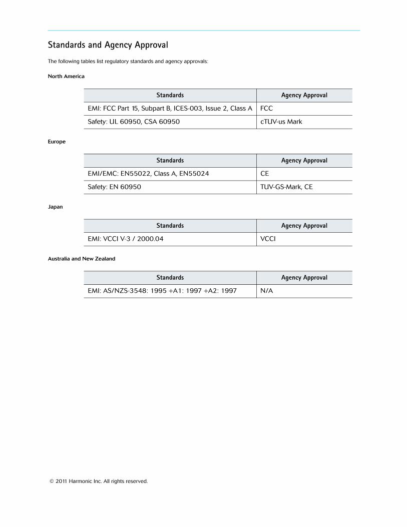
copy 2011 Harmonic Inc All rights reserved
Documentation ConventionsThis manual uses some special symbols and fonts to call your attention to important information The following symbols appear throughout this manual
DANGER The Danger symbol calls your attention to information that if ignored can cause physical harm to you
CAUTION The Caution symbol calls your attention to information that if ignored can adversely affect the performance of your Harmonic product or that can make a procedure needlessly difficult
LASER DANGER The Laser symbol and the Danger alert call your attention to information about the lasers in this product that if ignored can cause physical harm to you
NOTE The Note symbol calls your attention to additional information that you will benefit from heeding It may be used to call attention to an especially important piece of information you need or it may provide additional information that applies in only some carefully delineated circumstances
TIP The Tip symbol calls your attention to parenthetical information that is not necessary for performing a given procedure but which if followed might make the procedure or its subsequent steps easier smoother or more efficient
In addition to these symbols this manual uses the following text conventions
Data Entry indicates text you enter at the keyboard
User Interface indicates a button to click a menu item to select or a key or key sequence to press
Screen Output shows console output or other text that is displayed to you on a computer screen
Bold indicates the definition of a new term
Italics used for emphasis cross-references and hyperlinked cross-references in online documents
Table of Contents
copy 2011 Harmonic Inc 6 Ion AVC HD Version 10 Rev H
Table of Contents
Chapter 1 Preface11 Manual Organization 9
Chapter 2 Introduction21 Operating Environment 1022 General Features 1023 Video Features 1224 Audio Encoding Features 13
241 Onboard Audio 13242 AIC Adapter 13
25 AVC Encoding 1426 Digital Program Insertion Support 1427 HHP Support 1428 Closed-Captions Support 14
281 Japanese Standard Close Captions Support 15282 ARIB B-37 Captions 15
29 Front Panel 15291 Front Bezel 15292 Local Control Panel 15293 LEDs 15294 Modes of Operation 16
210 Back Panel 162101 AC Power and Fuse 172102 Audio Input Ports 172103 Video Input Ports 172104 IP Output Port 182105 Ethernet Management Port 182106 Fault Relay Port 182107 Serial Data Port 18
211 Back Panel LEDs 182111 Main Board LEDs 192112 Audio Port LEDs 192113 Video Lock LEDs 19
Chapter 3 Installation31 Preparation 2032 Unpacking 2033 Installing the Encoder in a Rack 20
331 Rack Guidelines 21332 Chassis Warnings for Rack Mounting and Servicing 21333 Airflow 21334 Attaching the Rack Rails 22335 Mounting the Encoder 23
Table of Contents
copy 2011 Harmonic Inc 7 Ion AVC HD Version 10 Rev H
34 Installing Encoder Software 2335 Cabling the Encoder 24
351 Back Panel 24352 Connecting the Audio Input Cables 24353 Connecting the Video Input Cables 25354 Connecting the IP Output Cables 25355 Connecting the Ethernet Management Cable 25356 Connecting the AC Power 25
Chapter 4 Operating the Encoder41 Operating with NMX Digital Service Manager 2742 Using the Front Panel 27
421 The Keypad 27422 Front Panel Display 28423 Setting the Encoder Network Properties 28424 Viewing the Encoder MAC Address 29425 Viewing the Encoder Serial Number 29
43 Licensing Information 30
Chapter 5 Maintenance and Troubleshooting51 Air Filters 31
511 Maintaining the Air Filters 31512 Removing and Replacing the Air Filters 32
52 Fuse 32521 Replacing the Fuse 33
53 Contacting Harmonic Support 33
Appendix A Encoder SpecificationsA1 Environment Specifications 34A2 Port Specifications 35A3 Port Pinouts 35
A31 Ethernet Management Port 35A32 Fault RelayGPI Ports 36
Appendix B Audio and Video SpecificationsB1 AIC Features 38B2 Dolby Digital (AC-3) Audio 40B3 Video Specifications 41B4 VITC Support 41
Appendix C Encoder Back Panel Slot LocationsC1 Adapter Configurations for All Encoders 42
C11 Additional Adapter Configurations for FLEX-based Encoders 42C12 Viewing the Control Board (CPC) Revision Information 43
Appendix D Boot SequenceD1 Local Control Panel Display Messages during Bootup 44D2 Other Local Control Panel Display Messages 44
Table of Contents
copy 2011 Harmonic Inc 8 Ion AVC HD Version 10 Rev H
D21 Resetting the Encoder 44D22 Loading New Software 45
Appendix E Wiring the ndash48 VDC Power SupplyE1 Getting Started 46E2 Power Source Specifications 46E3 Overcurrent Protection 46E4 Wiring Requirements 46E5 Power Connector 47E6 Assembling the DC Input Power Cable 47
Appendix F DiviComtrade FLEX Decoding ModuleF1 Introduction 49F2 Video Decoding Specifications 49F3 Audio Passthrough Specifications 50F4 Audio Decode Specifications 51
F41 Decoding Resource Considerations 51F5 Ancillary Data Specifications 53F6 Input Specifications 53F7 Output Specifications 54F8 Environmental and Physical 54F9 Module Slots 55F10 Installing the FLEX Decoding Module 55
F101 Installing a Module 55F11 Cabling the FLEX Module 56F12 Re-Encode Chassis Scenarios 56
F121 2 - Channel 56F122 4 - Channel 58
F13 Configuring the FLEX Module in NMX 58
Appendix G Divicomtrade RF Input CardG1 RF Specifications 59G2 Output Specifications 60G3 Environmental and Physical 60
Appendix H AB Power SwitchH1 Introduction 61H2 Card Status 62
Index 63
copy 2011 Harmonic Inc 9 Ion AVC HD Version 10 Rev H
Chapter 1Preface
This manual describes the Harmonic DiviComtrade Ion AVC HD MPEG-4 AVC High Definition Multiservice Encoder
11 Manual OrganizationThis manual contains the following chapters
Chapter 2 Introduction introduces the encoder and describes its features
Chapter 3 Installation provides a hardware overview including a description of the back panel ports connector specifications and rack-mounting instructions
Chapter 4 Operating the Encoder describes how to begin configuring the encoder using NMX or the front panel
Chapter 5 Maintenance and Troubleshooting describes maintenance and what to do in the event of problems
Appendix A Encoder Specifications describes specifications and physical characteristics of the back panel ports and port pinouts environment specifications and input and output specifications
Appendix B Audio and Video Specifications provides specifications for AIC AHC and video encoding
Appendix C Encoder Back Panel Slot Locations shows the numbering of the back panel slots NMX uses the slot number to differentiate between cards of the same type within the encoder
Appendix D Boot Sequence describes the encoder boot sequence including the messages that appear on the front panel
Appendix E Wiring the ndash48 VDC Power Supply provides specifications for the optional DC power supply and wiring instructions
Appendix F DiviComtrade FLEX Decoding Module provides details about the DiviCom FLEX decoding module
Appendix G Divicomtrade RF Input Card provides specifications for the DiviCom RF Input Card
Appendix H AB Power Switch provides specifications for the AB Power Input Switch card
copy 2011 Harmonic Inc 10 Ion AVC HD Version 10 Rev H
Chapter 2Introduction
The DiviComtrade Ion AVC HD MPEG-4 AVC High Definition Multiservice Encoder series uses the MPEG-4 Part 10 (AVC) also known as ITU-T H264 standard to compress its video streams It accepts up to four high definition (HD) serial digital video inputs and up to ten stereo pairs of digital audio inputs The encoder output is MPEG-2 Transport Stream (TS) transmitted over IP transport
This chapter describes
The environment in which you can operate the Ion AVC HD
General features
Video encoding features
Audio encoding features
Support for AVC DiviTrackIPtrade DPI and HHP
The front and back panels
21 Operating EnvironmentThe encoder operates under the control of NMXtrade Digital Service Manager NMX manages multiple Ion AVC HD encoders and other devices NMX provides full configuration of the Ion AVC HD platform ports services and PSI as well as alarm management You configure a few initial network settings from the front panel of the encoder The encoder operates within an IP environment therefore encoders and multiplexers do not need to be in the same physical location Harmonic recommends discussing your planned network architecture with a Harmonic representative before implementation
22 General Features Table 2-1 describes general features supported by the Ion AVC HD See the following tables for more information about video and audio compression
NOTE Internal Ion encoder audio adapters only support one audio codec at a time The three pairs of audio channels must use AC-3 MPEG2 or AAC audio not a mixture of both If more than one codec is required you must use another audio adapter Passthrough can be conducted on any codec For example you can do MPEG L2 compression on the first pair and AC-3 passthrough on the second pair
Table 2-1 General Features
Feature Description
Hardware
Chassis Compact 1-RU Mounts in Electronic Industries Association (EIA) standard rack
Local control panel Two-line 20-character vacuum fluorescent display (VFD) 24-button keypad (includes Help key) Four status LEDs
Chapter 2 Introduction General Features
copy 2011 Harmonic Inc 11 Ion AVC HD Version 10 Rev H
Software
Control NMX Digital Service Manager Front control panel (for setting management IP address)
Upgrades From NMX (see the NMX online help for details)
Video input Up to four high definition video encoders per chassis
Audio input AIC Digital or analog stereo inputs Two stereo pairs per AIC Complete embedded audio extraction of eight pairs from four
groups from serial digital video input (48 kHz synchronous to video only)
MPEG-1 Layer II stereo compression
Dolby Digitala (AC-3) stereo compression
Dolby Digitala (20 or 51) passthrough
AACHE AACb 20 audio compression
On-board audio Embedded digital multichannel or multiple stereo input only
One 51 surround or three stereo pairsc
Complete embedded audio extraction of twelve pairs from six groups from serial digital video input (48 kHz synchronous to video only)
MPEG-1 Layer II stereo compression
Dolby Digitala 20 stereo compression Dolby Digital (20 or 51) passthrough and encoding
AACHE AACd 51 or 20 audio compression with either MPEG-2 or MPEG-4 encapsulation
IP output One 101001000 Base-T port with second redundant channelconnector
Dual-mode IP output or manual channel switch for redundancy Hotwarm standalone IP channel redundancy Same-source IP output support Automatic port redundancy UDP and RTP encapsulation support Unicast and multicast address support Ping and ARP support Single-program transport stream (SPTS) output Null packets can be preserved to match the exact rate of SPTS
(video server integration) Forward-error correction (FEC) may be applied via the SMPTE
2022 Annex C method Use of FEC requires RTP encapsulation
Connector type RJ-45 Harmonic Heartbeat Protocol (HHP) redundancy protection
PSI support Generated by NMX when managed by NMX
Table 2-1 General Features continued
Feature Description
Chapter 2 Introduction Video Features
copy 2011 Harmonic Inc 12 Ion AVC HD Version 10 Rev H
23 Video Features Table 2-2 describes video encoding features supported by the encoder
Table 2-2 Video Features
Feature Support
Input format
Video format
Encoding mode
Horizontal Resolutions
Frame rates
Picture-in-picture
Advanced encoding
Video Processing
Closed captioning Support for
Caption encapsulation
Alarms Current and history alarm logs in NMX Alarm Manager SNMP alarm forwarding
IRIStrade Support Data reporting (losscorrupted and silent audio) of input audio
a Dolby is a registered trademark of Dolby Laboratories AC-3 and Dolby E are trade-marks of Dolby Laboratories
b The AIC uses an implementation of AACHE AAC also known as aacPlustrade developed by Coding Technologies (httpwwwcodingtechnologiescom) Trademarks of Coding Technologies GmbH are the property of Dolby Laboratories All rights reserved
High definition serial digital interface (HD-SDI)
1080i720p 169 aspect ratio
AVC (MPEG-4 Part 10) Main or High Profile Level 4
1080i x 1920 1080i x 1440 1080i x 1280 1080i x 960 720p x 1280 720p x 960 720p x 640
1080i at 2997 and 25 fps 720p at 5994 fps
MSTV
Flexible GOP structure
PSIP tables spooling
SMPTE 333M (serial EIA-708-B)
ATSCSCTE North American DBS SMTPE 334-1(VANC) 525-line VBI support for 608 to 708 conversion
Table 2-1 General Features continued
Feature Description
Chapter 2 Introduction Audio Encoding Features
copy 2011 Harmonic Inc 13 Ion AVC HD Version 10 Rev H
24 Audio Encoding Features This section describes both the onboard audio and AIC adapter features
241 Onboard AudioTable 2-3 describes audio encoding features supported by the encoder equipped only with onboard audio
Table 2-3 Audio Encoding Features Onboard Audio
Feature Support
Digital input
Input format
Audio encoding format
242 AIC AdapterTable 2-4 describes audio encoding features supported by the encoder equipped with an AIC adapter
Table 2-4 Audio Encoding Features AIC
Feature Support
Stereo pairs
Input format
Analog reference level specification
Reference levels in the range -10 dBu to +4 dBu may be specified in 05 dBu steps Alignment tone at reference level is placed at -20 dBFS per SMPTE RP155
Audio encoding format
THD+noise 00032 measured at ndash3bBFS
Digital multichannel or multiple stereo inputs One 51 surround or three stereo pairs Complete embedded audio extraction of twelve pairs from six
groups from serial digital video inputs (48 kHz synchronous to video only)
Digital AES3 SPDIF IEC60958 Embedded in HD-SDI (synchronous to video)
AACHE AAC 20 stereo compression Single channel dual stereo and joint stereo (AACHE AAC
only)
Up to 10 stereo pairs Two stereo pairs per AIC
Digital AES3 or SPDIF Analog balanced or unbalanced Embedded from SDI (video)
MPEG-1Layer II 20 (stereo) compression Dolby Digital (AC-3) 20 stereo compression Dolby Sigital 20 or 51 passthrough AACHE AAC 20 stereo compression Single channel dual stereo and joint stereo (MPEG-1 Layer II
and AACHE AAC only) Single PID per Channel support with MPEG-1 Layer II
Chapter 2 Introduction AVC Encoding
copy 2011 Harmonic Inc 14 Ion AVC HD Version 10 Rev H
25 AVC EncodingThe Ion AVC HD video compression complies with the AVC (MPEG-4 Part 10) Main Profile
26 Digital Program Insertion Support The Ion AVC HD encoder supports digital program insertion (DPI) Ion AVC HD accepts external automation system DPI commands (triggers) via Ethernet These commands are sent via the SCTE 104 protocol and result in the encoder placing SCTE 35 DPI messages in the outgoing MPEG Transport Stream (TS) (The Ion AVC HD also accepts commands via the SCTE DVS525 draft protocol)
The resulting messages carry metadata used by downstream content insertion equipment to choose and insert the proper content When using an external automation system that system provides the metadata values via the SCTE 104 commands The metadata is included in the resulting SCTE 35 messages which are placed in the outgoing MPEG Transport Stream
27 HHP Support Harmonic Heartbeat Protocol (HHP) is a proprietary Harmonic protocol used to prevent duplicate IP output after a redundancy switch and to initiate a redundancy switch in some 1x1 hot backup scenarios HHP packets are sent over a unique multicast address on the video IP network
In some redundancy switches NMX may not be able to shut down the IP output from the primary device For example if the connection between the device and NMX is lost NMX issues a time-out alarm for the device and provisions the backup device with the circuits from the primary device However the primary device may still be operating normally even though it lost communication with NMX In this case you now have two devices sending the same output
To prevent this scenario enable HHP When you enable HHP a backup device taking over in a redundancy switching event will send a command (over a unique multicast address on the video IP network) to turn off the outputs of the formerly active device During a redundancy switch the backup device assumes all responsibilities of the primary device including sending HHP messages at the same multicast address
If a primary device detects HHP messages sent to its multicast IP address it immediately backs off and stops sending output This leaves the backup device free to operate without the primary device sending the same output
In 1x1 hot backup configurations the HHP protocol can also initiate a redundancy switch In this case the backup device monitors the primary device by listening for HHP messages If the backup device does not detect an HHP message from the primary device during a specified interval it initiates a redundancy switch and assumes operation as the primary device
28 Closed-Captions SupportThe CEA-708 closed captions include space for CEA-608 data The encoder can receive them either via serial port (compliant with SMPTE 333M one service per chassis) or in VANC (compliant with SMPTE 334-1 one service per encoder card mounted) Extraction of CEA-608 data from Line 21 of SD video is also supported
Chapter 2 Introduction Front Panel
copy 2011 Harmonic Inc 15 Ion AVC HD Version 10 Rev H
The placement of CEA-708 captions into the MPEG-2 video ES is compliant with ATSC A53 Part 4 Placement of CEA-608 data is available compliant with a variety of industry standard and proprietary methods Consult the NMX or SAG online help for more details
281 Japanese Standard Close Captions SupportThe Ion AVC HD provides support for Japanese standard captions compliant with ARIB B24 The Ion AVC HD encoder supports extraction (from VANC) compliant with ARIB B 37
282 ARIB B-37 CaptionsThis refers to the Japanese standard and the input is in VANC while the captions are placed in a separate PID
29 Front Panel Figure 2-1 shows the front panel of the DiviCom Ion AVC HD encoder
Figure 2-1 Front panel
291 Front Bezel The encoder has a detachable front bezel that snaps on top of the local control panel and provides access to the reusable air filters See 51 Air Filters on page 31 for information about cleaning the air filters
292 Local Control Panel The local control panel allows configuration of the initial network settings for the encoder From the front panel you can set the encoder IP address subnet mask and default gateway and view the encoder MAC address
293 LEDs The four LEDs on the front panel indicate the operational state of the encoder Table 2-5 describes the front panel LEDs
Table 2-5 Front Panel LEDs
LED Color Description
Power Yellow The Power LED is yellow while the encoder initializes after startup
Green The Power LED turns green when the encoder initialization is complete and the management interface is enabled and ready
Fault Red The Fault LED lights when the application software detects an alarm
Chapter 2 Introduction Back Panel
copy 2011 Harmonic Inc 16 Ion AVC HD Version 10 Rev H
294 Modes of OperationThere are three modes of operation on the encoder and are set globally through the NMX interface for all encoder platforms and locally on SAG as well
Default Mode
Verbose Front Panel Mode
NMX Control Over Second Line
2941 Default Mode
The default mode (with no provision from the NMX application) is the default mode For more information on the default mode refer to the NMX online help
2942 Verbose Front Panel
The front panel displays the device name on line one and either the card number or Broadcast Operations Control (BOC) as well as the (sliding) service name on the second line For more information on the verbose front panel refer to the NMX online help
2943 NMX Control Over Second Line
Under this option you can the front panel classic display mode as well as channel name and bitrate For more information on the NMX control on the second line refer to the NMX online help
210 Back Panel The back panel contains the following elements as shown in Figure 2-2
NOTE See Table C-1 on page 42 for information on which adaptersmodules are supported in your back plane
Local Yellow The Local LED lights when the encoder is operating in local mode
Activity Yellow The Activity LED lights when the encoder generates an MPEG-2 transport stream It blinks slowly when MPEG packets are being transmitted steadily It blinks fast or intermittently when the transmission rate is slow or intermittent
AC power plug and fuse Up to four video input ports Up to two stereo digital audio input
ports per AIC adapter Video lock LEDs Fault relay port Fault and Locator LEDs ASIIPFLEX modules (optional)
Serial data input port One 10100 Base-T Ethernet
management port One 101001000 Base-T Fast Ethernet
output port with second redundant channel and connector
Table 2-5 Front Panel LEDs continued
LED Color Description
AC Power
Fuse Cover
ASI module
Fault andLocator LEDs
FaultRelayPort
EthernetManagement Port
EthernetOutput Ports
Plug Video Input Ports(optional)FLEX module(optional)
Chapter 2 Introduction Back Panel
copy 2011 Harmonic Inc 17 Ion AVC HD Version 10 Rev H
Figure 2-2 Back panel
2101 AC Power and Fuse The AC power plug accommodates standard IEC 120 VAC and 250 VAC power cords The chassis does not have a power switch The unit powers on automatically when you plug it in
See 356 Connecting the AC Power on page 25 for cabling instructions
The fuse panel is located beside the power plug The encoder requires one slow blow 40 A 250 V fuse 5 x 20 mm See 52 Fuse on page 32 for replacement instructions
2102 Audio Input PortsThe Electra 7000 can be configured with a combination of onboard audio AIC and AHC adapters
21021 AIC Adapter
Each AIC has two digital audio input ports (BNC connectors) The encoder supports up to five AICs Two BNC ports support AES3 or SPDIF to provide the stereo digital audio input to the AIC module
Figure 2-3 illustrates the audio input ports on an AIC adapter
Figure 2-3 Audio Input ports
2103 Video Input Ports The back panel contains up to four video input ports These are BNC coaxial ports that support high definition serial digital video input
Each video input port connects internally to a video processing card The video processing cards are not visible from the encoder back panel
See 353 Connecting the Video Input Cables on page 25 for cabling instructions
Digital Audio Input Port 1
Digital Audio Input Port 2
Chapter 2 Introduction Back Panel LEDs
copy 2011 Harmonic Inc 18 Ion AVC HD Version 10 Rev H
2104 IP Output Port One 101001000 Base-T Ethernet port provides two redundant IP output channels The two RJ-45 connectors are labeled GbE PRI and BKUP
The IP output port supports manual redundancy The port also supports hotwarm standalone redundancy when the primary IP data channel detects a cable disconnection the primary channel stops outputting and the backup channel takes over
In manual redundancy you can enable one channel or both channels If you enable one channel you must manually switch to the other channel after a service-affecting alarm If you enable both channels the encoder outputs the same data from both channels
See 354 Connecting the IP Output Cables on page 25 for cabling instructions Set the IP address and other network information for the IP output ports using NMX
2105 Ethernet Management Port The Ethernet management port labeled ETH is 10100 Base-T and uses an RJ-45UTP cable to connect to an Ethernet network See 355 Connecting the Ethernet Management Cable on page 25 for cabling instructions See A31 Ethernet Management Port on page 35 for pinout information
2106 Fault Relay Port The fault relay port connects to a Form C relay that can switch up to 025 amps at 30 VDC See A32 Fault RelayGPI Ports on page 36 for port pinout and additional information
The encoder energizes the fault relay during normal operation The fault condition is indicated in the same way as the encoderrsquos powered-off condition which is with the relay de-energized You can use this method to correctly identify a power supply failure or loss of input power The signals are normally open or normally closed
NOTE Any alarm causes the fault relay to change to the fault state When multiple alarms accumulate all alarms must be active for the relay state to change
2107 Serial Data Port The serial port can be used for serial 708 input per 333M
211 Back Panel LEDs The following sections describe the back panel LEDs and their functions
Chapter 2 Introduction Back Panel LEDs
copy 2011 Harmonic Inc 19 Ion AVC HD Version 10 Rev H
2111 Main Board LEDsThe back panel contains two LEDs on the main board Table 2-6 describes the LEDs located on the main board
Table 2-6 Rear Panel Main Board LEDs
LED Color Description
Locator Blue The Locator LED lights when this encoder is enabled through NMX Use the Locator LED to help you identify a specific chassis in a rack
Fault Red The Fault LED lights when the application software detects an alarm The front panel and back panel Fault LEDs light at the same time
2112 Audio Port LEDs Each AIC adapter contains a status LED Table 2-7 describes the LED located on each AIC adapter
Table 2-7 Rear Panel Audio Port LEDs
LED Color Description
STAT Blue The Audio Port LED is on during bootup as the audio input card comes online The LED is off during normal operation
2113 Video Lock LEDs Each video port has an associated Video Lock LED Table 2-8 describes the LED located on each video port
Table 2-8 Rear Panel Video Lock LEDs
LED Color Description
Video 1Video 2
Green When illuminated and steady the Video Lock LED indicates that the video signal is locked When off the Video Lock LED indicates that the encoder has lost video sync
copy 2011 Harmonic Inc 20 Ion AVC HD Version 10 Rev H
Chapter 3Installation
This chapter provides detailed instructions for installing a DiviCom Ion AVC HD encoder in a standard 19-inch rack and connecting cables
The chapter describes
How to prepare and unpack the Ion AVC HD
How to install the encoder in a rack
How to update the encoder software
How to connect the cables
31 PreparationYou need a Phillips screwdriver to mount the encoder in a standard 19-inch rack Harmonic ships the necessary rack-mount screws and rack rails
32 Unpacking The encoder comes in a specially designed shipping container that ensures the integrity of your encoder hardware during shipping and handling To avoid damage to the component follow the unpacking instructions that come with the encoder
When you unpack the encoder you should find the following items
Encoder
Standard IEC power cord
Spare air filters
Software warranty agreement
Harmonic ships rack-mounting kits in a separate shipping container
33 Installing the Encoder in a Rack You can install the encoder in different sizes and types of racks For rack assembly instructions consult the manual that came with the rack or the customer service department of the rack manufacturer
This section describes how to mount the encoder in a standard 19-inch rack using the two side-mount rails included in the rack-mounting kit A 30-inch-deep rack with a spacer or chimney between racks with multiple encoders is the recommended rack setup However these rails work for racks that are 30 to 36 inches deep
When you view the rack from the rear the power rail should be installed on the left side
Chapter 3 Installation Installing the Encoder in a Rack
copy 2011 Harmonic Inc 21 Ion AVC HD Version 10 Rev H
331 Rack GuidelinesWhen operating the encoder in the rack ensure that
The ambient temperature around the unit (which may be higher than room temperature) is within the limit specified for the unit
There is sufficient airflow around the unit
Electrical circuits are not overloaded consider the nameplate rating of all the connected equipment
There is overcurrent protection
The equipment is properly grounded
No objects are placed on top of the unit
332 Chassis Warnings for Rack Mounting and Servicing
CAUTION To prevent bodily injury when mounting or servicing this unit in a rack you must take special precautions to ensure that the system remains stable The following guidelines are provided to ensure your safety
This unit should be mounted at the bottom of the rack if it is the only unit in the rack
If the rack will hold a number of units load the rack from the bottom to the top with the heaviest component at the bottom of the rack
If the rack is provided with stabilizing devices install the stabilizers before mounting or servicing the unit in the rack
ATTENTION Pour eacuteviter toute blessure corporelle pendant les opeacuterations de montage ou de reacuteparation de cette uniteacute en casier il convient de prendre des preacutecautions speacuteciales afin de maintenir la stabiliteacute du systegraveme Les directives ci-dessous sont destineacutees agrave assurer la protection du personnel
Si cette uniteacute constitue la seule uniteacute monteacutee en casier elle doit ecirctre placeacutee dans le bas
Si cette uniteacute est monteacutee dans un casier partiellement rempli charger le casier de bas en haut en placcedilant lrsquoeacuteleacutement le plus lourd dans le bas
Si le casier est eacutequipeacute de dispositifs stabilisateurs installer les stabilisateurs avant de monter ou de reacuteparer luniteacute en casier
WARNUNG Zur Vermeidung von Koumlrperverletzung beim Anbringen oder Warten dieser Einheit in einem Gestell muumlssen sie besondere Vorkehrungen treffen um sicherzustellen daszlig das System stabil bleibt Die folgenden Richtlinien sollen zur Gewaumlhrleistung Ihrer Sicherheit dienen
Wenn diese Einheit die einzige im Gestell ist sollte sie unten im Gestell angebracht werden
Bei Anbringung dieser Einheit in einem zum Teil gefuumlllten Gestell ist das Gestell von unten nach oben zu laden wobei das schwerste Bauteil unten im Gestell anzubringen ist
Wird das Gestell mit Stabilisierungszubehoumlr geliefert sind zuerst die Stabilisatoren zu installieren bevor sie die Einheit im Gestell anbringen oder sie warten
333 Airflow The airflow through the encoder is critical for maintaining the proper temperature range Fans in the chassis draw air in through the front bezel and through the encoder The airflow ventilates out the right side (front view)
Chapter 3 Installation Installing the Encoder in a Rack
copy 2011 Harmonic Inc 22 Ion AVC HD Version 10 Rev H
CAUTION Do not obstruct the airflow of the encoder Severe equipment damage can result when the encoder cannot properly exhaust the airflow
334 Attaching the Rack Rails Attach the side-mount rack rails to the rack to hold the encoder in place Figure 3-1 illustrates the parts of the rack rails
Figure 3-1 Rack rails
To attach the rack rails to the rack
1 If needed place a Tinnermantrade speed nut with the nut on the outside of the rack over the holes to which you would like to mount the rails
NOTE Each of the four rack posts requires two speed nuts
2 Position the rack rails so the shelves are toward the inside of the rack
3 Using the 10 screws provided with the encoder screw the mounts into the speed nuts from the inside of the rack using the rack-mount holes that line up with the holes on the rack posts
Figure 3-2 illustrates attaching the rails
Figure 3-2 Attaching the rails to the rack
Chapter 3 Installation Installing Encoder Software
copy 2011 Harmonic Inc 23 Ion AVC HD Version 10 Rev H
CAUTION Make sure to install the rack rails with the shelf at the top of the rail If you install the rail upside down the rail blocks the encoder air vents which can result in overheating the encoder
335 Mounting the EncoderTo mount the encoder in a rack
1 Using both hands grasp the outside corners of the plastic front bezel and slowly pull to detach it from the encoder and expose the mount holes See Figure 3-3
2 Gently slide the encoder to rest on the rack rails
3 Push the encoder back until the rack-mount holes in the front of the encoder line up with the rack posts
4 Insert four screws through the mount holes in the front of the encoder through to the corresponding holes on the rack posts
5 Tighten the screws with a screwdriver
6 Carefully replace the front bezel of the encoder making sure you do not damage the air filters
Rack-mount Holes
Front Bezel
Figure 3-3 Mounting the encoder
34 Installing Encoder SoftwareYour encoder comes from the factory with the latest released software version installed Harmonic periodically releases software updates You can download new software to the encoder using NMX See the NMX online help for instructions for how to download and begin running new encoder software
Chapter 3 Installation Cabling the Encoder
copy 2011 Harmonic Inc 24 Ion AVC HD Version 10 Rev H
35 Cabling the Encoder CAUTION Do not make any cable connections when the power cord is connected You must unplug the power cable to turn off the encoder
The next sections describe how to connect the following cables
Video input
IP output
Ethernet management
Power
351 Back PanelFigure 3-4 shows a sample back panel of the DiviCom Ion AVC HD encoder configured with optional ASI and FLEX modules
AC Power
Fuse Cover
ASI module
Fault andLocator LEDs
FaultRelayPort
EthernetManagement Port
EthernetOutput Ports
PlugVideo Input Ports
(optional)FLEX module(optional)
Figure 3-4 Back panel
352 Connecting the Audio Input Cables An encoder may have up to five audio input cards (AICs) each of which has two stereo digital audio ports or up to five audio adapters (AHC AHC-RAC or AHC-561) each of which has four stereo digital audio ports When the encoder is equipped with an AHC-RAC used to support native AES input only three of the four digital audio ports on a card can be used at one time
To connect the audio cables
Connect a coaxial cable with a BNC connector from the digital audio port to the audio source On each AIC the digital audio ports are labeled DGTL AUD1 and DGTL AUD2 On each AHC the digital audio ports are labeled DGTL AUD1 DGTL AUD2 DGTL AUD3 and DGTL AUD4 For multichannel audio use three cables to connect the surround mix connecting LR to DGTL AUD1 CLfe to DGTL AUD2 and LsRs to DGTL AUD3 which maps the channels to AES3 pairs as defined by SMPTE 320M If the encoder is equipped with an AHC-RAC then one more stereo pair can be connected to DGTL AUD4 Otherwise the fourth connector is not used
Chapter 3 Installation Cabling the Encoder
copy 2011 Harmonic Inc 25 Ion AVC HD Version 10 Rev H
353 Connecting the Video Input Cables Your encoder has up to four video input ports The video input ports accept serial digital video To connect the video cables
1 Connect a coaxial cable with a BNC connector from the first video source to the Video 1 port on the encoder
2 Continue connecting the additional video sources to the remaining video ports
354 Connecting the IP Output Cables The encoder has one IP output port with two redundant channels and two RJ-45 connectors
NOTE The network hosting the IP output traffic must be a different network from your management network and must be configured with a different IP address
NOTE Harmonic recommends that shielded and grounded Ethernet cables be used on all Ethernet ports
To connect the IP output cables
1 Connect an Ethernet cable from the primary IP output port to a port on a network switch or router not a hub
2 Optionally connect the backup IP output port to a different switch or router to facilitate redundancy
3 Configure the Ethernet switch to support autonegotiation by setting each port to ldquoset speed autordquo and ldquoset duplex autordquo
NOTE Failure to properly configure the Ethernet switch could result in a mismatch between the IP output and the switch
Harmonic supports 101001000 Base-T and is fully compliant with IEEE 8023 8023u and 8023as standards
355 Connecting the Ethernet Management Cable The Ethernet management port allows communication between NMX and the encoder
To connect the Ethernet management cable
Connect an RJ-45UTP cable from the encoderrsquos back panel 10100 Base-T port to a port on an Ethernet switch
NOTE The network hosting the IP output traffic should be a different network from your management network
356 Connecting the AC Power The encoder AC power supply uses autosensing to adjust to different incoming voltages
CAUTION This product relies on the buildingrsquos electrical installation for short-circuit (overcurrent) protection Ensure that a fuse or circuit breaker no larger than 120 VAC 20 A US (240 VAC 20 A international) is used on the phase conductors (all current-carrying conductors)
Chapter 3 Installation Cabling the Encoder
copy 2011 Harmonic Inc 26 Ion AVC HD Version 10 Rev H
ATTENTION Pour ce qui est de la protection contre les courts-circuits (surtension) ce produit deacutepend de lrsquoinstallation eacutelectrique du local Veacuterifier qursquoun fusible ou qursquoun disjoncteur de 120 V alt 20 A US maximum (240 V alt 20 A international) est utiliseacute sur les conducteurs de phase (conducteurs de charge)
WARNUNG Dieses Produkt ist darauf angewiesen daszlig im Gebaumlude ein Kurzschluszlig-bzw Uumlberstromschutz installiert ist Stellen sie sicher daszlig eine Sicherung oder ein Unterbrecher von nicht mehr als 240 V Wechselstrom 20 A (bzw in den USA 120 V Wechselstrom 20 A) an den Phasenleitern (allen stromfuumlhrenden Leitern) verwendet wird
To connect the power cord
Connect the power cord to the power plug on the encoder back panel and connect the power cord to the power outlet
CAUTION The power supply cord is used as the main disconnect device Ensure that the socketoutlet is locatedinstalled near the equipment and is easily accessible
ATTENTION Le cordon drsquoalimentation est utiliseacute comme interrupteur geacuteneacuteral La prise de courant doit ecirctre situeacutee ou installeacutee agrave proximiteacute du mateacuteriel et ecirctre facile drsquoacceacutes
WARNUNG Das Netzkabel dient als Netzschalter Stellen sie sicher das die Steckdose einfach zugaumlnglich ist
Power Supply Cord Notice
CAUTION This unit has more than one power supply connectionrsquo all connections must be removed to remove all power from this unit
ATTENTION Cette uniteacute est eacutequipeacutee de plusieurs raccordements dalimentation Pour supprimer tout courant eacutelectrique de luniteacute tous les cordons dalimentation doivent ecirctre deacutebrancheacutes
WARNUNG Diese Einheit verfuumlgt uumlber mehr als einen Stromanschluszlig um Strom gaumlnzlich von der Einheit fernzuhalten muumlssen alle Stromzufuhren abgetrennt sein
Laser warning
Warning Class 1 laser product
Attention Produit laser de classe 1
Warnung Laserprodukt der Klasse 1
copy 2011 Harmonic Inc 27 Ion AVC HD Version 10 Rev H
Chapter 4Operating the Encoder
After installing the encoder in a rack and connecting the cables as described in Chapter 3 Installation configure the encoder platform and services
The chapter describes
How to use NMX Digital Service Manager to configure the Ion AVC HD
How to use the Ion AVC HD front panel
41 Operating with NMX Digital Service ManagerWhen you use NMX Digital Service Manager to manage the encoders in your network you perform all encoder configuration including IP address assignment in NMX You do not need to do any configuration from the encoder front panel
See the NMX online help for instructions for adding an encoder to an NMX network group You will need to know the encoder MAC address when you add the encoder to a network group See 424 Viewing the Encoder MAC Address on page 29 for instructions for viewing the MAC address in the front panel display
42 Using the Front Panel You can perform some initial network configuration from the encoder front panel From the front panel you can set the encoderrsquos IP address default gateway and subnet mask and you can view the encoderrsquos MAC address and serial number
421 The Keypad The keypad on the local control panel provides the following functions
Access to the menus
Navigation through the menu hierarchies to their parameters
Editing capabilities
Figure 4-1 shows the keypad
Hot Keys Navigation andFunction Keys
Alphanumeric Keys
Figure 4-1 Front panel keypad
Seven hot keys provide immediate access to the encoder menus The Network and Help hot keys are currently active The other hot keys are reserved for future use
Chapter 4 Operating the Encoder Using the Front Panel
copy 2011 Harmonic Inc 28 Ion AVC HD Version 10 Rev H
Navigation and function keys located to the right of the hot keys provide a tool for navigating through the menu hierarchies and changing parameter values Use the alphanumeric keys to enter new values
422 Front Panel Display
The two-line 20-character vacuum fluorescent display (VFD) shows the menus parameters and options As illustrated in Figure 4-2 line 1 of the local control panel display shows the menu path for the currently selected option To represent a path the VFD displays each submenu as two or more letters and a colon
Line 2 of the display shows the second line of a help message or a parameter value To change this value you must enter the new value using the keypad
NTWK Control IPParameter Requires
Value to be Edited
Value Setting
19216824101
Figure 4-2 Setting a value in the front panel display
A blinking cursor shows the current value A steady cursor shows the value being edited
Press the Help key to display an online message for the currently selected menu item
423 Setting the Encoder Network PropertiesBefore you can begin to configure the encoder you must set the encoder IP address subnet mask and default gateway The encoder ships with a default IP address based on the encoder serial number The default subnet mask is 255000 and the default gateway address is 10001
4231 Setting the IP Address
To set the encoder management port IP address
1 Press the NTWK hot key
The VFD display shows NTWK Configuration
2 Press the
v key to navigate to NTWK Control IP
3 Press Enter
4 Enter the IP address using the alphanumeric keys
TIP To enter a period press the Shift key and the 0 key
5 When you finish press Enter
Do not exit the Network menu because you can set the other properties from here
Chapter 4 Operating the Encoder Using the Front Panel
copy 2011 Harmonic Inc 29 Ion AVC HD Version 10 Rev H
4232 Setting the Subnet Mask
To set the subnet mask
1 Press the
v key to navigate to NTWK Control Subnet
2 Press Enter
3 Enter the subnet mask using the alphanumeric keys
TIP To enter a period press the Shift key and press the 0 key
4 When you finish press Enter
4233 Setting the Default Gateway Address
To set the gateway address
1 Press the
v
key to navigate to NTWK Gateway
2 Press Enter
3 Enter the default gateway using the alphanumeric keys
TIP To enter a period press the Shift key and press the 0 key
4 When you finish press Enter
5 Press Esc to exit the Network menu
424 Viewing the Encoder MAC Address You can view the encoder MAC address from the front panel
To view the encoder MAC address
1 Press the NTWK hot key
2 Press the
v
key several times to navigate to NTWK Control MAC
The MAC address appears beneath the parameter name
3 Press Esc to exit the parameter
425 Viewing the Encoder Serial NumberYou can view the encoder serial number from the front panel
To view the encoder serial number
1 Press the STAT hot key
2 Press the
v
key to navigate to STAT Serial Number
The serial number appears beneath the parameter name
3 Press Esc to exit the parameter
Chapter 4 Operating the Encoder Licensing Information
copy 2011 Harmonic Inc 30 Ion AVC HD Version 10 Rev H
43 Licensing InformationLicensing is required for some encoding features and you cannot enable those features without the appropriate licensing You can add licenses to your system at any time using the SAG (Web GUI) You must acquire licenses from Harmonic When licenses expire streams will continue to flow as configured but cannot be modified or re-enabled if disabled for any reason Streams that include features under license will raise alarms when their licensing expires Alarms will also be raised to advise you that licensing is required for a given feature if that feature is blocked Also any attempted changes after a license expires may be service affecting and other operations such as redundancy may not operate properly For additional information on using the Configuration Manager for licensing operations refer to your encoderrsquos online help
Under the Licensing tab (on Platform Configuration page) you can
Apply license keys that have been created and sent to you by Harmonic in a lic license file The license file is unique to a specific encoder and can be used on that encoder only once When you apply a license the system scans the encoder platform for the matching devicefeature and binds the license key to that encoder One lic file may contain multiple license keys Every key in the lic file will be applied One license key may unlock multiple instances of a feature There is no undo for applying licenses but you can delete them
Delete a license key and save the deletion receipt for return to Harmonic If you want to remove a license key from one device to use it on another you must delete it When you delete a key the device releases it and a unique deletion receipt is created This receipt must be sent to Harmonic so that the deleted license can be made available in the license database for use in a different encoder There is no undo for deletion You must provide the deletion receipt to Harmonic to make the license available for use again
View the current licenses that are on the encoder platform
To apply licenses
If you ordered a new license you received a file To install it on this encoder follow these steps
1 Click the Add license button The license Loader window opens
2 Type in the path and file name where you saved the new license file or use the Browse button and navigate to it
3 Click the Transfer button The encoder applies all the license keys that are in the lic file and binds them to the encoder The new licenses appear in the license table
4 Disable then re-enable the affected streams if applicable
To delete licenses
Contact Harmonic customer support for more information
copy 2011 Harmonic Inc 31 Ion AVC HD Version 10 Rev H
Chapter 5Maintenance and Troubleshooting
This chapter describes
How to maintain and replace the air filters and fuse
How to contact Harmonic Support
51 Air Filters The encoder uses two air filters to minimize dust and dirt in the circuitry and components in the chassis These filters are made of flexible compressed fiber spun from urethane foam Installed in the front of the encoder the filters are fire retardant and conform to UL 900 Class II specifications
The bezel filter is located inside the front bezel on the left side Figure 5-1 shows the dimensions of the bezel filter The notches on the left side and the cutouts in the middle can fit on either side of the front bezel mounting posts
532 inches
164 025 inchesinches
Figure 5-1 Bezel filter (front view)
The keypad filter is located behind the front panel keypad Figure 5-2 shows the keypad filter
645 inches
025 inches
164inches
Figure 5-2 Keypad filter (front view)
511 Maintaining the Air Filters The operating environment of the encoder plays a large factor in determining the life of the air filters Encoders that operate in dusty and dirty surroundings require more frequent inspections and filter cleaning than those operating in cleaner environments
Inspect and clean the filters with a frequency that is appropriate to the environment in which the encoder operates Harmonic recommends inspecting and cleaning the filters every six weeks to ensure proper airflow through the chassis
To clean dust and dirt from the filters you can use a vacuum cleaner to remove the dirt or you can rinse the filters in water You can also use soaps or mild detergents on the filters If you rinse the filters in water make sure that you squeeze the excess water from them before reinstalling them in the encoder You might need to order replacement filters if the filters become too dirty over time
Chapter 5 Maintenance and Troubleshooting Fuse
copy 2011 Harmonic Inc 32 Ion AVC HD Version 10 Rev H
512 Removing and Replacing the Air Filters You do not need to turn off the encoder when removing and replacing the air filters
5121 Removing and Replacing the Bezel Filter
To remove the front left filter from behind the front bezel
1 Grasp each side of the encoderrsquos front bezel with your hands
2 Carefully remove the front bezel by pulling it away from the encoder
3 Remove the filter from inside the front bezel
4 Inspect the air filter for dirt and clean it if necessary
NOTE When the filter is new its color is medium charcoal As dust and dirt collect in the porous filter material the filterrsquos color gradually changes to brown then an ash color
5 Replace the filter inside the front bezel Place the filter so that the long horizontal slot is at the bottom edge Carefully place the cutouts in the filter around the bezel mounting posts
6 Carefully replace the front bezel on the encoder making sure the filter does not fall out of the bezel
5122 Removing and Replacing the Keypad Filter
To remove the air filter from behind the keypad
1 Grasp each side of the encoder front bezel with your hands
2 Carefully remove the front bezel by pulling it away from the encoder
Note the location of the filter The keypad is screwed onto the front of the encoder through four mounting posts Cutouts on the filter wrap around the four posts and the right side of the filter extends past the keyboard
3 Remove the filter by pulling the left side of the filter up and away from the keyboard mounting posts then pulling up the right side
4 Inspect the air filter for dirt and clean it if necessary
5 Replace the filter by inserting the right side of the filter behind the keypad with the vertical slots around the mounting posts
6 Insert the left side of the filter placing the horizontal cutouts around the mounting posts
7 Carefully replace the front bezel on the encoder making sure the filter does not fall out of the bezel
52 Fuse Encoders use a slow blow 40 A 250 V fuse 5 x 20 mm The fuse is located on the back panel beside the power input A spare fuse is located in the fuse cover shown in Figure 5-3
Fuse cover
Figure 5-3 Fuse cover and AC power input
Chapter 5 Maintenance and Troubleshooting Contacting Harmonic Support
copy 2011 Harmonic Inc 33 Ion AVC HD Version 10 Rev H
521 Replacing the FuseTo replace the fuse
1 Unplug the power cord from the chassis
DANGER You must disconnect the power cord before removing the fuse
2 Pull down the fuse cover on the back panel
3 Remove the old fuse
4 Install the new fuse
DANGER Always replace the fuse with a fuse of the same rating and type Using a different fuse voids the Harmonic warranty and could result in fire or other electrical damage
5 Replace the fuse cover
6 Plug in the encoder
53 Contacting Harmonic SupportThe Harmonic Customer and Technical Support groups are available to help you with any questions or problems you may have regarding Harmonic products
For assistance from within the US and Canada call toll free
1888MPEGTWO (6734896)
For assistance from outside the US and Canada call
14084906477
The fax number is 4084906770
The email address is techhelpharmonicinccom
The corporate address for Harmonic Inc is
Harmonic Inc 549 Baltic Way Sunnyvale CA 94089 USA Attn Customer Support
The corporate telephone numbers for Harmonic Inc are
Tel 18007881330 (from the US and Canada) Tel +14085422500 (outside the US and Canada) Fax+14084906708
The web address for Harmonic Inc is wwwharmonicinccom
copy 2011 Harmonic Inc 34 Ion AVC HD Version 10 Rev H
Appendix AEncoder Specifications
This appendix contains a comprehensive list of the environment and physical characteristics of the encoder electrical specifications and information about the pinouts for the input and output ports
A1 Environment Specifications Table A-1 lists environment specifications for the encoder
Table A-1 Environment Specifications
Parameter Specification
Size 445 cm x 4826 cm x 6069 cm (175 in x 19 in x 24 in)
Weight 11 kg (24 lb)
AC Power
AC 100-240V (auto ranging)
47 to 63 Hz
1 channel (ELC-7011) 108 W 2 channel (ELC-7022) 162 W 3 channel (ELC-7033) 216 W 4 channel (ELC-7044) 270 W
63A 250V fuse 5 x20mm
Temperature
5 to 40 degC (41 to 104 degF)
ndash20 to +80 degC (ndash4 to +176 degF)
Humidity
lt 95 noncondensing
lt 95 noncondensing
Altitude
lt 15000 feet (4572 meters)
lt 40000 feet (12192 meters)
Shock and Vibration
Passes the impact compression and vibration requirements of ASTM D4169-94 Distribution Cycle 13 Assurance Level 1
Passes NEBS Office Vibration Test while operating (01G sine sweep 5 to 100 Hz 3 axis)
Input voltage range
Line frequency
Typical consumption
Fuse
Operating
Storage
Operating
Storage
Operating
Storage
Packaged
Operating
Appendix A Encoder Specifications Port Specifications
copy 2011 Harmonic Inc 35 Ion AVC HD Version 10 Rev H
A2 Port Specifications Table A-2 lists the specifications for the back panel port connections For port locations see the illustration of the back panel on Figure 3-4 on page 24
Table A-2 Port Specifications
Port Connection Specification
Video input port
Serial DigitalSignal format per SMPTE 292M
75 Ω unbalanced
BNC
Ethernet management port
10100 Base-T
8023
RJ-45
Input serial port Reserved for future use
Ethernet output port
101001000 Base-T
MPEG-4 over IP
RJ-45
Fault relay port Capable of switching 025 amps at 30 VDC
Phoenix 1881383
A3 Port Pinouts The following sections describe the Ethernet management and fault relay port pinouts
A31 Ethernet Management Port The Ethernet management port is 10100 Base-T and uses an RJ-45UTP port to connect to an Ethernet network Use this port to manage the encoder with NMX See 355 Connecting the Ethernet Management Cable on page 25 for cabling instructions
Table A-3 lists the pinouts for the RJ-45 Ethernet port
Protocol
Impedance
Connector type
Type
Protocol
Connector type
Type
Protocol
Connector type
Mating connector type
Table A-3 Ethernet Management Port Pinout
Pin Signal
1 Transmit data (TD) +
2 Transmit data (TD) ndash
Appendix A Encoder Specifications Port Pinouts
copy 2011 Harmonic Inc 36 Ion AVC HD Version 10 Rev H
A32 Fault RelayGPI Ports A contact closure is a physical connection between two platforms that define the state of the platform by being either on or off
Both NMX and SAG provide alarm management and redundancy for third party devices through contact closure monitoring Additionaly the contact closure on the Electra and Ion-based encoders can also be used as DPI inputs to the encoder A contact closure is a physical connection (Figure A-1) between two platforms that define the state of the platform by being either on or off Table A-4 lists the fault relay pinouts Individual wires need to be inserted into the contacts and grounded to the ground pin to activate a contact closure When configured in the DPI properties page (of either NMX or the SAG) an SCTE35 message is sent out when that pin is set to low Each is independent and can be provisioned to any one channel and multiple available channels
The fault relay port connects to a Form C relay that can switch up to 025 A at 30 VDC
Table A-4 Fault RelayGPI Port Pinout
Pin Connection
1 Normally closed (NC)
2 Normally open (NO)
3 Common (CM)
4 GPI contact 1
5 GPI contact 2
6 GPI contact 3
7 GPI contact 4
8 Ground (GND)
3 Receive data (RD) +
4 Not connected
5 Not connected
6 Receive data (RD) ndash
7 Not connected
8 Not connected
Table A-3 Ethernet Management Port Pinoutcontinued
Pin Signal
Appendix A Encoder Specifications Port Pinouts
copy 2011 Harmonic Inc 37 Ion AVC HD Version 10 Rev H
Figure A-1 Fault RelayGPI Ports
copy 2011 Harmonic Inc 38 Ion AVC HD Version 10 Rev H
Appendix BAudio and Video Specifications
B1 AIC FeaturesThe AIC adapter accepts analog (balanced or unbalanced) discrete AES3SPDIF digital and AES3 embedded in serial digital video inputs For analog and discrete AES3 inputs sampling frequencies of 48 kHz 441 kHz and 32 kHz are supported Embedded digital is supported only for 48 kHz sampling which must be synchronous to the video
Table B-1 lists the AIC features for each coding mode including the supported sampling frequencies and ES bit rates
Table B-1 AIC Features
AIC Feature Coding Mode SamplingFrequency
ES Bit RatesSupported (Kbps)
MPEG-1 Layer II compression
Single channel (10) 32 kHz 441 kHz 48 kHz
32 48 56 64 80 96 112 128 160 192
Dual channel (1+1) Stereo channel (20) Joint stereo channel
32 kHz 441 kHz 48 kHz
64 96 112 128 160 192 224 256 320 384
MPEG-1 Layer II compression SPPC (separate PID per channel)
Single channel (10) 32 kHz 441 kHz 48 kHz
32 48 56 64 80 96 112 128 160 192
Dolby Digital (AC-3) compression
Single channel (10) 32 kHz 441 kHz 48 kHz
56 64 80 96 112 128 160 192 224 256 320
384 448a 512a 576a
640a
Stereo channel (20) 32 kHz 441 kHz 48 kHz
96 112 128 160 192
224 256 320 384 448a
512a 576a 640a
Dolby Digital (AC-3) passthrough
Up to 51 channels (32+LFE professional 16-bit mode)
32 kHz441 kHz48 kHz
56b 80b 96 112 128 160 192 224 256 320 384
448a 512a 576a 640a
Up to 51 channels (32+LFE professional 32-bit mode)
32 kHz441 kHz48 kHz
256 320 384 448a 512a
576a 640a
Appendix B Audio and Video Specifications AIC Features
copy 2011 Harmonic Inc 39 Ion AVC HD Version 10 Rev H
Note the following limitations
ATSC Standard A53 specifies that only 48 kHz sampling may be used and that ES bit rates must be less than or equal to 384 Kbps for a complete service It also specifies that a two-channel dialog-only service must be less than or equal to 192 Kbps Total ES rates for all services must be less than or equal to 512 Kbps
Embedded audio must be 48 kHz sampling and synchronous with the video See SMPTE 272M for definitions
MPEG AAC and HE AAC can be placed into the output Transport Stream encapsulated in either of two methods
ADTS
ADTS is an acronym for ldquoAudio Data Transport Streamrdquo This is the default used if the user selects MPEG-2 AACHE AAC ADTS is assigned a stream type value of 0x0F
LATMLOAS
LATM is an acronym for rdquoLow Overhead Audio Transport Multiplexrdquo LOAS is an acronym for rdquoLow Overhead Audio Streamrdquo and furnishes an outer wrapper for LATMs inner wrapper of the raw audio Elementary Stream syntax MPEG-4 AAC and HE AAC bitstreams are encapsulated as LATMLOAS and assigned a stream type value of 0x11
Encapsulation mode is controlled by selecting rdquoMPEG-2rdquo or rdquoMPEG-4rdquo as required
MPEG HE AAC compression
Single channel (10) 32 kHz441 kHz48 kHz
32 48 56 64 96
Dual channel (1+1) Stereo channel (20) Joint stereo channel
32 kHz441 kHz48 kHz
32 48 56 64 96 112 128
MPEG AAC compression
Single channel (10) 32 kHz441 kHz48 kHz
32 48 56 64 96 112 128 182 192
Dual channel (1+1) Stereo channel (20) Joint stereo channel
32 kHz441 kHz48 kHz
64 96 112 128 182 192 224 256 320 384
a These rates are not compliant with A53b These rates are valid for 10 coding only
Table B-1 AIC Features continued
AIC Feature Coding Mode SamplingFrequency
ES Bit RatesSupported (Kbps)
Appendix B Audio and Video Specifications Dolby Digital (AC-3) Audio
copy 2011 Harmonic Inc 40 Ion AVC HD Version 10 Rev H
B2 Dolby Digital (AC-3) Audio The Ion AVC HD supports Dolby Digital (AC-3) native audio encoding AIC-equipped encoders support native two-channel Dolby Digital (AC-3) compression AIC-equipped encoders also support Dolby Digital (AC-3) 51 in passthrough mode
NOTE Harmonic supports Dolby Digital (AC-3) passthrough rates of 96 to 640 Kbps and native Dolby Digital (AC-3) rates of 56 to 640 Kbps
Table B-2 lists the bit rates for the sample frequencies of 48 kHz 441 kHz and 32 kHz
Table B-2 Dolby Digital (AC-3) Audio Bit Rates
Audio Bit Rate (Kbps)
Audio without PCR Audio with PCR
48 kHz 441 kHz 32 kHz 48 kHz 441 kHz 32 kHz
56 658 605 627 658 605 627
64 752 691 689 752 691 689
80 846 864 877 846 864 877
96 1034 1036 1003 1034 1036 1065
112 1222 1209 1191 1222 1209 1191
128 1316 1382 1316 1410 1382 1379
160 1692 1641 1692 1692 1727 1692
192 1974 1986 2005 2068 1986 2005
224 2350 2332 2319 2350 2332 2319
256 2632 2677 2632 2726 2677 2695
320 3290 3282 3321 3384 3368 3321
384 3948 3973 3948 4042 3973 3948
448 4606 4664 4637 4606 4664 4637
512 5264 5268 5264 5264 5268 5264
576 5922 5959 5891 5922 5959 5953
640 6580 6564 6580 6580 6564 6580
NOTE Changing from non-single-channel mode to single-channel mode provisions the transport bit rate automatically
When you change between single-channel and non-single-channel modes the encoder automatically provisions the bit rate to the closest available bit rate In some cases this means the bit rate is lower because provisioning does not increase the bit rate defined for the port Therefore changing the coding mode from non-single-channel mode to any of the four highest bit rates causes the encoder to provision the bit rate to 192 Kbps
Appendix B Audio and Video Specifications Video Specifications
copy 2011 Harmonic Inc 41 Ion AVC HD Version 10 Rev H
In the case of the three lowest bit rates when you change from single-channel to non-single-channel mode because the bit rate is the lowest available the encoder provisions to the next highest available bit rate 64 Kbps If you set the bit rate to 80 Kbps and then change the coding mode to non-single-channel the encoder provisions the bit rate to 64 Kbps
B3 Video Specifications The encoder is equipped to handle high definition (HD) serial digital input (SDI)
Table 5-1 Video Specifications
Feature Specification Comments
Input formats Serial digital component High definition serial digital interface (HD-SDI) per SMPTE 292M
VITC support 1080i 30MB 720p 60MB
Import formats supported in HD
B4 VITC SupportThe Ion AVC HD supports extraction of Vertical Interval Time Code (VITC) data placed into VANC or HANC per SMPTE RP188 The VITC data is used to synchonize DPI events on hoth HD and SD encoders HD encoders receive VITC input carried in the Vertical Ancillary data space (VANC) or Horizontal Ancillary data space (HANC) of a 292MB stream
copy 2011 Harmonic Inc 42 Ion AVC HD Version 10 Rev H
Appendix CEncoder Back Panel Slot Locations
C1 Adapter Configurations for All EncodersFigure C-1 represents the back panel of an encoder Table C-1 shows the slot number and the modules that can be installed in encoders that are not associated with a FLEX module Table C-2 shows the slot number and the modules associated with the FLEX module that can be installed NMX uses the slot number to differentiate between adapters of the same type within the encoder
Slot 2
Slot 1 Slot 3
Slot 4 FLEX
Main Board
Slot 5 FLEX
Figure C-1 Slot numbers
Table C-1 shows the adaptersmodules software support and configuration recommendations for non-FLEX based encoders
Table C-1 Supported adaptersmodules and configuration recommendations for this encoder
Adapter Slot Notes
AIC Any slot (1-5 adapters per chassis)
AHC-RAC Any slot (1-5 adapters per chassis)
AHC-561 Slots 1- 4 (1-4 adapters per chassis) Not supported on slot 5 Supported only via NMX
ASI Output Slot 5 without a FLEX module Slot 2 with a FLEX module (1 adapter per chassis)
Only the first two ports are active and are electrical duplicates of each other
AB Power Input switch
Slots 1 and 3 (both)
C11 Additional Adapter Configurations for FLEX-based EncodersTable C-2 lists the adapter configurations available for FLEX-based encoders
Table C-2 FLEX Module Options (for use with FLEX module)
Card Option Notes
FLEX Slot 4 must be populated first slot 5 second (1-2 adapters per chassis)
Requires CPC revision 105 or higher see Viewing the Control Board (CPC) Revision Information on page 43
GbE Slot 1 only (1 adapter per chassis)
Used with FLEX module for input only
Appendix C Encoder Back Panel Slot Locations Adapter Configurations for All Encoders
copy 2011 Harmonic Inc 43 Ion AVC HD Version 10 Rev H
NOTE ASI Input adapters (used with FLEX module) and ASI Output adapters utilize the same hardware but perform different functions based on 1) the slot number and 2) if a FLEX module is installed If installed in slots 2 or 5 the ASI adapter is always an output If a FLEX module is installed an ASI adapter installed in slots 1 or 3 is an input
C12 Viewing the Control Board (CPC) Revision Information1 From the Platform tab click on the Platform link
2 Click on the Control Board (CPC) link
The Control Board (CPC) Configuration page appears
Click on the Maintenance tab to examine the version information
ASI Input Slot 1 (typical) slot 3 if slot 1 isalready in use (1 card perchassis) For FLEX only chassisthe FLEX module goes into slot4 and 5 Slot 4 must bepopulated first For baseband andcompressed mixed inputencoders the FLEX module canbe either slot 4 or 5 ASI inputadapters cannot use slot 4 as itis used for first FLEX module
ASI input is currently only forFLEX module ASI in slots 1 3and 4 appears as an input card
RF 8VSB Slot 1 (typical) or slot 3 if slot 1 is already in use or slot 2 if slots 1 and 3 are already in use (1 adapter per chassis)
Used with FLEX module for input only
Table C-2 FLEX Module Options (for use with FLEX module)
Card Option Notes
copy 2011 Harmonic Inc 44 Ion AVC HD Version 10 Rev H
Appendix DBoot Sequence
This appendix describes the encoder boot sequence including the messages that appear on the local control panel display
D1 Local Control Panel Display Messages during BootupMessages on the local control panel indicate progress during boot-up During a successful boot many events occur so quickly you cannot see the messages The following sections describe the messages that you can see during boot attempts
NOTE During the boot sequence do not press any key on the keypad
The following sequence describes the display on the vacuum fluorescent display (VFD) during a successful startup
Power on
VFD line 1 = Harmonic Inc VFD line 2 = System Loading
Begin loading
VFD line 1 = Divicom Ion AVC HD VFD line 2 = System Loading
Booting
VFD line 1 = Divicom Ion AVC HD VFD line 2 = Loading xxxxxxxxelf
Finished
VFD line 1 = Divicom Ion AVC HD VFD line 2 = Multichannel Encoder
D2 Other Local Control Panel Display MessagesThe local control panel displays messages for other types of restarts including a system reset and loading new software
D21 Resetting the Encoder When you reset the encoder from NMX a message on the VFD shows that the encoder has been reset The encoder uses the boot file on the hard drive when you reset it
Reset from NMX
VFD line 1 = Bye bye VFD line 2 =
After power cycle
VFD line 1 = Harmonic Inc VFD line 2 = System Loading
Begin loading
Appendix D Boot Sequence Other Local Control Panel Display Messages
copy 2011 Harmonic Inc 45 Ion AVC HD Version 10 Rev H
VFD line 1 = Divicom Ion AVC HD VFD line 2 = System Loading
Booting
VFD line 1 = Divicom Ion AVC HD VFD line 2 = Loading xxxxxxxxelf
Finished
VFD line 1 = Divicom Ion AVC HD VFD line 2 = Multichannel Encoder
D22 Loading New Software You can download new software to an encoder using NMX After downloading the software restart the encoder to begin using the new software The following messages appear
Begin loading
VFD line 1 = Divicom Ion AVC HD VFD line 2 = System Loading
Booting
VFD line 1 =Divicom Ion AVC HD VFD line 2 = Loading xxxxxxxxelf
Finished
VFD line 1 = Divicom Ion AVC HD VFD line 2 = Multichannel Encoder
copy 2011 Harmonic Inc 46 Ion AVC HD Version 10 Rev H
Appendix EWiring the ndash48 VDC Power Supply
If your encoder has the optional ndash48 VDC power supply follow these steps to wire the power supply
E1 Getting StartedBefore you begin wiring the ndash48 VDC power supply make sure that you provide the necessary overcurrent protection wires and power connector
E2 Power Source SpecificationsThe DC power source feeding the encoder must meet the following requirements
Electrically isolated from any AC power source
Positive ground The Positive bus of the DC power source must be reliably connected to the Ground bus
Each feed-pair must provide a continuous supply of power that meets the following specifications
Table E-1 Power Source Specifications
Parameter Specification
Voltage 40ndash60 VDC
Max operating current 8 amps
Max input surge current
20 amps
E3 Overcurrent ProtectionTo provide overcurrent protection
Provide overcurrent protection devices as part of each rack housing encoders
Locate a readily accessible disconnect device between the DC power source and the encoder
Use a 10-amp double-pole fast trip DC-rated disconnect device for each DC power connector
NOTE Overcurrent protection devices must meet applicable national and local electrical safety codes and be approved for the intended application
E4 Wiring RequirementsThe encoder is connected to the DC power source using three wires
ndashVin
GND
Appendix E Wiring the ndash48 VDC Power Supply Power Connector
copy 2011 Harmonic Inc 47 Ion AVC HD Version 10 Rev H
+Vin
Although Harmonic provides the power input connector with the encoder you must supply the wires
The wires to be used must comply with the following specifications
Table E-2 Recommended Wire Specifications
Parameter Specification
Suitable conductor material Copper only
ndashVin and +Vin wires 16 AWG rating
Ground cable 16 AWG rating
Cable insulation rating Minimum 80 C low smoke fume (LSF) flame retardant
Cable type Must comply with at least one of the following standards
Branch circuit cable insulation color
Per applicable national electrical codes
E5 Power ConnectorThe encoder is supplied with a special DC power connector plug that matches the DC power socket on the back of the encoder
This connector is made by WAGO model number 231-103037-000
Use only the original connector for connecting the encoder to the DC power source Contact Harmonic Technical Support if you want to use any other type of connector
The following figure shows the connector and its strain relief housing
Figure E-1 CableStrain Relief Housing
E6 Assembling the DC Input Power CableTo assemble the DC input power cable
1 Prepare the power wires as specified in E4 Wiring Requirements on page 46
2 Use the disconnect device to make sure that the power supply from the DC power source to the cables is switched off
UL 1581 (VW-1) - UL style 1028 or equivalent EEE 383 EEE 1202-1991
Appendix E Wiring the ndash48 VDC Power Supply Assembling the DC Input Power Cable
copy 2011 Harmonic Inc 48 Ion AVC HD Version 10 Rev H
CAUTION Turn off the power before proceeding with these instructions
3 Unplug the WAGO power connector from the power socket on the encoder back panel
4 Identify the three wires coming from the DC power source that are used in the connection to the expansion unit
ndashVin
+Vin
GND
5 Strip up to 03 inches (8 mm) of insulation from each of the wires coming from the DC power source
Do not strip more than this length from each wire Stripping more leaves uninsulated wire exposed outside the DC connector after the assembly is complete
6 Insert a small screwdriver into the rectangular hole directly above the hole in the DC connector where you want to insert the first cable and press down on the screwdriver
This opens the cage clamp for this section of the DC plug connector
NOTE WAGO also sells tools specifically designed to open cage clamps easily For more information either visit the WAGO web site at wwwwagocom or call WAGO at 1-800-346-7245 and request information about items 210-250 or 231-131
7 Feed the exposed section of the wire into the matching hole in the DC plug connector
See the pin-out figure below to match wires with the required holes
Figure E-2 Pin Out Specification
8 Repeat steps 5 through 7 for the other two wires to complete the assembly of the DC input cable
NOTE If you need to remove a wire from the DC plug connector insert a small screwdriver into the slot directly above the wire and press down on the screwdriver to free the wire from the cage clamp
copy 2011 Harmonic Inc 49 Ion AVC HD Version 10 Rev H
Appendix FDiviComtrade FLEX Decoding Module
F1 IntroductionThe DiviCom FLEX decoding module delivers video decoding capability and is integrated into either an Electra or Ion encoder chassis (which will be referred to as the ldquohostrdquo encoder) The FLEX decoding module (hereafter referred to as the FLEX module) is a decoding module only (see Figure F-1) A single FLEX module is able to decode up to two (2) incoming channels and an appropriately configured encoder can deliver up to four (4) channels in a single rack-unit (1-RU) The FLEX module decodes MPEG-2 in both standard definition (SD) or high definition (HD) formats thereby eliminating the dependency on ingress formats The FLEX module is a unique gateway designed with the flexibility to deliver any type of pre-compressed video to any host encoder The FLEX module supports both ASI and IP inputs the most efficient interfaces used to route and transport pre-compressed video feeds
NOTE AHC-561 card is not supported for use with FLEX modules
The FLEX module is controlled and configured with the NMX Digital Service Manager application or the Configuration Manager the Web-based GUI The FLEX module also accepts decoded ATSC 8VSB signals from the DiviCom RF Input Card ( DiviComtrade RF Input Adapter on page 74) The FLEX module does not descramble or reconstruct all audio and ancillary data services (such as VBI) on the output port
NOTE The encoder chassis configuration must include an input module for IP The same GbE Pro card are used for both ProStream 1000 muxes and Electra encoders
Figure F-1 FLEX Module Ports
F2 Video Decoding Specifications Table F-1 describes video specifications supported by the Table F-1describes video specifications supported by the FLEX module See the following tables for more information about video and audio compression See the following tables for more information about video and audio compression
Table F-1 Video Decoding Features
Feature Support
Video Decoding MPEG-2 MPML MPEG-2 MPHL
Aspect Ratios 43 and 169
Appendix F DiviComtrade FLEX Decoding Module Audio Passthrough Specifications
copy 2011 Harmonic Inc 50 Ion AVC HD Version 10 Rev H
F3 Audio Passthrough SpecificationsTable F-2 describes the audio passthrough specifications supported by the FLEX module
Table F-2 Audio Passthrough Specifications
Feature Support
Number of channels
Audio formats
Audio processing
Operating modes
Video Formats 480i2997 576i25 720p5994 72050 1080i25 1080i2997
Additional features (available on some specific hosts only)
General HD decode and downcovert to SDSD hosts only Decodes MPEG-2 MPML (480i and 576i)HD hosts only Decodes MPEG-2 MPHL (720p 5060 and 1080i
5060)Specific hosts only ASI input and output available with FLEX module (using
two ASI cards)
8 (however the total passthrough bitrate per FLEX program cannot exceed 4Mbps)
MPEG-1 Layer II Dolby Digital (AC-3) and AAC audio passthrough
MPEG-1 Layer II10 and 20 decode Dolby AC-3 51 and 20 decode
Audio passthrough Audio passthrough of dual channel No Fixed Audio Gain Adjustment for passthrough audio Audio passthrough with repacketization Audio passthrough Silence insertion during CRC errors or buffer underruns
Mono dual channel or decode to stereo joint stereo 51 multichannel (no decode to PCM on audio passthrough)
Table F-1 Video Decoding Features
Feature Support
Appendix F DiviComtrade FLEX Decoding Module Audio Decode Specifications
copy 2011 Harmonic Inc 51 Ion AVC HD Version 10 Rev H
F4 Audio Decode SpecificationsTable F-3 describes the audio decode specifications supported by the FLEX module
Table F-3 FLEX Audio Decode Specifications
Feature Support
Audio Decoding
Decoding Mode
Audio Formats (MPEG-1 Layer II AC-3)
Compression Mode
Additional Support
NOTE Audio leveling is also supported by the FLEX decoding module This feature defines a constant gain adjustment for incoming audio signal
F41 Decoding Resource ConsiderationsA multichannel decode stream counts as 3 stereo decode streams If no downmixing and no dynamic level adjustment is enabled on any stream the absolute maximum number of audio decode streams is 8 allowed in one of these (and only these) combinations
Up to 4 monostereo decode streams per FLEX decoding port
Up to one multichannel audio decode and one stereo decode stream per FLEX decoding port
Up to 2 multichannel audio decode and 2 stereo audio decode streams on the first FLEX decoding port
Up to 8 monostereo decode streams on the first FLEX decoding port (with no audio on second port)
See Table F-4 on page 52 for information on AC-3 resource considerations
Static Level Adjustment Dynamic Level Adjustment
Dolby AC-3 with multichannel decoding and downmixing
Dolby AC-3 Mono and Stereo decoding
Mono and stereo (20)
(AC-3) Line mode and RF line mode
Support for multiple deocde of the same PID (audio decode)
Table F-4 AC-3 Resource Considerations
Input Format Audio Input (into card) Decoding Mode
Multichannel DownMix checkbox
Result
Resource Usage
Equivalent
AC-3
Mono
Mono Available Audio on the left channel Silence on the right channel
Stereoa
Stereo Audio on both channels
3 x Stereo
Multichannel No Audio on the Center channel Silence on all others
3 x Stereo
Stereo
Mon Available (irrelevant for this decoding mode)
Audio on the left channel Silence on the right channel
Stereoa
Stereo Audio on both channels
Multichannel No Audio on both left and right channels Silence on all others
3 x Stereo
AC-3 (continued)
Multichannel
Mono Available (must be enabled for this decoding mode or an alarm is raised and decoding stops)
Multichannel downmix to Mono on the left channel
Stereoa
Stereo Audio on both channels
Multichannel No Audio on both left and right channels Silence on all others
3 x Stereo
Appendix F DiviComtrade FLEX Decoding Module Audio Decode Specifications
copy 2011 Harmonic Inc 52 Ion AVC HD Version 10 Rev H
Appendix F DiviComtrade FLEX Decoding Module Ancillary Data Specifications
copy 2011 Harmonic Inc 53 Ion AVC HD Version 10 Rev H
See Table F-5 on page 53 for information on MPEG-L2 resource considerations
Table F-5 MPEG-L2 Resource Considerations
Input Format Audio Input (into card)
Decoding Mode Result Resource Usage
Equivalent
MPEG-L2
Mono Mono Audio on left channel Silence on right channel StereoStereo
Stereo Mono Audio on both channels
Stereo
F5 Ancillary Data SpecificationsA multichannel encoder equipped with FLEX is essentially receiving and outputting compressed streams Therefore the terminology used regarding ancillary data can be incorrect or misleading VBI data is not applicable to fully digital signals but is used by user habit The FLEX module does not re-create any of the ancillary data it simply passes it intact as packets of bits to the associate encoderrsquos TS output
Table F-6 describes the ancillary data specifications supported by the FLEX module
Table F-6 Ancillary Data Specifications
Feature Support
Vertical Interval Data Services (Pass through only)
WST (Teletext) Inverted WST WSS VPS AFD and bar data VITC Closed Captioning per CEA-608 and 708 AMOL and TV Guide data
Number of channels 4 PIDS
F6 Input SpecificationsTable F-7 describes the input specifications supported by the FLEX module
a Enabling Multichannel downmixing allocates resources for downmixing resulting in resource usage equivalent to 3 x Stereo
Table F-7 Input Specifications
Feature Support
Transport stream Inputs MPEG-2 TS
ASI interface (optional module)
Connector 4x BNC 75 Ω
MPEG format 188 Bytes per TS packet
Appendix F DiviComtrade FLEX Decoding Module Output Specifications
copy 2011 Harmonic Inc 54 Ion AVC HD Version 10 Rev H
F7 Output SpecificationsTable F-8 describes the output specifications supported by the FLEX module
Table F-8 Outputs Specifications
Feature Support
Video Outputs
Connector Type
Embedded Data along the Video
F8 Environmental and Physical Compliant with ROHS Directive 200295EC Refer to the encoder environmental specifications for additional information
Processing 1 MPTSSPTS per port Up to 150 Mbps per port
ASI Ports 4
IP interface (optional module)
Type Gigabit Ethernet
IP ports 2 Independent ports
Connector 2 x copper SFPs
Speed 1 x 1000 Mbps per port
IP encapsulation MPEG-2 TS over UDPIP 1 to 7 TS IP
MPEG format 188 Bytes per TS packet
MPEG-2 TS MPTS and SPTS
Maximum Bit-Rate per Socket
80 Mbps
Addressing Unicast and multicast
Management IGMP ARP and ICMP
Forward Error Correction (FEC)
The FLEX module supports SMTE 2022 Annex C forward error correction (FEC) FEC provides lost packet recovery at the receiving devices
RF Input Card
For specifics see Appendix G on page 74
One (1) per decoded channel with video only SDI or HD-SDI One (1) additional per channel for confidence monitoring only
DIN 1023 (DIN 1023 to BNC adapters available)
No Audio VBI VANC or HANC data embedded The data are embedded into the SDIHD-SDI output
Table F-7 Input Specifications
Feature Support
Appendix F DiviComtrade FLEX Decoding Module Module Slots
copy 2011 Harmonic Inc 55 Ion AVC HD Version 10 Rev H
F9 Module SlotsThe diagram below represents the back panel of typical encoder The diagram shows the slot number and the modules that can be installed in that slot NMX or Configuration Manager uses the slot number to differentiate between cards of the same type within the encoder
Slot 2
Slot 1 Slot 3
Slot 4 FLEX
Main Board
Slot 5 FLEX
F10 Installing the FLEX Decoding ModuleThis section describes how to install the FLEX Decoding Module The modulersquos ports are shown in Figure F-1 on page 49
Host encoders encoders are typically ordered from the factory with the FLEX module already installed However if additional FLEX modules are installed installation of the FLEX module in the field would be required
F1001 ESD Safety Precautions
To protect modules from electrostatic discharge (ESD) follow these safety precautions
Always wear a properly grounded antistatic wrist strap whenever handling the modules
Keep the module inside the antistatic bag until you are ready to install the module in a chassis
F101 Installing a ModuleBefore installing the FLEX module you may need to upgrade the software version on the encoder Contact Harmonic Customer Support to find out which software version you need to install the additional module
There is also a CPC limitation that requires version 105
NOTE Before making changes to the FLEX module make sure the service configuration is cleared before powering down the system Also before installing the FLEX module make sure that the encoder has the appropriate software version installed before installing the module using either NMX or the Configuration Manager
NOTE The FLEX module must be installed in slot 4 (and an optional second module in slot 5) of the encoder
You need a Phillipstrade screwdriver to install the FLEX module
To install the FLEX module
1 Turn off the encoder in which you are installing the module
2 Remove the protective covers from slots 1 through 5 where you are going to install the module (by loosening the two screws with the Phillips screwdriver)
Save the cover for future use
3 While wearing an ESD wrist strap unpack the module from its antistatic protective packing material
Appendix F DiviComtrade FLEX Decoding Module Cabling the FLEX Module
copy 2011 Harmonic Inc 56 Ion AVC HD Version 10 Rev H
CAUTION Unpack and handle the module away from electric motors transformers and other similar machinery
4 Slide the module onto the encoder by lining up the edges of the module with the slots in the chassis
Make sure that the FLEX module goes into the encoder smoothly without binding or scraping other modules The modules should slide easily until you feel the module engage the internal connector and the module is flush with the back of the encoder Do not force the module
5 Tighten the two screws with the screwdriver
NOTE Refer to the encoder guide or online help for information about accommodating the new FLEX module in the encoderrsquos configuration
F11 Cabling the FLEX ModuleThis section describes how to cable the FLEX module Cabling the FLEX module is very straight forward All video and monitor ports are clearly marked The following table lists the ports and required connectors
NOTE Video ports can either be used for loopback or confidence monitoring
Each firmware license ships with two video loopback cables An optional adapter cable can be purchased for use with the monitoring ports You must also have an IP input module installed Figure F-3 on page 57 provides additional information on understanding the encoderrsquos LED color values
F12 Re-Encode Chassis Scenarios This section describes two recommended re-encode chassis scenarios 2- Channel and 4-Channel scenarios
F121 2 - ChannelFigure F-1 on page 49 illustrates a typical 2-channel re-encode chassis cabling assignment This scenario makes use of a base 2-channel encoder chassis Table F-9 describes the port and cable associations
NOTE For the monitor ports there is a DIN to BNC pigtail connector that can be ordered Harmonic Part number FLEX-MON 229-0054067
Table F-9 Port and Cable Assignments (2-channel)
Port Description Connector
Video 1 75 Ω cable DIN 1023
Appendix F DiviComtrade FLEX Decoding Module Re-Encode Chassis Scenarios
copy 2011 Harmonic Inc 57 Ion AVC HD Version 10 Rev H
NOTE The FLEX module must use slot 4
Figure F-2 2 - Channel Re-Encode Chassis (Cable) Scenario
Figure F-3 describes the LED colors and what they represent
720p
Figure F-3 LED Color Chart
Monitor 1 75 Ω cable This output port is used for the loopback cable that feeds an encoder
DIN 1023
Video 2 75Ω cable DIN 1023
Monitor 2 75 Ω cable The second output port can be used as a monitoring and troubleshooting purposes
DIN 1023
IP Module
Audio Module
Audio Module
FLEX Module
Attaches to optional SDI monitor (video only)
Table F-9 Port and Cable Assignments (2-channel)
Appendix F DiviComtrade FLEX Decoding Module Configuring the FLEX Module in NMX
copy 2011 Harmonic Inc 58 Ion AVC HD Version 10 Rev H
F122 4 - ChannelFigure F-4 illustrates a typical 4-channel re-encode chassis cabling assignment This scenario makes use of a base 4-channel encoder chassis
Table F-10 Port and Cable Assignments
Port Description Connector
Video 1 75 Ω cable DIN 1023
Monitor 1 75 Ω cable This output port is used for the loopback cable that feeds an encoder
DIN 1023
Video 2 75Ω cable DIN 1023
Monitor 2 75 Ω cable The second output port can be used as a monitoring and troubleshooting purposes
DIN 1023
Video 3 75Ω cable DIN 1023
Video 4 75Ω cable DIN 1023
IP Module Audio Module
Attaches to optional SDI monitor
FLEX Module
Figure F-4 4 - Channel Re-Encode Chassis (Cable) Scenario
F13 Configuring the FLEX Module in NMXRefer to the NMX online help system for configuring a FLEX module for use in your NMX Digital Service Manager application
copy 2011 Harmonic Inc 59 Ion AVC HD Version 10 Rev H
Appendix GDivicomtrade RF Input Card
This Appendix contains specifications for the DiviCom RF Input card
The RF Input card is a four channel ATSC 8VSB receiver It receives four independent ATSC 8VSB signals on its inputs and outputs four MPEG-2 Transport Streams over the chassis internal bus to one or more FLEX decoding modules The RF Input card does not support analog demodulation
The RF Input card can be managed by either NMX or SAG Figure G-1 on page 59 shows a diagram of the rear panel
Figure G-1 RF Input card
The LED lights show status as shown in Table G-1 on page 59
Table G-1 LED status lights
Display Status
Off Port disabled
Blinking Yellow Loss of synch
Red Packet error rate (PER) threshold exceeded
Steady yellow SNR below threshold
Green Port Enabled no alarms
G1 RF SpecificationsThe RF specifications for the card are listed below
VSB Input 4 Type lsquoFrsquo connectors per IEC 60169-24
Tuning Range VHFUHF (Channels 2-59)
NOTE Tuning range is limited to Channels 2 to 59 by software per the FCCIndustry Canada decisions to release channels 60 to 69 for public safety use
Sensitivity --83 dBm6 MHz
Dynamic Range gt 80dB
Appendix G Divicomtrade RF Input Card Output Specifications
copy 2011 Harmonic Inc 60 Ion AVC HD Version 10 Rev H
G2 Output SpecificationsThe output specification for the card is
Four MPEG-2 Transport Streams per ATSC A53 Part 3 and ISOIEC 13818-1
G3 Environmental and Physical Compliant with ROHS Directive 200295EC Refer to the encoder environmental specifications for additional information
copy 2011 Harmonic Inc 61 Ion AVC HD Version 10 Rev H
Appendix HAB Power Switch
H1 IntroductionThis appendix contains specifications for the AB Power switch
The AB Power switch receives two separate AC main input sources (to support redundancy) monitors the voltage and selects the good voltage to provide one AC output for input into either the AC or DC power supply The AB Power switch automatically changes from the line A input to the Line B input (or the reverse) upon loss of power on the active line The AB Power switch uses and monitors the active line continuously and switches to the backup port only when the active line has a fault The card switches back automatically when the active port is detected as normal and stable (with an appropriate delay)
NOTE The AB Power switch is a dual-height card and can only be installed in slots 1 and 3
The AB Power switch can be managed by SAG Figure H-1 shows a illustration of the AB Power switch
Pigtail power output cable(plugs into encoder)
Figure H-1 AB Power switch
Appendix H AB Power Switch Card Status
copy 2011 Harmonic Inc 62 Ion AVC HD Version 10 Rev H
H2 Card StatusThis section describes how to recognize the current status of the AB Power switch through its LEDs
NOTE It is recommended that you use A for primary equipment and B for backup equipment
The LED lights show card status as shown in Table H-1 on page 62
Table H-1 LED status lights
Display Status
Red Input power (for that port) is not within the acceptable voltage range
Green Steady input power for that port is within acceptable voltage rangeFlashing port is being utilized for input power
Orange Port failure (canrsquot be used)
Off No power or broken LED
copy 2011 Harmonic Inc 63 Ion AVC HD Version 10 Rev H
AAC power supply
connecting 25overview 17
agency approvals 4air filters 31 to 32airflow 21alphanumeric keys 27audio cables connecting 24audio compression rates described 40audio encoding features 13
Bback panel
described 16Ethernet management port 18 35fault relay port 18fuse 17IP output port 18LEDs 18port specifications 35serial data port 18video input ports 17
boot sequence 44
Ccabling the encoder 24compliance and approval 2connecting
audio input cables 24DC power supply 46Ethernet management cable 25IP output cables 25video input cables 25
connections FCC compliance 2connectors
AC power 17Ethernet 18 35fault relay 36IP output 18RJ-45 18 35video 35
cTUVus North American safety approval 4
DDC power supply 46digital program insertion 14display front panel 28Dolby Digital AC-3 bit rates 40DPI 14
Eenvironmental specifications 34Ethernet management port
connecting cable 25described 18specifications 35
European EMIEMC approvals 4
Ffault relay port 18 36FCC compliance 2features
audio encoding 13general 10video encoding 12
filters See air filters 31front bezel 15
removing 23front panel 15 27front panel display 28function keys 27fuse 32
Hhardware specifications 34Harmonic equipment modifying 2Harmonic Heartbeat Protocol 14help displaying on VFD 28HHP 14hot keys 27
Iinstalling the encoder 20IP output port
connecting cables 25described 18
Kkeypad 27
LLEDs
audio port 19back panel 18front panel 15video port 19
loading new software 45local control panel
described 15display 28
MMAC address viewing 29maintaining air filters 31maintaining fuse 32
Nnavigation keys 27North American EMI approvals 4North American Safety approvals 4
Ooutput port IP 18 25
Ppinouts port 35port specifications 35ports
Ethernet management 18
Index
Index
copy 2011 Harmonic Inc 64 Ion AVC HD Version 10 Rev H
fault relay 18IP output 18serial data 18video input 17
power supplyAC 25DC 46specifications 34
Rrack mounting 20rack rails attaching 22rack-mount kit 20replacing air filters 32resetting the encoder 44RJ-45 connectors 18 35
Sserial data port 18specifications
environment 34fuse 34hardware 34input and output 35port 35power supply 34video 41
standards and approvals 4
TTUV European safety approval 4
Uunpacking the encoder 20
VVFD
display during boot 44paths represented 28
video encoding features 12video input ports
connecting cables 25description 17LEDs 19
video specifications 41
WWEEE compliance 2
Harmonic Inc4300 North First StreetSan Jose CA 95134 USAT +1 408 542 2500 F +1 408 490 6708
wwwharmonicinccom
copy Copyright 2011 Manual Part No MAN-AVC-HD-INST-01
Table of Contents
copy 2011 Harmonic Inc 6 Ion AVC HD Version 10 Rev H
Table of Contents
Chapter 1 Preface11 Manual Organization 9
Chapter 2 Introduction21 Operating Environment 1022 General Features 1023 Video Features 1224 Audio Encoding Features 13
241 Onboard Audio 13242 AIC Adapter 13
25 AVC Encoding 1426 Digital Program Insertion Support 1427 HHP Support 1428 Closed-Captions Support 14
281 Japanese Standard Close Captions Support 15282 ARIB B-37 Captions 15
29 Front Panel 15291 Front Bezel 15292 Local Control Panel 15293 LEDs 15294 Modes of Operation 16
210 Back Panel 162101 AC Power and Fuse 172102 Audio Input Ports 172103 Video Input Ports 172104 IP Output Port 182105 Ethernet Management Port 182106 Fault Relay Port 182107 Serial Data Port 18
211 Back Panel LEDs 182111 Main Board LEDs 192112 Audio Port LEDs 192113 Video Lock LEDs 19
Chapter 3 Installation31 Preparation 2032 Unpacking 2033 Installing the Encoder in a Rack 20
331 Rack Guidelines 21332 Chassis Warnings for Rack Mounting and Servicing 21333 Airflow 21334 Attaching the Rack Rails 22335 Mounting the Encoder 23
Table of Contents
copy 2011 Harmonic Inc 7 Ion AVC HD Version 10 Rev H
34 Installing Encoder Software 2335 Cabling the Encoder 24
351 Back Panel 24352 Connecting the Audio Input Cables 24353 Connecting the Video Input Cables 25354 Connecting the IP Output Cables 25355 Connecting the Ethernet Management Cable 25356 Connecting the AC Power 25
Chapter 4 Operating the Encoder41 Operating with NMX Digital Service Manager 2742 Using the Front Panel 27
421 The Keypad 27422 Front Panel Display 28423 Setting the Encoder Network Properties 28424 Viewing the Encoder MAC Address 29425 Viewing the Encoder Serial Number 29
43 Licensing Information 30
Chapter 5 Maintenance and Troubleshooting51 Air Filters 31
511 Maintaining the Air Filters 31512 Removing and Replacing the Air Filters 32
52 Fuse 32521 Replacing the Fuse 33
53 Contacting Harmonic Support 33
Appendix A Encoder SpecificationsA1 Environment Specifications 34A2 Port Specifications 35A3 Port Pinouts 35
A31 Ethernet Management Port 35A32 Fault RelayGPI Ports 36
Appendix B Audio and Video SpecificationsB1 AIC Features 38B2 Dolby Digital (AC-3) Audio 40B3 Video Specifications 41B4 VITC Support 41
Appendix C Encoder Back Panel Slot LocationsC1 Adapter Configurations for All Encoders 42
C11 Additional Adapter Configurations for FLEX-based Encoders 42C12 Viewing the Control Board (CPC) Revision Information 43
Appendix D Boot SequenceD1 Local Control Panel Display Messages during Bootup 44D2 Other Local Control Panel Display Messages 44
Table of Contents
copy 2011 Harmonic Inc 8 Ion AVC HD Version 10 Rev H
D21 Resetting the Encoder 44D22 Loading New Software 45
Appendix E Wiring the ndash48 VDC Power SupplyE1 Getting Started 46E2 Power Source Specifications 46E3 Overcurrent Protection 46E4 Wiring Requirements 46E5 Power Connector 47E6 Assembling the DC Input Power Cable 47
Appendix F DiviComtrade FLEX Decoding ModuleF1 Introduction 49F2 Video Decoding Specifications 49F3 Audio Passthrough Specifications 50F4 Audio Decode Specifications 51
F41 Decoding Resource Considerations 51F5 Ancillary Data Specifications 53F6 Input Specifications 53F7 Output Specifications 54F8 Environmental and Physical 54F9 Module Slots 55F10 Installing the FLEX Decoding Module 55
F101 Installing a Module 55F11 Cabling the FLEX Module 56F12 Re-Encode Chassis Scenarios 56
F121 2 - Channel 56F122 4 - Channel 58
F13 Configuring the FLEX Module in NMX 58
Appendix G Divicomtrade RF Input CardG1 RF Specifications 59G2 Output Specifications 60G3 Environmental and Physical 60
Appendix H AB Power SwitchH1 Introduction 61H2 Card Status 62
Index 63
copy 2011 Harmonic Inc 9 Ion AVC HD Version 10 Rev H
Chapter 1Preface
This manual describes the Harmonic DiviComtrade Ion AVC HD MPEG-4 AVC High Definition Multiservice Encoder
11 Manual OrganizationThis manual contains the following chapters
Chapter 2 Introduction introduces the encoder and describes its features
Chapter 3 Installation provides a hardware overview including a description of the back panel ports connector specifications and rack-mounting instructions
Chapter 4 Operating the Encoder describes how to begin configuring the encoder using NMX or the front panel
Chapter 5 Maintenance and Troubleshooting describes maintenance and what to do in the event of problems
Appendix A Encoder Specifications describes specifications and physical characteristics of the back panel ports and port pinouts environment specifications and input and output specifications
Appendix B Audio and Video Specifications provides specifications for AIC AHC and video encoding
Appendix C Encoder Back Panel Slot Locations shows the numbering of the back panel slots NMX uses the slot number to differentiate between cards of the same type within the encoder
Appendix D Boot Sequence describes the encoder boot sequence including the messages that appear on the front panel
Appendix E Wiring the ndash48 VDC Power Supply provides specifications for the optional DC power supply and wiring instructions
Appendix F DiviComtrade FLEX Decoding Module provides details about the DiviCom FLEX decoding module
Appendix G Divicomtrade RF Input Card provides specifications for the DiviCom RF Input Card
Appendix H AB Power Switch provides specifications for the AB Power Input Switch card
copy 2011 Harmonic Inc 10 Ion AVC HD Version 10 Rev H
Chapter 2Introduction
The DiviComtrade Ion AVC HD MPEG-4 AVC High Definition Multiservice Encoder series uses the MPEG-4 Part 10 (AVC) also known as ITU-T H264 standard to compress its video streams It accepts up to four high definition (HD) serial digital video inputs and up to ten stereo pairs of digital audio inputs The encoder output is MPEG-2 Transport Stream (TS) transmitted over IP transport
This chapter describes
The environment in which you can operate the Ion AVC HD
General features
Video encoding features
Audio encoding features
Support for AVC DiviTrackIPtrade DPI and HHP
The front and back panels
21 Operating EnvironmentThe encoder operates under the control of NMXtrade Digital Service Manager NMX manages multiple Ion AVC HD encoders and other devices NMX provides full configuration of the Ion AVC HD platform ports services and PSI as well as alarm management You configure a few initial network settings from the front panel of the encoder The encoder operates within an IP environment therefore encoders and multiplexers do not need to be in the same physical location Harmonic recommends discussing your planned network architecture with a Harmonic representative before implementation
22 General Features Table 2-1 describes general features supported by the Ion AVC HD See the following tables for more information about video and audio compression
NOTE Internal Ion encoder audio adapters only support one audio codec at a time The three pairs of audio channels must use AC-3 MPEG2 or AAC audio not a mixture of both If more than one codec is required you must use another audio adapter Passthrough can be conducted on any codec For example you can do MPEG L2 compression on the first pair and AC-3 passthrough on the second pair
Table 2-1 General Features
Feature Description
Hardware
Chassis Compact 1-RU Mounts in Electronic Industries Association (EIA) standard rack
Local control panel Two-line 20-character vacuum fluorescent display (VFD) 24-button keypad (includes Help key) Four status LEDs
Chapter 2 Introduction General Features
copy 2011 Harmonic Inc 11 Ion AVC HD Version 10 Rev H
Software
Control NMX Digital Service Manager Front control panel (for setting management IP address)
Upgrades From NMX (see the NMX online help for details)
Video input Up to four high definition video encoders per chassis
Audio input AIC Digital or analog stereo inputs Two stereo pairs per AIC Complete embedded audio extraction of eight pairs from four
groups from serial digital video input (48 kHz synchronous to video only)
MPEG-1 Layer II stereo compression
Dolby Digitala (AC-3) stereo compression
Dolby Digitala (20 or 51) passthrough
AACHE AACb 20 audio compression
On-board audio Embedded digital multichannel or multiple stereo input only
One 51 surround or three stereo pairsc
Complete embedded audio extraction of twelve pairs from six groups from serial digital video input (48 kHz synchronous to video only)
MPEG-1 Layer II stereo compression
Dolby Digitala 20 stereo compression Dolby Digital (20 or 51) passthrough and encoding
AACHE AACd 51 or 20 audio compression with either MPEG-2 or MPEG-4 encapsulation
IP output One 101001000 Base-T port with second redundant channelconnector
Dual-mode IP output or manual channel switch for redundancy Hotwarm standalone IP channel redundancy Same-source IP output support Automatic port redundancy UDP and RTP encapsulation support Unicast and multicast address support Ping and ARP support Single-program transport stream (SPTS) output Null packets can be preserved to match the exact rate of SPTS
(video server integration) Forward-error correction (FEC) may be applied via the SMPTE
2022 Annex C method Use of FEC requires RTP encapsulation
Connector type RJ-45 Harmonic Heartbeat Protocol (HHP) redundancy protection
PSI support Generated by NMX when managed by NMX
Table 2-1 General Features continued
Feature Description
Chapter 2 Introduction Video Features
copy 2011 Harmonic Inc 12 Ion AVC HD Version 10 Rev H
23 Video Features Table 2-2 describes video encoding features supported by the encoder
Table 2-2 Video Features
Feature Support
Input format
Video format
Encoding mode
Horizontal Resolutions
Frame rates
Picture-in-picture
Advanced encoding
Video Processing
Closed captioning Support for
Caption encapsulation
Alarms Current and history alarm logs in NMX Alarm Manager SNMP alarm forwarding
IRIStrade Support Data reporting (losscorrupted and silent audio) of input audio
a Dolby is a registered trademark of Dolby Laboratories AC-3 and Dolby E are trade-marks of Dolby Laboratories
b The AIC uses an implementation of AACHE AAC also known as aacPlustrade developed by Coding Technologies (httpwwwcodingtechnologiescom) Trademarks of Coding Technologies GmbH are the property of Dolby Laboratories All rights reserved
High definition serial digital interface (HD-SDI)
1080i720p 169 aspect ratio
AVC (MPEG-4 Part 10) Main or High Profile Level 4
1080i x 1920 1080i x 1440 1080i x 1280 1080i x 960 720p x 1280 720p x 960 720p x 640
1080i at 2997 and 25 fps 720p at 5994 fps
MSTV
Flexible GOP structure
PSIP tables spooling
SMPTE 333M (serial EIA-708-B)
ATSCSCTE North American DBS SMTPE 334-1(VANC) 525-line VBI support for 608 to 708 conversion
Table 2-1 General Features continued
Feature Description
Chapter 2 Introduction Audio Encoding Features
copy 2011 Harmonic Inc 13 Ion AVC HD Version 10 Rev H
24 Audio Encoding Features This section describes both the onboard audio and AIC adapter features
241 Onboard AudioTable 2-3 describes audio encoding features supported by the encoder equipped only with onboard audio
Table 2-3 Audio Encoding Features Onboard Audio
Feature Support
Digital input
Input format
Audio encoding format
242 AIC AdapterTable 2-4 describes audio encoding features supported by the encoder equipped with an AIC adapter
Table 2-4 Audio Encoding Features AIC
Feature Support
Stereo pairs
Input format
Analog reference level specification
Reference levels in the range -10 dBu to +4 dBu may be specified in 05 dBu steps Alignment tone at reference level is placed at -20 dBFS per SMPTE RP155
Audio encoding format
THD+noise 00032 measured at ndash3bBFS
Digital multichannel or multiple stereo inputs One 51 surround or three stereo pairs Complete embedded audio extraction of twelve pairs from six
groups from serial digital video inputs (48 kHz synchronous to video only)
Digital AES3 SPDIF IEC60958 Embedded in HD-SDI (synchronous to video)
AACHE AAC 20 stereo compression Single channel dual stereo and joint stereo (AACHE AAC
only)
Up to 10 stereo pairs Two stereo pairs per AIC
Digital AES3 or SPDIF Analog balanced or unbalanced Embedded from SDI (video)
MPEG-1Layer II 20 (stereo) compression Dolby Digital (AC-3) 20 stereo compression Dolby Sigital 20 or 51 passthrough AACHE AAC 20 stereo compression Single channel dual stereo and joint stereo (MPEG-1 Layer II
and AACHE AAC only) Single PID per Channel support with MPEG-1 Layer II
Chapter 2 Introduction AVC Encoding
copy 2011 Harmonic Inc 14 Ion AVC HD Version 10 Rev H
25 AVC EncodingThe Ion AVC HD video compression complies with the AVC (MPEG-4 Part 10) Main Profile
26 Digital Program Insertion Support The Ion AVC HD encoder supports digital program insertion (DPI) Ion AVC HD accepts external automation system DPI commands (triggers) via Ethernet These commands are sent via the SCTE 104 protocol and result in the encoder placing SCTE 35 DPI messages in the outgoing MPEG Transport Stream (TS) (The Ion AVC HD also accepts commands via the SCTE DVS525 draft protocol)
The resulting messages carry metadata used by downstream content insertion equipment to choose and insert the proper content When using an external automation system that system provides the metadata values via the SCTE 104 commands The metadata is included in the resulting SCTE 35 messages which are placed in the outgoing MPEG Transport Stream
27 HHP Support Harmonic Heartbeat Protocol (HHP) is a proprietary Harmonic protocol used to prevent duplicate IP output after a redundancy switch and to initiate a redundancy switch in some 1x1 hot backup scenarios HHP packets are sent over a unique multicast address on the video IP network
In some redundancy switches NMX may not be able to shut down the IP output from the primary device For example if the connection between the device and NMX is lost NMX issues a time-out alarm for the device and provisions the backup device with the circuits from the primary device However the primary device may still be operating normally even though it lost communication with NMX In this case you now have two devices sending the same output
To prevent this scenario enable HHP When you enable HHP a backup device taking over in a redundancy switching event will send a command (over a unique multicast address on the video IP network) to turn off the outputs of the formerly active device During a redundancy switch the backup device assumes all responsibilities of the primary device including sending HHP messages at the same multicast address
If a primary device detects HHP messages sent to its multicast IP address it immediately backs off and stops sending output This leaves the backup device free to operate without the primary device sending the same output
In 1x1 hot backup configurations the HHP protocol can also initiate a redundancy switch In this case the backup device monitors the primary device by listening for HHP messages If the backup device does not detect an HHP message from the primary device during a specified interval it initiates a redundancy switch and assumes operation as the primary device
28 Closed-Captions SupportThe CEA-708 closed captions include space for CEA-608 data The encoder can receive them either via serial port (compliant with SMPTE 333M one service per chassis) or in VANC (compliant with SMPTE 334-1 one service per encoder card mounted) Extraction of CEA-608 data from Line 21 of SD video is also supported
Chapter 2 Introduction Front Panel
copy 2011 Harmonic Inc 15 Ion AVC HD Version 10 Rev H
The placement of CEA-708 captions into the MPEG-2 video ES is compliant with ATSC A53 Part 4 Placement of CEA-608 data is available compliant with a variety of industry standard and proprietary methods Consult the NMX or SAG online help for more details
281 Japanese Standard Close Captions SupportThe Ion AVC HD provides support for Japanese standard captions compliant with ARIB B24 The Ion AVC HD encoder supports extraction (from VANC) compliant with ARIB B 37
282 ARIB B-37 CaptionsThis refers to the Japanese standard and the input is in VANC while the captions are placed in a separate PID
29 Front Panel Figure 2-1 shows the front panel of the DiviCom Ion AVC HD encoder
Figure 2-1 Front panel
291 Front Bezel The encoder has a detachable front bezel that snaps on top of the local control panel and provides access to the reusable air filters See 51 Air Filters on page 31 for information about cleaning the air filters
292 Local Control Panel The local control panel allows configuration of the initial network settings for the encoder From the front panel you can set the encoder IP address subnet mask and default gateway and view the encoder MAC address
293 LEDs The four LEDs on the front panel indicate the operational state of the encoder Table 2-5 describes the front panel LEDs
Table 2-5 Front Panel LEDs
LED Color Description
Power Yellow The Power LED is yellow while the encoder initializes after startup
Green The Power LED turns green when the encoder initialization is complete and the management interface is enabled and ready
Fault Red The Fault LED lights when the application software detects an alarm
Chapter 2 Introduction Back Panel
copy 2011 Harmonic Inc 16 Ion AVC HD Version 10 Rev H
294 Modes of OperationThere are three modes of operation on the encoder and are set globally through the NMX interface for all encoder platforms and locally on SAG as well
Default Mode
Verbose Front Panel Mode
NMX Control Over Second Line
2941 Default Mode
The default mode (with no provision from the NMX application) is the default mode For more information on the default mode refer to the NMX online help
2942 Verbose Front Panel
The front panel displays the device name on line one and either the card number or Broadcast Operations Control (BOC) as well as the (sliding) service name on the second line For more information on the verbose front panel refer to the NMX online help
2943 NMX Control Over Second Line
Under this option you can the front panel classic display mode as well as channel name and bitrate For more information on the NMX control on the second line refer to the NMX online help
210 Back Panel The back panel contains the following elements as shown in Figure 2-2
NOTE See Table C-1 on page 42 for information on which adaptersmodules are supported in your back plane
Local Yellow The Local LED lights when the encoder is operating in local mode
Activity Yellow The Activity LED lights when the encoder generates an MPEG-2 transport stream It blinks slowly when MPEG packets are being transmitted steadily It blinks fast or intermittently when the transmission rate is slow or intermittent
AC power plug and fuse Up to four video input ports Up to two stereo digital audio input
ports per AIC adapter Video lock LEDs Fault relay port Fault and Locator LEDs ASIIPFLEX modules (optional)
Serial data input port One 10100 Base-T Ethernet
management port One 101001000 Base-T Fast Ethernet
output port with second redundant channel and connector
Table 2-5 Front Panel LEDs continued
LED Color Description
AC Power
Fuse Cover
ASI module
Fault andLocator LEDs
FaultRelayPort
EthernetManagement Port
EthernetOutput Ports
Plug Video Input Ports(optional)FLEX module(optional)
Chapter 2 Introduction Back Panel
copy 2011 Harmonic Inc 17 Ion AVC HD Version 10 Rev H
Figure 2-2 Back panel
2101 AC Power and Fuse The AC power plug accommodates standard IEC 120 VAC and 250 VAC power cords The chassis does not have a power switch The unit powers on automatically when you plug it in
See 356 Connecting the AC Power on page 25 for cabling instructions
The fuse panel is located beside the power plug The encoder requires one slow blow 40 A 250 V fuse 5 x 20 mm See 52 Fuse on page 32 for replacement instructions
2102 Audio Input PortsThe Electra 7000 can be configured with a combination of onboard audio AIC and AHC adapters
21021 AIC Adapter
Each AIC has two digital audio input ports (BNC connectors) The encoder supports up to five AICs Two BNC ports support AES3 or SPDIF to provide the stereo digital audio input to the AIC module
Figure 2-3 illustrates the audio input ports on an AIC adapter
Figure 2-3 Audio Input ports
2103 Video Input Ports The back panel contains up to four video input ports These are BNC coaxial ports that support high definition serial digital video input
Each video input port connects internally to a video processing card The video processing cards are not visible from the encoder back panel
See 353 Connecting the Video Input Cables on page 25 for cabling instructions
Digital Audio Input Port 1
Digital Audio Input Port 2
Chapter 2 Introduction Back Panel LEDs
copy 2011 Harmonic Inc 18 Ion AVC HD Version 10 Rev H
2104 IP Output Port One 101001000 Base-T Ethernet port provides two redundant IP output channels The two RJ-45 connectors are labeled GbE PRI and BKUP
The IP output port supports manual redundancy The port also supports hotwarm standalone redundancy when the primary IP data channel detects a cable disconnection the primary channel stops outputting and the backup channel takes over
In manual redundancy you can enable one channel or both channels If you enable one channel you must manually switch to the other channel after a service-affecting alarm If you enable both channels the encoder outputs the same data from both channels
See 354 Connecting the IP Output Cables on page 25 for cabling instructions Set the IP address and other network information for the IP output ports using NMX
2105 Ethernet Management Port The Ethernet management port labeled ETH is 10100 Base-T and uses an RJ-45UTP cable to connect to an Ethernet network See 355 Connecting the Ethernet Management Cable on page 25 for cabling instructions See A31 Ethernet Management Port on page 35 for pinout information
2106 Fault Relay Port The fault relay port connects to a Form C relay that can switch up to 025 amps at 30 VDC See A32 Fault RelayGPI Ports on page 36 for port pinout and additional information
The encoder energizes the fault relay during normal operation The fault condition is indicated in the same way as the encoderrsquos powered-off condition which is with the relay de-energized You can use this method to correctly identify a power supply failure or loss of input power The signals are normally open or normally closed
NOTE Any alarm causes the fault relay to change to the fault state When multiple alarms accumulate all alarms must be active for the relay state to change
2107 Serial Data Port The serial port can be used for serial 708 input per 333M
211 Back Panel LEDs The following sections describe the back panel LEDs and their functions
Chapter 2 Introduction Back Panel LEDs
copy 2011 Harmonic Inc 19 Ion AVC HD Version 10 Rev H
2111 Main Board LEDsThe back panel contains two LEDs on the main board Table 2-6 describes the LEDs located on the main board
Table 2-6 Rear Panel Main Board LEDs
LED Color Description
Locator Blue The Locator LED lights when this encoder is enabled through NMX Use the Locator LED to help you identify a specific chassis in a rack
Fault Red The Fault LED lights when the application software detects an alarm The front panel and back panel Fault LEDs light at the same time
2112 Audio Port LEDs Each AIC adapter contains a status LED Table 2-7 describes the LED located on each AIC adapter
Table 2-7 Rear Panel Audio Port LEDs
LED Color Description
STAT Blue The Audio Port LED is on during bootup as the audio input card comes online The LED is off during normal operation
2113 Video Lock LEDs Each video port has an associated Video Lock LED Table 2-8 describes the LED located on each video port
Table 2-8 Rear Panel Video Lock LEDs
LED Color Description
Video 1Video 2
Green When illuminated and steady the Video Lock LED indicates that the video signal is locked When off the Video Lock LED indicates that the encoder has lost video sync
copy 2011 Harmonic Inc 20 Ion AVC HD Version 10 Rev H
Chapter 3Installation
This chapter provides detailed instructions for installing a DiviCom Ion AVC HD encoder in a standard 19-inch rack and connecting cables
The chapter describes
How to prepare and unpack the Ion AVC HD
How to install the encoder in a rack
How to update the encoder software
How to connect the cables
31 PreparationYou need a Phillips screwdriver to mount the encoder in a standard 19-inch rack Harmonic ships the necessary rack-mount screws and rack rails
32 Unpacking The encoder comes in a specially designed shipping container that ensures the integrity of your encoder hardware during shipping and handling To avoid damage to the component follow the unpacking instructions that come with the encoder
When you unpack the encoder you should find the following items
Encoder
Standard IEC power cord
Spare air filters
Software warranty agreement
Harmonic ships rack-mounting kits in a separate shipping container
33 Installing the Encoder in a Rack You can install the encoder in different sizes and types of racks For rack assembly instructions consult the manual that came with the rack or the customer service department of the rack manufacturer
This section describes how to mount the encoder in a standard 19-inch rack using the two side-mount rails included in the rack-mounting kit A 30-inch-deep rack with a spacer or chimney between racks with multiple encoders is the recommended rack setup However these rails work for racks that are 30 to 36 inches deep
When you view the rack from the rear the power rail should be installed on the left side
Chapter 3 Installation Installing the Encoder in a Rack
copy 2011 Harmonic Inc 21 Ion AVC HD Version 10 Rev H
331 Rack GuidelinesWhen operating the encoder in the rack ensure that
The ambient temperature around the unit (which may be higher than room temperature) is within the limit specified for the unit
There is sufficient airflow around the unit
Electrical circuits are not overloaded consider the nameplate rating of all the connected equipment
There is overcurrent protection
The equipment is properly grounded
No objects are placed on top of the unit
332 Chassis Warnings for Rack Mounting and Servicing
CAUTION To prevent bodily injury when mounting or servicing this unit in a rack you must take special precautions to ensure that the system remains stable The following guidelines are provided to ensure your safety
This unit should be mounted at the bottom of the rack if it is the only unit in the rack
If the rack will hold a number of units load the rack from the bottom to the top with the heaviest component at the bottom of the rack
If the rack is provided with stabilizing devices install the stabilizers before mounting or servicing the unit in the rack
ATTENTION Pour eacuteviter toute blessure corporelle pendant les opeacuterations de montage ou de reacuteparation de cette uniteacute en casier il convient de prendre des preacutecautions speacuteciales afin de maintenir la stabiliteacute du systegraveme Les directives ci-dessous sont destineacutees agrave assurer la protection du personnel
Si cette uniteacute constitue la seule uniteacute monteacutee en casier elle doit ecirctre placeacutee dans le bas
Si cette uniteacute est monteacutee dans un casier partiellement rempli charger le casier de bas en haut en placcedilant lrsquoeacuteleacutement le plus lourd dans le bas
Si le casier est eacutequipeacute de dispositifs stabilisateurs installer les stabilisateurs avant de monter ou de reacuteparer luniteacute en casier
WARNUNG Zur Vermeidung von Koumlrperverletzung beim Anbringen oder Warten dieser Einheit in einem Gestell muumlssen sie besondere Vorkehrungen treffen um sicherzustellen daszlig das System stabil bleibt Die folgenden Richtlinien sollen zur Gewaumlhrleistung Ihrer Sicherheit dienen
Wenn diese Einheit die einzige im Gestell ist sollte sie unten im Gestell angebracht werden
Bei Anbringung dieser Einheit in einem zum Teil gefuumlllten Gestell ist das Gestell von unten nach oben zu laden wobei das schwerste Bauteil unten im Gestell anzubringen ist
Wird das Gestell mit Stabilisierungszubehoumlr geliefert sind zuerst die Stabilisatoren zu installieren bevor sie die Einheit im Gestell anbringen oder sie warten
333 Airflow The airflow through the encoder is critical for maintaining the proper temperature range Fans in the chassis draw air in through the front bezel and through the encoder The airflow ventilates out the right side (front view)
Chapter 3 Installation Installing the Encoder in a Rack
copy 2011 Harmonic Inc 22 Ion AVC HD Version 10 Rev H
CAUTION Do not obstruct the airflow of the encoder Severe equipment damage can result when the encoder cannot properly exhaust the airflow
334 Attaching the Rack Rails Attach the side-mount rack rails to the rack to hold the encoder in place Figure 3-1 illustrates the parts of the rack rails
Figure 3-1 Rack rails
To attach the rack rails to the rack
1 If needed place a Tinnermantrade speed nut with the nut on the outside of the rack over the holes to which you would like to mount the rails
NOTE Each of the four rack posts requires two speed nuts
2 Position the rack rails so the shelves are toward the inside of the rack
3 Using the 10 screws provided with the encoder screw the mounts into the speed nuts from the inside of the rack using the rack-mount holes that line up with the holes on the rack posts
Figure 3-2 illustrates attaching the rails
Figure 3-2 Attaching the rails to the rack
Chapter 3 Installation Installing Encoder Software
copy 2011 Harmonic Inc 23 Ion AVC HD Version 10 Rev H
CAUTION Make sure to install the rack rails with the shelf at the top of the rail If you install the rail upside down the rail blocks the encoder air vents which can result in overheating the encoder
335 Mounting the EncoderTo mount the encoder in a rack
1 Using both hands grasp the outside corners of the plastic front bezel and slowly pull to detach it from the encoder and expose the mount holes See Figure 3-3
2 Gently slide the encoder to rest on the rack rails
3 Push the encoder back until the rack-mount holes in the front of the encoder line up with the rack posts
4 Insert four screws through the mount holes in the front of the encoder through to the corresponding holes on the rack posts
5 Tighten the screws with a screwdriver
6 Carefully replace the front bezel of the encoder making sure you do not damage the air filters
Rack-mount Holes
Front Bezel
Figure 3-3 Mounting the encoder
34 Installing Encoder SoftwareYour encoder comes from the factory with the latest released software version installed Harmonic periodically releases software updates You can download new software to the encoder using NMX See the NMX online help for instructions for how to download and begin running new encoder software
Chapter 3 Installation Cabling the Encoder
copy 2011 Harmonic Inc 24 Ion AVC HD Version 10 Rev H
35 Cabling the Encoder CAUTION Do not make any cable connections when the power cord is connected You must unplug the power cable to turn off the encoder
The next sections describe how to connect the following cables
Video input
IP output
Ethernet management
Power
351 Back PanelFigure 3-4 shows a sample back panel of the DiviCom Ion AVC HD encoder configured with optional ASI and FLEX modules
AC Power
Fuse Cover
ASI module
Fault andLocator LEDs
FaultRelayPort
EthernetManagement Port
EthernetOutput Ports
PlugVideo Input Ports
(optional)FLEX module(optional)
Figure 3-4 Back panel
352 Connecting the Audio Input Cables An encoder may have up to five audio input cards (AICs) each of which has two stereo digital audio ports or up to five audio adapters (AHC AHC-RAC or AHC-561) each of which has four stereo digital audio ports When the encoder is equipped with an AHC-RAC used to support native AES input only three of the four digital audio ports on a card can be used at one time
To connect the audio cables
Connect a coaxial cable with a BNC connector from the digital audio port to the audio source On each AIC the digital audio ports are labeled DGTL AUD1 and DGTL AUD2 On each AHC the digital audio ports are labeled DGTL AUD1 DGTL AUD2 DGTL AUD3 and DGTL AUD4 For multichannel audio use three cables to connect the surround mix connecting LR to DGTL AUD1 CLfe to DGTL AUD2 and LsRs to DGTL AUD3 which maps the channels to AES3 pairs as defined by SMPTE 320M If the encoder is equipped with an AHC-RAC then one more stereo pair can be connected to DGTL AUD4 Otherwise the fourth connector is not used
Chapter 3 Installation Cabling the Encoder
copy 2011 Harmonic Inc 25 Ion AVC HD Version 10 Rev H
353 Connecting the Video Input Cables Your encoder has up to four video input ports The video input ports accept serial digital video To connect the video cables
1 Connect a coaxial cable with a BNC connector from the first video source to the Video 1 port on the encoder
2 Continue connecting the additional video sources to the remaining video ports
354 Connecting the IP Output Cables The encoder has one IP output port with two redundant channels and two RJ-45 connectors
NOTE The network hosting the IP output traffic must be a different network from your management network and must be configured with a different IP address
NOTE Harmonic recommends that shielded and grounded Ethernet cables be used on all Ethernet ports
To connect the IP output cables
1 Connect an Ethernet cable from the primary IP output port to a port on a network switch or router not a hub
2 Optionally connect the backup IP output port to a different switch or router to facilitate redundancy
3 Configure the Ethernet switch to support autonegotiation by setting each port to ldquoset speed autordquo and ldquoset duplex autordquo
NOTE Failure to properly configure the Ethernet switch could result in a mismatch between the IP output and the switch
Harmonic supports 101001000 Base-T and is fully compliant with IEEE 8023 8023u and 8023as standards
355 Connecting the Ethernet Management Cable The Ethernet management port allows communication between NMX and the encoder
To connect the Ethernet management cable
Connect an RJ-45UTP cable from the encoderrsquos back panel 10100 Base-T port to a port on an Ethernet switch
NOTE The network hosting the IP output traffic should be a different network from your management network
356 Connecting the AC Power The encoder AC power supply uses autosensing to adjust to different incoming voltages
CAUTION This product relies on the buildingrsquos electrical installation for short-circuit (overcurrent) protection Ensure that a fuse or circuit breaker no larger than 120 VAC 20 A US (240 VAC 20 A international) is used on the phase conductors (all current-carrying conductors)
Chapter 3 Installation Cabling the Encoder
copy 2011 Harmonic Inc 26 Ion AVC HD Version 10 Rev H
ATTENTION Pour ce qui est de la protection contre les courts-circuits (surtension) ce produit deacutepend de lrsquoinstallation eacutelectrique du local Veacuterifier qursquoun fusible ou qursquoun disjoncteur de 120 V alt 20 A US maximum (240 V alt 20 A international) est utiliseacute sur les conducteurs de phase (conducteurs de charge)
WARNUNG Dieses Produkt ist darauf angewiesen daszlig im Gebaumlude ein Kurzschluszlig-bzw Uumlberstromschutz installiert ist Stellen sie sicher daszlig eine Sicherung oder ein Unterbrecher von nicht mehr als 240 V Wechselstrom 20 A (bzw in den USA 120 V Wechselstrom 20 A) an den Phasenleitern (allen stromfuumlhrenden Leitern) verwendet wird
To connect the power cord
Connect the power cord to the power plug on the encoder back panel and connect the power cord to the power outlet
CAUTION The power supply cord is used as the main disconnect device Ensure that the socketoutlet is locatedinstalled near the equipment and is easily accessible
ATTENTION Le cordon drsquoalimentation est utiliseacute comme interrupteur geacuteneacuteral La prise de courant doit ecirctre situeacutee ou installeacutee agrave proximiteacute du mateacuteriel et ecirctre facile drsquoacceacutes
WARNUNG Das Netzkabel dient als Netzschalter Stellen sie sicher das die Steckdose einfach zugaumlnglich ist
Power Supply Cord Notice
CAUTION This unit has more than one power supply connectionrsquo all connections must be removed to remove all power from this unit
ATTENTION Cette uniteacute est eacutequipeacutee de plusieurs raccordements dalimentation Pour supprimer tout courant eacutelectrique de luniteacute tous les cordons dalimentation doivent ecirctre deacutebrancheacutes
WARNUNG Diese Einheit verfuumlgt uumlber mehr als einen Stromanschluszlig um Strom gaumlnzlich von der Einheit fernzuhalten muumlssen alle Stromzufuhren abgetrennt sein
Laser warning
Warning Class 1 laser product
Attention Produit laser de classe 1
Warnung Laserprodukt der Klasse 1
copy 2011 Harmonic Inc 27 Ion AVC HD Version 10 Rev H
Chapter 4Operating the Encoder
After installing the encoder in a rack and connecting the cables as described in Chapter 3 Installation configure the encoder platform and services
The chapter describes
How to use NMX Digital Service Manager to configure the Ion AVC HD
How to use the Ion AVC HD front panel
41 Operating with NMX Digital Service ManagerWhen you use NMX Digital Service Manager to manage the encoders in your network you perform all encoder configuration including IP address assignment in NMX You do not need to do any configuration from the encoder front panel
See the NMX online help for instructions for adding an encoder to an NMX network group You will need to know the encoder MAC address when you add the encoder to a network group See 424 Viewing the Encoder MAC Address on page 29 for instructions for viewing the MAC address in the front panel display
42 Using the Front Panel You can perform some initial network configuration from the encoder front panel From the front panel you can set the encoderrsquos IP address default gateway and subnet mask and you can view the encoderrsquos MAC address and serial number
421 The Keypad The keypad on the local control panel provides the following functions
Access to the menus
Navigation through the menu hierarchies to their parameters
Editing capabilities
Figure 4-1 shows the keypad
Hot Keys Navigation andFunction Keys
Alphanumeric Keys
Figure 4-1 Front panel keypad
Seven hot keys provide immediate access to the encoder menus The Network and Help hot keys are currently active The other hot keys are reserved for future use
Chapter 4 Operating the Encoder Using the Front Panel
copy 2011 Harmonic Inc 28 Ion AVC HD Version 10 Rev H
Navigation and function keys located to the right of the hot keys provide a tool for navigating through the menu hierarchies and changing parameter values Use the alphanumeric keys to enter new values
422 Front Panel Display
The two-line 20-character vacuum fluorescent display (VFD) shows the menus parameters and options As illustrated in Figure 4-2 line 1 of the local control panel display shows the menu path for the currently selected option To represent a path the VFD displays each submenu as two or more letters and a colon
Line 2 of the display shows the second line of a help message or a parameter value To change this value you must enter the new value using the keypad
NTWK Control IPParameter Requires
Value to be Edited
Value Setting
19216824101
Figure 4-2 Setting a value in the front panel display
A blinking cursor shows the current value A steady cursor shows the value being edited
Press the Help key to display an online message for the currently selected menu item
423 Setting the Encoder Network PropertiesBefore you can begin to configure the encoder you must set the encoder IP address subnet mask and default gateway The encoder ships with a default IP address based on the encoder serial number The default subnet mask is 255000 and the default gateway address is 10001
4231 Setting the IP Address
To set the encoder management port IP address
1 Press the NTWK hot key
The VFD display shows NTWK Configuration
2 Press the
v key to navigate to NTWK Control IP
3 Press Enter
4 Enter the IP address using the alphanumeric keys
TIP To enter a period press the Shift key and the 0 key
5 When you finish press Enter
Do not exit the Network menu because you can set the other properties from here
Chapter 4 Operating the Encoder Using the Front Panel
copy 2011 Harmonic Inc 29 Ion AVC HD Version 10 Rev H
4232 Setting the Subnet Mask
To set the subnet mask
1 Press the
v key to navigate to NTWK Control Subnet
2 Press Enter
3 Enter the subnet mask using the alphanumeric keys
TIP To enter a period press the Shift key and press the 0 key
4 When you finish press Enter
4233 Setting the Default Gateway Address
To set the gateway address
1 Press the
v
key to navigate to NTWK Gateway
2 Press Enter
3 Enter the default gateway using the alphanumeric keys
TIP To enter a period press the Shift key and press the 0 key
4 When you finish press Enter
5 Press Esc to exit the Network menu
424 Viewing the Encoder MAC Address You can view the encoder MAC address from the front panel
To view the encoder MAC address
1 Press the NTWK hot key
2 Press the
v
key several times to navigate to NTWK Control MAC
The MAC address appears beneath the parameter name
3 Press Esc to exit the parameter
425 Viewing the Encoder Serial NumberYou can view the encoder serial number from the front panel
To view the encoder serial number
1 Press the STAT hot key
2 Press the
v
key to navigate to STAT Serial Number
The serial number appears beneath the parameter name
3 Press Esc to exit the parameter
Chapter 4 Operating the Encoder Licensing Information
copy 2011 Harmonic Inc 30 Ion AVC HD Version 10 Rev H
43 Licensing InformationLicensing is required for some encoding features and you cannot enable those features without the appropriate licensing You can add licenses to your system at any time using the SAG (Web GUI) You must acquire licenses from Harmonic When licenses expire streams will continue to flow as configured but cannot be modified or re-enabled if disabled for any reason Streams that include features under license will raise alarms when their licensing expires Alarms will also be raised to advise you that licensing is required for a given feature if that feature is blocked Also any attempted changes after a license expires may be service affecting and other operations such as redundancy may not operate properly For additional information on using the Configuration Manager for licensing operations refer to your encoderrsquos online help
Under the Licensing tab (on Platform Configuration page) you can
Apply license keys that have been created and sent to you by Harmonic in a lic license file The license file is unique to a specific encoder and can be used on that encoder only once When you apply a license the system scans the encoder platform for the matching devicefeature and binds the license key to that encoder One lic file may contain multiple license keys Every key in the lic file will be applied One license key may unlock multiple instances of a feature There is no undo for applying licenses but you can delete them
Delete a license key and save the deletion receipt for return to Harmonic If you want to remove a license key from one device to use it on another you must delete it When you delete a key the device releases it and a unique deletion receipt is created This receipt must be sent to Harmonic so that the deleted license can be made available in the license database for use in a different encoder There is no undo for deletion You must provide the deletion receipt to Harmonic to make the license available for use again
View the current licenses that are on the encoder platform
To apply licenses
If you ordered a new license you received a file To install it on this encoder follow these steps
1 Click the Add license button The license Loader window opens
2 Type in the path and file name where you saved the new license file or use the Browse button and navigate to it
3 Click the Transfer button The encoder applies all the license keys that are in the lic file and binds them to the encoder The new licenses appear in the license table
4 Disable then re-enable the affected streams if applicable
To delete licenses
Contact Harmonic customer support for more information
copy 2011 Harmonic Inc 31 Ion AVC HD Version 10 Rev H
Chapter 5Maintenance and Troubleshooting
This chapter describes
How to maintain and replace the air filters and fuse
How to contact Harmonic Support
51 Air Filters The encoder uses two air filters to minimize dust and dirt in the circuitry and components in the chassis These filters are made of flexible compressed fiber spun from urethane foam Installed in the front of the encoder the filters are fire retardant and conform to UL 900 Class II specifications
The bezel filter is located inside the front bezel on the left side Figure 5-1 shows the dimensions of the bezel filter The notches on the left side and the cutouts in the middle can fit on either side of the front bezel mounting posts
532 inches
164 025 inchesinches
Figure 5-1 Bezel filter (front view)
The keypad filter is located behind the front panel keypad Figure 5-2 shows the keypad filter
645 inches
025 inches
164inches
Figure 5-2 Keypad filter (front view)
511 Maintaining the Air Filters The operating environment of the encoder plays a large factor in determining the life of the air filters Encoders that operate in dusty and dirty surroundings require more frequent inspections and filter cleaning than those operating in cleaner environments
Inspect and clean the filters with a frequency that is appropriate to the environment in which the encoder operates Harmonic recommends inspecting and cleaning the filters every six weeks to ensure proper airflow through the chassis
To clean dust and dirt from the filters you can use a vacuum cleaner to remove the dirt or you can rinse the filters in water You can also use soaps or mild detergents on the filters If you rinse the filters in water make sure that you squeeze the excess water from them before reinstalling them in the encoder You might need to order replacement filters if the filters become too dirty over time
Chapter 5 Maintenance and Troubleshooting Fuse
copy 2011 Harmonic Inc 32 Ion AVC HD Version 10 Rev H
512 Removing and Replacing the Air Filters You do not need to turn off the encoder when removing and replacing the air filters
5121 Removing and Replacing the Bezel Filter
To remove the front left filter from behind the front bezel
1 Grasp each side of the encoderrsquos front bezel with your hands
2 Carefully remove the front bezel by pulling it away from the encoder
3 Remove the filter from inside the front bezel
4 Inspect the air filter for dirt and clean it if necessary
NOTE When the filter is new its color is medium charcoal As dust and dirt collect in the porous filter material the filterrsquos color gradually changes to brown then an ash color
5 Replace the filter inside the front bezel Place the filter so that the long horizontal slot is at the bottom edge Carefully place the cutouts in the filter around the bezel mounting posts
6 Carefully replace the front bezel on the encoder making sure the filter does not fall out of the bezel
5122 Removing and Replacing the Keypad Filter
To remove the air filter from behind the keypad
1 Grasp each side of the encoder front bezel with your hands
2 Carefully remove the front bezel by pulling it away from the encoder
Note the location of the filter The keypad is screwed onto the front of the encoder through four mounting posts Cutouts on the filter wrap around the four posts and the right side of the filter extends past the keyboard
3 Remove the filter by pulling the left side of the filter up and away from the keyboard mounting posts then pulling up the right side
4 Inspect the air filter for dirt and clean it if necessary
5 Replace the filter by inserting the right side of the filter behind the keypad with the vertical slots around the mounting posts
6 Insert the left side of the filter placing the horizontal cutouts around the mounting posts
7 Carefully replace the front bezel on the encoder making sure the filter does not fall out of the bezel
52 Fuse Encoders use a slow blow 40 A 250 V fuse 5 x 20 mm The fuse is located on the back panel beside the power input A spare fuse is located in the fuse cover shown in Figure 5-3
Fuse cover
Figure 5-3 Fuse cover and AC power input
Chapter 5 Maintenance and Troubleshooting Contacting Harmonic Support
copy 2011 Harmonic Inc 33 Ion AVC HD Version 10 Rev H
521 Replacing the FuseTo replace the fuse
1 Unplug the power cord from the chassis
DANGER You must disconnect the power cord before removing the fuse
2 Pull down the fuse cover on the back panel
3 Remove the old fuse
4 Install the new fuse
DANGER Always replace the fuse with a fuse of the same rating and type Using a different fuse voids the Harmonic warranty and could result in fire or other electrical damage
5 Replace the fuse cover
6 Plug in the encoder
53 Contacting Harmonic SupportThe Harmonic Customer and Technical Support groups are available to help you with any questions or problems you may have regarding Harmonic products
For assistance from within the US and Canada call toll free
1888MPEGTWO (6734896)
For assistance from outside the US and Canada call
14084906477
The fax number is 4084906770
The email address is techhelpharmonicinccom
The corporate address for Harmonic Inc is
Harmonic Inc 549 Baltic Way Sunnyvale CA 94089 USA Attn Customer Support
The corporate telephone numbers for Harmonic Inc are
Tel 18007881330 (from the US and Canada) Tel +14085422500 (outside the US and Canada) Fax+14084906708
The web address for Harmonic Inc is wwwharmonicinccom
copy 2011 Harmonic Inc 34 Ion AVC HD Version 10 Rev H
Appendix AEncoder Specifications
This appendix contains a comprehensive list of the environment and physical characteristics of the encoder electrical specifications and information about the pinouts for the input and output ports
A1 Environment Specifications Table A-1 lists environment specifications for the encoder
Table A-1 Environment Specifications
Parameter Specification
Size 445 cm x 4826 cm x 6069 cm (175 in x 19 in x 24 in)
Weight 11 kg (24 lb)
AC Power
AC 100-240V (auto ranging)
47 to 63 Hz
1 channel (ELC-7011) 108 W 2 channel (ELC-7022) 162 W 3 channel (ELC-7033) 216 W 4 channel (ELC-7044) 270 W
63A 250V fuse 5 x20mm
Temperature
5 to 40 degC (41 to 104 degF)
ndash20 to +80 degC (ndash4 to +176 degF)
Humidity
lt 95 noncondensing
lt 95 noncondensing
Altitude
lt 15000 feet (4572 meters)
lt 40000 feet (12192 meters)
Shock and Vibration
Passes the impact compression and vibration requirements of ASTM D4169-94 Distribution Cycle 13 Assurance Level 1
Passes NEBS Office Vibration Test while operating (01G sine sweep 5 to 100 Hz 3 axis)
Input voltage range
Line frequency
Typical consumption
Fuse
Operating
Storage
Operating
Storage
Operating
Storage
Packaged
Operating
Appendix A Encoder Specifications Port Specifications
copy 2011 Harmonic Inc 35 Ion AVC HD Version 10 Rev H
A2 Port Specifications Table A-2 lists the specifications for the back panel port connections For port locations see the illustration of the back panel on Figure 3-4 on page 24
Table A-2 Port Specifications
Port Connection Specification
Video input port
Serial DigitalSignal format per SMPTE 292M
75 Ω unbalanced
BNC
Ethernet management port
10100 Base-T
8023
RJ-45
Input serial port Reserved for future use
Ethernet output port
101001000 Base-T
MPEG-4 over IP
RJ-45
Fault relay port Capable of switching 025 amps at 30 VDC
Phoenix 1881383
A3 Port Pinouts The following sections describe the Ethernet management and fault relay port pinouts
A31 Ethernet Management Port The Ethernet management port is 10100 Base-T and uses an RJ-45UTP port to connect to an Ethernet network Use this port to manage the encoder with NMX See 355 Connecting the Ethernet Management Cable on page 25 for cabling instructions
Table A-3 lists the pinouts for the RJ-45 Ethernet port
Protocol
Impedance
Connector type
Type
Protocol
Connector type
Type
Protocol
Connector type
Mating connector type
Table A-3 Ethernet Management Port Pinout
Pin Signal
1 Transmit data (TD) +
2 Transmit data (TD) ndash
Appendix A Encoder Specifications Port Pinouts
copy 2011 Harmonic Inc 36 Ion AVC HD Version 10 Rev H
A32 Fault RelayGPI Ports A contact closure is a physical connection between two platforms that define the state of the platform by being either on or off
Both NMX and SAG provide alarm management and redundancy for third party devices through contact closure monitoring Additionaly the contact closure on the Electra and Ion-based encoders can also be used as DPI inputs to the encoder A contact closure is a physical connection (Figure A-1) between two platforms that define the state of the platform by being either on or off Table A-4 lists the fault relay pinouts Individual wires need to be inserted into the contacts and grounded to the ground pin to activate a contact closure When configured in the DPI properties page (of either NMX or the SAG) an SCTE35 message is sent out when that pin is set to low Each is independent and can be provisioned to any one channel and multiple available channels
The fault relay port connects to a Form C relay that can switch up to 025 A at 30 VDC
Table A-4 Fault RelayGPI Port Pinout
Pin Connection
1 Normally closed (NC)
2 Normally open (NO)
3 Common (CM)
4 GPI contact 1
5 GPI contact 2
6 GPI contact 3
7 GPI contact 4
8 Ground (GND)
3 Receive data (RD) +
4 Not connected
5 Not connected
6 Receive data (RD) ndash
7 Not connected
8 Not connected
Table A-3 Ethernet Management Port Pinoutcontinued
Pin Signal
Appendix A Encoder Specifications Port Pinouts
copy 2011 Harmonic Inc 37 Ion AVC HD Version 10 Rev H
Figure A-1 Fault RelayGPI Ports
copy 2011 Harmonic Inc 38 Ion AVC HD Version 10 Rev H
Appendix BAudio and Video Specifications
B1 AIC FeaturesThe AIC adapter accepts analog (balanced or unbalanced) discrete AES3SPDIF digital and AES3 embedded in serial digital video inputs For analog and discrete AES3 inputs sampling frequencies of 48 kHz 441 kHz and 32 kHz are supported Embedded digital is supported only for 48 kHz sampling which must be synchronous to the video
Table B-1 lists the AIC features for each coding mode including the supported sampling frequencies and ES bit rates
Table B-1 AIC Features
AIC Feature Coding Mode SamplingFrequency
ES Bit RatesSupported (Kbps)
MPEG-1 Layer II compression
Single channel (10) 32 kHz 441 kHz 48 kHz
32 48 56 64 80 96 112 128 160 192
Dual channel (1+1) Stereo channel (20) Joint stereo channel
32 kHz 441 kHz 48 kHz
64 96 112 128 160 192 224 256 320 384
MPEG-1 Layer II compression SPPC (separate PID per channel)
Single channel (10) 32 kHz 441 kHz 48 kHz
32 48 56 64 80 96 112 128 160 192
Dolby Digital (AC-3) compression
Single channel (10) 32 kHz 441 kHz 48 kHz
56 64 80 96 112 128 160 192 224 256 320
384 448a 512a 576a
640a
Stereo channel (20) 32 kHz 441 kHz 48 kHz
96 112 128 160 192
224 256 320 384 448a
512a 576a 640a
Dolby Digital (AC-3) passthrough
Up to 51 channels (32+LFE professional 16-bit mode)
32 kHz441 kHz48 kHz
56b 80b 96 112 128 160 192 224 256 320 384
448a 512a 576a 640a
Up to 51 channels (32+LFE professional 32-bit mode)
32 kHz441 kHz48 kHz
256 320 384 448a 512a
576a 640a
Appendix B Audio and Video Specifications AIC Features
copy 2011 Harmonic Inc 39 Ion AVC HD Version 10 Rev H
Note the following limitations
ATSC Standard A53 specifies that only 48 kHz sampling may be used and that ES bit rates must be less than or equal to 384 Kbps for a complete service It also specifies that a two-channel dialog-only service must be less than or equal to 192 Kbps Total ES rates for all services must be less than or equal to 512 Kbps
Embedded audio must be 48 kHz sampling and synchronous with the video See SMPTE 272M for definitions
MPEG AAC and HE AAC can be placed into the output Transport Stream encapsulated in either of two methods
ADTS
ADTS is an acronym for ldquoAudio Data Transport Streamrdquo This is the default used if the user selects MPEG-2 AACHE AAC ADTS is assigned a stream type value of 0x0F
LATMLOAS
LATM is an acronym for rdquoLow Overhead Audio Transport Multiplexrdquo LOAS is an acronym for rdquoLow Overhead Audio Streamrdquo and furnishes an outer wrapper for LATMs inner wrapper of the raw audio Elementary Stream syntax MPEG-4 AAC and HE AAC bitstreams are encapsulated as LATMLOAS and assigned a stream type value of 0x11
Encapsulation mode is controlled by selecting rdquoMPEG-2rdquo or rdquoMPEG-4rdquo as required
MPEG HE AAC compression
Single channel (10) 32 kHz441 kHz48 kHz
32 48 56 64 96
Dual channel (1+1) Stereo channel (20) Joint stereo channel
32 kHz441 kHz48 kHz
32 48 56 64 96 112 128
MPEG AAC compression
Single channel (10) 32 kHz441 kHz48 kHz
32 48 56 64 96 112 128 182 192
Dual channel (1+1) Stereo channel (20) Joint stereo channel
32 kHz441 kHz48 kHz
64 96 112 128 182 192 224 256 320 384
a These rates are not compliant with A53b These rates are valid for 10 coding only
Table B-1 AIC Features continued
AIC Feature Coding Mode SamplingFrequency
ES Bit RatesSupported (Kbps)
Appendix B Audio and Video Specifications Dolby Digital (AC-3) Audio
copy 2011 Harmonic Inc 40 Ion AVC HD Version 10 Rev H
B2 Dolby Digital (AC-3) Audio The Ion AVC HD supports Dolby Digital (AC-3) native audio encoding AIC-equipped encoders support native two-channel Dolby Digital (AC-3) compression AIC-equipped encoders also support Dolby Digital (AC-3) 51 in passthrough mode
NOTE Harmonic supports Dolby Digital (AC-3) passthrough rates of 96 to 640 Kbps and native Dolby Digital (AC-3) rates of 56 to 640 Kbps
Table B-2 lists the bit rates for the sample frequencies of 48 kHz 441 kHz and 32 kHz
Table B-2 Dolby Digital (AC-3) Audio Bit Rates
Audio Bit Rate (Kbps)
Audio without PCR Audio with PCR
48 kHz 441 kHz 32 kHz 48 kHz 441 kHz 32 kHz
56 658 605 627 658 605 627
64 752 691 689 752 691 689
80 846 864 877 846 864 877
96 1034 1036 1003 1034 1036 1065
112 1222 1209 1191 1222 1209 1191
128 1316 1382 1316 1410 1382 1379
160 1692 1641 1692 1692 1727 1692
192 1974 1986 2005 2068 1986 2005
224 2350 2332 2319 2350 2332 2319
256 2632 2677 2632 2726 2677 2695
320 3290 3282 3321 3384 3368 3321
384 3948 3973 3948 4042 3973 3948
448 4606 4664 4637 4606 4664 4637
512 5264 5268 5264 5264 5268 5264
576 5922 5959 5891 5922 5959 5953
640 6580 6564 6580 6580 6564 6580
NOTE Changing from non-single-channel mode to single-channel mode provisions the transport bit rate automatically
When you change between single-channel and non-single-channel modes the encoder automatically provisions the bit rate to the closest available bit rate In some cases this means the bit rate is lower because provisioning does not increase the bit rate defined for the port Therefore changing the coding mode from non-single-channel mode to any of the four highest bit rates causes the encoder to provision the bit rate to 192 Kbps
Appendix B Audio and Video Specifications Video Specifications
copy 2011 Harmonic Inc 41 Ion AVC HD Version 10 Rev H
In the case of the three lowest bit rates when you change from single-channel to non-single-channel mode because the bit rate is the lowest available the encoder provisions to the next highest available bit rate 64 Kbps If you set the bit rate to 80 Kbps and then change the coding mode to non-single-channel the encoder provisions the bit rate to 64 Kbps
B3 Video Specifications The encoder is equipped to handle high definition (HD) serial digital input (SDI)
Table 5-1 Video Specifications
Feature Specification Comments
Input formats Serial digital component High definition serial digital interface (HD-SDI) per SMPTE 292M
VITC support 1080i 30MB 720p 60MB
Import formats supported in HD
B4 VITC SupportThe Ion AVC HD supports extraction of Vertical Interval Time Code (VITC) data placed into VANC or HANC per SMPTE RP188 The VITC data is used to synchonize DPI events on hoth HD and SD encoders HD encoders receive VITC input carried in the Vertical Ancillary data space (VANC) or Horizontal Ancillary data space (HANC) of a 292MB stream
copy 2011 Harmonic Inc 42 Ion AVC HD Version 10 Rev H
Appendix CEncoder Back Panel Slot Locations
C1 Adapter Configurations for All EncodersFigure C-1 represents the back panel of an encoder Table C-1 shows the slot number and the modules that can be installed in encoders that are not associated with a FLEX module Table C-2 shows the slot number and the modules associated with the FLEX module that can be installed NMX uses the slot number to differentiate between adapters of the same type within the encoder
Slot 2
Slot 1 Slot 3
Slot 4 FLEX
Main Board
Slot 5 FLEX
Figure C-1 Slot numbers
Table C-1 shows the adaptersmodules software support and configuration recommendations for non-FLEX based encoders
Table C-1 Supported adaptersmodules and configuration recommendations for this encoder
Adapter Slot Notes
AIC Any slot (1-5 adapters per chassis)
AHC-RAC Any slot (1-5 adapters per chassis)
AHC-561 Slots 1- 4 (1-4 adapters per chassis) Not supported on slot 5 Supported only via NMX
ASI Output Slot 5 without a FLEX module Slot 2 with a FLEX module (1 adapter per chassis)
Only the first two ports are active and are electrical duplicates of each other
AB Power Input switch
Slots 1 and 3 (both)
C11 Additional Adapter Configurations for FLEX-based EncodersTable C-2 lists the adapter configurations available for FLEX-based encoders
Table C-2 FLEX Module Options (for use with FLEX module)
Card Option Notes
FLEX Slot 4 must be populated first slot 5 second (1-2 adapters per chassis)
Requires CPC revision 105 or higher see Viewing the Control Board (CPC) Revision Information on page 43
GbE Slot 1 only (1 adapter per chassis)
Used with FLEX module for input only
Appendix C Encoder Back Panel Slot Locations Adapter Configurations for All Encoders
copy 2011 Harmonic Inc 43 Ion AVC HD Version 10 Rev H
NOTE ASI Input adapters (used with FLEX module) and ASI Output adapters utilize the same hardware but perform different functions based on 1) the slot number and 2) if a FLEX module is installed If installed in slots 2 or 5 the ASI adapter is always an output If a FLEX module is installed an ASI adapter installed in slots 1 or 3 is an input
C12 Viewing the Control Board (CPC) Revision Information1 From the Platform tab click on the Platform link
2 Click on the Control Board (CPC) link
The Control Board (CPC) Configuration page appears
Click on the Maintenance tab to examine the version information
ASI Input Slot 1 (typical) slot 3 if slot 1 isalready in use (1 card perchassis) For FLEX only chassisthe FLEX module goes into slot4 and 5 Slot 4 must bepopulated first For baseband andcompressed mixed inputencoders the FLEX module canbe either slot 4 or 5 ASI inputadapters cannot use slot 4 as itis used for first FLEX module
ASI input is currently only forFLEX module ASI in slots 1 3and 4 appears as an input card
RF 8VSB Slot 1 (typical) or slot 3 if slot 1 is already in use or slot 2 if slots 1 and 3 are already in use (1 adapter per chassis)
Used with FLEX module for input only
Table C-2 FLEX Module Options (for use with FLEX module)
Card Option Notes
copy 2011 Harmonic Inc 44 Ion AVC HD Version 10 Rev H
Appendix DBoot Sequence
This appendix describes the encoder boot sequence including the messages that appear on the local control panel display
D1 Local Control Panel Display Messages during BootupMessages on the local control panel indicate progress during boot-up During a successful boot many events occur so quickly you cannot see the messages The following sections describe the messages that you can see during boot attempts
NOTE During the boot sequence do not press any key on the keypad
The following sequence describes the display on the vacuum fluorescent display (VFD) during a successful startup
Power on
VFD line 1 = Harmonic Inc VFD line 2 = System Loading
Begin loading
VFD line 1 = Divicom Ion AVC HD VFD line 2 = System Loading
Booting
VFD line 1 = Divicom Ion AVC HD VFD line 2 = Loading xxxxxxxxelf
Finished
VFD line 1 = Divicom Ion AVC HD VFD line 2 = Multichannel Encoder
D2 Other Local Control Panel Display MessagesThe local control panel displays messages for other types of restarts including a system reset and loading new software
D21 Resetting the Encoder When you reset the encoder from NMX a message on the VFD shows that the encoder has been reset The encoder uses the boot file on the hard drive when you reset it
Reset from NMX
VFD line 1 = Bye bye VFD line 2 =
After power cycle
VFD line 1 = Harmonic Inc VFD line 2 = System Loading
Begin loading
Appendix D Boot Sequence Other Local Control Panel Display Messages
copy 2011 Harmonic Inc 45 Ion AVC HD Version 10 Rev H
VFD line 1 = Divicom Ion AVC HD VFD line 2 = System Loading
Booting
VFD line 1 = Divicom Ion AVC HD VFD line 2 = Loading xxxxxxxxelf
Finished
VFD line 1 = Divicom Ion AVC HD VFD line 2 = Multichannel Encoder
D22 Loading New Software You can download new software to an encoder using NMX After downloading the software restart the encoder to begin using the new software The following messages appear
Begin loading
VFD line 1 = Divicom Ion AVC HD VFD line 2 = System Loading
Booting
VFD line 1 =Divicom Ion AVC HD VFD line 2 = Loading xxxxxxxxelf
Finished
VFD line 1 = Divicom Ion AVC HD VFD line 2 = Multichannel Encoder
copy 2011 Harmonic Inc 46 Ion AVC HD Version 10 Rev H
Appendix EWiring the ndash48 VDC Power Supply
If your encoder has the optional ndash48 VDC power supply follow these steps to wire the power supply
E1 Getting StartedBefore you begin wiring the ndash48 VDC power supply make sure that you provide the necessary overcurrent protection wires and power connector
E2 Power Source SpecificationsThe DC power source feeding the encoder must meet the following requirements
Electrically isolated from any AC power source
Positive ground The Positive bus of the DC power source must be reliably connected to the Ground bus
Each feed-pair must provide a continuous supply of power that meets the following specifications
Table E-1 Power Source Specifications
Parameter Specification
Voltage 40ndash60 VDC
Max operating current 8 amps
Max input surge current
20 amps
E3 Overcurrent ProtectionTo provide overcurrent protection
Provide overcurrent protection devices as part of each rack housing encoders
Locate a readily accessible disconnect device between the DC power source and the encoder
Use a 10-amp double-pole fast trip DC-rated disconnect device for each DC power connector
NOTE Overcurrent protection devices must meet applicable national and local electrical safety codes and be approved for the intended application
E4 Wiring RequirementsThe encoder is connected to the DC power source using three wires
ndashVin
GND
Appendix E Wiring the ndash48 VDC Power Supply Power Connector
copy 2011 Harmonic Inc 47 Ion AVC HD Version 10 Rev H
+Vin
Although Harmonic provides the power input connector with the encoder you must supply the wires
The wires to be used must comply with the following specifications
Table E-2 Recommended Wire Specifications
Parameter Specification
Suitable conductor material Copper only
ndashVin and +Vin wires 16 AWG rating
Ground cable 16 AWG rating
Cable insulation rating Minimum 80 C low smoke fume (LSF) flame retardant
Cable type Must comply with at least one of the following standards
Branch circuit cable insulation color
Per applicable national electrical codes
E5 Power ConnectorThe encoder is supplied with a special DC power connector plug that matches the DC power socket on the back of the encoder
This connector is made by WAGO model number 231-103037-000
Use only the original connector for connecting the encoder to the DC power source Contact Harmonic Technical Support if you want to use any other type of connector
The following figure shows the connector and its strain relief housing
Figure E-1 CableStrain Relief Housing
E6 Assembling the DC Input Power CableTo assemble the DC input power cable
1 Prepare the power wires as specified in E4 Wiring Requirements on page 46
2 Use the disconnect device to make sure that the power supply from the DC power source to the cables is switched off
UL 1581 (VW-1) - UL style 1028 or equivalent EEE 383 EEE 1202-1991
Appendix E Wiring the ndash48 VDC Power Supply Assembling the DC Input Power Cable
copy 2011 Harmonic Inc 48 Ion AVC HD Version 10 Rev H
CAUTION Turn off the power before proceeding with these instructions
3 Unplug the WAGO power connector from the power socket on the encoder back panel
4 Identify the three wires coming from the DC power source that are used in the connection to the expansion unit
ndashVin
+Vin
GND
5 Strip up to 03 inches (8 mm) of insulation from each of the wires coming from the DC power source
Do not strip more than this length from each wire Stripping more leaves uninsulated wire exposed outside the DC connector after the assembly is complete
6 Insert a small screwdriver into the rectangular hole directly above the hole in the DC connector where you want to insert the first cable and press down on the screwdriver
This opens the cage clamp for this section of the DC plug connector
NOTE WAGO also sells tools specifically designed to open cage clamps easily For more information either visit the WAGO web site at wwwwagocom or call WAGO at 1-800-346-7245 and request information about items 210-250 or 231-131
7 Feed the exposed section of the wire into the matching hole in the DC plug connector
See the pin-out figure below to match wires with the required holes
Figure E-2 Pin Out Specification
8 Repeat steps 5 through 7 for the other two wires to complete the assembly of the DC input cable
NOTE If you need to remove a wire from the DC plug connector insert a small screwdriver into the slot directly above the wire and press down on the screwdriver to free the wire from the cage clamp
copy 2011 Harmonic Inc 49 Ion AVC HD Version 10 Rev H
Appendix FDiviComtrade FLEX Decoding Module
F1 IntroductionThe DiviCom FLEX decoding module delivers video decoding capability and is integrated into either an Electra or Ion encoder chassis (which will be referred to as the ldquohostrdquo encoder) The FLEX decoding module (hereafter referred to as the FLEX module) is a decoding module only (see Figure F-1) A single FLEX module is able to decode up to two (2) incoming channels and an appropriately configured encoder can deliver up to four (4) channels in a single rack-unit (1-RU) The FLEX module decodes MPEG-2 in both standard definition (SD) or high definition (HD) formats thereby eliminating the dependency on ingress formats The FLEX module is a unique gateway designed with the flexibility to deliver any type of pre-compressed video to any host encoder The FLEX module supports both ASI and IP inputs the most efficient interfaces used to route and transport pre-compressed video feeds
NOTE AHC-561 card is not supported for use with FLEX modules
The FLEX module is controlled and configured with the NMX Digital Service Manager application or the Configuration Manager the Web-based GUI The FLEX module also accepts decoded ATSC 8VSB signals from the DiviCom RF Input Card ( DiviComtrade RF Input Adapter on page 74) The FLEX module does not descramble or reconstruct all audio and ancillary data services (such as VBI) on the output port
NOTE The encoder chassis configuration must include an input module for IP The same GbE Pro card are used for both ProStream 1000 muxes and Electra encoders
Figure F-1 FLEX Module Ports
F2 Video Decoding Specifications Table F-1 describes video specifications supported by the Table F-1describes video specifications supported by the FLEX module See the following tables for more information about video and audio compression See the following tables for more information about video and audio compression
Table F-1 Video Decoding Features
Feature Support
Video Decoding MPEG-2 MPML MPEG-2 MPHL
Aspect Ratios 43 and 169
Appendix F DiviComtrade FLEX Decoding Module Audio Passthrough Specifications
copy 2011 Harmonic Inc 50 Ion AVC HD Version 10 Rev H
F3 Audio Passthrough SpecificationsTable F-2 describes the audio passthrough specifications supported by the FLEX module
Table F-2 Audio Passthrough Specifications
Feature Support
Number of channels
Audio formats
Audio processing
Operating modes
Video Formats 480i2997 576i25 720p5994 72050 1080i25 1080i2997
Additional features (available on some specific hosts only)
General HD decode and downcovert to SDSD hosts only Decodes MPEG-2 MPML (480i and 576i)HD hosts only Decodes MPEG-2 MPHL (720p 5060 and 1080i
5060)Specific hosts only ASI input and output available with FLEX module (using
two ASI cards)
8 (however the total passthrough bitrate per FLEX program cannot exceed 4Mbps)
MPEG-1 Layer II Dolby Digital (AC-3) and AAC audio passthrough
MPEG-1 Layer II10 and 20 decode Dolby AC-3 51 and 20 decode
Audio passthrough Audio passthrough of dual channel No Fixed Audio Gain Adjustment for passthrough audio Audio passthrough with repacketization Audio passthrough Silence insertion during CRC errors or buffer underruns
Mono dual channel or decode to stereo joint stereo 51 multichannel (no decode to PCM on audio passthrough)
Table F-1 Video Decoding Features
Feature Support
Appendix F DiviComtrade FLEX Decoding Module Audio Decode Specifications
copy 2011 Harmonic Inc 51 Ion AVC HD Version 10 Rev H
F4 Audio Decode SpecificationsTable F-3 describes the audio decode specifications supported by the FLEX module
Table F-3 FLEX Audio Decode Specifications
Feature Support
Audio Decoding
Decoding Mode
Audio Formats (MPEG-1 Layer II AC-3)
Compression Mode
Additional Support
NOTE Audio leveling is also supported by the FLEX decoding module This feature defines a constant gain adjustment for incoming audio signal
F41 Decoding Resource ConsiderationsA multichannel decode stream counts as 3 stereo decode streams If no downmixing and no dynamic level adjustment is enabled on any stream the absolute maximum number of audio decode streams is 8 allowed in one of these (and only these) combinations
Up to 4 monostereo decode streams per FLEX decoding port
Up to one multichannel audio decode and one stereo decode stream per FLEX decoding port
Up to 2 multichannel audio decode and 2 stereo audio decode streams on the first FLEX decoding port
Up to 8 monostereo decode streams on the first FLEX decoding port (with no audio on second port)
See Table F-4 on page 52 for information on AC-3 resource considerations
Static Level Adjustment Dynamic Level Adjustment
Dolby AC-3 with multichannel decoding and downmixing
Dolby AC-3 Mono and Stereo decoding
Mono and stereo (20)
(AC-3) Line mode and RF line mode
Support for multiple deocde of the same PID (audio decode)
Table F-4 AC-3 Resource Considerations
Input Format Audio Input (into card) Decoding Mode
Multichannel DownMix checkbox
Result
Resource Usage
Equivalent
AC-3
Mono
Mono Available Audio on the left channel Silence on the right channel
Stereoa
Stereo Audio on both channels
3 x Stereo
Multichannel No Audio on the Center channel Silence on all others
3 x Stereo
Stereo
Mon Available (irrelevant for this decoding mode)
Audio on the left channel Silence on the right channel
Stereoa
Stereo Audio on both channels
Multichannel No Audio on both left and right channels Silence on all others
3 x Stereo
AC-3 (continued)
Multichannel
Mono Available (must be enabled for this decoding mode or an alarm is raised and decoding stops)
Multichannel downmix to Mono on the left channel
Stereoa
Stereo Audio on both channels
Multichannel No Audio on both left and right channels Silence on all others
3 x Stereo
Appendix F DiviComtrade FLEX Decoding Module Audio Decode Specifications
copy 2011 Harmonic Inc 52 Ion AVC HD Version 10 Rev H
Appendix F DiviComtrade FLEX Decoding Module Ancillary Data Specifications
copy 2011 Harmonic Inc 53 Ion AVC HD Version 10 Rev H
See Table F-5 on page 53 for information on MPEG-L2 resource considerations
Table F-5 MPEG-L2 Resource Considerations
Input Format Audio Input (into card)
Decoding Mode Result Resource Usage
Equivalent
MPEG-L2
Mono Mono Audio on left channel Silence on right channel StereoStereo
Stereo Mono Audio on both channels
Stereo
F5 Ancillary Data SpecificationsA multichannel encoder equipped with FLEX is essentially receiving and outputting compressed streams Therefore the terminology used regarding ancillary data can be incorrect or misleading VBI data is not applicable to fully digital signals but is used by user habit The FLEX module does not re-create any of the ancillary data it simply passes it intact as packets of bits to the associate encoderrsquos TS output
Table F-6 describes the ancillary data specifications supported by the FLEX module
Table F-6 Ancillary Data Specifications
Feature Support
Vertical Interval Data Services (Pass through only)
WST (Teletext) Inverted WST WSS VPS AFD and bar data VITC Closed Captioning per CEA-608 and 708 AMOL and TV Guide data
Number of channels 4 PIDS
F6 Input SpecificationsTable F-7 describes the input specifications supported by the FLEX module
a Enabling Multichannel downmixing allocates resources for downmixing resulting in resource usage equivalent to 3 x Stereo
Table F-7 Input Specifications
Feature Support
Transport stream Inputs MPEG-2 TS
ASI interface (optional module)
Connector 4x BNC 75 Ω
MPEG format 188 Bytes per TS packet
Appendix F DiviComtrade FLEX Decoding Module Output Specifications
copy 2011 Harmonic Inc 54 Ion AVC HD Version 10 Rev H
F7 Output SpecificationsTable F-8 describes the output specifications supported by the FLEX module
Table F-8 Outputs Specifications
Feature Support
Video Outputs
Connector Type
Embedded Data along the Video
F8 Environmental and Physical Compliant with ROHS Directive 200295EC Refer to the encoder environmental specifications for additional information
Processing 1 MPTSSPTS per port Up to 150 Mbps per port
ASI Ports 4
IP interface (optional module)
Type Gigabit Ethernet
IP ports 2 Independent ports
Connector 2 x copper SFPs
Speed 1 x 1000 Mbps per port
IP encapsulation MPEG-2 TS over UDPIP 1 to 7 TS IP
MPEG format 188 Bytes per TS packet
MPEG-2 TS MPTS and SPTS
Maximum Bit-Rate per Socket
80 Mbps
Addressing Unicast and multicast
Management IGMP ARP and ICMP
Forward Error Correction (FEC)
The FLEX module supports SMTE 2022 Annex C forward error correction (FEC) FEC provides lost packet recovery at the receiving devices
RF Input Card
For specifics see Appendix G on page 74
One (1) per decoded channel with video only SDI or HD-SDI One (1) additional per channel for confidence monitoring only
DIN 1023 (DIN 1023 to BNC adapters available)
No Audio VBI VANC or HANC data embedded The data are embedded into the SDIHD-SDI output
Table F-7 Input Specifications
Feature Support
Appendix F DiviComtrade FLEX Decoding Module Module Slots
copy 2011 Harmonic Inc 55 Ion AVC HD Version 10 Rev H
F9 Module SlotsThe diagram below represents the back panel of typical encoder The diagram shows the slot number and the modules that can be installed in that slot NMX or Configuration Manager uses the slot number to differentiate between cards of the same type within the encoder
Slot 2
Slot 1 Slot 3
Slot 4 FLEX
Main Board
Slot 5 FLEX
F10 Installing the FLEX Decoding ModuleThis section describes how to install the FLEX Decoding Module The modulersquos ports are shown in Figure F-1 on page 49
Host encoders encoders are typically ordered from the factory with the FLEX module already installed However if additional FLEX modules are installed installation of the FLEX module in the field would be required
F1001 ESD Safety Precautions
To protect modules from electrostatic discharge (ESD) follow these safety precautions
Always wear a properly grounded antistatic wrist strap whenever handling the modules
Keep the module inside the antistatic bag until you are ready to install the module in a chassis
F101 Installing a ModuleBefore installing the FLEX module you may need to upgrade the software version on the encoder Contact Harmonic Customer Support to find out which software version you need to install the additional module
There is also a CPC limitation that requires version 105
NOTE Before making changes to the FLEX module make sure the service configuration is cleared before powering down the system Also before installing the FLEX module make sure that the encoder has the appropriate software version installed before installing the module using either NMX or the Configuration Manager
NOTE The FLEX module must be installed in slot 4 (and an optional second module in slot 5) of the encoder
You need a Phillipstrade screwdriver to install the FLEX module
To install the FLEX module
1 Turn off the encoder in which you are installing the module
2 Remove the protective covers from slots 1 through 5 where you are going to install the module (by loosening the two screws with the Phillips screwdriver)
Save the cover for future use
3 While wearing an ESD wrist strap unpack the module from its antistatic protective packing material
Appendix F DiviComtrade FLEX Decoding Module Cabling the FLEX Module
copy 2011 Harmonic Inc 56 Ion AVC HD Version 10 Rev H
CAUTION Unpack and handle the module away from electric motors transformers and other similar machinery
4 Slide the module onto the encoder by lining up the edges of the module with the slots in the chassis
Make sure that the FLEX module goes into the encoder smoothly without binding or scraping other modules The modules should slide easily until you feel the module engage the internal connector and the module is flush with the back of the encoder Do not force the module
5 Tighten the two screws with the screwdriver
NOTE Refer to the encoder guide or online help for information about accommodating the new FLEX module in the encoderrsquos configuration
F11 Cabling the FLEX ModuleThis section describes how to cable the FLEX module Cabling the FLEX module is very straight forward All video and monitor ports are clearly marked The following table lists the ports and required connectors
NOTE Video ports can either be used for loopback or confidence monitoring
Each firmware license ships with two video loopback cables An optional adapter cable can be purchased for use with the monitoring ports You must also have an IP input module installed Figure F-3 on page 57 provides additional information on understanding the encoderrsquos LED color values
F12 Re-Encode Chassis Scenarios This section describes two recommended re-encode chassis scenarios 2- Channel and 4-Channel scenarios
F121 2 - ChannelFigure F-1 on page 49 illustrates a typical 2-channel re-encode chassis cabling assignment This scenario makes use of a base 2-channel encoder chassis Table F-9 describes the port and cable associations
NOTE For the monitor ports there is a DIN to BNC pigtail connector that can be ordered Harmonic Part number FLEX-MON 229-0054067
Table F-9 Port and Cable Assignments (2-channel)
Port Description Connector
Video 1 75 Ω cable DIN 1023
Appendix F DiviComtrade FLEX Decoding Module Re-Encode Chassis Scenarios
copy 2011 Harmonic Inc 57 Ion AVC HD Version 10 Rev H
NOTE The FLEX module must use slot 4
Figure F-2 2 - Channel Re-Encode Chassis (Cable) Scenario
Figure F-3 describes the LED colors and what they represent
720p
Figure F-3 LED Color Chart
Monitor 1 75 Ω cable This output port is used for the loopback cable that feeds an encoder
DIN 1023
Video 2 75Ω cable DIN 1023
Monitor 2 75 Ω cable The second output port can be used as a monitoring and troubleshooting purposes
DIN 1023
IP Module
Audio Module
Audio Module
FLEX Module
Attaches to optional SDI monitor (video only)
Table F-9 Port and Cable Assignments (2-channel)
Appendix F DiviComtrade FLEX Decoding Module Configuring the FLEX Module in NMX
copy 2011 Harmonic Inc 58 Ion AVC HD Version 10 Rev H
F122 4 - ChannelFigure F-4 illustrates a typical 4-channel re-encode chassis cabling assignment This scenario makes use of a base 4-channel encoder chassis
Table F-10 Port and Cable Assignments
Port Description Connector
Video 1 75 Ω cable DIN 1023
Monitor 1 75 Ω cable This output port is used for the loopback cable that feeds an encoder
DIN 1023
Video 2 75Ω cable DIN 1023
Monitor 2 75 Ω cable The second output port can be used as a monitoring and troubleshooting purposes
DIN 1023
Video 3 75Ω cable DIN 1023
Video 4 75Ω cable DIN 1023
IP Module Audio Module
Attaches to optional SDI monitor
FLEX Module
Figure F-4 4 - Channel Re-Encode Chassis (Cable) Scenario
F13 Configuring the FLEX Module in NMXRefer to the NMX online help system for configuring a FLEX module for use in your NMX Digital Service Manager application
copy 2011 Harmonic Inc 59 Ion AVC HD Version 10 Rev H
Appendix GDivicomtrade RF Input Card
This Appendix contains specifications for the DiviCom RF Input card
The RF Input card is a four channel ATSC 8VSB receiver It receives four independent ATSC 8VSB signals on its inputs and outputs four MPEG-2 Transport Streams over the chassis internal bus to one or more FLEX decoding modules The RF Input card does not support analog demodulation
The RF Input card can be managed by either NMX or SAG Figure G-1 on page 59 shows a diagram of the rear panel
Figure G-1 RF Input card
The LED lights show status as shown in Table G-1 on page 59
Table G-1 LED status lights
Display Status
Off Port disabled
Blinking Yellow Loss of synch
Red Packet error rate (PER) threshold exceeded
Steady yellow SNR below threshold
Green Port Enabled no alarms
G1 RF SpecificationsThe RF specifications for the card are listed below
VSB Input 4 Type lsquoFrsquo connectors per IEC 60169-24
Tuning Range VHFUHF (Channels 2-59)
NOTE Tuning range is limited to Channels 2 to 59 by software per the FCCIndustry Canada decisions to release channels 60 to 69 for public safety use
Sensitivity --83 dBm6 MHz
Dynamic Range gt 80dB
Appendix G Divicomtrade RF Input Card Output Specifications
copy 2011 Harmonic Inc 60 Ion AVC HD Version 10 Rev H
G2 Output SpecificationsThe output specification for the card is
Four MPEG-2 Transport Streams per ATSC A53 Part 3 and ISOIEC 13818-1
G3 Environmental and Physical Compliant with ROHS Directive 200295EC Refer to the encoder environmental specifications for additional information
copy 2011 Harmonic Inc 61 Ion AVC HD Version 10 Rev H
Appendix HAB Power Switch
H1 IntroductionThis appendix contains specifications for the AB Power switch
The AB Power switch receives two separate AC main input sources (to support redundancy) monitors the voltage and selects the good voltage to provide one AC output for input into either the AC or DC power supply The AB Power switch automatically changes from the line A input to the Line B input (or the reverse) upon loss of power on the active line The AB Power switch uses and monitors the active line continuously and switches to the backup port only when the active line has a fault The card switches back automatically when the active port is detected as normal and stable (with an appropriate delay)
NOTE The AB Power switch is a dual-height card and can only be installed in slots 1 and 3
The AB Power switch can be managed by SAG Figure H-1 shows a illustration of the AB Power switch
Pigtail power output cable(plugs into encoder)
Figure H-1 AB Power switch
Appendix H AB Power Switch Card Status
copy 2011 Harmonic Inc 62 Ion AVC HD Version 10 Rev H
H2 Card StatusThis section describes how to recognize the current status of the AB Power switch through its LEDs
NOTE It is recommended that you use A for primary equipment and B for backup equipment
The LED lights show card status as shown in Table H-1 on page 62
Table H-1 LED status lights
Display Status
Red Input power (for that port) is not within the acceptable voltage range
Green Steady input power for that port is within acceptable voltage rangeFlashing port is being utilized for input power
Orange Port failure (canrsquot be used)
Off No power or broken LED
copy 2011 Harmonic Inc 63 Ion AVC HD Version 10 Rev H
AAC power supply
connecting 25overview 17
agency approvals 4air filters 31 to 32airflow 21alphanumeric keys 27audio cables connecting 24audio compression rates described 40audio encoding features 13
Bback panel
described 16Ethernet management port 18 35fault relay port 18fuse 17IP output port 18LEDs 18port specifications 35serial data port 18video input ports 17
boot sequence 44
Ccabling the encoder 24compliance and approval 2connecting
audio input cables 24DC power supply 46Ethernet management cable 25IP output cables 25video input cables 25
connections FCC compliance 2connectors
AC power 17Ethernet 18 35fault relay 36IP output 18RJ-45 18 35video 35
cTUVus North American safety approval 4
DDC power supply 46digital program insertion 14display front panel 28Dolby Digital AC-3 bit rates 40DPI 14
Eenvironmental specifications 34Ethernet management port
connecting cable 25described 18specifications 35
European EMIEMC approvals 4
Ffault relay port 18 36FCC compliance 2features
audio encoding 13general 10video encoding 12
filters See air filters 31front bezel 15
removing 23front panel 15 27front panel display 28function keys 27fuse 32
Hhardware specifications 34Harmonic equipment modifying 2Harmonic Heartbeat Protocol 14help displaying on VFD 28HHP 14hot keys 27
Iinstalling the encoder 20IP output port
connecting cables 25described 18
Kkeypad 27
LLEDs
audio port 19back panel 18front panel 15video port 19
loading new software 45local control panel
described 15display 28
MMAC address viewing 29maintaining air filters 31maintaining fuse 32
Nnavigation keys 27North American EMI approvals 4North American Safety approvals 4
Ooutput port IP 18 25
Ppinouts port 35port specifications 35ports
Ethernet management 18
Index
Index
copy 2011 Harmonic Inc 64 Ion AVC HD Version 10 Rev H
fault relay 18IP output 18serial data 18video input 17
power supplyAC 25DC 46specifications 34
Rrack mounting 20rack rails attaching 22rack-mount kit 20replacing air filters 32resetting the encoder 44RJ-45 connectors 18 35
Sserial data port 18specifications
environment 34fuse 34hardware 34input and output 35port 35power supply 34video 41
standards and approvals 4
TTUV European safety approval 4
Uunpacking the encoder 20
VVFD
display during boot 44paths represented 28
video encoding features 12video input ports
connecting cables 25description 17LEDs 19
video specifications 41
WWEEE compliance 2
Harmonic Inc4300 North First StreetSan Jose CA 95134 USAT +1 408 542 2500 F +1 408 490 6708
wwwharmonicinccom
copy Copyright 2011 Manual Part No MAN-AVC-HD-INST-01

Table of Contents
copy 2011 Harmonic Inc 8 Ion AVC HD Version 10 Rev H
D21 Resetting the Encoder 44D22 Loading New Software 45
Appendix E Wiring the ndash48 VDC Power SupplyE1 Getting Started 46E2 Power Source Specifications 46E3 Overcurrent Protection 46E4 Wiring Requirements 46E5 Power Connector 47E6 Assembling the DC Input Power Cable 47
Appendix F DiviComtrade FLEX Decoding ModuleF1 Introduction 49F2 Video Decoding Specifications 49F3 Audio Passthrough Specifications 50F4 Audio Decode Specifications 51
F41 Decoding Resource Considerations 51F5 Ancillary Data Specifications 53F6 Input Specifications 53F7 Output Specifications 54F8 Environmental and Physical 54F9 Module Slots 55F10 Installing the FLEX Decoding Module 55
F101 Installing a Module 55F11 Cabling the FLEX Module 56F12 Re-Encode Chassis Scenarios 56
F121 2 - Channel 56F122 4 - Channel 58
F13 Configuring the FLEX Module in NMX 58
Appendix G Divicomtrade RF Input CardG1 RF Specifications 59G2 Output Specifications 60G3 Environmental and Physical 60
Appendix H AB Power SwitchH1 Introduction 61H2 Card Status 62
Index 63
copy 2011 Harmonic Inc 9 Ion AVC HD Version 10 Rev H
Chapter 1Preface
This manual describes the Harmonic DiviComtrade Ion AVC HD MPEG-4 AVC High Definition Multiservice Encoder
11 Manual OrganizationThis manual contains the following chapters
Chapter 2 Introduction introduces the encoder and describes its features
Chapter 3 Installation provides a hardware overview including a description of the back panel ports connector specifications and rack-mounting instructions
Chapter 4 Operating the Encoder describes how to begin configuring the encoder using NMX or the front panel
Chapter 5 Maintenance and Troubleshooting describes maintenance and what to do in the event of problems
Appendix A Encoder Specifications describes specifications and physical characteristics of the back panel ports and port pinouts environment specifications and input and output specifications
Appendix B Audio and Video Specifications provides specifications for AIC AHC and video encoding
Appendix C Encoder Back Panel Slot Locations shows the numbering of the back panel slots NMX uses the slot number to differentiate between cards of the same type within the encoder
Appendix D Boot Sequence describes the encoder boot sequence including the messages that appear on the front panel
Appendix E Wiring the ndash48 VDC Power Supply provides specifications for the optional DC power supply and wiring instructions
Appendix F DiviComtrade FLEX Decoding Module provides details about the DiviCom FLEX decoding module
Appendix G Divicomtrade RF Input Card provides specifications for the DiviCom RF Input Card
Appendix H AB Power Switch provides specifications for the AB Power Input Switch card
copy 2011 Harmonic Inc 10 Ion AVC HD Version 10 Rev H
Chapter 2Introduction
The DiviComtrade Ion AVC HD MPEG-4 AVC High Definition Multiservice Encoder series uses the MPEG-4 Part 10 (AVC) also known as ITU-T H264 standard to compress its video streams It accepts up to four high definition (HD) serial digital video inputs and up to ten stereo pairs of digital audio inputs The encoder output is MPEG-2 Transport Stream (TS) transmitted over IP transport
This chapter describes
The environment in which you can operate the Ion AVC HD
General features
Video encoding features
Audio encoding features
Support for AVC DiviTrackIPtrade DPI and HHP
The front and back panels
21 Operating EnvironmentThe encoder operates under the control of NMXtrade Digital Service Manager NMX manages multiple Ion AVC HD encoders and other devices NMX provides full configuration of the Ion AVC HD platform ports services and PSI as well as alarm management You configure a few initial network settings from the front panel of the encoder The encoder operates within an IP environment therefore encoders and multiplexers do not need to be in the same physical location Harmonic recommends discussing your planned network architecture with a Harmonic representative before implementation
22 General Features Table 2-1 describes general features supported by the Ion AVC HD See the following tables for more information about video and audio compression
NOTE Internal Ion encoder audio adapters only support one audio codec at a time The three pairs of audio channels must use AC-3 MPEG2 or AAC audio not a mixture of both If more than one codec is required you must use another audio adapter Passthrough can be conducted on any codec For example you can do MPEG L2 compression on the first pair and AC-3 passthrough on the second pair
Table 2-1 General Features
Feature Description
Hardware
Chassis Compact 1-RU Mounts in Electronic Industries Association (EIA) standard rack
Local control panel Two-line 20-character vacuum fluorescent display (VFD) 24-button keypad (includes Help key) Four status LEDs
Chapter 2 Introduction General Features
copy 2011 Harmonic Inc 11 Ion AVC HD Version 10 Rev H
Software
Control NMX Digital Service Manager Front control panel (for setting management IP address)
Upgrades From NMX (see the NMX online help for details)
Video input Up to four high definition video encoders per chassis
Audio input AIC Digital or analog stereo inputs Two stereo pairs per AIC Complete embedded audio extraction of eight pairs from four
groups from serial digital video input (48 kHz synchronous to video only)
MPEG-1 Layer II stereo compression
Dolby Digitala (AC-3) stereo compression
Dolby Digitala (20 or 51) passthrough
AACHE AACb 20 audio compression
On-board audio Embedded digital multichannel or multiple stereo input only
One 51 surround or three stereo pairsc
Complete embedded audio extraction of twelve pairs from six groups from serial digital video input (48 kHz synchronous to video only)
MPEG-1 Layer II stereo compression
Dolby Digitala 20 stereo compression Dolby Digital (20 or 51) passthrough and encoding
AACHE AACd 51 or 20 audio compression with either MPEG-2 or MPEG-4 encapsulation
IP output One 101001000 Base-T port with second redundant channelconnector
Dual-mode IP output or manual channel switch for redundancy Hotwarm standalone IP channel redundancy Same-source IP output support Automatic port redundancy UDP and RTP encapsulation support Unicast and multicast address support Ping and ARP support Single-program transport stream (SPTS) output Null packets can be preserved to match the exact rate of SPTS
(video server integration) Forward-error correction (FEC) may be applied via the SMPTE
2022 Annex C method Use of FEC requires RTP encapsulation
Connector type RJ-45 Harmonic Heartbeat Protocol (HHP) redundancy protection
PSI support Generated by NMX when managed by NMX
Table 2-1 General Features continued
Feature Description
Chapter 2 Introduction Video Features
copy 2011 Harmonic Inc 12 Ion AVC HD Version 10 Rev H
23 Video Features Table 2-2 describes video encoding features supported by the encoder
Table 2-2 Video Features
Feature Support
Input format
Video format
Encoding mode
Horizontal Resolutions
Frame rates
Picture-in-picture
Advanced encoding
Video Processing
Closed captioning Support for
Caption encapsulation
Alarms Current and history alarm logs in NMX Alarm Manager SNMP alarm forwarding
IRIStrade Support Data reporting (losscorrupted and silent audio) of input audio
a Dolby is a registered trademark of Dolby Laboratories AC-3 and Dolby E are trade-marks of Dolby Laboratories
b The AIC uses an implementation of AACHE AAC also known as aacPlustrade developed by Coding Technologies (httpwwwcodingtechnologiescom) Trademarks of Coding Technologies GmbH are the property of Dolby Laboratories All rights reserved
High definition serial digital interface (HD-SDI)
1080i720p 169 aspect ratio
AVC (MPEG-4 Part 10) Main or High Profile Level 4
1080i x 1920 1080i x 1440 1080i x 1280 1080i x 960 720p x 1280 720p x 960 720p x 640
1080i at 2997 and 25 fps 720p at 5994 fps
MSTV
Flexible GOP structure
PSIP tables spooling
SMPTE 333M (serial EIA-708-B)
ATSCSCTE North American DBS SMTPE 334-1(VANC) 525-line VBI support for 608 to 708 conversion
Table 2-1 General Features continued
Feature Description
Chapter 2 Introduction Audio Encoding Features
copy 2011 Harmonic Inc 13 Ion AVC HD Version 10 Rev H
24 Audio Encoding Features This section describes both the onboard audio and AIC adapter features
241 Onboard AudioTable 2-3 describes audio encoding features supported by the encoder equipped only with onboard audio
Table 2-3 Audio Encoding Features Onboard Audio
Feature Support
Digital input
Input format
Audio encoding format
242 AIC AdapterTable 2-4 describes audio encoding features supported by the encoder equipped with an AIC adapter
Table 2-4 Audio Encoding Features AIC
Feature Support
Stereo pairs
Input format
Analog reference level specification
Reference levels in the range -10 dBu to +4 dBu may be specified in 05 dBu steps Alignment tone at reference level is placed at -20 dBFS per SMPTE RP155
Audio encoding format
THD+noise 00032 measured at ndash3bBFS
Digital multichannel or multiple stereo inputs One 51 surround or three stereo pairs Complete embedded audio extraction of twelve pairs from six
groups from serial digital video inputs (48 kHz synchronous to video only)
Digital AES3 SPDIF IEC60958 Embedded in HD-SDI (synchronous to video)
AACHE AAC 20 stereo compression Single channel dual stereo and joint stereo (AACHE AAC
only)
Up to 10 stereo pairs Two stereo pairs per AIC
Digital AES3 or SPDIF Analog balanced or unbalanced Embedded from SDI (video)
MPEG-1Layer II 20 (stereo) compression Dolby Digital (AC-3) 20 stereo compression Dolby Sigital 20 or 51 passthrough AACHE AAC 20 stereo compression Single channel dual stereo and joint stereo (MPEG-1 Layer II
and AACHE AAC only) Single PID per Channel support with MPEG-1 Layer II
Chapter 2 Introduction AVC Encoding
copy 2011 Harmonic Inc 14 Ion AVC HD Version 10 Rev H
25 AVC EncodingThe Ion AVC HD video compression complies with the AVC (MPEG-4 Part 10) Main Profile
26 Digital Program Insertion Support The Ion AVC HD encoder supports digital program insertion (DPI) Ion AVC HD accepts external automation system DPI commands (triggers) via Ethernet These commands are sent via the SCTE 104 protocol and result in the encoder placing SCTE 35 DPI messages in the outgoing MPEG Transport Stream (TS) (The Ion AVC HD also accepts commands via the SCTE DVS525 draft protocol)
The resulting messages carry metadata used by downstream content insertion equipment to choose and insert the proper content When using an external automation system that system provides the metadata values via the SCTE 104 commands The metadata is included in the resulting SCTE 35 messages which are placed in the outgoing MPEG Transport Stream
27 HHP Support Harmonic Heartbeat Protocol (HHP) is a proprietary Harmonic protocol used to prevent duplicate IP output after a redundancy switch and to initiate a redundancy switch in some 1x1 hot backup scenarios HHP packets are sent over a unique multicast address on the video IP network
In some redundancy switches NMX may not be able to shut down the IP output from the primary device For example if the connection between the device and NMX is lost NMX issues a time-out alarm for the device and provisions the backup device with the circuits from the primary device However the primary device may still be operating normally even though it lost communication with NMX In this case you now have two devices sending the same output
To prevent this scenario enable HHP When you enable HHP a backup device taking over in a redundancy switching event will send a command (over a unique multicast address on the video IP network) to turn off the outputs of the formerly active device During a redundancy switch the backup device assumes all responsibilities of the primary device including sending HHP messages at the same multicast address
If a primary device detects HHP messages sent to its multicast IP address it immediately backs off and stops sending output This leaves the backup device free to operate without the primary device sending the same output
In 1x1 hot backup configurations the HHP protocol can also initiate a redundancy switch In this case the backup device monitors the primary device by listening for HHP messages If the backup device does not detect an HHP message from the primary device during a specified interval it initiates a redundancy switch and assumes operation as the primary device
28 Closed-Captions SupportThe CEA-708 closed captions include space for CEA-608 data The encoder can receive them either via serial port (compliant with SMPTE 333M one service per chassis) or in VANC (compliant with SMPTE 334-1 one service per encoder card mounted) Extraction of CEA-608 data from Line 21 of SD video is also supported
Chapter 2 Introduction Front Panel
copy 2011 Harmonic Inc 15 Ion AVC HD Version 10 Rev H
The placement of CEA-708 captions into the MPEG-2 video ES is compliant with ATSC A53 Part 4 Placement of CEA-608 data is available compliant with a variety of industry standard and proprietary methods Consult the NMX or SAG online help for more details
281 Japanese Standard Close Captions SupportThe Ion AVC HD provides support for Japanese standard captions compliant with ARIB B24 The Ion AVC HD encoder supports extraction (from VANC) compliant with ARIB B 37
282 ARIB B-37 CaptionsThis refers to the Japanese standard and the input is in VANC while the captions are placed in a separate PID
29 Front Panel Figure 2-1 shows the front panel of the DiviCom Ion AVC HD encoder
Figure 2-1 Front panel
291 Front Bezel The encoder has a detachable front bezel that snaps on top of the local control panel and provides access to the reusable air filters See 51 Air Filters on page 31 for information about cleaning the air filters
292 Local Control Panel The local control panel allows configuration of the initial network settings for the encoder From the front panel you can set the encoder IP address subnet mask and default gateway and view the encoder MAC address
293 LEDs The four LEDs on the front panel indicate the operational state of the encoder Table 2-5 describes the front panel LEDs
Table 2-5 Front Panel LEDs
LED Color Description
Power Yellow The Power LED is yellow while the encoder initializes after startup
Green The Power LED turns green when the encoder initialization is complete and the management interface is enabled and ready
Fault Red The Fault LED lights when the application software detects an alarm
Chapter 2 Introduction Back Panel
copy 2011 Harmonic Inc 16 Ion AVC HD Version 10 Rev H
294 Modes of OperationThere are three modes of operation on the encoder and are set globally through the NMX interface for all encoder platforms and locally on SAG as well
Default Mode
Verbose Front Panel Mode
NMX Control Over Second Line
2941 Default Mode
The default mode (with no provision from the NMX application) is the default mode For more information on the default mode refer to the NMX online help
2942 Verbose Front Panel
The front panel displays the device name on line one and either the card number or Broadcast Operations Control (BOC) as well as the (sliding) service name on the second line For more information on the verbose front panel refer to the NMX online help
2943 NMX Control Over Second Line
Under this option you can the front panel classic display mode as well as channel name and bitrate For more information on the NMX control on the second line refer to the NMX online help
210 Back Panel The back panel contains the following elements as shown in Figure 2-2
NOTE See Table C-1 on page 42 for information on which adaptersmodules are supported in your back plane
Local Yellow The Local LED lights when the encoder is operating in local mode
Activity Yellow The Activity LED lights when the encoder generates an MPEG-2 transport stream It blinks slowly when MPEG packets are being transmitted steadily It blinks fast or intermittently when the transmission rate is slow or intermittent
AC power plug and fuse Up to four video input ports Up to two stereo digital audio input
ports per AIC adapter Video lock LEDs Fault relay port Fault and Locator LEDs ASIIPFLEX modules (optional)
Serial data input port One 10100 Base-T Ethernet
management port One 101001000 Base-T Fast Ethernet
output port with second redundant channel and connector
Table 2-5 Front Panel LEDs continued
LED Color Description
AC Power
Fuse Cover
ASI module
Fault andLocator LEDs
FaultRelayPort
EthernetManagement Port
EthernetOutput Ports
Plug Video Input Ports(optional)FLEX module(optional)
Chapter 2 Introduction Back Panel
copy 2011 Harmonic Inc 17 Ion AVC HD Version 10 Rev H
Figure 2-2 Back panel
2101 AC Power and Fuse The AC power plug accommodates standard IEC 120 VAC and 250 VAC power cords The chassis does not have a power switch The unit powers on automatically when you plug it in
See 356 Connecting the AC Power on page 25 for cabling instructions
The fuse panel is located beside the power plug The encoder requires one slow blow 40 A 250 V fuse 5 x 20 mm See 52 Fuse on page 32 for replacement instructions
2102 Audio Input PortsThe Electra 7000 can be configured with a combination of onboard audio AIC and AHC adapters
21021 AIC Adapter
Each AIC has two digital audio input ports (BNC connectors) The encoder supports up to five AICs Two BNC ports support AES3 or SPDIF to provide the stereo digital audio input to the AIC module
Figure 2-3 illustrates the audio input ports on an AIC adapter
Figure 2-3 Audio Input ports
2103 Video Input Ports The back panel contains up to four video input ports These are BNC coaxial ports that support high definition serial digital video input
Each video input port connects internally to a video processing card The video processing cards are not visible from the encoder back panel
See 353 Connecting the Video Input Cables on page 25 for cabling instructions
Digital Audio Input Port 1
Digital Audio Input Port 2
Chapter 2 Introduction Back Panel LEDs
copy 2011 Harmonic Inc 18 Ion AVC HD Version 10 Rev H
2104 IP Output Port One 101001000 Base-T Ethernet port provides two redundant IP output channels The two RJ-45 connectors are labeled GbE PRI and BKUP
The IP output port supports manual redundancy The port also supports hotwarm standalone redundancy when the primary IP data channel detects a cable disconnection the primary channel stops outputting and the backup channel takes over
In manual redundancy you can enable one channel or both channels If you enable one channel you must manually switch to the other channel after a service-affecting alarm If you enable both channels the encoder outputs the same data from both channels
See 354 Connecting the IP Output Cables on page 25 for cabling instructions Set the IP address and other network information for the IP output ports using NMX
2105 Ethernet Management Port The Ethernet management port labeled ETH is 10100 Base-T and uses an RJ-45UTP cable to connect to an Ethernet network See 355 Connecting the Ethernet Management Cable on page 25 for cabling instructions See A31 Ethernet Management Port on page 35 for pinout information
2106 Fault Relay Port The fault relay port connects to a Form C relay that can switch up to 025 amps at 30 VDC See A32 Fault RelayGPI Ports on page 36 for port pinout and additional information
The encoder energizes the fault relay during normal operation The fault condition is indicated in the same way as the encoderrsquos powered-off condition which is with the relay de-energized You can use this method to correctly identify a power supply failure or loss of input power The signals are normally open or normally closed
NOTE Any alarm causes the fault relay to change to the fault state When multiple alarms accumulate all alarms must be active for the relay state to change
2107 Serial Data Port The serial port can be used for serial 708 input per 333M
211 Back Panel LEDs The following sections describe the back panel LEDs and their functions
Chapter 2 Introduction Back Panel LEDs
copy 2011 Harmonic Inc 19 Ion AVC HD Version 10 Rev H
2111 Main Board LEDsThe back panel contains two LEDs on the main board Table 2-6 describes the LEDs located on the main board
Table 2-6 Rear Panel Main Board LEDs
LED Color Description
Locator Blue The Locator LED lights when this encoder is enabled through NMX Use the Locator LED to help you identify a specific chassis in a rack
Fault Red The Fault LED lights when the application software detects an alarm The front panel and back panel Fault LEDs light at the same time
2112 Audio Port LEDs Each AIC adapter contains a status LED Table 2-7 describes the LED located on each AIC adapter
Table 2-7 Rear Panel Audio Port LEDs
LED Color Description
STAT Blue The Audio Port LED is on during bootup as the audio input card comes online The LED is off during normal operation
2113 Video Lock LEDs Each video port has an associated Video Lock LED Table 2-8 describes the LED located on each video port
Table 2-8 Rear Panel Video Lock LEDs
LED Color Description
Video 1Video 2
Green When illuminated and steady the Video Lock LED indicates that the video signal is locked When off the Video Lock LED indicates that the encoder has lost video sync
copy 2011 Harmonic Inc 20 Ion AVC HD Version 10 Rev H
Chapter 3Installation
This chapter provides detailed instructions for installing a DiviCom Ion AVC HD encoder in a standard 19-inch rack and connecting cables
The chapter describes
How to prepare and unpack the Ion AVC HD
How to install the encoder in a rack
How to update the encoder software
How to connect the cables
31 PreparationYou need a Phillips screwdriver to mount the encoder in a standard 19-inch rack Harmonic ships the necessary rack-mount screws and rack rails
32 Unpacking The encoder comes in a specially designed shipping container that ensures the integrity of your encoder hardware during shipping and handling To avoid damage to the component follow the unpacking instructions that come with the encoder
When you unpack the encoder you should find the following items
Encoder
Standard IEC power cord
Spare air filters
Software warranty agreement
Harmonic ships rack-mounting kits in a separate shipping container
33 Installing the Encoder in a Rack You can install the encoder in different sizes and types of racks For rack assembly instructions consult the manual that came with the rack or the customer service department of the rack manufacturer
This section describes how to mount the encoder in a standard 19-inch rack using the two side-mount rails included in the rack-mounting kit A 30-inch-deep rack with a spacer or chimney between racks with multiple encoders is the recommended rack setup However these rails work for racks that are 30 to 36 inches deep
When you view the rack from the rear the power rail should be installed on the left side
Chapter 3 Installation Installing the Encoder in a Rack
copy 2011 Harmonic Inc 21 Ion AVC HD Version 10 Rev H
331 Rack GuidelinesWhen operating the encoder in the rack ensure that
The ambient temperature around the unit (which may be higher than room temperature) is within the limit specified for the unit
There is sufficient airflow around the unit
Electrical circuits are not overloaded consider the nameplate rating of all the connected equipment
There is overcurrent protection
The equipment is properly grounded
No objects are placed on top of the unit
332 Chassis Warnings for Rack Mounting and Servicing
CAUTION To prevent bodily injury when mounting or servicing this unit in a rack you must take special precautions to ensure that the system remains stable The following guidelines are provided to ensure your safety
This unit should be mounted at the bottom of the rack if it is the only unit in the rack
If the rack will hold a number of units load the rack from the bottom to the top with the heaviest component at the bottom of the rack
If the rack is provided with stabilizing devices install the stabilizers before mounting or servicing the unit in the rack
ATTENTION Pour eacuteviter toute blessure corporelle pendant les opeacuterations de montage ou de reacuteparation de cette uniteacute en casier il convient de prendre des preacutecautions speacuteciales afin de maintenir la stabiliteacute du systegraveme Les directives ci-dessous sont destineacutees agrave assurer la protection du personnel
Si cette uniteacute constitue la seule uniteacute monteacutee en casier elle doit ecirctre placeacutee dans le bas
Si cette uniteacute est monteacutee dans un casier partiellement rempli charger le casier de bas en haut en placcedilant lrsquoeacuteleacutement le plus lourd dans le bas
Si le casier est eacutequipeacute de dispositifs stabilisateurs installer les stabilisateurs avant de monter ou de reacuteparer luniteacute en casier
WARNUNG Zur Vermeidung von Koumlrperverletzung beim Anbringen oder Warten dieser Einheit in einem Gestell muumlssen sie besondere Vorkehrungen treffen um sicherzustellen daszlig das System stabil bleibt Die folgenden Richtlinien sollen zur Gewaumlhrleistung Ihrer Sicherheit dienen
Wenn diese Einheit die einzige im Gestell ist sollte sie unten im Gestell angebracht werden
Bei Anbringung dieser Einheit in einem zum Teil gefuumlllten Gestell ist das Gestell von unten nach oben zu laden wobei das schwerste Bauteil unten im Gestell anzubringen ist
Wird das Gestell mit Stabilisierungszubehoumlr geliefert sind zuerst die Stabilisatoren zu installieren bevor sie die Einheit im Gestell anbringen oder sie warten
333 Airflow The airflow through the encoder is critical for maintaining the proper temperature range Fans in the chassis draw air in through the front bezel and through the encoder The airflow ventilates out the right side (front view)
Chapter 3 Installation Installing the Encoder in a Rack
copy 2011 Harmonic Inc 22 Ion AVC HD Version 10 Rev H
CAUTION Do not obstruct the airflow of the encoder Severe equipment damage can result when the encoder cannot properly exhaust the airflow
334 Attaching the Rack Rails Attach the side-mount rack rails to the rack to hold the encoder in place Figure 3-1 illustrates the parts of the rack rails
Figure 3-1 Rack rails
To attach the rack rails to the rack
1 If needed place a Tinnermantrade speed nut with the nut on the outside of the rack over the holes to which you would like to mount the rails
NOTE Each of the four rack posts requires two speed nuts
2 Position the rack rails so the shelves are toward the inside of the rack
3 Using the 10 screws provided with the encoder screw the mounts into the speed nuts from the inside of the rack using the rack-mount holes that line up with the holes on the rack posts
Figure 3-2 illustrates attaching the rails
Figure 3-2 Attaching the rails to the rack
Chapter 3 Installation Installing Encoder Software
copy 2011 Harmonic Inc 23 Ion AVC HD Version 10 Rev H
CAUTION Make sure to install the rack rails with the shelf at the top of the rail If you install the rail upside down the rail blocks the encoder air vents which can result in overheating the encoder
335 Mounting the EncoderTo mount the encoder in a rack
1 Using both hands grasp the outside corners of the plastic front bezel and slowly pull to detach it from the encoder and expose the mount holes See Figure 3-3
2 Gently slide the encoder to rest on the rack rails
3 Push the encoder back until the rack-mount holes in the front of the encoder line up with the rack posts
4 Insert four screws through the mount holes in the front of the encoder through to the corresponding holes on the rack posts
5 Tighten the screws with a screwdriver
6 Carefully replace the front bezel of the encoder making sure you do not damage the air filters
Rack-mount Holes
Front Bezel
Figure 3-3 Mounting the encoder
34 Installing Encoder SoftwareYour encoder comes from the factory with the latest released software version installed Harmonic periodically releases software updates You can download new software to the encoder using NMX See the NMX online help for instructions for how to download and begin running new encoder software
Chapter 3 Installation Cabling the Encoder
copy 2011 Harmonic Inc 24 Ion AVC HD Version 10 Rev H
35 Cabling the Encoder CAUTION Do not make any cable connections when the power cord is connected You must unplug the power cable to turn off the encoder
The next sections describe how to connect the following cables
Video input
IP output
Ethernet management
Power
351 Back PanelFigure 3-4 shows a sample back panel of the DiviCom Ion AVC HD encoder configured with optional ASI and FLEX modules
AC Power
Fuse Cover
ASI module
Fault andLocator LEDs
FaultRelayPort
EthernetManagement Port
EthernetOutput Ports
PlugVideo Input Ports
(optional)FLEX module(optional)
Figure 3-4 Back panel
352 Connecting the Audio Input Cables An encoder may have up to five audio input cards (AICs) each of which has two stereo digital audio ports or up to five audio adapters (AHC AHC-RAC or AHC-561) each of which has four stereo digital audio ports When the encoder is equipped with an AHC-RAC used to support native AES input only three of the four digital audio ports on a card can be used at one time
To connect the audio cables
Connect a coaxial cable with a BNC connector from the digital audio port to the audio source On each AIC the digital audio ports are labeled DGTL AUD1 and DGTL AUD2 On each AHC the digital audio ports are labeled DGTL AUD1 DGTL AUD2 DGTL AUD3 and DGTL AUD4 For multichannel audio use three cables to connect the surround mix connecting LR to DGTL AUD1 CLfe to DGTL AUD2 and LsRs to DGTL AUD3 which maps the channels to AES3 pairs as defined by SMPTE 320M If the encoder is equipped with an AHC-RAC then one more stereo pair can be connected to DGTL AUD4 Otherwise the fourth connector is not used
Chapter 3 Installation Cabling the Encoder
copy 2011 Harmonic Inc 25 Ion AVC HD Version 10 Rev H
353 Connecting the Video Input Cables Your encoder has up to four video input ports The video input ports accept serial digital video To connect the video cables
1 Connect a coaxial cable with a BNC connector from the first video source to the Video 1 port on the encoder
2 Continue connecting the additional video sources to the remaining video ports
354 Connecting the IP Output Cables The encoder has one IP output port with two redundant channels and two RJ-45 connectors
NOTE The network hosting the IP output traffic must be a different network from your management network and must be configured with a different IP address
NOTE Harmonic recommends that shielded and grounded Ethernet cables be used on all Ethernet ports
To connect the IP output cables
1 Connect an Ethernet cable from the primary IP output port to a port on a network switch or router not a hub
2 Optionally connect the backup IP output port to a different switch or router to facilitate redundancy
3 Configure the Ethernet switch to support autonegotiation by setting each port to ldquoset speed autordquo and ldquoset duplex autordquo
NOTE Failure to properly configure the Ethernet switch could result in a mismatch between the IP output and the switch
Harmonic supports 101001000 Base-T and is fully compliant with IEEE 8023 8023u and 8023as standards
355 Connecting the Ethernet Management Cable The Ethernet management port allows communication between NMX and the encoder
To connect the Ethernet management cable
Connect an RJ-45UTP cable from the encoderrsquos back panel 10100 Base-T port to a port on an Ethernet switch
NOTE The network hosting the IP output traffic should be a different network from your management network
356 Connecting the AC Power The encoder AC power supply uses autosensing to adjust to different incoming voltages
CAUTION This product relies on the buildingrsquos electrical installation for short-circuit (overcurrent) protection Ensure that a fuse or circuit breaker no larger than 120 VAC 20 A US (240 VAC 20 A international) is used on the phase conductors (all current-carrying conductors)
Chapter 3 Installation Cabling the Encoder
copy 2011 Harmonic Inc 26 Ion AVC HD Version 10 Rev H
ATTENTION Pour ce qui est de la protection contre les courts-circuits (surtension) ce produit deacutepend de lrsquoinstallation eacutelectrique du local Veacuterifier qursquoun fusible ou qursquoun disjoncteur de 120 V alt 20 A US maximum (240 V alt 20 A international) est utiliseacute sur les conducteurs de phase (conducteurs de charge)
WARNUNG Dieses Produkt ist darauf angewiesen daszlig im Gebaumlude ein Kurzschluszlig-bzw Uumlberstromschutz installiert ist Stellen sie sicher daszlig eine Sicherung oder ein Unterbrecher von nicht mehr als 240 V Wechselstrom 20 A (bzw in den USA 120 V Wechselstrom 20 A) an den Phasenleitern (allen stromfuumlhrenden Leitern) verwendet wird
To connect the power cord
Connect the power cord to the power plug on the encoder back panel and connect the power cord to the power outlet
CAUTION The power supply cord is used as the main disconnect device Ensure that the socketoutlet is locatedinstalled near the equipment and is easily accessible
ATTENTION Le cordon drsquoalimentation est utiliseacute comme interrupteur geacuteneacuteral La prise de courant doit ecirctre situeacutee ou installeacutee agrave proximiteacute du mateacuteriel et ecirctre facile drsquoacceacutes
WARNUNG Das Netzkabel dient als Netzschalter Stellen sie sicher das die Steckdose einfach zugaumlnglich ist
Power Supply Cord Notice
CAUTION This unit has more than one power supply connectionrsquo all connections must be removed to remove all power from this unit
ATTENTION Cette uniteacute est eacutequipeacutee de plusieurs raccordements dalimentation Pour supprimer tout courant eacutelectrique de luniteacute tous les cordons dalimentation doivent ecirctre deacutebrancheacutes
WARNUNG Diese Einheit verfuumlgt uumlber mehr als einen Stromanschluszlig um Strom gaumlnzlich von der Einheit fernzuhalten muumlssen alle Stromzufuhren abgetrennt sein
Laser warning
Warning Class 1 laser product
Attention Produit laser de classe 1
Warnung Laserprodukt der Klasse 1
copy 2011 Harmonic Inc 27 Ion AVC HD Version 10 Rev H
Chapter 4Operating the Encoder
After installing the encoder in a rack and connecting the cables as described in Chapter 3 Installation configure the encoder platform and services
The chapter describes
How to use NMX Digital Service Manager to configure the Ion AVC HD
How to use the Ion AVC HD front panel
41 Operating with NMX Digital Service ManagerWhen you use NMX Digital Service Manager to manage the encoders in your network you perform all encoder configuration including IP address assignment in NMX You do not need to do any configuration from the encoder front panel
See the NMX online help for instructions for adding an encoder to an NMX network group You will need to know the encoder MAC address when you add the encoder to a network group See 424 Viewing the Encoder MAC Address on page 29 for instructions for viewing the MAC address in the front panel display
42 Using the Front Panel You can perform some initial network configuration from the encoder front panel From the front panel you can set the encoderrsquos IP address default gateway and subnet mask and you can view the encoderrsquos MAC address and serial number
421 The Keypad The keypad on the local control panel provides the following functions
Access to the menus
Navigation through the menu hierarchies to their parameters
Editing capabilities
Figure 4-1 shows the keypad
Hot Keys Navigation andFunction Keys
Alphanumeric Keys
Figure 4-1 Front panel keypad
Seven hot keys provide immediate access to the encoder menus The Network and Help hot keys are currently active The other hot keys are reserved for future use
Chapter 4 Operating the Encoder Using the Front Panel
copy 2011 Harmonic Inc 28 Ion AVC HD Version 10 Rev H
Navigation and function keys located to the right of the hot keys provide a tool for navigating through the menu hierarchies and changing parameter values Use the alphanumeric keys to enter new values
422 Front Panel Display
The two-line 20-character vacuum fluorescent display (VFD) shows the menus parameters and options As illustrated in Figure 4-2 line 1 of the local control panel display shows the menu path for the currently selected option To represent a path the VFD displays each submenu as two or more letters and a colon
Line 2 of the display shows the second line of a help message or a parameter value To change this value you must enter the new value using the keypad
NTWK Control IPParameter Requires
Value to be Edited
Value Setting
19216824101
Figure 4-2 Setting a value in the front panel display
A blinking cursor shows the current value A steady cursor shows the value being edited
Press the Help key to display an online message for the currently selected menu item
423 Setting the Encoder Network PropertiesBefore you can begin to configure the encoder you must set the encoder IP address subnet mask and default gateway The encoder ships with a default IP address based on the encoder serial number The default subnet mask is 255000 and the default gateway address is 10001
4231 Setting the IP Address
To set the encoder management port IP address
1 Press the NTWK hot key
The VFD display shows NTWK Configuration
2 Press the
v key to navigate to NTWK Control IP
3 Press Enter
4 Enter the IP address using the alphanumeric keys
TIP To enter a period press the Shift key and the 0 key
5 When you finish press Enter
Do not exit the Network menu because you can set the other properties from here
Chapter 4 Operating the Encoder Using the Front Panel
copy 2011 Harmonic Inc 29 Ion AVC HD Version 10 Rev H
4232 Setting the Subnet Mask
To set the subnet mask
1 Press the
v key to navigate to NTWK Control Subnet
2 Press Enter
3 Enter the subnet mask using the alphanumeric keys
TIP To enter a period press the Shift key and press the 0 key
4 When you finish press Enter
4233 Setting the Default Gateway Address
To set the gateway address
1 Press the
v
key to navigate to NTWK Gateway
2 Press Enter
3 Enter the default gateway using the alphanumeric keys
TIP To enter a period press the Shift key and press the 0 key
4 When you finish press Enter
5 Press Esc to exit the Network menu
424 Viewing the Encoder MAC Address You can view the encoder MAC address from the front panel
To view the encoder MAC address
1 Press the NTWK hot key
2 Press the
v
key several times to navigate to NTWK Control MAC
The MAC address appears beneath the parameter name
3 Press Esc to exit the parameter
425 Viewing the Encoder Serial NumberYou can view the encoder serial number from the front panel
To view the encoder serial number
1 Press the STAT hot key
2 Press the
v
key to navigate to STAT Serial Number
The serial number appears beneath the parameter name
3 Press Esc to exit the parameter
Chapter 4 Operating the Encoder Licensing Information
copy 2011 Harmonic Inc 30 Ion AVC HD Version 10 Rev H
43 Licensing InformationLicensing is required for some encoding features and you cannot enable those features without the appropriate licensing You can add licenses to your system at any time using the SAG (Web GUI) You must acquire licenses from Harmonic When licenses expire streams will continue to flow as configured but cannot be modified or re-enabled if disabled for any reason Streams that include features under license will raise alarms when their licensing expires Alarms will also be raised to advise you that licensing is required for a given feature if that feature is blocked Also any attempted changes after a license expires may be service affecting and other operations such as redundancy may not operate properly For additional information on using the Configuration Manager for licensing operations refer to your encoderrsquos online help
Under the Licensing tab (on Platform Configuration page) you can
Apply license keys that have been created and sent to you by Harmonic in a lic license file The license file is unique to a specific encoder and can be used on that encoder only once When you apply a license the system scans the encoder platform for the matching devicefeature and binds the license key to that encoder One lic file may contain multiple license keys Every key in the lic file will be applied One license key may unlock multiple instances of a feature There is no undo for applying licenses but you can delete them
Delete a license key and save the deletion receipt for return to Harmonic If you want to remove a license key from one device to use it on another you must delete it When you delete a key the device releases it and a unique deletion receipt is created This receipt must be sent to Harmonic so that the deleted license can be made available in the license database for use in a different encoder There is no undo for deletion You must provide the deletion receipt to Harmonic to make the license available for use again
View the current licenses that are on the encoder platform
To apply licenses
If you ordered a new license you received a file To install it on this encoder follow these steps
1 Click the Add license button The license Loader window opens
2 Type in the path and file name where you saved the new license file or use the Browse button and navigate to it
3 Click the Transfer button The encoder applies all the license keys that are in the lic file and binds them to the encoder The new licenses appear in the license table
4 Disable then re-enable the affected streams if applicable
To delete licenses
Contact Harmonic customer support for more information
copy 2011 Harmonic Inc 31 Ion AVC HD Version 10 Rev H
Chapter 5Maintenance and Troubleshooting
This chapter describes
How to maintain and replace the air filters and fuse
How to contact Harmonic Support
51 Air Filters The encoder uses two air filters to minimize dust and dirt in the circuitry and components in the chassis These filters are made of flexible compressed fiber spun from urethane foam Installed in the front of the encoder the filters are fire retardant and conform to UL 900 Class II specifications
The bezel filter is located inside the front bezel on the left side Figure 5-1 shows the dimensions of the bezel filter The notches on the left side and the cutouts in the middle can fit on either side of the front bezel mounting posts
532 inches
164 025 inchesinches
Figure 5-1 Bezel filter (front view)
The keypad filter is located behind the front panel keypad Figure 5-2 shows the keypad filter
645 inches
025 inches
164inches
Figure 5-2 Keypad filter (front view)
511 Maintaining the Air Filters The operating environment of the encoder plays a large factor in determining the life of the air filters Encoders that operate in dusty and dirty surroundings require more frequent inspections and filter cleaning than those operating in cleaner environments
Inspect and clean the filters with a frequency that is appropriate to the environment in which the encoder operates Harmonic recommends inspecting and cleaning the filters every six weeks to ensure proper airflow through the chassis
To clean dust and dirt from the filters you can use a vacuum cleaner to remove the dirt or you can rinse the filters in water You can also use soaps or mild detergents on the filters If you rinse the filters in water make sure that you squeeze the excess water from them before reinstalling them in the encoder You might need to order replacement filters if the filters become too dirty over time
Chapter 5 Maintenance and Troubleshooting Fuse
copy 2011 Harmonic Inc 32 Ion AVC HD Version 10 Rev H
512 Removing and Replacing the Air Filters You do not need to turn off the encoder when removing and replacing the air filters
5121 Removing and Replacing the Bezel Filter
To remove the front left filter from behind the front bezel
1 Grasp each side of the encoderrsquos front bezel with your hands
2 Carefully remove the front bezel by pulling it away from the encoder
3 Remove the filter from inside the front bezel
4 Inspect the air filter for dirt and clean it if necessary
NOTE When the filter is new its color is medium charcoal As dust and dirt collect in the porous filter material the filterrsquos color gradually changes to brown then an ash color
5 Replace the filter inside the front bezel Place the filter so that the long horizontal slot is at the bottom edge Carefully place the cutouts in the filter around the bezel mounting posts
6 Carefully replace the front bezel on the encoder making sure the filter does not fall out of the bezel
5122 Removing and Replacing the Keypad Filter
To remove the air filter from behind the keypad
1 Grasp each side of the encoder front bezel with your hands
2 Carefully remove the front bezel by pulling it away from the encoder
Note the location of the filter The keypad is screwed onto the front of the encoder through four mounting posts Cutouts on the filter wrap around the four posts and the right side of the filter extends past the keyboard
3 Remove the filter by pulling the left side of the filter up and away from the keyboard mounting posts then pulling up the right side
4 Inspect the air filter for dirt and clean it if necessary
5 Replace the filter by inserting the right side of the filter behind the keypad with the vertical slots around the mounting posts
6 Insert the left side of the filter placing the horizontal cutouts around the mounting posts
7 Carefully replace the front bezel on the encoder making sure the filter does not fall out of the bezel
52 Fuse Encoders use a slow blow 40 A 250 V fuse 5 x 20 mm The fuse is located on the back panel beside the power input A spare fuse is located in the fuse cover shown in Figure 5-3
Fuse cover
Figure 5-3 Fuse cover and AC power input
Chapter 5 Maintenance and Troubleshooting Contacting Harmonic Support
copy 2011 Harmonic Inc 33 Ion AVC HD Version 10 Rev H
521 Replacing the FuseTo replace the fuse
1 Unplug the power cord from the chassis
DANGER You must disconnect the power cord before removing the fuse
2 Pull down the fuse cover on the back panel
3 Remove the old fuse
4 Install the new fuse
DANGER Always replace the fuse with a fuse of the same rating and type Using a different fuse voids the Harmonic warranty and could result in fire or other electrical damage
5 Replace the fuse cover
6 Plug in the encoder
53 Contacting Harmonic SupportThe Harmonic Customer and Technical Support groups are available to help you with any questions or problems you may have regarding Harmonic products
For assistance from within the US and Canada call toll free
1888MPEGTWO (6734896)
For assistance from outside the US and Canada call
14084906477
The fax number is 4084906770
The email address is techhelpharmonicinccom
The corporate address for Harmonic Inc is
Harmonic Inc 549 Baltic Way Sunnyvale CA 94089 USA Attn Customer Support
The corporate telephone numbers for Harmonic Inc are
Tel 18007881330 (from the US and Canada) Tel +14085422500 (outside the US and Canada) Fax+14084906708
The web address for Harmonic Inc is wwwharmonicinccom
copy 2011 Harmonic Inc 34 Ion AVC HD Version 10 Rev H
Appendix AEncoder Specifications
This appendix contains a comprehensive list of the environment and physical characteristics of the encoder electrical specifications and information about the pinouts for the input and output ports
A1 Environment Specifications Table A-1 lists environment specifications for the encoder
Table A-1 Environment Specifications
Parameter Specification
Size 445 cm x 4826 cm x 6069 cm (175 in x 19 in x 24 in)
Weight 11 kg (24 lb)
AC Power
AC 100-240V (auto ranging)
47 to 63 Hz
1 channel (ELC-7011) 108 W 2 channel (ELC-7022) 162 W 3 channel (ELC-7033) 216 W 4 channel (ELC-7044) 270 W
63A 250V fuse 5 x20mm
Temperature
5 to 40 degC (41 to 104 degF)
ndash20 to +80 degC (ndash4 to +176 degF)
Humidity
lt 95 noncondensing
lt 95 noncondensing
Altitude
lt 15000 feet (4572 meters)
lt 40000 feet (12192 meters)
Shock and Vibration
Passes the impact compression and vibration requirements of ASTM D4169-94 Distribution Cycle 13 Assurance Level 1
Passes NEBS Office Vibration Test while operating (01G sine sweep 5 to 100 Hz 3 axis)
Input voltage range
Line frequency
Typical consumption
Fuse
Operating
Storage
Operating
Storage
Operating
Storage
Packaged
Operating
Appendix A Encoder Specifications Port Specifications
copy 2011 Harmonic Inc 35 Ion AVC HD Version 10 Rev H
A2 Port Specifications Table A-2 lists the specifications for the back panel port connections For port locations see the illustration of the back panel on Figure 3-4 on page 24
Table A-2 Port Specifications
Port Connection Specification
Video input port
Serial DigitalSignal format per SMPTE 292M
75 Ω unbalanced
BNC
Ethernet management port
10100 Base-T
8023
RJ-45
Input serial port Reserved for future use
Ethernet output port
101001000 Base-T
MPEG-4 over IP
RJ-45
Fault relay port Capable of switching 025 amps at 30 VDC
Phoenix 1881383
A3 Port Pinouts The following sections describe the Ethernet management and fault relay port pinouts
A31 Ethernet Management Port The Ethernet management port is 10100 Base-T and uses an RJ-45UTP port to connect to an Ethernet network Use this port to manage the encoder with NMX See 355 Connecting the Ethernet Management Cable on page 25 for cabling instructions
Table A-3 lists the pinouts for the RJ-45 Ethernet port
Protocol
Impedance
Connector type
Type
Protocol
Connector type
Type
Protocol
Connector type
Mating connector type
Table A-3 Ethernet Management Port Pinout
Pin Signal
1 Transmit data (TD) +
2 Transmit data (TD) ndash
Appendix A Encoder Specifications Port Pinouts
copy 2011 Harmonic Inc 36 Ion AVC HD Version 10 Rev H
A32 Fault RelayGPI Ports A contact closure is a physical connection between two platforms that define the state of the platform by being either on or off
Both NMX and SAG provide alarm management and redundancy for third party devices through contact closure monitoring Additionaly the contact closure on the Electra and Ion-based encoders can also be used as DPI inputs to the encoder A contact closure is a physical connection (Figure A-1) between two platforms that define the state of the platform by being either on or off Table A-4 lists the fault relay pinouts Individual wires need to be inserted into the contacts and grounded to the ground pin to activate a contact closure When configured in the DPI properties page (of either NMX or the SAG) an SCTE35 message is sent out when that pin is set to low Each is independent and can be provisioned to any one channel and multiple available channels
The fault relay port connects to a Form C relay that can switch up to 025 A at 30 VDC
Table A-4 Fault RelayGPI Port Pinout
Pin Connection
1 Normally closed (NC)
2 Normally open (NO)
3 Common (CM)
4 GPI contact 1
5 GPI contact 2
6 GPI contact 3
7 GPI contact 4
8 Ground (GND)
3 Receive data (RD) +
4 Not connected
5 Not connected
6 Receive data (RD) ndash
7 Not connected
8 Not connected
Table A-3 Ethernet Management Port Pinoutcontinued
Pin Signal
Appendix A Encoder Specifications Port Pinouts
copy 2011 Harmonic Inc 37 Ion AVC HD Version 10 Rev H
Figure A-1 Fault RelayGPI Ports
copy 2011 Harmonic Inc 38 Ion AVC HD Version 10 Rev H
Appendix BAudio and Video Specifications
B1 AIC FeaturesThe AIC adapter accepts analog (balanced or unbalanced) discrete AES3SPDIF digital and AES3 embedded in serial digital video inputs For analog and discrete AES3 inputs sampling frequencies of 48 kHz 441 kHz and 32 kHz are supported Embedded digital is supported only for 48 kHz sampling which must be synchronous to the video
Table B-1 lists the AIC features for each coding mode including the supported sampling frequencies and ES bit rates
Table B-1 AIC Features
AIC Feature Coding Mode SamplingFrequency
ES Bit RatesSupported (Kbps)
MPEG-1 Layer II compression
Single channel (10) 32 kHz 441 kHz 48 kHz
32 48 56 64 80 96 112 128 160 192
Dual channel (1+1) Stereo channel (20) Joint stereo channel
32 kHz 441 kHz 48 kHz
64 96 112 128 160 192 224 256 320 384
MPEG-1 Layer II compression SPPC (separate PID per channel)
Single channel (10) 32 kHz 441 kHz 48 kHz
32 48 56 64 80 96 112 128 160 192
Dolby Digital (AC-3) compression
Single channel (10) 32 kHz 441 kHz 48 kHz
56 64 80 96 112 128 160 192 224 256 320
384 448a 512a 576a
640a
Stereo channel (20) 32 kHz 441 kHz 48 kHz
96 112 128 160 192
224 256 320 384 448a
512a 576a 640a
Dolby Digital (AC-3) passthrough
Up to 51 channels (32+LFE professional 16-bit mode)
32 kHz441 kHz48 kHz
56b 80b 96 112 128 160 192 224 256 320 384
448a 512a 576a 640a
Up to 51 channels (32+LFE professional 32-bit mode)
32 kHz441 kHz48 kHz
256 320 384 448a 512a
576a 640a
Appendix B Audio and Video Specifications AIC Features
copy 2011 Harmonic Inc 39 Ion AVC HD Version 10 Rev H
Note the following limitations
ATSC Standard A53 specifies that only 48 kHz sampling may be used and that ES bit rates must be less than or equal to 384 Kbps for a complete service It also specifies that a two-channel dialog-only service must be less than or equal to 192 Kbps Total ES rates for all services must be less than or equal to 512 Kbps
Embedded audio must be 48 kHz sampling and synchronous with the video See SMPTE 272M for definitions
MPEG AAC and HE AAC can be placed into the output Transport Stream encapsulated in either of two methods
ADTS
ADTS is an acronym for ldquoAudio Data Transport Streamrdquo This is the default used if the user selects MPEG-2 AACHE AAC ADTS is assigned a stream type value of 0x0F
LATMLOAS
LATM is an acronym for rdquoLow Overhead Audio Transport Multiplexrdquo LOAS is an acronym for rdquoLow Overhead Audio Streamrdquo and furnishes an outer wrapper for LATMs inner wrapper of the raw audio Elementary Stream syntax MPEG-4 AAC and HE AAC bitstreams are encapsulated as LATMLOAS and assigned a stream type value of 0x11
Encapsulation mode is controlled by selecting rdquoMPEG-2rdquo or rdquoMPEG-4rdquo as required
MPEG HE AAC compression
Single channel (10) 32 kHz441 kHz48 kHz
32 48 56 64 96
Dual channel (1+1) Stereo channel (20) Joint stereo channel
32 kHz441 kHz48 kHz
32 48 56 64 96 112 128
MPEG AAC compression
Single channel (10) 32 kHz441 kHz48 kHz
32 48 56 64 96 112 128 182 192
Dual channel (1+1) Stereo channel (20) Joint stereo channel
32 kHz441 kHz48 kHz
64 96 112 128 182 192 224 256 320 384
a These rates are not compliant with A53b These rates are valid for 10 coding only
Table B-1 AIC Features continued
AIC Feature Coding Mode SamplingFrequency
ES Bit RatesSupported (Kbps)
Appendix B Audio and Video Specifications Dolby Digital (AC-3) Audio
copy 2011 Harmonic Inc 40 Ion AVC HD Version 10 Rev H
B2 Dolby Digital (AC-3) Audio The Ion AVC HD supports Dolby Digital (AC-3) native audio encoding AIC-equipped encoders support native two-channel Dolby Digital (AC-3) compression AIC-equipped encoders also support Dolby Digital (AC-3) 51 in passthrough mode
NOTE Harmonic supports Dolby Digital (AC-3) passthrough rates of 96 to 640 Kbps and native Dolby Digital (AC-3) rates of 56 to 640 Kbps
Table B-2 lists the bit rates for the sample frequencies of 48 kHz 441 kHz and 32 kHz
Table B-2 Dolby Digital (AC-3) Audio Bit Rates
Audio Bit Rate (Kbps)
Audio without PCR Audio with PCR
48 kHz 441 kHz 32 kHz 48 kHz 441 kHz 32 kHz
56 658 605 627 658 605 627
64 752 691 689 752 691 689
80 846 864 877 846 864 877
96 1034 1036 1003 1034 1036 1065
112 1222 1209 1191 1222 1209 1191
128 1316 1382 1316 1410 1382 1379
160 1692 1641 1692 1692 1727 1692
192 1974 1986 2005 2068 1986 2005
224 2350 2332 2319 2350 2332 2319
256 2632 2677 2632 2726 2677 2695
320 3290 3282 3321 3384 3368 3321
384 3948 3973 3948 4042 3973 3948
448 4606 4664 4637 4606 4664 4637
512 5264 5268 5264 5264 5268 5264
576 5922 5959 5891 5922 5959 5953
640 6580 6564 6580 6580 6564 6580
NOTE Changing from non-single-channel mode to single-channel mode provisions the transport bit rate automatically
When you change between single-channel and non-single-channel modes the encoder automatically provisions the bit rate to the closest available bit rate In some cases this means the bit rate is lower because provisioning does not increase the bit rate defined for the port Therefore changing the coding mode from non-single-channel mode to any of the four highest bit rates causes the encoder to provision the bit rate to 192 Kbps
Appendix B Audio and Video Specifications Video Specifications
copy 2011 Harmonic Inc 41 Ion AVC HD Version 10 Rev H
In the case of the three lowest bit rates when you change from single-channel to non-single-channel mode because the bit rate is the lowest available the encoder provisions to the next highest available bit rate 64 Kbps If you set the bit rate to 80 Kbps and then change the coding mode to non-single-channel the encoder provisions the bit rate to 64 Kbps
B3 Video Specifications The encoder is equipped to handle high definition (HD) serial digital input (SDI)
Table 5-1 Video Specifications
Feature Specification Comments
Input formats Serial digital component High definition serial digital interface (HD-SDI) per SMPTE 292M
VITC support 1080i 30MB 720p 60MB
Import formats supported in HD
B4 VITC SupportThe Ion AVC HD supports extraction of Vertical Interval Time Code (VITC) data placed into VANC or HANC per SMPTE RP188 The VITC data is used to synchonize DPI events on hoth HD and SD encoders HD encoders receive VITC input carried in the Vertical Ancillary data space (VANC) or Horizontal Ancillary data space (HANC) of a 292MB stream
copy 2011 Harmonic Inc 42 Ion AVC HD Version 10 Rev H
Appendix CEncoder Back Panel Slot Locations
C1 Adapter Configurations for All EncodersFigure C-1 represents the back panel of an encoder Table C-1 shows the slot number and the modules that can be installed in encoders that are not associated with a FLEX module Table C-2 shows the slot number and the modules associated with the FLEX module that can be installed NMX uses the slot number to differentiate between adapters of the same type within the encoder
Slot 2
Slot 1 Slot 3
Slot 4 FLEX
Main Board
Slot 5 FLEX
Figure C-1 Slot numbers
Table C-1 shows the adaptersmodules software support and configuration recommendations for non-FLEX based encoders
Table C-1 Supported adaptersmodules and configuration recommendations for this encoder
Adapter Slot Notes
AIC Any slot (1-5 adapters per chassis)
AHC-RAC Any slot (1-5 adapters per chassis)
AHC-561 Slots 1- 4 (1-4 adapters per chassis) Not supported on slot 5 Supported only via NMX
ASI Output Slot 5 without a FLEX module Slot 2 with a FLEX module (1 adapter per chassis)
Only the first two ports are active and are electrical duplicates of each other
AB Power Input switch
Slots 1 and 3 (both)
C11 Additional Adapter Configurations for FLEX-based EncodersTable C-2 lists the adapter configurations available for FLEX-based encoders
Table C-2 FLEX Module Options (for use with FLEX module)
Card Option Notes
FLEX Slot 4 must be populated first slot 5 second (1-2 adapters per chassis)
Requires CPC revision 105 or higher see Viewing the Control Board (CPC) Revision Information on page 43
GbE Slot 1 only (1 adapter per chassis)
Used with FLEX module for input only
Appendix C Encoder Back Panel Slot Locations Adapter Configurations for All Encoders
copy 2011 Harmonic Inc 43 Ion AVC HD Version 10 Rev H
NOTE ASI Input adapters (used with FLEX module) and ASI Output adapters utilize the same hardware but perform different functions based on 1) the slot number and 2) if a FLEX module is installed If installed in slots 2 or 5 the ASI adapter is always an output If a FLEX module is installed an ASI adapter installed in slots 1 or 3 is an input
C12 Viewing the Control Board (CPC) Revision Information1 From the Platform tab click on the Platform link
2 Click on the Control Board (CPC) link
The Control Board (CPC) Configuration page appears
Click on the Maintenance tab to examine the version information
ASI Input Slot 1 (typical) slot 3 if slot 1 isalready in use (1 card perchassis) For FLEX only chassisthe FLEX module goes into slot4 and 5 Slot 4 must bepopulated first For baseband andcompressed mixed inputencoders the FLEX module canbe either slot 4 or 5 ASI inputadapters cannot use slot 4 as itis used for first FLEX module
ASI input is currently only forFLEX module ASI in slots 1 3and 4 appears as an input card
RF 8VSB Slot 1 (typical) or slot 3 if slot 1 is already in use or slot 2 if slots 1 and 3 are already in use (1 adapter per chassis)
Used with FLEX module for input only
Table C-2 FLEX Module Options (for use with FLEX module)
Card Option Notes
copy 2011 Harmonic Inc 44 Ion AVC HD Version 10 Rev H
Appendix DBoot Sequence
This appendix describes the encoder boot sequence including the messages that appear on the local control panel display
D1 Local Control Panel Display Messages during BootupMessages on the local control panel indicate progress during boot-up During a successful boot many events occur so quickly you cannot see the messages The following sections describe the messages that you can see during boot attempts
NOTE During the boot sequence do not press any key on the keypad
The following sequence describes the display on the vacuum fluorescent display (VFD) during a successful startup
Power on
VFD line 1 = Harmonic Inc VFD line 2 = System Loading
Begin loading
VFD line 1 = Divicom Ion AVC HD VFD line 2 = System Loading
Booting
VFD line 1 = Divicom Ion AVC HD VFD line 2 = Loading xxxxxxxxelf
Finished
VFD line 1 = Divicom Ion AVC HD VFD line 2 = Multichannel Encoder
D2 Other Local Control Panel Display MessagesThe local control panel displays messages for other types of restarts including a system reset and loading new software
D21 Resetting the Encoder When you reset the encoder from NMX a message on the VFD shows that the encoder has been reset The encoder uses the boot file on the hard drive when you reset it
Reset from NMX
VFD line 1 = Bye bye VFD line 2 =
After power cycle
VFD line 1 = Harmonic Inc VFD line 2 = System Loading
Begin loading
Appendix D Boot Sequence Other Local Control Panel Display Messages
copy 2011 Harmonic Inc 45 Ion AVC HD Version 10 Rev H
VFD line 1 = Divicom Ion AVC HD VFD line 2 = System Loading
Booting
VFD line 1 = Divicom Ion AVC HD VFD line 2 = Loading xxxxxxxxelf
Finished
VFD line 1 = Divicom Ion AVC HD VFD line 2 = Multichannel Encoder
D22 Loading New Software You can download new software to an encoder using NMX After downloading the software restart the encoder to begin using the new software The following messages appear
Begin loading
VFD line 1 = Divicom Ion AVC HD VFD line 2 = System Loading
Booting
VFD line 1 =Divicom Ion AVC HD VFD line 2 = Loading xxxxxxxxelf
Finished
VFD line 1 = Divicom Ion AVC HD VFD line 2 = Multichannel Encoder
copy 2011 Harmonic Inc 46 Ion AVC HD Version 10 Rev H
Appendix EWiring the ndash48 VDC Power Supply
If your encoder has the optional ndash48 VDC power supply follow these steps to wire the power supply
E1 Getting StartedBefore you begin wiring the ndash48 VDC power supply make sure that you provide the necessary overcurrent protection wires and power connector
E2 Power Source SpecificationsThe DC power source feeding the encoder must meet the following requirements
Electrically isolated from any AC power source
Positive ground The Positive bus of the DC power source must be reliably connected to the Ground bus
Each feed-pair must provide a continuous supply of power that meets the following specifications
Table E-1 Power Source Specifications
Parameter Specification
Voltage 40ndash60 VDC
Max operating current 8 amps
Max input surge current
20 amps
E3 Overcurrent ProtectionTo provide overcurrent protection
Provide overcurrent protection devices as part of each rack housing encoders
Locate a readily accessible disconnect device between the DC power source and the encoder
Use a 10-amp double-pole fast trip DC-rated disconnect device for each DC power connector
NOTE Overcurrent protection devices must meet applicable national and local electrical safety codes and be approved for the intended application
E4 Wiring RequirementsThe encoder is connected to the DC power source using three wires
ndashVin
GND
Appendix E Wiring the ndash48 VDC Power Supply Power Connector
copy 2011 Harmonic Inc 47 Ion AVC HD Version 10 Rev H
+Vin
Although Harmonic provides the power input connector with the encoder you must supply the wires
The wires to be used must comply with the following specifications
Table E-2 Recommended Wire Specifications
Parameter Specification
Suitable conductor material Copper only
ndashVin and +Vin wires 16 AWG rating
Ground cable 16 AWG rating
Cable insulation rating Minimum 80 C low smoke fume (LSF) flame retardant
Cable type Must comply with at least one of the following standards
Branch circuit cable insulation color
Per applicable national electrical codes
E5 Power ConnectorThe encoder is supplied with a special DC power connector plug that matches the DC power socket on the back of the encoder
This connector is made by WAGO model number 231-103037-000
Use only the original connector for connecting the encoder to the DC power source Contact Harmonic Technical Support if you want to use any other type of connector
The following figure shows the connector and its strain relief housing
Figure E-1 CableStrain Relief Housing
E6 Assembling the DC Input Power CableTo assemble the DC input power cable
1 Prepare the power wires as specified in E4 Wiring Requirements on page 46
2 Use the disconnect device to make sure that the power supply from the DC power source to the cables is switched off
UL 1581 (VW-1) - UL style 1028 or equivalent EEE 383 EEE 1202-1991
Appendix E Wiring the ndash48 VDC Power Supply Assembling the DC Input Power Cable
copy 2011 Harmonic Inc 48 Ion AVC HD Version 10 Rev H
CAUTION Turn off the power before proceeding with these instructions
3 Unplug the WAGO power connector from the power socket on the encoder back panel
4 Identify the three wires coming from the DC power source that are used in the connection to the expansion unit
ndashVin
+Vin
GND
5 Strip up to 03 inches (8 mm) of insulation from each of the wires coming from the DC power source
Do not strip more than this length from each wire Stripping more leaves uninsulated wire exposed outside the DC connector after the assembly is complete
6 Insert a small screwdriver into the rectangular hole directly above the hole in the DC connector where you want to insert the first cable and press down on the screwdriver
This opens the cage clamp for this section of the DC plug connector
NOTE WAGO also sells tools specifically designed to open cage clamps easily For more information either visit the WAGO web site at wwwwagocom or call WAGO at 1-800-346-7245 and request information about items 210-250 or 231-131
7 Feed the exposed section of the wire into the matching hole in the DC plug connector
See the pin-out figure below to match wires with the required holes
Figure E-2 Pin Out Specification
8 Repeat steps 5 through 7 for the other two wires to complete the assembly of the DC input cable
NOTE If you need to remove a wire from the DC plug connector insert a small screwdriver into the slot directly above the wire and press down on the screwdriver to free the wire from the cage clamp
copy 2011 Harmonic Inc 49 Ion AVC HD Version 10 Rev H
Appendix FDiviComtrade FLEX Decoding Module
F1 IntroductionThe DiviCom FLEX decoding module delivers video decoding capability and is integrated into either an Electra or Ion encoder chassis (which will be referred to as the ldquohostrdquo encoder) The FLEX decoding module (hereafter referred to as the FLEX module) is a decoding module only (see Figure F-1) A single FLEX module is able to decode up to two (2) incoming channels and an appropriately configured encoder can deliver up to four (4) channels in a single rack-unit (1-RU) The FLEX module decodes MPEG-2 in both standard definition (SD) or high definition (HD) formats thereby eliminating the dependency on ingress formats The FLEX module is a unique gateway designed with the flexibility to deliver any type of pre-compressed video to any host encoder The FLEX module supports both ASI and IP inputs the most efficient interfaces used to route and transport pre-compressed video feeds
NOTE AHC-561 card is not supported for use with FLEX modules
The FLEX module is controlled and configured with the NMX Digital Service Manager application or the Configuration Manager the Web-based GUI The FLEX module also accepts decoded ATSC 8VSB signals from the DiviCom RF Input Card ( DiviComtrade RF Input Adapter on page 74) The FLEX module does not descramble or reconstruct all audio and ancillary data services (such as VBI) on the output port
NOTE The encoder chassis configuration must include an input module for IP The same GbE Pro card are used for both ProStream 1000 muxes and Electra encoders
Figure F-1 FLEX Module Ports
F2 Video Decoding Specifications Table F-1 describes video specifications supported by the Table F-1describes video specifications supported by the FLEX module See the following tables for more information about video and audio compression See the following tables for more information about video and audio compression
Table F-1 Video Decoding Features
Feature Support
Video Decoding MPEG-2 MPML MPEG-2 MPHL
Aspect Ratios 43 and 169
Appendix F DiviComtrade FLEX Decoding Module Audio Passthrough Specifications
copy 2011 Harmonic Inc 50 Ion AVC HD Version 10 Rev H
F3 Audio Passthrough SpecificationsTable F-2 describes the audio passthrough specifications supported by the FLEX module
Table F-2 Audio Passthrough Specifications
Feature Support
Number of channels
Audio formats
Audio processing
Operating modes
Video Formats 480i2997 576i25 720p5994 72050 1080i25 1080i2997
Additional features (available on some specific hosts only)
General HD decode and downcovert to SDSD hosts only Decodes MPEG-2 MPML (480i and 576i)HD hosts only Decodes MPEG-2 MPHL (720p 5060 and 1080i
5060)Specific hosts only ASI input and output available with FLEX module (using
two ASI cards)
8 (however the total passthrough bitrate per FLEX program cannot exceed 4Mbps)
MPEG-1 Layer II Dolby Digital (AC-3) and AAC audio passthrough
MPEG-1 Layer II10 and 20 decode Dolby AC-3 51 and 20 decode
Audio passthrough Audio passthrough of dual channel No Fixed Audio Gain Adjustment for passthrough audio Audio passthrough with repacketization Audio passthrough Silence insertion during CRC errors or buffer underruns
Mono dual channel or decode to stereo joint stereo 51 multichannel (no decode to PCM on audio passthrough)
Table F-1 Video Decoding Features
Feature Support
Appendix F DiviComtrade FLEX Decoding Module Audio Decode Specifications
copy 2011 Harmonic Inc 51 Ion AVC HD Version 10 Rev H
F4 Audio Decode SpecificationsTable F-3 describes the audio decode specifications supported by the FLEX module
Table F-3 FLEX Audio Decode Specifications
Feature Support
Audio Decoding
Decoding Mode
Audio Formats (MPEG-1 Layer II AC-3)
Compression Mode
Additional Support
NOTE Audio leveling is also supported by the FLEX decoding module This feature defines a constant gain adjustment for incoming audio signal
F41 Decoding Resource ConsiderationsA multichannel decode stream counts as 3 stereo decode streams If no downmixing and no dynamic level adjustment is enabled on any stream the absolute maximum number of audio decode streams is 8 allowed in one of these (and only these) combinations
Up to 4 monostereo decode streams per FLEX decoding port
Up to one multichannel audio decode and one stereo decode stream per FLEX decoding port
Up to 2 multichannel audio decode and 2 stereo audio decode streams on the first FLEX decoding port
Up to 8 monostereo decode streams on the first FLEX decoding port (with no audio on second port)
See Table F-4 on page 52 for information on AC-3 resource considerations
Static Level Adjustment Dynamic Level Adjustment
Dolby AC-3 with multichannel decoding and downmixing
Dolby AC-3 Mono and Stereo decoding
Mono and stereo (20)
(AC-3) Line mode and RF line mode
Support for multiple deocde of the same PID (audio decode)
Table F-4 AC-3 Resource Considerations
Input Format Audio Input (into card) Decoding Mode
Multichannel DownMix checkbox
Result
Resource Usage
Equivalent
AC-3
Mono
Mono Available Audio on the left channel Silence on the right channel
Stereoa
Stereo Audio on both channels
3 x Stereo
Multichannel No Audio on the Center channel Silence on all others
3 x Stereo
Stereo
Mon Available (irrelevant for this decoding mode)
Audio on the left channel Silence on the right channel
Stereoa
Stereo Audio on both channels
Multichannel No Audio on both left and right channels Silence on all others
3 x Stereo
AC-3 (continued)
Multichannel
Mono Available (must be enabled for this decoding mode or an alarm is raised and decoding stops)
Multichannel downmix to Mono on the left channel
Stereoa
Stereo Audio on both channels
Multichannel No Audio on both left and right channels Silence on all others
3 x Stereo
Appendix F DiviComtrade FLEX Decoding Module Audio Decode Specifications
copy 2011 Harmonic Inc 52 Ion AVC HD Version 10 Rev H
Appendix F DiviComtrade FLEX Decoding Module Ancillary Data Specifications
copy 2011 Harmonic Inc 53 Ion AVC HD Version 10 Rev H
See Table F-5 on page 53 for information on MPEG-L2 resource considerations
Table F-5 MPEG-L2 Resource Considerations
Input Format Audio Input (into card)
Decoding Mode Result Resource Usage
Equivalent
MPEG-L2
Mono Mono Audio on left channel Silence on right channel StereoStereo
Stereo Mono Audio on both channels
Stereo
F5 Ancillary Data SpecificationsA multichannel encoder equipped with FLEX is essentially receiving and outputting compressed streams Therefore the terminology used regarding ancillary data can be incorrect or misleading VBI data is not applicable to fully digital signals but is used by user habit The FLEX module does not re-create any of the ancillary data it simply passes it intact as packets of bits to the associate encoderrsquos TS output
Table F-6 describes the ancillary data specifications supported by the FLEX module
Table F-6 Ancillary Data Specifications
Feature Support
Vertical Interval Data Services (Pass through only)
WST (Teletext) Inverted WST WSS VPS AFD and bar data VITC Closed Captioning per CEA-608 and 708 AMOL and TV Guide data
Number of channels 4 PIDS
F6 Input SpecificationsTable F-7 describes the input specifications supported by the FLEX module
a Enabling Multichannel downmixing allocates resources for downmixing resulting in resource usage equivalent to 3 x Stereo
Table F-7 Input Specifications
Feature Support
Transport stream Inputs MPEG-2 TS
ASI interface (optional module)
Connector 4x BNC 75 Ω
MPEG format 188 Bytes per TS packet
Appendix F DiviComtrade FLEX Decoding Module Output Specifications
copy 2011 Harmonic Inc 54 Ion AVC HD Version 10 Rev H
F7 Output SpecificationsTable F-8 describes the output specifications supported by the FLEX module
Table F-8 Outputs Specifications
Feature Support
Video Outputs
Connector Type
Embedded Data along the Video
F8 Environmental and Physical Compliant with ROHS Directive 200295EC Refer to the encoder environmental specifications for additional information
Processing 1 MPTSSPTS per port Up to 150 Mbps per port
ASI Ports 4
IP interface (optional module)
Type Gigabit Ethernet
IP ports 2 Independent ports
Connector 2 x copper SFPs
Speed 1 x 1000 Mbps per port
IP encapsulation MPEG-2 TS over UDPIP 1 to 7 TS IP
MPEG format 188 Bytes per TS packet
MPEG-2 TS MPTS and SPTS
Maximum Bit-Rate per Socket
80 Mbps
Addressing Unicast and multicast
Management IGMP ARP and ICMP
Forward Error Correction (FEC)
The FLEX module supports SMTE 2022 Annex C forward error correction (FEC) FEC provides lost packet recovery at the receiving devices
RF Input Card
For specifics see Appendix G on page 74
One (1) per decoded channel with video only SDI or HD-SDI One (1) additional per channel for confidence monitoring only
DIN 1023 (DIN 1023 to BNC adapters available)
No Audio VBI VANC or HANC data embedded The data are embedded into the SDIHD-SDI output
Table F-7 Input Specifications
Feature Support
Appendix F DiviComtrade FLEX Decoding Module Module Slots
copy 2011 Harmonic Inc 55 Ion AVC HD Version 10 Rev H
F9 Module SlotsThe diagram below represents the back panel of typical encoder The diagram shows the slot number and the modules that can be installed in that slot NMX or Configuration Manager uses the slot number to differentiate between cards of the same type within the encoder
Slot 2
Slot 1 Slot 3
Slot 4 FLEX
Main Board
Slot 5 FLEX
F10 Installing the FLEX Decoding ModuleThis section describes how to install the FLEX Decoding Module The modulersquos ports are shown in Figure F-1 on page 49
Host encoders encoders are typically ordered from the factory with the FLEX module already installed However if additional FLEX modules are installed installation of the FLEX module in the field would be required
F1001 ESD Safety Precautions
To protect modules from electrostatic discharge (ESD) follow these safety precautions
Always wear a properly grounded antistatic wrist strap whenever handling the modules
Keep the module inside the antistatic bag until you are ready to install the module in a chassis
F101 Installing a ModuleBefore installing the FLEX module you may need to upgrade the software version on the encoder Contact Harmonic Customer Support to find out which software version you need to install the additional module
There is also a CPC limitation that requires version 105
NOTE Before making changes to the FLEX module make sure the service configuration is cleared before powering down the system Also before installing the FLEX module make sure that the encoder has the appropriate software version installed before installing the module using either NMX or the Configuration Manager
NOTE The FLEX module must be installed in slot 4 (and an optional second module in slot 5) of the encoder
You need a Phillipstrade screwdriver to install the FLEX module
To install the FLEX module
1 Turn off the encoder in which you are installing the module
2 Remove the protective covers from slots 1 through 5 where you are going to install the module (by loosening the two screws with the Phillips screwdriver)
Save the cover for future use
3 While wearing an ESD wrist strap unpack the module from its antistatic protective packing material
Appendix F DiviComtrade FLEX Decoding Module Cabling the FLEX Module
copy 2011 Harmonic Inc 56 Ion AVC HD Version 10 Rev H
CAUTION Unpack and handle the module away from electric motors transformers and other similar machinery
4 Slide the module onto the encoder by lining up the edges of the module with the slots in the chassis
Make sure that the FLEX module goes into the encoder smoothly without binding or scraping other modules The modules should slide easily until you feel the module engage the internal connector and the module is flush with the back of the encoder Do not force the module
5 Tighten the two screws with the screwdriver
NOTE Refer to the encoder guide or online help for information about accommodating the new FLEX module in the encoderrsquos configuration
F11 Cabling the FLEX ModuleThis section describes how to cable the FLEX module Cabling the FLEX module is very straight forward All video and monitor ports are clearly marked The following table lists the ports and required connectors
NOTE Video ports can either be used for loopback or confidence monitoring
Each firmware license ships with two video loopback cables An optional adapter cable can be purchased for use with the monitoring ports You must also have an IP input module installed Figure F-3 on page 57 provides additional information on understanding the encoderrsquos LED color values
F12 Re-Encode Chassis Scenarios This section describes two recommended re-encode chassis scenarios 2- Channel and 4-Channel scenarios
F121 2 - ChannelFigure F-1 on page 49 illustrates a typical 2-channel re-encode chassis cabling assignment This scenario makes use of a base 2-channel encoder chassis Table F-9 describes the port and cable associations
NOTE For the monitor ports there is a DIN to BNC pigtail connector that can be ordered Harmonic Part number FLEX-MON 229-0054067
Table F-9 Port and Cable Assignments (2-channel)
Port Description Connector
Video 1 75 Ω cable DIN 1023
Appendix F DiviComtrade FLEX Decoding Module Re-Encode Chassis Scenarios
copy 2011 Harmonic Inc 57 Ion AVC HD Version 10 Rev H
NOTE The FLEX module must use slot 4
Figure F-2 2 - Channel Re-Encode Chassis (Cable) Scenario
Figure F-3 describes the LED colors and what they represent
720p
Figure F-3 LED Color Chart
Monitor 1 75 Ω cable This output port is used for the loopback cable that feeds an encoder
DIN 1023
Video 2 75Ω cable DIN 1023
Monitor 2 75 Ω cable The second output port can be used as a monitoring and troubleshooting purposes
DIN 1023
IP Module
Audio Module
Audio Module
FLEX Module
Attaches to optional SDI monitor (video only)
Table F-9 Port and Cable Assignments (2-channel)
Appendix F DiviComtrade FLEX Decoding Module Configuring the FLEX Module in NMX
copy 2011 Harmonic Inc 58 Ion AVC HD Version 10 Rev H
F122 4 - ChannelFigure F-4 illustrates a typical 4-channel re-encode chassis cabling assignment This scenario makes use of a base 4-channel encoder chassis
Table F-10 Port and Cable Assignments
Port Description Connector
Video 1 75 Ω cable DIN 1023
Monitor 1 75 Ω cable This output port is used for the loopback cable that feeds an encoder
DIN 1023
Video 2 75Ω cable DIN 1023
Monitor 2 75 Ω cable The second output port can be used as a monitoring and troubleshooting purposes
DIN 1023
Video 3 75Ω cable DIN 1023
Video 4 75Ω cable DIN 1023
IP Module Audio Module
Attaches to optional SDI monitor
FLEX Module
Figure F-4 4 - Channel Re-Encode Chassis (Cable) Scenario
F13 Configuring the FLEX Module in NMXRefer to the NMX online help system for configuring a FLEX module for use in your NMX Digital Service Manager application
copy 2011 Harmonic Inc 59 Ion AVC HD Version 10 Rev H
Appendix GDivicomtrade RF Input Card
This Appendix contains specifications for the DiviCom RF Input card
The RF Input card is a four channel ATSC 8VSB receiver It receives four independent ATSC 8VSB signals on its inputs and outputs four MPEG-2 Transport Streams over the chassis internal bus to one or more FLEX decoding modules The RF Input card does not support analog demodulation
The RF Input card can be managed by either NMX or SAG Figure G-1 on page 59 shows a diagram of the rear panel
Figure G-1 RF Input card
The LED lights show status as shown in Table G-1 on page 59
Table G-1 LED status lights
Display Status
Off Port disabled
Blinking Yellow Loss of synch
Red Packet error rate (PER) threshold exceeded
Steady yellow SNR below threshold
Green Port Enabled no alarms
G1 RF SpecificationsThe RF specifications for the card are listed below
VSB Input 4 Type lsquoFrsquo connectors per IEC 60169-24
Tuning Range VHFUHF (Channels 2-59)
NOTE Tuning range is limited to Channels 2 to 59 by software per the FCCIndustry Canada decisions to release channels 60 to 69 for public safety use
Sensitivity --83 dBm6 MHz
Dynamic Range gt 80dB
Appendix G Divicomtrade RF Input Card Output Specifications
copy 2011 Harmonic Inc 60 Ion AVC HD Version 10 Rev H
G2 Output SpecificationsThe output specification for the card is
Four MPEG-2 Transport Streams per ATSC A53 Part 3 and ISOIEC 13818-1
G3 Environmental and Physical Compliant with ROHS Directive 200295EC Refer to the encoder environmental specifications for additional information
copy 2011 Harmonic Inc 61 Ion AVC HD Version 10 Rev H
Appendix HAB Power Switch
H1 IntroductionThis appendix contains specifications for the AB Power switch
The AB Power switch receives two separate AC main input sources (to support redundancy) monitors the voltage and selects the good voltage to provide one AC output for input into either the AC or DC power supply The AB Power switch automatically changes from the line A input to the Line B input (or the reverse) upon loss of power on the active line The AB Power switch uses and monitors the active line continuously and switches to the backup port only when the active line has a fault The card switches back automatically when the active port is detected as normal and stable (with an appropriate delay)
NOTE The AB Power switch is a dual-height card and can only be installed in slots 1 and 3
The AB Power switch can be managed by SAG Figure H-1 shows a illustration of the AB Power switch
Pigtail power output cable(plugs into encoder)
Figure H-1 AB Power switch
Appendix H AB Power Switch Card Status
copy 2011 Harmonic Inc 62 Ion AVC HD Version 10 Rev H
H2 Card StatusThis section describes how to recognize the current status of the AB Power switch through its LEDs
NOTE It is recommended that you use A for primary equipment and B for backup equipment
The LED lights show card status as shown in Table H-1 on page 62
Table H-1 LED status lights
Display Status
Red Input power (for that port) is not within the acceptable voltage range
Green Steady input power for that port is within acceptable voltage rangeFlashing port is being utilized for input power
Orange Port failure (canrsquot be used)
Off No power or broken LED
copy 2011 Harmonic Inc 63 Ion AVC HD Version 10 Rev H
AAC power supply
connecting 25overview 17
agency approvals 4air filters 31 to 32airflow 21alphanumeric keys 27audio cables connecting 24audio compression rates described 40audio encoding features 13
Bback panel
described 16Ethernet management port 18 35fault relay port 18fuse 17IP output port 18LEDs 18port specifications 35serial data port 18video input ports 17
boot sequence 44
Ccabling the encoder 24compliance and approval 2connecting
audio input cables 24DC power supply 46Ethernet management cable 25IP output cables 25video input cables 25
connections FCC compliance 2connectors
AC power 17Ethernet 18 35fault relay 36IP output 18RJ-45 18 35video 35
cTUVus North American safety approval 4
DDC power supply 46digital program insertion 14display front panel 28Dolby Digital AC-3 bit rates 40DPI 14
Eenvironmental specifications 34Ethernet management port
connecting cable 25described 18specifications 35
European EMIEMC approvals 4
Ffault relay port 18 36FCC compliance 2features
audio encoding 13general 10video encoding 12
filters See air filters 31front bezel 15
removing 23front panel 15 27front panel display 28function keys 27fuse 32
Hhardware specifications 34Harmonic equipment modifying 2Harmonic Heartbeat Protocol 14help displaying on VFD 28HHP 14hot keys 27
Iinstalling the encoder 20IP output port
connecting cables 25described 18
Kkeypad 27
LLEDs
audio port 19back panel 18front panel 15video port 19
loading new software 45local control panel
described 15display 28
MMAC address viewing 29maintaining air filters 31maintaining fuse 32
Nnavigation keys 27North American EMI approvals 4North American Safety approvals 4
Ooutput port IP 18 25
Ppinouts port 35port specifications 35ports
Ethernet management 18
Index
Index
copy 2011 Harmonic Inc 64 Ion AVC HD Version 10 Rev H
fault relay 18IP output 18serial data 18video input 17
power supplyAC 25DC 46specifications 34
Rrack mounting 20rack rails attaching 22rack-mount kit 20replacing air filters 32resetting the encoder 44RJ-45 connectors 18 35
Sserial data port 18specifications
environment 34fuse 34hardware 34input and output 35port 35power supply 34video 41
standards and approvals 4
TTUV European safety approval 4
Uunpacking the encoder 20
VVFD
display during boot 44paths represented 28
video encoding features 12video input ports
connecting cables 25description 17LEDs 19
video specifications 41
WWEEE compliance 2
Harmonic Inc4300 North First StreetSan Jose CA 95134 USAT +1 408 542 2500 F +1 408 490 6708
wwwharmonicinccom
copy Copyright 2011 Manual Part No MAN-AVC-HD-INST-01
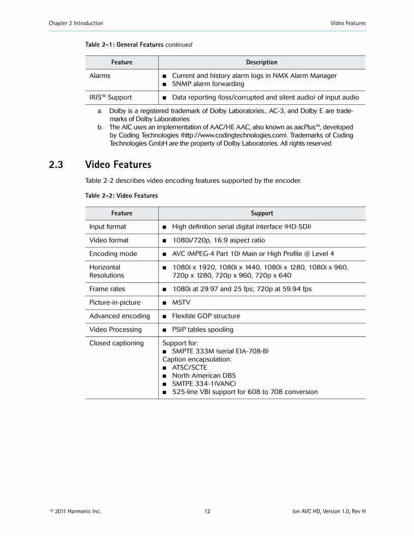
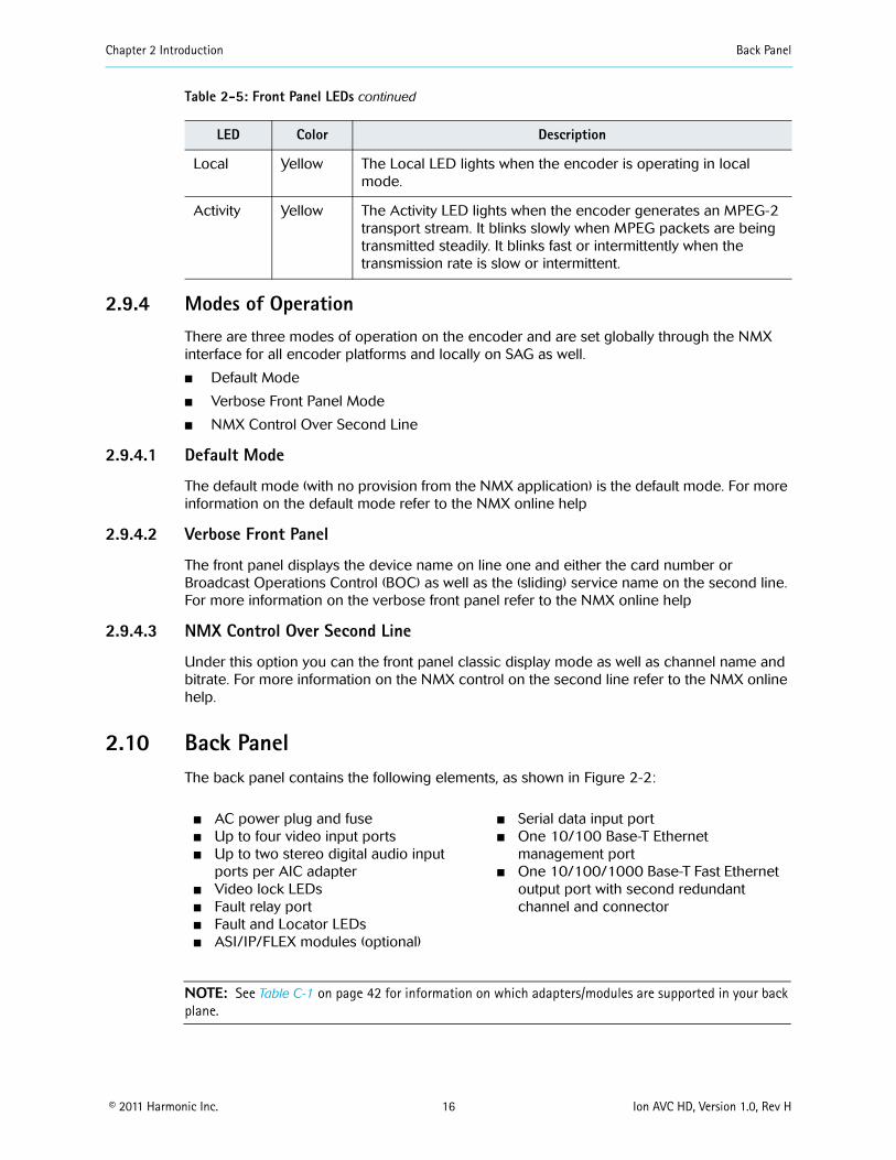
Chapter 2 Introduction Back Panel
copy 2011 Harmonic Inc 16 Ion AVC HD Version 10 Rev H
294 Modes of OperationThere are three modes of operation on the encoder and are set globally through the NMX interface for all encoder platforms and locally on SAG as well
Default Mode
Verbose Front Panel Mode
NMX Control Over Second Line
2941 Default Mode
The default mode (with no provision from the NMX application) is the default mode For more information on the default mode refer to the NMX online help
2942 Verbose Front Panel
The front panel displays the device name on line one and either the card number or Broadcast Operations Control (BOC) as well as the (sliding) service name on the second line For more information on the verbose front panel refer to the NMX online help
2943 NMX Control Over Second Line
Under this option you can the front panel classic display mode as well as channel name and bitrate For more information on the NMX control on the second line refer to the NMX online help
210 Back Panel The back panel contains the following elements as shown in Figure 2-2
NOTE See Table C-1 on page 42 for information on which adaptersmodules are supported in your back plane
Local Yellow The Local LED lights when the encoder is operating in local mode
Activity Yellow The Activity LED lights when the encoder generates an MPEG-2 transport stream It blinks slowly when MPEG packets are being transmitted steadily It blinks fast or intermittently when the transmission rate is slow or intermittent
AC power plug and fuse Up to four video input ports Up to two stereo digital audio input
ports per AIC adapter Video lock LEDs Fault relay port Fault and Locator LEDs ASIIPFLEX modules (optional)
Serial data input port One 10100 Base-T Ethernet
management port One 101001000 Base-T Fast Ethernet
output port with second redundant channel and connector
Table 2-5 Front Panel LEDs continued
LED Color Description
AC Power
Fuse Cover
ASI module
Fault andLocator LEDs
FaultRelayPort
EthernetManagement Port
EthernetOutput Ports
Plug Video Input Ports(optional)FLEX module(optional)
Chapter 2 Introduction Back Panel
copy 2011 Harmonic Inc 17 Ion AVC HD Version 10 Rev H
Figure 2-2 Back panel
2101 AC Power and Fuse The AC power plug accommodates standard IEC 120 VAC and 250 VAC power cords The chassis does not have a power switch The unit powers on automatically when you plug it in
See 356 Connecting the AC Power on page 25 for cabling instructions
The fuse panel is located beside the power plug The encoder requires one slow blow 40 A 250 V fuse 5 x 20 mm See 52 Fuse on page 32 for replacement instructions
2102 Audio Input PortsThe Electra 7000 can be configured with a combination of onboard audio AIC and AHC adapters
21021 AIC Adapter
Each AIC has two digital audio input ports (BNC connectors) The encoder supports up to five AICs Two BNC ports support AES3 or SPDIF to provide the stereo digital audio input to the AIC module
Figure 2-3 illustrates the audio input ports on an AIC adapter
Figure 2-3 Audio Input ports
2103 Video Input Ports The back panel contains up to four video input ports These are BNC coaxial ports that support high definition serial digital video input
Each video input port connects internally to a video processing card The video processing cards are not visible from the encoder back panel
See 353 Connecting the Video Input Cables on page 25 for cabling instructions
Digital Audio Input Port 1
Digital Audio Input Port 2
Chapter 2 Introduction Back Panel LEDs
copy 2011 Harmonic Inc 18 Ion AVC HD Version 10 Rev H
2104 IP Output Port One 101001000 Base-T Ethernet port provides two redundant IP output channels The two RJ-45 connectors are labeled GbE PRI and BKUP
The IP output port supports manual redundancy The port also supports hotwarm standalone redundancy when the primary IP data channel detects a cable disconnection the primary channel stops outputting and the backup channel takes over
In manual redundancy you can enable one channel or both channels If you enable one channel you must manually switch to the other channel after a service-affecting alarm If you enable both channels the encoder outputs the same data from both channels
See 354 Connecting the IP Output Cables on page 25 for cabling instructions Set the IP address and other network information for the IP output ports using NMX
2105 Ethernet Management Port The Ethernet management port labeled ETH is 10100 Base-T and uses an RJ-45UTP cable to connect to an Ethernet network See 355 Connecting the Ethernet Management Cable on page 25 for cabling instructions See A31 Ethernet Management Port on page 35 for pinout information
2106 Fault Relay Port The fault relay port connects to a Form C relay that can switch up to 025 amps at 30 VDC See A32 Fault RelayGPI Ports on page 36 for port pinout and additional information
The encoder energizes the fault relay during normal operation The fault condition is indicated in the same way as the encoderrsquos powered-off condition which is with the relay de-energized You can use this method to correctly identify a power supply failure or loss of input power The signals are normally open or normally closed
NOTE Any alarm causes the fault relay to change to the fault state When multiple alarms accumulate all alarms must be active for the relay state to change
2107 Serial Data Port The serial port can be used for serial 708 input per 333M
211 Back Panel LEDs The following sections describe the back panel LEDs and their functions
Chapter 2 Introduction Back Panel LEDs
copy 2011 Harmonic Inc 19 Ion AVC HD Version 10 Rev H
2111 Main Board LEDsThe back panel contains two LEDs on the main board Table 2-6 describes the LEDs located on the main board
Table 2-6 Rear Panel Main Board LEDs
LED Color Description
Locator Blue The Locator LED lights when this encoder is enabled through NMX Use the Locator LED to help you identify a specific chassis in a rack
Fault Red The Fault LED lights when the application software detects an alarm The front panel and back panel Fault LEDs light at the same time
2112 Audio Port LEDs Each AIC adapter contains a status LED Table 2-7 describes the LED located on each AIC adapter
Table 2-7 Rear Panel Audio Port LEDs
LED Color Description
STAT Blue The Audio Port LED is on during bootup as the audio input card comes online The LED is off during normal operation
2113 Video Lock LEDs Each video port has an associated Video Lock LED Table 2-8 describes the LED located on each video port
Table 2-8 Rear Panel Video Lock LEDs
LED Color Description
Video 1Video 2
Green When illuminated and steady the Video Lock LED indicates that the video signal is locked When off the Video Lock LED indicates that the encoder has lost video sync
copy 2011 Harmonic Inc 20 Ion AVC HD Version 10 Rev H
Chapter 3Installation
This chapter provides detailed instructions for installing a DiviCom Ion AVC HD encoder in a standard 19-inch rack and connecting cables
The chapter describes
How to prepare and unpack the Ion AVC HD
How to install the encoder in a rack
How to update the encoder software
How to connect the cables
31 PreparationYou need a Phillips screwdriver to mount the encoder in a standard 19-inch rack Harmonic ships the necessary rack-mount screws and rack rails
32 Unpacking The encoder comes in a specially designed shipping container that ensures the integrity of your encoder hardware during shipping and handling To avoid damage to the component follow the unpacking instructions that come with the encoder
When you unpack the encoder you should find the following items
Encoder
Standard IEC power cord
Spare air filters
Software warranty agreement
Harmonic ships rack-mounting kits in a separate shipping container
33 Installing the Encoder in a Rack You can install the encoder in different sizes and types of racks For rack assembly instructions consult the manual that came with the rack or the customer service department of the rack manufacturer
This section describes how to mount the encoder in a standard 19-inch rack using the two side-mount rails included in the rack-mounting kit A 30-inch-deep rack with a spacer or chimney between racks with multiple encoders is the recommended rack setup However these rails work for racks that are 30 to 36 inches deep
When you view the rack from the rear the power rail should be installed on the left side
Chapter 3 Installation Installing the Encoder in a Rack
copy 2011 Harmonic Inc 21 Ion AVC HD Version 10 Rev H
331 Rack GuidelinesWhen operating the encoder in the rack ensure that
The ambient temperature around the unit (which may be higher than room temperature) is within the limit specified for the unit
There is sufficient airflow around the unit
Electrical circuits are not overloaded consider the nameplate rating of all the connected equipment
There is overcurrent protection
The equipment is properly grounded
No objects are placed on top of the unit
332 Chassis Warnings for Rack Mounting and Servicing
CAUTION To prevent bodily injury when mounting or servicing this unit in a rack you must take special precautions to ensure that the system remains stable The following guidelines are provided to ensure your safety
This unit should be mounted at the bottom of the rack if it is the only unit in the rack
If the rack will hold a number of units load the rack from the bottom to the top with the heaviest component at the bottom of the rack
If the rack is provided with stabilizing devices install the stabilizers before mounting or servicing the unit in the rack
ATTENTION Pour eacuteviter toute blessure corporelle pendant les opeacuterations de montage ou de reacuteparation de cette uniteacute en casier il convient de prendre des preacutecautions speacuteciales afin de maintenir la stabiliteacute du systegraveme Les directives ci-dessous sont destineacutees agrave assurer la protection du personnel
Si cette uniteacute constitue la seule uniteacute monteacutee en casier elle doit ecirctre placeacutee dans le bas
Si cette uniteacute est monteacutee dans un casier partiellement rempli charger le casier de bas en haut en placcedilant lrsquoeacuteleacutement le plus lourd dans le bas
Si le casier est eacutequipeacute de dispositifs stabilisateurs installer les stabilisateurs avant de monter ou de reacuteparer luniteacute en casier
WARNUNG Zur Vermeidung von Koumlrperverletzung beim Anbringen oder Warten dieser Einheit in einem Gestell muumlssen sie besondere Vorkehrungen treffen um sicherzustellen daszlig das System stabil bleibt Die folgenden Richtlinien sollen zur Gewaumlhrleistung Ihrer Sicherheit dienen
Wenn diese Einheit die einzige im Gestell ist sollte sie unten im Gestell angebracht werden
Bei Anbringung dieser Einheit in einem zum Teil gefuumlllten Gestell ist das Gestell von unten nach oben zu laden wobei das schwerste Bauteil unten im Gestell anzubringen ist
Wird das Gestell mit Stabilisierungszubehoumlr geliefert sind zuerst die Stabilisatoren zu installieren bevor sie die Einheit im Gestell anbringen oder sie warten
333 Airflow The airflow through the encoder is critical for maintaining the proper temperature range Fans in the chassis draw air in through the front bezel and through the encoder The airflow ventilates out the right side (front view)
Chapter 3 Installation Installing the Encoder in a Rack
copy 2011 Harmonic Inc 22 Ion AVC HD Version 10 Rev H
CAUTION Do not obstruct the airflow of the encoder Severe equipment damage can result when the encoder cannot properly exhaust the airflow
334 Attaching the Rack Rails Attach the side-mount rack rails to the rack to hold the encoder in place Figure 3-1 illustrates the parts of the rack rails
Figure 3-1 Rack rails
To attach the rack rails to the rack
1 If needed place a Tinnermantrade speed nut with the nut on the outside of the rack over the holes to which you would like to mount the rails
NOTE Each of the four rack posts requires two speed nuts
2 Position the rack rails so the shelves are toward the inside of the rack
3 Using the 10 screws provided with the encoder screw the mounts into the speed nuts from the inside of the rack using the rack-mount holes that line up with the holes on the rack posts
Figure 3-2 illustrates attaching the rails
Figure 3-2 Attaching the rails to the rack
Chapter 3 Installation Installing Encoder Software
copy 2011 Harmonic Inc 23 Ion AVC HD Version 10 Rev H
CAUTION Make sure to install the rack rails with the shelf at the top of the rail If you install the rail upside down the rail blocks the encoder air vents which can result in overheating the encoder
335 Mounting the EncoderTo mount the encoder in a rack
1 Using both hands grasp the outside corners of the plastic front bezel and slowly pull to detach it from the encoder and expose the mount holes See Figure 3-3
2 Gently slide the encoder to rest on the rack rails
3 Push the encoder back until the rack-mount holes in the front of the encoder line up with the rack posts
4 Insert four screws through the mount holes in the front of the encoder through to the corresponding holes on the rack posts
5 Tighten the screws with a screwdriver
6 Carefully replace the front bezel of the encoder making sure you do not damage the air filters
Rack-mount Holes
Front Bezel
Figure 3-3 Mounting the encoder
34 Installing Encoder SoftwareYour encoder comes from the factory with the latest released software version installed Harmonic periodically releases software updates You can download new software to the encoder using NMX See the NMX online help for instructions for how to download and begin running new encoder software
Chapter 3 Installation Cabling the Encoder
copy 2011 Harmonic Inc 24 Ion AVC HD Version 10 Rev H
35 Cabling the Encoder CAUTION Do not make any cable connections when the power cord is connected You must unplug the power cable to turn off the encoder
The next sections describe how to connect the following cables
Video input
IP output
Ethernet management
Power
351 Back PanelFigure 3-4 shows a sample back panel of the DiviCom Ion AVC HD encoder configured with optional ASI and FLEX modules
AC Power
Fuse Cover
ASI module
Fault andLocator LEDs
FaultRelayPort
EthernetManagement Port
EthernetOutput Ports
PlugVideo Input Ports
(optional)FLEX module(optional)
Figure 3-4 Back panel
352 Connecting the Audio Input Cables An encoder may have up to five audio input cards (AICs) each of which has two stereo digital audio ports or up to five audio adapters (AHC AHC-RAC or AHC-561) each of which has four stereo digital audio ports When the encoder is equipped with an AHC-RAC used to support native AES input only three of the four digital audio ports on a card can be used at one time
To connect the audio cables
Connect a coaxial cable with a BNC connector from the digital audio port to the audio source On each AIC the digital audio ports are labeled DGTL AUD1 and DGTL AUD2 On each AHC the digital audio ports are labeled DGTL AUD1 DGTL AUD2 DGTL AUD3 and DGTL AUD4 For multichannel audio use three cables to connect the surround mix connecting LR to DGTL AUD1 CLfe to DGTL AUD2 and LsRs to DGTL AUD3 which maps the channels to AES3 pairs as defined by SMPTE 320M If the encoder is equipped with an AHC-RAC then one more stereo pair can be connected to DGTL AUD4 Otherwise the fourth connector is not used
Chapter 3 Installation Cabling the Encoder
copy 2011 Harmonic Inc 25 Ion AVC HD Version 10 Rev H
353 Connecting the Video Input Cables Your encoder has up to four video input ports The video input ports accept serial digital video To connect the video cables
1 Connect a coaxial cable with a BNC connector from the first video source to the Video 1 port on the encoder
2 Continue connecting the additional video sources to the remaining video ports
354 Connecting the IP Output Cables The encoder has one IP output port with two redundant channels and two RJ-45 connectors
NOTE The network hosting the IP output traffic must be a different network from your management network and must be configured with a different IP address
NOTE Harmonic recommends that shielded and grounded Ethernet cables be used on all Ethernet ports
To connect the IP output cables
1 Connect an Ethernet cable from the primary IP output port to a port on a network switch or router not a hub
2 Optionally connect the backup IP output port to a different switch or router to facilitate redundancy
3 Configure the Ethernet switch to support autonegotiation by setting each port to ldquoset speed autordquo and ldquoset duplex autordquo
NOTE Failure to properly configure the Ethernet switch could result in a mismatch between the IP output and the switch
Harmonic supports 101001000 Base-T and is fully compliant with IEEE 8023 8023u and 8023as standards
355 Connecting the Ethernet Management Cable The Ethernet management port allows communication between NMX and the encoder
To connect the Ethernet management cable
Connect an RJ-45UTP cable from the encoderrsquos back panel 10100 Base-T port to a port on an Ethernet switch
NOTE The network hosting the IP output traffic should be a different network from your management network
356 Connecting the AC Power The encoder AC power supply uses autosensing to adjust to different incoming voltages
CAUTION This product relies on the buildingrsquos electrical installation for short-circuit (overcurrent) protection Ensure that a fuse or circuit breaker no larger than 120 VAC 20 A US (240 VAC 20 A international) is used on the phase conductors (all current-carrying conductors)
Chapter 3 Installation Cabling the Encoder
copy 2011 Harmonic Inc 26 Ion AVC HD Version 10 Rev H
ATTENTION Pour ce qui est de la protection contre les courts-circuits (surtension) ce produit deacutepend de lrsquoinstallation eacutelectrique du local Veacuterifier qursquoun fusible ou qursquoun disjoncteur de 120 V alt 20 A US maximum (240 V alt 20 A international) est utiliseacute sur les conducteurs de phase (conducteurs de charge)
WARNUNG Dieses Produkt ist darauf angewiesen daszlig im Gebaumlude ein Kurzschluszlig-bzw Uumlberstromschutz installiert ist Stellen sie sicher daszlig eine Sicherung oder ein Unterbrecher von nicht mehr als 240 V Wechselstrom 20 A (bzw in den USA 120 V Wechselstrom 20 A) an den Phasenleitern (allen stromfuumlhrenden Leitern) verwendet wird
To connect the power cord
Connect the power cord to the power plug on the encoder back panel and connect the power cord to the power outlet
CAUTION The power supply cord is used as the main disconnect device Ensure that the socketoutlet is locatedinstalled near the equipment and is easily accessible
ATTENTION Le cordon drsquoalimentation est utiliseacute comme interrupteur geacuteneacuteral La prise de courant doit ecirctre situeacutee ou installeacutee agrave proximiteacute du mateacuteriel et ecirctre facile drsquoacceacutes
WARNUNG Das Netzkabel dient als Netzschalter Stellen sie sicher das die Steckdose einfach zugaumlnglich ist
Power Supply Cord Notice
CAUTION This unit has more than one power supply connectionrsquo all connections must be removed to remove all power from this unit
ATTENTION Cette uniteacute est eacutequipeacutee de plusieurs raccordements dalimentation Pour supprimer tout courant eacutelectrique de luniteacute tous les cordons dalimentation doivent ecirctre deacutebrancheacutes
WARNUNG Diese Einheit verfuumlgt uumlber mehr als einen Stromanschluszlig um Strom gaumlnzlich von der Einheit fernzuhalten muumlssen alle Stromzufuhren abgetrennt sein
Laser warning
Warning Class 1 laser product
Attention Produit laser de classe 1
Warnung Laserprodukt der Klasse 1
copy 2011 Harmonic Inc 27 Ion AVC HD Version 10 Rev H
Chapter 4Operating the Encoder
After installing the encoder in a rack and connecting the cables as described in Chapter 3 Installation configure the encoder platform and services
The chapter describes
How to use NMX Digital Service Manager to configure the Ion AVC HD
How to use the Ion AVC HD front panel
41 Operating with NMX Digital Service ManagerWhen you use NMX Digital Service Manager to manage the encoders in your network you perform all encoder configuration including IP address assignment in NMX You do not need to do any configuration from the encoder front panel
See the NMX online help for instructions for adding an encoder to an NMX network group You will need to know the encoder MAC address when you add the encoder to a network group See 424 Viewing the Encoder MAC Address on page 29 for instructions for viewing the MAC address in the front panel display
42 Using the Front Panel You can perform some initial network configuration from the encoder front panel From the front panel you can set the encoderrsquos IP address default gateway and subnet mask and you can view the encoderrsquos MAC address and serial number
421 The Keypad The keypad on the local control panel provides the following functions
Access to the menus
Navigation through the menu hierarchies to their parameters
Editing capabilities
Figure 4-1 shows the keypad
Hot Keys Navigation andFunction Keys
Alphanumeric Keys
Figure 4-1 Front panel keypad
Seven hot keys provide immediate access to the encoder menus The Network and Help hot keys are currently active The other hot keys are reserved for future use
Chapter 4 Operating the Encoder Using the Front Panel
copy 2011 Harmonic Inc 28 Ion AVC HD Version 10 Rev H
Navigation and function keys located to the right of the hot keys provide a tool for navigating through the menu hierarchies and changing parameter values Use the alphanumeric keys to enter new values
422 Front Panel Display
The two-line 20-character vacuum fluorescent display (VFD) shows the menus parameters and options As illustrated in Figure 4-2 line 1 of the local control panel display shows the menu path for the currently selected option To represent a path the VFD displays each submenu as two or more letters and a colon
Line 2 of the display shows the second line of a help message or a parameter value To change this value you must enter the new value using the keypad
NTWK Control IPParameter Requires
Value to be Edited
Value Setting
19216824101
Figure 4-2 Setting a value in the front panel display
A blinking cursor shows the current value A steady cursor shows the value being edited
Press the Help key to display an online message for the currently selected menu item
423 Setting the Encoder Network PropertiesBefore you can begin to configure the encoder you must set the encoder IP address subnet mask and default gateway The encoder ships with a default IP address based on the encoder serial number The default subnet mask is 255000 and the default gateway address is 10001
4231 Setting the IP Address
To set the encoder management port IP address
1 Press the NTWK hot key
The VFD display shows NTWK Configuration
2 Press the
v key to navigate to NTWK Control IP
3 Press Enter
4 Enter the IP address using the alphanumeric keys
TIP To enter a period press the Shift key and the 0 key
5 When you finish press Enter
Do not exit the Network menu because you can set the other properties from here
Chapter 4 Operating the Encoder Using the Front Panel
copy 2011 Harmonic Inc 29 Ion AVC HD Version 10 Rev H
4232 Setting the Subnet Mask
To set the subnet mask
1 Press the
v key to navigate to NTWK Control Subnet
2 Press Enter
3 Enter the subnet mask using the alphanumeric keys
TIP To enter a period press the Shift key and press the 0 key
4 When you finish press Enter
4233 Setting the Default Gateway Address
To set the gateway address
1 Press the
v
key to navigate to NTWK Gateway
2 Press Enter
3 Enter the default gateway using the alphanumeric keys
TIP To enter a period press the Shift key and press the 0 key
4 When you finish press Enter
5 Press Esc to exit the Network menu
424 Viewing the Encoder MAC Address You can view the encoder MAC address from the front panel
To view the encoder MAC address
1 Press the NTWK hot key
2 Press the
v
key several times to navigate to NTWK Control MAC
The MAC address appears beneath the parameter name
3 Press Esc to exit the parameter
425 Viewing the Encoder Serial NumberYou can view the encoder serial number from the front panel
To view the encoder serial number
1 Press the STAT hot key
2 Press the
v
key to navigate to STAT Serial Number
The serial number appears beneath the parameter name
3 Press Esc to exit the parameter
Chapter 4 Operating the Encoder Licensing Information
copy 2011 Harmonic Inc 30 Ion AVC HD Version 10 Rev H
43 Licensing InformationLicensing is required for some encoding features and you cannot enable those features without the appropriate licensing You can add licenses to your system at any time using the SAG (Web GUI) You must acquire licenses from Harmonic When licenses expire streams will continue to flow as configured but cannot be modified or re-enabled if disabled for any reason Streams that include features under license will raise alarms when their licensing expires Alarms will also be raised to advise you that licensing is required for a given feature if that feature is blocked Also any attempted changes after a license expires may be service affecting and other operations such as redundancy may not operate properly For additional information on using the Configuration Manager for licensing operations refer to your encoderrsquos online help
Under the Licensing tab (on Platform Configuration page) you can
Apply license keys that have been created and sent to you by Harmonic in a lic license file The license file is unique to a specific encoder and can be used on that encoder only once When you apply a license the system scans the encoder platform for the matching devicefeature and binds the license key to that encoder One lic file may contain multiple license keys Every key in the lic file will be applied One license key may unlock multiple instances of a feature There is no undo for applying licenses but you can delete them
Delete a license key and save the deletion receipt for return to Harmonic If you want to remove a license key from one device to use it on another you must delete it When you delete a key the device releases it and a unique deletion receipt is created This receipt must be sent to Harmonic so that the deleted license can be made available in the license database for use in a different encoder There is no undo for deletion You must provide the deletion receipt to Harmonic to make the license available for use again
View the current licenses that are on the encoder platform
To apply licenses
If you ordered a new license you received a file To install it on this encoder follow these steps
1 Click the Add license button The license Loader window opens
2 Type in the path and file name where you saved the new license file or use the Browse button and navigate to it
3 Click the Transfer button The encoder applies all the license keys that are in the lic file and binds them to the encoder The new licenses appear in the license table
4 Disable then re-enable the affected streams if applicable
To delete licenses
Contact Harmonic customer support for more information
copy 2011 Harmonic Inc 31 Ion AVC HD Version 10 Rev H
Chapter 5Maintenance and Troubleshooting
This chapter describes
How to maintain and replace the air filters and fuse
How to contact Harmonic Support
51 Air Filters The encoder uses two air filters to minimize dust and dirt in the circuitry and components in the chassis These filters are made of flexible compressed fiber spun from urethane foam Installed in the front of the encoder the filters are fire retardant and conform to UL 900 Class II specifications
The bezel filter is located inside the front bezel on the left side Figure 5-1 shows the dimensions of the bezel filter The notches on the left side and the cutouts in the middle can fit on either side of the front bezel mounting posts
532 inches
164 025 inchesinches
Figure 5-1 Bezel filter (front view)
The keypad filter is located behind the front panel keypad Figure 5-2 shows the keypad filter
645 inches
025 inches
164inches
Figure 5-2 Keypad filter (front view)
511 Maintaining the Air Filters The operating environment of the encoder plays a large factor in determining the life of the air filters Encoders that operate in dusty and dirty surroundings require more frequent inspections and filter cleaning than those operating in cleaner environments
Inspect and clean the filters with a frequency that is appropriate to the environment in which the encoder operates Harmonic recommends inspecting and cleaning the filters every six weeks to ensure proper airflow through the chassis
To clean dust and dirt from the filters you can use a vacuum cleaner to remove the dirt or you can rinse the filters in water You can also use soaps or mild detergents on the filters If you rinse the filters in water make sure that you squeeze the excess water from them before reinstalling them in the encoder You might need to order replacement filters if the filters become too dirty over time
Chapter 5 Maintenance and Troubleshooting Fuse
copy 2011 Harmonic Inc 32 Ion AVC HD Version 10 Rev H
512 Removing and Replacing the Air Filters You do not need to turn off the encoder when removing and replacing the air filters
5121 Removing and Replacing the Bezel Filter
To remove the front left filter from behind the front bezel
1 Grasp each side of the encoderrsquos front bezel with your hands
2 Carefully remove the front bezel by pulling it away from the encoder
3 Remove the filter from inside the front bezel
4 Inspect the air filter for dirt and clean it if necessary
NOTE When the filter is new its color is medium charcoal As dust and dirt collect in the porous filter material the filterrsquos color gradually changes to brown then an ash color
5 Replace the filter inside the front bezel Place the filter so that the long horizontal slot is at the bottom edge Carefully place the cutouts in the filter around the bezel mounting posts
6 Carefully replace the front bezel on the encoder making sure the filter does not fall out of the bezel
5122 Removing and Replacing the Keypad Filter
To remove the air filter from behind the keypad
1 Grasp each side of the encoder front bezel with your hands
2 Carefully remove the front bezel by pulling it away from the encoder
Note the location of the filter The keypad is screwed onto the front of the encoder through four mounting posts Cutouts on the filter wrap around the four posts and the right side of the filter extends past the keyboard
3 Remove the filter by pulling the left side of the filter up and away from the keyboard mounting posts then pulling up the right side
4 Inspect the air filter for dirt and clean it if necessary
5 Replace the filter by inserting the right side of the filter behind the keypad with the vertical slots around the mounting posts
6 Insert the left side of the filter placing the horizontal cutouts around the mounting posts
7 Carefully replace the front bezel on the encoder making sure the filter does not fall out of the bezel
52 Fuse Encoders use a slow blow 40 A 250 V fuse 5 x 20 mm The fuse is located on the back panel beside the power input A spare fuse is located in the fuse cover shown in Figure 5-3
Fuse cover
Figure 5-3 Fuse cover and AC power input
Chapter 5 Maintenance and Troubleshooting Contacting Harmonic Support
copy 2011 Harmonic Inc 33 Ion AVC HD Version 10 Rev H
521 Replacing the FuseTo replace the fuse
1 Unplug the power cord from the chassis
DANGER You must disconnect the power cord before removing the fuse
2 Pull down the fuse cover on the back panel
3 Remove the old fuse
4 Install the new fuse
DANGER Always replace the fuse with a fuse of the same rating and type Using a different fuse voids the Harmonic warranty and could result in fire or other electrical damage
5 Replace the fuse cover
6 Plug in the encoder
53 Contacting Harmonic SupportThe Harmonic Customer and Technical Support groups are available to help you with any questions or problems you may have regarding Harmonic products
For assistance from within the US and Canada call toll free
1888MPEGTWO (6734896)
For assistance from outside the US and Canada call
14084906477
The fax number is 4084906770
The email address is techhelpharmonicinccom
The corporate address for Harmonic Inc is
Harmonic Inc 549 Baltic Way Sunnyvale CA 94089 USA Attn Customer Support
The corporate telephone numbers for Harmonic Inc are
Tel 18007881330 (from the US and Canada) Tel +14085422500 (outside the US and Canada) Fax+14084906708
The web address for Harmonic Inc is wwwharmonicinccom
copy 2011 Harmonic Inc 34 Ion AVC HD Version 10 Rev H
Appendix AEncoder Specifications
This appendix contains a comprehensive list of the environment and physical characteristics of the encoder electrical specifications and information about the pinouts for the input and output ports
A1 Environment Specifications Table A-1 lists environment specifications for the encoder
Table A-1 Environment Specifications
Parameter Specification
Size 445 cm x 4826 cm x 6069 cm (175 in x 19 in x 24 in)
Weight 11 kg (24 lb)
AC Power
AC 100-240V (auto ranging)
47 to 63 Hz
1 channel (ELC-7011) 108 W 2 channel (ELC-7022) 162 W 3 channel (ELC-7033) 216 W 4 channel (ELC-7044) 270 W
63A 250V fuse 5 x20mm
Temperature
5 to 40 degC (41 to 104 degF)
ndash20 to +80 degC (ndash4 to +176 degF)
Humidity
lt 95 noncondensing
lt 95 noncondensing
Altitude
lt 15000 feet (4572 meters)
lt 40000 feet (12192 meters)
Shock and Vibration
Passes the impact compression and vibration requirements of ASTM D4169-94 Distribution Cycle 13 Assurance Level 1
Passes NEBS Office Vibration Test while operating (01G sine sweep 5 to 100 Hz 3 axis)
Input voltage range
Line frequency
Typical consumption
Fuse
Operating
Storage
Operating
Storage
Operating
Storage
Packaged
Operating
Appendix A Encoder Specifications Port Specifications
copy 2011 Harmonic Inc 35 Ion AVC HD Version 10 Rev H
A2 Port Specifications Table A-2 lists the specifications for the back panel port connections For port locations see the illustration of the back panel on Figure 3-4 on page 24
Table A-2 Port Specifications
Port Connection Specification
Video input port
Serial DigitalSignal format per SMPTE 292M
75 Ω unbalanced
BNC
Ethernet management port
10100 Base-T
8023
RJ-45
Input serial port Reserved for future use
Ethernet output port
101001000 Base-T
MPEG-4 over IP
RJ-45
Fault relay port Capable of switching 025 amps at 30 VDC
Phoenix 1881383
A3 Port Pinouts The following sections describe the Ethernet management and fault relay port pinouts
A31 Ethernet Management Port The Ethernet management port is 10100 Base-T and uses an RJ-45UTP port to connect to an Ethernet network Use this port to manage the encoder with NMX See 355 Connecting the Ethernet Management Cable on page 25 for cabling instructions
Table A-3 lists the pinouts for the RJ-45 Ethernet port
Protocol
Impedance
Connector type
Type
Protocol
Connector type
Type
Protocol
Connector type
Mating connector type
Table A-3 Ethernet Management Port Pinout
Pin Signal
1 Transmit data (TD) +
2 Transmit data (TD) ndash
Appendix A Encoder Specifications Port Pinouts
copy 2011 Harmonic Inc 36 Ion AVC HD Version 10 Rev H
A32 Fault RelayGPI Ports A contact closure is a physical connection between two platforms that define the state of the platform by being either on or off
Both NMX and SAG provide alarm management and redundancy for third party devices through contact closure monitoring Additionaly the contact closure on the Electra and Ion-based encoders can also be used as DPI inputs to the encoder A contact closure is a physical connection (Figure A-1) between two platforms that define the state of the platform by being either on or off Table A-4 lists the fault relay pinouts Individual wires need to be inserted into the contacts and grounded to the ground pin to activate a contact closure When configured in the DPI properties page (of either NMX or the SAG) an SCTE35 message is sent out when that pin is set to low Each is independent and can be provisioned to any one channel and multiple available channels
The fault relay port connects to a Form C relay that can switch up to 025 A at 30 VDC
Table A-4 Fault RelayGPI Port Pinout
Pin Connection
1 Normally closed (NC)
2 Normally open (NO)
3 Common (CM)
4 GPI contact 1
5 GPI contact 2
6 GPI contact 3
7 GPI contact 4
8 Ground (GND)
3 Receive data (RD) +
4 Not connected
5 Not connected
6 Receive data (RD) ndash
7 Not connected
8 Not connected
Table A-3 Ethernet Management Port Pinoutcontinued
Pin Signal
Appendix A Encoder Specifications Port Pinouts
copy 2011 Harmonic Inc 37 Ion AVC HD Version 10 Rev H
Figure A-1 Fault RelayGPI Ports
copy 2011 Harmonic Inc 38 Ion AVC HD Version 10 Rev H
Appendix BAudio and Video Specifications
B1 AIC FeaturesThe AIC adapter accepts analog (balanced or unbalanced) discrete AES3SPDIF digital and AES3 embedded in serial digital video inputs For analog and discrete AES3 inputs sampling frequencies of 48 kHz 441 kHz and 32 kHz are supported Embedded digital is supported only for 48 kHz sampling which must be synchronous to the video
Table B-1 lists the AIC features for each coding mode including the supported sampling frequencies and ES bit rates
Table B-1 AIC Features
AIC Feature Coding Mode SamplingFrequency
ES Bit RatesSupported (Kbps)
MPEG-1 Layer II compression
Single channel (10) 32 kHz 441 kHz 48 kHz
32 48 56 64 80 96 112 128 160 192
Dual channel (1+1) Stereo channel (20) Joint stereo channel
32 kHz 441 kHz 48 kHz
64 96 112 128 160 192 224 256 320 384
MPEG-1 Layer II compression SPPC (separate PID per channel)
Single channel (10) 32 kHz 441 kHz 48 kHz
32 48 56 64 80 96 112 128 160 192
Dolby Digital (AC-3) compression
Single channel (10) 32 kHz 441 kHz 48 kHz
56 64 80 96 112 128 160 192 224 256 320
384 448a 512a 576a
640a
Stereo channel (20) 32 kHz 441 kHz 48 kHz
96 112 128 160 192
224 256 320 384 448a
512a 576a 640a
Dolby Digital (AC-3) passthrough
Up to 51 channels (32+LFE professional 16-bit mode)
32 kHz441 kHz48 kHz
56b 80b 96 112 128 160 192 224 256 320 384
448a 512a 576a 640a
Up to 51 channels (32+LFE professional 32-bit mode)
32 kHz441 kHz48 kHz
256 320 384 448a 512a
576a 640a
Appendix B Audio and Video Specifications AIC Features
copy 2011 Harmonic Inc 39 Ion AVC HD Version 10 Rev H
Note the following limitations
ATSC Standard A53 specifies that only 48 kHz sampling may be used and that ES bit rates must be less than or equal to 384 Kbps for a complete service It also specifies that a two-channel dialog-only service must be less than or equal to 192 Kbps Total ES rates for all services must be less than or equal to 512 Kbps
Embedded audio must be 48 kHz sampling and synchronous with the video See SMPTE 272M for definitions
MPEG AAC and HE AAC can be placed into the output Transport Stream encapsulated in either of two methods
ADTS
ADTS is an acronym for ldquoAudio Data Transport Streamrdquo This is the default used if the user selects MPEG-2 AACHE AAC ADTS is assigned a stream type value of 0x0F
LATMLOAS
LATM is an acronym for rdquoLow Overhead Audio Transport Multiplexrdquo LOAS is an acronym for rdquoLow Overhead Audio Streamrdquo and furnishes an outer wrapper for LATMs inner wrapper of the raw audio Elementary Stream syntax MPEG-4 AAC and HE AAC bitstreams are encapsulated as LATMLOAS and assigned a stream type value of 0x11
Encapsulation mode is controlled by selecting rdquoMPEG-2rdquo or rdquoMPEG-4rdquo as required
MPEG HE AAC compression
Single channel (10) 32 kHz441 kHz48 kHz
32 48 56 64 96
Dual channel (1+1) Stereo channel (20) Joint stereo channel
32 kHz441 kHz48 kHz
32 48 56 64 96 112 128
MPEG AAC compression
Single channel (10) 32 kHz441 kHz48 kHz
32 48 56 64 96 112 128 182 192
Dual channel (1+1) Stereo channel (20) Joint stereo channel
32 kHz441 kHz48 kHz
64 96 112 128 182 192 224 256 320 384
a These rates are not compliant with A53b These rates are valid for 10 coding only
Table B-1 AIC Features continued
AIC Feature Coding Mode SamplingFrequency
ES Bit RatesSupported (Kbps)
Appendix B Audio and Video Specifications Dolby Digital (AC-3) Audio
copy 2011 Harmonic Inc 40 Ion AVC HD Version 10 Rev H
B2 Dolby Digital (AC-3) Audio The Ion AVC HD supports Dolby Digital (AC-3) native audio encoding AIC-equipped encoders support native two-channel Dolby Digital (AC-3) compression AIC-equipped encoders also support Dolby Digital (AC-3) 51 in passthrough mode
NOTE Harmonic supports Dolby Digital (AC-3) passthrough rates of 96 to 640 Kbps and native Dolby Digital (AC-3) rates of 56 to 640 Kbps
Table B-2 lists the bit rates for the sample frequencies of 48 kHz 441 kHz and 32 kHz
Table B-2 Dolby Digital (AC-3) Audio Bit Rates
Audio Bit Rate (Kbps)
Audio without PCR Audio with PCR
48 kHz 441 kHz 32 kHz 48 kHz 441 kHz 32 kHz
56 658 605 627 658 605 627
64 752 691 689 752 691 689
80 846 864 877 846 864 877
96 1034 1036 1003 1034 1036 1065
112 1222 1209 1191 1222 1209 1191
128 1316 1382 1316 1410 1382 1379
160 1692 1641 1692 1692 1727 1692
192 1974 1986 2005 2068 1986 2005
224 2350 2332 2319 2350 2332 2319
256 2632 2677 2632 2726 2677 2695
320 3290 3282 3321 3384 3368 3321
384 3948 3973 3948 4042 3973 3948
448 4606 4664 4637 4606 4664 4637
512 5264 5268 5264 5264 5268 5264
576 5922 5959 5891 5922 5959 5953
640 6580 6564 6580 6580 6564 6580
NOTE Changing from non-single-channel mode to single-channel mode provisions the transport bit rate automatically
When you change between single-channel and non-single-channel modes the encoder automatically provisions the bit rate to the closest available bit rate In some cases this means the bit rate is lower because provisioning does not increase the bit rate defined for the port Therefore changing the coding mode from non-single-channel mode to any of the four highest bit rates causes the encoder to provision the bit rate to 192 Kbps
Appendix B Audio and Video Specifications Video Specifications
copy 2011 Harmonic Inc 41 Ion AVC HD Version 10 Rev H
In the case of the three lowest bit rates when you change from single-channel to non-single-channel mode because the bit rate is the lowest available the encoder provisions to the next highest available bit rate 64 Kbps If you set the bit rate to 80 Kbps and then change the coding mode to non-single-channel the encoder provisions the bit rate to 64 Kbps
B3 Video Specifications The encoder is equipped to handle high definition (HD) serial digital input (SDI)
Table 5-1 Video Specifications
Feature Specification Comments
Input formats Serial digital component High definition serial digital interface (HD-SDI) per SMPTE 292M
VITC support 1080i 30MB 720p 60MB
Import formats supported in HD
B4 VITC SupportThe Ion AVC HD supports extraction of Vertical Interval Time Code (VITC) data placed into VANC or HANC per SMPTE RP188 The VITC data is used to synchonize DPI events on hoth HD and SD encoders HD encoders receive VITC input carried in the Vertical Ancillary data space (VANC) or Horizontal Ancillary data space (HANC) of a 292MB stream
copy 2011 Harmonic Inc 42 Ion AVC HD Version 10 Rev H
Appendix CEncoder Back Panel Slot Locations
C1 Adapter Configurations for All EncodersFigure C-1 represents the back panel of an encoder Table C-1 shows the slot number and the modules that can be installed in encoders that are not associated with a FLEX module Table C-2 shows the slot number and the modules associated with the FLEX module that can be installed NMX uses the slot number to differentiate between adapters of the same type within the encoder
Slot 2
Slot 1 Slot 3
Slot 4 FLEX
Main Board
Slot 5 FLEX
Figure C-1 Slot numbers
Table C-1 shows the adaptersmodules software support and configuration recommendations for non-FLEX based encoders
Table C-1 Supported adaptersmodules and configuration recommendations for this encoder
Adapter Slot Notes
AIC Any slot (1-5 adapters per chassis)
AHC-RAC Any slot (1-5 adapters per chassis)
AHC-561 Slots 1- 4 (1-4 adapters per chassis) Not supported on slot 5 Supported only via NMX
ASI Output Slot 5 without a FLEX module Slot 2 with a FLEX module (1 adapter per chassis)
Only the first two ports are active and are electrical duplicates of each other
AB Power Input switch
Slots 1 and 3 (both)
C11 Additional Adapter Configurations for FLEX-based EncodersTable C-2 lists the adapter configurations available for FLEX-based encoders
Table C-2 FLEX Module Options (for use with FLEX module)
Card Option Notes
FLEX Slot 4 must be populated first slot 5 second (1-2 adapters per chassis)
Requires CPC revision 105 or higher see Viewing the Control Board (CPC) Revision Information on page 43
GbE Slot 1 only (1 adapter per chassis)
Used with FLEX module for input only
Appendix C Encoder Back Panel Slot Locations Adapter Configurations for All Encoders
copy 2011 Harmonic Inc 43 Ion AVC HD Version 10 Rev H
NOTE ASI Input adapters (used with FLEX module) and ASI Output adapters utilize the same hardware but perform different functions based on 1) the slot number and 2) if a FLEX module is installed If installed in slots 2 or 5 the ASI adapter is always an output If a FLEX module is installed an ASI adapter installed in slots 1 or 3 is an input
C12 Viewing the Control Board (CPC) Revision Information1 From the Platform tab click on the Platform link
2 Click on the Control Board (CPC) link
The Control Board (CPC) Configuration page appears
Click on the Maintenance tab to examine the version information
ASI Input Slot 1 (typical) slot 3 if slot 1 isalready in use (1 card perchassis) For FLEX only chassisthe FLEX module goes into slot4 and 5 Slot 4 must bepopulated first For baseband andcompressed mixed inputencoders the FLEX module canbe either slot 4 or 5 ASI inputadapters cannot use slot 4 as itis used for first FLEX module
ASI input is currently only forFLEX module ASI in slots 1 3and 4 appears as an input card
RF 8VSB Slot 1 (typical) or slot 3 if slot 1 is already in use or slot 2 if slots 1 and 3 are already in use (1 adapter per chassis)
Used with FLEX module for input only
Table C-2 FLEX Module Options (for use with FLEX module)
Card Option Notes
copy 2011 Harmonic Inc 44 Ion AVC HD Version 10 Rev H
Appendix DBoot Sequence
This appendix describes the encoder boot sequence including the messages that appear on the local control panel display
D1 Local Control Panel Display Messages during BootupMessages on the local control panel indicate progress during boot-up During a successful boot many events occur so quickly you cannot see the messages The following sections describe the messages that you can see during boot attempts
NOTE During the boot sequence do not press any key on the keypad
The following sequence describes the display on the vacuum fluorescent display (VFD) during a successful startup
Power on
VFD line 1 = Harmonic Inc VFD line 2 = System Loading
Begin loading
VFD line 1 = Divicom Ion AVC HD VFD line 2 = System Loading
Booting
VFD line 1 = Divicom Ion AVC HD VFD line 2 = Loading xxxxxxxxelf
Finished
VFD line 1 = Divicom Ion AVC HD VFD line 2 = Multichannel Encoder
D2 Other Local Control Panel Display MessagesThe local control panel displays messages for other types of restarts including a system reset and loading new software
D21 Resetting the Encoder When you reset the encoder from NMX a message on the VFD shows that the encoder has been reset The encoder uses the boot file on the hard drive when you reset it
Reset from NMX
VFD line 1 = Bye bye VFD line 2 =
After power cycle
VFD line 1 = Harmonic Inc VFD line 2 = System Loading
Begin loading
Appendix D Boot Sequence Other Local Control Panel Display Messages
copy 2011 Harmonic Inc 45 Ion AVC HD Version 10 Rev H
VFD line 1 = Divicom Ion AVC HD VFD line 2 = System Loading
Booting
VFD line 1 = Divicom Ion AVC HD VFD line 2 = Loading xxxxxxxxelf
Finished
VFD line 1 = Divicom Ion AVC HD VFD line 2 = Multichannel Encoder
D22 Loading New Software You can download new software to an encoder using NMX After downloading the software restart the encoder to begin using the new software The following messages appear
Begin loading
VFD line 1 = Divicom Ion AVC HD VFD line 2 = System Loading
Booting
VFD line 1 =Divicom Ion AVC HD VFD line 2 = Loading xxxxxxxxelf
Finished
VFD line 1 = Divicom Ion AVC HD VFD line 2 = Multichannel Encoder
copy 2011 Harmonic Inc 46 Ion AVC HD Version 10 Rev H
Appendix EWiring the ndash48 VDC Power Supply
If your encoder has the optional ndash48 VDC power supply follow these steps to wire the power supply
E1 Getting StartedBefore you begin wiring the ndash48 VDC power supply make sure that you provide the necessary overcurrent protection wires and power connector
E2 Power Source SpecificationsThe DC power source feeding the encoder must meet the following requirements
Electrically isolated from any AC power source
Positive ground The Positive bus of the DC power source must be reliably connected to the Ground bus
Each feed-pair must provide a continuous supply of power that meets the following specifications
Table E-1 Power Source Specifications
Parameter Specification
Voltage 40ndash60 VDC
Max operating current 8 amps
Max input surge current
20 amps
E3 Overcurrent ProtectionTo provide overcurrent protection
Provide overcurrent protection devices as part of each rack housing encoders
Locate a readily accessible disconnect device between the DC power source and the encoder
Use a 10-amp double-pole fast trip DC-rated disconnect device for each DC power connector
NOTE Overcurrent protection devices must meet applicable national and local electrical safety codes and be approved for the intended application
E4 Wiring RequirementsThe encoder is connected to the DC power source using three wires
ndashVin
GND
Appendix E Wiring the ndash48 VDC Power Supply Power Connector
copy 2011 Harmonic Inc 47 Ion AVC HD Version 10 Rev H
+Vin
Although Harmonic provides the power input connector with the encoder you must supply the wires
The wires to be used must comply with the following specifications
Table E-2 Recommended Wire Specifications
Parameter Specification
Suitable conductor material Copper only
ndashVin and +Vin wires 16 AWG rating
Ground cable 16 AWG rating
Cable insulation rating Minimum 80 C low smoke fume (LSF) flame retardant
Cable type Must comply with at least one of the following standards
Branch circuit cable insulation color
Per applicable national electrical codes
E5 Power ConnectorThe encoder is supplied with a special DC power connector plug that matches the DC power socket on the back of the encoder
This connector is made by WAGO model number 231-103037-000
Use only the original connector for connecting the encoder to the DC power source Contact Harmonic Technical Support if you want to use any other type of connector
The following figure shows the connector and its strain relief housing
Figure E-1 CableStrain Relief Housing
E6 Assembling the DC Input Power CableTo assemble the DC input power cable
1 Prepare the power wires as specified in E4 Wiring Requirements on page 46
2 Use the disconnect device to make sure that the power supply from the DC power source to the cables is switched off
UL 1581 (VW-1) - UL style 1028 or equivalent EEE 383 EEE 1202-1991
Appendix E Wiring the ndash48 VDC Power Supply Assembling the DC Input Power Cable
copy 2011 Harmonic Inc 48 Ion AVC HD Version 10 Rev H
CAUTION Turn off the power before proceeding with these instructions
3 Unplug the WAGO power connector from the power socket on the encoder back panel
4 Identify the three wires coming from the DC power source that are used in the connection to the expansion unit
ndashVin
+Vin
GND
5 Strip up to 03 inches (8 mm) of insulation from each of the wires coming from the DC power source
Do not strip more than this length from each wire Stripping more leaves uninsulated wire exposed outside the DC connector after the assembly is complete
6 Insert a small screwdriver into the rectangular hole directly above the hole in the DC connector where you want to insert the first cable and press down on the screwdriver
This opens the cage clamp for this section of the DC plug connector
NOTE WAGO also sells tools specifically designed to open cage clamps easily For more information either visit the WAGO web site at wwwwagocom or call WAGO at 1-800-346-7245 and request information about items 210-250 or 231-131
7 Feed the exposed section of the wire into the matching hole in the DC plug connector
See the pin-out figure below to match wires with the required holes
Figure E-2 Pin Out Specification
8 Repeat steps 5 through 7 for the other two wires to complete the assembly of the DC input cable
NOTE If you need to remove a wire from the DC plug connector insert a small screwdriver into the slot directly above the wire and press down on the screwdriver to free the wire from the cage clamp
copy 2011 Harmonic Inc 49 Ion AVC HD Version 10 Rev H
Appendix FDiviComtrade FLEX Decoding Module
F1 IntroductionThe DiviCom FLEX decoding module delivers video decoding capability and is integrated into either an Electra or Ion encoder chassis (which will be referred to as the ldquohostrdquo encoder) The FLEX decoding module (hereafter referred to as the FLEX module) is a decoding module only (see Figure F-1) A single FLEX module is able to decode up to two (2) incoming channels and an appropriately configured encoder can deliver up to four (4) channels in a single rack-unit (1-RU) The FLEX module decodes MPEG-2 in both standard definition (SD) or high definition (HD) formats thereby eliminating the dependency on ingress formats The FLEX module is a unique gateway designed with the flexibility to deliver any type of pre-compressed video to any host encoder The FLEX module supports both ASI and IP inputs the most efficient interfaces used to route and transport pre-compressed video feeds
NOTE AHC-561 card is not supported for use with FLEX modules
The FLEX module is controlled and configured with the NMX Digital Service Manager application or the Configuration Manager the Web-based GUI The FLEX module also accepts decoded ATSC 8VSB signals from the DiviCom RF Input Card ( DiviComtrade RF Input Adapter on page 74) The FLEX module does not descramble or reconstruct all audio and ancillary data services (such as VBI) on the output port
NOTE The encoder chassis configuration must include an input module for IP The same GbE Pro card are used for both ProStream 1000 muxes and Electra encoders
Figure F-1 FLEX Module Ports
F2 Video Decoding Specifications Table F-1 describes video specifications supported by the Table F-1describes video specifications supported by the FLEX module See the following tables for more information about video and audio compression See the following tables for more information about video and audio compression
Table F-1 Video Decoding Features
Feature Support
Video Decoding MPEG-2 MPML MPEG-2 MPHL
Aspect Ratios 43 and 169
Appendix F DiviComtrade FLEX Decoding Module Audio Passthrough Specifications
copy 2011 Harmonic Inc 50 Ion AVC HD Version 10 Rev H
F3 Audio Passthrough SpecificationsTable F-2 describes the audio passthrough specifications supported by the FLEX module
Table F-2 Audio Passthrough Specifications
Feature Support
Number of channels
Audio formats
Audio processing
Operating modes
Video Formats 480i2997 576i25 720p5994 72050 1080i25 1080i2997
Additional features (available on some specific hosts only)
General HD decode and downcovert to SDSD hosts only Decodes MPEG-2 MPML (480i and 576i)HD hosts only Decodes MPEG-2 MPHL (720p 5060 and 1080i
5060)Specific hosts only ASI input and output available with FLEX module (using
two ASI cards)
8 (however the total passthrough bitrate per FLEX program cannot exceed 4Mbps)
MPEG-1 Layer II Dolby Digital (AC-3) and AAC audio passthrough
MPEG-1 Layer II10 and 20 decode Dolby AC-3 51 and 20 decode
Audio passthrough Audio passthrough of dual channel No Fixed Audio Gain Adjustment for passthrough audio Audio passthrough with repacketization Audio passthrough Silence insertion during CRC errors or buffer underruns
Mono dual channel or decode to stereo joint stereo 51 multichannel (no decode to PCM on audio passthrough)
Table F-1 Video Decoding Features
Feature Support
Appendix F DiviComtrade FLEX Decoding Module Audio Decode Specifications
copy 2011 Harmonic Inc 51 Ion AVC HD Version 10 Rev H
F4 Audio Decode SpecificationsTable F-3 describes the audio decode specifications supported by the FLEX module
Table F-3 FLEX Audio Decode Specifications
Feature Support
Audio Decoding
Decoding Mode
Audio Formats (MPEG-1 Layer II AC-3)
Compression Mode
Additional Support
NOTE Audio leveling is also supported by the FLEX decoding module This feature defines a constant gain adjustment for incoming audio signal
F41 Decoding Resource ConsiderationsA multichannel decode stream counts as 3 stereo decode streams If no downmixing and no dynamic level adjustment is enabled on any stream the absolute maximum number of audio decode streams is 8 allowed in one of these (and only these) combinations
Up to 4 monostereo decode streams per FLEX decoding port
Up to one multichannel audio decode and one stereo decode stream per FLEX decoding port
Up to 2 multichannel audio decode and 2 stereo audio decode streams on the first FLEX decoding port
Up to 8 monostereo decode streams on the first FLEX decoding port (with no audio on second port)
See Table F-4 on page 52 for information on AC-3 resource considerations
Static Level Adjustment Dynamic Level Adjustment
Dolby AC-3 with multichannel decoding and downmixing
Dolby AC-3 Mono and Stereo decoding
Mono and stereo (20)
(AC-3) Line mode and RF line mode
Support for multiple deocde of the same PID (audio decode)
Table F-4 AC-3 Resource Considerations
Input Format Audio Input (into card) Decoding Mode
Multichannel DownMix checkbox
Result
Resource Usage
Equivalent
AC-3
Mono
Mono Available Audio on the left channel Silence on the right channel
Stereoa
Stereo Audio on both channels
3 x Stereo
Multichannel No Audio on the Center channel Silence on all others
3 x Stereo
Stereo
Mon Available (irrelevant for this decoding mode)
Audio on the left channel Silence on the right channel
Stereoa
Stereo Audio on both channels
Multichannel No Audio on both left and right channels Silence on all others
3 x Stereo
AC-3 (continued)
Multichannel
Mono Available (must be enabled for this decoding mode or an alarm is raised and decoding stops)
Multichannel downmix to Mono on the left channel
Stereoa
Stereo Audio on both channels
Multichannel No Audio on both left and right channels Silence on all others
3 x Stereo
Appendix F DiviComtrade FLEX Decoding Module Audio Decode Specifications
copy 2011 Harmonic Inc 52 Ion AVC HD Version 10 Rev H
Appendix F DiviComtrade FLEX Decoding Module Ancillary Data Specifications
copy 2011 Harmonic Inc 53 Ion AVC HD Version 10 Rev H
See Table F-5 on page 53 for information on MPEG-L2 resource considerations
Table F-5 MPEG-L2 Resource Considerations
Input Format Audio Input (into card)
Decoding Mode Result Resource Usage
Equivalent
MPEG-L2
Mono Mono Audio on left channel Silence on right channel StereoStereo
Stereo Mono Audio on both channels
Stereo
F5 Ancillary Data SpecificationsA multichannel encoder equipped with FLEX is essentially receiving and outputting compressed streams Therefore the terminology used regarding ancillary data can be incorrect or misleading VBI data is not applicable to fully digital signals but is used by user habit The FLEX module does not re-create any of the ancillary data it simply passes it intact as packets of bits to the associate encoderrsquos TS output
Table F-6 describes the ancillary data specifications supported by the FLEX module
Table F-6 Ancillary Data Specifications
Feature Support
Vertical Interval Data Services (Pass through only)
WST (Teletext) Inverted WST WSS VPS AFD and bar data VITC Closed Captioning per CEA-608 and 708 AMOL and TV Guide data
Number of channels 4 PIDS
F6 Input SpecificationsTable F-7 describes the input specifications supported by the FLEX module
a Enabling Multichannel downmixing allocates resources for downmixing resulting in resource usage equivalent to 3 x Stereo
Table F-7 Input Specifications
Feature Support
Transport stream Inputs MPEG-2 TS
ASI interface (optional module)
Connector 4x BNC 75 Ω
MPEG format 188 Bytes per TS packet
Appendix F DiviComtrade FLEX Decoding Module Output Specifications
copy 2011 Harmonic Inc 54 Ion AVC HD Version 10 Rev H
F7 Output SpecificationsTable F-8 describes the output specifications supported by the FLEX module
Table F-8 Outputs Specifications
Feature Support
Video Outputs
Connector Type
Embedded Data along the Video
F8 Environmental and Physical Compliant with ROHS Directive 200295EC Refer to the encoder environmental specifications for additional information
Processing 1 MPTSSPTS per port Up to 150 Mbps per port
ASI Ports 4
IP interface (optional module)
Type Gigabit Ethernet
IP ports 2 Independent ports
Connector 2 x copper SFPs
Speed 1 x 1000 Mbps per port
IP encapsulation MPEG-2 TS over UDPIP 1 to 7 TS IP
MPEG format 188 Bytes per TS packet
MPEG-2 TS MPTS and SPTS
Maximum Bit-Rate per Socket
80 Mbps
Addressing Unicast and multicast
Management IGMP ARP and ICMP
Forward Error Correction (FEC)
The FLEX module supports SMTE 2022 Annex C forward error correction (FEC) FEC provides lost packet recovery at the receiving devices
RF Input Card
For specifics see Appendix G on page 74
One (1) per decoded channel with video only SDI or HD-SDI One (1) additional per channel for confidence monitoring only
DIN 1023 (DIN 1023 to BNC adapters available)
No Audio VBI VANC or HANC data embedded The data are embedded into the SDIHD-SDI output
Table F-7 Input Specifications
Feature Support
Appendix F DiviComtrade FLEX Decoding Module Module Slots
copy 2011 Harmonic Inc 55 Ion AVC HD Version 10 Rev H
F9 Module SlotsThe diagram below represents the back panel of typical encoder The diagram shows the slot number and the modules that can be installed in that slot NMX or Configuration Manager uses the slot number to differentiate between cards of the same type within the encoder
Slot 2
Slot 1 Slot 3
Slot 4 FLEX
Main Board
Slot 5 FLEX
F10 Installing the FLEX Decoding ModuleThis section describes how to install the FLEX Decoding Module The modulersquos ports are shown in Figure F-1 on page 49
Host encoders encoders are typically ordered from the factory with the FLEX module already installed However if additional FLEX modules are installed installation of the FLEX module in the field would be required
F1001 ESD Safety Precautions
To protect modules from electrostatic discharge (ESD) follow these safety precautions
Always wear a properly grounded antistatic wrist strap whenever handling the modules
Keep the module inside the antistatic bag until you are ready to install the module in a chassis
F101 Installing a ModuleBefore installing the FLEX module you may need to upgrade the software version on the encoder Contact Harmonic Customer Support to find out which software version you need to install the additional module
There is also a CPC limitation that requires version 105
NOTE Before making changes to the FLEX module make sure the service configuration is cleared before powering down the system Also before installing the FLEX module make sure that the encoder has the appropriate software version installed before installing the module using either NMX or the Configuration Manager
NOTE The FLEX module must be installed in slot 4 (and an optional second module in slot 5) of the encoder
You need a Phillipstrade screwdriver to install the FLEX module
To install the FLEX module
1 Turn off the encoder in which you are installing the module
2 Remove the protective covers from slots 1 through 5 where you are going to install the module (by loosening the two screws with the Phillips screwdriver)
Save the cover for future use
3 While wearing an ESD wrist strap unpack the module from its antistatic protective packing material
Appendix F DiviComtrade FLEX Decoding Module Cabling the FLEX Module
copy 2011 Harmonic Inc 56 Ion AVC HD Version 10 Rev H
CAUTION Unpack and handle the module away from electric motors transformers and other similar machinery
4 Slide the module onto the encoder by lining up the edges of the module with the slots in the chassis
Make sure that the FLEX module goes into the encoder smoothly without binding or scraping other modules The modules should slide easily until you feel the module engage the internal connector and the module is flush with the back of the encoder Do not force the module
5 Tighten the two screws with the screwdriver
NOTE Refer to the encoder guide or online help for information about accommodating the new FLEX module in the encoderrsquos configuration
F11 Cabling the FLEX ModuleThis section describes how to cable the FLEX module Cabling the FLEX module is very straight forward All video and monitor ports are clearly marked The following table lists the ports and required connectors
NOTE Video ports can either be used for loopback or confidence monitoring
Each firmware license ships with two video loopback cables An optional adapter cable can be purchased for use with the monitoring ports You must also have an IP input module installed Figure F-3 on page 57 provides additional information on understanding the encoderrsquos LED color values
F12 Re-Encode Chassis Scenarios This section describes two recommended re-encode chassis scenarios 2- Channel and 4-Channel scenarios
F121 2 - ChannelFigure F-1 on page 49 illustrates a typical 2-channel re-encode chassis cabling assignment This scenario makes use of a base 2-channel encoder chassis Table F-9 describes the port and cable associations
NOTE For the monitor ports there is a DIN to BNC pigtail connector that can be ordered Harmonic Part number FLEX-MON 229-0054067
Table F-9 Port and Cable Assignments (2-channel)
Port Description Connector
Video 1 75 Ω cable DIN 1023
Appendix F DiviComtrade FLEX Decoding Module Re-Encode Chassis Scenarios
copy 2011 Harmonic Inc 57 Ion AVC HD Version 10 Rev H
NOTE The FLEX module must use slot 4
Figure F-2 2 - Channel Re-Encode Chassis (Cable) Scenario
Figure F-3 describes the LED colors and what they represent
720p
Figure F-3 LED Color Chart
Monitor 1 75 Ω cable This output port is used for the loopback cable that feeds an encoder
DIN 1023
Video 2 75Ω cable DIN 1023
Monitor 2 75 Ω cable The second output port can be used as a monitoring and troubleshooting purposes
DIN 1023
IP Module
Audio Module
Audio Module
FLEX Module
Attaches to optional SDI monitor (video only)
Table F-9 Port and Cable Assignments (2-channel)
Appendix F DiviComtrade FLEX Decoding Module Configuring the FLEX Module in NMX
copy 2011 Harmonic Inc 58 Ion AVC HD Version 10 Rev H
F122 4 - ChannelFigure F-4 illustrates a typical 4-channel re-encode chassis cabling assignment This scenario makes use of a base 4-channel encoder chassis
Table F-10 Port and Cable Assignments
Port Description Connector
Video 1 75 Ω cable DIN 1023
Monitor 1 75 Ω cable This output port is used for the loopback cable that feeds an encoder
DIN 1023
Video 2 75Ω cable DIN 1023
Monitor 2 75 Ω cable The second output port can be used as a monitoring and troubleshooting purposes
DIN 1023
Video 3 75Ω cable DIN 1023
Video 4 75Ω cable DIN 1023
IP Module Audio Module
Attaches to optional SDI monitor
FLEX Module
Figure F-4 4 - Channel Re-Encode Chassis (Cable) Scenario
F13 Configuring the FLEX Module in NMXRefer to the NMX online help system for configuring a FLEX module for use in your NMX Digital Service Manager application
copy 2011 Harmonic Inc 59 Ion AVC HD Version 10 Rev H
Appendix GDivicomtrade RF Input Card
This Appendix contains specifications for the DiviCom RF Input card
The RF Input card is a four channel ATSC 8VSB receiver It receives four independent ATSC 8VSB signals on its inputs and outputs four MPEG-2 Transport Streams over the chassis internal bus to one or more FLEX decoding modules The RF Input card does not support analog demodulation
The RF Input card can be managed by either NMX or SAG Figure G-1 on page 59 shows a diagram of the rear panel
Figure G-1 RF Input card
The LED lights show status as shown in Table G-1 on page 59
Table G-1 LED status lights
Display Status
Off Port disabled
Blinking Yellow Loss of synch
Red Packet error rate (PER) threshold exceeded
Steady yellow SNR below threshold
Green Port Enabled no alarms
G1 RF SpecificationsThe RF specifications for the card are listed below
VSB Input 4 Type lsquoFrsquo connectors per IEC 60169-24
Tuning Range VHFUHF (Channels 2-59)
NOTE Tuning range is limited to Channels 2 to 59 by software per the FCCIndustry Canada decisions to release channels 60 to 69 for public safety use
Sensitivity --83 dBm6 MHz
Dynamic Range gt 80dB
Appendix G Divicomtrade RF Input Card Output Specifications
copy 2011 Harmonic Inc 60 Ion AVC HD Version 10 Rev H
G2 Output SpecificationsThe output specification for the card is
Four MPEG-2 Transport Streams per ATSC A53 Part 3 and ISOIEC 13818-1
G3 Environmental and Physical Compliant with ROHS Directive 200295EC Refer to the encoder environmental specifications for additional information
copy 2011 Harmonic Inc 61 Ion AVC HD Version 10 Rev H
Appendix HAB Power Switch
H1 IntroductionThis appendix contains specifications for the AB Power switch
The AB Power switch receives two separate AC main input sources (to support redundancy) monitors the voltage and selects the good voltage to provide one AC output for input into either the AC or DC power supply The AB Power switch automatically changes from the line A input to the Line B input (or the reverse) upon loss of power on the active line The AB Power switch uses and monitors the active line continuously and switches to the backup port only when the active line has a fault The card switches back automatically when the active port is detected as normal and stable (with an appropriate delay)
NOTE The AB Power switch is a dual-height card and can only be installed in slots 1 and 3
The AB Power switch can be managed by SAG Figure H-1 shows a illustration of the AB Power switch
Pigtail power output cable(plugs into encoder)
Figure H-1 AB Power switch
Appendix H AB Power Switch Card Status
copy 2011 Harmonic Inc 62 Ion AVC HD Version 10 Rev H
H2 Card StatusThis section describes how to recognize the current status of the AB Power switch through its LEDs
NOTE It is recommended that you use A for primary equipment and B for backup equipment
The LED lights show card status as shown in Table H-1 on page 62
Table H-1 LED status lights
Display Status
Red Input power (for that port) is not within the acceptable voltage range
Green Steady input power for that port is within acceptable voltage rangeFlashing port is being utilized for input power
Orange Port failure (canrsquot be used)
Off No power or broken LED
copy 2011 Harmonic Inc 63 Ion AVC HD Version 10 Rev H
AAC power supply
connecting 25overview 17
agency approvals 4air filters 31 to 32airflow 21alphanumeric keys 27audio cables connecting 24audio compression rates described 40audio encoding features 13
Bback panel
described 16Ethernet management port 18 35fault relay port 18fuse 17IP output port 18LEDs 18port specifications 35serial data port 18video input ports 17
boot sequence 44
Ccabling the encoder 24compliance and approval 2connecting
audio input cables 24DC power supply 46Ethernet management cable 25IP output cables 25video input cables 25
connections FCC compliance 2connectors
AC power 17Ethernet 18 35fault relay 36IP output 18RJ-45 18 35video 35
cTUVus North American safety approval 4
DDC power supply 46digital program insertion 14display front panel 28Dolby Digital AC-3 bit rates 40DPI 14
Eenvironmental specifications 34Ethernet management port
connecting cable 25described 18specifications 35
European EMIEMC approvals 4
Ffault relay port 18 36FCC compliance 2features
audio encoding 13general 10video encoding 12
filters See air filters 31front bezel 15
removing 23front panel 15 27front panel display 28function keys 27fuse 32
Hhardware specifications 34Harmonic equipment modifying 2Harmonic Heartbeat Protocol 14help displaying on VFD 28HHP 14hot keys 27
Iinstalling the encoder 20IP output port
connecting cables 25described 18
Kkeypad 27
LLEDs
audio port 19back panel 18front panel 15video port 19
loading new software 45local control panel
described 15display 28
MMAC address viewing 29maintaining air filters 31maintaining fuse 32
Nnavigation keys 27North American EMI approvals 4North American Safety approvals 4
Ooutput port IP 18 25
Ppinouts port 35port specifications 35ports
Ethernet management 18
Index
Index
copy 2011 Harmonic Inc 64 Ion AVC HD Version 10 Rev H
fault relay 18IP output 18serial data 18video input 17
power supplyAC 25DC 46specifications 34
Rrack mounting 20rack rails attaching 22rack-mount kit 20replacing air filters 32resetting the encoder 44RJ-45 connectors 18 35
Sserial data port 18specifications
environment 34fuse 34hardware 34input and output 35port 35power supply 34video 41
standards and approvals 4
TTUV European safety approval 4
Uunpacking the encoder 20
VVFD
display during boot 44paths represented 28
video encoding features 12video input ports
connecting cables 25description 17LEDs 19
video specifications 41
WWEEE compliance 2
Harmonic Inc4300 North First StreetSan Jose CA 95134 USAT +1 408 542 2500 F +1 408 490 6708
wwwharmonicinccom
copy Copyright 2011 Manual Part No MAN-AVC-HD-INST-01

AC Power
Fuse Cover
ASI module
Fault andLocator LEDs
FaultRelayPort
EthernetManagement Port
EthernetOutput Ports
Plug Video Input Ports(optional)FLEX module(optional)
Chapter 2 Introduction Back Panel
copy 2011 Harmonic Inc 17 Ion AVC HD Version 10 Rev H
Figure 2-2 Back panel
2101 AC Power and Fuse The AC power plug accommodates standard IEC 120 VAC and 250 VAC power cords The chassis does not have a power switch The unit powers on automatically when you plug it in
See 356 Connecting the AC Power on page 25 for cabling instructions
The fuse panel is located beside the power plug The encoder requires one slow blow 40 A 250 V fuse 5 x 20 mm See 52 Fuse on page 32 for replacement instructions
2102 Audio Input PortsThe Electra 7000 can be configured with a combination of onboard audio AIC and AHC adapters
21021 AIC Adapter
Each AIC has two digital audio input ports (BNC connectors) The encoder supports up to five AICs Two BNC ports support AES3 or SPDIF to provide the stereo digital audio input to the AIC module
Figure 2-3 illustrates the audio input ports on an AIC adapter
Figure 2-3 Audio Input ports
2103 Video Input Ports The back panel contains up to four video input ports These are BNC coaxial ports that support high definition serial digital video input
Each video input port connects internally to a video processing card The video processing cards are not visible from the encoder back panel
See 353 Connecting the Video Input Cables on page 25 for cabling instructions
Digital Audio Input Port 1
Digital Audio Input Port 2
Chapter 2 Introduction Back Panel LEDs
copy 2011 Harmonic Inc 18 Ion AVC HD Version 10 Rev H
2104 IP Output Port One 101001000 Base-T Ethernet port provides two redundant IP output channels The two RJ-45 connectors are labeled GbE PRI and BKUP
The IP output port supports manual redundancy The port also supports hotwarm standalone redundancy when the primary IP data channel detects a cable disconnection the primary channel stops outputting and the backup channel takes over
In manual redundancy you can enable one channel or both channels If you enable one channel you must manually switch to the other channel after a service-affecting alarm If you enable both channels the encoder outputs the same data from both channels
See 354 Connecting the IP Output Cables on page 25 for cabling instructions Set the IP address and other network information for the IP output ports using NMX
2105 Ethernet Management Port The Ethernet management port labeled ETH is 10100 Base-T and uses an RJ-45UTP cable to connect to an Ethernet network See 355 Connecting the Ethernet Management Cable on page 25 for cabling instructions See A31 Ethernet Management Port on page 35 for pinout information
2106 Fault Relay Port The fault relay port connects to a Form C relay that can switch up to 025 amps at 30 VDC See A32 Fault RelayGPI Ports on page 36 for port pinout and additional information
The encoder energizes the fault relay during normal operation The fault condition is indicated in the same way as the encoderrsquos powered-off condition which is with the relay de-energized You can use this method to correctly identify a power supply failure or loss of input power The signals are normally open or normally closed
NOTE Any alarm causes the fault relay to change to the fault state When multiple alarms accumulate all alarms must be active for the relay state to change
2107 Serial Data Port The serial port can be used for serial 708 input per 333M
211 Back Panel LEDs The following sections describe the back panel LEDs and their functions
Chapter 2 Introduction Back Panel LEDs
copy 2011 Harmonic Inc 19 Ion AVC HD Version 10 Rev H
2111 Main Board LEDsThe back panel contains two LEDs on the main board Table 2-6 describes the LEDs located on the main board
Table 2-6 Rear Panel Main Board LEDs
LED Color Description
Locator Blue The Locator LED lights when this encoder is enabled through NMX Use the Locator LED to help you identify a specific chassis in a rack
Fault Red The Fault LED lights when the application software detects an alarm The front panel and back panel Fault LEDs light at the same time
2112 Audio Port LEDs Each AIC adapter contains a status LED Table 2-7 describes the LED located on each AIC adapter
Table 2-7 Rear Panel Audio Port LEDs
LED Color Description
STAT Blue The Audio Port LED is on during bootup as the audio input card comes online The LED is off during normal operation
2113 Video Lock LEDs Each video port has an associated Video Lock LED Table 2-8 describes the LED located on each video port
Table 2-8 Rear Panel Video Lock LEDs
LED Color Description
Video 1Video 2
Green When illuminated and steady the Video Lock LED indicates that the video signal is locked When off the Video Lock LED indicates that the encoder has lost video sync
copy 2011 Harmonic Inc 20 Ion AVC HD Version 10 Rev H
Chapter 3Installation
This chapter provides detailed instructions for installing a DiviCom Ion AVC HD encoder in a standard 19-inch rack and connecting cables
The chapter describes
How to prepare and unpack the Ion AVC HD
How to install the encoder in a rack
How to update the encoder software
How to connect the cables
31 PreparationYou need a Phillips screwdriver to mount the encoder in a standard 19-inch rack Harmonic ships the necessary rack-mount screws and rack rails
32 Unpacking The encoder comes in a specially designed shipping container that ensures the integrity of your encoder hardware during shipping and handling To avoid damage to the component follow the unpacking instructions that come with the encoder
When you unpack the encoder you should find the following items
Encoder
Standard IEC power cord
Spare air filters
Software warranty agreement
Harmonic ships rack-mounting kits in a separate shipping container
33 Installing the Encoder in a Rack You can install the encoder in different sizes and types of racks For rack assembly instructions consult the manual that came with the rack or the customer service department of the rack manufacturer
This section describes how to mount the encoder in a standard 19-inch rack using the two side-mount rails included in the rack-mounting kit A 30-inch-deep rack with a spacer or chimney between racks with multiple encoders is the recommended rack setup However these rails work for racks that are 30 to 36 inches deep
When you view the rack from the rear the power rail should be installed on the left side
Chapter 3 Installation Installing the Encoder in a Rack
copy 2011 Harmonic Inc 21 Ion AVC HD Version 10 Rev H
331 Rack GuidelinesWhen operating the encoder in the rack ensure that
The ambient temperature around the unit (which may be higher than room temperature) is within the limit specified for the unit
There is sufficient airflow around the unit
Electrical circuits are not overloaded consider the nameplate rating of all the connected equipment
There is overcurrent protection
The equipment is properly grounded
No objects are placed on top of the unit
332 Chassis Warnings for Rack Mounting and Servicing
CAUTION To prevent bodily injury when mounting or servicing this unit in a rack you must take special precautions to ensure that the system remains stable The following guidelines are provided to ensure your safety
This unit should be mounted at the bottom of the rack if it is the only unit in the rack
If the rack will hold a number of units load the rack from the bottom to the top with the heaviest component at the bottom of the rack
If the rack is provided with stabilizing devices install the stabilizers before mounting or servicing the unit in the rack
ATTENTION Pour eacuteviter toute blessure corporelle pendant les opeacuterations de montage ou de reacuteparation de cette uniteacute en casier il convient de prendre des preacutecautions speacuteciales afin de maintenir la stabiliteacute du systegraveme Les directives ci-dessous sont destineacutees agrave assurer la protection du personnel
Si cette uniteacute constitue la seule uniteacute monteacutee en casier elle doit ecirctre placeacutee dans le bas
Si cette uniteacute est monteacutee dans un casier partiellement rempli charger le casier de bas en haut en placcedilant lrsquoeacuteleacutement le plus lourd dans le bas
Si le casier est eacutequipeacute de dispositifs stabilisateurs installer les stabilisateurs avant de monter ou de reacuteparer luniteacute en casier
WARNUNG Zur Vermeidung von Koumlrperverletzung beim Anbringen oder Warten dieser Einheit in einem Gestell muumlssen sie besondere Vorkehrungen treffen um sicherzustellen daszlig das System stabil bleibt Die folgenden Richtlinien sollen zur Gewaumlhrleistung Ihrer Sicherheit dienen
Wenn diese Einheit die einzige im Gestell ist sollte sie unten im Gestell angebracht werden
Bei Anbringung dieser Einheit in einem zum Teil gefuumlllten Gestell ist das Gestell von unten nach oben zu laden wobei das schwerste Bauteil unten im Gestell anzubringen ist
Wird das Gestell mit Stabilisierungszubehoumlr geliefert sind zuerst die Stabilisatoren zu installieren bevor sie die Einheit im Gestell anbringen oder sie warten
333 Airflow The airflow through the encoder is critical for maintaining the proper temperature range Fans in the chassis draw air in through the front bezel and through the encoder The airflow ventilates out the right side (front view)
Chapter 3 Installation Installing the Encoder in a Rack
copy 2011 Harmonic Inc 22 Ion AVC HD Version 10 Rev H
CAUTION Do not obstruct the airflow of the encoder Severe equipment damage can result when the encoder cannot properly exhaust the airflow
334 Attaching the Rack Rails Attach the side-mount rack rails to the rack to hold the encoder in place Figure 3-1 illustrates the parts of the rack rails
Figure 3-1 Rack rails
To attach the rack rails to the rack
1 If needed place a Tinnermantrade speed nut with the nut on the outside of the rack over the holes to which you would like to mount the rails
NOTE Each of the four rack posts requires two speed nuts
2 Position the rack rails so the shelves are toward the inside of the rack
3 Using the 10 screws provided with the encoder screw the mounts into the speed nuts from the inside of the rack using the rack-mount holes that line up with the holes on the rack posts
Figure 3-2 illustrates attaching the rails
Figure 3-2 Attaching the rails to the rack
Chapter 3 Installation Installing Encoder Software
copy 2011 Harmonic Inc 23 Ion AVC HD Version 10 Rev H
CAUTION Make sure to install the rack rails with the shelf at the top of the rail If you install the rail upside down the rail blocks the encoder air vents which can result in overheating the encoder
335 Mounting the EncoderTo mount the encoder in a rack
1 Using both hands grasp the outside corners of the plastic front bezel and slowly pull to detach it from the encoder and expose the mount holes See Figure 3-3
2 Gently slide the encoder to rest on the rack rails
3 Push the encoder back until the rack-mount holes in the front of the encoder line up with the rack posts
4 Insert four screws through the mount holes in the front of the encoder through to the corresponding holes on the rack posts
5 Tighten the screws with a screwdriver
6 Carefully replace the front bezel of the encoder making sure you do not damage the air filters
Rack-mount Holes
Front Bezel
Figure 3-3 Mounting the encoder
34 Installing Encoder SoftwareYour encoder comes from the factory with the latest released software version installed Harmonic periodically releases software updates You can download new software to the encoder using NMX See the NMX online help for instructions for how to download and begin running new encoder software
Chapter 3 Installation Cabling the Encoder
copy 2011 Harmonic Inc 24 Ion AVC HD Version 10 Rev H
35 Cabling the Encoder CAUTION Do not make any cable connections when the power cord is connected You must unplug the power cable to turn off the encoder
The next sections describe how to connect the following cables
Video input
IP output
Ethernet management
Power
351 Back PanelFigure 3-4 shows a sample back panel of the DiviCom Ion AVC HD encoder configured with optional ASI and FLEX modules
AC Power
Fuse Cover
ASI module
Fault andLocator LEDs
FaultRelayPort
EthernetManagement Port
EthernetOutput Ports
PlugVideo Input Ports
(optional)FLEX module(optional)
Figure 3-4 Back panel
352 Connecting the Audio Input Cables An encoder may have up to five audio input cards (AICs) each of which has two stereo digital audio ports or up to five audio adapters (AHC AHC-RAC or AHC-561) each of which has four stereo digital audio ports When the encoder is equipped with an AHC-RAC used to support native AES input only three of the four digital audio ports on a card can be used at one time
To connect the audio cables
Connect a coaxial cable with a BNC connector from the digital audio port to the audio source On each AIC the digital audio ports are labeled DGTL AUD1 and DGTL AUD2 On each AHC the digital audio ports are labeled DGTL AUD1 DGTL AUD2 DGTL AUD3 and DGTL AUD4 For multichannel audio use three cables to connect the surround mix connecting LR to DGTL AUD1 CLfe to DGTL AUD2 and LsRs to DGTL AUD3 which maps the channels to AES3 pairs as defined by SMPTE 320M If the encoder is equipped with an AHC-RAC then one more stereo pair can be connected to DGTL AUD4 Otherwise the fourth connector is not used
Chapter 3 Installation Cabling the Encoder
copy 2011 Harmonic Inc 25 Ion AVC HD Version 10 Rev H
353 Connecting the Video Input Cables Your encoder has up to four video input ports The video input ports accept serial digital video To connect the video cables
1 Connect a coaxial cable with a BNC connector from the first video source to the Video 1 port on the encoder
2 Continue connecting the additional video sources to the remaining video ports
354 Connecting the IP Output Cables The encoder has one IP output port with two redundant channels and two RJ-45 connectors
NOTE The network hosting the IP output traffic must be a different network from your management network and must be configured with a different IP address
NOTE Harmonic recommends that shielded and grounded Ethernet cables be used on all Ethernet ports
To connect the IP output cables
1 Connect an Ethernet cable from the primary IP output port to a port on a network switch or router not a hub
2 Optionally connect the backup IP output port to a different switch or router to facilitate redundancy
3 Configure the Ethernet switch to support autonegotiation by setting each port to ldquoset speed autordquo and ldquoset duplex autordquo
NOTE Failure to properly configure the Ethernet switch could result in a mismatch between the IP output and the switch
Harmonic supports 101001000 Base-T and is fully compliant with IEEE 8023 8023u and 8023as standards
355 Connecting the Ethernet Management Cable The Ethernet management port allows communication between NMX and the encoder
To connect the Ethernet management cable
Connect an RJ-45UTP cable from the encoderrsquos back panel 10100 Base-T port to a port on an Ethernet switch
NOTE The network hosting the IP output traffic should be a different network from your management network
356 Connecting the AC Power The encoder AC power supply uses autosensing to adjust to different incoming voltages
CAUTION This product relies on the buildingrsquos electrical installation for short-circuit (overcurrent) protection Ensure that a fuse or circuit breaker no larger than 120 VAC 20 A US (240 VAC 20 A international) is used on the phase conductors (all current-carrying conductors)
Chapter 3 Installation Cabling the Encoder
copy 2011 Harmonic Inc 26 Ion AVC HD Version 10 Rev H
ATTENTION Pour ce qui est de la protection contre les courts-circuits (surtension) ce produit deacutepend de lrsquoinstallation eacutelectrique du local Veacuterifier qursquoun fusible ou qursquoun disjoncteur de 120 V alt 20 A US maximum (240 V alt 20 A international) est utiliseacute sur les conducteurs de phase (conducteurs de charge)
WARNUNG Dieses Produkt ist darauf angewiesen daszlig im Gebaumlude ein Kurzschluszlig-bzw Uumlberstromschutz installiert ist Stellen sie sicher daszlig eine Sicherung oder ein Unterbrecher von nicht mehr als 240 V Wechselstrom 20 A (bzw in den USA 120 V Wechselstrom 20 A) an den Phasenleitern (allen stromfuumlhrenden Leitern) verwendet wird
To connect the power cord
Connect the power cord to the power plug on the encoder back panel and connect the power cord to the power outlet
CAUTION The power supply cord is used as the main disconnect device Ensure that the socketoutlet is locatedinstalled near the equipment and is easily accessible
ATTENTION Le cordon drsquoalimentation est utiliseacute comme interrupteur geacuteneacuteral La prise de courant doit ecirctre situeacutee ou installeacutee agrave proximiteacute du mateacuteriel et ecirctre facile drsquoacceacutes
WARNUNG Das Netzkabel dient als Netzschalter Stellen sie sicher das die Steckdose einfach zugaumlnglich ist
Power Supply Cord Notice
CAUTION This unit has more than one power supply connectionrsquo all connections must be removed to remove all power from this unit
ATTENTION Cette uniteacute est eacutequipeacutee de plusieurs raccordements dalimentation Pour supprimer tout courant eacutelectrique de luniteacute tous les cordons dalimentation doivent ecirctre deacutebrancheacutes
WARNUNG Diese Einheit verfuumlgt uumlber mehr als einen Stromanschluszlig um Strom gaumlnzlich von der Einheit fernzuhalten muumlssen alle Stromzufuhren abgetrennt sein
Laser warning
Warning Class 1 laser product
Attention Produit laser de classe 1
Warnung Laserprodukt der Klasse 1
copy 2011 Harmonic Inc 27 Ion AVC HD Version 10 Rev H
Chapter 4Operating the Encoder
After installing the encoder in a rack and connecting the cables as described in Chapter 3 Installation configure the encoder platform and services
The chapter describes
How to use NMX Digital Service Manager to configure the Ion AVC HD
How to use the Ion AVC HD front panel
41 Operating with NMX Digital Service ManagerWhen you use NMX Digital Service Manager to manage the encoders in your network you perform all encoder configuration including IP address assignment in NMX You do not need to do any configuration from the encoder front panel
See the NMX online help for instructions for adding an encoder to an NMX network group You will need to know the encoder MAC address when you add the encoder to a network group See 424 Viewing the Encoder MAC Address on page 29 for instructions for viewing the MAC address in the front panel display
42 Using the Front Panel You can perform some initial network configuration from the encoder front panel From the front panel you can set the encoderrsquos IP address default gateway and subnet mask and you can view the encoderrsquos MAC address and serial number
421 The Keypad The keypad on the local control panel provides the following functions
Access to the menus
Navigation through the menu hierarchies to their parameters
Editing capabilities
Figure 4-1 shows the keypad
Hot Keys Navigation andFunction Keys
Alphanumeric Keys
Figure 4-1 Front panel keypad
Seven hot keys provide immediate access to the encoder menus The Network and Help hot keys are currently active The other hot keys are reserved for future use
Chapter 4 Operating the Encoder Using the Front Panel
copy 2011 Harmonic Inc 28 Ion AVC HD Version 10 Rev H
Navigation and function keys located to the right of the hot keys provide a tool for navigating through the menu hierarchies and changing parameter values Use the alphanumeric keys to enter new values
422 Front Panel Display
The two-line 20-character vacuum fluorescent display (VFD) shows the menus parameters and options As illustrated in Figure 4-2 line 1 of the local control panel display shows the menu path for the currently selected option To represent a path the VFD displays each submenu as two or more letters and a colon
Line 2 of the display shows the second line of a help message or a parameter value To change this value you must enter the new value using the keypad
NTWK Control IPParameter Requires
Value to be Edited
Value Setting
19216824101
Figure 4-2 Setting a value in the front panel display
A blinking cursor shows the current value A steady cursor shows the value being edited
Press the Help key to display an online message for the currently selected menu item
423 Setting the Encoder Network PropertiesBefore you can begin to configure the encoder you must set the encoder IP address subnet mask and default gateway The encoder ships with a default IP address based on the encoder serial number The default subnet mask is 255000 and the default gateway address is 10001
4231 Setting the IP Address
To set the encoder management port IP address
1 Press the NTWK hot key
The VFD display shows NTWK Configuration
2 Press the
v key to navigate to NTWK Control IP
3 Press Enter
4 Enter the IP address using the alphanumeric keys
TIP To enter a period press the Shift key and the 0 key
5 When you finish press Enter
Do not exit the Network menu because you can set the other properties from here
Chapter 4 Operating the Encoder Using the Front Panel
copy 2011 Harmonic Inc 29 Ion AVC HD Version 10 Rev H
4232 Setting the Subnet Mask
To set the subnet mask
1 Press the
v key to navigate to NTWK Control Subnet
2 Press Enter
3 Enter the subnet mask using the alphanumeric keys
TIP To enter a period press the Shift key and press the 0 key
4 When you finish press Enter
4233 Setting the Default Gateway Address
To set the gateway address
1 Press the
v
key to navigate to NTWK Gateway
2 Press Enter
3 Enter the default gateway using the alphanumeric keys
TIP To enter a period press the Shift key and press the 0 key
4 When you finish press Enter
5 Press Esc to exit the Network menu
424 Viewing the Encoder MAC Address You can view the encoder MAC address from the front panel
To view the encoder MAC address
1 Press the NTWK hot key
2 Press the
v
key several times to navigate to NTWK Control MAC
The MAC address appears beneath the parameter name
3 Press Esc to exit the parameter
425 Viewing the Encoder Serial NumberYou can view the encoder serial number from the front panel
To view the encoder serial number
1 Press the STAT hot key
2 Press the
v
key to navigate to STAT Serial Number
The serial number appears beneath the parameter name
3 Press Esc to exit the parameter
Chapter 4 Operating the Encoder Licensing Information
copy 2011 Harmonic Inc 30 Ion AVC HD Version 10 Rev H
43 Licensing InformationLicensing is required for some encoding features and you cannot enable those features without the appropriate licensing You can add licenses to your system at any time using the SAG (Web GUI) You must acquire licenses from Harmonic When licenses expire streams will continue to flow as configured but cannot be modified or re-enabled if disabled for any reason Streams that include features under license will raise alarms when their licensing expires Alarms will also be raised to advise you that licensing is required for a given feature if that feature is blocked Also any attempted changes after a license expires may be service affecting and other operations such as redundancy may not operate properly For additional information on using the Configuration Manager for licensing operations refer to your encoderrsquos online help
Under the Licensing tab (on Platform Configuration page) you can
Apply license keys that have been created and sent to you by Harmonic in a lic license file The license file is unique to a specific encoder and can be used on that encoder only once When you apply a license the system scans the encoder platform for the matching devicefeature and binds the license key to that encoder One lic file may contain multiple license keys Every key in the lic file will be applied One license key may unlock multiple instances of a feature There is no undo for applying licenses but you can delete them
Delete a license key and save the deletion receipt for return to Harmonic If you want to remove a license key from one device to use it on another you must delete it When you delete a key the device releases it and a unique deletion receipt is created This receipt must be sent to Harmonic so that the deleted license can be made available in the license database for use in a different encoder There is no undo for deletion You must provide the deletion receipt to Harmonic to make the license available for use again
View the current licenses that are on the encoder platform
To apply licenses
If you ordered a new license you received a file To install it on this encoder follow these steps
1 Click the Add license button The license Loader window opens
2 Type in the path and file name where you saved the new license file or use the Browse button and navigate to it
3 Click the Transfer button The encoder applies all the license keys that are in the lic file and binds them to the encoder The new licenses appear in the license table
4 Disable then re-enable the affected streams if applicable
To delete licenses
Contact Harmonic customer support for more information
copy 2011 Harmonic Inc 31 Ion AVC HD Version 10 Rev H
Chapter 5Maintenance and Troubleshooting
This chapter describes
How to maintain and replace the air filters and fuse
How to contact Harmonic Support
51 Air Filters The encoder uses two air filters to minimize dust and dirt in the circuitry and components in the chassis These filters are made of flexible compressed fiber spun from urethane foam Installed in the front of the encoder the filters are fire retardant and conform to UL 900 Class II specifications
The bezel filter is located inside the front bezel on the left side Figure 5-1 shows the dimensions of the bezel filter The notches on the left side and the cutouts in the middle can fit on either side of the front bezel mounting posts
532 inches
164 025 inchesinches
Figure 5-1 Bezel filter (front view)
The keypad filter is located behind the front panel keypad Figure 5-2 shows the keypad filter
645 inches
025 inches
164inches
Figure 5-2 Keypad filter (front view)
511 Maintaining the Air Filters The operating environment of the encoder plays a large factor in determining the life of the air filters Encoders that operate in dusty and dirty surroundings require more frequent inspections and filter cleaning than those operating in cleaner environments
Inspect and clean the filters with a frequency that is appropriate to the environment in which the encoder operates Harmonic recommends inspecting and cleaning the filters every six weeks to ensure proper airflow through the chassis
To clean dust and dirt from the filters you can use a vacuum cleaner to remove the dirt or you can rinse the filters in water You can also use soaps or mild detergents on the filters If you rinse the filters in water make sure that you squeeze the excess water from them before reinstalling them in the encoder You might need to order replacement filters if the filters become too dirty over time
Chapter 5 Maintenance and Troubleshooting Fuse
copy 2011 Harmonic Inc 32 Ion AVC HD Version 10 Rev H
512 Removing and Replacing the Air Filters You do not need to turn off the encoder when removing and replacing the air filters
5121 Removing and Replacing the Bezel Filter
To remove the front left filter from behind the front bezel
1 Grasp each side of the encoderrsquos front bezel with your hands
2 Carefully remove the front bezel by pulling it away from the encoder
3 Remove the filter from inside the front bezel
4 Inspect the air filter for dirt and clean it if necessary
NOTE When the filter is new its color is medium charcoal As dust and dirt collect in the porous filter material the filterrsquos color gradually changes to brown then an ash color
5 Replace the filter inside the front bezel Place the filter so that the long horizontal slot is at the bottom edge Carefully place the cutouts in the filter around the bezel mounting posts
6 Carefully replace the front bezel on the encoder making sure the filter does not fall out of the bezel
5122 Removing and Replacing the Keypad Filter
To remove the air filter from behind the keypad
1 Grasp each side of the encoder front bezel with your hands
2 Carefully remove the front bezel by pulling it away from the encoder
Note the location of the filter The keypad is screwed onto the front of the encoder through four mounting posts Cutouts on the filter wrap around the four posts and the right side of the filter extends past the keyboard
3 Remove the filter by pulling the left side of the filter up and away from the keyboard mounting posts then pulling up the right side
4 Inspect the air filter for dirt and clean it if necessary
5 Replace the filter by inserting the right side of the filter behind the keypad with the vertical slots around the mounting posts
6 Insert the left side of the filter placing the horizontal cutouts around the mounting posts
7 Carefully replace the front bezel on the encoder making sure the filter does not fall out of the bezel
52 Fuse Encoders use a slow blow 40 A 250 V fuse 5 x 20 mm The fuse is located on the back panel beside the power input A spare fuse is located in the fuse cover shown in Figure 5-3
Fuse cover
Figure 5-3 Fuse cover and AC power input
Chapter 5 Maintenance and Troubleshooting Contacting Harmonic Support
copy 2011 Harmonic Inc 33 Ion AVC HD Version 10 Rev H
521 Replacing the FuseTo replace the fuse
1 Unplug the power cord from the chassis
DANGER You must disconnect the power cord before removing the fuse
2 Pull down the fuse cover on the back panel
3 Remove the old fuse
4 Install the new fuse
DANGER Always replace the fuse with a fuse of the same rating and type Using a different fuse voids the Harmonic warranty and could result in fire or other electrical damage
5 Replace the fuse cover
6 Plug in the encoder
53 Contacting Harmonic SupportThe Harmonic Customer and Technical Support groups are available to help you with any questions or problems you may have regarding Harmonic products
For assistance from within the US and Canada call toll free
1888MPEGTWO (6734896)
For assistance from outside the US and Canada call
14084906477
The fax number is 4084906770
The email address is techhelpharmonicinccom
The corporate address for Harmonic Inc is
Harmonic Inc 549 Baltic Way Sunnyvale CA 94089 USA Attn Customer Support
The corporate telephone numbers for Harmonic Inc are
Tel 18007881330 (from the US and Canada) Tel +14085422500 (outside the US and Canada) Fax+14084906708
The web address for Harmonic Inc is wwwharmonicinccom
copy 2011 Harmonic Inc 34 Ion AVC HD Version 10 Rev H
Appendix AEncoder Specifications
This appendix contains a comprehensive list of the environment and physical characteristics of the encoder electrical specifications and information about the pinouts for the input and output ports
A1 Environment Specifications Table A-1 lists environment specifications for the encoder
Table A-1 Environment Specifications
Parameter Specification
Size 445 cm x 4826 cm x 6069 cm (175 in x 19 in x 24 in)
Weight 11 kg (24 lb)
AC Power
AC 100-240V (auto ranging)
47 to 63 Hz
1 channel (ELC-7011) 108 W 2 channel (ELC-7022) 162 W 3 channel (ELC-7033) 216 W 4 channel (ELC-7044) 270 W
63A 250V fuse 5 x20mm
Temperature
5 to 40 degC (41 to 104 degF)
ndash20 to +80 degC (ndash4 to +176 degF)
Humidity
lt 95 noncondensing
lt 95 noncondensing
Altitude
lt 15000 feet (4572 meters)
lt 40000 feet (12192 meters)
Shock and Vibration
Passes the impact compression and vibration requirements of ASTM D4169-94 Distribution Cycle 13 Assurance Level 1
Passes NEBS Office Vibration Test while operating (01G sine sweep 5 to 100 Hz 3 axis)
Input voltage range
Line frequency
Typical consumption
Fuse
Operating
Storage
Operating
Storage
Operating
Storage
Packaged
Operating
Appendix A Encoder Specifications Port Specifications
copy 2011 Harmonic Inc 35 Ion AVC HD Version 10 Rev H
A2 Port Specifications Table A-2 lists the specifications for the back panel port connections For port locations see the illustration of the back panel on Figure 3-4 on page 24
Table A-2 Port Specifications
Port Connection Specification
Video input port
Serial DigitalSignal format per SMPTE 292M
75 Ω unbalanced
BNC
Ethernet management port
10100 Base-T
8023
RJ-45
Input serial port Reserved for future use
Ethernet output port
101001000 Base-T
MPEG-4 over IP
RJ-45
Fault relay port Capable of switching 025 amps at 30 VDC
Phoenix 1881383
A3 Port Pinouts The following sections describe the Ethernet management and fault relay port pinouts
A31 Ethernet Management Port The Ethernet management port is 10100 Base-T and uses an RJ-45UTP port to connect to an Ethernet network Use this port to manage the encoder with NMX See 355 Connecting the Ethernet Management Cable on page 25 for cabling instructions
Table A-3 lists the pinouts for the RJ-45 Ethernet port
Protocol
Impedance
Connector type
Type
Protocol
Connector type
Type
Protocol
Connector type
Mating connector type
Table A-3 Ethernet Management Port Pinout
Pin Signal
1 Transmit data (TD) +
2 Transmit data (TD) ndash
Appendix A Encoder Specifications Port Pinouts
copy 2011 Harmonic Inc 36 Ion AVC HD Version 10 Rev H
A32 Fault RelayGPI Ports A contact closure is a physical connection between two platforms that define the state of the platform by being either on or off
Both NMX and SAG provide alarm management and redundancy for third party devices through contact closure monitoring Additionaly the contact closure on the Electra and Ion-based encoders can also be used as DPI inputs to the encoder A contact closure is a physical connection (Figure A-1) between two platforms that define the state of the platform by being either on or off Table A-4 lists the fault relay pinouts Individual wires need to be inserted into the contacts and grounded to the ground pin to activate a contact closure When configured in the DPI properties page (of either NMX or the SAG) an SCTE35 message is sent out when that pin is set to low Each is independent and can be provisioned to any one channel and multiple available channels
The fault relay port connects to a Form C relay that can switch up to 025 A at 30 VDC
Table A-4 Fault RelayGPI Port Pinout
Pin Connection
1 Normally closed (NC)
2 Normally open (NO)
3 Common (CM)
4 GPI contact 1
5 GPI contact 2
6 GPI contact 3
7 GPI contact 4
8 Ground (GND)
3 Receive data (RD) +
4 Not connected
5 Not connected
6 Receive data (RD) ndash
7 Not connected
8 Not connected
Table A-3 Ethernet Management Port Pinoutcontinued
Pin Signal
Appendix A Encoder Specifications Port Pinouts
copy 2011 Harmonic Inc 37 Ion AVC HD Version 10 Rev H
Figure A-1 Fault RelayGPI Ports
copy 2011 Harmonic Inc 38 Ion AVC HD Version 10 Rev H
Appendix BAudio and Video Specifications
B1 AIC FeaturesThe AIC adapter accepts analog (balanced or unbalanced) discrete AES3SPDIF digital and AES3 embedded in serial digital video inputs For analog and discrete AES3 inputs sampling frequencies of 48 kHz 441 kHz and 32 kHz are supported Embedded digital is supported only for 48 kHz sampling which must be synchronous to the video
Table B-1 lists the AIC features for each coding mode including the supported sampling frequencies and ES bit rates
Table B-1 AIC Features
AIC Feature Coding Mode SamplingFrequency
ES Bit RatesSupported (Kbps)
MPEG-1 Layer II compression
Single channel (10) 32 kHz 441 kHz 48 kHz
32 48 56 64 80 96 112 128 160 192
Dual channel (1+1) Stereo channel (20) Joint stereo channel
32 kHz 441 kHz 48 kHz
64 96 112 128 160 192 224 256 320 384
MPEG-1 Layer II compression SPPC (separate PID per channel)
Single channel (10) 32 kHz 441 kHz 48 kHz
32 48 56 64 80 96 112 128 160 192
Dolby Digital (AC-3) compression
Single channel (10) 32 kHz 441 kHz 48 kHz
56 64 80 96 112 128 160 192 224 256 320
384 448a 512a 576a
640a
Stereo channel (20) 32 kHz 441 kHz 48 kHz
96 112 128 160 192
224 256 320 384 448a
512a 576a 640a
Dolby Digital (AC-3) passthrough
Up to 51 channels (32+LFE professional 16-bit mode)
32 kHz441 kHz48 kHz
56b 80b 96 112 128 160 192 224 256 320 384
448a 512a 576a 640a
Up to 51 channels (32+LFE professional 32-bit mode)
32 kHz441 kHz48 kHz
256 320 384 448a 512a
576a 640a
Appendix B Audio and Video Specifications AIC Features
copy 2011 Harmonic Inc 39 Ion AVC HD Version 10 Rev H
Note the following limitations
ATSC Standard A53 specifies that only 48 kHz sampling may be used and that ES bit rates must be less than or equal to 384 Kbps for a complete service It also specifies that a two-channel dialog-only service must be less than or equal to 192 Kbps Total ES rates for all services must be less than or equal to 512 Kbps
Embedded audio must be 48 kHz sampling and synchronous with the video See SMPTE 272M for definitions
MPEG AAC and HE AAC can be placed into the output Transport Stream encapsulated in either of two methods
ADTS
ADTS is an acronym for ldquoAudio Data Transport Streamrdquo This is the default used if the user selects MPEG-2 AACHE AAC ADTS is assigned a stream type value of 0x0F
LATMLOAS
LATM is an acronym for rdquoLow Overhead Audio Transport Multiplexrdquo LOAS is an acronym for rdquoLow Overhead Audio Streamrdquo and furnishes an outer wrapper for LATMs inner wrapper of the raw audio Elementary Stream syntax MPEG-4 AAC and HE AAC bitstreams are encapsulated as LATMLOAS and assigned a stream type value of 0x11
Encapsulation mode is controlled by selecting rdquoMPEG-2rdquo or rdquoMPEG-4rdquo as required
MPEG HE AAC compression
Single channel (10) 32 kHz441 kHz48 kHz
32 48 56 64 96
Dual channel (1+1) Stereo channel (20) Joint stereo channel
32 kHz441 kHz48 kHz
32 48 56 64 96 112 128
MPEG AAC compression
Single channel (10) 32 kHz441 kHz48 kHz
32 48 56 64 96 112 128 182 192
Dual channel (1+1) Stereo channel (20) Joint stereo channel
32 kHz441 kHz48 kHz
64 96 112 128 182 192 224 256 320 384
a These rates are not compliant with A53b These rates are valid for 10 coding only
Table B-1 AIC Features continued
AIC Feature Coding Mode SamplingFrequency
ES Bit RatesSupported (Kbps)
Appendix B Audio and Video Specifications Dolby Digital (AC-3) Audio
copy 2011 Harmonic Inc 40 Ion AVC HD Version 10 Rev H
B2 Dolby Digital (AC-3) Audio The Ion AVC HD supports Dolby Digital (AC-3) native audio encoding AIC-equipped encoders support native two-channel Dolby Digital (AC-3) compression AIC-equipped encoders also support Dolby Digital (AC-3) 51 in passthrough mode
NOTE Harmonic supports Dolby Digital (AC-3) passthrough rates of 96 to 640 Kbps and native Dolby Digital (AC-3) rates of 56 to 640 Kbps
Table B-2 lists the bit rates for the sample frequencies of 48 kHz 441 kHz and 32 kHz
Table B-2 Dolby Digital (AC-3) Audio Bit Rates
Audio Bit Rate (Kbps)
Audio without PCR Audio with PCR
48 kHz 441 kHz 32 kHz 48 kHz 441 kHz 32 kHz
56 658 605 627 658 605 627
64 752 691 689 752 691 689
80 846 864 877 846 864 877
96 1034 1036 1003 1034 1036 1065
112 1222 1209 1191 1222 1209 1191
128 1316 1382 1316 1410 1382 1379
160 1692 1641 1692 1692 1727 1692
192 1974 1986 2005 2068 1986 2005
224 2350 2332 2319 2350 2332 2319
256 2632 2677 2632 2726 2677 2695
320 3290 3282 3321 3384 3368 3321
384 3948 3973 3948 4042 3973 3948
448 4606 4664 4637 4606 4664 4637
512 5264 5268 5264 5264 5268 5264
576 5922 5959 5891 5922 5959 5953
640 6580 6564 6580 6580 6564 6580
NOTE Changing from non-single-channel mode to single-channel mode provisions the transport bit rate automatically
When you change between single-channel and non-single-channel modes the encoder automatically provisions the bit rate to the closest available bit rate In some cases this means the bit rate is lower because provisioning does not increase the bit rate defined for the port Therefore changing the coding mode from non-single-channel mode to any of the four highest bit rates causes the encoder to provision the bit rate to 192 Kbps
Appendix B Audio and Video Specifications Video Specifications
copy 2011 Harmonic Inc 41 Ion AVC HD Version 10 Rev H
In the case of the three lowest bit rates when you change from single-channel to non-single-channel mode because the bit rate is the lowest available the encoder provisions to the next highest available bit rate 64 Kbps If you set the bit rate to 80 Kbps and then change the coding mode to non-single-channel the encoder provisions the bit rate to 64 Kbps
B3 Video Specifications The encoder is equipped to handle high definition (HD) serial digital input (SDI)
Table 5-1 Video Specifications
Feature Specification Comments
Input formats Serial digital component High definition serial digital interface (HD-SDI) per SMPTE 292M
VITC support 1080i 30MB 720p 60MB
Import formats supported in HD
B4 VITC SupportThe Ion AVC HD supports extraction of Vertical Interval Time Code (VITC) data placed into VANC or HANC per SMPTE RP188 The VITC data is used to synchonize DPI events on hoth HD and SD encoders HD encoders receive VITC input carried in the Vertical Ancillary data space (VANC) or Horizontal Ancillary data space (HANC) of a 292MB stream
copy 2011 Harmonic Inc 42 Ion AVC HD Version 10 Rev H
Appendix CEncoder Back Panel Slot Locations
C1 Adapter Configurations for All EncodersFigure C-1 represents the back panel of an encoder Table C-1 shows the slot number and the modules that can be installed in encoders that are not associated with a FLEX module Table C-2 shows the slot number and the modules associated with the FLEX module that can be installed NMX uses the slot number to differentiate between adapters of the same type within the encoder
Slot 2
Slot 1 Slot 3
Slot 4 FLEX
Main Board
Slot 5 FLEX
Figure C-1 Slot numbers
Table C-1 shows the adaptersmodules software support and configuration recommendations for non-FLEX based encoders
Table C-1 Supported adaptersmodules and configuration recommendations for this encoder
Adapter Slot Notes
AIC Any slot (1-5 adapters per chassis)
AHC-RAC Any slot (1-5 adapters per chassis)
AHC-561 Slots 1- 4 (1-4 adapters per chassis) Not supported on slot 5 Supported only via NMX
ASI Output Slot 5 without a FLEX module Slot 2 with a FLEX module (1 adapter per chassis)
Only the first two ports are active and are electrical duplicates of each other
AB Power Input switch
Slots 1 and 3 (both)
C11 Additional Adapter Configurations for FLEX-based EncodersTable C-2 lists the adapter configurations available for FLEX-based encoders
Table C-2 FLEX Module Options (for use with FLEX module)
Card Option Notes
FLEX Slot 4 must be populated first slot 5 second (1-2 adapters per chassis)
Requires CPC revision 105 or higher see Viewing the Control Board (CPC) Revision Information on page 43
GbE Slot 1 only (1 adapter per chassis)
Used with FLEX module for input only
Appendix C Encoder Back Panel Slot Locations Adapter Configurations for All Encoders
copy 2011 Harmonic Inc 43 Ion AVC HD Version 10 Rev H
NOTE ASI Input adapters (used with FLEX module) and ASI Output adapters utilize the same hardware but perform different functions based on 1) the slot number and 2) if a FLEX module is installed If installed in slots 2 or 5 the ASI adapter is always an output If a FLEX module is installed an ASI adapter installed in slots 1 or 3 is an input
C12 Viewing the Control Board (CPC) Revision Information1 From the Platform tab click on the Platform link
2 Click on the Control Board (CPC) link
The Control Board (CPC) Configuration page appears
Click on the Maintenance tab to examine the version information
ASI Input Slot 1 (typical) slot 3 if slot 1 isalready in use (1 card perchassis) For FLEX only chassisthe FLEX module goes into slot4 and 5 Slot 4 must bepopulated first For baseband andcompressed mixed inputencoders the FLEX module canbe either slot 4 or 5 ASI inputadapters cannot use slot 4 as itis used for first FLEX module
ASI input is currently only forFLEX module ASI in slots 1 3and 4 appears as an input card
RF 8VSB Slot 1 (typical) or slot 3 if slot 1 is already in use or slot 2 if slots 1 and 3 are already in use (1 adapter per chassis)
Used with FLEX module for input only
Table C-2 FLEX Module Options (for use with FLEX module)
Card Option Notes
copy 2011 Harmonic Inc 44 Ion AVC HD Version 10 Rev H
Appendix DBoot Sequence
This appendix describes the encoder boot sequence including the messages that appear on the local control panel display
D1 Local Control Panel Display Messages during BootupMessages on the local control panel indicate progress during boot-up During a successful boot many events occur so quickly you cannot see the messages The following sections describe the messages that you can see during boot attempts
NOTE During the boot sequence do not press any key on the keypad
The following sequence describes the display on the vacuum fluorescent display (VFD) during a successful startup
Power on
VFD line 1 = Harmonic Inc VFD line 2 = System Loading
Begin loading
VFD line 1 = Divicom Ion AVC HD VFD line 2 = System Loading
Booting
VFD line 1 = Divicom Ion AVC HD VFD line 2 = Loading xxxxxxxxelf
Finished
VFD line 1 = Divicom Ion AVC HD VFD line 2 = Multichannel Encoder
D2 Other Local Control Panel Display MessagesThe local control panel displays messages for other types of restarts including a system reset and loading new software
D21 Resetting the Encoder When you reset the encoder from NMX a message on the VFD shows that the encoder has been reset The encoder uses the boot file on the hard drive when you reset it
Reset from NMX
VFD line 1 = Bye bye VFD line 2 =
After power cycle
VFD line 1 = Harmonic Inc VFD line 2 = System Loading
Begin loading
Appendix D Boot Sequence Other Local Control Panel Display Messages
copy 2011 Harmonic Inc 45 Ion AVC HD Version 10 Rev H
VFD line 1 = Divicom Ion AVC HD VFD line 2 = System Loading
Booting
VFD line 1 = Divicom Ion AVC HD VFD line 2 = Loading xxxxxxxxelf
Finished
VFD line 1 = Divicom Ion AVC HD VFD line 2 = Multichannel Encoder
D22 Loading New Software You can download new software to an encoder using NMX After downloading the software restart the encoder to begin using the new software The following messages appear
Begin loading
VFD line 1 = Divicom Ion AVC HD VFD line 2 = System Loading
Booting
VFD line 1 =Divicom Ion AVC HD VFD line 2 = Loading xxxxxxxxelf
Finished
VFD line 1 = Divicom Ion AVC HD VFD line 2 = Multichannel Encoder
copy 2011 Harmonic Inc 46 Ion AVC HD Version 10 Rev H
Appendix EWiring the ndash48 VDC Power Supply
If your encoder has the optional ndash48 VDC power supply follow these steps to wire the power supply
E1 Getting StartedBefore you begin wiring the ndash48 VDC power supply make sure that you provide the necessary overcurrent protection wires and power connector
E2 Power Source SpecificationsThe DC power source feeding the encoder must meet the following requirements
Electrically isolated from any AC power source
Positive ground The Positive bus of the DC power source must be reliably connected to the Ground bus
Each feed-pair must provide a continuous supply of power that meets the following specifications
Table E-1 Power Source Specifications
Parameter Specification
Voltage 40ndash60 VDC
Max operating current 8 amps
Max input surge current
20 amps
E3 Overcurrent ProtectionTo provide overcurrent protection
Provide overcurrent protection devices as part of each rack housing encoders
Locate a readily accessible disconnect device between the DC power source and the encoder
Use a 10-amp double-pole fast trip DC-rated disconnect device for each DC power connector
NOTE Overcurrent protection devices must meet applicable national and local electrical safety codes and be approved for the intended application
E4 Wiring RequirementsThe encoder is connected to the DC power source using three wires
ndashVin
GND
Appendix E Wiring the ndash48 VDC Power Supply Power Connector
copy 2011 Harmonic Inc 47 Ion AVC HD Version 10 Rev H
+Vin
Although Harmonic provides the power input connector with the encoder you must supply the wires
The wires to be used must comply with the following specifications
Table E-2 Recommended Wire Specifications
Parameter Specification
Suitable conductor material Copper only
ndashVin and +Vin wires 16 AWG rating
Ground cable 16 AWG rating
Cable insulation rating Minimum 80 C low smoke fume (LSF) flame retardant
Cable type Must comply with at least one of the following standards
Branch circuit cable insulation color
Per applicable national electrical codes
E5 Power ConnectorThe encoder is supplied with a special DC power connector plug that matches the DC power socket on the back of the encoder
This connector is made by WAGO model number 231-103037-000
Use only the original connector for connecting the encoder to the DC power source Contact Harmonic Technical Support if you want to use any other type of connector
The following figure shows the connector and its strain relief housing
Figure E-1 CableStrain Relief Housing
E6 Assembling the DC Input Power CableTo assemble the DC input power cable
1 Prepare the power wires as specified in E4 Wiring Requirements on page 46
2 Use the disconnect device to make sure that the power supply from the DC power source to the cables is switched off
UL 1581 (VW-1) - UL style 1028 or equivalent EEE 383 EEE 1202-1991
Appendix E Wiring the ndash48 VDC Power Supply Assembling the DC Input Power Cable
copy 2011 Harmonic Inc 48 Ion AVC HD Version 10 Rev H
CAUTION Turn off the power before proceeding with these instructions
3 Unplug the WAGO power connector from the power socket on the encoder back panel
4 Identify the three wires coming from the DC power source that are used in the connection to the expansion unit
ndashVin
+Vin
GND
5 Strip up to 03 inches (8 mm) of insulation from each of the wires coming from the DC power source
Do not strip more than this length from each wire Stripping more leaves uninsulated wire exposed outside the DC connector after the assembly is complete
6 Insert a small screwdriver into the rectangular hole directly above the hole in the DC connector where you want to insert the first cable and press down on the screwdriver
This opens the cage clamp for this section of the DC plug connector
NOTE WAGO also sells tools specifically designed to open cage clamps easily For more information either visit the WAGO web site at wwwwagocom or call WAGO at 1-800-346-7245 and request information about items 210-250 or 231-131
7 Feed the exposed section of the wire into the matching hole in the DC plug connector
See the pin-out figure below to match wires with the required holes
Figure E-2 Pin Out Specification
8 Repeat steps 5 through 7 for the other two wires to complete the assembly of the DC input cable
NOTE If you need to remove a wire from the DC plug connector insert a small screwdriver into the slot directly above the wire and press down on the screwdriver to free the wire from the cage clamp
copy 2011 Harmonic Inc 49 Ion AVC HD Version 10 Rev H
Appendix FDiviComtrade FLEX Decoding Module
F1 IntroductionThe DiviCom FLEX decoding module delivers video decoding capability and is integrated into either an Electra or Ion encoder chassis (which will be referred to as the ldquohostrdquo encoder) The FLEX decoding module (hereafter referred to as the FLEX module) is a decoding module only (see Figure F-1) A single FLEX module is able to decode up to two (2) incoming channels and an appropriately configured encoder can deliver up to four (4) channels in a single rack-unit (1-RU) The FLEX module decodes MPEG-2 in both standard definition (SD) or high definition (HD) formats thereby eliminating the dependency on ingress formats The FLEX module is a unique gateway designed with the flexibility to deliver any type of pre-compressed video to any host encoder The FLEX module supports both ASI and IP inputs the most efficient interfaces used to route and transport pre-compressed video feeds
NOTE AHC-561 card is not supported for use with FLEX modules
The FLEX module is controlled and configured with the NMX Digital Service Manager application or the Configuration Manager the Web-based GUI The FLEX module also accepts decoded ATSC 8VSB signals from the DiviCom RF Input Card ( DiviComtrade RF Input Adapter on page 74) The FLEX module does not descramble or reconstruct all audio and ancillary data services (such as VBI) on the output port
NOTE The encoder chassis configuration must include an input module for IP The same GbE Pro card are used for both ProStream 1000 muxes and Electra encoders
Figure F-1 FLEX Module Ports
F2 Video Decoding Specifications Table F-1 describes video specifications supported by the Table F-1describes video specifications supported by the FLEX module See the following tables for more information about video and audio compression See the following tables for more information about video and audio compression
Table F-1 Video Decoding Features
Feature Support
Video Decoding MPEG-2 MPML MPEG-2 MPHL
Aspect Ratios 43 and 169
Appendix F DiviComtrade FLEX Decoding Module Audio Passthrough Specifications
copy 2011 Harmonic Inc 50 Ion AVC HD Version 10 Rev H
F3 Audio Passthrough SpecificationsTable F-2 describes the audio passthrough specifications supported by the FLEX module
Table F-2 Audio Passthrough Specifications
Feature Support
Number of channels
Audio formats
Audio processing
Operating modes
Video Formats 480i2997 576i25 720p5994 72050 1080i25 1080i2997
Additional features (available on some specific hosts only)
General HD decode and downcovert to SDSD hosts only Decodes MPEG-2 MPML (480i and 576i)HD hosts only Decodes MPEG-2 MPHL (720p 5060 and 1080i
5060)Specific hosts only ASI input and output available with FLEX module (using
two ASI cards)
8 (however the total passthrough bitrate per FLEX program cannot exceed 4Mbps)
MPEG-1 Layer II Dolby Digital (AC-3) and AAC audio passthrough
MPEG-1 Layer II10 and 20 decode Dolby AC-3 51 and 20 decode
Audio passthrough Audio passthrough of dual channel No Fixed Audio Gain Adjustment for passthrough audio Audio passthrough with repacketization Audio passthrough Silence insertion during CRC errors or buffer underruns
Mono dual channel or decode to stereo joint stereo 51 multichannel (no decode to PCM on audio passthrough)
Table F-1 Video Decoding Features
Feature Support
Appendix F DiviComtrade FLEX Decoding Module Audio Decode Specifications
copy 2011 Harmonic Inc 51 Ion AVC HD Version 10 Rev H
F4 Audio Decode SpecificationsTable F-3 describes the audio decode specifications supported by the FLEX module
Table F-3 FLEX Audio Decode Specifications
Feature Support
Audio Decoding
Decoding Mode
Audio Formats (MPEG-1 Layer II AC-3)
Compression Mode
Additional Support
NOTE Audio leveling is also supported by the FLEX decoding module This feature defines a constant gain adjustment for incoming audio signal
F41 Decoding Resource ConsiderationsA multichannel decode stream counts as 3 stereo decode streams If no downmixing and no dynamic level adjustment is enabled on any stream the absolute maximum number of audio decode streams is 8 allowed in one of these (and only these) combinations
Up to 4 monostereo decode streams per FLEX decoding port
Up to one multichannel audio decode and one stereo decode stream per FLEX decoding port
Up to 2 multichannel audio decode and 2 stereo audio decode streams on the first FLEX decoding port
Up to 8 monostereo decode streams on the first FLEX decoding port (with no audio on second port)
See Table F-4 on page 52 for information on AC-3 resource considerations
Static Level Adjustment Dynamic Level Adjustment
Dolby AC-3 with multichannel decoding and downmixing
Dolby AC-3 Mono and Stereo decoding
Mono and stereo (20)
(AC-3) Line mode and RF line mode
Support for multiple deocde of the same PID (audio decode)
Table F-4 AC-3 Resource Considerations
Input Format Audio Input (into card) Decoding Mode
Multichannel DownMix checkbox
Result
Resource Usage
Equivalent
AC-3
Mono
Mono Available Audio on the left channel Silence on the right channel
Stereoa
Stereo Audio on both channels
3 x Stereo
Multichannel No Audio on the Center channel Silence on all others
3 x Stereo
Stereo
Mon Available (irrelevant for this decoding mode)
Audio on the left channel Silence on the right channel
Stereoa
Stereo Audio on both channels
Multichannel No Audio on both left and right channels Silence on all others
3 x Stereo
AC-3 (continued)
Multichannel
Mono Available (must be enabled for this decoding mode or an alarm is raised and decoding stops)
Multichannel downmix to Mono on the left channel
Stereoa
Stereo Audio on both channels
Multichannel No Audio on both left and right channels Silence on all others
3 x Stereo
Appendix F DiviComtrade FLEX Decoding Module Audio Decode Specifications
copy 2011 Harmonic Inc 52 Ion AVC HD Version 10 Rev H
Appendix F DiviComtrade FLEX Decoding Module Ancillary Data Specifications
copy 2011 Harmonic Inc 53 Ion AVC HD Version 10 Rev H
See Table F-5 on page 53 for information on MPEG-L2 resource considerations
Table F-5 MPEG-L2 Resource Considerations
Input Format Audio Input (into card)
Decoding Mode Result Resource Usage
Equivalent
MPEG-L2
Mono Mono Audio on left channel Silence on right channel StereoStereo
Stereo Mono Audio on both channels
Stereo
F5 Ancillary Data SpecificationsA multichannel encoder equipped with FLEX is essentially receiving and outputting compressed streams Therefore the terminology used regarding ancillary data can be incorrect or misleading VBI data is not applicable to fully digital signals but is used by user habit The FLEX module does not re-create any of the ancillary data it simply passes it intact as packets of bits to the associate encoderrsquos TS output
Table F-6 describes the ancillary data specifications supported by the FLEX module
Table F-6 Ancillary Data Specifications
Feature Support
Vertical Interval Data Services (Pass through only)
WST (Teletext) Inverted WST WSS VPS AFD and bar data VITC Closed Captioning per CEA-608 and 708 AMOL and TV Guide data
Number of channels 4 PIDS
F6 Input SpecificationsTable F-7 describes the input specifications supported by the FLEX module
a Enabling Multichannel downmixing allocates resources for downmixing resulting in resource usage equivalent to 3 x Stereo
Table F-7 Input Specifications
Feature Support
Transport stream Inputs MPEG-2 TS
ASI interface (optional module)
Connector 4x BNC 75 Ω
MPEG format 188 Bytes per TS packet
Appendix F DiviComtrade FLEX Decoding Module Output Specifications
copy 2011 Harmonic Inc 54 Ion AVC HD Version 10 Rev H
F7 Output SpecificationsTable F-8 describes the output specifications supported by the FLEX module
Table F-8 Outputs Specifications
Feature Support
Video Outputs
Connector Type
Embedded Data along the Video
F8 Environmental and Physical Compliant with ROHS Directive 200295EC Refer to the encoder environmental specifications for additional information
Processing 1 MPTSSPTS per port Up to 150 Mbps per port
ASI Ports 4
IP interface (optional module)
Type Gigabit Ethernet
IP ports 2 Independent ports
Connector 2 x copper SFPs
Speed 1 x 1000 Mbps per port
IP encapsulation MPEG-2 TS over UDPIP 1 to 7 TS IP
MPEG format 188 Bytes per TS packet
MPEG-2 TS MPTS and SPTS
Maximum Bit-Rate per Socket
80 Mbps
Addressing Unicast and multicast
Management IGMP ARP and ICMP
Forward Error Correction (FEC)
The FLEX module supports SMTE 2022 Annex C forward error correction (FEC) FEC provides lost packet recovery at the receiving devices
RF Input Card
For specifics see Appendix G on page 74
One (1) per decoded channel with video only SDI or HD-SDI One (1) additional per channel for confidence monitoring only
DIN 1023 (DIN 1023 to BNC adapters available)
No Audio VBI VANC or HANC data embedded The data are embedded into the SDIHD-SDI output
Table F-7 Input Specifications
Feature Support
Appendix F DiviComtrade FLEX Decoding Module Module Slots
copy 2011 Harmonic Inc 55 Ion AVC HD Version 10 Rev H
F9 Module SlotsThe diagram below represents the back panel of typical encoder The diagram shows the slot number and the modules that can be installed in that slot NMX or Configuration Manager uses the slot number to differentiate between cards of the same type within the encoder
Slot 2
Slot 1 Slot 3
Slot 4 FLEX
Main Board
Slot 5 FLEX
F10 Installing the FLEX Decoding ModuleThis section describes how to install the FLEX Decoding Module The modulersquos ports are shown in Figure F-1 on page 49
Host encoders encoders are typically ordered from the factory with the FLEX module already installed However if additional FLEX modules are installed installation of the FLEX module in the field would be required
F1001 ESD Safety Precautions
To protect modules from electrostatic discharge (ESD) follow these safety precautions
Always wear a properly grounded antistatic wrist strap whenever handling the modules
Keep the module inside the antistatic bag until you are ready to install the module in a chassis
F101 Installing a ModuleBefore installing the FLEX module you may need to upgrade the software version on the encoder Contact Harmonic Customer Support to find out which software version you need to install the additional module
There is also a CPC limitation that requires version 105
NOTE Before making changes to the FLEX module make sure the service configuration is cleared before powering down the system Also before installing the FLEX module make sure that the encoder has the appropriate software version installed before installing the module using either NMX or the Configuration Manager
NOTE The FLEX module must be installed in slot 4 (and an optional second module in slot 5) of the encoder
You need a Phillipstrade screwdriver to install the FLEX module
To install the FLEX module
1 Turn off the encoder in which you are installing the module
2 Remove the protective covers from slots 1 through 5 where you are going to install the module (by loosening the two screws with the Phillips screwdriver)
Save the cover for future use
3 While wearing an ESD wrist strap unpack the module from its antistatic protective packing material
Appendix F DiviComtrade FLEX Decoding Module Cabling the FLEX Module
copy 2011 Harmonic Inc 56 Ion AVC HD Version 10 Rev H
CAUTION Unpack and handle the module away from electric motors transformers and other similar machinery
4 Slide the module onto the encoder by lining up the edges of the module with the slots in the chassis
Make sure that the FLEX module goes into the encoder smoothly without binding or scraping other modules The modules should slide easily until you feel the module engage the internal connector and the module is flush with the back of the encoder Do not force the module
5 Tighten the two screws with the screwdriver
NOTE Refer to the encoder guide or online help for information about accommodating the new FLEX module in the encoderrsquos configuration
F11 Cabling the FLEX ModuleThis section describes how to cable the FLEX module Cabling the FLEX module is very straight forward All video and monitor ports are clearly marked The following table lists the ports and required connectors
NOTE Video ports can either be used for loopback or confidence monitoring
Each firmware license ships with two video loopback cables An optional adapter cable can be purchased for use with the monitoring ports You must also have an IP input module installed Figure F-3 on page 57 provides additional information on understanding the encoderrsquos LED color values
F12 Re-Encode Chassis Scenarios This section describes two recommended re-encode chassis scenarios 2- Channel and 4-Channel scenarios
F121 2 - ChannelFigure F-1 on page 49 illustrates a typical 2-channel re-encode chassis cabling assignment This scenario makes use of a base 2-channel encoder chassis Table F-9 describes the port and cable associations
NOTE For the monitor ports there is a DIN to BNC pigtail connector that can be ordered Harmonic Part number FLEX-MON 229-0054067
Table F-9 Port and Cable Assignments (2-channel)
Port Description Connector
Video 1 75 Ω cable DIN 1023
Appendix F DiviComtrade FLEX Decoding Module Re-Encode Chassis Scenarios
copy 2011 Harmonic Inc 57 Ion AVC HD Version 10 Rev H
NOTE The FLEX module must use slot 4
Figure F-2 2 - Channel Re-Encode Chassis (Cable) Scenario
Figure F-3 describes the LED colors and what they represent
720p
Figure F-3 LED Color Chart
Monitor 1 75 Ω cable This output port is used for the loopback cable that feeds an encoder
DIN 1023
Video 2 75Ω cable DIN 1023
Monitor 2 75 Ω cable The second output port can be used as a monitoring and troubleshooting purposes
DIN 1023
IP Module
Audio Module
Audio Module
FLEX Module
Attaches to optional SDI monitor (video only)
Table F-9 Port and Cable Assignments (2-channel)
Appendix F DiviComtrade FLEX Decoding Module Configuring the FLEX Module in NMX
copy 2011 Harmonic Inc 58 Ion AVC HD Version 10 Rev H
F122 4 - ChannelFigure F-4 illustrates a typical 4-channel re-encode chassis cabling assignment This scenario makes use of a base 4-channel encoder chassis
Table F-10 Port and Cable Assignments
Port Description Connector
Video 1 75 Ω cable DIN 1023
Monitor 1 75 Ω cable This output port is used for the loopback cable that feeds an encoder
DIN 1023
Video 2 75Ω cable DIN 1023
Monitor 2 75 Ω cable The second output port can be used as a monitoring and troubleshooting purposes
DIN 1023
Video 3 75Ω cable DIN 1023
Video 4 75Ω cable DIN 1023
IP Module Audio Module
Attaches to optional SDI monitor
FLEX Module
Figure F-4 4 - Channel Re-Encode Chassis (Cable) Scenario
F13 Configuring the FLEX Module in NMXRefer to the NMX online help system for configuring a FLEX module for use in your NMX Digital Service Manager application
copy 2011 Harmonic Inc 59 Ion AVC HD Version 10 Rev H
Appendix GDivicomtrade RF Input Card
This Appendix contains specifications for the DiviCom RF Input card
The RF Input card is a four channel ATSC 8VSB receiver It receives four independent ATSC 8VSB signals on its inputs and outputs four MPEG-2 Transport Streams over the chassis internal bus to one or more FLEX decoding modules The RF Input card does not support analog demodulation
The RF Input card can be managed by either NMX or SAG Figure G-1 on page 59 shows a diagram of the rear panel
Figure G-1 RF Input card
The LED lights show status as shown in Table G-1 on page 59
Table G-1 LED status lights
Display Status
Off Port disabled
Blinking Yellow Loss of synch
Red Packet error rate (PER) threshold exceeded
Steady yellow SNR below threshold
Green Port Enabled no alarms
G1 RF SpecificationsThe RF specifications for the card are listed below
VSB Input 4 Type lsquoFrsquo connectors per IEC 60169-24
Tuning Range VHFUHF (Channels 2-59)
NOTE Tuning range is limited to Channels 2 to 59 by software per the FCCIndustry Canada decisions to release channels 60 to 69 for public safety use
Sensitivity --83 dBm6 MHz
Dynamic Range gt 80dB
Appendix G Divicomtrade RF Input Card Output Specifications
copy 2011 Harmonic Inc 60 Ion AVC HD Version 10 Rev H
G2 Output SpecificationsThe output specification for the card is
Four MPEG-2 Transport Streams per ATSC A53 Part 3 and ISOIEC 13818-1
G3 Environmental and Physical Compliant with ROHS Directive 200295EC Refer to the encoder environmental specifications for additional information
copy 2011 Harmonic Inc 61 Ion AVC HD Version 10 Rev H
Appendix HAB Power Switch
H1 IntroductionThis appendix contains specifications for the AB Power switch
The AB Power switch receives two separate AC main input sources (to support redundancy) monitors the voltage and selects the good voltage to provide one AC output for input into either the AC or DC power supply The AB Power switch automatically changes from the line A input to the Line B input (or the reverse) upon loss of power on the active line The AB Power switch uses and monitors the active line continuously and switches to the backup port only when the active line has a fault The card switches back automatically when the active port is detected as normal and stable (with an appropriate delay)
NOTE The AB Power switch is a dual-height card and can only be installed in slots 1 and 3
The AB Power switch can be managed by SAG Figure H-1 shows a illustration of the AB Power switch
Pigtail power output cable(plugs into encoder)
Figure H-1 AB Power switch
Appendix H AB Power Switch Card Status
copy 2011 Harmonic Inc 62 Ion AVC HD Version 10 Rev H
H2 Card StatusThis section describes how to recognize the current status of the AB Power switch through its LEDs
NOTE It is recommended that you use A for primary equipment and B for backup equipment
The LED lights show card status as shown in Table H-1 on page 62
Table H-1 LED status lights
Display Status
Red Input power (for that port) is not within the acceptable voltage range
Green Steady input power for that port is within acceptable voltage rangeFlashing port is being utilized for input power
Orange Port failure (canrsquot be used)
Off No power or broken LED
copy 2011 Harmonic Inc 63 Ion AVC HD Version 10 Rev H
AAC power supply
connecting 25overview 17
agency approvals 4air filters 31 to 32airflow 21alphanumeric keys 27audio cables connecting 24audio compression rates described 40audio encoding features 13
Bback panel
described 16Ethernet management port 18 35fault relay port 18fuse 17IP output port 18LEDs 18port specifications 35serial data port 18video input ports 17
boot sequence 44
Ccabling the encoder 24compliance and approval 2connecting
audio input cables 24DC power supply 46Ethernet management cable 25IP output cables 25video input cables 25
connections FCC compliance 2connectors
AC power 17Ethernet 18 35fault relay 36IP output 18RJ-45 18 35video 35
cTUVus North American safety approval 4
DDC power supply 46digital program insertion 14display front panel 28Dolby Digital AC-3 bit rates 40DPI 14
Eenvironmental specifications 34Ethernet management port
connecting cable 25described 18specifications 35
European EMIEMC approvals 4
Ffault relay port 18 36FCC compliance 2features
audio encoding 13general 10video encoding 12
filters See air filters 31front bezel 15
removing 23front panel 15 27front panel display 28function keys 27fuse 32
Hhardware specifications 34Harmonic equipment modifying 2Harmonic Heartbeat Protocol 14help displaying on VFD 28HHP 14hot keys 27
Iinstalling the encoder 20IP output port
connecting cables 25described 18
Kkeypad 27
LLEDs
audio port 19back panel 18front panel 15video port 19
loading new software 45local control panel
described 15display 28
MMAC address viewing 29maintaining air filters 31maintaining fuse 32
Nnavigation keys 27North American EMI approvals 4North American Safety approvals 4
Ooutput port IP 18 25
Ppinouts port 35port specifications 35ports
Ethernet management 18
Index
Index
copy 2011 Harmonic Inc 64 Ion AVC HD Version 10 Rev H
fault relay 18IP output 18serial data 18video input 17
power supplyAC 25DC 46specifications 34
Rrack mounting 20rack rails attaching 22rack-mount kit 20replacing air filters 32resetting the encoder 44RJ-45 connectors 18 35
Sserial data port 18specifications
environment 34fuse 34hardware 34input and output 35port 35power supply 34video 41
standards and approvals 4
TTUV European safety approval 4
Uunpacking the encoder 20
VVFD
display during boot 44paths represented 28
video encoding features 12video input ports
connecting cables 25description 17LEDs 19
video specifications 41
WWEEE compliance 2
Harmonic Inc4300 North First StreetSan Jose CA 95134 USAT +1 408 542 2500 F +1 408 490 6708
wwwharmonicinccom
copy Copyright 2011 Manual Part No MAN-AVC-HD-INST-01

Chapter 2 Introduction Back Panel LEDs
copy 2011 Harmonic Inc 18 Ion AVC HD Version 10 Rev H
2104 IP Output Port One 101001000 Base-T Ethernet port provides two redundant IP output channels The two RJ-45 connectors are labeled GbE PRI and BKUP
The IP output port supports manual redundancy The port also supports hotwarm standalone redundancy when the primary IP data channel detects a cable disconnection the primary channel stops outputting and the backup channel takes over
In manual redundancy you can enable one channel or both channels If you enable one channel you must manually switch to the other channel after a service-affecting alarm If you enable both channels the encoder outputs the same data from both channels
See 354 Connecting the IP Output Cables on page 25 for cabling instructions Set the IP address and other network information for the IP output ports using NMX
2105 Ethernet Management Port The Ethernet management port labeled ETH is 10100 Base-T and uses an RJ-45UTP cable to connect to an Ethernet network See 355 Connecting the Ethernet Management Cable on page 25 for cabling instructions See A31 Ethernet Management Port on page 35 for pinout information
2106 Fault Relay Port The fault relay port connects to a Form C relay that can switch up to 025 amps at 30 VDC See A32 Fault RelayGPI Ports on page 36 for port pinout and additional information
The encoder energizes the fault relay during normal operation The fault condition is indicated in the same way as the encoderrsquos powered-off condition which is with the relay de-energized You can use this method to correctly identify a power supply failure or loss of input power The signals are normally open or normally closed
NOTE Any alarm causes the fault relay to change to the fault state When multiple alarms accumulate all alarms must be active for the relay state to change
2107 Serial Data Port The serial port can be used for serial 708 input per 333M
211 Back Panel LEDs The following sections describe the back panel LEDs and their functions
Chapter 2 Introduction Back Panel LEDs
copy 2011 Harmonic Inc 19 Ion AVC HD Version 10 Rev H
2111 Main Board LEDsThe back panel contains two LEDs on the main board Table 2-6 describes the LEDs located on the main board
Table 2-6 Rear Panel Main Board LEDs
LED Color Description
Locator Blue The Locator LED lights when this encoder is enabled through NMX Use the Locator LED to help you identify a specific chassis in a rack
Fault Red The Fault LED lights when the application software detects an alarm The front panel and back panel Fault LEDs light at the same time
2112 Audio Port LEDs Each AIC adapter contains a status LED Table 2-7 describes the LED located on each AIC adapter
Table 2-7 Rear Panel Audio Port LEDs
LED Color Description
STAT Blue The Audio Port LED is on during bootup as the audio input card comes online The LED is off during normal operation
2113 Video Lock LEDs Each video port has an associated Video Lock LED Table 2-8 describes the LED located on each video port
Table 2-8 Rear Panel Video Lock LEDs
LED Color Description
Video 1Video 2
Green When illuminated and steady the Video Lock LED indicates that the video signal is locked When off the Video Lock LED indicates that the encoder has lost video sync
copy 2011 Harmonic Inc 20 Ion AVC HD Version 10 Rev H
Chapter 3Installation
This chapter provides detailed instructions for installing a DiviCom Ion AVC HD encoder in a standard 19-inch rack and connecting cables
The chapter describes
How to prepare and unpack the Ion AVC HD
How to install the encoder in a rack
How to update the encoder software
How to connect the cables
31 PreparationYou need a Phillips screwdriver to mount the encoder in a standard 19-inch rack Harmonic ships the necessary rack-mount screws and rack rails
32 Unpacking The encoder comes in a specially designed shipping container that ensures the integrity of your encoder hardware during shipping and handling To avoid damage to the component follow the unpacking instructions that come with the encoder
When you unpack the encoder you should find the following items
Encoder
Standard IEC power cord
Spare air filters
Software warranty agreement
Harmonic ships rack-mounting kits in a separate shipping container
33 Installing the Encoder in a Rack You can install the encoder in different sizes and types of racks For rack assembly instructions consult the manual that came with the rack or the customer service department of the rack manufacturer
This section describes how to mount the encoder in a standard 19-inch rack using the two side-mount rails included in the rack-mounting kit A 30-inch-deep rack with a spacer or chimney between racks with multiple encoders is the recommended rack setup However these rails work for racks that are 30 to 36 inches deep
When you view the rack from the rear the power rail should be installed on the left side
Chapter 3 Installation Installing the Encoder in a Rack
copy 2011 Harmonic Inc 21 Ion AVC HD Version 10 Rev H
331 Rack GuidelinesWhen operating the encoder in the rack ensure that
The ambient temperature around the unit (which may be higher than room temperature) is within the limit specified for the unit
There is sufficient airflow around the unit
Electrical circuits are not overloaded consider the nameplate rating of all the connected equipment
There is overcurrent protection
The equipment is properly grounded
No objects are placed on top of the unit
332 Chassis Warnings for Rack Mounting and Servicing
CAUTION To prevent bodily injury when mounting or servicing this unit in a rack you must take special precautions to ensure that the system remains stable The following guidelines are provided to ensure your safety
This unit should be mounted at the bottom of the rack if it is the only unit in the rack
If the rack will hold a number of units load the rack from the bottom to the top with the heaviest component at the bottom of the rack
If the rack is provided with stabilizing devices install the stabilizers before mounting or servicing the unit in the rack
ATTENTION Pour eacuteviter toute blessure corporelle pendant les opeacuterations de montage ou de reacuteparation de cette uniteacute en casier il convient de prendre des preacutecautions speacuteciales afin de maintenir la stabiliteacute du systegraveme Les directives ci-dessous sont destineacutees agrave assurer la protection du personnel
Si cette uniteacute constitue la seule uniteacute monteacutee en casier elle doit ecirctre placeacutee dans le bas
Si cette uniteacute est monteacutee dans un casier partiellement rempli charger le casier de bas en haut en placcedilant lrsquoeacuteleacutement le plus lourd dans le bas
Si le casier est eacutequipeacute de dispositifs stabilisateurs installer les stabilisateurs avant de monter ou de reacuteparer luniteacute en casier
WARNUNG Zur Vermeidung von Koumlrperverletzung beim Anbringen oder Warten dieser Einheit in einem Gestell muumlssen sie besondere Vorkehrungen treffen um sicherzustellen daszlig das System stabil bleibt Die folgenden Richtlinien sollen zur Gewaumlhrleistung Ihrer Sicherheit dienen
Wenn diese Einheit die einzige im Gestell ist sollte sie unten im Gestell angebracht werden
Bei Anbringung dieser Einheit in einem zum Teil gefuumlllten Gestell ist das Gestell von unten nach oben zu laden wobei das schwerste Bauteil unten im Gestell anzubringen ist
Wird das Gestell mit Stabilisierungszubehoumlr geliefert sind zuerst die Stabilisatoren zu installieren bevor sie die Einheit im Gestell anbringen oder sie warten
333 Airflow The airflow through the encoder is critical for maintaining the proper temperature range Fans in the chassis draw air in through the front bezel and through the encoder The airflow ventilates out the right side (front view)
Chapter 3 Installation Installing the Encoder in a Rack
copy 2011 Harmonic Inc 22 Ion AVC HD Version 10 Rev H
CAUTION Do not obstruct the airflow of the encoder Severe equipment damage can result when the encoder cannot properly exhaust the airflow
334 Attaching the Rack Rails Attach the side-mount rack rails to the rack to hold the encoder in place Figure 3-1 illustrates the parts of the rack rails
Figure 3-1 Rack rails
To attach the rack rails to the rack
1 If needed place a Tinnermantrade speed nut with the nut on the outside of the rack over the holes to which you would like to mount the rails
NOTE Each of the four rack posts requires two speed nuts
2 Position the rack rails so the shelves are toward the inside of the rack
3 Using the 10 screws provided with the encoder screw the mounts into the speed nuts from the inside of the rack using the rack-mount holes that line up with the holes on the rack posts
Figure 3-2 illustrates attaching the rails
Figure 3-2 Attaching the rails to the rack
Chapter 3 Installation Installing Encoder Software
copy 2011 Harmonic Inc 23 Ion AVC HD Version 10 Rev H
CAUTION Make sure to install the rack rails with the shelf at the top of the rail If you install the rail upside down the rail blocks the encoder air vents which can result in overheating the encoder
335 Mounting the EncoderTo mount the encoder in a rack
1 Using both hands grasp the outside corners of the plastic front bezel and slowly pull to detach it from the encoder and expose the mount holes See Figure 3-3
2 Gently slide the encoder to rest on the rack rails
3 Push the encoder back until the rack-mount holes in the front of the encoder line up with the rack posts
4 Insert four screws through the mount holes in the front of the encoder through to the corresponding holes on the rack posts
5 Tighten the screws with a screwdriver
6 Carefully replace the front bezel of the encoder making sure you do not damage the air filters
Rack-mount Holes
Front Bezel
Figure 3-3 Mounting the encoder
34 Installing Encoder SoftwareYour encoder comes from the factory with the latest released software version installed Harmonic periodically releases software updates You can download new software to the encoder using NMX See the NMX online help for instructions for how to download and begin running new encoder software
Chapter 3 Installation Cabling the Encoder
copy 2011 Harmonic Inc 24 Ion AVC HD Version 10 Rev H
35 Cabling the Encoder CAUTION Do not make any cable connections when the power cord is connected You must unplug the power cable to turn off the encoder
The next sections describe how to connect the following cables
Video input
IP output
Ethernet management
Power
351 Back PanelFigure 3-4 shows a sample back panel of the DiviCom Ion AVC HD encoder configured with optional ASI and FLEX modules
AC Power
Fuse Cover
ASI module
Fault andLocator LEDs
FaultRelayPort
EthernetManagement Port
EthernetOutput Ports
PlugVideo Input Ports
(optional)FLEX module(optional)
Figure 3-4 Back panel
352 Connecting the Audio Input Cables An encoder may have up to five audio input cards (AICs) each of which has two stereo digital audio ports or up to five audio adapters (AHC AHC-RAC or AHC-561) each of which has four stereo digital audio ports When the encoder is equipped with an AHC-RAC used to support native AES input only three of the four digital audio ports on a card can be used at one time
To connect the audio cables
Connect a coaxial cable with a BNC connector from the digital audio port to the audio source On each AIC the digital audio ports are labeled DGTL AUD1 and DGTL AUD2 On each AHC the digital audio ports are labeled DGTL AUD1 DGTL AUD2 DGTL AUD3 and DGTL AUD4 For multichannel audio use three cables to connect the surround mix connecting LR to DGTL AUD1 CLfe to DGTL AUD2 and LsRs to DGTL AUD3 which maps the channels to AES3 pairs as defined by SMPTE 320M If the encoder is equipped with an AHC-RAC then one more stereo pair can be connected to DGTL AUD4 Otherwise the fourth connector is not used
Chapter 3 Installation Cabling the Encoder
copy 2011 Harmonic Inc 25 Ion AVC HD Version 10 Rev H
353 Connecting the Video Input Cables Your encoder has up to four video input ports The video input ports accept serial digital video To connect the video cables
1 Connect a coaxial cable with a BNC connector from the first video source to the Video 1 port on the encoder
2 Continue connecting the additional video sources to the remaining video ports
354 Connecting the IP Output Cables The encoder has one IP output port with two redundant channels and two RJ-45 connectors
NOTE The network hosting the IP output traffic must be a different network from your management network and must be configured with a different IP address
NOTE Harmonic recommends that shielded and grounded Ethernet cables be used on all Ethernet ports
To connect the IP output cables
1 Connect an Ethernet cable from the primary IP output port to a port on a network switch or router not a hub
2 Optionally connect the backup IP output port to a different switch or router to facilitate redundancy
3 Configure the Ethernet switch to support autonegotiation by setting each port to ldquoset speed autordquo and ldquoset duplex autordquo
NOTE Failure to properly configure the Ethernet switch could result in a mismatch between the IP output and the switch
Harmonic supports 101001000 Base-T and is fully compliant with IEEE 8023 8023u and 8023as standards
355 Connecting the Ethernet Management Cable The Ethernet management port allows communication between NMX and the encoder
To connect the Ethernet management cable
Connect an RJ-45UTP cable from the encoderrsquos back panel 10100 Base-T port to a port on an Ethernet switch
NOTE The network hosting the IP output traffic should be a different network from your management network
356 Connecting the AC Power The encoder AC power supply uses autosensing to adjust to different incoming voltages
CAUTION This product relies on the buildingrsquos electrical installation for short-circuit (overcurrent) protection Ensure that a fuse or circuit breaker no larger than 120 VAC 20 A US (240 VAC 20 A international) is used on the phase conductors (all current-carrying conductors)
Chapter 3 Installation Cabling the Encoder
copy 2011 Harmonic Inc 26 Ion AVC HD Version 10 Rev H
ATTENTION Pour ce qui est de la protection contre les courts-circuits (surtension) ce produit deacutepend de lrsquoinstallation eacutelectrique du local Veacuterifier qursquoun fusible ou qursquoun disjoncteur de 120 V alt 20 A US maximum (240 V alt 20 A international) est utiliseacute sur les conducteurs de phase (conducteurs de charge)
WARNUNG Dieses Produkt ist darauf angewiesen daszlig im Gebaumlude ein Kurzschluszlig-bzw Uumlberstromschutz installiert ist Stellen sie sicher daszlig eine Sicherung oder ein Unterbrecher von nicht mehr als 240 V Wechselstrom 20 A (bzw in den USA 120 V Wechselstrom 20 A) an den Phasenleitern (allen stromfuumlhrenden Leitern) verwendet wird
To connect the power cord
Connect the power cord to the power plug on the encoder back panel and connect the power cord to the power outlet
CAUTION The power supply cord is used as the main disconnect device Ensure that the socketoutlet is locatedinstalled near the equipment and is easily accessible
ATTENTION Le cordon drsquoalimentation est utiliseacute comme interrupteur geacuteneacuteral La prise de courant doit ecirctre situeacutee ou installeacutee agrave proximiteacute du mateacuteriel et ecirctre facile drsquoacceacutes
WARNUNG Das Netzkabel dient als Netzschalter Stellen sie sicher das die Steckdose einfach zugaumlnglich ist
Power Supply Cord Notice
CAUTION This unit has more than one power supply connectionrsquo all connections must be removed to remove all power from this unit
ATTENTION Cette uniteacute est eacutequipeacutee de plusieurs raccordements dalimentation Pour supprimer tout courant eacutelectrique de luniteacute tous les cordons dalimentation doivent ecirctre deacutebrancheacutes
WARNUNG Diese Einheit verfuumlgt uumlber mehr als einen Stromanschluszlig um Strom gaumlnzlich von der Einheit fernzuhalten muumlssen alle Stromzufuhren abgetrennt sein
Laser warning
Warning Class 1 laser product
Attention Produit laser de classe 1
Warnung Laserprodukt der Klasse 1
copy 2011 Harmonic Inc 27 Ion AVC HD Version 10 Rev H
Chapter 4Operating the Encoder
After installing the encoder in a rack and connecting the cables as described in Chapter 3 Installation configure the encoder platform and services
The chapter describes
How to use NMX Digital Service Manager to configure the Ion AVC HD
How to use the Ion AVC HD front panel
41 Operating with NMX Digital Service ManagerWhen you use NMX Digital Service Manager to manage the encoders in your network you perform all encoder configuration including IP address assignment in NMX You do not need to do any configuration from the encoder front panel
See the NMX online help for instructions for adding an encoder to an NMX network group You will need to know the encoder MAC address when you add the encoder to a network group See 424 Viewing the Encoder MAC Address on page 29 for instructions for viewing the MAC address in the front panel display
42 Using the Front Panel You can perform some initial network configuration from the encoder front panel From the front panel you can set the encoderrsquos IP address default gateway and subnet mask and you can view the encoderrsquos MAC address and serial number
421 The Keypad The keypad on the local control panel provides the following functions
Access to the menus
Navigation through the menu hierarchies to their parameters
Editing capabilities
Figure 4-1 shows the keypad
Hot Keys Navigation andFunction Keys
Alphanumeric Keys
Figure 4-1 Front panel keypad
Seven hot keys provide immediate access to the encoder menus The Network and Help hot keys are currently active The other hot keys are reserved for future use
Chapter 4 Operating the Encoder Using the Front Panel
copy 2011 Harmonic Inc 28 Ion AVC HD Version 10 Rev H
Navigation and function keys located to the right of the hot keys provide a tool for navigating through the menu hierarchies and changing parameter values Use the alphanumeric keys to enter new values
422 Front Panel Display
The two-line 20-character vacuum fluorescent display (VFD) shows the menus parameters and options As illustrated in Figure 4-2 line 1 of the local control panel display shows the menu path for the currently selected option To represent a path the VFD displays each submenu as two or more letters and a colon
Line 2 of the display shows the second line of a help message or a parameter value To change this value you must enter the new value using the keypad
NTWK Control IPParameter Requires
Value to be Edited
Value Setting
19216824101
Figure 4-2 Setting a value in the front panel display
A blinking cursor shows the current value A steady cursor shows the value being edited
Press the Help key to display an online message for the currently selected menu item
423 Setting the Encoder Network PropertiesBefore you can begin to configure the encoder you must set the encoder IP address subnet mask and default gateway The encoder ships with a default IP address based on the encoder serial number The default subnet mask is 255000 and the default gateway address is 10001
4231 Setting the IP Address
To set the encoder management port IP address
1 Press the NTWK hot key
The VFD display shows NTWK Configuration
2 Press the
v key to navigate to NTWK Control IP
3 Press Enter
4 Enter the IP address using the alphanumeric keys
TIP To enter a period press the Shift key and the 0 key
5 When you finish press Enter
Do not exit the Network menu because you can set the other properties from here
Chapter 4 Operating the Encoder Using the Front Panel
copy 2011 Harmonic Inc 29 Ion AVC HD Version 10 Rev H
4232 Setting the Subnet Mask
To set the subnet mask
1 Press the
v key to navigate to NTWK Control Subnet
2 Press Enter
3 Enter the subnet mask using the alphanumeric keys
TIP To enter a period press the Shift key and press the 0 key
4 When you finish press Enter
4233 Setting the Default Gateway Address
To set the gateway address
1 Press the
v
key to navigate to NTWK Gateway
2 Press Enter
3 Enter the default gateway using the alphanumeric keys
TIP To enter a period press the Shift key and press the 0 key
4 When you finish press Enter
5 Press Esc to exit the Network menu
424 Viewing the Encoder MAC Address You can view the encoder MAC address from the front panel
To view the encoder MAC address
1 Press the NTWK hot key
2 Press the
v
key several times to navigate to NTWK Control MAC
The MAC address appears beneath the parameter name
3 Press Esc to exit the parameter
425 Viewing the Encoder Serial NumberYou can view the encoder serial number from the front panel
To view the encoder serial number
1 Press the STAT hot key
2 Press the
v
key to navigate to STAT Serial Number
The serial number appears beneath the parameter name
3 Press Esc to exit the parameter
Chapter 4 Operating the Encoder Licensing Information
copy 2011 Harmonic Inc 30 Ion AVC HD Version 10 Rev H
43 Licensing InformationLicensing is required for some encoding features and you cannot enable those features without the appropriate licensing You can add licenses to your system at any time using the SAG (Web GUI) You must acquire licenses from Harmonic When licenses expire streams will continue to flow as configured but cannot be modified or re-enabled if disabled for any reason Streams that include features under license will raise alarms when their licensing expires Alarms will also be raised to advise you that licensing is required for a given feature if that feature is blocked Also any attempted changes after a license expires may be service affecting and other operations such as redundancy may not operate properly For additional information on using the Configuration Manager for licensing operations refer to your encoderrsquos online help
Under the Licensing tab (on Platform Configuration page) you can
Apply license keys that have been created and sent to you by Harmonic in a lic license file The license file is unique to a specific encoder and can be used on that encoder only once When you apply a license the system scans the encoder platform for the matching devicefeature and binds the license key to that encoder One lic file may contain multiple license keys Every key in the lic file will be applied One license key may unlock multiple instances of a feature There is no undo for applying licenses but you can delete them
Delete a license key and save the deletion receipt for return to Harmonic If you want to remove a license key from one device to use it on another you must delete it When you delete a key the device releases it and a unique deletion receipt is created This receipt must be sent to Harmonic so that the deleted license can be made available in the license database for use in a different encoder There is no undo for deletion You must provide the deletion receipt to Harmonic to make the license available for use again
View the current licenses that are on the encoder platform
To apply licenses
If you ordered a new license you received a file To install it on this encoder follow these steps
1 Click the Add license button The license Loader window opens
2 Type in the path and file name where you saved the new license file or use the Browse button and navigate to it
3 Click the Transfer button The encoder applies all the license keys that are in the lic file and binds them to the encoder The new licenses appear in the license table
4 Disable then re-enable the affected streams if applicable
To delete licenses
Contact Harmonic customer support for more information
copy 2011 Harmonic Inc 31 Ion AVC HD Version 10 Rev H
Chapter 5Maintenance and Troubleshooting
This chapter describes
How to maintain and replace the air filters and fuse
How to contact Harmonic Support
51 Air Filters The encoder uses two air filters to minimize dust and dirt in the circuitry and components in the chassis These filters are made of flexible compressed fiber spun from urethane foam Installed in the front of the encoder the filters are fire retardant and conform to UL 900 Class II specifications
The bezel filter is located inside the front bezel on the left side Figure 5-1 shows the dimensions of the bezel filter The notches on the left side and the cutouts in the middle can fit on either side of the front bezel mounting posts
532 inches
164 025 inchesinches
Figure 5-1 Bezel filter (front view)
The keypad filter is located behind the front panel keypad Figure 5-2 shows the keypad filter
645 inches
025 inches
164inches
Figure 5-2 Keypad filter (front view)
511 Maintaining the Air Filters The operating environment of the encoder plays a large factor in determining the life of the air filters Encoders that operate in dusty and dirty surroundings require more frequent inspections and filter cleaning than those operating in cleaner environments
Inspect and clean the filters with a frequency that is appropriate to the environment in which the encoder operates Harmonic recommends inspecting and cleaning the filters every six weeks to ensure proper airflow through the chassis
To clean dust and dirt from the filters you can use a vacuum cleaner to remove the dirt or you can rinse the filters in water You can also use soaps or mild detergents on the filters If you rinse the filters in water make sure that you squeeze the excess water from them before reinstalling them in the encoder You might need to order replacement filters if the filters become too dirty over time
Chapter 5 Maintenance and Troubleshooting Fuse
copy 2011 Harmonic Inc 32 Ion AVC HD Version 10 Rev H
512 Removing and Replacing the Air Filters You do not need to turn off the encoder when removing and replacing the air filters
5121 Removing and Replacing the Bezel Filter
To remove the front left filter from behind the front bezel
1 Grasp each side of the encoderrsquos front bezel with your hands
2 Carefully remove the front bezel by pulling it away from the encoder
3 Remove the filter from inside the front bezel
4 Inspect the air filter for dirt and clean it if necessary
NOTE When the filter is new its color is medium charcoal As dust and dirt collect in the porous filter material the filterrsquos color gradually changes to brown then an ash color
5 Replace the filter inside the front bezel Place the filter so that the long horizontal slot is at the bottom edge Carefully place the cutouts in the filter around the bezel mounting posts
6 Carefully replace the front bezel on the encoder making sure the filter does not fall out of the bezel
5122 Removing and Replacing the Keypad Filter
To remove the air filter from behind the keypad
1 Grasp each side of the encoder front bezel with your hands
2 Carefully remove the front bezel by pulling it away from the encoder
Note the location of the filter The keypad is screwed onto the front of the encoder through four mounting posts Cutouts on the filter wrap around the four posts and the right side of the filter extends past the keyboard
3 Remove the filter by pulling the left side of the filter up and away from the keyboard mounting posts then pulling up the right side
4 Inspect the air filter for dirt and clean it if necessary
5 Replace the filter by inserting the right side of the filter behind the keypad with the vertical slots around the mounting posts
6 Insert the left side of the filter placing the horizontal cutouts around the mounting posts
7 Carefully replace the front bezel on the encoder making sure the filter does not fall out of the bezel
52 Fuse Encoders use a slow blow 40 A 250 V fuse 5 x 20 mm The fuse is located on the back panel beside the power input A spare fuse is located in the fuse cover shown in Figure 5-3
Fuse cover
Figure 5-3 Fuse cover and AC power input
Chapter 5 Maintenance and Troubleshooting Contacting Harmonic Support
copy 2011 Harmonic Inc 33 Ion AVC HD Version 10 Rev H
521 Replacing the FuseTo replace the fuse
1 Unplug the power cord from the chassis
DANGER You must disconnect the power cord before removing the fuse
2 Pull down the fuse cover on the back panel
3 Remove the old fuse
4 Install the new fuse
DANGER Always replace the fuse with a fuse of the same rating and type Using a different fuse voids the Harmonic warranty and could result in fire or other electrical damage
5 Replace the fuse cover
6 Plug in the encoder
53 Contacting Harmonic SupportThe Harmonic Customer and Technical Support groups are available to help you with any questions or problems you may have regarding Harmonic products
For assistance from within the US and Canada call toll free
1888MPEGTWO (6734896)
For assistance from outside the US and Canada call
14084906477
The fax number is 4084906770
The email address is techhelpharmonicinccom
The corporate address for Harmonic Inc is
Harmonic Inc 549 Baltic Way Sunnyvale CA 94089 USA Attn Customer Support
The corporate telephone numbers for Harmonic Inc are
Tel 18007881330 (from the US and Canada) Tel +14085422500 (outside the US and Canada) Fax+14084906708
The web address for Harmonic Inc is wwwharmonicinccom
copy 2011 Harmonic Inc 34 Ion AVC HD Version 10 Rev H
Appendix AEncoder Specifications
This appendix contains a comprehensive list of the environment and physical characteristics of the encoder electrical specifications and information about the pinouts for the input and output ports
A1 Environment Specifications Table A-1 lists environment specifications for the encoder
Table A-1 Environment Specifications
Parameter Specification
Size 445 cm x 4826 cm x 6069 cm (175 in x 19 in x 24 in)
Weight 11 kg (24 lb)
AC Power
AC 100-240V (auto ranging)
47 to 63 Hz
1 channel (ELC-7011) 108 W 2 channel (ELC-7022) 162 W 3 channel (ELC-7033) 216 W 4 channel (ELC-7044) 270 W
63A 250V fuse 5 x20mm
Temperature
5 to 40 degC (41 to 104 degF)
ndash20 to +80 degC (ndash4 to +176 degF)
Humidity
lt 95 noncondensing
lt 95 noncondensing
Altitude
lt 15000 feet (4572 meters)
lt 40000 feet (12192 meters)
Shock and Vibration
Passes the impact compression and vibration requirements of ASTM D4169-94 Distribution Cycle 13 Assurance Level 1
Passes NEBS Office Vibration Test while operating (01G sine sweep 5 to 100 Hz 3 axis)
Input voltage range
Line frequency
Typical consumption
Fuse
Operating
Storage
Operating
Storage
Operating
Storage
Packaged
Operating
Appendix A Encoder Specifications Port Specifications
copy 2011 Harmonic Inc 35 Ion AVC HD Version 10 Rev H
A2 Port Specifications Table A-2 lists the specifications for the back panel port connections For port locations see the illustration of the back panel on Figure 3-4 on page 24
Table A-2 Port Specifications
Port Connection Specification
Video input port
Serial DigitalSignal format per SMPTE 292M
75 Ω unbalanced
BNC
Ethernet management port
10100 Base-T
8023
RJ-45
Input serial port Reserved for future use
Ethernet output port
101001000 Base-T
MPEG-4 over IP
RJ-45
Fault relay port Capable of switching 025 amps at 30 VDC
Phoenix 1881383
A3 Port Pinouts The following sections describe the Ethernet management and fault relay port pinouts
A31 Ethernet Management Port The Ethernet management port is 10100 Base-T and uses an RJ-45UTP port to connect to an Ethernet network Use this port to manage the encoder with NMX See 355 Connecting the Ethernet Management Cable on page 25 for cabling instructions
Table A-3 lists the pinouts for the RJ-45 Ethernet port
Protocol
Impedance
Connector type
Type
Protocol
Connector type
Type
Protocol
Connector type
Mating connector type
Table A-3 Ethernet Management Port Pinout
Pin Signal
1 Transmit data (TD) +
2 Transmit data (TD) ndash
Appendix A Encoder Specifications Port Pinouts
copy 2011 Harmonic Inc 36 Ion AVC HD Version 10 Rev H
A32 Fault RelayGPI Ports A contact closure is a physical connection between two platforms that define the state of the platform by being either on or off
Both NMX and SAG provide alarm management and redundancy for third party devices through contact closure monitoring Additionaly the contact closure on the Electra and Ion-based encoders can also be used as DPI inputs to the encoder A contact closure is a physical connection (Figure A-1) between two platforms that define the state of the platform by being either on or off Table A-4 lists the fault relay pinouts Individual wires need to be inserted into the contacts and grounded to the ground pin to activate a contact closure When configured in the DPI properties page (of either NMX or the SAG) an SCTE35 message is sent out when that pin is set to low Each is independent and can be provisioned to any one channel and multiple available channels
The fault relay port connects to a Form C relay that can switch up to 025 A at 30 VDC
Table A-4 Fault RelayGPI Port Pinout
Pin Connection
1 Normally closed (NC)
2 Normally open (NO)
3 Common (CM)
4 GPI contact 1
5 GPI contact 2
6 GPI contact 3
7 GPI contact 4
8 Ground (GND)
3 Receive data (RD) +
4 Not connected
5 Not connected
6 Receive data (RD) ndash
7 Not connected
8 Not connected
Table A-3 Ethernet Management Port Pinoutcontinued
Pin Signal
Appendix A Encoder Specifications Port Pinouts
copy 2011 Harmonic Inc 37 Ion AVC HD Version 10 Rev H
Figure A-1 Fault RelayGPI Ports
copy 2011 Harmonic Inc 38 Ion AVC HD Version 10 Rev H
Appendix BAudio and Video Specifications
B1 AIC FeaturesThe AIC adapter accepts analog (balanced or unbalanced) discrete AES3SPDIF digital and AES3 embedded in serial digital video inputs For analog and discrete AES3 inputs sampling frequencies of 48 kHz 441 kHz and 32 kHz are supported Embedded digital is supported only for 48 kHz sampling which must be synchronous to the video
Table B-1 lists the AIC features for each coding mode including the supported sampling frequencies and ES bit rates
Table B-1 AIC Features
AIC Feature Coding Mode SamplingFrequency
ES Bit RatesSupported (Kbps)
MPEG-1 Layer II compression
Single channel (10) 32 kHz 441 kHz 48 kHz
32 48 56 64 80 96 112 128 160 192
Dual channel (1+1) Stereo channel (20) Joint stereo channel
32 kHz 441 kHz 48 kHz
64 96 112 128 160 192 224 256 320 384
MPEG-1 Layer II compression SPPC (separate PID per channel)
Single channel (10) 32 kHz 441 kHz 48 kHz
32 48 56 64 80 96 112 128 160 192
Dolby Digital (AC-3) compression
Single channel (10) 32 kHz 441 kHz 48 kHz
56 64 80 96 112 128 160 192 224 256 320
384 448a 512a 576a
640a
Stereo channel (20) 32 kHz 441 kHz 48 kHz
96 112 128 160 192
224 256 320 384 448a
512a 576a 640a
Dolby Digital (AC-3) passthrough
Up to 51 channels (32+LFE professional 16-bit mode)
32 kHz441 kHz48 kHz
56b 80b 96 112 128 160 192 224 256 320 384
448a 512a 576a 640a
Up to 51 channels (32+LFE professional 32-bit mode)
32 kHz441 kHz48 kHz
256 320 384 448a 512a
576a 640a
Appendix B Audio and Video Specifications AIC Features
copy 2011 Harmonic Inc 39 Ion AVC HD Version 10 Rev H
Note the following limitations
ATSC Standard A53 specifies that only 48 kHz sampling may be used and that ES bit rates must be less than or equal to 384 Kbps for a complete service It also specifies that a two-channel dialog-only service must be less than or equal to 192 Kbps Total ES rates for all services must be less than or equal to 512 Kbps
Embedded audio must be 48 kHz sampling and synchronous with the video See SMPTE 272M for definitions
MPEG AAC and HE AAC can be placed into the output Transport Stream encapsulated in either of two methods
ADTS
ADTS is an acronym for ldquoAudio Data Transport Streamrdquo This is the default used if the user selects MPEG-2 AACHE AAC ADTS is assigned a stream type value of 0x0F
LATMLOAS
LATM is an acronym for rdquoLow Overhead Audio Transport Multiplexrdquo LOAS is an acronym for rdquoLow Overhead Audio Streamrdquo and furnishes an outer wrapper for LATMs inner wrapper of the raw audio Elementary Stream syntax MPEG-4 AAC and HE AAC bitstreams are encapsulated as LATMLOAS and assigned a stream type value of 0x11
Encapsulation mode is controlled by selecting rdquoMPEG-2rdquo or rdquoMPEG-4rdquo as required
MPEG HE AAC compression
Single channel (10) 32 kHz441 kHz48 kHz
32 48 56 64 96
Dual channel (1+1) Stereo channel (20) Joint stereo channel
32 kHz441 kHz48 kHz
32 48 56 64 96 112 128
MPEG AAC compression
Single channel (10) 32 kHz441 kHz48 kHz
32 48 56 64 96 112 128 182 192
Dual channel (1+1) Stereo channel (20) Joint stereo channel
32 kHz441 kHz48 kHz
64 96 112 128 182 192 224 256 320 384
a These rates are not compliant with A53b These rates are valid for 10 coding only
Table B-1 AIC Features continued
AIC Feature Coding Mode SamplingFrequency
ES Bit RatesSupported (Kbps)
Appendix B Audio and Video Specifications Dolby Digital (AC-3) Audio
copy 2011 Harmonic Inc 40 Ion AVC HD Version 10 Rev H
B2 Dolby Digital (AC-3) Audio The Ion AVC HD supports Dolby Digital (AC-3) native audio encoding AIC-equipped encoders support native two-channel Dolby Digital (AC-3) compression AIC-equipped encoders also support Dolby Digital (AC-3) 51 in passthrough mode
NOTE Harmonic supports Dolby Digital (AC-3) passthrough rates of 96 to 640 Kbps and native Dolby Digital (AC-3) rates of 56 to 640 Kbps
Table B-2 lists the bit rates for the sample frequencies of 48 kHz 441 kHz and 32 kHz
Table B-2 Dolby Digital (AC-3) Audio Bit Rates
Audio Bit Rate (Kbps)
Audio without PCR Audio with PCR
48 kHz 441 kHz 32 kHz 48 kHz 441 kHz 32 kHz
56 658 605 627 658 605 627
64 752 691 689 752 691 689
80 846 864 877 846 864 877
96 1034 1036 1003 1034 1036 1065
112 1222 1209 1191 1222 1209 1191
128 1316 1382 1316 1410 1382 1379
160 1692 1641 1692 1692 1727 1692
192 1974 1986 2005 2068 1986 2005
224 2350 2332 2319 2350 2332 2319
256 2632 2677 2632 2726 2677 2695
320 3290 3282 3321 3384 3368 3321
384 3948 3973 3948 4042 3973 3948
448 4606 4664 4637 4606 4664 4637
512 5264 5268 5264 5264 5268 5264
576 5922 5959 5891 5922 5959 5953
640 6580 6564 6580 6580 6564 6580
NOTE Changing from non-single-channel mode to single-channel mode provisions the transport bit rate automatically
When you change between single-channel and non-single-channel modes the encoder automatically provisions the bit rate to the closest available bit rate In some cases this means the bit rate is lower because provisioning does not increase the bit rate defined for the port Therefore changing the coding mode from non-single-channel mode to any of the four highest bit rates causes the encoder to provision the bit rate to 192 Kbps
Appendix B Audio and Video Specifications Video Specifications
copy 2011 Harmonic Inc 41 Ion AVC HD Version 10 Rev H
In the case of the three lowest bit rates when you change from single-channel to non-single-channel mode because the bit rate is the lowest available the encoder provisions to the next highest available bit rate 64 Kbps If you set the bit rate to 80 Kbps and then change the coding mode to non-single-channel the encoder provisions the bit rate to 64 Kbps
B3 Video Specifications The encoder is equipped to handle high definition (HD) serial digital input (SDI)
Table 5-1 Video Specifications
Feature Specification Comments
Input formats Serial digital component High definition serial digital interface (HD-SDI) per SMPTE 292M
VITC support 1080i 30MB 720p 60MB
Import formats supported in HD
B4 VITC SupportThe Ion AVC HD supports extraction of Vertical Interval Time Code (VITC) data placed into VANC or HANC per SMPTE RP188 The VITC data is used to synchonize DPI events on hoth HD and SD encoders HD encoders receive VITC input carried in the Vertical Ancillary data space (VANC) or Horizontal Ancillary data space (HANC) of a 292MB stream
copy 2011 Harmonic Inc 42 Ion AVC HD Version 10 Rev H
Appendix CEncoder Back Panel Slot Locations
C1 Adapter Configurations for All EncodersFigure C-1 represents the back panel of an encoder Table C-1 shows the slot number and the modules that can be installed in encoders that are not associated with a FLEX module Table C-2 shows the slot number and the modules associated with the FLEX module that can be installed NMX uses the slot number to differentiate between adapters of the same type within the encoder
Slot 2
Slot 1 Slot 3
Slot 4 FLEX
Main Board
Slot 5 FLEX
Figure C-1 Slot numbers
Table C-1 shows the adaptersmodules software support and configuration recommendations for non-FLEX based encoders
Table C-1 Supported adaptersmodules and configuration recommendations for this encoder
Adapter Slot Notes
AIC Any slot (1-5 adapters per chassis)
AHC-RAC Any slot (1-5 adapters per chassis)
AHC-561 Slots 1- 4 (1-4 adapters per chassis) Not supported on slot 5 Supported only via NMX
ASI Output Slot 5 without a FLEX module Slot 2 with a FLEX module (1 adapter per chassis)
Only the first two ports are active and are electrical duplicates of each other
AB Power Input switch
Slots 1 and 3 (both)
C11 Additional Adapter Configurations for FLEX-based EncodersTable C-2 lists the adapter configurations available for FLEX-based encoders
Table C-2 FLEX Module Options (for use with FLEX module)
Card Option Notes
FLEX Slot 4 must be populated first slot 5 second (1-2 adapters per chassis)
Requires CPC revision 105 or higher see Viewing the Control Board (CPC) Revision Information on page 43
GbE Slot 1 only (1 adapter per chassis)
Used with FLEX module for input only
Appendix C Encoder Back Panel Slot Locations Adapter Configurations for All Encoders
copy 2011 Harmonic Inc 43 Ion AVC HD Version 10 Rev H
NOTE ASI Input adapters (used with FLEX module) and ASI Output adapters utilize the same hardware but perform different functions based on 1) the slot number and 2) if a FLEX module is installed If installed in slots 2 or 5 the ASI adapter is always an output If a FLEX module is installed an ASI adapter installed in slots 1 or 3 is an input
C12 Viewing the Control Board (CPC) Revision Information1 From the Platform tab click on the Platform link
2 Click on the Control Board (CPC) link
The Control Board (CPC) Configuration page appears
Click on the Maintenance tab to examine the version information
ASI Input Slot 1 (typical) slot 3 if slot 1 isalready in use (1 card perchassis) For FLEX only chassisthe FLEX module goes into slot4 and 5 Slot 4 must bepopulated first For baseband andcompressed mixed inputencoders the FLEX module canbe either slot 4 or 5 ASI inputadapters cannot use slot 4 as itis used for first FLEX module
ASI input is currently only forFLEX module ASI in slots 1 3and 4 appears as an input card
RF 8VSB Slot 1 (typical) or slot 3 if slot 1 is already in use or slot 2 if slots 1 and 3 are already in use (1 adapter per chassis)
Used with FLEX module for input only
Table C-2 FLEX Module Options (for use with FLEX module)
Card Option Notes
copy 2011 Harmonic Inc 44 Ion AVC HD Version 10 Rev H
Appendix DBoot Sequence
This appendix describes the encoder boot sequence including the messages that appear on the local control panel display
D1 Local Control Panel Display Messages during BootupMessages on the local control panel indicate progress during boot-up During a successful boot many events occur so quickly you cannot see the messages The following sections describe the messages that you can see during boot attempts
NOTE During the boot sequence do not press any key on the keypad
The following sequence describes the display on the vacuum fluorescent display (VFD) during a successful startup
Power on
VFD line 1 = Harmonic Inc VFD line 2 = System Loading
Begin loading
VFD line 1 = Divicom Ion AVC HD VFD line 2 = System Loading
Booting
VFD line 1 = Divicom Ion AVC HD VFD line 2 = Loading xxxxxxxxelf
Finished
VFD line 1 = Divicom Ion AVC HD VFD line 2 = Multichannel Encoder
D2 Other Local Control Panel Display MessagesThe local control panel displays messages for other types of restarts including a system reset and loading new software
D21 Resetting the Encoder When you reset the encoder from NMX a message on the VFD shows that the encoder has been reset The encoder uses the boot file on the hard drive when you reset it
Reset from NMX
VFD line 1 = Bye bye VFD line 2 =
After power cycle
VFD line 1 = Harmonic Inc VFD line 2 = System Loading
Begin loading
Appendix D Boot Sequence Other Local Control Panel Display Messages
copy 2011 Harmonic Inc 45 Ion AVC HD Version 10 Rev H
VFD line 1 = Divicom Ion AVC HD VFD line 2 = System Loading
Booting
VFD line 1 = Divicom Ion AVC HD VFD line 2 = Loading xxxxxxxxelf
Finished
VFD line 1 = Divicom Ion AVC HD VFD line 2 = Multichannel Encoder
D22 Loading New Software You can download new software to an encoder using NMX After downloading the software restart the encoder to begin using the new software The following messages appear
Begin loading
VFD line 1 = Divicom Ion AVC HD VFD line 2 = System Loading
Booting
VFD line 1 =Divicom Ion AVC HD VFD line 2 = Loading xxxxxxxxelf
Finished
VFD line 1 = Divicom Ion AVC HD VFD line 2 = Multichannel Encoder
copy 2011 Harmonic Inc 46 Ion AVC HD Version 10 Rev H
Appendix EWiring the ndash48 VDC Power Supply
If your encoder has the optional ndash48 VDC power supply follow these steps to wire the power supply
E1 Getting StartedBefore you begin wiring the ndash48 VDC power supply make sure that you provide the necessary overcurrent protection wires and power connector
E2 Power Source SpecificationsThe DC power source feeding the encoder must meet the following requirements
Electrically isolated from any AC power source
Positive ground The Positive bus of the DC power source must be reliably connected to the Ground bus
Each feed-pair must provide a continuous supply of power that meets the following specifications
Table E-1 Power Source Specifications
Parameter Specification
Voltage 40ndash60 VDC
Max operating current 8 amps
Max input surge current
20 amps
E3 Overcurrent ProtectionTo provide overcurrent protection
Provide overcurrent protection devices as part of each rack housing encoders
Locate a readily accessible disconnect device between the DC power source and the encoder
Use a 10-amp double-pole fast trip DC-rated disconnect device for each DC power connector
NOTE Overcurrent protection devices must meet applicable national and local electrical safety codes and be approved for the intended application
E4 Wiring RequirementsThe encoder is connected to the DC power source using three wires
ndashVin
GND
Appendix E Wiring the ndash48 VDC Power Supply Power Connector
copy 2011 Harmonic Inc 47 Ion AVC HD Version 10 Rev H
+Vin
Although Harmonic provides the power input connector with the encoder you must supply the wires
The wires to be used must comply with the following specifications
Table E-2 Recommended Wire Specifications
Parameter Specification
Suitable conductor material Copper only
ndashVin and +Vin wires 16 AWG rating
Ground cable 16 AWG rating
Cable insulation rating Minimum 80 C low smoke fume (LSF) flame retardant
Cable type Must comply with at least one of the following standards
Branch circuit cable insulation color
Per applicable national electrical codes
E5 Power ConnectorThe encoder is supplied with a special DC power connector plug that matches the DC power socket on the back of the encoder
This connector is made by WAGO model number 231-103037-000
Use only the original connector for connecting the encoder to the DC power source Contact Harmonic Technical Support if you want to use any other type of connector
The following figure shows the connector and its strain relief housing
Figure E-1 CableStrain Relief Housing
E6 Assembling the DC Input Power CableTo assemble the DC input power cable
1 Prepare the power wires as specified in E4 Wiring Requirements on page 46
2 Use the disconnect device to make sure that the power supply from the DC power source to the cables is switched off
UL 1581 (VW-1) - UL style 1028 or equivalent EEE 383 EEE 1202-1991
Appendix E Wiring the ndash48 VDC Power Supply Assembling the DC Input Power Cable
copy 2011 Harmonic Inc 48 Ion AVC HD Version 10 Rev H
CAUTION Turn off the power before proceeding with these instructions
3 Unplug the WAGO power connector from the power socket on the encoder back panel
4 Identify the three wires coming from the DC power source that are used in the connection to the expansion unit
ndashVin
+Vin
GND
5 Strip up to 03 inches (8 mm) of insulation from each of the wires coming from the DC power source
Do not strip more than this length from each wire Stripping more leaves uninsulated wire exposed outside the DC connector after the assembly is complete
6 Insert a small screwdriver into the rectangular hole directly above the hole in the DC connector where you want to insert the first cable and press down on the screwdriver
This opens the cage clamp for this section of the DC plug connector
NOTE WAGO also sells tools specifically designed to open cage clamps easily For more information either visit the WAGO web site at wwwwagocom or call WAGO at 1-800-346-7245 and request information about items 210-250 or 231-131
7 Feed the exposed section of the wire into the matching hole in the DC plug connector
See the pin-out figure below to match wires with the required holes
Figure E-2 Pin Out Specification
8 Repeat steps 5 through 7 for the other two wires to complete the assembly of the DC input cable
NOTE If you need to remove a wire from the DC plug connector insert a small screwdriver into the slot directly above the wire and press down on the screwdriver to free the wire from the cage clamp
copy 2011 Harmonic Inc 49 Ion AVC HD Version 10 Rev H
Appendix FDiviComtrade FLEX Decoding Module
F1 IntroductionThe DiviCom FLEX decoding module delivers video decoding capability and is integrated into either an Electra or Ion encoder chassis (which will be referred to as the ldquohostrdquo encoder) The FLEX decoding module (hereafter referred to as the FLEX module) is a decoding module only (see Figure F-1) A single FLEX module is able to decode up to two (2) incoming channels and an appropriately configured encoder can deliver up to four (4) channels in a single rack-unit (1-RU) The FLEX module decodes MPEG-2 in both standard definition (SD) or high definition (HD) formats thereby eliminating the dependency on ingress formats The FLEX module is a unique gateway designed with the flexibility to deliver any type of pre-compressed video to any host encoder The FLEX module supports both ASI and IP inputs the most efficient interfaces used to route and transport pre-compressed video feeds
NOTE AHC-561 card is not supported for use with FLEX modules
The FLEX module is controlled and configured with the NMX Digital Service Manager application or the Configuration Manager the Web-based GUI The FLEX module also accepts decoded ATSC 8VSB signals from the DiviCom RF Input Card ( DiviComtrade RF Input Adapter on page 74) The FLEX module does not descramble or reconstruct all audio and ancillary data services (such as VBI) on the output port
NOTE The encoder chassis configuration must include an input module for IP The same GbE Pro card are used for both ProStream 1000 muxes and Electra encoders
Figure F-1 FLEX Module Ports
F2 Video Decoding Specifications Table F-1 describes video specifications supported by the Table F-1describes video specifications supported by the FLEX module See the following tables for more information about video and audio compression See the following tables for more information about video and audio compression
Table F-1 Video Decoding Features
Feature Support
Video Decoding MPEG-2 MPML MPEG-2 MPHL
Aspect Ratios 43 and 169
Appendix F DiviComtrade FLEX Decoding Module Audio Passthrough Specifications
copy 2011 Harmonic Inc 50 Ion AVC HD Version 10 Rev H
F3 Audio Passthrough SpecificationsTable F-2 describes the audio passthrough specifications supported by the FLEX module
Table F-2 Audio Passthrough Specifications
Feature Support
Number of channels
Audio formats
Audio processing
Operating modes
Video Formats 480i2997 576i25 720p5994 72050 1080i25 1080i2997
Additional features (available on some specific hosts only)
General HD decode and downcovert to SDSD hosts only Decodes MPEG-2 MPML (480i and 576i)HD hosts only Decodes MPEG-2 MPHL (720p 5060 and 1080i
5060)Specific hosts only ASI input and output available with FLEX module (using
two ASI cards)
8 (however the total passthrough bitrate per FLEX program cannot exceed 4Mbps)
MPEG-1 Layer II Dolby Digital (AC-3) and AAC audio passthrough
MPEG-1 Layer II10 and 20 decode Dolby AC-3 51 and 20 decode
Audio passthrough Audio passthrough of dual channel No Fixed Audio Gain Adjustment for passthrough audio Audio passthrough with repacketization Audio passthrough Silence insertion during CRC errors or buffer underruns
Mono dual channel or decode to stereo joint stereo 51 multichannel (no decode to PCM on audio passthrough)
Table F-1 Video Decoding Features
Feature Support
Appendix F DiviComtrade FLEX Decoding Module Audio Decode Specifications
copy 2011 Harmonic Inc 51 Ion AVC HD Version 10 Rev H
F4 Audio Decode SpecificationsTable F-3 describes the audio decode specifications supported by the FLEX module
Table F-3 FLEX Audio Decode Specifications
Feature Support
Audio Decoding
Decoding Mode
Audio Formats (MPEG-1 Layer II AC-3)
Compression Mode
Additional Support
NOTE Audio leveling is also supported by the FLEX decoding module This feature defines a constant gain adjustment for incoming audio signal
F41 Decoding Resource ConsiderationsA multichannel decode stream counts as 3 stereo decode streams If no downmixing and no dynamic level adjustment is enabled on any stream the absolute maximum number of audio decode streams is 8 allowed in one of these (and only these) combinations
Up to 4 monostereo decode streams per FLEX decoding port
Up to one multichannel audio decode and one stereo decode stream per FLEX decoding port
Up to 2 multichannel audio decode and 2 stereo audio decode streams on the first FLEX decoding port
Up to 8 monostereo decode streams on the first FLEX decoding port (with no audio on second port)
See Table F-4 on page 52 for information on AC-3 resource considerations
Static Level Adjustment Dynamic Level Adjustment
Dolby AC-3 with multichannel decoding and downmixing
Dolby AC-3 Mono and Stereo decoding
Mono and stereo (20)
(AC-3) Line mode and RF line mode
Support for multiple deocde of the same PID (audio decode)
Table F-4 AC-3 Resource Considerations
Input Format Audio Input (into card) Decoding Mode
Multichannel DownMix checkbox
Result
Resource Usage
Equivalent
AC-3
Mono
Mono Available Audio on the left channel Silence on the right channel
Stereoa
Stereo Audio on both channels
3 x Stereo
Multichannel No Audio on the Center channel Silence on all others
3 x Stereo
Stereo
Mon Available (irrelevant for this decoding mode)
Audio on the left channel Silence on the right channel
Stereoa
Stereo Audio on both channels
Multichannel No Audio on both left and right channels Silence on all others
3 x Stereo
AC-3 (continued)
Multichannel
Mono Available (must be enabled for this decoding mode or an alarm is raised and decoding stops)
Multichannel downmix to Mono on the left channel
Stereoa
Stereo Audio on both channels
Multichannel No Audio on both left and right channels Silence on all others
3 x Stereo
Appendix F DiviComtrade FLEX Decoding Module Audio Decode Specifications
copy 2011 Harmonic Inc 52 Ion AVC HD Version 10 Rev H
Appendix F DiviComtrade FLEX Decoding Module Ancillary Data Specifications
copy 2011 Harmonic Inc 53 Ion AVC HD Version 10 Rev H
See Table F-5 on page 53 for information on MPEG-L2 resource considerations
Table F-5 MPEG-L2 Resource Considerations
Input Format Audio Input (into card)
Decoding Mode Result Resource Usage
Equivalent
MPEG-L2
Mono Mono Audio on left channel Silence on right channel StereoStereo
Stereo Mono Audio on both channels
Stereo
F5 Ancillary Data SpecificationsA multichannel encoder equipped with FLEX is essentially receiving and outputting compressed streams Therefore the terminology used regarding ancillary data can be incorrect or misleading VBI data is not applicable to fully digital signals but is used by user habit The FLEX module does not re-create any of the ancillary data it simply passes it intact as packets of bits to the associate encoderrsquos TS output
Table F-6 describes the ancillary data specifications supported by the FLEX module
Table F-6 Ancillary Data Specifications
Feature Support
Vertical Interval Data Services (Pass through only)
WST (Teletext) Inverted WST WSS VPS AFD and bar data VITC Closed Captioning per CEA-608 and 708 AMOL and TV Guide data
Number of channels 4 PIDS
F6 Input SpecificationsTable F-7 describes the input specifications supported by the FLEX module
a Enabling Multichannel downmixing allocates resources for downmixing resulting in resource usage equivalent to 3 x Stereo
Table F-7 Input Specifications
Feature Support
Transport stream Inputs MPEG-2 TS
ASI interface (optional module)
Connector 4x BNC 75 Ω
MPEG format 188 Bytes per TS packet
Appendix F DiviComtrade FLEX Decoding Module Output Specifications
copy 2011 Harmonic Inc 54 Ion AVC HD Version 10 Rev H
F7 Output SpecificationsTable F-8 describes the output specifications supported by the FLEX module
Table F-8 Outputs Specifications
Feature Support
Video Outputs
Connector Type
Embedded Data along the Video
F8 Environmental and Physical Compliant with ROHS Directive 200295EC Refer to the encoder environmental specifications for additional information
Processing 1 MPTSSPTS per port Up to 150 Mbps per port
ASI Ports 4
IP interface (optional module)
Type Gigabit Ethernet
IP ports 2 Independent ports
Connector 2 x copper SFPs
Speed 1 x 1000 Mbps per port
IP encapsulation MPEG-2 TS over UDPIP 1 to 7 TS IP
MPEG format 188 Bytes per TS packet
MPEG-2 TS MPTS and SPTS
Maximum Bit-Rate per Socket
80 Mbps
Addressing Unicast and multicast
Management IGMP ARP and ICMP
Forward Error Correction (FEC)
The FLEX module supports SMTE 2022 Annex C forward error correction (FEC) FEC provides lost packet recovery at the receiving devices
RF Input Card
For specifics see Appendix G on page 74
One (1) per decoded channel with video only SDI or HD-SDI One (1) additional per channel for confidence monitoring only
DIN 1023 (DIN 1023 to BNC adapters available)
No Audio VBI VANC or HANC data embedded The data are embedded into the SDIHD-SDI output
Table F-7 Input Specifications
Feature Support
Appendix F DiviComtrade FLEX Decoding Module Module Slots
copy 2011 Harmonic Inc 55 Ion AVC HD Version 10 Rev H
F9 Module SlotsThe diagram below represents the back panel of typical encoder The diagram shows the slot number and the modules that can be installed in that slot NMX or Configuration Manager uses the slot number to differentiate between cards of the same type within the encoder
Slot 2
Slot 1 Slot 3
Slot 4 FLEX
Main Board
Slot 5 FLEX
F10 Installing the FLEX Decoding ModuleThis section describes how to install the FLEX Decoding Module The modulersquos ports are shown in Figure F-1 on page 49
Host encoders encoders are typically ordered from the factory with the FLEX module already installed However if additional FLEX modules are installed installation of the FLEX module in the field would be required
F1001 ESD Safety Precautions
To protect modules from electrostatic discharge (ESD) follow these safety precautions
Always wear a properly grounded antistatic wrist strap whenever handling the modules
Keep the module inside the antistatic bag until you are ready to install the module in a chassis
F101 Installing a ModuleBefore installing the FLEX module you may need to upgrade the software version on the encoder Contact Harmonic Customer Support to find out which software version you need to install the additional module
There is also a CPC limitation that requires version 105
NOTE Before making changes to the FLEX module make sure the service configuration is cleared before powering down the system Also before installing the FLEX module make sure that the encoder has the appropriate software version installed before installing the module using either NMX or the Configuration Manager
NOTE The FLEX module must be installed in slot 4 (and an optional second module in slot 5) of the encoder
You need a Phillipstrade screwdriver to install the FLEX module
To install the FLEX module
1 Turn off the encoder in which you are installing the module
2 Remove the protective covers from slots 1 through 5 where you are going to install the module (by loosening the two screws with the Phillips screwdriver)
Save the cover for future use
3 While wearing an ESD wrist strap unpack the module from its antistatic protective packing material
Appendix F DiviComtrade FLEX Decoding Module Cabling the FLEX Module
copy 2011 Harmonic Inc 56 Ion AVC HD Version 10 Rev H
CAUTION Unpack and handle the module away from electric motors transformers and other similar machinery
4 Slide the module onto the encoder by lining up the edges of the module with the slots in the chassis
Make sure that the FLEX module goes into the encoder smoothly without binding or scraping other modules The modules should slide easily until you feel the module engage the internal connector and the module is flush with the back of the encoder Do not force the module
5 Tighten the two screws with the screwdriver
NOTE Refer to the encoder guide or online help for information about accommodating the new FLEX module in the encoderrsquos configuration
F11 Cabling the FLEX ModuleThis section describes how to cable the FLEX module Cabling the FLEX module is very straight forward All video and monitor ports are clearly marked The following table lists the ports and required connectors
NOTE Video ports can either be used for loopback or confidence monitoring
Each firmware license ships with two video loopback cables An optional adapter cable can be purchased for use with the monitoring ports You must also have an IP input module installed Figure F-3 on page 57 provides additional information on understanding the encoderrsquos LED color values
F12 Re-Encode Chassis Scenarios This section describes two recommended re-encode chassis scenarios 2- Channel and 4-Channel scenarios
F121 2 - ChannelFigure F-1 on page 49 illustrates a typical 2-channel re-encode chassis cabling assignment This scenario makes use of a base 2-channel encoder chassis Table F-9 describes the port and cable associations
NOTE For the monitor ports there is a DIN to BNC pigtail connector that can be ordered Harmonic Part number FLEX-MON 229-0054067
Table F-9 Port and Cable Assignments (2-channel)
Port Description Connector
Video 1 75 Ω cable DIN 1023
Appendix F DiviComtrade FLEX Decoding Module Re-Encode Chassis Scenarios
copy 2011 Harmonic Inc 57 Ion AVC HD Version 10 Rev H
NOTE The FLEX module must use slot 4
Figure F-2 2 - Channel Re-Encode Chassis (Cable) Scenario
Figure F-3 describes the LED colors and what they represent
720p
Figure F-3 LED Color Chart
Monitor 1 75 Ω cable This output port is used for the loopback cable that feeds an encoder
DIN 1023
Video 2 75Ω cable DIN 1023
Monitor 2 75 Ω cable The second output port can be used as a monitoring and troubleshooting purposes
DIN 1023
IP Module
Audio Module
Audio Module
FLEX Module
Attaches to optional SDI monitor (video only)
Table F-9 Port and Cable Assignments (2-channel)
Appendix F DiviComtrade FLEX Decoding Module Configuring the FLEX Module in NMX
copy 2011 Harmonic Inc 58 Ion AVC HD Version 10 Rev H
F122 4 - ChannelFigure F-4 illustrates a typical 4-channel re-encode chassis cabling assignment This scenario makes use of a base 4-channel encoder chassis
Table F-10 Port and Cable Assignments
Port Description Connector
Video 1 75 Ω cable DIN 1023
Monitor 1 75 Ω cable This output port is used for the loopback cable that feeds an encoder
DIN 1023
Video 2 75Ω cable DIN 1023
Monitor 2 75 Ω cable The second output port can be used as a monitoring and troubleshooting purposes
DIN 1023
Video 3 75Ω cable DIN 1023
Video 4 75Ω cable DIN 1023
IP Module Audio Module
Attaches to optional SDI monitor
FLEX Module
Figure F-4 4 - Channel Re-Encode Chassis (Cable) Scenario
F13 Configuring the FLEX Module in NMXRefer to the NMX online help system for configuring a FLEX module for use in your NMX Digital Service Manager application
copy 2011 Harmonic Inc 59 Ion AVC HD Version 10 Rev H
Appendix GDivicomtrade RF Input Card
This Appendix contains specifications for the DiviCom RF Input card
The RF Input card is a four channel ATSC 8VSB receiver It receives four independent ATSC 8VSB signals on its inputs and outputs four MPEG-2 Transport Streams over the chassis internal bus to one or more FLEX decoding modules The RF Input card does not support analog demodulation
The RF Input card can be managed by either NMX or SAG Figure G-1 on page 59 shows a diagram of the rear panel
Figure G-1 RF Input card
The LED lights show status as shown in Table G-1 on page 59
Table G-1 LED status lights
Display Status
Off Port disabled
Blinking Yellow Loss of synch
Red Packet error rate (PER) threshold exceeded
Steady yellow SNR below threshold
Green Port Enabled no alarms
G1 RF SpecificationsThe RF specifications for the card are listed below
VSB Input 4 Type lsquoFrsquo connectors per IEC 60169-24
Tuning Range VHFUHF (Channels 2-59)
NOTE Tuning range is limited to Channels 2 to 59 by software per the FCCIndustry Canada decisions to release channels 60 to 69 for public safety use
Sensitivity --83 dBm6 MHz
Dynamic Range gt 80dB
Appendix G Divicomtrade RF Input Card Output Specifications
copy 2011 Harmonic Inc 60 Ion AVC HD Version 10 Rev H
G2 Output SpecificationsThe output specification for the card is
Four MPEG-2 Transport Streams per ATSC A53 Part 3 and ISOIEC 13818-1
G3 Environmental and Physical Compliant with ROHS Directive 200295EC Refer to the encoder environmental specifications for additional information
copy 2011 Harmonic Inc 61 Ion AVC HD Version 10 Rev H
Appendix HAB Power Switch
H1 IntroductionThis appendix contains specifications for the AB Power switch
The AB Power switch receives two separate AC main input sources (to support redundancy) monitors the voltage and selects the good voltage to provide one AC output for input into either the AC or DC power supply The AB Power switch automatically changes from the line A input to the Line B input (or the reverse) upon loss of power on the active line The AB Power switch uses and monitors the active line continuously and switches to the backup port only when the active line has a fault The card switches back automatically when the active port is detected as normal and stable (with an appropriate delay)
NOTE The AB Power switch is a dual-height card and can only be installed in slots 1 and 3
The AB Power switch can be managed by SAG Figure H-1 shows a illustration of the AB Power switch
Pigtail power output cable(plugs into encoder)
Figure H-1 AB Power switch
Appendix H AB Power Switch Card Status
copy 2011 Harmonic Inc 62 Ion AVC HD Version 10 Rev H
H2 Card StatusThis section describes how to recognize the current status of the AB Power switch through its LEDs
NOTE It is recommended that you use A for primary equipment and B for backup equipment
The LED lights show card status as shown in Table H-1 on page 62
Table H-1 LED status lights
Display Status
Red Input power (for that port) is not within the acceptable voltage range
Green Steady input power for that port is within acceptable voltage rangeFlashing port is being utilized for input power
Orange Port failure (canrsquot be used)
Off No power or broken LED
copy 2011 Harmonic Inc 63 Ion AVC HD Version 10 Rev H
AAC power supply
connecting 25overview 17
agency approvals 4air filters 31 to 32airflow 21alphanumeric keys 27audio cables connecting 24audio compression rates described 40audio encoding features 13
Bback panel
described 16Ethernet management port 18 35fault relay port 18fuse 17IP output port 18LEDs 18port specifications 35serial data port 18video input ports 17
boot sequence 44
Ccabling the encoder 24compliance and approval 2connecting
audio input cables 24DC power supply 46Ethernet management cable 25IP output cables 25video input cables 25
connections FCC compliance 2connectors
AC power 17Ethernet 18 35fault relay 36IP output 18RJ-45 18 35video 35
cTUVus North American safety approval 4
DDC power supply 46digital program insertion 14display front panel 28Dolby Digital AC-3 bit rates 40DPI 14
Eenvironmental specifications 34Ethernet management port
connecting cable 25described 18specifications 35
European EMIEMC approvals 4
Ffault relay port 18 36FCC compliance 2features
audio encoding 13general 10video encoding 12
filters See air filters 31front bezel 15
removing 23front panel 15 27front panel display 28function keys 27fuse 32
Hhardware specifications 34Harmonic equipment modifying 2Harmonic Heartbeat Protocol 14help displaying on VFD 28HHP 14hot keys 27
Iinstalling the encoder 20IP output port
connecting cables 25described 18
Kkeypad 27
LLEDs
audio port 19back panel 18front panel 15video port 19
loading new software 45local control panel
described 15display 28
MMAC address viewing 29maintaining air filters 31maintaining fuse 32
Nnavigation keys 27North American EMI approvals 4North American Safety approvals 4
Ooutput port IP 18 25
Ppinouts port 35port specifications 35ports
Ethernet management 18
Index
Index
copy 2011 Harmonic Inc 64 Ion AVC HD Version 10 Rev H
fault relay 18IP output 18serial data 18video input 17
power supplyAC 25DC 46specifications 34
Rrack mounting 20rack rails attaching 22rack-mount kit 20replacing air filters 32resetting the encoder 44RJ-45 connectors 18 35
Sserial data port 18specifications
environment 34fuse 34hardware 34input and output 35port 35power supply 34video 41
standards and approvals 4
TTUV European safety approval 4
Uunpacking the encoder 20
VVFD
display during boot 44paths represented 28
video encoding features 12video input ports
connecting cables 25description 17LEDs 19
video specifications 41
WWEEE compliance 2
Harmonic Inc4300 North First StreetSan Jose CA 95134 USAT +1 408 542 2500 F +1 408 490 6708
wwwharmonicinccom
copy Copyright 2011 Manual Part No MAN-AVC-HD-INST-01
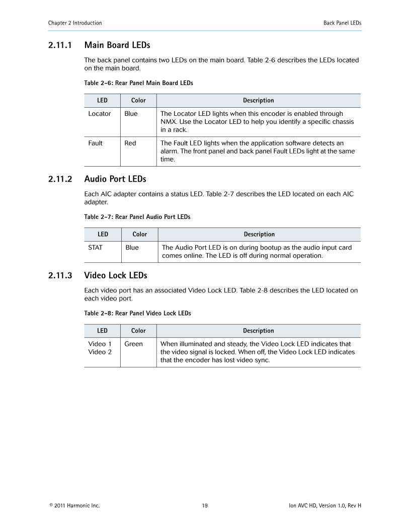
Chapter 2 Introduction Back Panel LEDs
copy 2011 Harmonic Inc 19 Ion AVC HD Version 10 Rev H
2111 Main Board LEDsThe back panel contains two LEDs on the main board Table 2-6 describes the LEDs located on the main board
Table 2-6 Rear Panel Main Board LEDs
LED Color Description
Locator Blue The Locator LED lights when this encoder is enabled through NMX Use the Locator LED to help you identify a specific chassis in a rack
Fault Red The Fault LED lights when the application software detects an alarm The front panel and back panel Fault LEDs light at the same time
2112 Audio Port LEDs Each AIC adapter contains a status LED Table 2-7 describes the LED located on each AIC adapter
Table 2-7 Rear Panel Audio Port LEDs
LED Color Description
STAT Blue The Audio Port LED is on during bootup as the audio input card comes online The LED is off during normal operation
2113 Video Lock LEDs Each video port has an associated Video Lock LED Table 2-8 describes the LED located on each video port
Table 2-8 Rear Panel Video Lock LEDs
LED Color Description
Video 1Video 2
Green When illuminated and steady the Video Lock LED indicates that the video signal is locked When off the Video Lock LED indicates that the encoder has lost video sync
copy 2011 Harmonic Inc 20 Ion AVC HD Version 10 Rev H
Chapter 3Installation
This chapter provides detailed instructions for installing a DiviCom Ion AVC HD encoder in a standard 19-inch rack and connecting cables
The chapter describes
How to prepare and unpack the Ion AVC HD
How to install the encoder in a rack
How to update the encoder software
How to connect the cables
31 PreparationYou need a Phillips screwdriver to mount the encoder in a standard 19-inch rack Harmonic ships the necessary rack-mount screws and rack rails
32 Unpacking The encoder comes in a specially designed shipping container that ensures the integrity of your encoder hardware during shipping and handling To avoid damage to the component follow the unpacking instructions that come with the encoder
When you unpack the encoder you should find the following items
Encoder
Standard IEC power cord
Spare air filters
Software warranty agreement
Harmonic ships rack-mounting kits in a separate shipping container
33 Installing the Encoder in a Rack You can install the encoder in different sizes and types of racks For rack assembly instructions consult the manual that came with the rack or the customer service department of the rack manufacturer
This section describes how to mount the encoder in a standard 19-inch rack using the two side-mount rails included in the rack-mounting kit A 30-inch-deep rack with a spacer or chimney between racks with multiple encoders is the recommended rack setup However these rails work for racks that are 30 to 36 inches deep
When you view the rack from the rear the power rail should be installed on the left side
Chapter 3 Installation Installing the Encoder in a Rack
copy 2011 Harmonic Inc 21 Ion AVC HD Version 10 Rev H
331 Rack GuidelinesWhen operating the encoder in the rack ensure that
The ambient temperature around the unit (which may be higher than room temperature) is within the limit specified for the unit
There is sufficient airflow around the unit
Electrical circuits are not overloaded consider the nameplate rating of all the connected equipment
There is overcurrent protection
The equipment is properly grounded
No objects are placed on top of the unit
332 Chassis Warnings for Rack Mounting and Servicing
CAUTION To prevent bodily injury when mounting or servicing this unit in a rack you must take special precautions to ensure that the system remains stable The following guidelines are provided to ensure your safety
This unit should be mounted at the bottom of the rack if it is the only unit in the rack
If the rack will hold a number of units load the rack from the bottom to the top with the heaviest component at the bottom of the rack
If the rack is provided with stabilizing devices install the stabilizers before mounting or servicing the unit in the rack
ATTENTION Pour eacuteviter toute blessure corporelle pendant les opeacuterations de montage ou de reacuteparation de cette uniteacute en casier il convient de prendre des preacutecautions speacuteciales afin de maintenir la stabiliteacute du systegraveme Les directives ci-dessous sont destineacutees agrave assurer la protection du personnel
Si cette uniteacute constitue la seule uniteacute monteacutee en casier elle doit ecirctre placeacutee dans le bas
Si cette uniteacute est monteacutee dans un casier partiellement rempli charger le casier de bas en haut en placcedilant lrsquoeacuteleacutement le plus lourd dans le bas
Si le casier est eacutequipeacute de dispositifs stabilisateurs installer les stabilisateurs avant de monter ou de reacuteparer luniteacute en casier
WARNUNG Zur Vermeidung von Koumlrperverletzung beim Anbringen oder Warten dieser Einheit in einem Gestell muumlssen sie besondere Vorkehrungen treffen um sicherzustellen daszlig das System stabil bleibt Die folgenden Richtlinien sollen zur Gewaumlhrleistung Ihrer Sicherheit dienen
Wenn diese Einheit die einzige im Gestell ist sollte sie unten im Gestell angebracht werden
Bei Anbringung dieser Einheit in einem zum Teil gefuumlllten Gestell ist das Gestell von unten nach oben zu laden wobei das schwerste Bauteil unten im Gestell anzubringen ist
Wird das Gestell mit Stabilisierungszubehoumlr geliefert sind zuerst die Stabilisatoren zu installieren bevor sie die Einheit im Gestell anbringen oder sie warten
333 Airflow The airflow through the encoder is critical for maintaining the proper temperature range Fans in the chassis draw air in through the front bezel and through the encoder The airflow ventilates out the right side (front view)
Chapter 3 Installation Installing the Encoder in a Rack
copy 2011 Harmonic Inc 22 Ion AVC HD Version 10 Rev H
CAUTION Do not obstruct the airflow of the encoder Severe equipment damage can result when the encoder cannot properly exhaust the airflow
334 Attaching the Rack Rails Attach the side-mount rack rails to the rack to hold the encoder in place Figure 3-1 illustrates the parts of the rack rails
Figure 3-1 Rack rails
To attach the rack rails to the rack
1 If needed place a Tinnermantrade speed nut with the nut on the outside of the rack over the holes to which you would like to mount the rails
NOTE Each of the four rack posts requires two speed nuts
2 Position the rack rails so the shelves are toward the inside of the rack
3 Using the 10 screws provided with the encoder screw the mounts into the speed nuts from the inside of the rack using the rack-mount holes that line up with the holes on the rack posts
Figure 3-2 illustrates attaching the rails
Figure 3-2 Attaching the rails to the rack
Chapter 3 Installation Installing Encoder Software
copy 2011 Harmonic Inc 23 Ion AVC HD Version 10 Rev H
CAUTION Make sure to install the rack rails with the shelf at the top of the rail If you install the rail upside down the rail blocks the encoder air vents which can result in overheating the encoder
335 Mounting the EncoderTo mount the encoder in a rack
1 Using both hands grasp the outside corners of the plastic front bezel and slowly pull to detach it from the encoder and expose the mount holes See Figure 3-3
2 Gently slide the encoder to rest on the rack rails
3 Push the encoder back until the rack-mount holes in the front of the encoder line up with the rack posts
4 Insert four screws through the mount holes in the front of the encoder through to the corresponding holes on the rack posts
5 Tighten the screws with a screwdriver
6 Carefully replace the front bezel of the encoder making sure you do not damage the air filters
Rack-mount Holes
Front Bezel
Figure 3-3 Mounting the encoder
34 Installing Encoder SoftwareYour encoder comes from the factory with the latest released software version installed Harmonic periodically releases software updates You can download new software to the encoder using NMX See the NMX online help for instructions for how to download and begin running new encoder software
Chapter 3 Installation Cabling the Encoder
copy 2011 Harmonic Inc 24 Ion AVC HD Version 10 Rev H
35 Cabling the Encoder CAUTION Do not make any cable connections when the power cord is connected You must unplug the power cable to turn off the encoder
The next sections describe how to connect the following cables
Video input
IP output
Ethernet management
Power
351 Back PanelFigure 3-4 shows a sample back panel of the DiviCom Ion AVC HD encoder configured with optional ASI and FLEX modules
AC Power
Fuse Cover
ASI module
Fault andLocator LEDs
FaultRelayPort
EthernetManagement Port
EthernetOutput Ports
PlugVideo Input Ports
(optional)FLEX module(optional)
Figure 3-4 Back panel
352 Connecting the Audio Input Cables An encoder may have up to five audio input cards (AICs) each of which has two stereo digital audio ports or up to five audio adapters (AHC AHC-RAC or AHC-561) each of which has four stereo digital audio ports When the encoder is equipped with an AHC-RAC used to support native AES input only three of the four digital audio ports on a card can be used at one time
To connect the audio cables
Connect a coaxial cable with a BNC connector from the digital audio port to the audio source On each AIC the digital audio ports are labeled DGTL AUD1 and DGTL AUD2 On each AHC the digital audio ports are labeled DGTL AUD1 DGTL AUD2 DGTL AUD3 and DGTL AUD4 For multichannel audio use three cables to connect the surround mix connecting LR to DGTL AUD1 CLfe to DGTL AUD2 and LsRs to DGTL AUD3 which maps the channels to AES3 pairs as defined by SMPTE 320M If the encoder is equipped with an AHC-RAC then one more stereo pair can be connected to DGTL AUD4 Otherwise the fourth connector is not used
Chapter 3 Installation Cabling the Encoder
copy 2011 Harmonic Inc 25 Ion AVC HD Version 10 Rev H
353 Connecting the Video Input Cables Your encoder has up to four video input ports The video input ports accept serial digital video To connect the video cables
1 Connect a coaxial cable with a BNC connector from the first video source to the Video 1 port on the encoder
2 Continue connecting the additional video sources to the remaining video ports
354 Connecting the IP Output Cables The encoder has one IP output port with two redundant channels and two RJ-45 connectors
NOTE The network hosting the IP output traffic must be a different network from your management network and must be configured with a different IP address
NOTE Harmonic recommends that shielded and grounded Ethernet cables be used on all Ethernet ports
To connect the IP output cables
1 Connect an Ethernet cable from the primary IP output port to a port on a network switch or router not a hub
2 Optionally connect the backup IP output port to a different switch or router to facilitate redundancy
3 Configure the Ethernet switch to support autonegotiation by setting each port to ldquoset speed autordquo and ldquoset duplex autordquo
NOTE Failure to properly configure the Ethernet switch could result in a mismatch between the IP output and the switch
Harmonic supports 101001000 Base-T and is fully compliant with IEEE 8023 8023u and 8023as standards
355 Connecting the Ethernet Management Cable The Ethernet management port allows communication between NMX and the encoder
To connect the Ethernet management cable
Connect an RJ-45UTP cable from the encoderrsquos back panel 10100 Base-T port to a port on an Ethernet switch
NOTE The network hosting the IP output traffic should be a different network from your management network
356 Connecting the AC Power The encoder AC power supply uses autosensing to adjust to different incoming voltages
CAUTION This product relies on the buildingrsquos electrical installation for short-circuit (overcurrent) protection Ensure that a fuse or circuit breaker no larger than 120 VAC 20 A US (240 VAC 20 A international) is used on the phase conductors (all current-carrying conductors)
Chapter 3 Installation Cabling the Encoder
copy 2011 Harmonic Inc 26 Ion AVC HD Version 10 Rev H
ATTENTION Pour ce qui est de la protection contre les courts-circuits (surtension) ce produit deacutepend de lrsquoinstallation eacutelectrique du local Veacuterifier qursquoun fusible ou qursquoun disjoncteur de 120 V alt 20 A US maximum (240 V alt 20 A international) est utiliseacute sur les conducteurs de phase (conducteurs de charge)
WARNUNG Dieses Produkt ist darauf angewiesen daszlig im Gebaumlude ein Kurzschluszlig-bzw Uumlberstromschutz installiert ist Stellen sie sicher daszlig eine Sicherung oder ein Unterbrecher von nicht mehr als 240 V Wechselstrom 20 A (bzw in den USA 120 V Wechselstrom 20 A) an den Phasenleitern (allen stromfuumlhrenden Leitern) verwendet wird
To connect the power cord
Connect the power cord to the power plug on the encoder back panel and connect the power cord to the power outlet
CAUTION The power supply cord is used as the main disconnect device Ensure that the socketoutlet is locatedinstalled near the equipment and is easily accessible
ATTENTION Le cordon drsquoalimentation est utiliseacute comme interrupteur geacuteneacuteral La prise de courant doit ecirctre situeacutee ou installeacutee agrave proximiteacute du mateacuteriel et ecirctre facile drsquoacceacutes
WARNUNG Das Netzkabel dient als Netzschalter Stellen sie sicher das die Steckdose einfach zugaumlnglich ist
Power Supply Cord Notice
CAUTION This unit has more than one power supply connectionrsquo all connections must be removed to remove all power from this unit
ATTENTION Cette uniteacute est eacutequipeacutee de plusieurs raccordements dalimentation Pour supprimer tout courant eacutelectrique de luniteacute tous les cordons dalimentation doivent ecirctre deacutebrancheacutes
WARNUNG Diese Einheit verfuumlgt uumlber mehr als einen Stromanschluszlig um Strom gaumlnzlich von der Einheit fernzuhalten muumlssen alle Stromzufuhren abgetrennt sein
Laser warning
Warning Class 1 laser product
Attention Produit laser de classe 1
Warnung Laserprodukt der Klasse 1
copy 2011 Harmonic Inc 27 Ion AVC HD Version 10 Rev H
Chapter 4Operating the Encoder
After installing the encoder in a rack and connecting the cables as described in Chapter 3 Installation configure the encoder platform and services
The chapter describes
How to use NMX Digital Service Manager to configure the Ion AVC HD
How to use the Ion AVC HD front panel
41 Operating with NMX Digital Service ManagerWhen you use NMX Digital Service Manager to manage the encoders in your network you perform all encoder configuration including IP address assignment in NMX You do not need to do any configuration from the encoder front panel
See the NMX online help for instructions for adding an encoder to an NMX network group You will need to know the encoder MAC address when you add the encoder to a network group See 424 Viewing the Encoder MAC Address on page 29 for instructions for viewing the MAC address in the front panel display
42 Using the Front Panel You can perform some initial network configuration from the encoder front panel From the front panel you can set the encoderrsquos IP address default gateway and subnet mask and you can view the encoderrsquos MAC address and serial number
421 The Keypad The keypad on the local control panel provides the following functions
Access to the menus
Navigation through the menu hierarchies to their parameters
Editing capabilities
Figure 4-1 shows the keypad
Hot Keys Navigation andFunction Keys
Alphanumeric Keys
Figure 4-1 Front panel keypad
Seven hot keys provide immediate access to the encoder menus The Network and Help hot keys are currently active The other hot keys are reserved for future use
Chapter 4 Operating the Encoder Using the Front Panel
copy 2011 Harmonic Inc 28 Ion AVC HD Version 10 Rev H
Navigation and function keys located to the right of the hot keys provide a tool for navigating through the menu hierarchies and changing parameter values Use the alphanumeric keys to enter new values
422 Front Panel Display
The two-line 20-character vacuum fluorescent display (VFD) shows the menus parameters and options As illustrated in Figure 4-2 line 1 of the local control panel display shows the menu path for the currently selected option To represent a path the VFD displays each submenu as two or more letters and a colon
Line 2 of the display shows the second line of a help message or a parameter value To change this value you must enter the new value using the keypad
NTWK Control IPParameter Requires
Value to be Edited
Value Setting
19216824101
Figure 4-2 Setting a value in the front panel display
A blinking cursor shows the current value A steady cursor shows the value being edited
Press the Help key to display an online message for the currently selected menu item
423 Setting the Encoder Network PropertiesBefore you can begin to configure the encoder you must set the encoder IP address subnet mask and default gateway The encoder ships with a default IP address based on the encoder serial number The default subnet mask is 255000 and the default gateway address is 10001
4231 Setting the IP Address
To set the encoder management port IP address
1 Press the NTWK hot key
The VFD display shows NTWK Configuration
2 Press the
v key to navigate to NTWK Control IP
3 Press Enter
4 Enter the IP address using the alphanumeric keys
TIP To enter a period press the Shift key and the 0 key
5 When you finish press Enter
Do not exit the Network menu because you can set the other properties from here
Chapter 4 Operating the Encoder Using the Front Panel
copy 2011 Harmonic Inc 29 Ion AVC HD Version 10 Rev H
4232 Setting the Subnet Mask
To set the subnet mask
1 Press the
v key to navigate to NTWK Control Subnet
2 Press Enter
3 Enter the subnet mask using the alphanumeric keys
TIP To enter a period press the Shift key and press the 0 key
4 When you finish press Enter
4233 Setting the Default Gateway Address
To set the gateway address
1 Press the
v
key to navigate to NTWK Gateway
2 Press Enter
3 Enter the default gateway using the alphanumeric keys
TIP To enter a period press the Shift key and press the 0 key
4 When you finish press Enter
5 Press Esc to exit the Network menu
424 Viewing the Encoder MAC Address You can view the encoder MAC address from the front panel
To view the encoder MAC address
1 Press the NTWK hot key
2 Press the
v
key several times to navigate to NTWK Control MAC
The MAC address appears beneath the parameter name
3 Press Esc to exit the parameter
425 Viewing the Encoder Serial NumberYou can view the encoder serial number from the front panel
To view the encoder serial number
1 Press the STAT hot key
2 Press the
v
key to navigate to STAT Serial Number
The serial number appears beneath the parameter name
3 Press Esc to exit the parameter
Chapter 4 Operating the Encoder Licensing Information
copy 2011 Harmonic Inc 30 Ion AVC HD Version 10 Rev H
43 Licensing InformationLicensing is required for some encoding features and you cannot enable those features without the appropriate licensing You can add licenses to your system at any time using the SAG (Web GUI) You must acquire licenses from Harmonic When licenses expire streams will continue to flow as configured but cannot be modified or re-enabled if disabled for any reason Streams that include features under license will raise alarms when their licensing expires Alarms will also be raised to advise you that licensing is required for a given feature if that feature is blocked Also any attempted changes after a license expires may be service affecting and other operations such as redundancy may not operate properly For additional information on using the Configuration Manager for licensing operations refer to your encoderrsquos online help
Under the Licensing tab (on Platform Configuration page) you can
Apply license keys that have been created and sent to you by Harmonic in a lic license file The license file is unique to a specific encoder and can be used on that encoder only once When you apply a license the system scans the encoder platform for the matching devicefeature and binds the license key to that encoder One lic file may contain multiple license keys Every key in the lic file will be applied One license key may unlock multiple instances of a feature There is no undo for applying licenses but you can delete them
Delete a license key and save the deletion receipt for return to Harmonic If you want to remove a license key from one device to use it on another you must delete it When you delete a key the device releases it and a unique deletion receipt is created This receipt must be sent to Harmonic so that the deleted license can be made available in the license database for use in a different encoder There is no undo for deletion You must provide the deletion receipt to Harmonic to make the license available for use again
View the current licenses that are on the encoder platform
To apply licenses
If you ordered a new license you received a file To install it on this encoder follow these steps
1 Click the Add license button The license Loader window opens
2 Type in the path and file name where you saved the new license file or use the Browse button and navigate to it
3 Click the Transfer button The encoder applies all the license keys that are in the lic file and binds them to the encoder The new licenses appear in the license table
4 Disable then re-enable the affected streams if applicable
To delete licenses
Contact Harmonic customer support for more information
copy 2011 Harmonic Inc 31 Ion AVC HD Version 10 Rev H
Chapter 5Maintenance and Troubleshooting
This chapter describes
How to maintain and replace the air filters and fuse
How to contact Harmonic Support
51 Air Filters The encoder uses two air filters to minimize dust and dirt in the circuitry and components in the chassis These filters are made of flexible compressed fiber spun from urethane foam Installed in the front of the encoder the filters are fire retardant and conform to UL 900 Class II specifications
The bezel filter is located inside the front bezel on the left side Figure 5-1 shows the dimensions of the bezel filter The notches on the left side and the cutouts in the middle can fit on either side of the front bezel mounting posts
532 inches
164 025 inchesinches
Figure 5-1 Bezel filter (front view)
The keypad filter is located behind the front panel keypad Figure 5-2 shows the keypad filter
645 inches
025 inches
164inches
Figure 5-2 Keypad filter (front view)
511 Maintaining the Air Filters The operating environment of the encoder plays a large factor in determining the life of the air filters Encoders that operate in dusty and dirty surroundings require more frequent inspections and filter cleaning than those operating in cleaner environments
Inspect and clean the filters with a frequency that is appropriate to the environment in which the encoder operates Harmonic recommends inspecting and cleaning the filters every six weeks to ensure proper airflow through the chassis
To clean dust and dirt from the filters you can use a vacuum cleaner to remove the dirt or you can rinse the filters in water You can also use soaps or mild detergents on the filters If you rinse the filters in water make sure that you squeeze the excess water from them before reinstalling them in the encoder You might need to order replacement filters if the filters become too dirty over time
Chapter 5 Maintenance and Troubleshooting Fuse
copy 2011 Harmonic Inc 32 Ion AVC HD Version 10 Rev H
512 Removing and Replacing the Air Filters You do not need to turn off the encoder when removing and replacing the air filters
5121 Removing and Replacing the Bezel Filter
To remove the front left filter from behind the front bezel
1 Grasp each side of the encoderrsquos front bezel with your hands
2 Carefully remove the front bezel by pulling it away from the encoder
3 Remove the filter from inside the front bezel
4 Inspect the air filter for dirt and clean it if necessary
NOTE When the filter is new its color is medium charcoal As dust and dirt collect in the porous filter material the filterrsquos color gradually changes to brown then an ash color
5 Replace the filter inside the front bezel Place the filter so that the long horizontal slot is at the bottom edge Carefully place the cutouts in the filter around the bezel mounting posts
6 Carefully replace the front bezel on the encoder making sure the filter does not fall out of the bezel
5122 Removing and Replacing the Keypad Filter
To remove the air filter from behind the keypad
1 Grasp each side of the encoder front bezel with your hands
2 Carefully remove the front bezel by pulling it away from the encoder
Note the location of the filter The keypad is screwed onto the front of the encoder through four mounting posts Cutouts on the filter wrap around the four posts and the right side of the filter extends past the keyboard
3 Remove the filter by pulling the left side of the filter up and away from the keyboard mounting posts then pulling up the right side
4 Inspect the air filter for dirt and clean it if necessary
5 Replace the filter by inserting the right side of the filter behind the keypad with the vertical slots around the mounting posts
6 Insert the left side of the filter placing the horizontal cutouts around the mounting posts
7 Carefully replace the front bezel on the encoder making sure the filter does not fall out of the bezel
52 Fuse Encoders use a slow blow 40 A 250 V fuse 5 x 20 mm The fuse is located on the back panel beside the power input A spare fuse is located in the fuse cover shown in Figure 5-3
Fuse cover
Figure 5-3 Fuse cover and AC power input
Chapter 5 Maintenance and Troubleshooting Contacting Harmonic Support
copy 2011 Harmonic Inc 33 Ion AVC HD Version 10 Rev H
521 Replacing the FuseTo replace the fuse
1 Unplug the power cord from the chassis
DANGER You must disconnect the power cord before removing the fuse
2 Pull down the fuse cover on the back panel
3 Remove the old fuse
4 Install the new fuse
DANGER Always replace the fuse with a fuse of the same rating and type Using a different fuse voids the Harmonic warranty and could result in fire or other electrical damage
5 Replace the fuse cover
6 Plug in the encoder
53 Contacting Harmonic SupportThe Harmonic Customer and Technical Support groups are available to help you with any questions or problems you may have regarding Harmonic products
For assistance from within the US and Canada call toll free
1888MPEGTWO (6734896)
For assistance from outside the US and Canada call
14084906477
The fax number is 4084906770
The email address is techhelpharmonicinccom
The corporate address for Harmonic Inc is
Harmonic Inc 549 Baltic Way Sunnyvale CA 94089 USA Attn Customer Support
The corporate telephone numbers for Harmonic Inc are
Tel 18007881330 (from the US and Canada) Tel +14085422500 (outside the US and Canada) Fax+14084906708
The web address for Harmonic Inc is wwwharmonicinccom
copy 2011 Harmonic Inc 34 Ion AVC HD Version 10 Rev H
Appendix AEncoder Specifications
This appendix contains a comprehensive list of the environment and physical characteristics of the encoder electrical specifications and information about the pinouts for the input and output ports
A1 Environment Specifications Table A-1 lists environment specifications for the encoder
Table A-1 Environment Specifications
Parameter Specification
Size 445 cm x 4826 cm x 6069 cm (175 in x 19 in x 24 in)
Weight 11 kg (24 lb)
AC Power
AC 100-240V (auto ranging)
47 to 63 Hz
1 channel (ELC-7011) 108 W 2 channel (ELC-7022) 162 W 3 channel (ELC-7033) 216 W 4 channel (ELC-7044) 270 W
63A 250V fuse 5 x20mm
Temperature
5 to 40 degC (41 to 104 degF)
ndash20 to +80 degC (ndash4 to +176 degF)
Humidity
lt 95 noncondensing
lt 95 noncondensing
Altitude
lt 15000 feet (4572 meters)
lt 40000 feet (12192 meters)
Shock and Vibration
Passes the impact compression and vibration requirements of ASTM D4169-94 Distribution Cycle 13 Assurance Level 1
Passes NEBS Office Vibration Test while operating (01G sine sweep 5 to 100 Hz 3 axis)
Input voltage range
Line frequency
Typical consumption
Fuse
Operating
Storage
Operating
Storage
Operating
Storage
Packaged
Operating
Appendix A Encoder Specifications Port Specifications
copy 2011 Harmonic Inc 35 Ion AVC HD Version 10 Rev H
A2 Port Specifications Table A-2 lists the specifications for the back panel port connections For port locations see the illustration of the back panel on Figure 3-4 on page 24
Table A-2 Port Specifications
Port Connection Specification
Video input port
Serial DigitalSignal format per SMPTE 292M
75 Ω unbalanced
BNC
Ethernet management port
10100 Base-T
8023
RJ-45
Input serial port Reserved for future use
Ethernet output port
101001000 Base-T
MPEG-4 over IP
RJ-45
Fault relay port Capable of switching 025 amps at 30 VDC
Phoenix 1881383
A3 Port Pinouts The following sections describe the Ethernet management and fault relay port pinouts
A31 Ethernet Management Port The Ethernet management port is 10100 Base-T and uses an RJ-45UTP port to connect to an Ethernet network Use this port to manage the encoder with NMX See 355 Connecting the Ethernet Management Cable on page 25 for cabling instructions
Table A-3 lists the pinouts for the RJ-45 Ethernet port
Protocol
Impedance
Connector type
Type
Protocol
Connector type
Type
Protocol
Connector type
Mating connector type
Table A-3 Ethernet Management Port Pinout
Pin Signal
1 Transmit data (TD) +
2 Transmit data (TD) ndash
Appendix A Encoder Specifications Port Pinouts
copy 2011 Harmonic Inc 36 Ion AVC HD Version 10 Rev H
A32 Fault RelayGPI Ports A contact closure is a physical connection between two platforms that define the state of the platform by being either on or off
Both NMX and SAG provide alarm management and redundancy for third party devices through contact closure monitoring Additionaly the contact closure on the Electra and Ion-based encoders can also be used as DPI inputs to the encoder A contact closure is a physical connection (Figure A-1) between two platforms that define the state of the platform by being either on or off Table A-4 lists the fault relay pinouts Individual wires need to be inserted into the contacts and grounded to the ground pin to activate a contact closure When configured in the DPI properties page (of either NMX or the SAG) an SCTE35 message is sent out when that pin is set to low Each is independent and can be provisioned to any one channel and multiple available channels
The fault relay port connects to a Form C relay that can switch up to 025 A at 30 VDC
Table A-4 Fault RelayGPI Port Pinout
Pin Connection
1 Normally closed (NC)
2 Normally open (NO)
3 Common (CM)
4 GPI contact 1
5 GPI contact 2
6 GPI contact 3
7 GPI contact 4
8 Ground (GND)
3 Receive data (RD) +
4 Not connected
5 Not connected
6 Receive data (RD) ndash
7 Not connected
8 Not connected
Table A-3 Ethernet Management Port Pinoutcontinued
Pin Signal
Appendix A Encoder Specifications Port Pinouts
copy 2011 Harmonic Inc 37 Ion AVC HD Version 10 Rev H
Figure A-1 Fault RelayGPI Ports
copy 2011 Harmonic Inc 38 Ion AVC HD Version 10 Rev H
Appendix BAudio and Video Specifications
B1 AIC FeaturesThe AIC adapter accepts analog (balanced or unbalanced) discrete AES3SPDIF digital and AES3 embedded in serial digital video inputs For analog and discrete AES3 inputs sampling frequencies of 48 kHz 441 kHz and 32 kHz are supported Embedded digital is supported only for 48 kHz sampling which must be synchronous to the video
Table B-1 lists the AIC features for each coding mode including the supported sampling frequencies and ES bit rates
Table B-1 AIC Features
AIC Feature Coding Mode SamplingFrequency
ES Bit RatesSupported (Kbps)
MPEG-1 Layer II compression
Single channel (10) 32 kHz 441 kHz 48 kHz
32 48 56 64 80 96 112 128 160 192
Dual channel (1+1) Stereo channel (20) Joint stereo channel
32 kHz 441 kHz 48 kHz
64 96 112 128 160 192 224 256 320 384
MPEG-1 Layer II compression SPPC (separate PID per channel)
Single channel (10) 32 kHz 441 kHz 48 kHz
32 48 56 64 80 96 112 128 160 192
Dolby Digital (AC-3) compression
Single channel (10) 32 kHz 441 kHz 48 kHz
56 64 80 96 112 128 160 192 224 256 320
384 448a 512a 576a
640a
Stereo channel (20) 32 kHz 441 kHz 48 kHz
96 112 128 160 192
224 256 320 384 448a
512a 576a 640a
Dolby Digital (AC-3) passthrough
Up to 51 channels (32+LFE professional 16-bit mode)
32 kHz441 kHz48 kHz
56b 80b 96 112 128 160 192 224 256 320 384
448a 512a 576a 640a
Up to 51 channels (32+LFE professional 32-bit mode)
32 kHz441 kHz48 kHz
256 320 384 448a 512a
576a 640a
Appendix B Audio and Video Specifications AIC Features
copy 2011 Harmonic Inc 39 Ion AVC HD Version 10 Rev H
Note the following limitations
ATSC Standard A53 specifies that only 48 kHz sampling may be used and that ES bit rates must be less than or equal to 384 Kbps for a complete service It also specifies that a two-channel dialog-only service must be less than or equal to 192 Kbps Total ES rates for all services must be less than or equal to 512 Kbps
Embedded audio must be 48 kHz sampling and synchronous with the video See SMPTE 272M for definitions
MPEG AAC and HE AAC can be placed into the output Transport Stream encapsulated in either of two methods
ADTS
ADTS is an acronym for ldquoAudio Data Transport Streamrdquo This is the default used if the user selects MPEG-2 AACHE AAC ADTS is assigned a stream type value of 0x0F
LATMLOAS
LATM is an acronym for rdquoLow Overhead Audio Transport Multiplexrdquo LOAS is an acronym for rdquoLow Overhead Audio Streamrdquo and furnishes an outer wrapper for LATMs inner wrapper of the raw audio Elementary Stream syntax MPEG-4 AAC and HE AAC bitstreams are encapsulated as LATMLOAS and assigned a stream type value of 0x11
Encapsulation mode is controlled by selecting rdquoMPEG-2rdquo or rdquoMPEG-4rdquo as required
MPEG HE AAC compression
Single channel (10) 32 kHz441 kHz48 kHz
32 48 56 64 96
Dual channel (1+1) Stereo channel (20) Joint stereo channel
32 kHz441 kHz48 kHz
32 48 56 64 96 112 128
MPEG AAC compression
Single channel (10) 32 kHz441 kHz48 kHz
32 48 56 64 96 112 128 182 192
Dual channel (1+1) Stereo channel (20) Joint stereo channel
32 kHz441 kHz48 kHz
64 96 112 128 182 192 224 256 320 384
a These rates are not compliant with A53b These rates are valid for 10 coding only
Table B-1 AIC Features continued
AIC Feature Coding Mode SamplingFrequency
ES Bit RatesSupported (Kbps)
Appendix B Audio and Video Specifications Dolby Digital (AC-3) Audio
copy 2011 Harmonic Inc 40 Ion AVC HD Version 10 Rev H
B2 Dolby Digital (AC-3) Audio The Ion AVC HD supports Dolby Digital (AC-3) native audio encoding AIC-equipped encoders support native two-channel Dolby Digital (AC-3) compression AIC-equipped encoders also support Dolby Digital (AC-3) 51 in passthrough mode
NOTE Harmonic supports Dolby Digital (AC-3) passthrough rates of 96 to 640 Kbps and native Dolby Digital (AC-3) rates of 56 to 640 Kbps
Table B-2 lists the bit rates for the sample frequencies of 48 kHz 441 kHz and 32 kHz
Table B-2 Dolby Digital (AC-3) Audio Bit Rates
Audio Bit Rate (Kbps)
Audio without PCR Audio with PCR
48 kHz 441 kHz 32 kHz 48 kHz 441 kHz 32 kHz
56 658 605 627 658 605 627
64 752 691 689 752 691 689
80 846 864 877 846 864 877
96 1034 1036 1003 1034 1036 1065
112 1222 1209 1191 1222 1209 1191
128 1316 1382 1316 1410 1382 1379
160 1692 1641 1692 1692 1727 1692
192 1974 1986 2005 2068 1986 2005
224 2350 2332 2319 2350 2332 2319
256 2632 2677 2632 2726 2677 2695
320 3290 3282 3321 3384 3368 3321
384 3948 3973 3948 4042 3973 3948
448 4606 4664 4637 4606 4664 4637
512 5264 5268 5264 5264 5268 5264
576 5922 5959 5891 5922 5959 5953
640 6580 6564 6580 6580 6564 6580
NOTE Changing from non-single-channel mode to single-channel mode provisions the transport bit rate automatically
When you change between single-channel and non-single-channel modes the encoder automatically provisions the bit rate to the closest available bit rate In some cases this means the bit rate is lower because provisioning does not increase the bit rate defined for the port Therefore changing the coding mode from non-single-channel mode to any of the four highest bit rates causes the encoder to provision the bit rate to 192 Kbps
Appendix B Audio and Video Specifications Video Specifications
copy 2011 Harmonic Inc 41 Ion AVC HD Version 10 Rev H
In the case of the three lowest bit rates when you change from single-channel to non-single-channel mode because the bit rate is the lowest available the encoder provisions to the next highest available bit rate 64 Kbps If you set the bit rate to 80 Kbps and then change the coding mode to non-single-channel the encoder provisions the bit rate to 64 Kbps
B3 Video Specifications The encoder is equipped to handle high definition (HD) serial digital input (SDI)
Table 5-1 Video Specifications
Feature Specification Comments
Input formats Serial digital component High definition serial digital interface (HD-SDI) per SMPTE 292M
VITC support 1080i 30MB 720p 60MB
Import formats supported in HD
B4 VITC SupportThe Ion AVC HD supports extraction of Vertical Interval Time Code (VITC) data placed into VANC or HANC per SMPTE RP188 The VITC data is used to synchonize DPI events on hoth HD and SD encoders HD encoders receive VITC input carried in the Vertical Ancillary data space (VANC) or Horizontal Ancillary data space (HANC) of a 292MB stream
copy 2011 Harmonic Inc 42 Ion AVC HD Version 10 Rev H
Appendix CEncoder Back Panel Slot Locations
C1 Adapter Configurations for All EncodersFigure C-1 represents the back panel of an encoder Table C-1 shows the slot number and the modules that can be installed in encoders that are not associated with a FLEX module Table C-2 shows the slot number and the modules associated with the FLEX module that can be installed NMX uses the slot number to differentiate between adapters of the same type within the encoder
Slot 2
Slot 1 Slot 3
Slot 4 FLEX
Main Board
Slot 5 FLEX
Figure C-1 Slot numbers
Table C-1 shows the adaptersmodules software support and configuration recommendations for non-FLEX based encoders
Table C-1 Supported adaptersmodules and configuration recommendations for this encoder
Adapter Slot Notes
AIC Any slot (1-5 adapters per chassis)
AHC-RAC Any slot (1-5 adapters per chassis)
AHC-561 Slots 1- 4 (1-4 adapters per chassis) Not supported on slot 5 Supported only via NMX
ASI Output Slot 5 without a FLEX module Slot 2 with a FLEX module (1 adapter per chassis)
Only the first two ports are active and are electrical duplicates of each other
AB Power Input switch
Slots 1 and 3 (both)
C11 Additional Adapter Configurations for FLEX-based EncodersTable C-2 lists the adapter configurations available for FLEX-based encoders
Table C-2 FLEX Module Options (for use with FLEX module)
Card Option Notes
FLEX Slot 4 must be populated first slot 5 second (1-2 adapters per chassis)
Requires CPC revision 105 or higher see Viewing the Control Board (CPC) Revision Information on page 43
GbE Slot 1 only (1 adapter per chassis)
Used with FLEX module for input only
Appendix C Encoder Back Panel Slot Locations Adapter Configurations for All Encoders
copy 2011 Harmonic Inc 43 Ion AVC HD Version 10 Rev H
NOTE ASI Input adapters (used with FLEX module) and ASI Output adapters utilize the same hardware but perform different functions based on 1) the slot number and 2) if a FLEX module is installed If installed in slots 2 or 5 the ASI adapter is always an output If a FLEX module is installed an ASI adapter installed in slots 1 or 3 is an input
C12 Viewing the Control Board (CPC) Revision Information1 From the Platform tab click on the Platform link
2 Click on the Control Board (CPC) link
The Control Board (CPC) Configuration page appears
Click on the Maintenance tab to examine the version information
ASI Input Slot 1 (typical) slot 3 if slot 1 isalready in use (1 card perchassis) For FLEX only chassisthe FLEX module goes into slot4 and 5 Slot 4 must bepopulated first For baseband andcompressed mixed inputencoders the FLEX module canbe either slot 4 or 5 ASI inputadapters cannot use slot 4 as itis used for first FLEX module
ASI input is currently only forFLEX module ASI in slots 1 3and 4 appears as an input card
RF 8VSB Slot 1 (typical) or slot 3 if slot 1 is already in use or slot 2 if slots 1 and 3 are already in use (1 adapter per chassis)
Used with FLEX module for input only
Table C-2 FLEX Module Options (for use with FLEX module)
Card Option Notes
copy 2011 Harmonic Inc 44 Ion AVC HD Version 10 Rev H
Appendix DBoot Sequence
This appendix describes the encoder boot sequence including the messages that appear on the local control panel display
D1 Local Control Panel Display Messages during BootupMessages on the local control panel indicate progress during boot-up During a successful boot many events occur so quickly you cannot see the messages The following sections describe the messages that you can see during boot attempts
NOTE During the boot sequence do not press any key on the keypad
The following sequence describes the display on the vacuum fluorescent display (VFD) during a successful startup
Power on
VFD line 1 = Harmonic Inc VFD line 2 = System Loading
Begin loading
VFD line 1 = Divicom Ion AVC HD VFD line 2 = System Loading
Booting
VFD line 1 = Divicom Ion AVC HD VFD line 2 = Loading xxxxxxxxelf
Finished
VFD line 1 = Divicom Ion AVC HD VFD line 2 = Multichannel Encoder
D2 Other Local Control Panel Display MessagesThe local control panel displays messages for other types of restarts including a system reset and loading new software
D21 Resetting the Encoder When you reset the encoder from NMX a message on the VFD shows that the encoder has been reset The encoder uses the boot file on the hard drive when you reset it
Reset from NMX
VFD line 1 = Bye bye VFD line 2 =
After power cycle
VFD line 1 = Harmonic Inc VFD line 2 = System Loading
Begin loading
Appendix D Boot Sequence Other Local Control Panel Display Messages
copy 2011 Harmonic Inc 45 Ion AVC HD Version 10 Rev H
VFD line 1 = Divicom Ion AVC HD VFD line 2 = System Loading
Booting
VFD line 1 = Divicom Ion AVC HD VFD line 2 = Loading xxxxxxxxelf
Finished
VFD line 1 = Divicom Ion AVC HD VFD line 2 = Multichannel Encoder
D22 Loading New Software You can download new software to an encoder using NMX After downloading the software restart the encoder to begin using the new software The following messages appear
Begin loading
VFD line 1 = Divicom Ion AVC HD VFD line 2 = System Loading
Booting
VFD line 1 =Divicom Ion AVC HD VFD line 2 = Loading xxxxxxxxelf
Finished
VFD line 1 = Divicom Ion AVC HD VFD line 2 = Multichannel Encoder
copy 2011 Harmonic Inc 46 Ion AVC HD Version 10 Rev H
Appendix EWiring the ndash48 VDC Power Supply
If your encoder has the optional ndash48 VDC power supply follow these steps to wire the power supply
E1 Getting StartedBefore you begin wiring the ndash48 VDC power supply make sure that you provide the necessary overcurrent protection wires and power connector
E2 Power Source SpecificationsThe DC power source feeding the encoder must meet the following requirements
Electrically isolated from any AC power source
Positive ground The Positive bus of the DC power source must be reliably connected to the Ground bus
Each feed-pair must provide a continuous supply of power that meets the following specifications
Table E-1 Power Source Specifications
Parameter Specification
Voltage 40ndash60 VDC
Max operating current 8 amps
Max input surge current
20 amps
E3 Overcurrent ProtectionTo provide overcurrent protection
Provide overcurrent protection devices as part of each rack housing encoders
Locate a readily accessible disconnect device between the DC power source and the encoder
Use a 10-amp double-pole fast trip DC-rated disconnect device for each DC power connector
NOTE Overcurrent protection devices must meet applicable national and local electrical safety codes and be approved for the intended application
E4 Wiring RequirementsThe encoder is connected to the DC power source using three wires
ndashVin
GND
Appendix E Wiring the ndash48 VDC Power Supply Power Connector
copy 2011 Harmonic Inc 47 Ion AVC HD Version 10 Rev H
+Vin
Although Harmonic provides the power input connector with the encoder you must supply the wires
The wires to be used must comply with the following specifications
Table E-2 Recommended Wire Specifications
Parameter Specification
Suitable conductor material Copper only
ndashVin and +Vin wires 16 AWG rating
Ground cable 16 AWG rating
Cable insulation rating Minimum 80 C low smoke fume (LSF) flame retardant
Cable type Must comply with at least one of the following standards
Branch circuit cable insulation color
Per applicable national electrical codes
E5 Power ConnectorThe encoder is supplied with a special DC power connector plug that matches the DC power socket on the back of the encoder
This connector is made by WAGO model number 231-103037-000
Use only the original connector for connecting the encoder to the DC power source Contact Harmonic Technical Support if you want to use any other type of connector
The following figure shows the connector and its strain relief housing
Figure E-1 CableStrain Relief Housing
E6 Assembling the DC Input Power CableTo assemble the DC input power cable
1 Prepare the power wires as specified in E4 Wiring Requirements on page 46
2 Use the disconnect device to make sure that the power supply from the DC power source to the cables is switched off
UL 1581 (VW-1) - UL style 1028 or equivalent EEE 383 EEE 1202-1991
Appendix E Wiring the ndash48 VDC Power Supply Assembling the DC Input Power Cable
copy 2011 Harmonic Inc 48 Ion AVC HD Version 10 Rev H
CAUTION Turn off the power before proceeding with these instructions
3 Unplug the WAGO power connector from the power socket on the encoder back panel
4 Identify the three wires coming from the DC power source that are used in the connection to the expansion unit
ndashVin
+Vin
GND
5 Strip up to 03 inches (8 mm) of insulation from each of the wires coming from the DC power source
Do not strip more than this length from each wire Stripping more leaves uninsulated wire exposed outside the DC connector after the assembly is complete
6 Insert a small screwdriver into the rectangular hole directly above the hole in the DC connector where you want to insert the first cable and press down on the screwdriver
This opens the cage clamp for this section of the DC plug connector
NOTE WAGO also sells tools specifically designed to open cage clamps easily For more information either visit the WAGO web site at wwwwagocom or call WAGO at 1-800-346-7245 and request information about items 210-250 or 231-131
7 Feed the exposed section of the wire into the matching hole in the DC plug connector
See the pin-out figure below to match wires with the required holes
Figure E-2 Pin Out Specification
8 Repeat steps 5 through 7 for the other two wires to complete the assembly of the DC input cable
NOTE If you need to remove a wire from the DC plug connector insert a small screwdriver into the slot directly above the wire and press down on the screwdriver to free the wire from the cage clamp
copy 2011 Harmonic Inc 49 Ion AVC HD Version 10 Rev H
Appendix FDiviComtrade FLEX Decoding Module
F1 IntroductionThe DiviCom FLEX decoding module delivers video decoding capability and is integrated into either an Electra or Ion encoder chassis (which will be referred to as the ldquohostrdquo encoder) The FLEX decoding module (hereafter referred to as the FLEX module) is a decoding module only (see Figure F-1) A single FLEX module is able to decode up to two (2) incoming channels and an appropriately configured encoder can deliver up to four (4) channels in a single rack-unit (1-RU) The FLEX module decodes MPEG-2 in both standard definition (SD) or high definition (HD) formats thereby eliminating the dependency on ingress formats The FLEX module is a unique gateway designed with the flexibility to deliver any type of pre-compressed video to any host encoder The FLEX module supports both ASI and IP inputs the most efficient interfaces used to route and transport pre-compressed video feeds
NOTE AHC-561 card is not supported for use with FLEX modules
The FLEX module is controlled and configured with the NMX Digital Service Manager application or the Configuration Manager the Web-based GUI The FLEX module also accepts decoded ATSC 8VSB signals from the DiviCom RF Input Card ( DiviComtrade RF Input Adapter on page 74) The FLEX module does not descramble or reconstruct all audio and ancillary data services (such as VBI) on the output port
NOTE The encoder chassis configuration must include an input module for IP The same GbE Pro card are used for both ProStream 1000 muxes and Electra encoders
Figure F-1 FLEX Module Ports
F2 Video Decoding Specifications Table F-1 describes video specifications supported by the Table F-1describes video specifications supported by the FLEX module See the following tables for more information about video and audio compression See the following tables for more information about video and audio compression
Table F-1 Video Decoding Features
Feature Support
Video Decoding MPEG-2 MPML MPEG-2 MPHL
Aspect Ratios 43 and 169
Appendix F DiviComtrade FLEX Decoding Module Audio Passthrough Specifications
copy 2011 Harmonic Inc 50 Ion AVC HD Version 10 Rev H
F3 Audio Passthrough SpecificationsTable F-2 describes the audio passthrough specifications supported by the FLEX module
Table F-2 Audio Passthrough Specifications
Feature Support
Number of channels
Audio formats
Audio processing
Operating modes
Video Formats 480i2997 576i25 720p5994 72050 1080i25 1080i2997
Additional features (available on some specific hosts only)
General HD decode and downcovert to SDSD hosts only Decodes MPEG-2 MPML (480i and 576i)HD hosts only Decodes MPEG-2 MPHL (720p 5060 and 1080i
5060)Specific hosts only ASI input and output available with FLEX module (using
two ASI cards)
8 (however the total passthrough bitrate per FLEX program cannot exceed 4Mbps)
MPEG-1 Layer II Dolby Digital (AC-3) and AAC audio passthrough
MPEG-1 Layer II10 and 20 decode Dolby AC-3 51 and 20 decode
Audio passthrough Audio passthrough of dual channel No Fixed Audio Gain Adjustment for passthrough audio Audio passthrough with repacketization Audio passthrough Silence insertion during CRC errors or buffer underruns
Mono dual channel or decode to stereo joint stereo 51 multichannel (no decode to PCM on audio passthrough)
Table F-1 Video Decoding Features
Feature Support
Appendix F DiviComtrade FLEX Decoding Module Audio Decode Specifications
copy 2011 Harmonic Inc 51 Ion AVC HD Version 10 Rev H
F4 Audio Decode SpecificationsTable F-3 describes the audio decode specifications supported by the FLEX module
Table F-3 FLEX Audio Decode Specifications
Feature Support
Audio Decoding
Decoding Mode
Audio Formats (MPEG-1 Layer II AC-3)
Compression Mode
Additional Support
NOTE Audio leveling is also supported by the FLEX decoding module This feature defines a constant gain adjustment for incoming audio signal
F41 Decoding Resource ConsiderationsA multichannel decode stream counts as 3 stereo decode streams If no downmixing and no dynamic level adjustment is enabled on any stream the absolute maximum number of audio decode streams is 8 allowed in one of these (and only these) combinations
Up to 4 monostereo decode streams per FLEX decoding port
Up to one multichannel audio decode and one stereo decode stream per FLEX decoding port
Up to 2 multichannel audio decode and 2 stereo audio decode streams on the first FLEX decoding port
Up to 8 monostereo decode streams on the first FLEX decoding port (with no audio on second port)
See Table F-4 on page 52 for information on AC-3 resource considerations
Static Level Adjustment Dynamic Level Adjustment
Dolby AC-3 with multichannel decoding and downmixing
Dolby AC-3 Mono and Stereo decoding
Mono and stereo (20)
(AC-3) Line mode and RF line mode
Support for multiple deocde of the same PID (audio decode)
Table F-4 AC-3 Resource Considerations
Input Format Audio Input (into card) Decoding Mode
Multichannel DownMix checkbox
Result
Resource Usage
Equivalent
AC-3
Mono
Mono Available Audio on the left channel Silence on the right channel
Stereoa
Stereo Audio on both channels
3 x Stereo
Multichannel No Audio on the Center channel Silence on all others
3 x Stereo
Stereo
Mon Available (irrelevant for this decoding mode)
Audio on the left channel Silence on the right channel
Stereoa
Stereo Audio on both channels
Multichannel No Audio on both left and right channels Silence on all others
3 x Stereo
AC-3 (continued)
Multichannel
Mono Available (must be enabled for this decoding mode or an alarm is raised and decoding stops)
Multichannel downmix to Mono on the left channel
Stereoa
Stereo Audio on both channels
Multichannel No Audio on both left and right channels Silence on all others
3 x Stereo
Appendix F DiviComtrade FLEX Decoding Module Audio Decode Specifications
copy 2011 Harmonic Inc 52 Ion AVC HD Version 10 Rev H
Appendix F DiviComtrade FLEX Decoding Module Ancillary Data Specifications
copy 2011 Harmonic Inc 53 Ion AVC HD Version 10 Rev H
See Table F-5 on page 53 for information on MPEG-L2 resource considerations
Table F-5 MPEG-L2 Resource Considerations
Input Format Audio Input (into card)
Decoding Mode Result Resource Usage
Equivalent
MPEG-L2
Mono Mono Audio on left channel Silence on right channel StereoStereo
Stereo Mono Audio on both channels
Stereo
F5 Ancillary Data SpecificationsA multichannel encoder equipped with FLEX is essentially receiving and outputting compressed streams Therefore the terminology used regarding ancillary data can be incorrect or misleading VBI data is not applicable to fully digital signals but is used by user habit The FLEX module does not re-create any of the ancillary data it simply passes it intact as packets of bits to the associate encoderrsquos TS output
Table F-6 describes the ancillary data specifications supported by the FLEX module
Table F-6 Ancillary Data Specifications
Feature Support
Vertical Interval Data Services (Pass through only)
WST (Teletext) Inverted WST WSS VPS AFD and bar data VITC Closed Captioning per CEA-608 and 708 AMOL and TV Guide data
Number of channels 4 PIDS
F6 Input SpecificationsTable F-7 describes the input specifications supported by the FLEX module
a Enabling Multichannel downmixing allocates resources for downmixing resulting in resource usage equivalent to 3 x Stereo
Table F-7 Input Specifications
Feature Support
Transport stream Inputs MPEG-2 TS
ASI interface (optional module)
Connector 4x BNC 75 Ω
MPEG format 188 Bytes per TS packet
Appendix F DiviComtrade FLEX Decoding Module Output Specifications
copy 2011 Harmonic Inc 54 Ion AVC HD Version 10 Rev H
F7 Output SpecificationsTable F-8 describes the output specifications supported by the FLEX module
Table F-8 Outputs Specifications
Feature Support
Video Outputs
Connector Type
Embedded Data along the Video
F8 Environmental and Physical Compliant with ROHS Directive 200295EC Refer to the encoder environmental specifications for additional information
Processing 1 MPTSSPTS per port Up to 150 Mbps per port
ASI Ports 4
IP interface (optional module)
Type Gigabit Ethernet
IP ports 2 Independent ports
Connector 2 x copper SFPs
Speed 1 x 1000 Mbps per port
IP encapsulation MPEG-2 TS over UDPIP 1 to 7 TS IP
MPEG format 188 Bytes per TS packet
MPEG-2 TS MPTS and SPTS
Maximum Bit-Rate per Socket
80 Mbps
Addressing Unicast and multicast
Management IGMP ARP and ICMP
Forward Error Correction (FEC)
The FLEX module supports SMTE 2022 Annex C forward error correction (FEC) FEC provides lost packet recovery at the receiving devices
RF Input Card
For specifics see Appendix G on page 74
One (1) per decoded channel with video only SDI or HD-SDI One (1) additional per channel for confidence monitoring only
DIN 1023 (DIN 1023 to BNC adapters available)
No Audio VBI VANC or HANC data embedded The data are embedded into the SDIHD-SDI output
Table F-7 Input Specifications
Feature Support
Appendix F DiviComtrade FLEX Decoding Module Module Slots
copy 2011 Harmonic Inc 55 Ion AVC HD Version 10 Rev H
F9 Module SlotsThe diagram below represents the back panel of typical encoder The diagram shows the slot number and the modules that can be installed in that slot NMX or Configuration Manager uses the slot number to differentiate between cards of the same type within the encoder
Slot 2
Slot 1 Slot 3
Slot 4 FLEX
Main Board
Slot 5 FLEX
F10 Installing the FLEX Decoding ModuleThis section describes how to install the FLEX Decoding Module The modulersquos ports are shown in Figure F-1 on page 49
Host encoders encoders are typically ordered from the factory with the FLEX module already installed However if additional FLEX modules are installed installation of the FLEX module in the field would be required
F1001 ESD Safety Precautions
To protect modules from electrostatic discharge (ESD) follow these safety precautions
Always wear a properly grounded antistatic wrist strap whenever handling the modules
Keep the module inside the antistatic bag until you are ready to install the module in a chassis
F101 Installing a ModuleBefore installing the FLEX module you may need to upgrade the software version on the encoder Contact Harmonic Customer Support to find out which software version you need to install the additional module
There is also a CPC limitation that requires version 105
NOTE Before making changes to the FLEX module make sure the service configuration is cleared before powering down the system Also before installing the FLEX module make sure that the encoder has the appropriate software version installed before installing the module using either NMX or the Configuration Manager
NOTE The FLEX module must be installed in slot 4 (and an optional second module in slot 5) of the encoder
You need a Phillipstrade screwdriver to install the FLEX module
To install the FLEX module
1 Turn off the encoder in which you are installing the module
2 Remove the protective covers from slots 1 through 5 where you are going to install the module (by loosening the two screws with the Phillips screwdriver)
Save the cover for future use
3 While wearing an ESD wrist strap unpack the module from its antistatic protective packing material
Appendix F DiviComtrade FLEX Decoding Module Cabling the FLEX Module
copy 2011 Harmonic Inc 56 Ion AVC HD Version 10 Rev H
CAUTION Unpack and handle the module away from electric motors transformers and other similar machinery
4 Slide the module onto the encoder by lining up the edges of the module with the slots in the chassis
Make sure that the FLEX module goes into the encoder smoothly without binding or scraping other modules The modules should slide easily until you feel the module engage the internal connector and the module is flush with the back of the encoder Do not force the module
5 Tighten the two screws with the screwdriver
NOTE Refer to the encoder guide or online help for information about accommodating the new FLEX module in the encoderrsquos configuration
F11 Cabling the FLEX ModuleThis section describes how to cable the FLEX module Cabling the FLEX module is very straight forward All video and monitor ports are clearly marked The following table lists the ports and required connectors
NOTE Video ports can either be used for loopback or confidence monitoring
Each firmware license ships with two video loopback cables An optional adapter cable can be purchased for use with the monitoring ports You must also have an IP input module installed Figure F-3 on page 57 provides additional information on understanding the encoderrsquos LED color values
F12 Re-Encode Chassis Scenarios This section describes two recommended re-encode chassis scenarios 2- Channel and 4-Channel scenarios
F121 2 - ChannelFigure F-1 on page 49 illustrates a typical 2-channel re-encode chassis cabling assignment This scenario makes use of a base 2-channel encoder chassis Table F-9 describes the port and cable associations
NOTE For the monitor ports there is a DIN to BNC pigtail connector that can be ordered Harmonic Part number FLEX-MON 229-0054067
Table F-9 Port and Cable Assignments (2-channel)
Port Description Connector
Video 1 75 Ω cable DIN 1023
Appendix F DiviComtrade FLEX Decoding Module Re-Encode Chassis Scenarios
copy 2011 Harmonic Inc 57 Ion AVC HD Version 10 Rev H
NOTE The FLEX module must use slot 4
Figure F-2 2 - Channel Re-Encode Chassis (Cable) Scenario
Figure F-3 describes the LED colors and what they represent
720p
Figure F-3 LED Color Chart
Monitor 1 75 Ω cable This output port is used for the loopback cable that feeds an encoder
DIN 1023
Video 2 75Ω cable DIN 1023
Monitor 2 75 Ω cable The second output port can be used as a monitoring and troubleshooting purposes
DIN 1023
IP Module
Audio Module
Audio Module
FLEX Module
Attaches to optional SDI monitor (video only)
Table F-9 Port and Cable Assignments (2-channel)
Appendix F DiviComtrade FLEX Decoding Module Configuring the FLEX Module in NMX
copy 2011 Harmonic Inc 58 Ion AVC HD Version 10 Rev H
F122 4 - ChannelFigure F-4 illustrates a typical 4-channel re-encode chassis cabling assignment This scenario makes use of a base 4-channel encoder chassis
Table F-10 Port and Cable Assignments
Port Description Connector
Video 1 75 Ω cable DIN 1023
Monitor 1 75 Ω cable This output port is used for the loopback cable that feeds an encoder
DIN 1023
Video 2 75Ω cable DIN 1023
Monitor 2 75 Ω cable The second output port can be used as a monitoring and troubleshooting purposes
DIN 1023
Video 3 75Ω cable DIN 1023
Video 4 75Ω cable DIN 1023
IP Module Audio Module
Attaches to optional SDI monitor
FLEX Module
Figure F-4 4 - Channel Re-Encode Chassis (Cable) Scenario
F13 Configuring the FLEX Module in NMXRefer to the NMX online help system for configuring a FLEX module for use in your NMX Digital Service Manager application
copy 2011 Harmonic Inc 59 Ion AVC HD Version 10 Rev H
Appendix GDivicomtrade RF Input Card
This Appendix contains specifications for the DiviCom RF Input card
The RF Input card is a four channel ATSC 8VSB receiver It receives four independent ATSC 8VSB signals on its inputs and outputs four MPEG-2 Transport Streams over the chassis internal bus to one or more FLEX decoding modules The RF Input card does not support analog demodulation
The RF Input card can be managed by either NMX or SAG Figure G-1 on page 59 shows a diagram of the rear panel
Figure G-1 RF Input card
The LED lights show status as shown in Table G-1 on page 59
Table G-1 LED status lights
Display Status
Off Port disabled
Blinking Yellow Loss of synch
Red Packet error rate (PER) threshold exceeded
Steady yellow SNR below threshold
Green Port Enabled no alarms
G1 RF SpecificationsThe RF specifications for the card are listed below
VSB Input 4 Type lsquoFrsquo connectors per IEC 60169-24
Tuning Range VHFUHF (Channels 2-59)
NOTE Tuning range is limited to Channels 2 to 59 by software per the FCCIndustry Canada decisions to release channels 60 to 69 for public safety use
Sensitivity --83 dBm6 MHz
Dynamic Range gt 80dB
Appendix G Divicomtrade RF Input Card Output Specifications
copy 2011 Harmonic Inc 60 Ion AVC HD Version 10 Rev H
G2 Output SpecificationsThe output specification for the card is
Four MPEG-2 Transport Streams per ATSC A53 Part 3 and ISOIEC 13818-1
G3 Environmental and Physical Compliant with ROHS Directive 200295EC Refer to the encoder environmental specifications for additional information
copy 2011 Harmonic Inc 61 Ion AVC HD Version 10 Rev H
Appendix HAB Power Switch
H1 IntroductionThis appendix contains specifications for the AB Power switch
The AB Power switch receives two separate AC main input sources (to support redundancy) monitors the voltage and selects the good voltage to provide one AC output for input into either the AC or DC power supply The AB Power switch automatically changes from the line A input to the Line B input (or the reverse) upon loss of power on the active line The AB Power switch uses and monitors the active line continuously and switches to the backup port only when the active line has a fault The card switches back automatically when the active port is detected as normal and stable (with an appropriate delay)
NOTE The AB Power switch is a dual-height card and can only be installed in slots 1 and 3
The AB Power switch can be managed by SAG Figure H-1 shows a illustration of the AB Power switch
Pigtail power output cable(plugs into encoder)
Figure H-1 AB Power switch
Appendix H AB Power Switch Card Status
copy 2011 Harmonic Inc 62 Ion AVC HD Version 10 Rev H
H2 Card StatusThis section describes how to recognize the current status of the AB Power switch through its LEDs
NOTE It is recommended that you use A for primary equipment and B for backup equipment
The LED lights show card status as shown in Table H-1 on page 62
Table H-1 LED status lights
Display Status
Red Input power (for that port) is not within the acceptable voltage range
Green Steady input power for that port is within acceptable voltage rangeFlashing port is being utilized for input power
Orange Port failure (canrsquot be used)
Off No power or broken LED
copy 2011 Harmonic Inc 63 Ion AVC HD Version 10 Rev H
AAC power supply
connecting 25overview 17
agency approvals 4air filters 31 to 32airflow 21alphanumeric keys 27audio cables connecting 24audio compression rates described 40audio encoding features 13
Bback panel
described 16Ethernet management port 18 35fault relay port 18fuse 17IP output port 18LEDs 18port specifications 35serial data port 18video input ports 17
boot sequence 44
Ccabling the encoder 24compliance and approval 2connecting
audio input cables 24DC power supply 46Ethernet management cable 25IP output cables 25video input cables 25
connections FCC compliance 2connectors
AC power 17Ethernet 18 35fault relay 36IP output 18RJ-45 18 35video 35
cTUVus North American safety approval 4
DDC power supply 46digital program insertion 14display front panel 28Dolby Digital AC-3 bit rates 40DPI 14
Eenvironmental specifications 34Ethernet management port
connecting cable 25described 18specifications 35
European EMIEMC approvals 4
Ffault relay port 18 36FCC compliance 2features
audio encoding 13general 10video encoding 12
filters See air filters 31front bezel 15
removing 23front panel 15 27front panel display 28function keys 27fuse 32
Hhardware specifications 34Harmonic equipment modifying 2Harmonic Heartbeat Protocol 14help displaying on VFD 28HHP 14hot keys 27
Iinstalling the encoder 20IP output port
connecting cables 25described 18
Kkeypad 27
LLEDs
audio port 19back panel 18front panel 15video port 19
loading new software 45local control panel
described 15display 28
MMAC address viewing 29maintaining air filters 31maintaining fuse 32
Nnavigation keys 27North American EMI approvals 4North American Safety approvals 4
Ooutput port IP 18 25
Ppinouts port 35port specifications 35ports
Ethernet management 18
Index
Index
copy 2011 Harmonic Inc 64 Ion AVC HD Version 10 Rev H
fault relay 18IP output 18serial data 18video input 17
power supplyAC 25DC 46specifications 34
Rrack mounting 20rack rails attaching 22rack-mount kit 20replacing air filters 32resetting the encoder 44RJ-45 connectors 18 35
Sserial data port 18specifications
environment 34fuse 34hardware 34input and output 35port 35power supply 34video 41
standards and approvals 4
TTUV European safety approval 4
Uunpacking the encoder 20
VVFD
display during boot 44paths represented 28
video encoding features 12video input ports
connecting cables 25description 17LEDs 19
video specifications 41
WWEEE compliance 2
Harmonic Inc4300 North First StreetSan Jose CA 95134 USAT +1 408 542 2500 F +1 408 490 6708
wwwharmonicinccom
copy Copyright 2011 Manual Part No MAN-AVC-HD-INST-01

Chapter 3 Installation Installing the Encoder in a Rack
copy 2011 Harmonic Inc 22 Ion AVC HD Version 10 Rev H
CAUTION Do not obstruct the airflow of the encoder Severe equipment damage can result when the encoder cannot properly exhaust the airflow
334 Attaching the Rack Rails Attach the side-mount rack rails to the rack to hold the encoder in place Figure 3-1 illustrates the parts of the rack rails
Figure 3-1 Rack rails
To attach the rack rails to the rack
1 If needed place a Tinnermantrade speed nut with the nut on the outside of the rack over the holes to which you would like to mount the rails
NOTE Each of the four rack posts requires two speed nuts
2 Position the rack rails so the shelves are toward the inside of the rack
3 Using the 10 screws provided with the encoder screw the mounts into the speed nuts from the inside of the rack using the rack-mount holes that line up with the holes on the rack posts
Figure 3-2 illustrates attaching the rails
Figure 3-2 Attaching the rails to the rack
Chapter 3 Installation Installing Encoder Software
copy 2011 Harmonic Inc 23 Ion AVC HD Version 10 Rev H
CAUTION Make sure to install the rack rails with the shelf at the top of the rail If you install the rail upside down the rail blocks the encoder air vents which can result in overheating the encoder
335 Mounting the EncoderTo mount the encoder in a rack
1 Using both hands grasp the outside corners of the plastic front bezel and slowly pull to detach it from the encoder and expose the mount holes See Figure 3-3
2 Gently slide the encoder to rest on the rack rails
3 Push the encoder back until the rack-mount holes in the front of the encoder line up with the rack posts
4 Insert four screws through the mount holes in the front of the encoder through to the corresponding holes on the rack posts
5 Tighten the screws with a screwdriver
6 Carefully replace the front bezel of the encoder making sure you do not damage the air filters
Rack-mount Holes
Front Bezel
Figure 3-3 Mounting the encoder
34 Installing Encoder SoftwareYour encoder comes from the factory with the latest released software version installed Harmonic periodically releases software updates You can download new software to the encoder using NMX See the NMX online help for instructions for how to download and begin running new encoder software
Chapter 3 Installation Cabling the Encoder
copy 2011 Harmonic Inc 24 Ion AVC HD Version 10 Rev H
35 Cabling the Encoder CAUTION Do not make any cable connections when the power cord is connected You must unplug the power cable to turn off the encoder
The next sections describe how to connect the following cables
Video input
IP output
Ethernet management
Power
351 Back PanelFigure 3-4 shows a sample back panel of the DiviCom Ion AVC HD encoder configured with optional ASI and FLEX modules
AC Power
Fuse Cover
ASI module
Fault andLocator LEDs
FaultRelayPort
EthernetManagement Port
EthernetOutput Ports
PlugVideo Input Ports
(optional)FLEX module(optional)
Figure 3-4 Back panel
352 Connecting the Audio Input Cables An encoder may have up to five audio input cards (AICs) each of which has two stereo digital audio ports or up to five audio adapters (AHC AHC-RAC or AHC-561) each of which has four stereo digital audio ports When the encoder is equipped with an AHC-RAC used to support native AES input only three of the four digital audio ports on a card can be used at one time
To connect the audio cables
Connect a coaxial cable with a BNC connector from the digital audio port to the audio source On each AIC the digital audio ports are labeled DGTL AUD1 and DGTL AUD2 On each AHC the digital audio ports are labeled DGTL AUD1 DGTL AUD2 DGTL AUD3 and DGTL AUD4 For multichannel audio use three cables to connect the surround mix connecting LR to DGTL AUD1 CLfe to DGTL AUD2 and LsRs to DGTL AUD3 which maps the channels to AES3 pairs as defined by SMPTE 320M If the encoder is equipped with an AHC-RAC then one more stereo pair can be connected to DGTL AUD4 Otherwise the fourth connector is not used
Chapter 3 Installation Cabling the Encoder
copy 2011 Harmonic Inc 25 Ion AVC HD Version 10 Rev H
353 Connecting the Video Input Cables Your encoder has up to four video input ports The video input ports accept serial digital video To connect the video cables
1 Connect a coaxial cable with a BNC connector from the first video source to the Video 1 port on the encoder
2 Continue connecting the additional video sources to the remaining video ports
354 Connecting the IP Output Cables The encoder has one IP output port with two redundant channels and two RJ-45 connectors
NOTE The network hosting the IP output traffic must be a different network from your management network and must be configured with a different IP address
NOTE Harmonic recommends that shielded and grounded Ethernet cables be used on all Ethernet ports
To connect the IP output cables
1 Connect an Ethernet cable from the primary IP output port to a port on a network switch or router not a hub
2 Optionally connect the backup IP output port to a different switch or router to facilitate redundancy
3 Configure the Ethernet switch to support autonegotiation by setting each port to ldquoset speed autordquo and ldquoset duplex autordquo
NOTE Failure to properly configure the Ethernet switch could result in a mismatch between the IP output and the switch
Harmonic supports 101001000 Base-T and is fully compliant with IEEE 8023 8023u and 8023as standards
355 Connecting the Ethernet Management Cable The Ethernet management port allows communication between NMX and the encoder
To connect the Ethernet management cable
Connect an RJ-45UTP cable from the encoderrsquos back panel 10100 Base-T port to a port on an Ethernet switch
NOTE The network hosting the IP output traffic should be a different network from your management network
356 Connecting the AC Power The encoder AC power supply uses autosensing to adjust to different incoming voltages
CAUTION This product relies on the buildingrsquos electrical installation for short-circuit (overcurrent) protection Ensure that a fuse or circuit breaker no larger than 120 VAC 20 A US (240 VAC 20 A international) is used on the phase conductors (all current-carrying conductors)
Chapter 3 Installation Cabling the Encoder
copy 2011 Harmonic Inc 26 Ion AVC HD Version 10 Rev H
ATTENTION Pour ce qui est de la protection contre les courts-circuits (surtension) ce produit deacutepend de lrsquoinstallation eacutelectrique du local Veacuterifier qursquoun fusible ou qursquoun disjoncteur de 120 V alt 20 A US maximum (240 V alt 20 A international) est utiliseacute sur les conducteurs de phase (conducteurs de charge)
WARNUNG Dieses Produkt ist darauf angewiesen daszlig im Gebaumlude ein Kurzschluszlig-bzw Uumlberstromschutz installiert ist Stellen sie sicher daszlig eine Sicherung oder ein Unterbrecher von nicht mehr als 240 V Wechselstrom 20 A (bzw in den USA 120 V Wechselstrom 20 A) an den Phasenleitern (allen stromfuumlhrenden Leitern) verwendet wird
To connect the power cord
Connect the power cord to the power plug on the encoder back panel and connect the power cord to the power outlet
CAUTION The power supply cord is used as the main disconnect device Ensure that the socketoutlet is locatedinstalled near the equipment and is easily accessible
ATTENTION Le cordon drsquoalimentation est utiliseacute comme interrupteur geacuteneacuteral La prise de courant doit ecirctre situeacutee ou installeacutee agrave proximiteacute du mateacuteriel et ecirctre facile drsquoacceacutes
WARNUNG Das Netzkabel dient als Netzschalter Stellen sie sicher das die Steckdose einfach zugaumlnglich ist
Power Supply Cord Notice
CAUTION This unit has more than one power supply connectionrsquo all connections must be removed to remove all power from this unit
ATTENTION Cette uniteacute est eacutequipeacutee de plusieurs raccordements dalimentation Pour supprimer tout courant eacutelectrique de luniteacute tous les cordons dalimentation doivent ecirctre deacutebrancheacutes
WARNUNG Diese Einheit verfuumlgt uumlber mehr als einen Stromanschluszlig um Strom gaumlnzlich von der Einheit fernzuhalten muumlssen alle Stromzufuhren abgetrennt sein
Laser warning
Warning Class 1 laser product
Attention Produit laser de classe 1
Warnung Laserprodukt der Klasse 1
copy 2011 Harmonic Inc 27 Ion AVC HD Version 10 Rev H
Chapter 4Operating the Encoder
After installing the encoder in a rack and connecting the cables as described in Chapter 3 Installation configure the encoder platform and services
The chapter describes
How to use NMX Digital Service Manager to configure the Ion AVC HD
How to use the Ion AVC HD front panel
41 Operating with NMX Digital Service ManagerWhen you use NMX Digital Service Manager to manage the encoders in your network you perform all encoder configuration including IP address assignment in NMX You do not need to do any configuration from the encoder front panel
See the NMX online help for instructions for adding an encoder to an NMX network group You will need to know the encoder MAC address when you add the encoder to a network group See 424 Viewing the Encoder MAC Address on page 29 for instructions for viewing the MAC address in the front panel display
42 Using the Front Panel You can perform some initial network configuration from the encoder front panel From the front panel you can set the encoderrsquos IP address default gateway and subnet mask and you can view the encoderrsquos MAC address and serial number
421 The Keypad The keypad on the local control panel provides the following functions
Access to the menus
Navigation through the menu hierarchies to their parameters
Editing capabilities
Figure 4-1 shows the keypad
Hot Keys Navigation andFunction Keys
Alphanumeric Keys
Figure 4-1 Front panel keypad
Seven hot keys provide immediate access to the encoder menus The Network and Help hot keys are currently active The other hot keys are reserved for future use
Chapter 4 Operating the Encoder Using the Front Panel
copy 2011 Harmonic Inc 28 Ion AVC HD Version 10 Rev H
Navigation and function keys located to the right of the hot keys provide a tool for navigating through the menu hierarchies and changing parameter values Use the alphanumeric keys to enter new values
422 Front Panel Display
The two-line 20-character vacuum fluorescent display (VFD) shows the menus parameters and options As illustrated in Figure 4-2 line 1 of the local control panel display shows the menu path for the currently selected option To represent a path the VFD displays each submenu as two or more letters and a colon
Line 2 of the display shows the second line of a help message or a parameter value To change this value you must enter the new value using the keypad
NTWK Control IPParameter Requires
Value to be Edited
Value Setting
19216824101
Figure 4-2 Setting a value in the front panel display
A blinking cursor shows the current value A steady cursor shows the value being edited
Press the Help key to display an online message for the currently selected menu item
423 Setting the Encoder Network PropertiesBefore you can begin to configure the encoder you must set the encoder IP address subnet mask and default gateway The encoder ships with a default IP address based on the encoder serial number The default subnet mask is 255000 and the default gateway address is 10001
4231 Setting the IP Address
To set the encoder management port IP address
1 Press the NTWK hot key
The VFD display shows NTWK Configuration
2 Press the
v key to navigate to NTWK Control IP
3 Press Enter
4 Enter the IP address using the alphanumeric keys
TIP To enter a period press the Shift key and the 0 key
5 When you finish press Enter
Do not exit the Network menu because you can set the other properties from here
Chapter 4 Operating the Encoder Using the Front Panel
copy 2011 Harmonic Inc 29 Ion AVC HD Version 10 Rev H
4232 Setting the Subnet Mask
To set the subnet mask
1 Press the
v key to navigate to NTWK Control Subnet
2 Press Enter
3 Enter the subnet mask using the alphanumeric keys
TIP To enter a period press the Shift key and press the 0 key
4 When you finish press Enter
4233 Setting the Default Gateway Address
To set the gateway address
1 Press the
v
key to navigate to NTWK Gateway
2 Press Enter
3 Enter the default gateway using the alphanumeric keys
TIP To enter a period press the Shift key and press the 0 key
4 When you finish press Enter
5 Press Esc to exit the Network menu
424 Viewing the Encoder MAC Address You can view the encoder MAC address from the front panel
To view the encoder MAC address
1 Press the NTWK hot key
2 Press the
v
key several times to navigate to NTWK Control MAC
The MAC address appears beneath the parameter name
3 Press Esc to exit the parameter
425 Viewing the Encoder Serial NumberYou can view the encoder serial number from the front panel
To view the encoder serial number
1 Press the STAT hot key
2 Press the
v
key to navigate to STAT Serial Number
The serial number appears beneath the parameter name
3 Press Esc to exit the parameter
Chapter 4 Operating the Encoder Licensing Information
copy 2011 Harmonic Inc 30 Ion AVC HD Version 10 Rev H
43 Licensing InformationLicensing is required for some encoding features and you cannot enable those features without the appropriate licensing You can add licenses to your system at any time using the SAG (Web GUI) You must acquire licenses from Harmonic When licenses expire streams will continue to flow as configured but cannot be modified or re-enabled if disabled for any reason Streams that include features under license will raise alarms when their licensing expires Alarms will also be raised to advise you that licensing is required for a given feature if that feature is blocked Also any attempted changes after a license expires may be service affecting and other operations such as redundancy may not operate properly For additional information on using the Configuration Manager for licensing operations refer to your encoderrsquos online help
Under the Licensing tab (on Platform Configuration page) you can
Apply license keys that have been created and sent to you by Harmonic in a lic license file The license file is unique to a specific encoder and can be used on that encoder only once When you apply a license the system scans the encoder platform for the matching devicefeature and binds the license key to that encoder One lic file may contain multiple license keys Every key in the lic file will be applied One license key may unlock multiple instances of a feature There is no undo for applying licenses but you can delete them
Delete a license key and save the deletion receipt for return to Harmonic If you want to remove a license key from one device to use it on another you must delete it When you delete a key the device releases it and a unique deletion receipt is created This receipt must be sent to Harmonic so that the deleted license can be made available in the license database for use in a different encoder There is no undo for deletion You must provide the deletion receipt to Harmonic to make the license available for use again
View the current licenses that are on the encoder platform
To apply licenses
If you ordered a new license you received a file To install it on this encoder follow these steps
1 Click the Add license button The license Loader window opens
2 Type in the path and file name where you saved the new license file or use the Browse button and navigate to it
3 Click the Transfer button The encoder applies all the license keys that are in the lic file and binds them to the encoder The new licenses appear in the license table
4 Disable then re-enable the affected streams if applicable
To delete licenses
Contact Harmonic customer support for more information
copy 2011 Harmonic Inc 31 Ion AVC HD Version 10 Rev H
Chapter 5Maintenance and Troubleshooting
This chapter describes
How to maintain and replace the air filters and fuse
How to contact Harmonic Support
51 Air Filters The encoder uses two air filters to minimize dust and dirt in the circuitry and components in the chassis These filters are made of flexible compressed fiber spun from urethane foam Installed in the front of the encoder the filters are fire retardant and conform to UL 900 Class II specifications
The bezel filter is located inside the front bezel on the left side Figure 5-1 shows the dimensions of the bezel filter The notches on the left side and the cutouts in the middle can fit on either side of the front bezel mounting posts
532 inches
164 025 inchesinches
Figure 5-1 Bezel filter (front view)
The keypad filter is located behind the front panel keypad Figure 5-2 shows the keypad filter
645 inches
025 inches
164inches
Figure 5-2 Keypad filter (front view)
511 Maintaining the Air Filters The operating environment of the encoder plays a large factor in determining the life of the air filters Encoders that operate in dusty and dirty surroundings require more frequent inspections and filter cleaning than those operating in cleaner environments
Inspect and clean the filters with a frequency that is appropriate to the environment in which the encoder operates Harmonic recommends inspecting and cleaning the filters every six weeks to ensure proper airflow through the chassis
To clean dust and dirt from the filters you can use a vacuum cleaner to remove the dirt or you can rinse the filters in water You can also use soaps or mild detergents on the filters If you rinse the filters in water make sure that you squeeze the excess water from them before reinstalling them in the encoder You might need to order replacement filters if the filters become too dirty over time
Chapter 5 Maintenance and Troubleshooting Fuse
copy 2011 Harmonic Inc 32 Ion AVC HD Version 10 Rev H
512 Removing and Replacing the Air Filters You do not need to turn off the encoder when removing and replacing the air filters
5121 Removing and Replacing the Bezel Filter
To remove the front left filter from behind the front bezel
1 Grasp each side of the encoderrsquos front bezel with your hands
2 Carefully remove the front bezel by pulling it away from the encoder
3 Remove the filter from inside the front bezel
4 Inspect the air filter for dirt and clean it if necessary
NOTE When the filter is new its color is medium charcoal As dust and dirt collect in the porous filter material the filterrsquos color gradually changes to brown then an ash color
5 Replace the filter inside the front bezel Place the filter so that the long horizontal slot is at the bottom edge Carefully place the cutouts in the filter around the bezel mounting posts
6 Carefully replace the front bezel on the encoder making sure the filter does not fall out of the bezel
5122 Removing and Replacing the Keypad Filter
To remove the air filter from behind the keypad
1 Grasp each side of the encoder front bezel with your hands
2 Carefully remove the front bezel by pulling it away from the encoder
Note the location of the filter The keypad is screwed onto the front of the encoder through four mounting posts Cutouts on the filter wrap around the four posts and the right side of the filter extends past the keyboard
3 Remove the filter by pulling the left side of the filter up and away from the keyboard mounting posts then pulling up the right side
4 Inspect the air filter for dirt and clean it if necessary
5 Replace the filter by inserting the right side of the filter behind the keypad with the vertical slots around the mounting posts
6 Insert the left side of the filter placing the horizontal cutouts around the mounting posts
7 Carefully replace the front bezel on the encoder making sure the filter does not fall out of the bezel
52 Fuse Encoders use a slow blow 40 A 250 V fuse 5 x 20 mm The fuse is located on the back panel beside the power input A spare fuse is located in the fuse cover shown in Figure 5-3
Fuse cover
Figure 5-3 Fuse cover and AC power input
Chapter 5 Maintenance and Troubleshooting Contacting Harmonic Support
copy 2011 Harmonic Inc 33 Ion AVC HD Version 10 Rev H
521 Replacing the FuseTo replace the fuse
1 Unplug the power cord from the chassis
DANGER You must disconnect the power cord before removing the fuse
2 Pull down the fuse cover on the back panel
3 Remove the old fuse
4 Install the new fuse
DANGER Always replace the fuse with a fuse of the same rating and type Using a different fuse voids the Harmonic warranty and could result in fire or other electrical damage
5 Replace the fuse cover
6 Plug in the encoder
53 Contacting Harmonic SupportThe Harmonic Customer and Technical Support groups are available to help you with any questions or problems you may have regarding Harmonic products
For assistance from within the US and Canada call toll free
1888MPEGTWO (6734896)
For assistance from outside the US and Canada call
14084906477
The fax number is 4084906770
The email address is techhelpharmonicinccom
The corporate address for Harmonic Inc is
Harmonic Inc 549 Baltic Way Sunnyvale CA 94089 USA Attn Customer Support
The corporate telephone numbers for Harmonic Inc are
Tel 18007881330 (from the US and Canada) Tel +14085422500 (outside the US and Canada) Fax+14084906708
The web address for Harmonic Inc is wwwharmonicinccom
copy 2011 Harmonic Inc 34 Ion AVC HD Version 10 Rev H
Appendix AEncoder Specifications
This appendix contains a comprehensive list of the environment and physical characteristics of the encoder electrical specifications and information about the pinouts for the input and output ports
A1 Environment Specifications Table A-1 lists environment specifications for the encoder
Table A-1 Environment Specifications
Parameter Specification
Size 445 cm x 4826 cm x 6069 cm (175 in x 19 in x 24 in)
Weight 11 kg (24 lb)
AC Power
AC 100-240V (auto ranging)
47 to 63 Hz
1 channel (ELC-7011) 108 W 2 channel (ELC-7022) 162 W 3 channel (ELC-7033) 216 W 4 channel (ELC-7044) 270 W
63A 250V fuse 5 x20mm
Temperature
5 to 40 degC (41 to 104 degF)
ndash20 to +80 degC (ndash4 to +176 degF)
Humidity
lt 95 noncondensing
lt 95 noncondensing
Altitude
lt 15000 feet (4572 meters)
lt 40000 feet (12192 meters)
Shock and Vibration
Passes the impact compression and vibration requirements of ASTM D4169-94 Distribution Cycle 13 Assurance Level 1
Passes NEBS Office Vibration Test while operating (01G sine sweep 5 to 100 Hz 3 axis)
Input voltage range
Line frequency
Typical consumption
Fuse
Operating
Storage
Operating
Storage
Operating
Storage
Packaged
Operating
Appendix A Encoder Specifications Port Specifications
copy 2011 Harmonic Inc 35 Ion AVC HD Version 10 Rev H
A2 Port Specifications Table A-2 lists the specifications for the back panel port connections For port locations see the illustration of the back panel on Figure 3-4 on page 24
Table A-2 Port Specifications
Port Connection Specification
Video input port
Serial DigitalSignal format per SMPTE 292M
75 Ω unbalanced
BNC
Ethernet management port
10100 Base-T
8023
RJ-45
Input serial port Reserved for future use
Ethernet output port
101001000 Base-T
MPEG-4 over IP
RJ-45
Fault relay port Capable of switching 025 amps at 30 VDC
Phoenix 1881383
A3 Port Pinouts The following sections describe the Ethernet management and fault relay port pinouts
A31 Ethernet Management Port The Ethernet management port is 10100 Base-T and uses an RJ-45UTP port to connect to an Ethernet network Use this port to manage the encoder with NMX See 355 Connecting the Ethernet Management Cable on page 25 for cabling instructions
Table A-3 lists the pinouts for the RJ-45 Ethernet port
Protocol
Impedance
Connector type
Type
Protocol
Connector type
Type
Protocol
Connector type
Mating connector type
Table A-3 Ethernet Management Port Pinout
Pin Signal
1 Transmit data (TD) +
2 Transmit data (TD) ndash
Appendix A Encoder Specifications Port Pinouts
copy 2011 Harmonic Inc 36 Ion AVC HD Version 10 Rev H
A32 Fault RelayGPI Ports A contact closure is a physical connection between two platforms that define the state of the platform by being either on or off
Both NMX and SAG provide alarm management and redundancy for third party devices through contact closure monitoring Additionaly the contact closure on the Electra and Ion-based encoders can also be used as DPI inputs to the encoder A contact closure is a physical connection (Figure A-1) between two platforms that define the state of the platform by being either on or off Table A-4 lists the fault relay pinouts Individual wires need to be inserted into the contacts and grounded to the ground pin to activate a contact closure When configured in the DPI properties page (of either NMX or the SAG) an SCTE35 message is sent out when that pin is set to low Each is independent and can be provisioned to any one channel and multiple available channels
The fault relay port connects to a Form C relay that can switch up to 025 A at 30 VDC
Table A-4 Fault RelayGPI Port Pinout
Pin Connection
1 Normally closed (NC)
2 Normally open (NO)
3 Common (CM)
4 GPI contact 1
5 GPI contact 2
6 GPI contact 3
7 GPI contact 4
8 Ground (GND)
3 Receive data (RD) +
4 Not connected
5 Not connected
6 Receive data (RD) ndash
7 Not connected
8 Not connected
Table A-3 Ethernet Management Port Pinoutcontinued
Pin Signal
Appendix A Encoder Specifications Port Pinouts
copy 2011 Harmonic Inc 37 Ion AVC HD Version 10 Rev H
Figure A-1 Fault RelayGPI Ports
copy 2011 Harmonic Inc 38 Ion AVC HD Version 10 Rev H
Appendix BAudio and Video Specifications
B1 AIC FeaturesThe AIC adapter accepts analog (balanced or unbalanced) discrete AES3SPDIF digital and AES3 embedded in serial digital video inputs For analog and discrete AES3 inputs sampling frequencies of 48 kHz 441 kHz and 32 kHz are supported Embedded digital is supported only for 48 kHz sampling which must be synchronous to the video
Table B-1 lists the AIC features for each coding mode including the supported sampling frequencies and ES bit rates
Table B-1 AIC Features
AIC Feature Coding Mode SamplingFrequency
ES Bit RatesSupported (Kbps)
MPEG-1 Layer II compression
Single channel (10) 32 kHz 441 kHz 48 kHz
32 48 56 64 80 96 112 128 160 192
Dual channel (1+1) Stereo channel (20) Joint stereo channel
32 kHz 441 kHz 48 kHz
64 96 112 128 160 192 224 256 320 384
MPEG-1 Layer II compression SPPC (separate PID per channel)
Single channel (10) 32 kHz 441 kHz 48 kHz
32 48 56 64 80 96 112 128 160 192
Dolby Digital (AC-3) compression
Single channel (10) 32 kHz 441 kHz 48 kHz
56 64 80 96 112 128 160 192 224 256 320
384 448a 512a 576a
640a
Stereo channel (20) 32 kHz 441 kHz 48 kHz
96 112 128 160 192
224 256 320 384 448a
512a 576a 640a
Dolby Digital (AC-3) passthrough
Up to 51 channels (32+LFE professional 16-bit mode)
32 kHz441 kHz48 kHz
56b 80b 96 112 128 160 192 224 256 320 384
448a 512a 576a 640a
Up to 51 channels (32+LFE professional 32-bit mode)
32 kHz441 kHz48 kHz
256 320 384 448a 512a
576a 640a
Appendix B Audio and Video Specifications AIC Features
copy 2011 Harmonic Inc 39 Ion AVC HD Version 10 Rev H
Note the following limitations
ATSC Standard A53 specifies that only 48 kHz sampling may be used and that ES bit rates must be less than or equal to 384 Kbps for a complete service It also specifies that a two-channel dialog-only service must be less than or equal to 192 Kbps Total ES rates for all services must be less than or equal to 512 Kbps
Embedded audio must be 48 kHz sampling and synchronous with the video See SMPTE 272M for definitions
MPEG AAC and HE AAC can be placed into the output Transport Stream encapsulated in either of two methods
ADTS
ADTS is an acronym for ldquoAudio Data Transport Streamrdquo This is the default used if the user selects MPEG-2 AACHE AAC ADTS is assigned a stream type value of 0x0F
LATMLOAS
LATM is an acronym for rdquoLow Overhead Audio Transport Multiplexrdquo LOAS is an acronym for rdquoLow Overhead Audio Streamrdquo and furnishes an outer wrapper for LATMs inner wrapper of the raw audio Elementary Stream syntax MPEG-4 AAC and HE AAC bitstreams are encapsulated as LATMLOAS and assigned a stream type value of 0x11
Encapsulation mode is controlled by selecting rdquoMPEG-2rdquo or rdquoMPEG-4rdquo as required
MPEG HE AAC compression
Single channel (10) 32 kHz441 kHz48 kHz
32 48 56 64 96
Dual channel (1+1) Stereo channel (20) Joint stereo channel
32 kHz441 kHz48 kHz
32 48 56 64 96 112 128
MPEG AAC compression
Single channel (10) 32 kHz441 kHz48 kHz
32 48 56 64 96 112 128 182 192
Dual channel (1+1) Stereo channel (20) Joint stereo channel
32 kHz441 kHz48 kHz
64 96 112 128 182 192 224 256 320 384
a These rates are not compliant with A53b These rates are valid for 10 coding only
Table B-1 AIC Features continued
AIC Feature Coding Mode SamplingFrequency
ES Bit RatesSupported (Kbps)
Appendix B Audio and Video Specifications Dolby Digital (AC-3) Audio
copy 2011 Harmonic Inc 40 Ion AVC HD Version 10 Rev H
B2 Dolby Digital (AC-3) Audio The Ion AVC HD supports Dolby Digital (AC-3) native audio encoding AIC-equipped encoders support native two-channel Dolby Digital (AC-3) compression AIC-equipped encoders also support Dolby Digital (AC-3) 51 in passthrough mode
NOTE Harmonic supports Dolby Digital (AC-3) passthrough rates of 96 to 640 Kbps and native Dolby Digital (AC-3) rates of 56 to 640 Kbps
Table B-2 lists the bit rates for the sample frequencies of 48 kHz 441 kHz and 32 kHz
Table B-2 Dolby Digital (AC-3) Audio Bit Rates
Audio Bit Rate (Kbps)
Audio without PCR Audio with PCR
48 kHz 441 kHz 32 kHz 48 kHz 441 kHz 32 kHz
56 658 605 627 658 605 627
64 752 691 689 752 691 689
80 846 864 877 846 864 877
96 1034 1036 1003 1034 1036 1065
112 1222 1209 1191 1222 1209 1191
128 1316 1382 1316 1410 1382 1379
160 1692 1641 1692 1692 1727 1692
192 1974 1986 2005 2068 1986 2005
224 2350 2332 2319 2350 2332 2319
256 2632 2677 2632 2726 2677 2695
320 3290 3282 3321 3384 3368 3321
384 3948 3973 3948 4042 3973 3948
448 4606 4664 4637 4606 4664 4637
512 5264 5268 5264 5264 5268 5264
576 5922 5959 5891 5922 5959 5953
640 6580 6564 6580 6580 6564 6580
NOTE Changing from non-single-channel mode to single-channel mode provisions the transport bit rate automatically
When you change between single-channel and non-single-channel modes the encoder automatically provisions the bit rate to the closest available bit rate In some cases this means the bit rate is lower because provisioning does not increase the bit rate defined for the port Therefore changing the coding mode from non-single-channel mode to any of the four highest bit rates causes the encoder to provision the bit rate to 192 Kbps
Appendix B Audio and Video Specifications Video Specifications
copy 2011 Harmonic Inc 41 Ion AVC HD Version 10 Rev H
In the case of the three lowest bit rates when you change from single-channel to non-single-channel mode because the bit rate is the lowest available the encoder provisions to the next highest available bit rate 64 Kbps If you set the bit rate to 80 Kbps and then change the coding mode to non-single-channel the encoder provisions the bit rate to 64 Kbps
B3 Video Specifications The encoder is equipped to handle high definition (HD) serial digital input (SDI)
Table 5-1 Video Specifications
Feature Specification Comments
Input formats Serial digital component High definition serial digital interface (HD-SDI) per SMPTE 292M
VITC support 1080i 30MB 720p 60MB
Import formats supported in HD
B4 VITC SupportThe Ion AVC HD supports extraction of Vertical Interval Time Code (VITC) data placed into VANC or HANC per SMPTE RP188 The VITC data is used to synchonize DPI events on hoth HD and SD encoders HD encoders receive VITC input carried in the Vertical Ancillary data space (VANC) or Horizontal Ancillary data space (HANC) of a 292MB stream
copy 2011 Harmonic Inc 42 Ion AVC HD Version 10 Rev H
Appendix CEncoder Back Panel Slot Locations
C1 Adapter Configurations for All EncodersFigure C-1 represents the back panel of an encoder Table C-1 shows the slot number and the modules that can be installed in encoders that are not associated with a FLEX module Table C-2 shows the slot number and the modules associated with the FLEX module that can be installed NMX uses the slot number to differentiate between adapters of the same type within the encoder
Slot 2
Slot 1 Slot 3
Slot 4 FLEX
Main Board
Slot 5 FLEX
Figure C-1 Slot numbers
Table C-1 shows the adaptersmodules software support and configuration recommendations for non-FLEX based encoders
Table C-1 Supported adaptersmodules and configuration recommendations for this encoder
Adapter Slot Notes
AIC Any slot (1-5 adapters per chassis)
AHC-RAC Any slot (1-5 adapters per chassis)
AHC-561 Slots 1- 4 (1-4 adapters per chassis) Not supported on slot 5 Supported only via NMX
ASI Output Slot 5 without a FLEX module Slot 2 with a FLEX module (1 adapter per chassis)
Only the first two ports are active and are electrical duplicates of each other
AB Power Input switch
Slots 1 and 3 (both)
C11 Additional Adapter Configurations for FLEX-based EncodersTable C-2 lists the adapter configurations available for FLEX-based encoders
Table C-2 FLEX Module Options (for use with FLEX module)
Card Option Notes
FLEX Slot 4 must be populated first slot 5 second (1-2 adapters per chassis)
Requires CPC revision 105 or higher see Viewing the Control Board (CPC) Revision Information on page 43
GbE Slot 1 only (1 adapter per chassis)
Used with FLEX module for input only
Appendix C Encoder Back Panel Slot Locations Adapter Configurations for All Encoders
copy 2011 Harmonic Inc 43 Ion AVC HD Version 10 Rev H
NOTE ASI Input adapters (used with FLEX module) and ASI Output adapters utilize the same hardware but perform different functions based on 1) the slot number and 2) if a FLEX module is installed If installed in slots 2 or 5 the ASI adapter is always an output If a FLEX module is installed an ASI adapter installed in slots 1 or 3 is an input
C12 Viewing the Control Board (CPC) Revision Information1 From the Platform tab click on the Platform link
2 Click on the Control Board (CPC) link
The Control Board (CPC) Configuration page appears
Click on the Maintenance tab to examine the version information
ASI Input Slot 1 (typical) slot 3 if slot 1 isalready in use (1 card perchassis) For FLEX only chassisthe FLEX module goes into slot4 and 5 Slot 4 must bepopulated first For baseband andcompressed mixed inputencoders the FLEX module canbe either slot 4 or 5 ASI inputadapters cannot use slot 4 as itis used for first FLEX module
ASI input is currently only forFLEX module ASI in slots 1 3and 4 appears as an input card
RF 8VSB Slot 1 (typical) or slot 3 if slot 1 is already in use or slot 2 if slots 1 and 3 are already in use (1 adapter per chassis)
Used with FLEX module for input only
Table C-2 FLEX Module Options (for use with FLEX module)
Card Option Notes
copy 2011 Harmonic Inc 44 Ion AVC HD Version 10 Rev H
Appendix DBoot Sequence
This appendix describes the encoder boot sequence including the messages that appear on the local control panel display
D1 Local Control Panel Display Messages during BootupMessages on the local control panel indicate progress during boot-up During a successful boot many events occur so quickly you cannot see the messages The following sections describe the messages that you can see during boot attempts
NOTE During the boot sequence do not press any key on the keypad
The following sequence describes the display on the vacuum fluorescent display (VFD) during a successful startup
Power on
VFD line 1 = Harmonic Inc VFD line 2 = System Loading
Begin loading
VFD line 1 = Divicom Ion AVC HD VFD line 2 = System Loading
Booting
VFD line 1 = Divicom Ion AVC HD VFD line 2 = Loading xxxxxxxxelf
Finished
VFD line 1 = Divicom Ion AVC HD VFD line 2 = Multichannel Encoder
D2 Other Local Control Panel Display MessagesThe local control panel displays messages for other types of restarts including a system reset and loading new software
D21 Resetting the Encoder When you reset the encoder from NMX a message on the VFD shows that the encoder has been reset The encoder uses the boot file on the hard drive when you reset it
Reset from NMX
VFD line 1 = Bye bye VFD line 2 =
After power cycle
VFD line 1 = Harmonic Inc VFD line 2 = System Loading
Begin loading
Appendix D Boot Sequence Other Local Control Panel Display Messages
copy 2011 Harmonic Inc 45 Ion AVC HD Version 10 Rev H
VFD line 1 = Divicom Ion AVC HD VFD line 2 = System Loading
Booting
VFD line 1 = Divicom Ion AVC HD VFD line 2 = Loading xxxxxxxxelf
Finished
VFD line 1 = Divicom Ion AVC HD VFD line 2 = Multichannel Encoder
D22 Loading New Software You can download new software to an encoder using NMX After downloading the software restart the encoder to begin using the new software The following messages appear
Begin loading
VFD line 1 = Divicom Ion AVC HD VFD line 2 = System Loading
Booting
VFD line 1 =Divicom Ion AVC HD VFD line 2 = Loading xxxxxxxxelf
Finished
VFD line 1 = Divicom Ion AVC HD VFD line 2 = Multichannel Encoder
copy 2011 Harmonic Inc 46 Ion AVC HD Version 10 Rev H
Appendix EWiring the ndash48 VDC Power Supply
If your encoder has the optional ndash48 VDC power supply follow these steps to wire the power supply
E1 Getting StartedBefore you begin wiring the ndash48 VDC power supply make sure that you provide the necessary overcurrent protection wires and power connector
E2 Power Source SpecificationsThe DC power source feeding the encoder must meet the following requirements
Electrically isolated from any AC power source
Positive ground The Positive bus of the DC power source must be reliably connected to the Ground bus
Each feed-pair must provide a continuous supply of power that meets the following specifications
Table E-1 Power Source Specifications
Parameter Specification
Voltage 40ndash60 VDC
Max operating current 8 amps
Max input surge current
20 amps
E3 Overcurrent ProtectionTo provide overcurrent protection
Provide overcurrent protection devices as part of each rack housing encoders
Locate a readily accessible disconnect device between the DC power source and the encoder
Use a 10-amp double-pole fast trip DC-rated disconnect device for each DC power connector
NOTE Overcurrent protection devices must meet applicable national and local electrical safety codes and be approved for the intended application
E4 Wiring RequirementsThe encoder is connected to the DC power source using three wires
ndashVin
GND
Appendix E Wiring the ndash48 VDC Power Supply Power Connector
copy 2011 Harmonic Inc 47 Ion AVC HD Version 10 Rev H
+Vin
Although Harmonic provides the power input connector with the encoder you must supply the wires
The wires to be used must comply with the following specifications
Table E-2 Recommended Wire Specifications
Parameter Specification
Suitable conductor material Copper only
ndashVin and +Vin wires 16 AWG rating
Ground cable 16 AWG rating
Cable insulation rating Minimum 80 C low smoke fume (LSF) flame retardant
Cable type Must comply with at least one of the following standards
Branch circuit cable insulation color
Per applicable national electrical codes
E5 Power ConnectorThe encoder is supplied with a special DC power connector plug that matches the DC power socket on the back of the encoder
This connector is made by WAGO model number 231-103037-000
Use only the original connector for connecting the encoder to the DC power source Contact Harmonic Technical Support if you want to use any other type of connector
The following figure shows the connector and its strain relief housing
Figure E-1 CableStrain Relief Housing
E6 Assembling the DC Input Power CableTo assemble the DC input power cable
1 Prepare the power wires as specified in E4 Wiring Requirements on page 46
2 Use the disconnect device to make sure that the power supply from the DC power source to the cables is switched off
UL 1581 (VW-1) - UL style 1028 or equivalent EEE 383 EEE 1202-1991
Appendix E Wiring the ndash48 VDC Power Supply Assembling the DC Input Power Cable
copy 2011 Harmonic Inc 48 Ion AVC HD Version 10 Rev H
CAUTION Turn off the power before proceeding with these instructions
3 Unplug the WAGO power connector from the power socket on the encoder back panel
4 Identify the three wires coming from the DC power source that are used in the connection to the expansion unit
ndashVin
+Vin
GND
5 Strip up to 03 inches (8 mm) of insulation from each of the wires coming from the DC power source
Do not strip more than this length from each wire Stripping more leaves uninsulated wire exposed outside the DC connector after the assembly is complete
6 Insert a small screwdriver into the rectangular hole directly above the hole in the DC connector where you want to insert the first cable and press down on the screwdriver
This opens the cage clamp for this section of the DC plug connector
NOTE WAGO also sells tools specifically designed to open cage clamps easily For more information either visit the WAGO web site at wwwwagocom or call WAGO at 1-800-346-7245 and request information about items 210-250 or 231-131
7 Feed the exposed section of the wire into the matching hole in the DC plug connector
See the pin-out figure below to match wires with the required holes
Figure E-2 Pin Out Specification
8 Repeat steps 5 through 7 for the other two wires to complete the assembly of the DC input cable
NOTE If you need to remove a wire from the DC plug connector insert a small screwdriver into the slot directly above the wire and press down on the screwdriver to free the wire from the cage clamp
copy 2011 Harmonic Inc 49 Ion AVC HD Version 10 Rev H
Appendix FDiviComtrade FLEX Decoding Module
F1 IntroductionThe DiviCom FLEX decoding module delivers video decoding capability and is integrated into either an Electra or Ion encoder chassis (which will be referred to as the ldquohostrdquo encoder) The FLEX decoding module (hereafter referred to as the FLEX module) is a decoding module only (see Figure F-1) A single FLEX module is able to decode up to two (2) incoming channels and an appropriately configured encoder can deliver up to four (4) channels in a single rack-unit (1-RU) The FLEX module decodes MPEG-2 in both standard definition (SD) or high definition (HD) formats thereby eliminating the dependency on ingress formats The FLEX module is a unique gateway designed with the flexibility to deliver any type of pre-compressed video to any host encoder The FLEX module supports both ASI and IP inputs the most efficient interfaces used to route and transport pre-compressed video feeds
NOTE AHC-561 card is not supported for use with FLEX modules
The FLEX module is controlled and configured with the NMX Digital Service Manager application or the Configuration Manager the Web-based GUI The FLEX module also accepts decoded ATSC 8VSB signals from the DiviCom RF Input Card ( DiviComtrade RF Input Adapter on page 74) The FLEX module does not descramble or reconstruct all audio and ancillary data services (such as VBI) on the output port
NOTE The encoder chassis configuration must include an input module for IP The same GbE Pro card are used for both ProStream 1000 muxes and Electra encoders
Figure F-1 FLEX Module Ports
F2 Video Decoding Specifications Table F-1 describes video specifications supported by the Table F-1describes video specifications supported by the FLEX module See the following tables for more information about video and audio compression See the following tables for more information about video and audio compression
Table F-1 Video Decoding Features
Feature Support
Video Decoding MPEG-2 MPML MPEG-2 MPHL
Aspect Ratios 43 and 169
Appendix F DiviComtrade FLEX Decoding Module Audio Passthrough Specifications
copy 2011 Harmonic Inc 50 Ion AVC HD Version 10 Rev H
F3 Audio Passthrough SpecificationsTable F-2 describes the audio passthrough specifications supported by the FLEX module
Table F-2 Audio Passthrough Specifications
Feature Support
Number of channels
Audio formats
Audio processing
Operating modes
Video Formats 480i2997 576i25 720p5994 72050 1080i25 1080i2997
Additional features (available on some specific hosts only)
General HD decode and downcovert to SDSD hosts only Decodes MPEG-2 MPML (480i and 576i)HD hosts only Decodes MPEG-2 MPHL (720p 5060 and 1080i
5060)Specific hosts only ASI input and output available with FLEX module (using
two ASI cards)
8 (however the total passthrough bitrate per FLEX program cannot exceed 4Mbps)
MPEG-1 Layer II Dolby Digital (AC-3) and AAC audio passthrough
MPEG-1 Layer II10 and 20 decode Dolby AC-3 51 and 20 decode
Audio passthrough Audio passthrough of dual channel No Fixed Audio Gain Adjustment for passthrough audio Audio passthrough with repacketization Audio passthrough Silence insertion during CRC errors or buffer underruns
Mono dual channel or decode to stereo joint stereo 51 multichannel (no decode to PCM on audio passthrough)
Table F-1 Video Decoding Features
Feature Support
Appendix F DiviComtrade FLEX Decoding Module Audio Decode Specifications
copy 2011 Harmonic Inc 51 Ion AVC HD Version 10 Rev H
F4 Audio Decode SpecificationsTable F-3 describes the audio decode specifications supported by the FLEX module
Table F-3 FLEX Audio Decode Specifications
Feature Support
Audio Decoding
Decoding Mode
Audio Formats (MPEG-1 Layer II AC-3)
Compression Mode
Additional Support
NOTE Audio leveling is also supported by the FLEX decoding module This feature defines a constant gain adjustment for incoming audio signal
F41 Decoding Resource ConsiderationsA multichannel decode stream counts as 3 stereo decode streams If no downmixing and no dynamic level adjustment is enabled on any stream the absolute maximum number of audio decode streams is 8 allowed in one of these (and only these) combinations
Up to 4 monostereo decode streams per FLEX decoding port
Up to one multichannel audio decode and one stereo decode stream per FLEX decoding port
Up to 2 multichannel audio decode and 2 stereo audio decode streams on the first FLEX decoding port
Up to 8 monostereo decode streams on the first FLEX decoding port (with no audio on second port)
See Table F-4 on page 52 for information on AC-3 resource considerations
Static Level Adjustment Dynamic Level Adjustment
Dolby AC-3 with multichannel decoding and downmixing
Dolby AC-3 Mono and Stereo decoding
Mono and stereo (20)
(AC-3) Line mode and RF line mode
Support for multiple deocde of the same PID (audio decode)
Table F-4 AC-3 Resource Considerations
Input Format Audio Input (into card) Decoding Mode
Multichannel DownMix checkbox
Result
Resource Usage
Equivalent
AC-3
Mono
Mono Available Audio on the left channel Silence on the right channel
Stereoa
Stereo Audio on both channels
3 x Stereo
Multichannel No Audio on the Center channel Silence on all others
3 x Stereo
Stereo
Mon Available (irrelevant for this decoding mode)
Audio on the left channel Silence on the right channel
Stereoa
Stereo Audio on both channels
Multichannel No Audio on both left and right channels Silence on all others
3 x Stereo
AC-3 (continued)
Multichannel
Mono Available (must be enabled for this decoding mode or an alarm is raised and decoding stops)
Multichannel downmix to Mono on the left channel
Stereoa
Stereo Audio on both channels
Multichannel No Audio on both left and right channels Silence on all others
3 x Stereo
Appendix F DiviComtrade FLEX Decoding Module Audio Decode Specifications
copy 2011 Harmonic Inc 52 Ion AVC HD Version 10 Rev H
Appendix F DiviComtrade FLEX Decoding Module Ancillary Data Specifications
copy 2011 Harmonic Inc 53 Ion AVC HD Version 10 Rev H
See Table F-5 on page 53 for information on MPEG-L2 resource considerations
Table F-5 MPEG-L2 Resource Considerations
Input Format Audio Input (into card)
Decoding Mode Result Resource Usage
Equivalent
MPEG-L2
Mono Mono Audio on left channel Silence on right channel StereoStereo
Stereo Mono Audio on both channels
Stereo
F5 Ancillary Data SpecificationsA multichannel encoder equipped with FLEX is essentially receiving and outputting compressed streams Therefore the terminology used regarding ancillary data can be incorrect or misleading VBI data is not applicable to fully digital signals but is used by user habit The FLEX module does not re-create any of the ancillary data it simply passes it intact as packets of bits to the associate encoderrsquos TS output
Table F-6 describes the ancillary data specifications supported by the FLEX module
Table F-6 Ancillary Data Specifications
Feature Support
Vertical Interval Data Services (Pass through only)
WST (Teletext) Inverted WST WSS VPS AFD and bar data VITC Closed Captioning per CEA-608 and 708 AMOL and TV Guide data
Number of channels 4 PIDS
F6 Input SpecificationsTable F-7 describes the input specifications supported by the FLEX module
a Enabling Multichannel downmixing allocates resources for downmixing resulting in resource usage equivalent to 3 x Stereo
Table F-7 Input Specifications
Feature Support
Transport stream Inputs MPEG-2 TS
ASI interface (optional module)
Connector 4x BNC 75 Ω
MPEG format 188 Bytes per TS packet
Appendix F DiviComtrade FLEX Decoding Module Output Specifications
copy 2011 Harmonic Inc 54 Ion AVC HD Version 10 Rev H
F7 Output SpecificationsTable F-8 describes the output specifications supported by the FLEX module
Table F-8 Outputs Specifications
Feature Support
Video Outputs
Connector Type
Embedded Data along the Video
F8 Environmental and Physical Compliant with ROHS Directive 200295EC Refer to the encoder environmental specifications for additional information
Processing 1 MPTSSPTS per port Up to 150 Mbps per port
ASI Ports 4
IP interface (optional module)
Type Gigabit Ethernet
IP ports 2 Independent ports
Connector 2 x copper SFPs
Speed 1 x 1000 Mbps per port
IP encapsulation MPEG-2 TS over UDPIP 1 to 7 TS IP
MPEG format 188 Bytes per TS packet
MPEG-2 TS MPTS and SPTS
Maximum Bit-Rate per Socket
80 Mbps
Addressing Unicast and multicast
Management IGMP ARP and ICMP
Forward Error Correction (FEC)
The FLEX module supports SMTE 2022 Annex C forward error correction (FEC) FEC provides lost packet recovery at the receiving devices
RF Input Card
For specifics see Appendix G on page 74
One (1) per decoded channel with video only SDI or HD-SDI One (1) additional per channel for confidence monitoring only
DIN 1023 (DIN 1023 to BNC adapters available)
No Audio VBI VANC or HANC data embedded The data are embedded into the SDIHD-SDI output
Table F-7 Input Specifications
Feature Support
Appendix F DiviComtrade FLEX Decoding Module Module Slots
copy 2011 Harmonic Inc 55 Ion AVC HD Version 10 Rev H
F9 Module SlotsThe diagram below represents the back panel of typical encoder The diagram shows the slot number and the modules that can be installed in that slot NMX or Configuration Manager uses the slot number to differentiate between cards of the same type within the encoder
Slot 2
Slot 1 Slot 3
Slot 4 FLEX
Main Board
Slot 5 FLEX
F10 Installing the FLEX Decoding ModuleThis section describes how to install the FLEX Decoding Module The modulersquos ports are shown in Figure F-1 on page 49
Host encoders encoders are typically ordered from the factory with the FLEX module already installed However if additional FLEX modules are installed installation of the FLEX module in the field would be required
F1001 ESD Safety Precautions
To protect modules from electrostatic discharge (ESD) follow these safety precautions
Always wear a properly grounded antistatic wrist strap whenever handling the modules
Keep the module inside the antistatic bag until you are ready to install the module in a chassis
F101 Installing a ModuleBefore installing the FLEX module you may need to upgrade the software version on the encoder Contact Harmonic Customer Support to find out which software version you need to install the additional module
There is also a CPC limitation that requires version 105
NOTE Before making changes to the FLEX module make sure the service configuration is cleared before powering down the system Also before installing the FLEX module make sure that the encoder has the appropriate software version installed before installing the module using either NMX or the Configuration Manager
NOTE The FLEX module must be installed in slot 4 (and an optional second module in slot 5) of the encoder
You need a Phillipstrade screwdriver to install the FLEX module
To install the FLEX module
1 Turn off the encoder in which you are installing the module
2 Remove the protective covers from slots 1 through 5 where you are going to install the module (by loosening the two screws with the Phillips screwdriver)
Save the cover for future use
3 While wearing an ESD wrist strap unpack the module from its antistatic protective packing material
Appendix F DiviComtrade FLEX Decoding Module Cabling the FLEX Module
copy 2011 Harmonic Inc 56 Ion AVC HD Version 10 Rev H
CAUTION Unpack and handle the module away from electric motors transformers and other similar machinery
4 Slide the module onto the encoder by lining up the edges of the module with the slots in the chassis
Make sure that the FLEX module goes into the encoder smoothly without binding or scraping other modules The modules should slide easily until you feel the module engage the internal connector and the module is flush with the back of the encoder Do not force the module
5 Tighten the two screws with the screwdriver
NOTE Refer to the encoder guide or online help for information about accommodating the new FLEX module in the encoderrsquos configuration
F11 Cabling the FLEX ModuleThis section describes how to cable the FLEX module Cabling the FLEX module is very straight forward All video and monitor ports are clearly marked The following table lists the ports and required connectors
NOTE Video ports can either be used for loopback or confidence monitoring
Each firmware license ships with two video loopback cables An optional adapter cable can be purchased for use with the monitoring ports You must also have an IP input module installed Figure F-3 on page 57 provides additional information on understanding the encoderrsquos LED color values
F12 Re-Encode Chassis Scenarios This section describes two recommended re-encode chassis scenarios 2- Channel and 4-Channel scenarios
F121 2 - ChannelFigure F-1 on page 49 illustrates a typical 2-channel re-encode chassis cabling assignment This scenario makes use of a base 2-channel encoder chassis Table F-9 describes the port and cable associations
NOTE For the monitor ports there is a DIN to BNC pigtail connector that can be ordered Harmonic Part number FLEX-MON 229-0054067
Table F-9 Port and Cable Assignments (2-channel)
Port Description Connector
Video 1 75 Ω cable DIN 1023
Appendix F DiviComtrade FLEX Decoding Module Re-Encode Chassis Scenarios
copy 2011 Harmonic Inc 57 Ion AVC HD Version 10 Rev H
NOTE The FLEX module must use slot 4
Figure F-2 2 - Channel Re-Encode Chassis (Cable) Scenario
Figure F-3 describes the LED colors and what they represent
720p
Figure F-3 LED Color Chart
Monitor 1 75 Ω cable This output port is used for the loopback cable that feeds an encoder
DIN 1023
Video 2 75Ω cable DIN 1023
Monitor 2 75 Ω cable The second output port can be used as a monitoring and troubleshooting purposes
DIN 1023
IP Module
Audio Module
Audio Module
FLEX Module
Attaches to optional SDI monitor (video only)
Table F-9 Port and Cable Assignments (2-channel)
Appendix F DiviComtrade FLEX Decoding Module Configuring the FLEX Module in NMX
copy 2011 Harmonic Inc 58 Ion AVC HD Version 10 Rev H
F122 4 - ChannelFigure F-4 illustrates a typical 4-channel re-encode chassis cabling assignment This scenario makes use of a base 4-channel encoder chassis
Table F-10 Port and Cable Assignments
Port Description Connector
Video 1 75 Ω cable DIN 1023
Monitor 1 75 Ω cable This output port is used for the loopback cable that feeds an encoder
DIN 1023
Video 2 75Ω cable DIN 1023
Monitor 2 75 Ω cable The second output port can be used as a monitoring and troubleshooting purposes
DIN 1023
Video 3 75Ω cable DIN 1023
Video 4 75Ω cable DIN 1023
IP Module Audio Module
Attaches to optional SDI monitor
FLEX Module
Figure F-4 4 - Channel Re-Encode Chassis (Cable) Scenario
F13 Configuring the FLEX Module in NMXRefer to the NMX online help system for configuring a FLEX module for use in your NMX Digital Service Manager application
copy 2011 Harmonic Inc 59 Ion AVC HD Version 10 Rev H
Appendix GDivicomtrade RF Input Card
This Appendix contains specifications for the DiviCom RF Input card
The RF Input card is a four channel ATSC 8VSB receiver It receives four independent ATSC 8VSB signals on its inputs and outputs four MPEG-2 Transport Streams over the chassis internal bus to one or more FLEX decoding modules The RF Input card does not support analog demodulation
The RF Input card can be managed by either NMX or SAG Figure G-1 on page 59 shows a diagram of the rear panel
Figure G-1 RF Input card
The LED lights show status as shown in Table G-1 on page 59
Table G-1 LED status lights
Display Status
Off Port disabled
Blinking Yellow Loss of synch
Red Packet error rate (PER) threshold exceeded
Steady yellow SNR below threshold
Green Port Enabled no alarms
G1 RF SpecificationsThe RF specifications for the card are listed below
VSB Input 4 Type lsquoFrsquo connectors per IEC 60169-24
Tuning Range VHFUHF (Channels 2-59)
NOTE Tuning range is limited to Channels 2 to 59 by software per the FCCIndustry Canada decisions to release channels 60 to 69 for public safety use
Sensitivity --83 dBm6 MHz
Dynamic Range gt 80dB
Appendix G Divicomtrade RF Input Card Output Specifications
copy 2011 Harmonic Inc 60 Ion AVC HD Version 10 Rev H
G2 Output SpecificationsThe output specification for the card is
Four MPEG-2 Transport Streams per ATSC A53 Part 3 and ISOIEC 13818-1
G3 Environmental and Physical Compliant with ROHS Directive 200295EC Refer to the encoder environmental specifications for additional information
copy 2011 Harmonic Inc 61 Ion AVC HD Version 10 Rev H
Appendix HAB Power Switch
H1 IntroductionThis appendix contains specifications for the AB Power switch
The AB Power switch receives two separate AC main input sources (to support redundancy) monitors the voltage and selects the good voltage to provide one AC output for input into either the AC or DC power supply The AB Power switch automatically changes from the line A input to the Line B input (or the reverse) upon loss of power on the active line The AB Power switch uses and monitors the active line continuously and switches to the backup port only when the active line has a fault The card switches back automatically when the active port is detected as normal and stable (with an appropriate delay)
NOTE The AB Power switch is a dual-height card and can only be installed in slots 1 and 3
The AB Power switch can be managed by SAG Figure H-1 shows a illustration of the AB Power switch
Pigtail power output cable(plugs into encoder)
Figure H-1 AB Power switch
Appendix H AB Power Switch Card Status
copy 2011 Harmonic Inc 62 Ion AVC HD Version 10 Rev H
H2 Card StatusThis section describes how to recognize the current status of the AB Power switch through its LEDs
NOTE It is recommended that you use A for primary equipment and B for backup equipment
The LED lights show card status as shown in Table H-1 on page 62
Table H-1 LED status lights
Display Status
Red Input power (for that port) is not within the acceptable voltage range
Green Steady input power for that port is within acceptable voltage rangeFlashing port is being utilized for input power
Orange Port failure (canrsquot be used)
Off No power or broken LED
copy 2011 Harmonic Inc 63 Ion AVC HD Version 10 Rev H
AAC power supply
connecting 25overview 17
agency approvals 4air filters 31 to 32airflow 21alphanumeric keys 27audio cables connecting 24audio compression rates described 40audio encoding features 13
Bback panel
described 16Ethernet management port 18 35fault relay port 18fuse 17IP output port 18LEDs 18port specifications 35serial data port 18video input ports 17
boot sequence 44
Ccabling the encoder 24compliance and approval 2connecting
audio input cables 24DC power supply 46Ethernet management cable 25IP output cables 25video input cables 25
connections FCC compliance 2connectors
AC power 17Ethernet 18 35fault relay 36IP output 18RJ-45 18 35video 35
cTUVus North American safety approval 4
DDC power supply 46digital program insertion 14display front panel 28Dolby Digital AC-3 bit rates 40DPI 14
Eenvironmental specifications 34Ethernet management port
connecting cable 25described 18specifications 35
European EMIEMC approvals 4
Ffault relay port 18 36FCC compliance 2features
audio encoding 13general 10video encoding 12
filters See air filters 31front bezel 15
removing 23front panel 15 27front panel display 28function keys 27fuse 32
Hhardware specifications 34Harmonic equipment modifying 2Harmonic Heartbeat Protocol 14help displaying on VFD 28HHP 14hot keys 27
Iinstalling the encoder 20IP output port
connecting cables 25described 18
Kkeypad 27
LLEDs
audio port 19back panel 18front panel 15video port 19
loading new software 45local control panel
described 15display 28
MMAC address viewing 29maintaining air filters 31maintaining fuse 32
Nnavigation keys 27North American EMI approvals 4North American Safety approvals 4
Ooutput port IP 18 25
Ppinouts port 35port specifications 35ports
Ethernet management 18
Index
Index
copy 2011 Harmonic Inc 64 Ion AVC HD Version 10 Rev H
fault relay 18IP output 18serial data 18video input 17
power supplyAC 25DC 46specifications 34
Rrack mounting 20rack rails attaching 22rack-mount kit 20replacing air filters 32resetting the encoder 44RJ-45 connectors 18 35
Sserial data port 18specifications
environment 34fuse 34hardware 34input and output 35port 35power supply 34video 41
standards and approvals 4
TTUV European safety approval 4
Uunpacking the encoder 20
VVFD
display during boot 44paths represented 28
video encoding features 12video input ports
connecting cables 25description 17LEDs 19
video specifications 41
WWEEE compliance 2
Harmonic Inc4300 North First StreetSan Jose CA 95134 USAT +1 408 542 2500 F +1 408 490 6708
wwwharmonicinccom
copy Copyright 2011 Manual Part No MAN-AVC-HD-INST-01
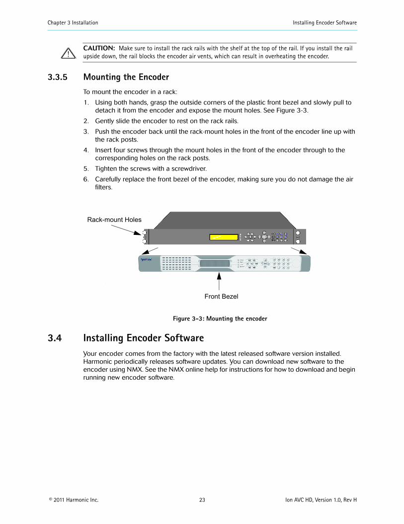
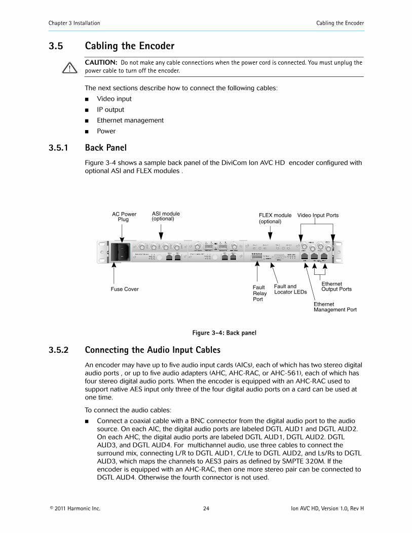
Chapter 3 Installation Cabling the Encoder
copy 2011 Harmonic Inc 26 Ion AVC HD Version 10 Rev H
ATTENTION Pour ce qui est de la protection contre les courts-circuits (surtension) ce produit deacutepend de lrsquoinstallation eacutelectrique du local Veacuterifier qursquoun fusible ou qursquoun disjoncteur de 120 V alt 20 A US maximum (240 V alt 20 A international) est utiliseacute sur les conducteurs de phase (conducteurs de charge)
WARNUNG Dieses Produkt ist darauf angewiesen daszlig im Gebaumlude ein Kurzschluszlig-bzw Uumlberstromschutz installiert ist Stellen sie sicher daszlig eine Sicherung oder ein Unterbrecher von nicht mehr als 240 V Wechselstrom 20 A (bzw in den USA 120 V Wechselstrom 20 A) an den Phasenleitern (allen stromfuumlhrenden Leitern) verwendet wird
To connect the power cord
Connect the power cord to the power plug on the encoder back panel and connect the power cord to the power outlet
CAUTION The power supply cord is used as the main disconnect device Ensure that the socketoutlet is locatedinstalled near the equipment and is easily accessible
ATTENTION Le cordon drsquoalimentation est utiliseacute comme interrupteur geacuteneacuteral La prise de courant doit ecirctre situeacutee ou installeacutee agrave proximiteacute du mateacuteriel et ecirctre facile drsquoacceacutes
WARNUNG Das Netzkabel dient als Netzschalter Stellen sie sicher das die Steckdose einfach zugaumlnglich ist
Power Supply Cord Notice
CAUTION This unit has more than one power supply connectionrsquo all connections must be removed to remove all power from this unit
ATTENTION Cette uniteacute est eacutequipeacutee de plusieurs raccordements dalimentation Pour supprimer tout courant eacutelectrique de luniteacute tous les cordons dalimentation doivent ecirctre deacutebrancheacutes
WARNUNG Diese Einheit verfuumlgt uumlber mehr als einen Stromanschluszlig um Strom gaumlnzlich von der Einheit fernzuhalten muumlssen alle Stromzufuhren abgetrennt sein
Laser warning
Warning Class 1 laser product
Attention Produit laser de classe 1
Warnung Laserprodukt der Klasse 1
copy 2011 Harmonic Inc 27 Ion AVC HD Version 10 Rev H
Chapter 4Operating the Encoder
After installing the encoder in a rack and connecting the cables as described in Chapter 3 Installation configure the encoder platform and services
The chapter describes
How to use NMX Digital Service Manager to configure the Ion AVC HD
How to use the Ion AVC HD front panel
41 Operating with NMX Digital Service ManagerWhen you use NMX Digital Service Manager to manage the encoders in your network you perform all encoder configuration including IP address assignment in NMX You do not need to do any configuration from the encoder front panel
See the NMX online help for instructions for adding an encoder to an NMX network group You will need to know the encoder MAC address when you add the encoder to a network group See 424 Viewing the Encoder MAC Address on page 29 for instructions for viewing the MAC address in the front panel display
42 Using the Front Panel You can perform some initial network configuration from the encoder front panel From the front panel you can set the encoderrsquos IP address default gateway and subnet mask and you can view the encoderrsquos MAC address and serial number
421 The Keypad The keypad on the local control panel provides the following functions
Access to the menus
Navigation through the menu hierarchies to their parameters
Editing capabilities
Figure 4-1 shows the keypad
Hot Keys Navigation andFunction Keys
Alphanumeric Keys
Figure 4-1 Front panel keypad
Seven hot keys provide immediate access to the encoder menus The Network and Help hot keys are currently active The other hot keys are reserved for future use
Chapter 4 Operating the Encoder Using the Front Panel
copy 2011 Harmonic Inc 28 Ion AVC HD Version 10 Rev H
Navigation and function keys located to the right of the hot keys provide a tool for navigating through the menu hierarchies and changing parameter values Use the alphanumeric keys to enter new values
422 Front Panel Display
The two-line 20-character vacuum fluorescent display (VFD) shows the menus parameters and options As illustrated in Figure 4-2 line 1 of the local control panel display shows the menu path for the currently selected option To represent a path the VFD displays each submenu as two or more letters and a colon
Line 2 of the display shows the second line of a help message or a parameter value To change this value you must enter the new value using the keypad
NTWK Control IPParameter Requires
Value to be Edited
Value Setting
19216824101
Figure 4-2 Setting a value in the front panel display
A blinking cursor shows the current value A steady cursor shows the value being edited
Press the Help key to display an online message for the currently selected menu item
423 Setting the Encoder Network PropertiesBefore you can begin to configure the encoder you must set the encoder IP address subnet mask and default gateway The encoder ships with a default IP address based on the encoder serial number The default subnet mask is 255000 and the default gateway address is 10001
4231 Setting the IP Address
To set the encoder management port IP address
1 Press the NTWK hot key
The VFD display shows NTWK Configuration
2 Press the
v key to navigate to NTWK Control IP
3 Press Enter
4 Enter the IP address using the alphanumeric keys
TIP To enter a period press the Shift key and the 0 key
5 When you finish press Enter
Do not exit the Network menu because you can set the other properties from here
Chapter 4 Operating the Encoder Using the Front Panel
copy 2011 Harmonic Inc 29 Ion AVC HD Version 10 Rev H
4232 Setting the Subnet Mask
To set the subnet mask
1 Press the
v key to navigate to NTWK Control Subnet
2 Press Enter
3 Enter the subnet mask using the alphanumeric keys
TIP To enter a period press the Shift key and press the 0 key
4 When you finish press Enter
4233 Setting the Default Gateway Address
To set the gateway address
1 Press the
v
key to navigate to NTWK Gateway
2 Press Enter
3 Enter the default gateway using the alphanumeric keys
TIP To enter a period press the Shift key and press the 0 key
4 When you finish press Enter
5 Press Esc to exit the Network menu
424 Viewing the Encoder MAC Address You can view the encoder MAC address from the front panel
To view the encoder MAC address
1 Press the NTWK hot key
2 Press the
v
key several times to navigate to NTWK Control MAC
The MAC address appears beneath the parameter name
3 Press Esc to exit the parameter
425 Viewing the Encoder Serial NumberYou can view the encoder serial number from the front panel
To view the encoder serial number
1 Press the STAT hot key
2 Press the
v
key to navigate to STAT Serial Number
The serial number appears beneath the parameter name
3 Press Esc to exit the parameter
Chapter 4 Operating the Encoder Licensing Information
copy 2011 Harmonic Inc 30 Ion AVC HD Version 10 Rev H
43 Licensing InformationLicensing is required for some encoding features and you cannot enable those features without the appropriate licensing You can add licenses to your system at any time using the SAG (Web GUI) You must acquire licenses from Harmonic When licenses expire streams will continue to flow as configured but cannot be modified or re-enabled if disabled for any reason Streams that include features under license will raise alarms when their licensing expires Alarms will also be raised to advise you that licensing is required for a given feature if that feature is blocked Also any attempted changes after a license expires may be service affecting and other operations such as redundancy may not operate properly For additional information on using the Configuration Manager for licensing operations refer to your encoderrsquos online help
Under the Licensing tab (on Platform Configuration page) you can
Apply license keys that have been created and sent to you by Harmonic in a lic license file The license file is unique to a specific encoder and can be used on that encoder only once When you apply a license the system scans the encoder platform for the matching devicefeature and binds the license key to that encoder One lic file may contain multiple license keys Every key in the lic file will be applied One license key may unlock multiple instances of a feature There is no undo for applying licenses but you can delete them
Delete a license key and save the deletion receipt for return to Harmonic If you want to remove a license key from one device to use it on another you must delete it When you delete a key the device releases it and a unique deletion receipt is created This receipt must be sent to Harmonic so that the deleted license can be made available in the license database for use in a different encoder There is no undo for deletion You must provide the deletion receipt to Harmonic to make the license available for use again
View the current licenses that are on the encoder platform
To apply licenses
If you ordered a new license you received a file To install it on this encoder follow these steps
1 Click the Add license button The license Loader window opens
2 Type in the path and file name where you saved the new license file or use the Browse button and navigate to it
3 Click the Transfer button The encoder applies all the license keys that are in the lic file and binds them to the encoder The new licenses appear in the license table
4 Disable then re-enable the affected streams if applicable
To delete licenses
Contact Harmonic customer support for more information
copy 2011 Harmonic Inc 31 Ion AVC HD Version 10 Rev H
Chapter 5Maintenance and Troubleshooting
This chapter describes
How to maintain and replace the air filters and fuse
How to contact Harmonic Support
51 Air Filters The encoder uses two air filters to minimize dust and dirt in the circuitry and components in the chassis These filters are made of flexible compressed fiber spun from urethane foam Installed in the front of the encoder the filters are fire retardant and conform to UL 900 Class II specifications
The bezel filter is located inside the front bezel on the left side Figure 5-1 shows the dimensions of the bezel filter The notches on the left side and the cutouts in the middle can fit on either side of the front bezel mounting posts
532 inches
164 025 inchesinches
Figure 5-1 Bezel filter (front view)
The keypad filter is located behind the front panel keypad Figure 5-2 shows the keypad filter
645 inches
025 inches
164inches
Figure 5-2 Keypad filter (front view)
511 Maintaining the Air Filters The operating environment of the encoder plays a large factor in determining the life of the air filters Encoders that operate in dusty and dirty surroundings require more frequent inspections and filter cleaning than those operating in cleaner environments
Inspect and clean the filters with a frequency that is appropriate to the environment in which the encoder operates Harmonic recommends inspecting and cleaning the filters every six weeks to ensure proper airflow through the chassis
To clean dust and dirt from the filters you can use a vacuum cleaner to remove the dirt or you can rinse the filters in water You can also use soaps or mild detergents on the filters If you rinse the filters in water make sure that you squeeze the excess water from them before reinstalling them in the encoder You might need to order replacement filters if the filters become too dirty over time
Chapter 5 Maintenance and Troubleshooting Fuse
copy 2011 Harmonic Inc 32 Ion AVC HD Version 10 Rev H
512 Removing and Replacing the Air Filters You do not need to turn off the encoder when removing and replacing the air filters
5121 Removing and Replacing the Bezel Filter
To remove the front left filter from behind the front bezel
1 Grasp each side of the encoderrsquos front bezel with your hands
2 Carefully remove the front bezel by pulling it away from the encoder
3 Remove the filter from inside the front bezel
4 Inspect the air filter for dirt and clean it if necessary
NOTE When the filter is new its color is medium charcoal As dust and dirt collect in the porous filter material the filterrsquos color gradually changes to brown then an ash color
5 Replace the filter inside the front bezel Place the filter so that the long horizontal slot is at the bottom edge Carefully place the cutouts in the filter around the bezel mounting posts
6 Carefully replace the front bezel on the encoder making sure the filter does not fall out of the bezel
5122 Removing and Replacing the Keypad Filter
To remove the air filter from behind the keypad
1 Grasp each side of the encoder front bezel with your hands
2 Carefully remove the front bezel by pulling it away from the encoder
Note the location of the filter The keypad is screwed onto the front of the encoder through four mounting posts Cutouts on the filter wrap around the four posts and the right side of the filter extends past the keyboard
3 Remove the filter by pulling the left side of the filter up and away from the keyboard mounting posts then pulling up the right side
4 Inspect the air filter for dirt and clean it if necessary
5 Replace the filter by inserting the right side of the filter behind the keypad with the vertical slots around the mounting posts
6 Insert the left side of the filter placing the horizontal cutouts around the mounting posts
7 Carefully replace the front bezel on the encoder making sure the filter does not fall out of the bezel
52 Fuse Encoders use a slow blow 40 A 250 V fuse 5 x 20 mm The fuse is located on the back panel beside the power input A spare fuse is located in the fuse cover shown in Figure 5-3
Fuse cover
Figure 5-3 Fuse cover and AC power input
Chapter 5 Maintenance and Troubleshooting Contacting Harmonic Support
copy 2011 Harmonic Inc 33 Ion AVC HD Version 10 Rev H
521 Replacing the FuseTo replace the fuse
1 Unplug the power cord from the chassis
DANGER You must disconnect the power cord before removing the fuse
2 Pull down the fuse cover on the back panel
3 Remove the old fuse
4 Install the new fuse
DANGER Always replace the fuse with a fuse of the same rating and type Using a different fuse voids the Harmonic warranty and could result in fire or other electrical damage
5 Replace the fuse cover
6 Plug in the encoder
53 Contacting Harmonic SupportThe Harmonic Customer and Technical Support groups are available to help you with any questions or problems you may have regarding Harmonic products
For assistance from within the US and Canada call toll free
1888MPEGTWO (6734896)
For assistance from outside the US and Canada call
14084906477
The fax number is 4084906770
The email address is techhelpharmonicinccom
The corporate address for Harmonic Inc is
Harmonic Inc 549 Baltic Way Sunnyvale CA 94089 USA Attn Customer Support
The corporate telephone numbers for Harmonic Inc are
Tel 18007881330 (from the US and Canada) Tel +14085422500 (outside the US and Canada) Fax+14084906708
The web address for Harmonic Inc is wwwharmonicinccom
copy 2011 Harmonic Inc 34 Ion AVC HD Version 10 Rev H
Appendix AEncoder Specifications
This appendix contains a comprehensive list of the environment and physical characteristics of the encoder electrical specifications and information about the pinouts for the input and output ports
A1 Environment Specifications Table A-1 lists environment specifications for the encoder
Table A-1 Environment Specifications
Parameter Specification
Size 445 cm x 4826 cm x 6069 cm (175 in x 19 in x 24 in)
Weight 11 kg (24 lb)
AC Power
AC 100-240V (auto ranging)
47 to 63 Hz
1 channel (ELC-7011) 108 W 2 channel (ELC-7022) 162 W 3 channel (ELC-7033) 216 W 4 channel (ELC-7044) 270 W
63A 250V fuse 5 x20mm
Temperature
5 to 40 degC (41 to 104 degF)
ndash20 to +80 degC (ndash4 to +176 degF)
Humidity
lt 95 noncondensing
lt 95 noncondensing
Altitude
lt 15000 feet (4572 meters)
lt 40000 feet (12192 meters)
Shock and Vibration
Passes the impact compression and vibration requirements of ASTM D4169-94 Distribution Cycle 13 Assurance Level 1
Passes NEBS Office Vibration Test while operating (01G sine sweep 5 to 100 Hz 3 axis)
Input voltage range
Line frequency
Typical consumption
Fuse
Operating
Storage
Operating
Storage
Operating
Storage
Packaged
Operating
Appendix A Encoder Specifications Port Specifications
copy 2011 Harmonic Inc 35 Ion AVC HD Version 10 Rev H
A2 Port Specifications Table A-2 lists the specifications for the back panel port connections For port locations see the illustration of the back panel on Figure 3-4 on page 24
Table A-2 Port Specifications
Port Connection Specification
Video input port
Serial DigitalSignal format per SMPTE 292M
75 Ω unbalanced
BNC
Ethernet management port
10100 Base-T
8023
RJ-45
Input serial port Reserved for future use
Ethernet output port
101001000 Base-T
MPEG-4 over IP
RJ-45
Fault relay port Capable of switching 025 amps at 30 VDC
Phoenix 1881383
A3 Port Pinouts The following sections describe the Ethernet management and fault relay port pinouts
A31 Ethernet Management Port The Ethernet management port is 10100 Base-T and uses an RJ-45UTP port to connect to an Ethernet network Use this port to manage the encoder with NMX See 355 Connecting the Ethernet Management Cable on page 25 for cabling instructions
Table A-3 lists the pinouts for the RJ-45 Ethernet port
Protocol
Impedance
Connector type
Type
Protocol
Connector type
Type
Protocol
Connector type
Mating connector type
Table A-3 Ethernet Management Port Pinout
Pin Signal
1 Transmit data (TD) +
2 Transmit data (TD) ndash
Appendix A Encoder Specifications Port Pinouts
copy 2011 Harmonic Inc 36 Ion AVC HD Version 10 Rev H
A32 Fault RelayGPI Ports A contact closure is a physical connection between two platforms that define the state of the platform by being either on or off
Both NMX and SAG provide alarm management and redundancy for third party devices through contact closure monitoring Additionaly the contact closure on the Electra and Ion-based encoders can also be used as DPI inputs to the encoder A contact closure is a physical connection (Figure A-1) between two platforms that define the state of the platform by being either on or off Table A-4 lists the fault relay pinouts Individual wires need to be inserted into the contacts and grounded to the ground pin to activate a contact closure When configured in the DPI properties page (of either NMX or the SAG) an SCTE35 message is sent out when that pin is set to low Each is independent and can be provisioned to any one channel and multiple available channels
The fault relay port connects to a Form C relay that can switch up to 025 A at 30 VDC
Table A-4 Fault RelayGPI Port Pinout
Pin Connection
1 Normally closed (NC)
2 Normally open (NO)
3 Common (CM)
4 GPI contact 1
5 GPI contact 2
6 GPI contact 3
7 GPI contact 4
8 Ground (GND)
3 Receive data (RD) +
4 Not connected
5 Not connected
6 Receive data (RD) ndash
7 Not connected
8 Not connected
Table A-3 Ethernet Management Port Pinoutcontinued
Pin Signal
Appendix A Encoder Specifications Port Pinouts
copy 2011 Harmonic Inc 37 Ion AVC HD Version 10 Rev H
Figure A-1 Fault RelayGPI Ports
copy 2011 Harmonic Inc 38 Ion AVC HD Version 10 Rev H
Appendix BAudio and Video Specifications
B1 AIC FeaturesThe AIC adapter accepts analog (balanced or unbalanced) discrete AES3SPDIF digital and AES3 embedded in serial digital video inputs For analog and discrete AES3 inputs sampling frequencies of 48 kHz 441 kHz and 32 kHz are supported Embedded digital is supported only for 48 kHz sampling which must be synchronous to the video
Table B-1 lists the AIC features for each coding mode including the supported sampling frequencies and ES bit rates
Table B-1 AIC Features
AIC Feature Coding Mode SamplingFrequency
ES Bit RatesSupported (Kbps)
MPEG-1 Layer II compression
Single channel (10) 32 kHz 441 kHz 48 kHz
32 48 56 64 80 96 112 128 160 192
Dual channel (1+1) Stereo channel (20) Joint stereo channel
32 kHz 441 kHz 48 kHz
64 96 112 128 160 192 224 256 320 384
MPEG-1 Layer II compression SPPC (separate PID per channel)
Single channel (10) 32 kHz 441 kHz 48 kHz
32 48 56 64 80 96 112 128 160 192
Dolby Digital (AC-3) compression
Single channel (10) 32 kHz 441 kHz 48 kHz
56 64 80 96 112 128 160 192 224 256 320
384 448a 512a 576a
640a
Stereo channel (20) 32 kHz 441 kHz 48 kHz
96 112 128 160 192
224 256 320 384 448a
512a 576a 640a
Dolby Digital (AC-3) passthrough
Up to 51 channels (32+LFE professional 16-bit mode)
32 kHz441 kHz48 kHz
56b 80b 96 112 128 160 192 224 256 320 384
448a 512a 576a 640a
Up to 51 channels (32+LFE professional 32-bit mode)
32 kHz441 kHz48 kHz
256 320 384 448a 512a
576a 640a
Appendix B Audio and Video Specifications AIC Features
copy 2011 Harmonic Inc 39 Ion AVC HD Version 10 Rev H
Note the following limitations
ATSC Standard A53 specifies that only 48 kHz sampling may be used and that ES bit rates must be less than or equal to 384 Kbps for a complete service It also specifies that a two-channel dialog-only service must be less than or equal to 192 Kbps Total ES rates for all services must be less than or equal to 512 Kbps
Embedded audio must be 48 kHz sampling and synchronous with the video See SMPTE 272M for definitions
MPEG AAC and HE AAC can be placed into the output Transport Stream encapsulated in either of two methods
ADTS
ADTS is an acronym for ldquoAudio Data Transport Streamrdquo This is the default used if the user selects MPEG-2 AACHE AAC ADTS is assigned a stream type value of 0x0F
LATMLOAS
LATM is an acronym for rdquoLow Overhead Audio Transport Multiplexrdquo LOAS is an acronym for rdquoLow Overhead Audio Streamrdquo and furnishes an outer wrapper for LATMs inner wrapper of the raw audio Elementary Stream syntax MPEG-4 AAC and HE AAC bitstreams are encapsulated as LATMLOAS and assigned a stream type value of 0x11
Encapsulation mode is controlled by selecting rdquoMPEG-2rdquo or rdquoMPEG-4rdquo as required
MPEG HE AAC compression
Single channel (10) 32 kHz441 kHz48 kHz
32 48 56 64 96
Dual channel (1+1) Stereo channel (20) Joint stereo channel
32 kHz441 kHz48 kHz
32 48 56 64 96 112 128
MPEG AAC compression
Single channel (10) 32 kHz441 kHz48 kHz
32 48 56 64 96 112 128 182 192
Dual channel (1+1) Stereo channel (20) Joint stereo channel
32 kHz441 kHz48 kHz
64 96 112 128 182 192 224 256 320 384
a These rates are not compliant with A53b These rates are valid for 10 coding only
Table B-1 AIC Features continued
AIC Feature Coding Mode SamplingFrequency
ES Bit RatesSupported (Kbps)
Appendix B Audio and Video Specifications Dolby Digital (AC-3) Audio
copy 2011 Harmonic Inc 40 Ion AVC HD Version 10 Rev H
B2 Dolby Digital (AC-3) Audio The Ion AVC HD supports Dolby Digital (AC-3) native audio encoding AIC-equipped encoders support native two-channel Dolby Digital (AC-3) compression AIC-equipped encoders also support Dolby Digital (AC-3) 51 in passthrough mode
NOTE Harmonic supports Dolby Digital (AC-3) passthrough rates of 96 to 640 Kbps and native Dolby Digital (AC-3) rates of 56 to 640 Kbps
Table B-2 lists the bit rates for the sample frequencies of 48 kHz 441 kHz and 32 kHz
Table B-2 Dolby Digital (AC-3) Audio Bit Rates
Audio Bit Rate (Kbps)
Audio without PCR Audio with PCR
48 kHz 441 kHz 32 kHz 48 kHz 441 kHz 32 kHz
56 658 605 627 658 605 627
64 752 691 689 752 691 689
80 846 864 877 846 864 877
96 1034 1036 1003 1034 1036 1065
112 1222 1209 1191 1222 1209 1191
128 1316 1382 1316 1410 1382 1379
160 1692 1641 1692 1692 1727 1692
192 1974 1986 2005 2068 1986 2005
224 2350 2332 2319 2350 2332 2319
256 2632 2677 2632 2726 2677 2695
320 3290 3282 3321 3384 3368 3321
384 3948 3973 3948 4042 3973 3948
448 4606 4664 4637 4606 4664 4637
512 5264 5268 5264 5264 5268 5264
576 5922 5959 5891 5922 5959 5953
640 6580 6564 6580 6580 6564 6580
NOTE Changing from non-single-channel mode to single-channel mode provisions the transport bit rate automatically
When you change between single-channel and non-single-channel modes the encoder automatically provisions the bit rate to the closest available bit rate In some cases this means the bit rate is lower because provisioning does not increase the bit rate defined for the port Therefore changing the coding mode from non-single-channel mode to any of the four highest bit rates causes the encoder to provision the bit rate to 192 Kbps
Appendix B Audio and Video Specifications Video Specifications
copy 2011 Harmonic Inc 41 Ion AVC HD Version 10 Rev H
In the case of the three lowest bit rates when you change from single-channel to non-single-channel mode because the bit rate is the lowest available the encoder provisions to the next highest available bit rate 64 Kbps If you set the bit rate to 80 Kbps and then change the coding mode to non-single-channel the encoder provisions the bit rate to 64 Kbps
B3 Video Specifications The encoder is equipped to handle high definition (HD) serial digital input (SDI)
Table 5-1 Video Specifications
Feature Specification Comments
Input formats Serial digital component High definition serial digital interface (HD-SDI) per SMPTE 292M
VITC support 1080i 30MB 720p 60MB
Import formats supported in HD
B4 VITC SupportThe Ion AVC HD supports extraction of Vertical Interval Time Code (VITC) data placed into VANC or HANC per SMPTE RP188 The VITC data is used to synchonize DPI events on hoth HD and SD encoders HD encoders receive VITC input carried in the Vertical Ancillary data space (VANC) or Horizontal Ancillary data space (HANC) of a 292MB stream
copy 2011 Harmonic Inc 42 Ion AVC HD Version 10 Rev H
Appendix CEncoder Back Panel Slot Locations
C1 Adapter Configurations for All EncodersFigure C-1 represents the back panel of an encoder Table C-1 shows the slot number and the modules that can be installed in encoders that are not associated with a FLEX module Table C-2 shows the slot number and the modules associated with the FLEX module that can be installed NMX uses the slot number to differentiate between adapters of the same type within the encoder
Slot 2
Slot 1 Slot 3
Slot 4 FLEX
Main Board
Slot 5 FLEX
Figure C-1 Slot numbers
Table C-1 shows the adaptersmodules software support and configuration recommendations for non-FLEX based encoders
Table C-1 Supported adaptersmodules and configuration recommendations for this encoder
Adapter Slot Notes
AIC Any slot (1-5 adapters per chassis)
AHC-RAC Any slot (1-5 adapters per chassis)
AHC-561 Slots 1- 4 (1-4 adapters per chassis) Not supported on slot 5 Supported only via NMX
ASI Output Slot 5 without a FLEX module Slot 2 with a FLEX module (1 adapter per chassis)
Only the first two ports are active and are electrical duplicates of each other
AB Power Input switch
Slots 1 and 3 (both)
C11 Additional Adapter Configurations for FLEX-based EncodersTable C-2 lists the adapter configurations available for FLEX-based encoders
Table C-2 FLEX Module Options (for use with FLEX module)
Card Option Notes
FLEX Slot 4 must be populated first slot 5 second (1-2 adapters per chassis)
Requires CPC revision 105 or higher see Viewing the Control Board (CPC) Revision Information on page 43
GbE Slot 1 only (1 adapter per chassis)
Used with FLEX module for input only
Appendix C Encoder Back Panel Slot Locations Adapter Configurations for All Encoders
copy 2011 Harmonic Inc 43 Ion AVC HD Version 10 Rev H
NOTE ASI Input adapters (used with FLEX module) and ASI Output adapters utilize the same hardware but perform different functions based on 1) the slot number and 2) if a FLEX module is installed If installed in slots 2 or 5 the ASI adapter is always an output If a FLEX module is installed an ASI adapter installed in slots 1 or 3 is an input
C12 Viewing the Control Board (CPC) Revision Information1 From the Platform tab click on the Platform link
2 Click on the Control Board (CPC) link
The Control Board (CPC) Configuration page appears
Click on the Maintenance tab to examine the version information
ASI Input Slot 1 (typical) slot 3 if slot 1 isalready in use (1 card perchassis) For FLEX only chassisthe FLEX module goes into slot4 and 5 Slot 4 must bepopulated first For baseband andcompressed mixed inputencoders the FLEX module canbe either slot 4 or 5 ASI inputadapters cannot use slot 4 as itis used for first FLEX module
ASI input is currently only forFLEX module ASI in slots 1 3and 4 appears as an input card
RF 8VSB Slot 1 (typical) or slot 3 if slot 1 is already in use or slot 2 if slots 1 and 3 are already in use (1 adapter per chassis)
Used with FLEX module for input only
Table C-2 FLEX Module Options (for use with FLEX module)
Card Option Notes
copy 2011 Harmonic Inc 44 Ion AVC HD Version 10 Rev H
Appendix DBoot Sequence
This appendix describes the encoder boot sequence including the messages that appear on the local control panel display
D1 Local Control Panel Display Messages during BootupMessages on the local control panel indicate progress during boot-up During a successful boot many events occur so quickly you cannot see the messages The following sections describe the messages that you can see during boot attempts
NOTE During the boot sequence do not press any key on the keypad
The following sequence describes the display on the vacuum fluorescent display (VFD) during a successful startup
Power on
VFD line 1 = Harmonic Inc VFD line 2 = System Loading
Begin loading
VFD line 1 = Divicom Ion AVC HD VFD line 2 = System Loading
Booting
VFD line 1 = Divicom Ion AVC HD VFD line 2 = Loading xxxxxxxxelf
Finished
VFD line 1 = Divicom Ion AVC HD VFD line 2 = Multichannel Encoder
D2 Other Local Control Panel Display MessagesThe local control panel displays messages for other types of restarts including a system reset and loading new software
D21 Resetting the Encoder When you reset the encoder from NMX a message on the VFD shows that the encoder has been reset The encoder uses the boot file on the hard drive when you reset it
Reset from NMX
VFD line 1 = Bye bye VFD line 2 =
After power cycle
VFD line 1 = Harmonic Inc VFD line 2 = System Loading
Begin loading
Appendix D Boot Sequence Other Local Control Panel Display Messages
copy 2011 Harmonic Inc 45 Ion AVC HD Version 10 Rev H
VFD line 1 = Divicom Ion AVC HD VFD line 2 = System Loading
Booting
VFD line 1 = Divicom Ion AVC HD VFD line 2 = Loading xxxxxxxxelf
Finished
VFD line 1 = Divicom Ion AVC HD VFD line 2 = Multichannel Encoder
D22 Loading New Software You can download new software to an encoder using NMX After downloading the software restart the encoder to begin using the new software The following messages appear
Begin loading
VFD line 1 = Divicom Ion AVC HD VFD line 2 = System Loading
Booting
VFD line 1 =Divicom Ion AVC HD VFD line 2 = Loading xxxxxxxxelf
Finished
VFD line 1 = Divicom Ion AVC HD VFD line 2 = Multichannel Encoder
copy 2011 Harmonic Inc 46 Ion AVC HD Version 10 Rev H
Appendix EWiring the ndash48 VDC Power Supply
If your encoder has the optional ndash48 VDC power supply follow these steps to wire the power supply
E1 Getting StartedBefore you begin wiring the ndash48 VDC power supply make sure that you provide the necessary overcurrent protection wires and power connector
E2 Power Source SpecificationsThe DC power source feeding the encoder must meet the following requirements
Electrically isolated from any AC power source
Positive ground The Positive bus of the DC power source must be reliably connected to the Ground bus
Each feed-pair must provide a continuous supply of power that meets the following specifications
Table E-1 Power Source Specifications
Parameter Specification
Voltage 40ndash60 VDC
Max operating current 8 amps
Max input surge current
20 amps
E3 Overcurrent ProtectionTo provide overcurrent protection
Provide overcurrent protection devices as part of each rack housing encoders
Locate a readily accessible disconnect device between the DC power source and the encoder
Use a 10-amp double-pole fast trip DC-rated disconnect device for each DC power connector
NOTE Overcurrent protection devices must meet applicable national and local electrical safety codes and be approved for the intended application
E4 Wiring RequirementsThe encoder is connected to the DC power source using three wires
ndashVin
GND
Appendix E Wiring the ndash48 VDC Power Supply Power Connector
copy 2011 Harmonic Inc 47 Ion AVC HD Version 10 Rev H
+Vin
Although Harmonic provides the power input connector with the encoder you must supply the wires
The wires to be used must comply with the following specifications
Table E-2 Recommended Wire Specifications
Parameter Specification
Suitable conductor material Copper only
ndashVin and +Vin wires 16 AWG rating
Ground cable 16 AWG rating
Cable insulation rating Minimum 80 C low smoke fume (LSF) flame retardant
Cable type Must comply with at least one of the following standards
Branch circuit cable insulation color
Per applicable national electrical codes
E5 Power ConnectorThe encoder is supplied with a special DC power connector plug that matches the DC power socket on the back of the encoder
This connector is made by WAGO model number 231-103037-000
Use only the original connector for connecting the encoder to the DC power source Contact Harmonic Technical Support if you want to use any other type of connector
The following figure shows the connector and its strain relief housing
Figure E-1 CableStrain Relief Housing
E6 Assembling the DC Input Power CableTo assemble the DC input power cable
1 Prepare the power wires as specified in E4 Wiring Requirements on page 46
2 Use the disconnect device to make sure that the power supply from the DC power source to the cables is switched off
UL 1581 (VW-1) - UL style 1028 or equivalent EEE 383 EEE 1202-1991
Appendix E Wiring the ndash48 VDC Power Supply Assembling the DC Input Power Cable
copy 2011 Harmonic Inc 48 Ion AVC HD Version 10 Rev H
CAUTION Turn off the power before proceeding with these instructions
3 Unplug the WAGO power connector from the power socket on the encoder back panel
4 Identify the three wires coming from the DC power source that are used in the connection to the expansion unit
ndashVin
+Vin
GND
5 Strip up to 03 inches (8 mm) of insulation from each of the wires coming from the DC power source
Do not strip more than this length from each wire Stripping more leaves uninsulated wire exposed outside the DC connector after the assembly is complete
6 Insert a small screwdriver into the rectangular hole directly above the hole in the DC connector where you want to insert the first cable and press down on the screwdriver
This opens the cage clamp for this section of the DC plug connector
NOTE WAGO also sells tools specifically designed to open cage clamps easily For more information either visit the WAGO web site at wwwwagocom or call WAGO at 1-800-346-7245 and request information about items 210-250 or 231-131
7 Feed the exposed section of the wire into the matching hole in the DC plug connector
See the pin-out figure below to match wires with the required holes
Figure E-2 Pin Out Specification
8 Repeat steps 5 through 7 for the other two wires to complete the assembly of the DC input cable
NOTE If you need to remove a wire from the DC plug connector insert a small screwdriver into the slot directly above the wire and press down on the screwdriver to free the wire from the cage clamp
copy 2011 Harmonic Inc 49 Ion AVC HD Version 10 Rev H
Appendix FDiviComtrade FLEX Decoding Module
F1 IntroductionThe DiviCom FLEX decoding module delivers video decoding capability and is integrated into either an Electra or Ion encoder chassis (which will be referred to as the ldquohostrdquo encoder) The FLEX decoding module (hereafter referred to as the FLEX module) is a decoding module only (see Figure F-1) A single FLEX module is able to decode up to two (2) incoming channels and an appropriately configured encoder can deliver up to four (4) channels in a single rack-unit (1-RU) The FLEX module decodes MPEG-2 in both standard definition (SD) or high definition (HD) formats thereby eliminating the dependency on ingress formats The FLEX module is a unique gateway designed with the flexibility to deliver any type of pre-compressed video to any host encoder The FLEX module supports both ASI and IP inputs the most efficient interfaces used to route and transport pre-compressed video feeds
NOTE AHC-561 card is not supported for use with FLEX modules
The FLEX module is controlled and configured with the NMX Digital Service Manager application or the Configuration Manager the Web-based GUI The FLEX module also accepts decoded ATSC 8VSB signals from the DiviCom RF Input Card ( DiviComtrade RF Input Adapter on page 74) The FLEX module does not descramble or reconstruct all audio and ancillary data services (such as VBI) on the output port
NOTE The encoder chassis configuration must include an input module for IP The same GbE Pro card are used for both ProStream 1000 muxes and Electra encoders
Figure F-1 FLEX Module Ports
F2 Video Decoding Specifications Table F-1 describes video specifications supported by the Table F-1describes video specifications supported by the FLEX module See the following tables for more information about video and audio compression See the following tables for more information about video and audio compression
Table F-1 Video Decoding Features
Feature Support
Video Decoding MPEG-2 MPML MPEG-2 MPHL
Aspect Ratios 43 and 169
Appendix F DiviComtrade FLEX Decoding Module Audio Passthrough Specifications
copy 2011 Harmonic Inc 50 Ion AVC HD Version 10 Rev H
F3 Audio Passthrough SpecificationsTable F-2 describes the audio passthrough specifications supported by the FLEX module
Table F-2 Audio Passthrough Specifications
Feature Support
Number of channels
Audio formats
Audio processing
Operating modes
Video Formats 480i2997 576i25 720p5994 72050 1080i25 1080i2997
Additional features (available on some specific hosts only)
General HD decode and downcovert to SDSD hosts only Decodes MPEG-2 MPML (480i and 576i)HD hosts only Decodes MPEG-2 MPHL (720p 5060 and 1080i
5060)Specific hosts only ASI input and output available with FLEX module (using
two ASI cards)
8 (however the total passthrough bitrate per FLEX program cannot exceed 4Mbps)
MPEG-1 Layer II Dolby Digital (AC-3) and AAC audio passthrough
MPEG-1 Layer II10 and 20 decode Dolby AC-3 51 and 20 decode
Audio passthrough Audio passthrough of dual channel No Fixed Audio Gain Adjustment for passthrough audio Audio passthrough with repacketization Audio passthrough Silence insertion during CRC errors or buffer underruns
Mono dual channel or decode to stereo joint stereo 51 multichannel (no decode to PCM on audio passthrough)
Table F-1 Video Decoding Features
Feature Support
Appendix F DiviComtrade FLEX Decoding Module Audio Decode Specifications
copy 2011 Harmonic Inc 51 Ion AVC HD Version 10 Rev H
F4 Audio Decode SpecificationsTable F-3 describes the audio decode specifications supported by the FLEX module
Table F-3 FLEX Audio Decode Specifications
Feature Support
Audio Decoding
Decoding Mode
Audio Formats (MPEG-1 Layer II AC-3)
Compression Mode
Additional Support
NOTE Audio leveling is also supported by the FLEX decoding module This feature defines a constant gain adjustment for incoming audio signal
F41 Decoding Resource ConsiderationsA multichannel decode stream counts as 3 stereo decode streams If no downmixing and no dynamic level adjustment is enabled on any stream the absolute maximum number of audio decode streams is 8 allowed in one of these (and only these) combinations
Up to 4 monostereo decode streams per FLEX decoding port
Up to one multichannel audio decode and one stereo decode stream per FLEX decoding port
Up to 2 multichannel audio decode and 2 stereo audio decode streams on the first FLEX decoding port
Up to 8 monostereo decode streams on the first FLEX decoding port (with no audio on second port)
See Table F-4 on page 52 for information on AC-3 resource considerations
Static Level Adjustment Dynamic Level Adjustment
Dolby AC-3 with multichannel decoding and downmixing
Dolby AC-3 Mono and Stereo decoding
Mono and stereo (20)
(AC-3) Line mode and RF line mode
Support for multiple deocde of the same PID (audio decode)
Table F-4 AC-3 Resource Considerations
Input Format Audio Input (into card) Decoding Mode
Multichannel DownMix checkbox
Result
Resource Usage
Equivalent
AC-3
Mono
Mono Available Audio on the left channel Silence on the right channel
Stereoa
Stereo Audio on both channels
3 x Stereo
Multichannel No Audio on the Center channel Silence on all others
3 x Stereo
Stereo
Mon Available (irrelevant for this decoding mode)
Audio on the left channel Silence on the right channel
Stereoa
Stereo Audio on both channels
Multichannel No Audio on both left and right channels Silence on all others
3 x Stereo
AC-3 (continued)
Multichannel
Mono Available (must be enabled for this decoding mode or an alarm is raised and decoding stops)
Multichannel downmix to Mono on the left channel
Stereoa
Stereo Audio on both channels
Multichannel No Audio on both left and right channels Silence on all others
3 x Stereo
Appendix F DiviComtrade FLEX Decoding Module Audio Decode Specifications
copy 2011 Harmonic Inc 52 Ion AVC HD Version 10 Rev H
Appendix F DiviComtrade FLEX Decoding Module Ancillary Data Specifications
copy 2011 Harmonic Inc 53 Ion AVC HD Version 10 Rev H
See Table F-5 on page 53 for information on MPEG-L2 resource considerations
Table F-5 MPEG-L2 Resource Considerations
Input Format Audio Input (into card)
Decoding Mode Result Resource Usage
Equivalent
MPEG-L2
Mono Mono Audio on left channel Silence on right channel StereoStereo
Stereo Mono Audio on both channels
Stereo
F5 Ancillary Data SpecificationsA multichannel encoder equipped with FLEX is essentially receiving and outputting compressed streams Therefore the terminology used regarding ancillary data can be incorrect or misleading VBI data is not applicable to fully digital signals but is used by user habit The FLEX module does not re-create any of the ancillary data it simply passes it intact as packets of bits to the associate encoderrsquos TS output
Table F-6 describes the ancillary data specifications supported by the FLEX module
Table F-6 Ancillary Data Specifications
Feature Support
Vertical Interval Data Services (Pass through only)
WST (Teletext) Inverted WST WSS VPS AFD and bar data VITC Closed Captioning per CEA-608 and 708 AMOL and TV Guide data
Number of channels 4 PIDS
F6 Input SpecificationsTable F-7 describes the input specifications supported by the FLEX module
a Enabling Multichannel downmixing allocates resources for downmixing resulting in resource usage equivalent to 3 x Stereo
Table F-7 Input Specifications
Feature Support
Transport stream Inputs MPEG-2 TS
ASI interface (optional module)
Connector 4x BNC 75 Ω
MPEG format 188 Bytes per TS packet
Appendix F DiviComtrade FLEX Decoding Module Output Specifications
copy 2011 Harmonic Inc 54 Ion AVC HD Version 10 Rev H
F7 Output SpecificationsTable F-8 describes the output specifications supported by the FLEX module
Table F-8 Outputs Specifications
Feature Support
Video Outputs
Connector Type
Embedded Data along the Video
F8 Environmental and Physical Compliant with ROHS Directive 200295EC Refer to the encoder environmental specifications for additional information
Processing 1 MPTSSPTS per port Up to 150 Mbps per port
ASI Ports 4
IP interface (optional module)
Type Gigabit Ethernet
IP ports 2 Independent ports
Connector 2 x copper SFPs
Speed 1 x 1000 Mbps per port
IP encapsulation MPEG-2 TS over UDPIP 1 to 7 TS IP
MPEG format 188 Bytes per TS packet
MPEG-2 TS MPTS and SPTS
Maximum Bit-Rate per Socket
80 Mbps
Addressing Unicast and multicast
Management IGMP ARP and ICMP
Forward Error Correction (FEC)
The FLEX module supports SMTE 2022 Annex C forward error correction (FEC) FEC provides lost packet recovery at the receiving devices
RF Input Card
For specifics see Appendix G on page 74
One (1) per decoded channel with video only SDI or HD-SDI One (1) additional per channel for confidence monitoring only
DIN 1023 (DIN 1023 to BNC adapters available)
No Audio VBI VANC or HANC data embedded The data are embedded into the SDIHD-SDI output
Table F-7 Input Specifications
Feature Support
Appendix F DiviComtrade FLEX Decoding Module Module Slots
copy 2011 Harmonic Inc 55 Ion AVC HD Version 10 Rev H
F9 Module SlotsThe diagram below represents the back panel of typical encoder The diagram shows the slot number and the modules that can be installed in that slot NMX or Configuration Manager uses the slot number to differentiate between cards of the same type within the encoder
Slot 2
Slot 1 Slot 3
Slot 4 FLEX
Main Board
Slot 5 FLEX
F10 Installing the FLEX Decoding ModuleThis section describes how to install the FLEX Decoding Module The modulersquos ports are shown in Figure F-1 on page 49
Host encoders encoders are typically ordered from the factory with the FLEX module already installed However if additional FLEX modules are installed installation of the FLEX module in the field would be required
F1001 ESD Safety Precautions
To protect modules from electrostatic discharge (ESD) follow these safety precautions
Always wear a properly grounded antistatic wrist strap whenever handling the modules
Keep the module inside the antistatic bag until you are ready to install the module in a chassis
F101 Installing a ModuleBefore installing the FLEX module you may need to upgrade the software version on the encoder Contact Harmonic Customer Support to find out which software version you need to install the additional module
There is also a CPC limitation that requires version 105
NOTE Before making changes to the FLEX module make sure the service configuration is cleared before powering down the system Also before installing the FLEX module make sure that the encoder has the appropriate software version installed before installing the module using either NMX or the Configuration Manager
NOTE The FLEX module must be installed in slot 4 (and an optional second module in slot 5) of the encoder
You need a Phillipstrade screwdriver to install the FLEX module
To install the FLEX module
1 Turn off the encoder in which you are installing the module
2 Remove the protective covers from slots 1 through 5 where you are going to install the module (by loosening the two screws with the Phillips screwdriver)
Save the cover for future use
3 While wearing an ESD wrist strap unpack the module from its antistatic protective packing material
Appendix F DiviComtrade FLEX Decoding Module Cabling the FLEX Module
copy 2011 Harmonic Inc 56 Ion AVC HD Version 10 Rev H
CAUTION Unpack and handle the module away from electric motors transformers and other similar machinery
4 Slide the module onto the encoder by lining up the edges of the module with the slots in the chassis
Make sure that the FLEX module goes into the encoder smoothly without binding or scraping other modules The modules should slide easily until you feel the module engage the internal connector and the module is flush with the back of the encoder Do not force the module
5 Tighten the two screws with the screwdriver
NOTE Refer to the encoder guide or online help for information about accommodating the new FLEX module in the encoderrsquos configuration
F11 Cabling the FLEX ModuleThis section describes how to cable the FLEX module Cabling the FLEX module is very straight forward All video and monitor ports are clearly marked The following table lists the ports and required connectors
NOTE Video ports can either be used for loopback or confidence monitoring
Each firmware license ships with two video loopback cables An optional adapter cable can be purchased for use with the monitoring ports You must also have an IP input module installed Figure F-3 on page 57 provides additional information on understanding the encoderrsquos LED color values
F12 Re-Encode Chassis Scenarios This section describes two recommended re-encode chassis scenarios 2- Channel and 4-Channel scenarios
F121 2 - ChannelFigure F-1 on page 49 illustrates a typical 2-channel re-encode chassis cabling assignment This scenario makes use of a base 2-channel encoder chassis Table F-9 describes the port and cable associations
NOTE For the monitor ports there is a DIN to BNC pigtail connector that can be ordered Harmonic Part number FLEX-MON 229-0054067
Table F-9 Port and Cable Assignments (2-channel)
Port Description Connector
Video 1 75 Ω cable DIN 1023
Appendix F DiviComtrade FLEX Decoding Module Re-Encode Chassis Scenarios
copy 2011 Harmonic Inc 57 Ion AVC HD Version 10 Rev H
NOTE The FLEX module must use slot 4
Figure F-2 2 - Channel Re-Encode Chassis (Cable) Scenario
Figure F-3 describes the LED colors and what they represent
720p
Figure F-3 LED Color Chart
Monitor 1 75 Ω cable This output port is used for the loopback cable that feeds an encoder
DIN 1023
Video 2 75Ω cable DIN 1023
Monitor 2 75 Ω cable The second output port can be used as a monitoring and troubleshooting purposes
DIN 1023
IP Module
Audio Module
Audio Module
FLEX Module
Attaches to optional SDI monitor (video only)
Table F-9 Port and Cable Assignments (2-channel)
Appendix F DiviComtrade FLEX Decoding Module Configuring the FLEX Module in NMX
copy 2011 Harmonic Inc 58 Ion AVC HD Version 10 Rev H
F122 4 - ChannelFigure F-4 illustrates a typical 4-channel re-encode chassis cabling assignment This scenario makes use of a base 4-channel encoder chassis
Table F-10 Port and Cable Assignments
Port Description Connector
Video 1 75 Ω cable DIN 1023
Monitor 1 75 Ω cable This output port is used for the loopback cable that feeds an encoder
DIN 1023
Video 2 75Ω cable DIN 1023
Monitor 2 75 Ω cable The second output port can be used as a monitoring and troubleshooting purposes
DIN 1023
Video 3 75Ω cable DIN 1023
Video 4 75Ω cable DIN 1023
IP Module Audio Module
Attaches to optional SDI monitor
FLEX Module
Figure F-4 4 - Channel Re-Encode Chassis (Cable) Scenario
F13 Configuring the FLEX Module in NMXRefer to the NMX online help system for configuring a FLEX module for use in your NMX Digital Service Manager application
copy 2011 Harmonic Inc 59 Ion AVC HD Version 10 Rev H
Appendix GDivicomtrade RF Input Card
This Appendix contains specifications for the DiviCom RF Input card
The RF Input card is a four channel ATSC 8VSB receiver It receives four independent ATSC 8VSB signals on its inputs and outputs four MPEG-2 Transport Streams over the chassis internal bus to one or more FLEX decoding modules The RF Input card does not support analog demodulation
The RF Input card can be managed by either NMX or SAG Figure G-1 on page 59 shows a diagram of the rear panel
Figure G-1 RF Input card
The LED lights show status as shown in Table G-1 on page 59
Table G-1 LED status lights
Display Status
Off Port disabled
Blinking Yellow Loss of synch
Red Packet error rate (PER) threshold exceeded
Steady yellow SNR below threshold
Green Port Enabled no alarms
G1 RF SpecificationsThe RF specifications for the card are listed below
VSB Input 4 Type lsquoFrsquo connectors per IEC 60169-24
Tuning Range VHFUHF (Channels 2-59)
NOTE Tuning range is limited to Channels 2 to 59 by software per the FCCIndustry Canada decisions to release channels 60 to 69 for public safety use
Sensitivity --83 dBm6 MHz
Dynamic Range gt 80dB
Appendix G Divicomtrade RF Input Card Output Specifications
copy 2011 Harmonic Inc 60 Ion AVC HD Version 10 Rev H
G2 Output SpecificationsThe output specification for the card is
Four MPEG-2 Transport Streams per ATSC A53 Part 3 and ISOIEC 13818-1
G3 Environmental and Physical Compliant with ROHS Directive 200295EC Refer to the encoder environmental specifications for additional information
copy 2011 Harmonic Inc 61 Ion AVC HD Version 10 Rev H
Appendix HAB Power Switch
H1 IntroductionThis appendix contains specifications for the AB Power switch
The AB Power switch receives two separate AC main input sources (to support redundancy) monitors the voltage and selects the good voltage to provide one AC output for input into either the AC or DC power supply The AB Power switch automatically changes from the line A input to the Line B input (or the reverse) upon loss of power on the active line The AB Power switch uses and monitors the active line continuously and switches to the backup port only when the active line has a fault The card switches back automatically when the active port is detected as normal and stable (with an appropriate delay)
NOTE The AB Power switch is a dual-height card and can only be installed in slots 1 and 3
The AB Power switch can be managed by SAG Figure H-1 shows a illustration of the AB Power switch
Pigtail power output cable(plugs into encoder)
Figure H-1 AB Power switch
Appendix H AB Power Switch Card Status
copy 2011 Harmonic Inc 62 Ion AVC HD Version 10 Rev H
H2 Card StatusThis section describes how to recognize the current status of the AB Power switch through its LEDs
NOTE It is recommended that you use A for primary equipment and B for backup equipment
The LED lights show card status as shown in Table H-1 on page 62
Table H-1 LED status lights
Display Status
Red Input power (for that port) is not within the acceptable voltage range
Green Steady input power for that port is within acceptable voltage rangeFlashing port is being utilized for input power
Orange Port failure (canrsquot be used)
Off No power or broken LED
copy 2011 Harmonic Inc 63 Ion AVC HD Version 10 Rev H
AAC power supply
connecting 25overview 17
agency approvals 4air filters 31 to 32airflow 21alphanumeric keys 27audio cables connecting 24audio compression rates described 40audio encoding features 13
Bback panel
described 16Ethernet management port 18 35fault relay port 18fuse 17IP output port 18LEDs 18port specifications 35serial data port 18video input ports 17
boot sequence 44
Ccabling the encoder 24compliance and approval 2connecting
audio input cables 24DC power supply 46Ethernet management cable 25IP output cables 25video input cables 25
connections FCC compliance 2connectors
AC power 17Ethernet 18 35fault relay 36IP output 18RJ-45 18 35video 35
cTUVus North American safety approval 4
DDC power supply 46digital program insertion 14display front panel 28Dolby Digital AC-3 bit rates 40DPI 14
Eenvironmental specifications 34Ethernet management port
connecting cable 25described 18specifications 35
European EMIEMC approvals 4
Ffault relay port 18 36FCC compliance 2features
audio encoding 13general 10video encoding 12
filters See air filters 31front bezel 15
removing 23front panel 15 27front panel display 28function keys 27fuse 32
Hhardware specifications 34Harmonic equipment modifying 2Harmonic Heartbeat Protocol 14help displaying on VFD 28HHP 14hot keys 27
Iinstalling the encoder 20IP output port
connecting cables 25described 18
Kkeypad 27
LLEDs
audio port 19back panel 18front panel 15video port 19
loading new software 45local control panel
described 15display 28
MMAC address viewing 29maintaining air filters 31maintaining fuse 32
Nnavigation keys 27North American EMI approvals 4North American Safety approvals 4
Ooutput port IP 18 25
Ppinouts port 35port specifications 35ports
Ethernet management 18
Index
Index
copy 2011 Harmonic Inc 64 Ion AVC HD Version 10 Rev H
fault relay 18IP output 18serial data 18video input 17
power supplyAC 25DC 46specifications 34
Rrack mounting 20rack rails attaching 22rack-mount kit 20replacing air filters 32resetting the encoder 44RJ-45 connectors 18 35
Sserial data port 18specifications
environment 34fuse 34hardware 34input and output 35port 35power supply 34video 41
standards and approvals 4
TTUV European safety approval 4
Uunpacking the encoder 20
VVFD
display during boot 44paths represented 28
video encoding features 12video input ports
connecting cables 25description 17LEDs 19
video specifications 41
WWEEE compliance 2
Harmonic Inc4300 North First StreetSan Jose CA 95134 USAT +1 408 542 2500 F +1 408 490 6708
wwwharmonicinccom
copy Copyright 2011 Manual Part No MAN-AVC-HD-INST-01
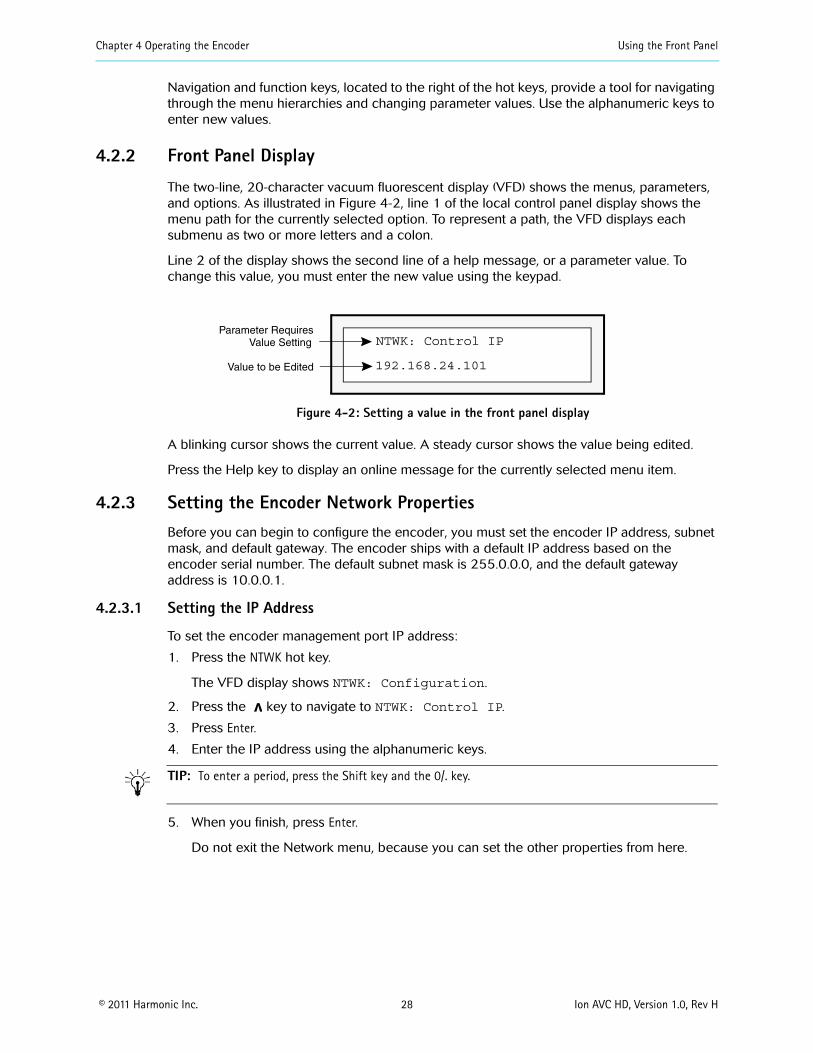
Chapter 4 Operating the Encoder Using the Front Panel
copy 2011 Harmonic Inc 28 Ion AVC HD Version 10 Rev H
Navigation and function keys located to the right of the hot keys provide a tool for navigating through the menu hierarchies and changing parameter values Use the alphanumeric keys to enter new values
422 Front Panel Display
The two-line 20-character vacuum fluorescent display (VFD) shows the menus parameters and options As illustrated in Figure 4-2 line 1 of the local control panel display shows the menu path for the currently selected option To represent a path the VFD displays each submenu as two or more letters and a colon
Line 2 of the display shows the second line of a help message or a parameter value To change this value you must enter the new value using the keypad
NTWK Control IPParameter Requires
Value to be Edited
Value Setting
19216824101
Figure 4-2 Setting a value in the front panel display
A blinking cursor shows the current value A steady cursor shows the value being edited
Press the Help key to display an online message for the currently selected menu item
423 Setting the Encoder Network PropertiesBefore you can begin to configure the encoder you must set the encoder IP address subnet mask and default gateway The encoder ships with a default IP address based on the encoder serial number The default subnet mask is 255000 and the default gateway address is 10001
4231 Setting the IP Address
To set the encoder management port IP address
1 Press the NTWK hot key
The VFD display shows NTWK Configuration
2 Press the
v key to navigate to NTWK Control IP
3 Press Enter
4 Enter the IP address using the alphanumeric keys
TIP To enter a period press the Shift key and the 0 key
5 When you finish press Enter
Do not exit the Network menu because you can set the other properties from here
Chapter 4 Operating the Encoder Using the Front Panel
copy 2011 Harmonic Inc 29 Ion AVC HD Version 10 Rev H
4232 Setting the Subnet Mask
To set the subnet mask
1 Press the
v key to navigate to NTWK Control Subnet
2 Press Enter
3 Enter the subnet mask using the alphanumeric keys
TIP To enter a period press the Shift key and press the 0 key
4 When you finish press Enter
4233 Setting the Default Gateway Address
To set the gateway address
1 Press the
v
key to navigate to NTWK Gateway
2 Press Enter
3 Enter the default gateway using the alphanumeric keys
TIP To enter a period press the Shift key and press the 0 key
4 When you finish press Enter
5 Press Esc to exit the Network menu
424 Viewing the Encoder MAC Address You can view the encoder MAC address from the front panel
To view the encoder MAC address
1 Press the NTWK hot key
2 Press the
v
key several times to navigate to NTWK Control MAC
The MAC address appears beneath the parameter name
3 Press Esc to exit the parameter
425 Viewing the Encoder Serial NumberYou can view the encoder serial number from the front panel
To view the encoder serial number
1 Press the STAT hot key
2 Press the
v
key to navigate to STAT Serial Number
The serial number appears beneath the parameter name
3 Press Esc to exit the parameter
Chapter 4 Operating the Encoder Licensing Information
copy 2011 Harmonic Inc 30 Ion AVC HD Version 10 Rev H
43 Licensing InformationLicensing is required for some encoding features and you cannot enable those features without the appropriate licensing You can add licenses to your system at any time using the SAG (Web GUI) You must acquire licenses from Harmonic When licenses expire streams will continue to flow as configured but cannot be modified or re-enabled if disabled for any reason Streams that include features under license will raise alarms when their licensing expires Alarms will also be raised to advise you that licensing is required for a given feature if that feature is blocked Also any attempted changes after a license expires may be service affecting and other operations such as redundancy may not operate properly For additional information on using the Configuration Manager for licensing operations refer to your encoderrsquos online help
Under the Licensing tab (on Platform Configuration page) you can
Apply license keys that have been created and sent to you by Harmonic in a lic license file The license file is unique to a specific encoder and can be used on that encoder only once When you apply a license the system scans the encoder platform for the matching devicefeature and binds the license key to that encoder One lic file may contain multiple license keys Every key in the lic file will be applied One license key may unlock multiple instances of a feature There is no undo for applying licenses but you can delete them
Delete a license key and save the deletion receipt for return to Harmonic If you want to remove a license key from one device to use it on another you must delete it When you delete a key the device releases it and a unique deletion receipt is created This receipt must be sent to Harmonic so that the deleted license can be made available in the license database for use in a different encoder There is no undo for deletion You must provide the deletion receipt to Harmonic to make the license available for use again
View the current licenses that are on the encoder platform
To apply licenses
If you ordered a new license you received a file To install it on this encoder follow these steps
1 Click the Add license button The license Loader window opens
2 Type in the path and file name where you saved the new license file or use the Browse button and navigate to it
3 Click the Transfer button The encoder applies all the license keys that are in the lic file and binds them to the encoder The new licenses appear in the license table
4 Disable then re-enable the affected streams if applicable
To delete licenses
Contact Harmonic customer support for more information
copy 2011 Harmonic Inc 31 Ion AVC HD Version 10 Rev H
Chapter 5Maintenance and Troubleshooting
This chapter describes
How to maintain and replace the air filters and fuse
How to contact Harmonic Support
51 Air Filters The encoder uses two air filters to minimize dust and dirt in the circuitry and components in the chassis These filters are made of flexible compressed fiber spun from urethane foam Installed in the front of the encoder the filters are fire retardant and conform to UL 900 Class II specifications
The bezel filter is located inside the front bezel on the left side Figure 5-1 shows the dimensions of the bezel filter The notches on the left side and the cutouts in the middle can fit on either side of the front bezel mounting posts
532 inches
164 025 inchesinches
Figure 5-1 Bezel filter (front view)
The keypad filter is located behind the front panel keypad Figure 5-2 shows the keypad filter
645 inches
025 inches
164inches
Figure 5-2 Keypad filter (front view)
511 Maintaining the Air Filters The operating environment of the encoder plays a large factor in determining the life of the air filters Encoders that operate in dusty and dirty surroundings require more frequent inspections and filter cleaning than those operating in cleaner environments
Inspect and clean the filters with a frequency that is appropriate to the environment in which the encoder operates Harmonic recommends inspecting and cleaning the filters every six weeks to ensure proper airflow through the chassis
To clean dust and dirt from the filters you can use a vacuum cleaner to remove the dirt or you can rinse the filters in water You can also use soaps or mild detergents on the filters If you rinse the filters in water make sure that you squeeze the excess water from them before reinstalling them in the encoder You might need to order replacement filters if the filters become too dirty over time
Chapter 5 Maintenance and Troubleshooting Fuse
copy 2011 Harmonic Inc 32 Ion AVC HD Version 10 Rev H
512 Removing and Replacing the Air Filters You do not need to turn off the encoder when removing and replacing the air filters
5121 Removing and Replacing the Bezel Filter
To remove the front left filter from behind the front bezel
1 Grasp each side of the encoderrsquos front bezel with your hands
2 Carefully remove the front bezel by pulling it away from the encoder
3 Remove the filter from inside the front bezel
4 Inspect the air filter for dirt and clean it if necessary
NOTE When the filter is new its color is medium charcoal As dust and dirt collect in the porous filter material the filterrsquos color gradually changes to brown then an ash color
5 Replace the filter inside the front bezel Place the filter so that the long horizontal slot is at the bottom edge Carefully place the cutouts in the filter around the bezel mounting posts
6 Carefully replace the front bezel on the encoder making sure the filter does not fall out of the bezel
5122 Removing and Replacing the Keypad Filter
To remove the air filter from behind the keypad
1 Grasp each side of the encoder front bezel with your hands
2 Carefully remove the front bezel by pulling it away from the encoder
Note the location of the filter The keypad is screwed onto the front of the encoder through four mounting posts Cutouts on the filter wrap around the four posts and the right side of the filter extends past the keyboard
3 Remove the filter by pulling the left side of the filter up and away from the keyboard mounting posts then pulling up the right side
4 Inspect the air filter for dirt and clean it if necessary
5 Replace the filter by inserting the right side of the filter behind the keypad with the vertical slots around the mounting posts
6 Insert the left side of the filter placing the horizontal cutouts around the mounting posts
7 Carefully replace the front bezel on the encoder making sure the filter does not fall out of the bezel
52 Fuse Encoders use a slow blow 40 A 250 V fuse 5 x 20 mm The fuse is located on the back panel beside the power input A spare fuse is located in the fuse cover shown in Figure 5-3
Fuse cover
Figure 5-3 Fuse cover and AC power input
Chapter 5 Maintenance and Troubleshooting Contacting Harmonic Support
copy 2011 Harmonic Inc 33 Ion AVC HD Version 10 Rev H
521 Replacing the FuseTo replace the fuse
1 Unplug the power cord from the chassis
DANGER You must disconnect the power cord before removing the fuse
2 Pull down the fuse cover on the back panel
3 Remove the old fuse
4 Install the new fuse
DANGER Always replace the fuse with a fuse of the same rating and type Using a different fuse voids the Harmonic warranty and could result in fire or other electrical damage
5 Replace the fuse cover
6 Plug in the encoder
53 Contacting Harmonic SupportThe Harmonic Customer and Technical Support groups are available to help you with any questions or problems you may have regarding Harmonic products
For assistance from within the US and Canada call toll free
1888MPEGTWO (6734896)
For assistance from outside the US and Canada call
14084906477
The fax number is 4084906770
The email address is techhelpharmonicinccom
The corporate address for Harmonic Inc is
Harmonic Inc 549 Baltic Way Sunnyvale CA 94089 USA Attn Customer Support
The corporate telephone numbers for Harmonic Inc are
Tel 18007881330 (from the US and Canada) Tel +14085422500 (outside the US and Canada) Fax+14084906708
The web address for Harmonic Inc is wwwharmonicinccom
copy 2011 Harmonic Inc 34 Ion AVC HD Version 10 Rev H
Appendix AEncoder Specifications
This appendix contains a comprehensive list of the environment and physical characteristics of the encoder electrical specifications and information about the pinouts for the input and output ports
A1 Environment Specifications Table A-1 lists environment specifications for the encoder
Table A-1 Environment Specifications
Parameter Specification
Size 445 cm x 4826 cm x 6069 cm (175 in x 19 in x 24 in)
Weight 11 kg (24 lb)
AC Power
AC 100-240V (auto ranging)
47 to 63 Hz
1 channel (ELC-7011) 108 W 2 channel (ELC-7022) 162 W 3 channel (ELC-7033) 216 W 4 channel (ELC-7044) 270 W
63A 250V fuse 5 x20mm
Temperature
5 to 40 degC (41 to 104 degF)
ndash20 to +80 degC (ndash4 to +176 degF)
Humidity
lt 95 noncondensing
lt 95 noncondensing
Altitude
lt 15000 feet (4572 meters)
lt 40000 feet (12192 meters)
Shock and Vibration
Passes the impact compression and vibration requirements of ASTM D4169-94 Distribution Cycle 13 Assurance Level 1
Passes NEBS Office Vibration Test while operating (01G sine sweep 5 to 100 Hz 3 axis)
Input voltage range
Line frequency
Typical consumption
Fuse
Operating
Storage
Operating
Storage
Operating
Storage
Packaged
Operating
Appendix A Encoder Specifications Port Specifications
copy 2011 Harmonic Inc 35 Ion AVC HD Version 10 Rev H
A2 Port Specifications Table A-2 lists the specifications for the back panel port connections For port locations see the illustration of the back panel on Figure 3-4 on page 24
Table A-2 Port Specifications
Port Connection Specification
Video input port
Serial DigitalSignal format per SMPTE 292M
75 Ω unbalanced
BNC
Ethernet management port
10100 Base-T
8023
RJ-45
Input serial port Reserved for future use
Ethernet output port
101001000 Base-T
MPEG-4 over IP
RJ-45
Fault relay port Capable of switching 025 amps at 30 VDC
Phoenix 1881383
A3 Port Pinouts The following sections describe the Ethernet management and fault relay port pinouts
A31 Ethernet Management Port The Ethernet management port is 10100 Base-T and uses an RJ-45UTP port to connect to an Ethernet network Use this port to manage the encoder with NMX See 355 Connecting the Ethernet Management Cable on page 25 for cabling instructions
Table A-3 lists the pinouts for the RJ-45 Ethernet port
Protocol
Impedance
Connector type
Type
Protocol
Connector type
Type
Protocol
Connector type
Mating connector type
Table A-3 Ethernet Management Port Pinout
Pin Signal
1 Transmit data (TD) +
2 Transmit data (TD) ndash
Appendix A Encoder Specifications Port Pinouts
copy 2011 Harmonic Inc 36 Ion AVC HD Version 10 Rev H
A32 Fault RelayGPI Ports A contact closure is a physical connection between two platforms that define the state of the platform by being either on or off
Both NMX and SAG provide alarm management and redundancy for third party devices through contact closure monitoring Additionaly the contact closure on the Electra and Ion-based encoders can also be used as DPI inputs to the encoder A contact closure is a physical connection (Figure A-1) between two platforms that define the state of the platform by being either on or off Table A-4 lists the fault relay pinouts Individual wires need to be inserted into the contacts and grounded to the ground pin to activate a contact closure When configured in the DPI properties page (of either NMX or the SAG) an SCTE35 message is sent out when that pin is set to low Each is independent and can be provisioned to any one channel and multiple available channels
The fault relay port connects to a Form C relay that can switch up to 025 A at 30 VDC
Table A-4 Fault RelayGPI Port Pinout
Pin Connection
1 Normally closed (NC)
2 Normally open (NO)
3 Common (CM)
4 GPI contact 1
5 GPI contact 2
6 GPI contact 3
7 GPI contact 4
8 Ground (GND)
3 Receive data (RD) +
4 Not connected
5 Not connected
6 Receive data (RD) ndash
7 Not connected
8 Not connected
Table A-3 Ethernet Management Port Pinoutcontinued
Pin Signal
Appendix A Encoder Specifications Port Pinouts
copy 2011 Harmonic Inc 37 Ion AVC HD Version 10 Rev H
Figure A-1 Fault RelayGPI Ports
copy 2011 Harmonic Inc 38 Ion AVC HD Version 10 Rev H
Appendix BAudio and Video Specifications
B1 AIC FeaturesThe AIC adapter accepts analog (balanced or unbalanced) discrete AES3SPDIF digital and AES3 embedded in serial digital video inputs For analog and discrete AES3 inputs sampling frequencies of 48 kHz 441 kHz and 32 kHz are supported Embedded digital is supported only for 48 kHz sampling which must be synchronous to the video
Table B-1 lists the AIC features for each coding mode including the supported sampling frequencies and ES bit rates
Table B-1 AIC Features
AIC Feature Coding Mode SamplingFrequency
ES Bit RatesSupported (Kbps)
MPEG-1 Layer II compression
Single channel (10) 32 kHz 441 kHz 48 kHz
32 48 56 64 80 96 112 128 160 192
Dual channel (1+1) Stereo channel (20) Joint stereo channel
32 kHz 441 kHz 48 kHz
64 96 112 128 160 192 224 256 320 384
MPEG-1 Layer II compression SPPC (separate PID per channel)
Single channel (10) 32 kHz 441 kHz 48 kHz
32 48 56 64 80 96 112 128 160 192
Dolby Digital (AC-3) compression
Single channel (10) 32 kHz 441 kHz 48 kHz
56 64 80 96 112 128 160 192 224 256 320
384 448a 512a 576a
640a
Stereo channel (20) 32 kHz 441 kHz 48 kHz
96 112 128 160 192
224 256 320 384 448a
512a 576a 640a
Dolby Digital (AC-3) passthrough
Up to 51 channels (32+LFE professional 16-bit mode)
32 kHz441 kHz48 kHz
56b 80b 96 112 128 160 192 224 256 320 384
448a 512a 576a 640a
Up to 51 channels (32+LFE professional 32-bit mode)
32 kHz441 kHz48 kHz
256 320 384 448a 512a
576a 640a
Appendix B Audio and Video Specifications AIC Features
copy 2011 Harmonic Inc 39 Ion AVC HD Version 10 Rev H
Note the following limitations
ATSC Standard A53 specifies that only 48 kHz sampling may be used and that ES bit rates must be less than or equal to 384 Kbps for a complete service It also specifies that a two-channel dialog-only service must be less than or equal to 192 Kbps Total ES rates for all services must be less than or equal to 512 Kbps
Embedded audio must be 48 kHz sampling and synchronous with the video See SMPTE 272M for definitions
MPEG AAC and HE AAC can be placed into the output Transport Stream encapsulated in either of two methods
ADTS
ADTS is an acronym for ldquoAudio Data Transport Streamrdquo This is the default used if the user selects MPEG-2 AACHE AAC ADTS is assigned a stream type value of 0x0F
LATMLOAS
LATM is an acronym for rdquoLow Overhead Audio Transport Multiplexrdquo LOAS is an acronym for rdquoLow Overhead Audio Streamrdquo and furnishes an outer wrapper for LATMs inner wrapper of the raw audio Elementary Stream syntax MPEG-4 AAC and HE AAC bitstreams are encapsulated as LATMLOAS and assigned a stream type value of 0x11
Encapsulation mode is controlled by selecting rdquoMPEG-2rdquo or rdquoMPEG-4rdquo as required
MPEG HE AAC compression
Single channel (10) 32 kHz441 kHz48 kHz
32 48 56 64 96
Dual channel (1+1) Stereo channel (20) Joint stereo channel
32 kHz441 kHz48 kHz
32 48 56 64 96 112 128
MPEG AAC compression
Single channel (10) 32 kHz441 kHz48 kHz
32 48 56 64 96 112 128 182 192
Dual channel (1+1) Stereo channel (20) Joint stereo channel
32 kHz441 kHz48 kHz
64 96 112 128 182 192 224 256 320 384
a These rates are not compliant with A53b These rates are valid for 10 coding only
Table B-1 AIC Features continued
AIC Feature Coding Mode SamplingFrequency
ES Bit RatesSupported (Kbps)
Appendix B Audio and Video Specifications Dolby Digital (AC-3) Audio
copy 2011 Harmonic Inc 40 Ion AVC HD Version 10 Rev H
B2 Dolby Digital (AC-3) Audio The Ion AVC HD supports Dolby Digital (AC-3) native audio encoding AIC-equipped encoders support native two-channel Dolby Digital (AC-3) compression AIC-equipped encoders also support Dolby Digital (AC-3) 51 in passthrough mode
NOTE Harmonic supports Dolby Digital (AC-3) passthrough rates of 96 to 640 Kbps and native Dolby Digital (AC-3) rates of 56 to 640 Kbps
Table B-2 lists the bit rates for the sample frequencies of 48 kHz 441 kHz and 32 kHz
Table B-2 Dolby Digital (AC-3) Audio Bit Rates
Audio Bit Rate (Kbps)
Audio without PCR Audio with PCR
48 kHz 441 kHz 32 kHz 48 kHz 441 kHz 32 kHz
56 658 605 627 658 605 627
64 752 691 689 752 691 689
80 846 864 877 846 864 877
96 1034 1036 1003 1034 1036 1065
112 1222 1209 1191 1222 1209 1191
128 1316 1382 1316 1410 1382 1379
160 1692 1641 1692 1692 1727 1692
192 1974 1986 2005 2068 1986 2005
224 2350 2332 2319 2350 2332 2319
256 2632 2677 2632 2726 2677 2695
320 3290 3282 3321 3384 3368 3321
384 3948 3973 3948 4042 3973 3948
448 4606 4664 4637 4606 4664 4637
512 5264 5268 5264 5264 5268 5264
576 5922 5959 5891 5922 5959 5953
640 6580 6564 6580 6580 6564 6580
NOTE Changing from non-single-channel mode to single-channel mode provisions the transport bit rate automatically
When you change between single-channel and non-single-channel modes the encoder automatically provisions the bit rate to the closest available bit rate In some cases this means the bit rate is lower because provisioning does not increase the bit rate defined for the port Therefore changing the coding mode from non-single-channel mode to any of the four highest bit rates causes the encoder to provision the bit rate to 192 Kbps
Appendix B Audio and Video Specifications Video Specifications
copy 2011 Harmonic Inc 41 Ion AVC HD Version 10 Rev H
In the case of the three lowest bit rates when you change from single-channel to non-single-channel mode because the bit rate is the lowest available the encoder provisions to the next highest available bit rate 64 Kbps If you set the bit rate to 80 Kbps and then change the coding mode to non-single-channel the encoder provisions the bit rate to 64 Kbps
B3 Video Specifications The encoder is equipped to handle high definition (HD) serial digital input (SDI)
Table 5-1 Video Specifications
Feature Specification Comments
Input formats Serial digital component High definition serial digital interface (HD-SDI) per SMPTE 292M
VITC support 1080i 30MB 720p 60MB
Import formats supported in HD
B4 VITC SupportThe Ion AVC HD supports extraction of Vertical Interval Time Code (VITC) data placed into VANC or HANC per SMPTE RP188 The VITC data is used to synchonize DPI events on hoth HD and SD encoders HD encoders receive VITC input carried in the Vertical Ancillary data space (VANC) or Horizontal Ancillary data space (HANC) of a 292MB stream
copy 2011 Harmonic Inc 42 Ion AVC HD Version 10 Rev H
Appendix CEncoder Back Panel Slot Locations
C1 Adapter Configurations for All EncodersFigure C-1 represents the back panel of an encoder Table C-1 shows the slot number and the modules that can be installed in encoders that are not associated with a FLEX module Table C-2 shows the slot number and the modules associated with the FLEX module that can be installed NMX uses the slot number to differentiate between adapters of the same type within the encoder
Slot 2
Slot 1 Slot 3
Slot 4 FLEX
Main Board
Slot 5 FLEX
Figure C-1 Slot numbers
Table C-1 shows the adaptersmodules software support and configuration recommendations for non-FLEX based encoders
Table C-1 Supported adaptersmodules and configuration recommendations for this encoder
Adapter Slot Notes
AIC Any slot (1-5 adapters per chassis)
AHC-RAC Any slot (1-5 adapters per chassis)
AHC-561 Slots 1- 4 (1-4 adapters per chassis) Not supported on slot 5 Supported only via NMX
ASI Output Slot 5 without a FLEX module Slot 2 with a FLEX module (1 adapter per chassis)
Only the first two ports are active and are electrical duplicates of each other
AB Power Input switch
Slots 1 and 3 (both)
C11 Additional Adapter Configurations for FLEX-based EncodersTable C-2 lists the adapter configurations available for FLEX-based encoders
Table C-2 FLEX Module Options (for use with FLEX module)
Card Option Notes
FLEX Slot 4 must be populated first slot 5 second (1-2 adapters per chassis)
Requires CPC revision 105 or higher see Viewing the Control Board (CPC) Revision Information on page 43
GbE Slot 1 only (1 adapter per chassis)
Used with FLEX module for input only
Appendix C Encoder Back Panel Slot Locations Adapter Configurations for All Encoders
copy 2011 Harmonic Inc 43 Ion AVC HD Version 10 Rev H
NOTE ASI Input adapters (used with FLEX module) and ASI Output adapters utilize the same hardware but perform different functions based on 1) the slot number and 2) if a FLEX module is installed If installed in slots 2 or 5 the ASI adapter is always an output If a FLEX module is installed an ASI adapter installed in slots 1 or 3 is an input
C12 Viewing the Control Board (CPC) Revision Information1 From the Platform tab click on the Platform link
2 Click on the Control Board (CPC) link
The Control Board (CPC) Configuration page appears
Click on the Maintenance tab to examine the version information
ASI Input Slot 1 (typical) slot 3 if slot 1 isalready in use (1 card perchassis) For FLEX only chassisthe FLEX module goes into slot4 and 5 Slot 4 must bepopulated first For baseband andcompressed mixed inputencoders the FLEX module canbe either slot 4 or 5 ASI inputadapters cannot use slot 4 as itis used for first FLEX module
ASI input is currently only forFLEX module ASI in slots 1 3and 4 appears as an input card
RF 8VSB Slot 1 (typical) or slot 3 if slot 1 is already in use or slot 2 if slots 1 and 3 are already in use (1 adapter per chassis)
Used with FLEX module for input only
Table C-2 FLEX Module Options (for use with FLEX module)
Card Option Notes
copy 2011 Harmonic Inc 44 Ion AVC HD Version 10 Rev H
Appendix DBoot Sequence
This appendix describes the encoder boot sequence including the messages that appear on the local control panel display
D1 Local Control Panel Display Messages during BootupMessages on the local control panel indicate progress during boot-up During a successful boot many events occur so quickly you cannot see the messages The following sections describe the messages that you can see during boot attempts
NOTE During the boot sequence do not press any key on the keypad
The following sequence describes the display on the vacuum fluorescent display (VFD) during a successful startup
Power on
VFD line 1 = Harmonic Inc VFD line 2 = System Loading
Begin loading
VFD line 1 = Divicom Ion AVC HD VFD line 2 = System Loading
Booting
VFD line 1 = Divicom Ion AVC HD VFD line 2 = Loading xxxxxxxxelf
Finished
VFD line 1 = Divicom Ion AVC HD VFD line 2 = Multichannel Encoder
D2 Other Local Control Panel Display MessagesThe local control panel displays messages for other types of restarts including a system reset and loading new software
D21 Resetting the Encoder When you reset the encoder from NMX a message on the VFD shows that the encoder has been reset The encoder uses the boot file on the hard drive when you reset it
Reset from NMX
VFD line 1 = Bye bye VFD line 2 =
After power cycle
VFD line 1 = Harmonic Inc VFD line 2 = System Loading
Begin loading
Appendix D Boot Sequence Other Local Control Panel Display Messages
copy 2011 Harmonic Inc 45 Ion AVC HD Version 10 Rev H
VFD line 1 = Divicom Ion AVC HD VFD line 2 = System Loading
Booting
VFD line 1 = Divicom Ion AVC HD VFD line 2 = Loading xxxxxxxxelf
Finished
VFD line 1 = Divicom Ion AVC HD VFD line 2 = Multichannel Encoder
D22 Loading New Software You can download new software to an encoder using NMX After downloading the software restart the encoder to begin using the new software The following messages appear
Begin loading
VFD line 1 = Divicom Ion AVC HD VFD line 2 = System Loading
Booting
VFD line 1 =Divicom Ion AVC HD VFD line 2 = Loading xxxxxxxxelf
Finished
VFD line 1 = Divicom Ion AVC HD VFD line 2 = Multichannel Encoder
copy 2011 Harmonic Inc 46 Ion AVC HD Version 10 Rev H
Appendix EWiring the ndash48 VDC Power Supply
If your encoder has the optional ndash48 VDC power supply follow these steps to wire the power supply
E1 Getting StartedBefore you begin wiring the ndash48 VDC power supply make sure that you provide the necessary overcurrent protection wires and power connector
E2 Power Source SpecificationsThe DC power source feeding the encoder must meet the following requirements
Electrically isolated from any AC power source
Positive ground The Positive bus of the DC power source must be reliably connected to the Ground bus
Each feed-pair must provide a continuous supply of power that meets the following specifications
Table E-1 Power Source Specifications
Parameter Specification
Voltage 40ndash60 VDC
Max operating current 8 amps
Max input surge current
20 amps
E3 Overcurrent ProtectionTo provide overcurrent protection
Provide overcurrent protection devices as part of each rack housing encoders
Locate a readily accessible disconnect device between the DC power source and the encoder
Use a 10-amp double-pole fast trip DC-rated disconnect device for each DC power connector
NOTE Overcurrent protection devices must meet applicable national and local electrical safety codes and be approved for the intended application
E4 Wiring RequirementsThe encoder is connected to the DC power source using three wires
ndashVin
GND
Appendix E Wiring the ndash48 VDC Power Supply Power Connector
copy 2011 Harmonic Inc 47 Ion AVC HD Version 10 Rev H
+Vin
Although Harmonic provides the power input connector with the encoder you must supply the wires
The wires to be used must comply with the following specifications
Table E-2 Recommended Wire Specifications
Parameter Specification
Suitable conductor material Copper only
ndashVin and +Vin wires 16 AWG rating
Ground cable 16 AWG rating
Cable insulation rating Minimum 80 C low smoke fume (LSF) flame retardant
Cable type Must comply with at least one of the following standards
Branch circuit cable insulation color
Per applicable national electrical codes
E5 Power ConnectorThe encoder is supplied with a special DC power connector plug that matches the DC power socket on the back of the encoder
This connector is made by WAGO model number 231-103037-000
Use only the original connector for connecting the encoder to the DC power source Contact Harmonic Technical Support if you want to use any other type of connector
The following figure shows the connector and its strain relief housing
Figure E-1 CableStrain Relief Housing
E6 Assembling the DC Input Power CableTo assemble the DC input power cable
1 Prepare the power wires as specified in E4 Wiring Requirements on page 46
2 Use the disconnect device to make sure that the power supply from the DC power source to the cables is switched off
UL 1581 (VW-1) - UL style 1028 or equivalent EEE 383 EEE 1202-1991
Appendix E Wiring the ndash48 VDC Power Supply Assembling the DC Input Power Cable
copy 2011 Harmonic Inc 48 Ion AVC HD Version 10 Rev H
CAUTION Turn off the power before proceeding with these instructions
3 Unplug the WAGO power connector from the power socket on the encoder back panel
4 Identify the three wires coming from the DC power source that are used in the connection to the expansion unit
ndashVin
+Vin
GND
5 Strip up to 03 inches (8 mm) of insulation from each of the wires coming from the DC power source
Do not strip more than this length from each wire Stripping more leaves uninsulated wire exposed outside the DC connector after the assembly is complete
6 Insert a small screwdriver into the rectangular hole directly above the hole in the DC connector where you want to insert the first cable and press down on the screwdriver
This opens the cage clamp for this section of the DC plug connector
NOTE WAGO also sells tools specifically designed to open cage clamps easily For more information either visit the WAGO web site at wwwwagocom or call WAGO at 1-800-346-7245 and request information about items 210-250 or 231-131
7 Feed the exposed section of the wire into the matching hole in the DC plug connector
See the pin-out figure below to match wires with the required holes
Figure E-2 Pin Out Specification
8 Repeat steps 5 through 7 for the other two wires to complete the assembly of the DC input cable
NOTE If you need to remove a wire from the DC plug connector insert a small screwdriver into the slot directly above the wire and press down on the screwdriver to free the wire from the cage clamp
copy 2011 Harmonic Inc 49 Ion AVC HD Version 10 Rev H
Appendix FDiviComtrade FLEX Decoding Module
F1 IntroductionThe DiviCom FLEX decoding module delivers video decoding capability and is integrated into either an Electra or Ion encoder chassis (which will be referred to as the ldquohostrdquo encoder) The FLEX decoding module (hereafter referred to as the FLEX module) is a decoding module only (see Figure F-1) A single FLEX module is able to decode up to two (2) incoming channels and an appropriately configured encoder can deliver up to four (4) channels in a single rack-unit (1-RU) The FLEX module decodes MPEG-2 in both standard definition (SD) or high definition (HD) formats thereby eliminating the dependency on ingress formats The FLEX module is a unique gateway designed with the flexibility to deliver any type of pre-compressed video to any host encoder The FLEX module supports both ASI and IP inputs the most efficient interfaces used to route and transport pre-compressed video feeds
NOTE AHC-561 card is not supported for use with FLEX modules
The FLEX module is controlled and configured with the NMX Digital Service Manager application or the Configuration Manager the Web-based GUI The FLEX module also accepts decoded ATSC 8VSB signals from the DiviCom RF Input Card ( DiviComtrade RF Input Adapter on page 74) The FLEX module does not descramble or reconstruct all audio and ancillary data services (such as VBI) on the output port
NOTE The encoder chassis configuration must include an input module for IP The same GbE Pro card are used for both ProStream 1000 muxes and Electra encoders
Figure F-1 FLEX Module Ports
F2 Video Decoding Specifications Table F-1 describes video specifications supported by the Table F-1describes video specifications supported by the FLEX module See the following tables for more information about video and audio compression See the following tables for more information about video and audio compression
Table F-1 Video Decoding Features
Feature Support
Video Decoding MPEG-2 MPML MPEG-2 MPHL
Aspect Ratios 43 and 169
Appendix F DiviComtrade FLEX Decoding Module Audio Passthrough Specifications
copy 2011 Harmonic Inc 50 Ion AVC HD Version 10 Rev H
F3 Audio Passthrough SpecificationsTable F-2 describes the audio passthrough specifications supported by the FLEX module
Table F-2 Audio Passthrough Specifications
Feature Support
Number of channels
Audio formats
Audio processing
Operating modes
Video Formats 480i2997 576i25 720p5994 72050 1080i25 1080i2997
Additional features (available on some specific hosts only)
General HD decode and downcovert to SDSD hosts only Decodes MPEG-2 MPML (480i and 576i)HD hosts only Decodes MPEG-2 MPHL (720p 5060 and 1080i
5060)Specific hosts only ASI input and output available with FLEX module (using
two ASI cards)
8 (however the total passthrough bitrate per FLEX program cannot exceed 4Mbps)
MPEG-1 Layer II Dolby Digital (AC-3) and AAC audio passthrough
MPEG-1 Layer II10 and 20 decode Dolby AC-3 51 and 20 decode
Audio passthrough Audio passthrough of dual channel No Fixed Audio Gain Adjustment for passthrough audio Audio passthrough with repacketization Audio passthrough Silence insertion during CRC errors or buffer underruns
Mono dual channel or decode to stereo joint stereo 51 multichannel (no decode to PCM on audio passthrough)
Table F-1 Video Decoding Features
Feature Support
Appendix F DiviComtrade FLEX Decoding Module Audio Decode Specifications
copy 2011 Harmonic Inc 51 Ion AVC HD Version 10 Rev H
F4 Audio Decode SpecificationsTable F-3 describes the audio decode specifications supported by the FLEX module
Table F-3 FLEX Audio Decode Specifications
Feature Support
Audio Decoding
Decoding Mode
Audio Formats (MPEG-1 Layer II AC-3)
Compression Mode
Additional Support
NOTE Audio leveling is also supported by the FLEX decoding module This feature defines a constant gain adjustment for incoming audio signal
F41 Decoding Resource ConsiderationsA multichannel decode stream counts as 3 stereo decode streams If no downmixing and no dynamic level adjustment is enabled on any stream the absolute maximum number of audio decode streams is 8 allowed in one of these (and only these) combinations
Up to 4 monostereo decode streams per FLEX decoding port
Up to one multichannel audio decode and one stereo decode stream per FLEX decoding port
Up to 2 multichannel audio decode and 2 stereo audio decode streams on the first FLEX decoding port
Up to 8 monostereo decode streams on the first FLEX decoding port (with no audio on second port)
See Table F-4 on page 52 for information on AC-3 resource considerations
Static Level Adjustment Dynamic Level Adjustment
Dolby AC-3 with multichannel decoding and downmixing
Dolby AC-3 Mono and Stereo decoding
Mono and stereo (20)
(AC-3) Line mode and RF line mode
Support for multiple deocde of the same PID (audio decode)
Table F-4 AC-3 Resource Considerations
Input Format Audio Input (into card) Decoding Mode
Multichannel DownMix checkbox
Result
Resource Usage
Equivalent
AC-3
Mono
Mono Available Audio on the left channel Silence on the right channel
Stereoa
Stereo Audio on both channels
3 x Stereo
Multichannel No Audio on the Center channel Silence on all others
3 x Stereo
Stereo
Mon Available (irrelevant for this decoding mode)
Audio on the left channel Silence on the right channel
Stereoa
Stereo Audio on both channels
Multichannel No Audio on both left and right channels Silence on all others
3 x Stereo
AC-3 (continued)
Multichannel
Mono Available (must be enabled for this decoding mode or an alarm is raised and decoding stops)
Multichannel downmix to Mono on the left channel
Stereoa
Stereo Audio on both channels
Multichannel No Audio on both left and right channels Silence on all others
3 x Stereo
Appendix F DiviComtrade FLEX Decoding Module Audio Decode Specifications
copy 2011 Harmonic Inc 52 Ion AVC HD Version 10 Rev H
Appendix F DiviComtrade FLEX Decoding Module Ancillary Data Specifications
copy 2011 Harmonic Inc 53 Ion AVC HD Version 10 Rev H
See Table F-5 on page 53 for information on MPEG-L2 resource considerations
Table F-5 MPEG-L2 Resource Considerations
Input Format Audio Input (into card)
Decoding Mode Result Resource Usage
Equivalent
MPEG-L2
Mono Mono Audio on left channel Silence on right channel StereoStereo
Stereo Mono Audio on both channels
Stereo
F5 Ancillary Data SpecificationsA multichannel encoder equipped with FLEX is essentially receiving and outputting compressed streams Therefore the terminology used regarding ancillary data can be incorrect or misleading VBI data is not applicable to fully digital signals but is used by user habit The FLEX module does not re-create any of the ancillary data it simply passes it intact as packets of bits to the associate encoderrsquos TS output
Table F-6 describes the ancillary data specifications supported by the FLEX module
Table F-6 Ancillary Data Specifications
Feature Support
Vertical Interval Data Services (Pass through only)
WST (Teletext) Inverted WST WSS VPS AFD and bar data VITC Closed Captioning per CEA-608 and 708 AMOL and TV Guide data
Number of channels 4 PIDS
F6 Input SpecificationsTable F-7 describes the input specifications supported by the FLEX module
a Enabling Multichannel downmixing allocates resources for downmixing resulting in resource usage equivalent to 3 x Stereo
Table F-7 Input Specifications
Feature Support
Transport stream Inputs MPEG-2 TS
ASI interface (optional module)
Connector 4x BNC 75 Ω
MPEG format 188 Bytes per TS packet
Appendix F DiviComtrade FLEX Decoding Module Output Specifications
copy 2011 Harmonic Inc 54 Ion AVC HD Version 10 Rev H
F7 Output SpecificationsTable F-8 describes the output specifications supported by the FLEX module
Table F-8 Outputs Specifications
Feature Support
Video Outputs
Connector Type
Embedded Data along the Video
F8 Environmental and Physical Compliant with ROHS Directive 200295EC Refer to the encoder environmental specifications for additional information
Processing 1 MPTSSPTS per port Up to 150 Mbps per port
ASI Ports 4
IP interface (optional module)
Type Gigabit Ethernet
IP ports 2 Independent ports
Connector 2 x copper SFPs
Speed 1 x 1000 Mbps per port
IP encapsulation MPEG-2 TS over UDPIP 1 to 7 TS IP
MPEG format 188 Bytes per TS packet
MPEG-2 TS MPTS and SPTS
Maximum Bit-Rate per Socket
80 Mbps
Addressing Unicast and multicast
Management IGMP ARP and ICMP
Forward Error Correction (FEC)
The FLEX module supports SMTE 2022 Annex C forward error correction (FEC) FEC provides lost packet recovery at the receiving devices
RF Input Card
For specifics see Appendix G on page 74
One (1) per decoded channel with video only SDI or HD-SDI One (1) additional per channel for confidence monitoring only
DIN 1023 (DIN 1023 to BNC adapters available)
No Audio VBI VANC or HANC data embedded The data are embedded into the SDIHD-SDI output
Table F-7 Input Specifications
Feature Support
Appendix F DiviComtrade FLEX Decoding Module Module Slots
copy 2011 Harmonic Inc 55 Ion AVC HD Version 10 Rev H
F9 Module SlotsThe diagram below represents the back panel of typical encoder The diagram shows the slot number and the modules that can be installed in that slot NMX or Configuration Manager uses the slot number to differentiate between cards of the same type within the encoder
Slot 2
Slot 1 Slot 3
Slot 4 FLEX
Main Board
Slot 5 FLEX
F10 Installing the FLEX Decoding ModuleThis section describes how to install the FLEX Decoding Module The modulersquos ports are shown in Figure F-1 on page 49
Host encoders encoders are typically ordered from the factory with the FLEX module already installed However if additional FLEX modules are installed installation of the FLEX module in the field would be required
F1001 ESD Safety Precautions
To protect modules from electrostatic discharge (ESD) follow these safety precautions
Always wear a properly grounded antistatic wrist strap whenever handling the modules
Keep the module inside the antistatic bag until you are ready to install the module in a chassis
F101 Installing a ModuleBefore installing the FLEX module you may need to upgrade the software version on the encoder Contact Harmonic Customer Support to find out which software version you need to install the additional module
There is also a CPC limitation that requires version 105
NOTE Before making changes to the FLEX module make sure the service configuration is cleared before powering down the system Also before installing the FLEX module make sure that the encoder has the appropriate software version installed before installing the module using either NMX or the Configuration Manager
NOTE The FLEX module must be installed in slot 4 (and an optional second module in slot 5) of the encoder
You need a Phillipstrade screwdriver to install the FLEX module
To install the FLEX module
1 Turn off the encoder in which you are installing the module
2 Remove the protective covers from slots 1 through 5 where you are going to install the module (by loosening the two screws with the Phillips screwdriver)
Save the cover for future use
3 While wearing an ESD wrist strap unpack the module from its antistatic protective packing material
Appendix F DiviComtrade FLEX Decoding Module Cabling the FLEX Module
copy 2011 Harmonic Inc 56 Ion AVC HD Version 10 Rev H
CAUTION Unpack and handle the module away from electric motors transformers and other similar machinery
4 Slide the module onto the encoder by lining up the edges of the module with the slots in the chassis
Make sure that the FLEX module goes into the encoder smoothly without binding or scraping other modules The modules should slide easily until you feel the module engage the internal connector and the module is flush with the back of the encoder Do not force the module
5 Tighten the two screws with the screwdriver
NOTE Refer to the encoder guide or online help for information about accommodating the new FLEX module in the encoderrsquos configuration
F11 Cabling the FLEX ModuleThis section describes how to cable the FLEX module Cabling the FLEX module is very straight forward All video and monitor ports are clearly marked The following table lists the ports and required connectors
NOTE Video ports can either be used for loopback or confidence monitoring
Each firmware license ships with two video loopback cables An optional adapter cable can be purchased for use with the monitoring ports You must also have an IP input module installed Figure F-3 on page 57 provides additional information on understanding the encoderrsquos LED color values
F12 Re-Encode Chassis Scenarios This section describes two recommended re-encode chassis scenarios 2- Channel and 4-Channel scenarios
F121 2 - ChannelFigure F-1 on page 49 illustrates a typical 2-channel re-encode chassis cabling assignment This scenario makes use of a base 2-channel encoder chassis Table F-9 describes the port and cable associations
NOTE For the monitor ports there is a DIN to BNC pigtail connector that can be ordered Harmonic Part number FLEX-MON 229-0054067
Table F-9 Port and Cable Assignments (2-channel)
Port Description Connector
Video 1 75 Ω cable DIN 1023
Appendix F DiviComtrade FLEX Decoding Module Re-Encode Chassis Scenarios
copy 2011 Harmonic Inc 57 Ion AVC HD Version 10 Rev H
NOTE The FLEX module must use slot 4
Figure F-2 2 - Channel Re-Encode Chassis (Cable) Scenario
Figure F-3 describes the LED colors and what they represent
720p
Figure F-3 LED Color Chart
Monitor 1 75 Ω cable This output port is used for the loopback cable that feeds an encoder
DIN 1023
Video 2 75Ω cable DIN 1023
Monitor 2 75 Ω cable The second output port can be used as a monitoring and troubleshooting purposes
DIN 1023
IP Module
Audio Module
Audio Module
FLEX Module
Attaches to optional SDI monitor (video only)
Table F-9 Port and Cable Assignments (2-channel)
Appendix F DiviComtrade FLEX Decoding Module Configuring the FLEX Module in NMX
copy 2011 Harmonic Inc 58 Ion AVC HD Version 10 Rev H
F122 4 - ChannelFigure F-4 illustrates a typical 4-channel re-encode chassis cabling assignment This scenario makes use of a base 4-channel encoder chassis
Table F-10 Port and Cable Assignments
Port Description Connector
Video 1 75 Ω cable DIN 1023
Monitor 1 75 Ω cable This output port is used for the loopback cable that feeds an encoder
DIN 1023
Video 2 75Ω cable DIN 1023
Monitor 2 75 Ω cable The second output port can be used as a monitoring and troubleshooting purposes
DIN 1023
Video 3 75Ω cable DIN 1023
Video 4 75Ω cable DIN 1023
IP Module Audio Module
Attaches to optional SDI monitor
FLEX Module
Figure F-4 4 - Channel Re-Encode Chassis (Cable) Scenario
F13 Configuring the FLEX Module in NMXRefer to the NMX online help system for configuring a FLEX module for use in your NMX Digital Service Manager application
copy 2011 Harmonic Inc 59 Ion AVC HD Version 10 Rev H
Appendix GDivicomtrade RF Input Card
This Appendix contains specifications for the DiviCom RF Input card
The RF Input card is a four channel ATSC 8VSB receiver It receives four independent ATSC 8VSB signals on its inputs and outputs four MPEG-2 Transport Streams over the chassis internal bus to one or more FLEX decoding modules The RF Input card does not support analog demodulation
The RF Input card can be managed by either NMX or SAG Figure G-1 on page 59 shows a diagram of the rear panel
Figure G-1 RF Input card
The LED lights show status as shown in Table G-1 on page 59
Table G-1 LED status lights
Display Status
Off Port disabled
Blinking Yellow Loss of synch
Red Packet error rate (PER) threshold exceeded
Steady yellow SNR below threshold
Green Port Enabled no alarms
G1 RF SpecificationsThe RF specifications for the card are listed below
VSB Input 4 Type lsquoFrsquo connectors per IEC 60169-24
Tuning Range VHFUHF (Channels 2-59)
NOTE Tuning range is limited to Channels 2 to 59 by software per the FCCIndustry Canada decisions to release channels 60 to 69 for public safety use
Sensitivity --83 dBm6 MHz
Dynamic Range gt 80dB
Appendix G Divicomtrade RF Input Card Output Specifications
copy 2011 Harmonic Inc 60 Ion AVC HD Version 10 Rev H
G2 Output SpecificationsThe output specification for the card is
Four MPEG-2 Transport Streams per ATSC A53 Part 3 and ISOIEC 13818-1
G3 Environmental and Physical Compliant with ROHS Directive 200295EC Refer to the encoder environmental specifications for additional information
copy 2011 Harmonic Inc 61 Ion AVC HD Version 10 Rev H
Appendix HAB Power Switch
H1 IntroductionThis appendix contains specifications for the AB Power switch
The AB Power switch receives two separate AC main input sources (to support redundancy) monitors the voltage and selects the good voltage to provide one AC output for input into either the AC or DC power supply The AB Power switch automatically changes from the line A input to the Line B input (or the reverse) upon loss of power on the active line The AB Power switch uses and monitors the active line continuously and switches to the backup port only when the active line has a fault The card switches back automatically when the active port is detected as normal and stable (with an appropriate delay)
NOTE The AB Power switch is a dual-height card and can only be installed in slots 1 and 3
The AB Power switch can be managed by SAG Figure H-1 shows a illustration of the AB Power switch
Pigtail power output cable(plugs into encoder)
Figure H-1 AB Power switch
Appendix H AB Power Switch Card Status
copy 2011 Harmonic Inc 62 Ion AVC HD Version 10 Rev H
H2 Card StatusThis section describes how to recognize the current status of the AB Power switch through its LEDs
NOTE It is recommended that you use A for primary equipment and B for backup equipment
The LED lights show card status as shown in Table H-1 on page 62
Table H-1 LED status lights
Display Status
Red Input power (for that port) is not within the acceptable voltage range
Green Steady input power for that port is within acceptable voltage rangeFlashing port is being utilized for input power
Orange Port failure (canrsquot be used)
Off No power or broken LED
copy 2011 Harmonic Inc 63 Ion AVC HD Version 10 Rev H
AAC power supply
connecting 25overview 17
agency approvals 4air filters 31 to 32airflow 21alphanumeric keys 27audio cables connecting 24audio compression rates described 40audio encoding features 13
Bback panel
described 16Ethernet management port 18 35fault relay port 18fuse 17IP output port 18LEDs 18port specifications 35serial data port 18video input ports 17
boot sequence 44
Ccabling the encoder 24compliance and approval 2connecting
audio input cables 24DC power supply 46Ethernet management cable 25IP output cables 25video input cables 25
connections FCC compliance 2connectors
AC power 17Ethernet 18 35fault relay 36IP output 18RJ-45 18 35video 35
cTUVus North American safety approval 4
DDC power supply 46digital program insertion 14display front panel 28Dolby Digital AC-3 bit rates 40DPI 14
Eenvironmental specifications 34Ethernet management port
connecting cable 25described 18specifications 35
European EMIEMC approvals 4
Ffault relay port 18 36FCC compliance 2features
audio encoding 13general 10video encoding 12
filters See air filters 31front bezel 15
removing 23front panel 15 27front panel display 28function keys 27fuse 32
Hhardware specifications 34Harmonic equipment modifying 2Harmonic Heartbeat Protocol 14help displaying on VFD 28HHP 14hot keys 27
Iinstalling the encoder 20IP output port
connecting cables 25described 18
Kkeypad 27
LLEDs
audio port 19back panel 18front panel 15video port 19
loading new software 45local control panel
described 15display 28
MMAC address viewing 29maintaining air filters 31maintaining fuse 32
Nnavigation keys 27North American EMI approvals 4North American Safety approvals 4
Ooutput port IP 18 25
Ppinouts port 35port specifications 35ports
Ethernet management 18
Index
Index
copy 2011 Harmonic Inc 64 Ion AVC HD Version 10 Rev H
fault relay 18IP output 18serial data 18video input 17
power supplyAC 25DC 46specifications 34
Rrack mounting 20rack rails attaching 22rack-mount kit 20replacing air filters 32resetting the encoder 44RJ-45 connectors 18 35
Sserial data port 18specifications
environment 34fuse 34hardware 34input and output 35port 35power supply 34video 41
standards and approvals 4
TTUV European safety approval 4
Uunpacking the encoder 20
VVFD
display during boot 44paths represented 28
video encoding features 12video input ports
connecting cables 25description 17LEDs 19
video specifications 41
WWEEE compliance 2
Harmonic Inc4300 North First StreetSan Jose CA 95134 USAT +1 408 542 2500 F +1 408 490 6708
wwwharmonicinccom
copy Copyright 2011 Manual Part No MAN-AVC-HD-INST-01
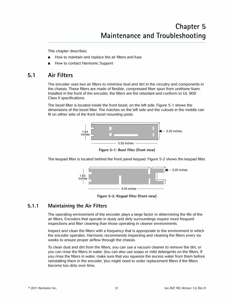
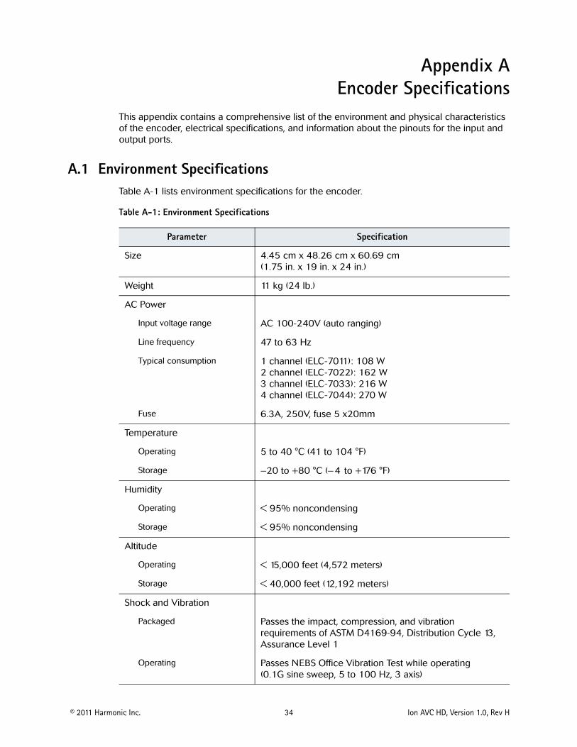
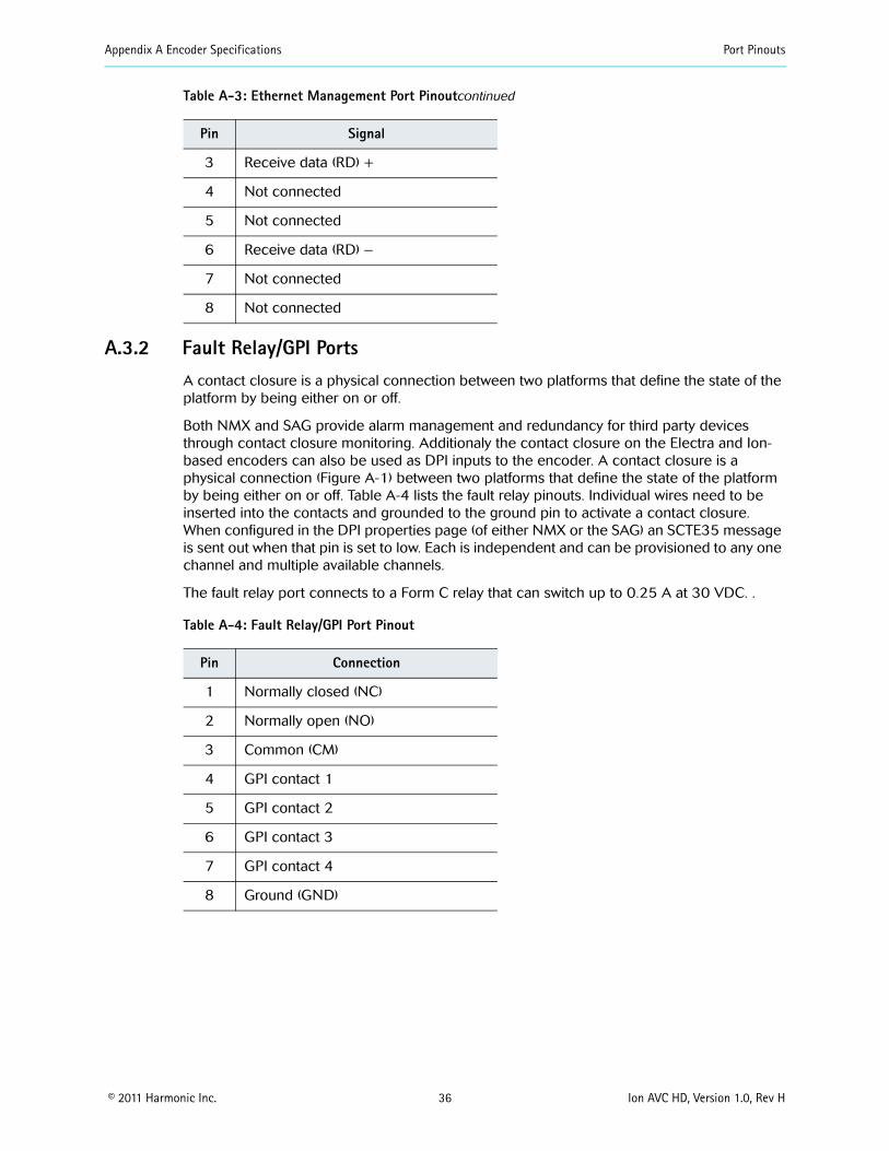
Appendix A Encoder Specifications Port Pinouts
copy 2011 Harmonic Inc 36 Ion AVC HD Version 10 Rev H
A32 Fault RelayGPI Ports A contact closure is a physical connection between two platforms that define the state of the platform by being either on or off
Both NMX and SAG provide alarm management and redundancy for third party devices through contact closure monitoring Additionaly the contact closure on the Electra and Ion-based encoders can also be used as DPI inputs to the encoder A contact closure is a physical connection (Figure A-1) between two platforms that define the state of the platform by being either on or off Table A-4 lists the fault relay pinouts Individual wires need to be inserted into the contacts and grounded to the ground pin to activate a contact closure When configured in the DPI properties page (of either NMX or the SAG) an SCTE35 message is sent out when that pin is set to low Each is independent and can be provisioned to any one channel and multiple available channels
The fault relay port connects to a Form C relay that can switch up to 025 A at 30 VDC
Table A-4 Fault RelayGPI Port Pinout
Pin Connection
1 Normally closed (NC)
2 Normally open (NO)
3 Common (CM)
4 GPI contact 1
5 GPI contact 2
6 GPI contact 3
7 GPI contact 4
8 Ground (GND)
3 Receive data (RD) +
4 Not connected
5 Not connected
6 Receive data (RD) ndash
7 Not connected
8 Not connected
Table A-3 Ethernet Management Port Pinoutcontinued
Pin Signal
Appendix A Encoder Specifications Port Pinouts
copy 2011 Harmonic Inc 37 Ion AVC HD Version 10 Rev H
Figure A-1 Fault RelayGPI Ports
copy 2011 Harmonic Inc 38 Ion AVC HD Version 10 Rev H
Appendix BAudio and Video Specifications
B1 AIC FeaturesThe AIC adapter accepts analog (balanced or unbalanced) discrete AES3SPDIF digital and AES3 embedded in serial digital video inputs For analog and discrete AES3 inputs sampling frequencies of 48 kHz 441 kHz and 32 kHz are supported Embedded digital is supported only for 48 kHz sampling which must be synchronous to the video
Table B-1 lists the AIC features for each coding mode including the supported sampling frequencies and ES bit rates
Table B-1 AIC Features
AIC Feature Coding Mode SamplingFrequency
ES Bit RatesSupported (Kbps)
MPEG-1 Layer II compression
Single channel (10) 32 kHz 441 kHz 48 kHz
32 48 56 64 80 96 112 128 160 192
Dual channel (1+1) Stereo channel (20) Joint stereo channel
32 kHz 441 kHz 48 kHz
64 96 112 128 160 192 224 256 320 384
MPEG-1 Layer II compression SPPC (separate PID per channel)
Single channel (10) 32 kHz 441 kHz 48 kHz
32 48 56 64 80 96 112 128 160 192
Dolby Digital (AC-3) compression
Single channel (10) 32 kHz 441 kHz 48 kHz
56 64 80 96 112 128 160 192 224 256 320
384 448a 512a 576a
640a
Stereo channel (20) 32 kHz 441 kHz 48 kHz
96 112 128 160 192
224 256 320 384 448a
512a 576a 640a
Dolby Digital (AC-3) passthrough
Up to 51 channels (32+LFE professional 16-bit mode)
32 kHz441 kHz48 kHz
56b 80b 96 112 128 160 192 224 256 320 384
448a 512a 576a 640a
Up to 51 channels (32+LFE professional 32-bit mode)
32 kHz441 kHz48 kHz
256 320 384 448a 512a
576a 640a
Appendix B Audio and Video Specifications AIC Features
copy 2011 Harmonic Inc 39 Ion AVC HD Version 10 Rev H
Note the following limitations
ATSC Standard A53 specifies that only 48 kHz sampling may be used and that ES bit rates must be less than or equal to 384 Kbps for a complete service It also specifies that a two-channel dialog-only service must be less than or equal to 192 Kbps Total ES rates for all services must be less than or equal to 512 Kbps
Embedded audio must be 48 kHz sampling and synchronous with the video See SMPTE 272M for definitions
MPEG AAC and HE AAC can be placed into the output Transport Stream encapsulated in either of two methods
ADTS
ADTS is an acronym for ldquoAudio Data Transport Streamrdquo This is the default used if the user selects MPEG-2 AACHE AAC ADTS is assigned a stream type value of 0x0F
LATMLOAS
LATM is an acronym for rdquoLow Overhead Audio Transport Multiplexrdquo LOAS is an acronym for rdquoLow Overhead Audio Streamrdquo and furnishes an outer wrapper for LATMs inner wrapper of the raw audio Elementary Stream syntax MPEG-4 AAC and HE AAC bitstreams are encapsulated as LATMLOAS and assigned a stream type value of 0x11
Encapsulation mode is controlled by selecting rdquoMPEG-2rdquo or rdquoMPEG-4rdquo as required
MPEG HE AAC compression
Single channel (10) 32 kHz441 kHz48 kHz
32 48 56 64 96
Dual channel (1+1) Stereo channel (20) Joint stereo channel
32 kHz441 kHz48 kHz
32 48 56 64 96 112 128
MPEG AAC compression
Single channel (10) 32 kHz441 kHz48 kHz
32 48 56 64 96 112 128 182 192
Dual channel (1+1) Stereo channel (20) Joint stereo channel
32 kHz441 kHz48 kHz
64 96 112 128 182 192 224 256 320 384
a These rates are not compliant with A53b These rates are valid for 10 coding only
Table B-1 AIC Features continued
AIC Feature Coding Mode SamplingFrequency
ES Bit RatesSupported (Kbps)
Appendix B Audio and Video Specifications Dolby Digital (AC-3) Audio
copy 2011 Harmonic Inc 40 Ion AVC HD Version 10 Rev H
B2 Dolby Digital (AC-3) Audio The Ion AVC HD supports Dolby Digital (AC-3) native audio encoding AIC-equipped encoders support native two-channel Dolby Digital (AC-3) compression AIC-equipped encoders also support Dolby Digital (AC-3) 51 in passthrough mode
NOTE Harmonic supports Dolby Digital (AC-3) passthrough rates of 96 to 640 Kbps and native Dolby Digital (AC-3) rates of 56 to 640 Kbps
Table B-2 lists the bit rates for the sample frequencies of 48 kHz 441 kHz and 32 kHz
Table B-2 Dolby Digital (AC-3) Audio Bit Rates
Audio Bit Rate (Kbps)
Audio without PCR Audio with PCR
48 kHz 441 kHz 32 kHz 48 kHz 441 kHz 32 kHz
56 658 605 627 658 605 627
64 752 691 689 752 691 689
80 846 864 877 846 864 877
96 1034 1036 1003 1034 1036 1065
112 1222 1209 1191 1222 1209 1191
128 1316 1382 1316 1410 1382 1379
160 1692 1641 1692 1692 1727 1692
192 1974 1986 2005 2068 1986 2005
224 2350 2332 2319 2350 2332 2319
256 2632 2677 2632 2726 2677 2695
320 3290 3282 3321 3384 3368 3321
384 3948 3973 3948 4042 3973 3948
448 4606 4664 4637 4606 4664 4637
512 5264 5268 5264 5264 5268 5264
576 5922 5959 5891 5922 5959 5953
640 6580 6564 6580 6580 6564 6580
NOTE Changing from non-single-channel mode to single-channel mode provisions the transport bit rate automatically
When you change between single-channel and non-single-channel modes the encoder automatically provisions the bit rate to the closest available bit rate In some cases this means the bit rate is lower because provisioning does not increase the bit rate defined for the port Therefore changing the coding mode from non-single-channel mode to any of the four highest bit rates causes the encoder to provision the bit rate to 192 Kbps
Appendix B Audio and Video Specifications Video Specifications
copy 2011 Harmonic Inc 41 Ion AVC HD Version 10 Rev H
In the case of the three lowest bit rates when you change from single-channel to non-single-channel mode because the bit rate is the lowest available the encoder provisions to the next highest available bit rate 64 Kbps If you set the bit rate to 80 Kbps and then change the coding mode to non-single-channel the encoder provisions the bit rate to 64 Kbps
B3 Video Specifications The encoder is equipped to handle high definition (HD) serial digital input (SDI)
Table 5-1 Video Specifications
Feature Specification Comments
Input formats Serial digital component High definition serial digital interface (HD-SDI) per SMPTE 292M
VITC support 1080i 30MB 720p 60MB
Import formats supported in HD
B4 VITC SupportThe Ion AVC HD supports extraction of Vertical Interval Time Code (VITC) data placed into VANC or HANC per SMPTE RP188 The VITC data is used to synchonize DPI events on hoth HD and SD encoders HD encoders receive VITC input carried in the Vertical Ancillary data space (VANC) or Horizontal Ancillary data space (HANC) of a 292MB stream
copy 2011 Harmonic Inc 42 Ion AVC HD Version 10 Rev H
Appendix CEncoder Back Panel Slot Locations
C1 Adapter Configurations for All EncodersFigure C-1 represents the back panel of an encoder Table C-1 shows the slot number and the modules that can be installed in encoders that are not associated with a FLEX module Table C-2 shows the slot number and the modules associated with the FLEX module that can be installed NMX uses the slot number to differentiate between adapters of the same type within the encoder
Slot 2
Slot 1 Slot 3
Slot 4 FLEX
Main Board
Slot 5 FLEX
Figure C-1 Slot numbers
Table C-1 shows the adaptersmodules software support and configuration recommendations for non-FLEX based encoders
Table C-1 Supported adaptersmodules and configuration recommendations for this encoder
Adapter Slot Notes
AIC Any slot (1-5 adapters per chassis)
AHC-RAC Any slot (1-5 adapters per chassis)
AHC-561 Slots 1- 4 (1-4 adapters per chassis) Not supported on slot 5 Supported only via NMX
ASI Output Slot 5 without a FLEX module Slot 2 with a FLEX module (1 adapter per chassis)
Only the first two ports are active and are electrical duplicates of each other
AB Power Input switch
Slots 1 and 3 (both)
C11 Additional Adapter Configurations for FLEX-based EncodersTable C-2 lists the adapter configurations available for FLEX-based encoders
Table C-2 FLEX Module Options (for use with FLEX module)
Card Option Notes
FLEX Slot 4 must be populated first slot 5 second (1-2 adapters per chassis)
Requires CPC revision 105 or higher see Viewing the Control Board (CPC) Revision Information on page 43
GbE Slot 1 only (1 adapter per chassis)
Used with FLEX module for input only
Appendix C Encoder Back Panel Slot Locations Adapter Configurations for All Encoders
copy 2011 Harmonic Inc 43 Ion AVC HD Version 10 Rev H
NOTE ASI Input adapters (used with FLEX module) and ASI Output adapters utilize the same hardware but perform different functions based on 1) the slot number and 2) if a FLEX module is installed If installed in slots 2 or 5 the ASI adapter is always an output If a FLEX module is installed an ASI adapter installed in slots 1 or 3 is an input
C12 Viewing the Control Board (CPC) Revision Information1 From the Platform tab click on the Platform link
2 Click on the Control Board (CPC) link
The Control Board (CPC) Configuration page appears
Click on the Maintenance tab to examine the version information
ASI Input Slot 1 (typical) slot 3 if slot 1 isalready in use (1 card perchassis) For FLEX only chassisthe FLEX module goes into slot4 and 5 Slot 4 must bepopulated first For baseband andcompressed mixed inputencoders the FLEX module canbe either slot 4 or 5 ASI inputadapters cannot use slot 4 as itis used for first FLEX module
ASI input is currently only forFLEX module ASI in slots 1 3and 4 appears as an input card
RF 8VSB Slot 1 (typical) or slot 3 if slot 1 is already in use or slot 2 if slots 1 and 3 are already in use (1 adapter per chassis)
Used with FLEX module for input only
Table C-2 FLEX Module Options (for use with FLEX module)
Card Option Notes
copy 2011 Harmonic Inc 44 Ion AVC HD Version 10 Rev H
Appendix DBoot Sequence
This appendix describes the encoder boot sequence including the messages that appear on the local control panel display
D1 Local Control Panel Display Messages during BootupMessages on the local control panel indicate progress during boot-up During a successful boot many events occur so quickly you cannot see the messages The following sections describe the messages that you can see during boot attempts
NOTE During the boot sequence do not press any key on the keypad
The following sequence describes the display on the vacuum fluorescent display (VFD) during a successful startup
Power on
VFD line 1 = Harmonic Inc VFD line 2 = System Loading
Begin loading
VFD line 1 = Divicom Ion AVC HD VFD line 2 = System Loading
Booting
VFD line 1 = Divicom Ion AVC HD VFD line 2 = Loading xxxxxxxxelf
Finished
VFD line 1 = Divicom Ion AVC HD VFD line 2 = Multichannel Encoder
D2 Other Local Control Panel Display MessagesThe local control panel displays messages for other types of restarts including a system reset and loading new software
D21 Resetting the Encoder When you reset the encoder from NMX a message on the VFD shows that the encoder has been reset The encoder uses the boot file on the hard drive when you reset it
Reset from NMX
VFD line 1 = Bye bye VFD line 2 =
After power cycle
VFD line 1 = Harmonic Inc VFD line 2 = System Loading
Begin loading
Appendix D Boot Sequence Other Local Control Panel Display Messages
copy 2011 Harmonic Inc 45 Ion AVC HD Version 10 Rev H
VFD line 1 = Divicom Ion AVC HD VFD line 2 = System Loading
Booting
VFD line 1 = Divicom Ion AVC HD VFD line 2 = Loading xxxxxxxxelf
Finished
VFD line 1 = Divicom Ion AVC HD VFD line 2 = Multichannel Encoder
D22 Loading New Software You can download new software to an encoder using NMX After downloading the software restart the encoder to begin using the new software The following messages appear
Begin loading
VFD line 1 = Divicom Ion AVC HD VFD line 2 = System Loading
Booting
VFD line 1 =Divicom Ion AVC HD VFD line 2 = Loading xxxxxxxxelf
Finished
VFD line 1 = Divicom Ion AVC HD VFD line 2 = Multichannel Encoder
copy 2011 Harmonic Inc 46 Ion AVC HD Version 10 Rev H
Appendix EWiring the ndash48 VDC Power Supply
If your encoder has the optional ndash48 VDC power supply follow these steps to wire the power supply
E1 Getting StartedBefore you begin wiring the ndash48 VDC power supply make sure that you provide the necessary overcurrent protection wires and power connector
E2 Power Source SpecificationsThe DC power source feeding the encoder must meet the following requirements
Electrically isolated from any AC power source
Positive ground The Positive bus of the DC power source must be reliably connected to the Ground bus
Each feed-pair must provide a continuous supply of power that meets the following specifications
Table E-1 Power Source Specifications
Parameter Specification
Voltage 40ndash60 VDC
Max operating current 8 amps
Max input surge current
20 amps
E3 Overcurrent ProtectionTo provide overcurrent protection
Provide overcurrent protection devices as part of each rack housing encoders
Locate a readily accessible disconnect device between the DC power source and the encoder
Use a 10-amp double-pole fast trip DC-rated disconnect device for each DC power connector
NOTE Overcurrent protection devices must meet applicable national and local electrical safety codes and be approved for the intended application
E4 Wiring RequirementsThe encoder is connected to the DC power source using three wires
ndashVin
GND
Appendix E Wiring the ndash48 VDC Power Supply Power Connector
copy 2011 Harmonic Inc 47 Ion AVC HD Version 10 Rev H
+Vin
Although Harmonic provides the power input connector with the encoder you must supply the wires
The wires to be used must comply with the following specifications
Table E-2 Recommended Wire Specifications
Parameter Specification
Suitable conductor material Copper only
ndashVin and +Vin wires 16 AWG rating
Ground cable 16 AWG rating
Cable insulation rating Minimum 80 C low smoke fume (LSF) flame retardant
Cable type Must comply with at least one of the following standards
Branch circuit cable insulation color
Per applicable national electrical codes
E5 Power ConnectorThe encoder is supplied with a special DC power connector plug that matches the DC power socket on the back of the encoder
This connector is made by WAGO model number 231-103037-000
Use only the original connector for connecting the encoder to the DC power source Contact Harmonic Technical Support if you want to use any other type of connector
The following figure shows the connector and its strain relief housing
Figure E-1 CableStrain Relief Housing
E6 Assembling the DC Input Power CableTo assemble the DC input power cable
1 Prepare the power wires as specified in E4 Wiring Requirements on page 46
2 Use the disconnect device to make sure that the power supply from the DC power source to the cables is switched off
UL 1581 (VW-1) - UL style 1028 or equivalent EEE 383 EEE 1202-1991
Appendix E Wiring the ndash48 VDC Power Supply Assembling the DC Input Power Cable
copy 2011 Harmonic Inc 48 Ion AVC HD Version 10 Rev H
CAUTION Turn off the power before proceeding with these instructions
3 Unplug the WAGO power connector from the power socket on the encoder back panel
4 Identify the three wires coming from the DC power source that are used in the connection to the expansion unit
ndashVin
+Vin
GND
5 Strip up to 03 inches (8 mm) of insulation from each of the wires coming from the DC power source
Do not strip more than this length from each wire Stripping more leaves uninsulated wire exposed outside the DC connector after the assembly is complete
6 Insert a small screwdriver into the rectangular hole directly above the hole in the DC connector where you want to insert the first cable and press down on the screwdriver
This opens the cage clamp for this section of the DC plug connector
NOTE WAGO also sells tools specifically designed to open cage clamps easily For more information either visit the WAGO web site at wwwwagocom or call WAGO at 1-800-346-7245 and request information about items 210-250 or 231-131
7 Feed the exposed section of the wire into the matching hole in the DC plug connector
See the pin-out figure below to match wires with the required holes
Figure E-2 Pin Out Specification
8 Repeat steps 5 through 7 for the other two wires to complete the assembly of the DC input cable
NOTE If you need to remove a wire from the DC plug connector insert a small screwdriver into the slot directly above the wire and press down on the screwdriver to free the wire from the cage clamp
copy 2011 Harmonic Inc 49 Ion AVC HD Version 10 Rev H
Appendix FDiviComtrade FLEX Decoding Module
F1 IntroductionThe DiviCom FLEX decoding module delivers video decoding capability and is integrated into either an Electra or Ion encoder chassis (which will be referred to as the ldquohostrdquo encoder) The FLEX decoding module (hereafter referred to as the FLEX module) is a decoding module only (see Figure F-1) A single FLEX module is able to decode up to two (2) incoming channels and an appropriately configured encoder can deliver up to four (4) channels in a single rack-unit (1-RU) The FLEX module decodes MPEG-2 in both standard definition (SD) or high definition (HD) formats thereby eliminating the dependency on ingress formats The FLEX module is a unique gateway designed with the flexibility to deliver any type of pre-compressed video to any host encoder The FLEX module supports both ASI and IP inputs the most efficient interfaces used to route and transport pre-compressed video feeds
NOTE AHC-561 card is not supported for use with FLEX modules
The FLEX module is controlled and configured with the NMX Digital Service Manager application or the Configuration Manager the Web-based GUI The FLEX module also accepts decoded ATSC 8VSB signals from the DiviCom RF Input Card ( DiviComtrade RF Input Adapter on page 74) The FLEX module does not descramble or reconstruct all audio and ancillary data services (such as VBI) on the output port
NOTE The encoder chassis configuration must include an input module for IP The same GbE Pro card are used for both ProStream 1000 muxes and Electra encoders
Figure F-1 FLEX Module Ports
F2 Video Decoding Specifications Table F-1 describes video specifications supported by the Table F-1describes video specifications supported by the FLEX module See the following tables for more information about video and audio compression See the following tables for more information about video and audio compression
Table F-1 Video Decoding Features
Feature Support
Video Decoding MPEG-2 MPML MPEG-2 MPHL
Aspect Ratios 43 and 169
Appendix F DiviComtrade FLEX Decoding Module Audio Passthrough Specifications
copy 2011 Harmonic Inc 50 Ion AVC HD Version 10 Rev H
F3 Audio Passthrough SpecificationsTable F-2 describes the audio passthrough specifications supported by the FLEX module
Table F-2 Audio Passthrough Specifications
Feature Support
Number of channels
Audio formats
Audio processing
Operating modes
Video Formats 480i2997 576i25 720p5994 72050 1080i25 1080i2997
Additional features (available on some specific hosts only)
General HD decode and downcovert to SDSD hosts only Decodes MPEG-2 MPML (480i and 576i)HD hosts only Decodes MPEG-2 MPHL (720p 5060 and 1080i
5060)Specific hosts only ASI input and output available with FLEX module (using
two ASI cards)
8 (however the total passthrough bitrate per FLEX program cannot exceed 4Mbps)
MPEG-1 Layer II Dolby Digital (AC-3) and AAC audio passthrough
MPEG-1 Layer II10 and 20 decode Dolby AC-3 51 and 20 decode
Audio passthrough Audio passthrough of dual channel No Fixed Audio Gain Adjustment for passthrough audio Audio passthrough with repacketization Audio passthrough Silence insertion during CRC errors or buffer underruns
Mono dual channel or decode to stereo joint stereo 51 multichannel (no decode to PCM on audio passthrough)
Table F-1 Video Decoding Features
Feature Support
Appendix F DiviComtrade FLEX Decoding Module Audio Decode Specifications
copy 2011 Harmonic Inc 51 Ion AVC HD Version 10 Rev H
F4 Audio Decode SpecificationsTable F-3 describes the audio decode specifications supported by the FLEX module
Table F-3 FLEX Audio Decode Specifications
Feature Support
Audio Decoding
Decoding Mode
Audio Formats (MPEG-1 Layer II AC-3)
Compression Mode
Additional Support
NOTE Audio leveling is also supported by the FLEX decoding module This feature defines a constant gain adjustment for incoming audio signal
F41 Decoding Resource ConsiderationsA multichannel decode stream counts as 3 stereo decode streams If no downmixing and no dynamic level adjustment is enabled on any stream the absolute maximum number of audio decode streams is 8 allowed in one of these (and only these) combinations
Up to 4 monostereo decode streams per FLEX decoding port
Up to one multichannel audio decode and one stereo decode stream per FLEX decoding port
Up to 2 multichannel audio decode and 2 stereo audio decode streams on the first FLEX decoding port
Up to 8 monostereo decode streams on the first FLEX decoding port (with no audio on second port)
See Table F-4 on page 52 for information on AC-3 resource considerations
Static Level Adjustment Dynamic Level Adjustment
Dolby AC-3 with multichannel decoding and downmixing
Dolby AC-3 Mono and Stereo decoding
Mono and stereo (20)
(AC-3) Line mode and RF line mode
Support for multiple deocde of the same PID (audio decode)
Table F-4 AC-3 Resource Considerations
Input Format Audio Input (into card) Decoding Mode
Multichannel DownMix checkbox
Result
Resource Usage
Equivalent
AC-3
Mono
Mono Available Audio on the left channel Silence on the right channel
Stereoa
Stereo Audio on both channels
3 x Stereo
Multichannel No Audio on the Center channel Silence on all others
3 x Stereo
Stereo
Mon Available (irrelevant for this decoding mode)
Audio on the left channel Silence on the right channel
Stereoa
Stereo Audio on both channels
Multichannel No Audio on both left and right channels Silence on all others
3 x Stereo
AC-3 (continued)
Multichannel
Mono Available (must be enabled for this decoding mode or an alarm is raised and decoding stops)
Multichannel downmix to Mono on the left channel
Stereoa
Stereo Audio on both channels
Multichannel No Audio on both left and right channels Silence on all others
3 x Stereo
Appendix F DiviComtrade FLEX Decoding Module Audio Decode Specifications
copy 2011 Harmonic Inc 52 Ion AVC HD Version 10 Rev H
Appendix F DiviComtrade FLEX Decoding Module Ancillary Data Specifications
copy 2011 Harmonic Inc 53 Ion AVC HD Version 10 Rev H
See Table F-5 on page 53 for information on MPEG-L2 resource considerations
Table F-5 MPEG-L2 Resource Considerations
Input Format Audio Input (into card)
Decoding Mode Result Resource Usage
Equivalent
MPEG-L2
Mono Mono Audio on left channel Silence on right channel StereoStereo
Stereo Mono Audio on both channels
Stereo
F5 Ancillary Data SpecificationsA multichannel encoder equipped with FLEX is essentially receiving and outputting compressed streams Therefore the terminology used regarding ancillary data can be incorrect or misleading VBI data is not applicable to fully digital signals but is used by user habit The FLEX module does not re-create any of the ancillary data it simply passes it intact as packets of bits to the associate encoderrsquos TS output
Table F-6 describes the ancillary data specifications supported by the FLEX module
Table F-6 Ancillary Data Specifications
Feature Support
Vertical Interval Data Services (Pass through only)
WST (Teletext) Inverted WST WSS VPS AFD and bar data VITC Closed Captioning per CEA-608 and 708 AMOL and TV Guide data
Number of channels 4 PIDS
F6 Input SpecificationsTable F-7 describes the input specifications supported by the FLEX module
a Enabling Multichannel downmixing allocates resources for downmixing resulting in resource usage equivalent to 3 x Stereo
Table F-7 Input Specifications
Feature Support
Transport stream Inputs MPEG-2 TS
ASI interface (optional module)
Connector 4x BNC 75 Ω
MPEG format 188 Bytes per TS packet
Appendix F DiviComtrade FLEX Decoding Module Output Specifications
copy 2011 Harmonic Inc 54 Ion AVC HD Version 10 Rev H
F7 Output SpecificationsTable F-8 describes the output specifications supported by the FLEX module
Table F-8 Outputs Specifications
Feature Support
Video Outputs
Connector Type
Embedded Data along the Video
F8 Environmental and Physical Compliant with ROHS Directive 200295EC Refer to the encoder environmental specifications for additional information
Processing 1 MPTSSPTS per port Up to 150 Mbps per port
ASI Ports 4
IP interface (optional module)
Type Gigabit Ethernet
IP ports 2 Independent ports
Connector 2 x copper SFPs
Speed 1 x 1000 Mbps per port
IP encapsulation MPEG-2 TS over UDPIP 1 to 7 TS IP
MPEG format 188 Bytes per TS packet
MPEG-2 TS MPTS and SPTS
Maximum Bit-Rate per Socket
80 Mbps
Addressing Unicast and multicast
Management IGMP ARP and ICMP
Forward Error Correction (FEC)
The FLEX module supports SMTE 2022 Annex C forward error correction (FEC) FEC provides lost packet recovery at the receiving devices
RF Input Card
For specifics see Appendix G on page 74
One (1) per decoded channel with video only SDI or HD-SDI One (1) additional per channel for confidence monitoring only
DIN 1023 (DIN 1023 to BNC adapters available)
No Audio VBI VANC or HANC data embedded The data are embedded into the SDIHD-SDI output
Table F-7 Input Specifications
Feature Support
Appendix F DiviComtrade FLEX Decoding Module Module Slots
copy 2011 Harmonic Inc 55 Ion AVC HD Version 10 Rev H
F9 Module SlotsThe diagram below represents the back panel of typical encoder The diagram shows the slot number and the modules that can be installed in that slot NMX or Configuration Manager uses the slot number to differentiate between cards of the same type within the encoder
Slot 2
Slot 1 Slot 3
Slot 4 FLEX
Main Board
Slot 5 FLEX
F10 Installing the FLEX Decoding ModuleThis section describes how to install the FLEX Decoding Module The modulersquos ports are shown in Figure F-1 on page 49
Host encoders encoders are typically ordered from the factory with the FLEX module already installed However if additional FLEX modules are installed installation of the FLEX module in the field would be required
F1001 ESD Safety Precautions
To protect modules from electrostatic discharge (ESD) follow these safety precautions
Always wear a properly grounded antistatic wrist strap whenever handling the modules
Keep the module inside the antistatic bag until you are ready to install the module in a chassis
F101 Installing a ModuleBefore installing the FLEX module you may need to upgrade the software version on the encoder Contact Harmonic Customer Support to find out which software version you need to install the additional module
There is also a CPC limitation that requires version 105
NOTE Before making changes to the FLEX module make sure the service configuration is cleared before powering down the system Also before installing the FLEX module make sure that the encoder has the appropriate software version installed before installing the module using either NMX or the Configuration Manager
NOTE The FLEX module must be installed in slot 4 (and an optional second module in slot 5) of the encoder
You need a Phillipstrade screwdriver to install the FLEX module
To install the FLEX module
1 Turn off the encoder in which you are installing the module
2 Remove the protective covers from slots 1 through 5 where you are going to install the module (by loosening the two screws with the Phillips screwdriver)
Save the cover for future use
3 While wearing an ESD wrist strap unpack the module from its antistatic protective packing material
Appendix F DiviComtrade FLEX Decoding Module Cabling the FLEX Module
copy 2011 Harmonic Inc 56 Ion AVC HD Version 10 Rev H
CAUTION Unpack and handle the module away from electric motors transformers and other similar machinery
4 Slide the module onto the encoder by lining up the edges of the module with the slots in the chassis
Make sure that the FLEX module goes into the encoder smoothly without binding or scraping other modules The modules should slide easily until you feel the module engage the internal connector and the module is flush with the back of the encoder Do not force the module
5 Tighten the two screws with the screwdriver
NOTE Refer to the encoder guide or online help for information about accommodating the new FLEX module in the encoderrsquos configuration
F11 Cabling the FLEX ModuleThis section describes how to cable the FLEX module Cabling the FLEX module is very straight forward All video and monitor ports are clearly marked The following table lists the ports and required connectors
NOTE Video ports can either be used for loopback or confidence monitoring
Each firmware license ships with two video loopback cables An optional adapter cable can be purchased for use with the monitoring ports You must also have an IP input module installed Figure F-3 on page 57 provides additional information on understanding the encoderrsquos LED color values
F12 Re-Encode Chassis Scenarios This section describes two recommended re-encode chassis scenarios 2- Channel and 4-Channel scenarios
F121 2 - ChannelFigure F-1 on page 49 illustrates a typical 2-channel re-encode chassis cabling assignment This scenario makes use of a base 2-channel encoder chassis Table F-9 describes the port and cable associations
NOTE For the monitor ports there is a DIN to BNC pigtail connector that can be ordered Harmonic Part number FLEX-MON 229-0054067
Table F-9 Port and Cable Assignments (2-channel)
Port Description Connector
Video 1 75 Ω cable DIN 1023
Appendix F DiviComtrade FLEX Decoding Module Re-Encode Chassis Scenarios
copy 2011 Harmonic Inc 57 Ion AVC HD Version 10 Rev H
NOTE The FLEX module must use slot 4
Figure F-2 2 - Channel Re-Encode Chassis (Cable) Scenario
Figure F-3 describes the LED colors and what they represent
720p
Figure F-3 LED Color Chart
Monitor 1 75 Ω cable This output port is used for the loopback cable that feeds an encoder
DIN 1023
Video 2 75Ω cable DIN 1023
Monitor 2 75 Ω cable The second output port can be used as a monitoring and troubleshooting purposes
DIN 1023
IP Module
Audio Module
Audio Module
FLEX Module
Attaches to optional SDI monitor (video only)
Table F-9 Port and Cable Assignments (2-channel)
Appendix F DiviComtrade FLEX Decoding Module Configuring the FLEX Module in NMX
copy 2011 Harmonic Inc 58 Ion AVC HD Version 10 Rev H
F122 4 - ChannelFigure F-4 illustrates a typical 4-channel re-encode chassis cabling assignment This scenario makes use of a base 4-channel encoder chassis
Table F-10 Port and Cable Assignments
Port Description Connector
Video 1 75 Ω cable DIN 1023
Monitor 1 75 Ω cable This output port is used for the loopback cable that feeds an encoder
DIN 1023
Video 2 75Ω cable DIN 1023
Monitor 2 75 Ω cable The second output port can be used as a monitoring and troubleshooting purposes
DIN 1023
Video 3 75Ω cable DIN 1023
Video 4 75Ω cable DIN 1023
IP Module Audio Module
Attaches to optional SDI monitor
FLEX Module
Figure F-4 4 - Channel Re-Encode Chassis (Cable) Scenario
F13 Configuring the FLEX Module in NMXRefer to the NMX online help system for configuring a FLEX module for use in your NMX Digital Service Manager application
copy 2011 Harmonic Inc 59 Ion AVC HD Version 10 Rev H
Appendix GDivicomtrade RF Input Card
This Appendix contains specifications for the DiviCom RF Input card
The RF Input card is a four channel ATSC 8VSB receiver It receives four independent ATSC 8VSB signals on its inputs and outputs four MPEG-2 Transport Streams over the chassis internal bus to one or more FLEX decoding modules The RF Input card does not support analog demodulation
The RF Input card can be managed by either NMX or SAG Figure G-1 on page 59 shows a diagram of the rear panel
Figure G-1 RF Input card
The LED lights show status as shown in Table G-1 on page 59
Table G-1 LED status lights
Display Status
Off Port disabled
Blinking Yellow Loss of synch
Red Packet error rate (PER) threshold exceeded
Steady yellow SNR below threshold
Green Port Enabled no alarms
G1 RF SpecificationsThe RF specifications for the card are listed below
VSB Input 4 Type lsquoFrsquo connectors per IEC 60169-24
Tuning Range VHFUHF (Channels 2-59)
NOTE Tuning range is limited to Channels 2 to 59 by software per the FCCIndustry Canada decisions to release channels 60 to 69 for public safety use
Sensitivity --83 dBm6 MHz
Dynamic Range gt 80dB
Appendix G Divicomtrade RF Input Card Output Specifications
copy 2011 Harmonic Inc 60 Ion AVC HD Version 10 Rev H
G2 Output SpecificationsThe output specification for the card is
Four MPEG-2 Transport Streams per ATSC A53 Part 3 and ISOIEC 13818-1
G3 Environmental and Physical Compliant with ROHS Directive 200295EC Refer to the encoder environmental specifications for additional information
copy 2011 Harmonic Inc 61 Ion AVC HD Version 10 Rev H
Appendix HAB Power Switch
H1 IntroductionThis appendix contains specifications for the AB Power switch
The AB Power switch receives two separate AC main input sources (to support redundancy) monitors the voltage and selects the good voltage to provide one AC output for input into either the AC or DC power supply The AB Power switch automatically changes from the line A input to the Line B input (or the reverse) upon loss of power on the active line The AB Power switch uses and monitors the active line continuously and switches to the backup port only when the active line has a fault The card switches back automatically when the active port is detected as normal and stable (with an appropriate delay)
NOTE The AB Power switch is a dual-height card and can only be installed in slots 1 and 3
The AB Power switch can be managed by SAG Figure H-1 shows a illustration of the AB Power switch
Pigtail power output cable(plugs into encoder)
Figure H-1 AB Power switch
Appendix H AB Power Switch Card Status
copy 2011 Harmonic Inc 62 Ion AVC HD Version 10 Rev H
H2 Card StatusThis section describes how to recognize the current status of the AB Power switch through its LEDs
NOTE It is recommended that you use A for primary equipment and B for backup equipment
The LED lights show card status as shown in Table H-1 on page 62
Table H-1 LED status lights
Display Status
Red Input power (for that port) is not within the acceptable voltage range
Green Steady input power for that port is within acceptable voltage rangeFlashing port is being utilized for input power
Orange Port failure (canrsquot be used)
Off No power or broken LED
copy 2011 Harmonic Inc 63 Ion AVC HD Version 10 Rev H
AAC power supply
connecting 25overview 17
agency approvals 4air filters 31 to 32airflow 21alphanumeric keys 27audio cables connecting 24audio compression rates described 40audio encoding features 13
Bback panel
described 16Ethernet management port 18 35fault relay port 18fuse 17IP output port 18LEDs 18port specifications 35serial data port 18video input ports 17
boot sequence 44
Ccabling the encoder 24compliance and approval 2connecting
audio input cables 24DC power supply 46Ethernet management cable 25IP output cables 25video input cables 25
connections FCC compliance 2connectors
AC power 17Ethernet 18 35fault relay 36IP output 18RJ-45 18 35video 35
cTUVus North American safety approval 4
DDC power supply 46digital program insertion 14display front panel 28Dolby Digital AC-3 bit rates 40DPI 14
Eenvironmental specifications 34Ethernet management port
connecting cable 25described 18specifications 35
European EMIEMC approvals 4
Ffault relay port 18 36FCC compliance 2features
audio encoding 13general 10video encoding 12
filters See air filters 31front bezel 15
removing 23front panel 15 27front panel display 28function keys 27fuse 32
Hhardware specifications 34Harmonic equipment modifying 2Harmonic Heartbeat Protocol 14help displaying on VFD 28HHP 14hot keys 27
Iinstalling the encoder 20IP output port
connecting cables 25described 18
Kkeypad 27
LLEDs
audio port 19back panel 18front panel 15video port 19
loading new software 45local control panel
described 15display 28
MMAC address viewing 29maintaining air filters 31maintaining fuse 32
Nnavigation keys 27North American EMI approvals 4North American Safety approvals 4
Ooutput port IP 18 25
Ppinouts port 35port specifications 35ports
Ethernet management 18
Index
Index
copy 2011 Harmonic Inc 64 Ion AVC HD Version 10 Rev H
fault relay 18IP output 18serial data 18video input 17
power supplyAC 25DC 46specifications 34
Rrack mounting 20rack rails attaching 22rack-mount kit 20replacing air filters 32resetting the encoder 44RJ-45 connectors 18 35
Sserial data port 18specifications
environment 34fuse 34hardware 34input and output 35port 35power supply 34video 41
standards and approvals 4
TTUV European safety approval 4
Uunpacking the encoder 20
VVFD
display during boot 44paths represented 28
video encoding features 12video input ports
connecting cables 25description 17LEDs 19
video specifications 41
WWEEE compliance 2
Harmonic Inc4300 North First StreetSan Jose CA 95134 USAT +1 408 542 2500 F +1 408 490 6708
wwwharmonicinccom
copy Copyright 2011 Manual Part No MAN-AVC-HD-INST-01
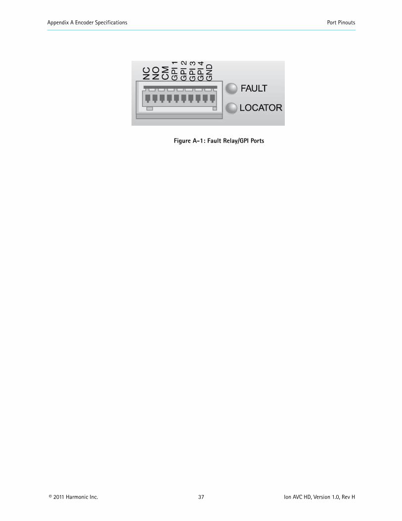
Appendix A Encoder Specifications Port Pinouts
copy 2011 Harmonic Inc 37 Ion AVC HD Version 10 Rev H
Figure A-1 Fault RelayGPI Ports
copy 2011 Harmonic Inc 38 Ion AVC HD Version 10 Rev H
Appendix BAudio and Video Specifications
B1 AIC FeaturesThe AIC adapter accepts analog (balanced or unbalanced) discrete AES3SPDIF digital and AES3 embedded in serial digital video inputs For analog and discrete AES3 inputs sampling frequencies of 48 kHz 441 kHz and 32 kHz are supported Embedded digital is supported only for 48 kHz sampling which must be synchronous to the video
Table B-1 lists the AIC features for each coding mode including the supported sampling frequencies and ES bit rates
Table B-1 AIC Features
AIC Feature Coding Mode SamplingFrequency
ES Bit RatesSupported (Kbps)
MPEG-1 Layer II compression
Single channel (10) 32 kHz 441 kHz 48 kHz
32 48 56 64 80 96 112 128 160 192
Dual channel (1+1) Stereo channel (20) Joint stereo channel
32 kHz 441 kHz 48 kHz
64 96 112 128 160 192 224 256 320 384
MPEG-1 Layer II compression SPPC (separate PID per channel)
Single channel (10) 32 kHz 441 kHz 48 kHz
32 48 56 64 80 96 112 128 160 192
Dolby Digital (AC-3) compression
Single channel (10) 32 kHz 441 kHz 48 kHz
56 64 80 96 112 128 160 192 224 256 320
384 448a 512a 576a
640a
Stereo channel (20) 32 kHz 441 kHz 48 kHz
96 112 128 160 192
224 256 320 384 448a
512a 576a 640a
Dolby Digital (AC-3) passthrough
Up to 51 channels (32+LFE professional 16-bit mode)
32 kHz441 kHz48 kHz
56b 80b 96 112 128 160 192 224 256 320 384
448a 512a 576a 640a
Up to 51 channels (32+LFE professional 32-bit mode)
32 kHz441 kHz48 kHz
256 320 384 448a 512a
576a 640a
Appendix B Audio and Video Specifications AIC Features
copy 2011 Harmonic Inc 39 Ion AVC HD Version 10 Rev H
Note the following limitations
ATSC Standard A53 specifies that only 48 kHz sampling may be used and that ES bit rates must be less than or equal to 384 Kbps for a complete service It also specifies that a two-channel dialog-only service must be less than or equal to 192 Kbps Total ES rates for all services must be less than or equal to 512 Kbps
Embedded audio must be 48 kHz sampling and synchronous with the video See SMPTE 272M for definitions
MPEG AAC and HE AAC can be placed into the output Transport Stream encapsulated in either of two methods
ADTS
ADTS is an acronym for ldquoAudio Data Transport Streamrdquo This is the default used if the user selects MPEG-2 AACHE AAC ADTS is assigned a stream type value of 0x0F
LATMLOAS
LATM is an acronym for rdquoLow Overhead Audio Transport Multiplexrdquo LOAS is an acronym for rdquoLow Overhead Audio Streamrdquo and furnishes an outer wrapper for LATMs inner wrapper of the raw audio Elementary Stream syntax MPEG-4 AAC and HE AAC bitstreams are encapsulated as LATMLOAS and assigned a stream type value of 0x11
Encapsulation mode is controlled by selecting rdquoMPEG-2rdquo or rdquoMPEG-4rdquo as required
MPEG HE AAC compression
Single channel (10) 32 kHz441 kHz48 kHz
32 48 56 64 96
Dual channel (1+1) Stereo channel (20) Joint stereo channel
32 kHz441 kHz48 kHz
32 48 56 64 96 112 128
MPEG AAC compression
Single channel (10) 32 kHz441 kHz48 kHz
32 48 56 64 96 112 128 182 192
Dual channel (1+1) Stereo channel (20) Joint stereo channel
32 kHz441 kHz48 kHz
64 96 112 128 182 192 224 256 320 384
a These rates are not compliant with A53b These rates are valid for 10 coding only
Table B-1 AIC Features continued
AIC Feature Coding Mode SamplingFrequency
ES Bit RatesSupported (Kbps)
Appendix B Audio and Video Specifications Dolby Digital (AC-3) Audio
copy 2011 Harmonic Inc 40 Ion AVC HD Version 10 Rev H
B2 Dolby Digital (AC-3) Audio The Ion AVC HD supports Dolby Digital (AC-3) native audio encoding AIC-equipped encoders support native two-channel Dolby Digital (AC-3) compression AIC-equipped encoders also support Dolby Digital (AC-3) 51 in passthrough mode
NOTE Harmonic supports Dolby Digital (AC-3) passthrough rates of 96 to 640 Kbps and native Dolby Digital (AC-3) rates of 56 to 640 Kbps
Table B-2 lists the bit rates for the sample frequencies of 48 kHz 441 kHz and 32 kHz
Table B-2 Dolby Digital (AC-3) Audio Bit Rates
Audio Bit Rate (Kbps)
Audio without PCR Audio with PCR
48 kHz 441 kHz 32 kHz 48 kHz 441 kHz 32 kHz
56 658 605 627 658 605 627
64 752 691 689 752 691 689
80 846 864 877 846 864 877
96 1034 1036 1003 1034 1036 1065
112 1222 1209 1191 1222 1209 1191
128 1316 1382 1316 1410 1382 1379
160 1692 1641 1692 1692 1727 1692
192 1974 1986 2005 2068 1986 2005
224 2350 2332 2319 2350 2332 2319
256 2632 2677 2632 2726 2677 2695
320 3290 3282 3321 3384 3368 3321
384 3948 3973 3948 4042 3973 3948
448 4606 4664 4637 4606 4664 4637
512 5264 5268 5264 5264 5268 5264
576 5922 5959 5891 5922 5959 5953
640 6580 6564 6580 6580 6564 6580
NOTE Changing from non-single-channel mode to single-channel mode provisions the transport bit rate automatically
When you change between single-channel and non-single-channel modes the encoder automatically provisions the bit rate to the closest available bit rate In some cases this means the bit rate is lower because provisioning does not increase the bit rate defined for the port Therefore changing the coding mode from non-single-channel mode to any of the four highest bit rates causes the encoder to provision the bit rate to 192 Kbps
Appendix B Audio and Video Specifications Video Specifications
copy 2011 Harmonic Inc 41 Ion AVC HD Version 10 Rev H
In the case of the three lowest bit rates when you change from single-channel to non-single-channel mode because the bit rate is the lowest available the encoder provisions to the next highest available bit rate 64 Kbps If you set the bit rate to 80 Kbps and then change the coding mode to non-single-channel the encoder provisions the bit rate to 64 Kbps
B3 Video Specifications The encoder is equipped to handle high definition (HD) serial digital input (SDI)
Table 5-1 Video Specifications
Feature Specification Comments
Input formats Serial digital component High definition serial digital interface (HD-SDI) per SMPTE 292M
VITC support 1080i 30MB 720p 60MB
Import formats supported in HD
B4 VITC SupportThe Ion AVC HD supports extraction of Vertical Interval Time Code (VITC) data placed into VANC or HANC per SMPTE RP188 The VITC data is used to synchonize DPI events on hoth HD and SD encoders HD encoders receive VITC input carried in the Vertical Ancillary data space (VANC) or Horizontal Ancillary data space (HANC) of a 292MB stream
copy 2011 Harmonic Inc 42 Ion AVC HD Version 10 Rev H
Appendix CEncoder Back Panel Slot Locations
C1 Adapter Configurations for All EncodersFigure C-1 represents the back panel of an encoder Table C-1 shows the slot number and the modules that can be installed in encoders that are not associated with a FLEX module Table C-2 shows the slot number and the modules associated with the FLEX module that can be installed NMX uses the slot number to differentiate between adapters of the same type within the encoder
Slot 2
Slot 1 Slot 3
Slot 4 FLEX
Main Board
Slot 5 FLEX
Figure C-1 Slot numbers
Table C-1 shows the adaptersmodules software support and configuration recommendations for non-FLEX based encoders
Table C-1 Supported adaptersmodules and configuration recommendations for this encoder
Adapter Slot Notes
AIC Any slot (1-5 adapters per chassis)
AHC-RAC Any slot (1-5 adapters per chassis)
AHC-561 Slots 1- 4 (1-4 adapters per chassis) Not supported on slot 5 Supported only via NMX
ASI Output Slot 5 without a FLEX module Slot 2 with a FLEX module (1 adapter per chassis)
Only the first two ports are active and are electrical duplicates of each other
AB Power Input switch
Slots 1 and 3 (both)
C11 Additional Adapter Configurations for FLEX-based EncodersTable C-2 lists the adapter configurations available for FLEX-based encoders
Table C-2 FLEX Module Options (for use with FLEX module)
Card Option Notes
FLEX Slot 4 must be populated first slot 5 second (1-2 adapters per chassis)
Requires CPC revision 105 or higher see Viewing the Control Board (CPC) Revision Information on page 43
GbE Slot 1 only (1 adapter per chassis)
Used with FLEX module for input only
Appendix C Encoder Back Panel Slot Locations Adapter Configurations for All Encoders
copy 2011 Harmonic Inc 43 Ion AVC HD Version 10 Rev H
NOTE ASI Input adapters (used with FLEX module) and ASI Output adapters utilize the same hardware but perform different functions based on 1) the slot number and 2) if a FLEX module is installed If installed in slots 2 or 5 the ASI adapter is always an output If a FLEX module is installed an ASI adapter installed in slots 1 or 3 is an input
C12 Viewing the Control Board (CPC) Revision Information1 From the Platform tab click on the Platform link
2 Click on the Control Board (CPC) link
The Control Board (CPC) Configuration page appears
Click on the Maintenance tab to examine the version information
ASI Input Slot 1 (typical) slot 3 if slot 1 isalready in use (1 card perchassis) For FLEX only chassisthe FLEX module goes into slot4 and 5 Slot 4 must bepopulated first For baseband andcompressed mixed inputencoders the FLEX module canbe either slot 4 or 5 ASI inputadapters cannot use slot 4 as itis used for first FLEX module
ASI input is currently only forFLEX module ASI in slots 1 3and 4 appears as an input card
RF 8VSB Slot 1 (typical) or slot 3 if slot 1 is already in use or slot 2 if slots 1 and 3 are already in use (1 adapter per chassis)
Used with FLEX module for input only
Table C-2 FLEX Module Options (for use with FLEX module)
Card Option Notes
copy 2011 Harmonic Inc 44 Ion AVC HD Version 10 Rev H
Appendix DBoot Sequence
This appendix describes the encoder boot sequence including the messages that appear on the local control panel display
D1 Local Control Panel Display Messages during BootupMessages on the local control panel indicate progress during boot-up During a successful boot many events occur so quickly you cannot see the messages The following sections describe the messages that you can see during boot attempts
NOTE During the boot sequence do not press any key on the keypad
The following sequence describes the display on the vacuum fluorescent display (VFD) during a successful startup
Power on
VFD line 1 = Harmonic Inc VFD line 2 = System Loading
Begin loading
VFD line 1 = Divicom Ion AVC HD VFD line 2 = System Loading
Booting
VFD line 1 = Divicom Ion AVC HD VFD line 2 = Loading xxxxxxxxelf
Finished
VFD line 1 = Divicom Ion AVC HD VFD line 2 = Multichannel Encoder
D2 Other Local Control Panel Display MessagesThe local control panel displays messages for other types of restarts including a system reset and loading new software
D21 Resetting the Encoder When you reset the encoder from NMX a message on the VFD shows that the encoder has been reset The encoder uses the boot file on the hard drive when you reset it
Reset from NMX
VFD line 1 = Bye bye VFD line 2 =
After power cycle
VFD line 1 = Harmonic Inc VFD line 2 = System Loading
Begin loading
Appendix D Boot Sequence Other Local Control Panel Display Messages
copy 2011 Harmonic Inc 45 Ion AVC HD Version 10 Rev H
VFD line 1 = Divicom Ion AVC HD VFD line 2 = System Loading
Booting
VFD line 1 = Divicom Ion AVC HD VFD line 2 = Loading xxxxxxxxelf
Finished
VFD line 1 = Divicom Ion AVC HD VFD line 2 = Multichannel Encoder
D22 Loading New Software You can download new software to an encoder using NMX After downloading the software restart the encoder to begin using the new software The following messages appear
Begin loading
VFD line 1 = Divicom Ion AVC HD VFD line 2 = System Loading
Booting
VFD line 1 =Divicom Ion AVC HD VFD line 2 = Loading xxxxxxxxelf
Finished
VFD line 1 = Divicom Ion AVC HD VFD line 2 = Multichannel Encoder
copy 2011 Harmonic Inc 46 Ion AVC HD Version 10 Rev H
Appendix EWiring the ndash48 VDC Power Supply
If your encoder has the optional ndash48 VDC power supply follow these steps to wire the power supply
E1 Getting StartedBefore you begin wiring the ndash48 VDC power supply make sure that you provide the necessary overcurrent protection wires and power connector
E2 Power Source SpecificationsThe DC power source feeding the encoder must meet the following requirements
Electrically isolated from any AC power source
Positive ground The Positive bus of the DC power source must be reliably connected to the Ground bus
Each feed-pair must provide a continuous supply of power that meets the following specifications
Table E-1 Power Source Specifications
Parameter Specification
Voltage 40ndash60 VDC
Max operating current 8 amps
Max input surge current
20 amps
E3 Overcurrent ProtectionTo provide overcurrent protection
Provide overcurrent protection devices as part of each rack housing encoders
Locate a readily accessible disconnect device between the DC power source and the encoder
Use a 10-amp double-pole fast trip DC-rated disconnect device for each DC power connector
NOTE Overcurrent protection devices must meet applicable national and local electrical safety codes and be approved for the intended application
E4 Wiring RequirementsThe encoder is connected to the DC power source using three wires
ndashVin
GND
Appendix E Wiring the ndash48 VDC Power Supply Power Connector
copy 2011 Harmonic Inc 47 Ion AVC HD Version 10 Rev H
+Vin
Although Harmonic provides the power input connector with the encoder you must supply the wires
The wires to be used must comply with the following specifications
Table E-2 Recommended Wire Specifications
Parameter Specification
Suitable conductor material Copper only
ndashVin and +Vin wires 16 AWG rating
Ground cable 16 AWG rating
Cable insulation rating Minimum 80 C low smoke fume (LSF) flame retardant
Cable type Must comply with at least one of the following standards
Branch circuit cable insulation color
Per applicable national electrical codes
E5 Power ConnectorThe encoder is supplied with a special DC power connector plug that matches the DC power socket on the back of the encoder
This connector is made by WAGO model number 231-103037-000
Use only the original connector for connecting the encoder to the DC power source Contact Harmonic Technical Support if you want to use any other type of connector
The following figure shows the connector and its strain relief housing
Figure E-1 CableStrain Relief Housing
E6 Assembling the DC Input Power CableTo assemble the DC input power cable
1 Prepare the power wires as specified in E4 Wiring Requirements on page 46
2 Use the disconnect device to make sure that the power supply from the DC power source to the cables is switched off
UL 1581 (VW-1) - UL style 1028 or equivalent EEE 383 EEE 1202-1991
Appendix E Wiring the ndash48 VDC Power Supply Assembling the DC Input Power Cable
copy 2011 Harmonic Inc 48 Ion AVC HD Version 10 Rev H
CAUTION Turn off the power before proceeding with these instructions
3 Unplug the WAGO power connector from the power socket on the encoder back panel
4 Identify the three wires coming from the DC power source that are used in the connection to the expansion unit
ndashVin
+Vin
GND
5 Strip up to 03 inches (8 mm) of insulation from each of the wires coming from the DC power source
Do not strip more than this length from each wire Stripping more leaves uninsulated wire exposed outside the DC connector after the assembly is complete
6 Insert a small screwdriver into the rectangular hole directly above the hole in the DC connector where you want to insert the first cable and press down on the screwdriver
This opens the cage clamp for this section of the DC plug connector
NOTE WAGO also sells tools specifically designed to open cage clamps easily For more information either visit the WAGO web site at wwwwagocom or call WAGO at 1-800-346-7245 and request information about items 210-250 or 231-131
7 Feed the exposed section of the wire into the matching hole in the DC plug connector
See the pin-out figure below to match wires with the required holes
Figure E-2 Pin Out Specification
8 Repeat steps 5 through 7 for the other two wires to complete the assembly of the DC input cable
NOTE If you need to remove a wire from the DC plug connector insert a small screwdriver into the slot directly above the wire and press down on the screwdriver to free the wire from the cage clamp
copy 2011 Harmonic Inc 49 Ion AVC HD Version 10 Rev H
Appendix FDiviComtrade FLEX Decoding Module
F1 IntroductionThe DiviCom FLEX decoding module delivers video decoding capability and is integrated into either an Electra or Ion encoder chassis (which will be referred to as the ldquohostrdquo encoder) The FLEX decoding module (hereafter referred to as the FLEX module) is a decoding module only (see Figure F-1) A single FLEX module is able to decode up to two (2) incoming channels and an appropriately configured encoder can deliver up to four (4) channels in a single rack-unit (1-RU) The FLEX module decodes MPEG-2 in both standard definition (SD) or high definition (HD) formats thereby eliminating the dependency on ingress formats The FLEX module is a unique gateway designed with the flexibility to deliver any type of pre-compressed video to any host encoder The FLEX module supports both ASI and IP inputs the most efficient interfaces used to route and transport pre-compressed video feeds
NOTE AHC-561 card is not supported for use with FLEX modules
The FLEX module is controlled and configured with the NMX Digital Service Manager application or the Configuration Manager the Web-based GUI The FLEX module also accepts decoded ATSC 8VSB signals from the DiviCom RF Input Card ( DiviComtrade RF Input Adapter on page 74) The FLEX module does not descramble or reconstruct all audio and ancillary data services (such as VBI) on the output port
NOTE The encoder chassis configuration must include an input module for IP The same GbE Pro card are used for both ProStream 1000 muxes and Electra encoders
Figure F-1 FLEX Module Ports
F2 Video Decoding Specifications Table F-1 describes video specifications supported by the Table F-1describes video specifications supported by the FLEX module See the following tables for more information about video and audio compression See the following tables for more information about video and audio compression
Table F-1 Video Decoding Features
Feature Support
Video Decoding MPEG-2 MPML MPEG-2 MPHL
Aspect Ratios 43 and 169
Appendix F DiviComtrade FLEX Decoding Module Audio Passthrough Specifications
copy 2011 Harmonic Inc 50 Ion AVC HD Version 10 Rev H
F3 Audio Passthrough SpecificationsTable F-2 describes the audio passthrough specifications supported by the FLEX module
Table F-2 Audio Passthrough Specifications
Feature Support
Number of channels
Audio formats
Audio processing
Operating modes
Video Formats 480i2997 576i25 720p5994 72050 1080i25 1080i2997
Additional features (available on some specific hosts only)
General HD decode and downcovert to SDSD hosts only Decodes MPEG-2 MPML (480i and 576i)HD hosts only Decodes MPEG-2 MPHL (720p 5060 and 1080i
5060)Specific hosts only ASI input and output available with FLEX module (using
two ASI cards)
8 (however the total passthrough bitrate per FLEX program cannot exceed 4Mbps)
MPEG-1 Layer II Dolby Digital (AC-3) and AAC audio passthrough
MPEG-1 Layer II10 and 20 decode Dolby AC-3 51 and 20 decode
Audio passthrough Audio passthrough of dual channel No Fixed Audio Gain Adjustment for passthrough audio Audio passthrough with repacketization Audio passthrough Silence insertion during CRC errors or buffer underruns
Mono dual channel or decode to stereo joint stereo 51 multichannel (no decode to PCM on audio passthrough)
Table F-1 Video Decoding Features
Feature Support
Appendix F DiviComtrade FLEX Decoding Module Audio Decode Specifications
copy 2011 Harmonic Inc 51 Ion AVC HD Version 10 Rev H
F4 Audio Decode SpecificationsTable F-3 describes the audio decode specifications supported by the FLEX module
Table F-3 FLEX Audio Decode Specifications
Feature Support
Audio Decoding
Decoding Mode
Audio Formats (MPEG-1 Layer II AC-3)
Compression Mode
Additional Support
NOTE Audio leveling is also supported by the FLEX decoding module This feature defines a constant gain adjustment for incoming audio signal
F41 Decoding Resource ConsiderationsA multichannel decode stream counts as 3 stereo decode streams If no downmixing and no dynamic level adjustment is enabled on any stream the absolute maximum number of audio decode streams is 8 allowed in one of these (and only these) combinations
Up to 4 monostereo decode streams per FLEX decoding port
Up to one multichannel audio decode and one stereo decode stream per FLEX decoding port
Up to 2 multichannel audio decode and 2 stereo audio decode streams on the first FLEX decoding port
Up to 8 monostereo decode streams on the first FLEX decoding port (with no audio on second port)
See Table F-4 on page 52 for information on AC-3 resource considerations
Static Level Adjustment Dynamic Level Adjustment
Dolby AC-3 with multichannel decoding and downmixing
Dolby AC-3 Mono and Stereo decoding
Mono and stereo (20)
(AC-3) Line mode and RF line mode
Support for multiple deocde of the same PID (audio decode)
Table F-4 AC-3 Resource Considerations
Input Format Audio Input (into card) Decoding Mode
Multichannel DownMix checkbox
Result
Resource Usage
Equivalent
AC-3
Mono
Mono Available Audio on the left channel Silence on the right channel
Stereoa
Stereo Audio on both channels
3 x Stereo
Multichannel No Audio on the Center channel Silence on all others
3 x Stereo
Stereo
Mon Available (irrelevant for this decoding mode)
Audio on the left channel Silence on the right channel
Stereoa
Stereo Audio on both channels
Multichannel No Audio on both left and right channels Silence on all others
3 x Stereo
AC-3 (continued)
Multichannel
Mono Available (must be enabled for this decoding mode or an alarm is raised and decoding stops)
Multichannel downmix to Mono on the left channel
Stereoa
Stereo Audio on both channels
Multichannel No Audio on both left and right channels Silence on all others
3 x Stereo
Appendix F DiviComtrade FLEX Decoding Module Audio Decode Specifications
copy 2011 Harmonic Inc 52 Ion AVC HD Version 10 Rev H
Appendix F DiviComtrade FLEX Decoding Module Ancillary Data Specifications
copy 2011 Harmonic Inc 53 Ion AVC HD Version 10 Rev H
See Table F-5 on page 53 for information on MPEG-L2 resource considerations
Table F-5 MPEG-L2 Resource Considerations
Input Format Audio Input (into card)
Decoding Mode Result Resource Usage
Equivalent
MPEG-L2
Mono Mono Audio on left channel Silence on right channel StereoStereo
Stereo Mono Audio on both channels
Stereo
F5 Ancillary Data SpecificationsA multichannel encoder equipped with FLEX is essentially receiving and outputting compressed streams Therefore the terminology used regarding ancillary data can be incorrect or misleading VBI data is not applicable to fully digital signals but is used by user habit The FLEX module does not re-create any of the ancillary data it simply passes it intact as packets of bits to the associate encoderrsquos TS output
Table F-6 describes the ancillary data specifications supported by the FLEX module
Table F-6 Ancillary Data Specifications
Feature Support
Vertical Interval Data Services (Pass through only)
WST (Teletext) Inverted WST WSS VPS AFD and bar data VITC Closed Captioning per CEA-608 and 708 AMOL and TV Guide data
Number of channels 4 PIDS
F6 Input SpecificationsTable F-7 describes the input specifications supported by the FLEX module
a Enabling Multichannel downmixing allocates resources for downmixing resulting in resource usage equivalent to 3 x Stereo
Table F-7 Input Specifications
Feature Support
Transport stream Inputs MPEG-2 TS
ASI interface (optional module)
Connector 4x BNC 75 Ω
MPEG format 188 Bytes per TS packet
Appendix F DiviComtrade FLEX Decoding Module Output Specifications
copy 2011 Harmonic Inc 54 Ion AVC HD Version 10 Rev H
F7 Output SpecificationsTable F-8 describes the output specifications supported by the FLEX module
Table F-8 Outputs Specifications
Feature Support
Video Outputs
Connector Type
Embedded Data along the Video
F8 Environmental and Physical Compliant with ROHS Directive 200295EC Refer to the encoder environmental specifications for additional information
Processing 1 MPTSSPTS per port Up to 150 Mbps per port
ASI Ports 4
IP interface (optional module)
Type Gigabit Ethernet
IP ports 2 Independent ports
Connector 2 x copper SFPs
Speed 1 x 1000 Mbps per port
IP encapsulation MPEG-2 TS over UDPIP 1 to 7 TS IP
MPEG format 188 Bytes per TS packet
MPEG-2 TS MPTS and SPTS
Maximum Bit-Rate per Socket
80 Mbps
Addressing Unicast and multicast
Management IGMP ARP and ICMP
Forward Error Correction (FEC)
The FLEX module supports SMTE 2022 Annex C forward error correction (FEC) FEC provides lost packet recovery at the receiving devices
RF Input Card
For specifics see Appendix G on page 74
One (1) per decoded channel with video only SDI or HD-SDI One (1) additional per channel for confidence monitoring only
DIN 1023 (DIN 1023 to BNC adapters available)
No Audio VBI VANC or HANC data embedded The data are embedded into the SDIHD-SDI output
Table F-7 Input Specifications
Feature Support
Appendix F DiviComtrade FLEX Decoding Module Module Slots
copy 2011 Harmonic Inc 55 Ion AVC HD Version 10 Rev H
F9 Module SlotsThe diagram below represents the back panel of typical encoder The diagram shows the slot number and the modules that can be installed in that slot NMX or Configuration Manager uses the slot number to differentiate between cards of the same type within the encoder
Slot 2
Slot 1 Slot 3
Slot 4 FLEX
Main Board
Slot 5 FLEX
F10 Installing the FLEX Decoding ModuleThis section describes how to install the FLEX Decoding Module The modulersquos ports are shown in Figure F-1 on page 49
Host encoders encoders are typically ordered from the factory with the FLEX module already installed However if additional FLEX modules are installed installation of the FLEX module in the field would be required
F1001 ESD Safety Precautions
To protect modules from electrostatic discharge (ESD) follow these safety precautions
Always wear a properly grounded antistatic wrist strap whenever handling the modules
Keep the module inside the antistatic bag until you are ready to install the module in a chassis
F101 Installing a ModuleBefore installing the FLEX module you may need to upgrade the software version on the encoder Contact Harmonic Customer Support to find out which software version you need to install the additional module
There is also a CPC limitation that requires version 105
NOTE Before making changes to the FLEX module make sure the service configuration is cleared before powering down the system Also before installing the FLEX module make sure that the encoder has the appropriate software version installed before installing the module using either NMX or the Configuration Manager
NOTE The FLEX module must be installed in slot 4 (and an optional second module in slot 5) of the encoder
You need a Phillipstrade screwdriver to install the FLEX module
To install the FLEX module
1 Turn off the encoder in which you are installing the module
2 Remove the protective covers from slots 1 through 5 where you are going to install the module (by loosening the two screws with the Phillips screwdriver)
Save the cover for future use
3 While wearing an ESD wrist strap unpack the module from its antistatic protective packing material
Appendix F DiviComtrade FLEX Decoding Module Cabling the FLEX Module
copy 2011 Harmonic Inc 56 Ion AVC HD Version 10 Rev H
CAUTION Unpack and handle the module away from electric motors transformers and other similar machinery
4 Slide the module onto the encoder by lining up the edges of the module with the slots in the chassis
Make sure that the FLEX module goes into the encoder smoothly without binding or scraping other modules The modules should slide easily until you feel the module engage the internal connector and the module is flush with the back of the encoder Do not force the module
5 Tighten the two screws with the screwdriver
NOTE Refer to the encoder guide or online help for information about accommodating the new FLEX module in the encoderrsquos configuration
F11 Cabling the FLEX ModuleThis section describes how to cable the FLEX module Cabling the FLEX module is very straight forward All video and monitor ports are clearly marked The following table lists the ports and required connectors
NOTE Video ports can either be used for loopback or confidence monitoring
Each firmware license ships with two video loopback cables An optional adapter cable can be purchased for use with the monitoring ports You must also have an IP input module installed Figure F-3 on page 57 provides additional information on understanding the encoderrsquos LED color values
F12 Re-Encode Chassis Scenarios This section describes two recommended re-encode chassis scenarios 2- Channel and 4-Channel scenarios
F121 2 - ChannelFigure F-1 on page 49 illustrates a typical 2-channel re-encode chassis cabling assignment This scenario makes use of a base 2-channel encoder chassis Table F-9 describes the port and cable associations
NOTE For the monitor ports there is a DIN to BNC pigtail connector that can be ordered Harmonic Part number FLEX-MON 229-0054067
Table F-9 Port and Cable Assignments (2-channel)
Port Description Connector
Video 1 75 Ω cable DIN 1023
Appendix F DiviComtrade FLEX Decoding Module Re-Encode Chassis Scenarios
copy 2011 Harmonic Inc 57 Ion AVC HD Version 10 Rev H
NOTE The FLEX module must use slot 4
Figure F-2 2 - Channel Re-Encode Chassis (Cable) Scenario
Figure F-3 describes the LED colors and what they represent
720p
Figure F-3 LED Color Chart
Monitor 1 75 Ω cable This output port is used for the loopback cable that feeds an encoder
DIN 1023
Video 2 75Ω cable DIN 1023
Monitor 2 75 Ω cable The second output port can be used as a monitoring and troubleshooting purposes
DIN 1023
IP Module
Audio Module
Audio Module
FLEX Module
Attaches to optional SDI monitor (video only)
Table F-9 Port and Cable Assignments (2-channel)
Appendix F DiviComtrade FLEX Decoding Module Configuring the FLEX Module in NMX
copy 2011 Harmonic Inc 58 Ion AVC HD Version 10 Rev H
F122 4 - ChannelFigure F-4 illustrates a typical 4-channel re-encode chassis cabling assignment This scenario makes use of a base 4-channel encoder chassis
Table F-10 Port and Cable Assignments
Port Description Connector
Video 1 75 Ω cable DIN 1023
Monitor 1 75 Ω cable This output port is used for the loopback cable that feeds an encoder
DIN 1023
Video 2 75Ω cable DIN 1023
Monitor 2 75 Ω cable The second output port can be used as a monitoring and troubleshooting purposes
DIN 1023
Video 3 75Ω cable DIN 1023
Video 4 75Ω cable DIN 1023
IP Module Audio Module
Attaches to optional SDI monitor
FLEX Module
Figure F-4 4 - Channel Re-Encode Chassis (Cable) Scenario
F13 Configuring the FLEX Module in NMXRefer to the NMX online help system for configuring a FLEX module for use in your NMX Digital Service Manager application
copy 2011 Harmonic Inc 59 Ion AVC HD Version 10 Rev H
Appendix GDivicomtrade RF Input Card
This Appendix contains specifications for the DiviCom RF Input card
The RF Input card is a four channel ATSC 8VSB receiver It receives four independent ATSC 8VSB signals on its inputs and outputs four MPEG-2 Transport Streams over the chassis internal bus to one or more FLEX decoding modules The RF Input card does not support analog demodulation
The RF Input card can be managed by either NMX or SAG Figure G-1 on page 59 shows a diagram of the rear panel
Figure G-1 RF Input card
The LED lights show status as shown in Table G-1 on page 59
Table G-1 LED status lights
Display Status
Off Port disabled
Blinking Yellow Loss of synch
Red Packet error rate (PER) threshold exceeded
Steady yellow SNR below threshold
Green Port Enabled no alarms
G1 RF SpecificationsThe RF specifications for the card are listed below
VSB Input 4 Type lsquoFrsquo connectors per IEC 60169-24
Tuning Range VHFUHF (Channels 2-59)
NOTE Tuning range is limited to Channels 2 to 59 by software per the FCCIndustry Canada decisions to release channels 60 to 69 for public safety use
Sensitivity --83 dBm6 MHz
Dynamic Range gt 80dB
Appendix G Divicomtrade RF Input Card Output Specifications
copy 2011 Harmonic Inc 60 Ion AVC HD Version 10 Rev H
G2 Output SpecificationsThe output specification for the card is
Four MPEG-2 Transport Streams per ATSC A53 Part 3 and ISOIEC 13818-1
G3 Environmental and Physical Compliant with ROHS Directive 200295EC Refer to the encoder environmental specifications for additional information
copy 2011 Harmonic Inc 61 Ion AVC HD Version 10 Rev H
Appendix HAB Power Switch
H1 IntroductionThis appendix contains specifications for the AB Power switch
The AB Power switch receives two separate AC main input sources (to support redundancy) monitors the voltage and selects the good voltage to provide one AC output for input into either the AC or DC power supply The AB Power switch automatically changes from the line A input to the Line B input (or the reverse) upon loss of power on the active line The AB Power switch uses and monitors the active line continuously and switches to the backup port only when the active line has a fault The card switches back automatically when the active port is detected as normal and stable (with an appropriate delay)
NOTE The AB Power switch is a dual-height card and can only be installed in slots 1 and 3
The AB Power switch can be managed by SAG Figure H-1 shows a illustration of the AB Power switch
Pigtail power output cable(plugs into encoder)
Figure H-1 AB Power switch
Appendix H AB Power Switch Card Status
copy 2011 Harmonic Inc 62 Ion AVC HD Version 10 Rev H
H2 Card StatusThis section describes how to recognize the current status of the AB Power switch through its LEDs
NOTE It is recommended that you use A for primary equipment and B for backup equipment
The LED lights show card status as shown in Table H-1 on page 62
Table H-1 LED status lights
Display Status
Red Input power (for that port) is not within the acceptable voltage range
Green Steady input power for that port is within acceptable voltage rangeFlashing port is being utilized for input power
Orange Port failure (canrsquot be used)
Off No power or broken LED
copy 2011 Harmonic Inc 63 Ion AVC HD Version 10 Rev H
AAC power supply
connecting 25overview 17
agency approvals 4air filters 31 to 32airflow 21alphanumeric keys 27audio cables connecting 24audio compression rates described 40audio encoding features 13
Bback panel
described 16Ethernet management port 18 35fault relay port 18fuse 17IP output port 18LEDs 18port specifications 35serial data port 18video input ports 17
boot sequence 44
Ccabling the encoder 24compliance and approval 2connecting
audio input cables 24DC power supply 46Ethernet management cable 25IP output cables 25video input cables 25
connections FCC compliance 2connectors
AC power 17Ethernet 18 35fault relay 36IP output 18RJ-45 18 35video 35
cTUVus North American safety approval 4
DDC power supply 46digital program insertion 14display front panel 28Dolby Digital AC-3 bit rates 40DPI 14
Eenvironmental specifications 34Ethernet management port
connecting cable 25described 18specifications 35
European EMIEMC approvals 4
Ffault relay port 18 36FCC compliance 2features
audio encoding 13general 10video encoding 12
filters See air filters 31front bezel 15
removing 23front panel 15 27front panel display 28function keys 27fuse 32
Hhardware specifications 34Harmonic equipment modifying 2Harmonic Heartbeat Protocol 14help displaying on VFD 28HHP 14hot keys 27
Iinstalling the encoder 20IP output port
connecting cables 25described 18
Kkeypad 27
LLEDs
audio port 19back panel 18front panel 15video port 19
loading new software 45local control panel
described 15display 28
MMAC address viewing 29maintaining air filters 31maintaining fuse 32
Nnavigation keys 27North American EMI approvals 4North American Safety approvals 4
Ooutput port IP 18 25
Ppinouts port 35port specifications 35ports
Ethernet management 18
Index
Index
copy 2011 Harmonic Inc 64 Ion AVC HD Version 10 Rev H
fault relay 18IP output 18serial data 18video input 17
power supplyAC 25DC 46specifications 34
Rrack mounting 20rack rails attaching 22rack-mount kit 20replacing air filters 32resetting the encoder 44RJ-45 connectors 18 35
Sserial data port 18specifications
environment 34fuse 34hardware 34input and output 35port 35power supply 34video 41
standards and approvals 4
TTUV European safety approval 4
Uunpacking the encoder 20
VVFD
display during boot 44paths represented 28
video encoding features 12video input ports
connecting cables 25description 17LEDs 19
video specifications 41
WWEEE compliance 2
Harmonic Inc4300 North First StreetSan Jose CA 95134 USAT +1 408 542 2500 F +1 408 490 6708
wwwharmonicinccom
copy Copyright 2011 Manual Part No MAN-AVC-HD-INST-01
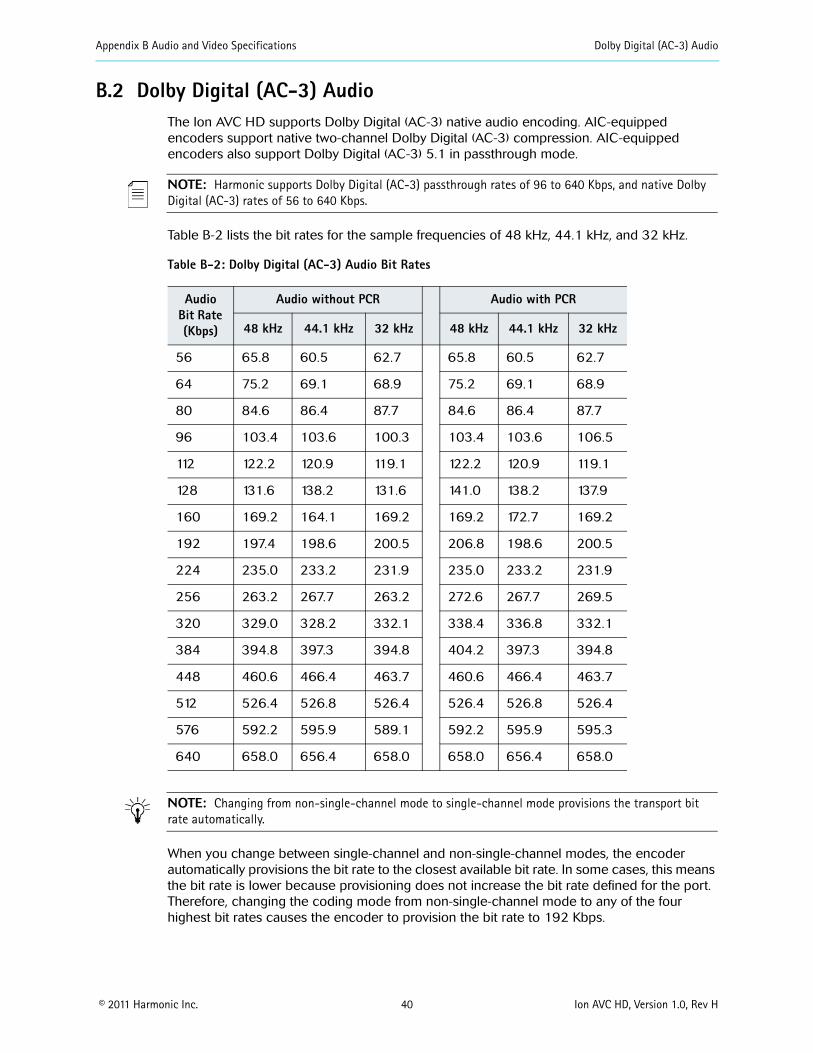
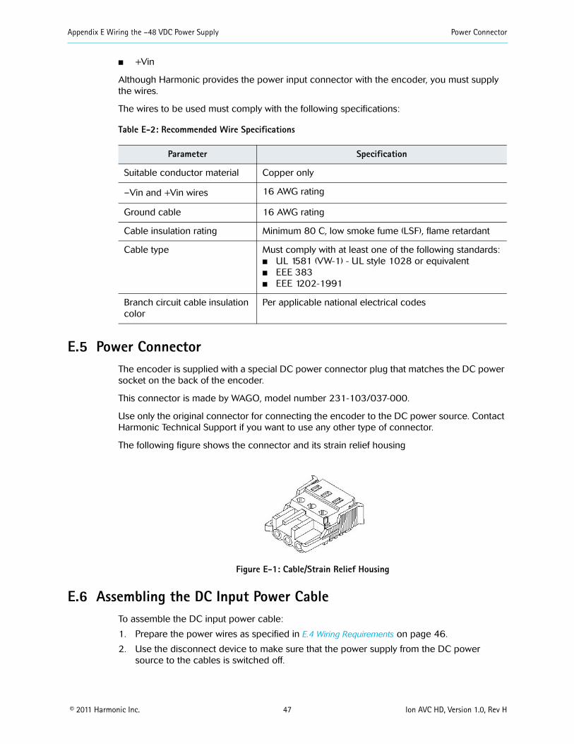

Appendix F DiviComtrade FLEX Decoding Module Audio Decode Specifications
copy 2011 Harmonic Inc 51 Ion AVC HD Version 10 Rev H
F4 Audio Decode SpecificationsTable F-3 describes the audio decode specifications supported by the FLEX module
Table F-3 FLEX Audio Decode Specifications
Feature Support
Audio Decoding
Decoding Mode
Audio Formats (MPEG-1 Layer II AC-3)
Compression Mode
Additional Support
NOTE Audio leveling is also supported by the FLEX decoding module This feature defines a constant gain adjustment for incoming audio signal
F41 Decoding Resource ConsiderationsA multichannel decode stream counts as 3 stereo decode streams If no downmixing and no dynamic level adjustment is enabled on any stream the absolute maximum number of audio decode streams is 8 allowed in one of these (and only these) combinations
Up to 4 monostereo decode streams per FLEX decoding port
Up to one multichannel audio decode and one stereo decode stream per FLEX decoding port
Up to 2 multichannel audio decode and 2 stereo audio decode streams on the first FLEX decoding port
Up to 8 monostereo decode streams on the first FLEX decoding port (with no audio on second port)
See Table F-4 on page 52 for information on AC-3 resource considerations
Static Level Adjustment Dynamic Level Adjustment
Dolby AC-3 with multichannel decoding and downmixing
Dolby AC-3 Mono and Stereo decoding
Mono and stereo (20)
(AC-3) Line mode and RF line mode
Support for multiple deocde of the same PID (audio decode)
Table F-4 AC-3 Resource Considerations
Input Format Audio Input (into card) Decoding Mode
Multichannel DownMix checkbox
Result
Resource Usage
Equivalent
AC-3
Mono
Mono Available Audio on the left channel Silence on the right channel
Stereoa
Stereo Audio on both channels
3 x Stereo
Multichannel No Audio on the Center channel Silence on all others
3 x Stereo
Stereo
Mon Available (irrelevant for this decoding mode)
Audio on the left channel Silence on the right channel
Stereoa
Stereo Audio on both channels
Multichannel No Audio on both left and right channels Silence on all others
3 x Stereo
AC-3 (continued)
Multichannel
Mono Available (must be enabled for this decoding mode or an alarm is raised and decoding stops)
Multichannel downmix to Mono on the left channel
Stereoa
Stereo Audio on both channels
Multichannel No Audio on both left and right channels Silence on all others
3 x Stereo
Appendix F DiviComtrade FLEX Decoding Module Audio Decode Specifications
copy 2011 Harmonic Inc 52 Ion AVC HD Version 10 Rev H
Appendix F DiviComtrade FLEX Decoding Module Ancillary Data Specifications
copy 2011 Harmonic Inc 53 Ion AVC HD Version 10 Rev H
See Table F-5 on page 53 for information on MPEG-L2 resource considerations
Table F-5 MPEG-L2 Resource Considerations
Input Format Audio Input (into card)
Decoding Mode Result Resource Usage
Equivalent
MPEG-L2
Mono Mono Audio on left channel Silence on right channel StereoStereo
Stereo Mono Audio on both channels
Stereo
F5 Ancillary Data SpecificationsA multichannel encoder equipped with FLEX is essentially receiving and outputting compressed streams Therefore the terminology used regarding ancillary data can be incorrect or misleading VBI data is not applicable to fully digital signals but is used by user habit The FLEX module does not re-create any of the ancillary data it simply passes it intact as packets of bits to the associate encoderrsquos TS output
Table F-6 describes the ancillary data specifications supported by the FLEX module
Table F-6 Ancillary Data Specifications
Feature Support
Vertical Interval Data Services (Pass through only)
WST (Teletext) Inverted WST WSS VPS AFD and bar data VITC Closed Captioning per CEA-608 and 708 AMOL and TV Guide data
Number of channels 4 PIDS
F6 Input SpecificationsTable F-7 describes the input specifications supported by the FLEX module
a Enabling Multichannel downmixing allocates resources for downmixing resulting in resource usage equivalent to 3 x Stereo
Table F-7 Input Specifications
Feature Support
Transport stream Inputs MPEG-2 TS
ASI interface (optional module)
Connector 4x BNC 75 Ω
MPEG format 188 Bytes per TS packet
Appendix F DiviComtrade FLEX Decoding Module Output Specifications
copy 2011 Harmonic Inc 54 Ion AVC HD Version 10 Rev H
F7 Output SpecificationsTable F-8 describes the output specifications supported by the FLEX module
Table F-8 Outputs Specifications
Feature Support
Video Outputs
Connector Type
Embedded Data along the Video
F8 Environmental and Physical Compliant with ROHS Directive 200295EC Refer to the encoder environmental specifications for additional information
Processing 1 MPTSSPTS per port Up to 150 Mbps per port
ASI Ports 4
IP interface (optional module)
Type Gigabit Ethernet
IP ports 2 Independent ports
Connector 2 x copper SFPs
Speed 1 x 1000 Mbps per port
IP encapsulation MPEG-2 TS over UDPIP 1 to 7 TS IP
MPEG format 188 Bytes per TS packet
MPEG-2 TS MPTS and SPTS
Maximum Bit-Rate per Socket
80 Mbps
Addressing Unicast and multicast
Management IGMP ARP and ICMP
Forward Error Correction (FEC)
The FLEX module supports SMTE 2022 Annex C forward error correction (FEC) FEC provides lost packet recovery at the receiving devices
RF Input Card
For specifics see Appendix G on page 74
One (1) per decoded channel with video only SDI or HD-SDI One (1) additional per channel for confidence monitoring only
DIN 1023 (DIN 1023 to BNC adapters available)
No Audio VBI VANC or HANC data embedded The data are embedded into the SDIHD-SDI output
Table F-7 Input Specifications
Feature Support
Appendix F DiviComtrade FLEX Decoding Module Module Slots
copy 2011 Harmonic Inc 55 Ion AVC HD Version 10 Rev H
F9 Module SlotsThe diagram below represents the back panel of typical encoder The diagram shows the slot number and the modules that can be installed in that slot NMX or Configuration Manager uses the slot number to differentiate between cards of the same type within the encoder
Slot 2
Slot 1 Slot 3
Slot 4 FLEX
Main Board
Slot 5 FLEX
F10 Installing the FLEX Decoding ModuleThis section describes how to install the FLEX Decoding Module The modulersquos ports are shown in Figure F-1 on page 49
Host encoders encoders are typically ordered from the factory with the FLEX module already installed However if additional FLEX modules are installed installation of the FLEX module in the field would be required
F1001 ESD Safety Precautions
To protect modules from electrostatic discharge (ESD) follow these safety precautions
Always wear a properly grounded antistatic wrist strap whenever handling the modules
Keep the module inside the antistatic bag until you are ready to install the module in a chassis
F101 Installing a ModuleBefore installing the FLEX module you may need to upgrade the software version on the encoder Contact Harmonic Customer Support to find out which software version you need to install the additional module
There is also a CPC limitation that requires version 105
NOTE Before making changes to the FLEX module make sure the service configuration is cleared before powering down the system Also before installing the FLEX module make sure that the encoder has the appropriate software version installed before installing the module using either NMX or the Configuration Manager
NOTE The FLEX module must be installed in slot 4 (and an optional second module in slot 5) of the encoder
You need a Phillipstrade screwdriver to install the FLEX module
To install the FLEX module
1 Turn off the encoder in which you are installing the module
2 Remove the protective covers from slots 1 through 5 where you are going to install the module (by loosening the two screws with the Phillips screwdriver)
Save the cover for future use
3 While wearing an ESD wrist strap unpack the module from its antistatic protective packing material
Appendix F DiviComtrade FLEX Decoding Module Cabling the FLEX Module
copy 2011 Harmonic Inc 56 Ion AVC HD Version 10 Rev H
CAUTION Unpack and handle the module away from electric motors transformers and other similar machinery
4 Slide the module onto the encoder by lining up the edges of the module with the slots in the chassis
Make sure that the FLEX module goes into the encoder smoothly without binding or scraping other modules The modules should slide easily until you feel the module engage the internal connector and the module is flush with the back of the encoder Do not force the module
5 Tighten the two screws with the screwdriver
NOTE Refer to the encoder guide or online help for information about accommodating the new FLEX module in the encoderrsquos configuration
F11 Cabling the FLEX ModuleThis section describes how to cable the FLEX module Cabling the FLEX module is very straight forward All video and monitor ports are clearly marked The following table lists the ports and required connectors
NOTE Video ports can either be used for loopback or confidence monitoring
Each firmware license ships with two video loopback cables An optional adapter cable can be purchased for use with the monitoring ports You must also have an IP input module installed Figure F-3 on page 57 provides additional information on understanding the encoderrsquos LED color values
F12 Re-Encode Chassis Scenarios This section describes two recommended re-encode chassis scenarios 2- Channel and 4-Channel scenarios
F121 2 - ChannelFigure F-1 on page 49 illustrates a typical 2-channel re-encode chassis cabling assignment This scenario makes use of a base 2-channel encoder chassis Table F-9 describes the port and cable associations
NOTE For the monitor ports there is a DIN to BNC pigtail connector that can be ordered Harmonic Part number FLEX-MON 229-0054067
Table F-9 Port and Cable Assignments (2-channel)
Port Description Connector
Video 1 75 Ω cable DIN 1023
Appendix F DiviComtrade FLEX Decoding Module Re-Encode Chassis Scenarios
copy 2011 Harmonic Inc 57 Ion AVC HD Version 10 Rev H
NOTE The FLEX module must use slot 4
Figure F-2 2 - Channel Re-Encode Chassis (Cable) Scenario
Figure F-3 describes the LED colors and what they represent
720p
Figure F-3 LED Color Chart
Monitor 1 75 Ω cable This output port is used for the loopback cable that feeds an encoder
DIN 1023
Video 2 75Ω cable DIN 1023
Monitor 2 75 Ω cable The second output port can be used as a monitoring and troubleshooting purposes
DIN 1023
IP Module
Audio Module
Audio Module
FLEX Module
Attaches to optional SDI monitor (video only)
Table F-9 Port and Cable Assignments (2-channel)
Appendix F DiviComtrade FLEX Decoding Module Configuring the FLEX Module in NMX
copy 2011 Harmonic Inc 58 Ion AVC HD Version 10 Rev H
F122 4 - ChannelFigure F-4 illustrates a typical 4-channel re-encode chassis cabling assignment This scenario makes use of a base 4-channel encoder chassis
Table F-10 Port and Cable Assignments
Port Description Connector
Video 1 75 Ω cable DIN 1023
Monitor 1 75 Ω cable This output port is used for the loopback cable that feeds an encoder
DIN 1023
Video 2 75Ω cable DIN 1023
Monitor 2 75 Ω cable The second output port can be used as a monitoring and troubleshooting purposes
DIN 1023
Video 3 75Ω cable DIN 1023
Video 4 75Ω cable DIN 1023
IP Module Audio Module
Attaches to optional SDI monitor
FLEX Module
Figure F-4 4 - Channel Re-Encode Chassis (Cable) Scenario
F13 Configuring the FLEX Module in NMXRefer to the NMX online help system for configuring a FLEX module for use in your NMX Digital Service Manager application
copy 2011 Harmonic Inc 59 Ion AVC HD Version 10 Rev H
Appendix GDivicomtrade RF Input Card
This Appendix contains specifications for the DiviCom RF Input card
The RF Input card is a four channel ATSC 8VSB receiver It receives four independent ATSC 8VSB signals on its inputs and outputs four MPEG-2 Transport Streams over the chassis internal bus to one or more FLEX decoding modules The RF Input card does not support analog demodulation
The RF Input card can be managed by either NMX or SAG Figure G-1 on page 59 shows a diagram of the rear panel
Figure G-1 RF Input card
The LED lights show status as shown in Table G-1 on page 59
Table G-1 LED status lights
Display Status
Off Port disabled
Blinking Yellow Loss of synch
Red Packet error rate (PER) threshold exceeded
Steady yellow SNR below threshold
Green Port Enabled no alarms
G1 RF SpecificationsThe RF specifications for the card are listed below
VSB Input 4 Type lsquoFrsquo connectors per IEC 60169-24
Tuning Range VHFUHF (Channels 2-59)
NOTE Tuning range is limited to Channels 2 to 59 by software per the FCCIndustry Canada decisions to release channels 60 to 69 for public safety use
Sensitivity --83 dBm6 MHz
Dynamic Range gt 80dB
Appendix G Divicomtrade RF Input Card Output Specifications
copy 2011 Harmonic Inc 60 Ion AVC HD Version 10 Rev H
G2 Output SpecificationsThe output specification for the card is
Four MPEG-2 Transport Streams per ATSC A53 Part 3 and ISOIEC 13818-1
G3 Environmental and Physical Compliant with ROHS Directive 200295EC Refer to the encoder environmental specifications for additional information
copy 2011 Harmonic Inc 61 Ion AVC HD Version 10 Rev H
Appendix HAB Power Switch
H1 IntroductionThis appendix contains specifications for the AB Power switch
The AB Power switch receives two separate AC main input sources (to support redundancy) monitors the voltage and selects the good voltage to provide one AC output for input into either the AC or DC power supply The AB Power switch automatically changes from the line A input to the Line B input (or the reverse) upon loss of power on the active line The AB Power switch uses and monitors the active line continuously and switches to the backup port only when the active line has a fault The card switches back automatically when the active port is detected as normal and stable (with an appropriate delay)
NOTE The AB Power switch is a dual-height card and can only be installed in slots 1 and 3
The AB Power switch can be managed by SAG Figure H-1 shows a illustration of the AB Power switch
Pigtail power output cable(plugs into encoder)
Figure H-1 AB Power switch
Appendix H AB Power Switch Card Status
copy 2011 Harmonic Inc 62 Ion AVC HD Version 10 Rev H
H2 Card StatusThis section describes how to recognize the current status of the AB Power switch through its LEDs
NOTE It is recommended that you use A for primary equipment and B for backup equipment
The LED lights show card status as shown in Table H-1 on page 62
Table H-1 LED status lights
Display Status
Red Input power (for that port) is not within the acceptable voltage range
Green Steady input power for that port is within acceptable voltage rangeFlashing port is being utilized for input power
Orange Port failure (canrsquot be used)
Off No power or broken LED
copy 2011 Harmonic Inc 63 Ion AVC HD Version 10 Rev H
AAC power supply
connecting 25overview 17
agency approvals 4air filters 31 to 32airflow 21alphanumeric keys 27audio cables connecting 24audio compression rates described 40audio encoding features 13
Bback panel
described 16Ethernet management port 18 35fault relay port 18fuse 17IP output port 18LEDs 18port specifications 35serial data port 18video input ports 17
boot sequence 44
Ccabling the encoder 24compliance and approval 2connecting
audio input cables 24DC power supply 46Ethernet management cable 25IP output cables 25video input cables 25
connections FCC compliance 2connectors
AC power 17Ethernet 18 35fault relay 36IP output 18RJ-45 18 35video 35
cTUVus North American safety approval 4
DDC power supply 46digital program insertion 14display front panel 28Dolby Digital AC-3 bit rates 40DPI 14
Eenvironmental specifications 34Ethernet management port
connecting cable 25described 18specifications 35
European EMIEMC approvals 4
Ffault relay port 18 36FCC compliance 2features
audio encoding 13general 10video encoding 12
filters See air filters 31front bezel 15
removing 23front panel 15 27front panel display 28function keys 27fuse 32
Hhardware specifications 34Harmonic equipment modifying 2Harmonic Heartbeat Protocol 14help displaying on VFD 28HHP 14hot keys 27
Iinstalling the encoder 20IP output port
connecting cables 25described 18
Kkeypad 27
LLEDs
audio port 19back panel 18front panel 15video port 19
loading new software 45local control panel
described 15display 28
MMAC address viewing 29maintaining air filters 31maintaining fuse 32
Nnavigation keys 27North American EMI approvals 4North American Safety approvals 4
Ooutput port IP 18 25
Ppinouts port 35port specifications 35ports
Ethernet management 18
Index
Index
copy 2011 Harmonic Inc 64 Ion AVC HD Version 10 Rev H
fault relay 18IP output 18serial data 18video input 17
power supplyAC 25DC 46specifications 34
Rrack mounting 20rack rails attaching 22rack-mount kit 20replacing air filters 32resetting the encoder 44RJ-45 connectors 18 35
Sserial data port 18specifications
environment 34fuse 34hardware 34input and output 35port 35power supply 34video 41
standards and approvals 4
TTUV European safety approval 4
Uunpacking the encoder 20
VVFD
display during boot 44paths represented 28
video encoding features 12video input ports
connecting cables 25description 17LEDs 19
video specifications 41
WWEEE compliance 2
Harmonic Inc4300 North First StreetSan Jose CA 95134 USAT +1 408 542 2500 F +1 408 490 6708
wwwharmonicinccom
copy Copyright 2011 Manual Part No MAN-AVC-HD-INST-01
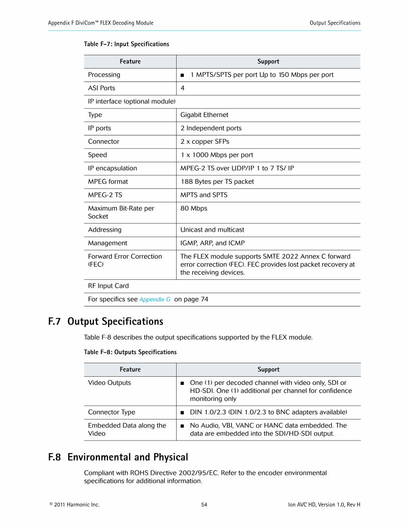
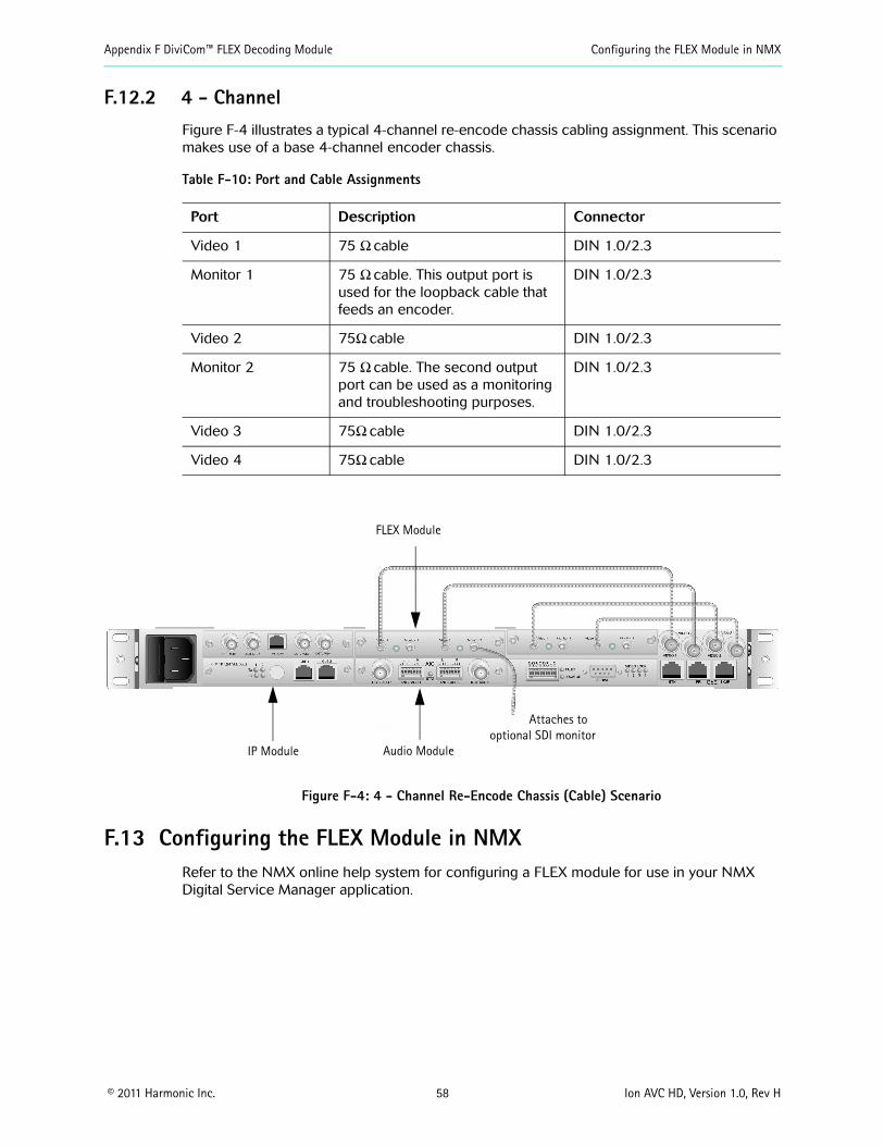
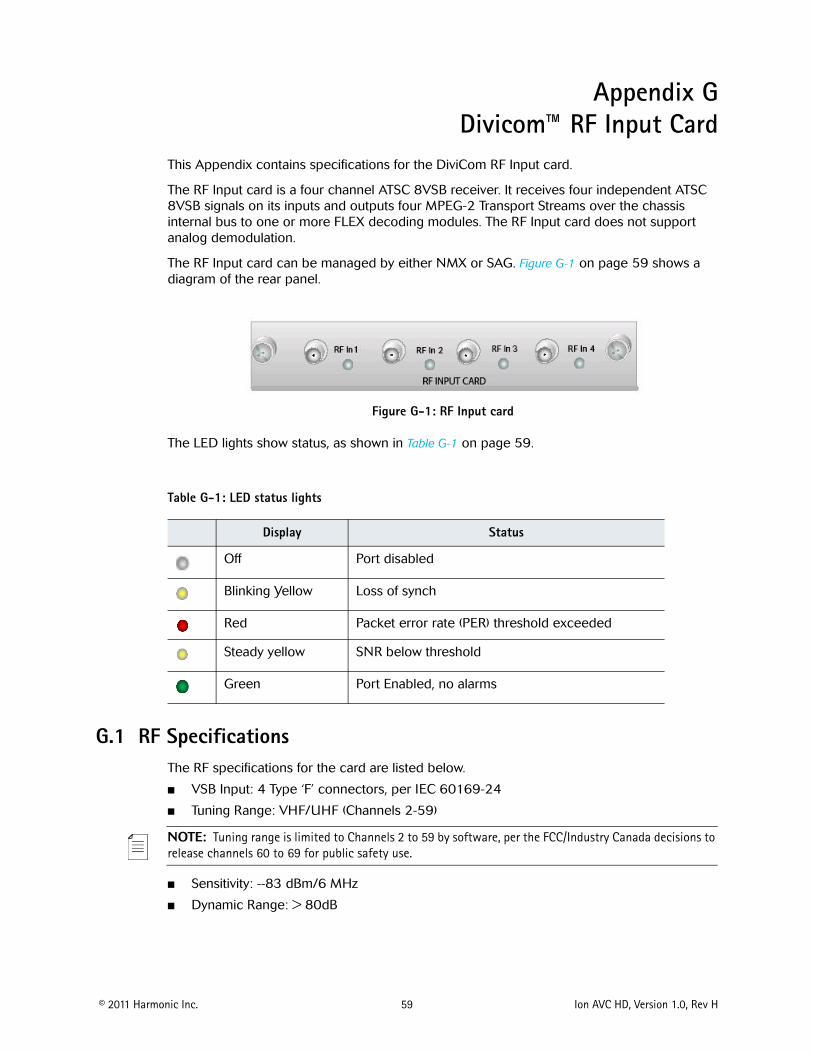
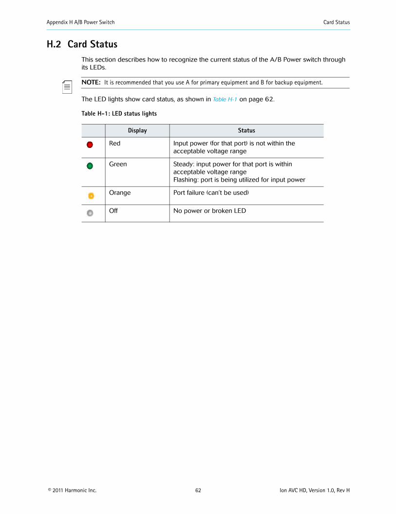
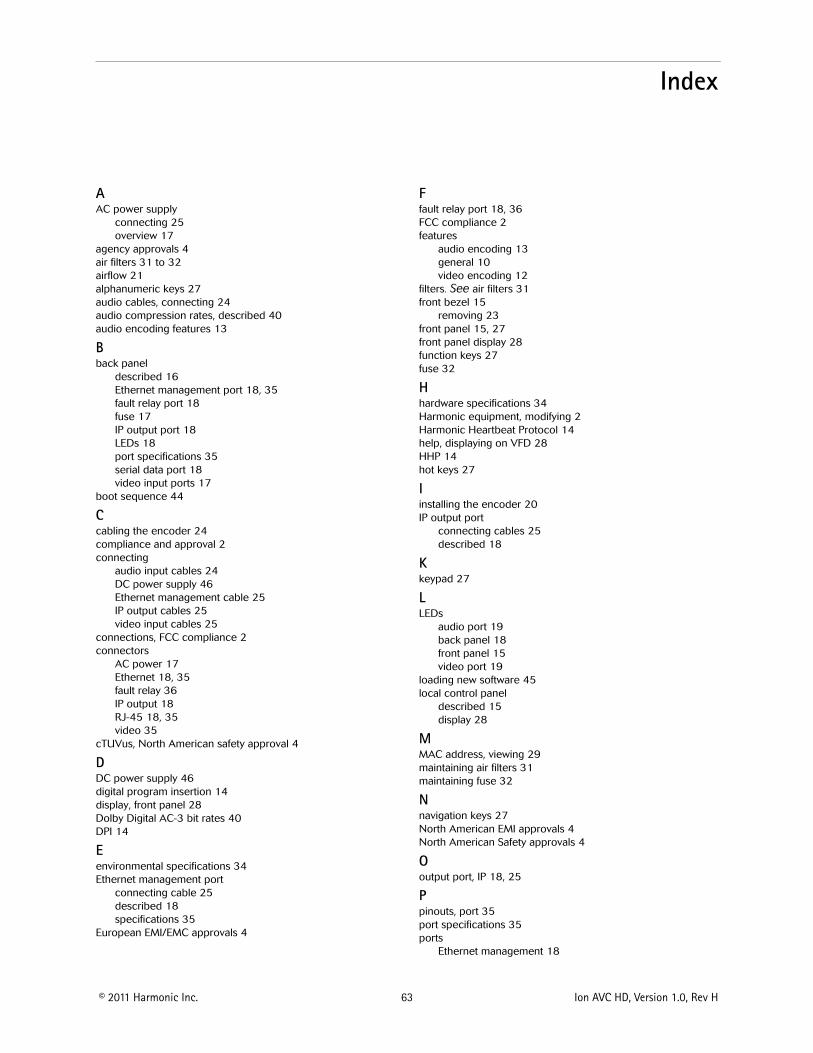

Harmonic Inc4300 North First StreetSan Jose CA 95134 USAT +1 408 542 2500 F +1 408 490 6708
wwwharmonicinccom
copy Copyright 2011 Manual Part No MAN-AVC-HD-INST-01


![The Food Standards Agency · £10.50 [sterling] The Food Standards Agency Contents Contents ... Donald Dewar Ron Davies Mo Mowlam. The Food Standards Agency Chapter 1 Introduction](https://img.pdfslide.us/doc/110x75/5fcb09dff31abb7c4014ce8b/the-food-standards-agency-1050-sterling-the-food-standards-agency-contents.jpg)