Embed Size (px)
Citation preview
Computers & Graphics 25 (2001) 295}308
Technical Section
Di!usion rendering of black ink paintings using new paperand ink models
Jintae Lee*
Department of Computer Software, University of Aizu, Aizu-Wakamatsu City, Fukushima 965-8580, Japan
Abstract
A practical technique is presented for e$ciently rendering oriental black ink paintings with realistic di!usion e!ects,being based on models which simulate a variety of paper types and black ink properties. Strokes can be generated bybristles or elastic brush models simulating those actually used in oriental black ink painting. Incorporation of papermodeling allows users to draw on a wide variety of papers having either randomly generated "ber meshes or uniformmeshes commonly found in fabrics which are also frequently used. This accordingly provides a unique platform forreal-time dynamic simulation of realistic ink di!usion in that the resultant di!usion images re#ect the texture and theglobal change of gray tones as well as local temporal variations speci"c to a particular paper. Examples are presenteddemonstrating the capability of the proposed technique for handling di!erent ink and paper properties. � 2001 ElsevierScience Ltd. All rights reserved.
Keywords: Di!usion rendering; Soft brush; Paper modeling; Fiber mesh; Oriental black ink painting
1. Introduction
The traditional Asian art form of black ink paintingtook root more than 3000 years ago [1,2]. Displayingdynamic formations, delicate gray shading tones, andimpressive textures with only a few strokes have attractednumerous researchers in computer-simulation attempts.While the technique may initially appear to be simple, theabundant number of expressive rendering e!ects, andtheir subsequent simulation, serve to arouse increasingresearch interest among computer scientists.
Black ink rendering is non-photo realistic rendering[3}7] which stands in contrast to conventional computergraphics rendering methods that strive for photo realism,e.g., ray tracing and radiosity. In fact, it is even distinctcompared to general non-photo realistic rendering suchas digital painting, picture retouching, or illustrationgeneration; methods which involve a wide range ofcolors, rich editing functions, and various brush patterns,
*Tel.: #81-242-37-2567; fax: #81-242-37-2743.E-mail address: [email protected] (J. Lee).
but which do not involve the brush models, special paper,or ink used in black ink painting.
The brush used in black ink painting has long, star-ched natural bristles which narrow to a pointed tip. Thebristles, typically made from the hair of rabbits, martins,badgers, horses, or deer, move with elastic deformationon the paper such that 3D visual information is providedto the artist; a crucial feature to timely guide the brushdirection. The paper used in black ink painting di!ersfrom that typically used in watercolor painting, beingmuch thinner and more textured. Moreover, it has littlesheen and is quite absorbent; a feature which allows thepainted #uid to more easily #ow along its "bers. Theemployed black ink is a dilute mixture of water andcolloidal black carbon particles in which the carbonparticles are much smaller than those of watercolorpaints such that they can di!use into paper along withthe absorbed water. One early attempt to simulate blackink painting applied conventional 2D rendering tech-niques, i.e., in order to synthesize the stroke producedusing hair bristle brushes, the outline of brush strokeswas described as a sequence of connected BeH zier orB-spline curves [8,9]. The curves are developed using 2Ddrafting software in conjunction with mouse or pen input
0097-8493/01/$ - see front matter � 2001 Elsevier Science Ltd. All rights reserved.PII: S 0 0 9 7 - 8 4 9 3 ( 0 0 ) 0 0 1 3 2 - 1
and scaling/editing control points. Produced strokes are"lled with image patterns incorporating a set of shadevariation e!ects, after which they can be modi"ed byreapplying the same 2D drafting and "lling functions.While this approach gives precise, smooth outlines withvariations in shading, the mode of access is limited by theemployed drawing process due to the fact that strokeediting is restricted to altering control points thatdetermine stroke boundaries.
Other attempts were also made to apply photoretouching techniques or paint tools developed for water-color painting to black ink painting. Haeberlis usedsimple primitives such as points, lines, triangles, and 2Dpatterns on a photo retouching system to generate ortransform strokes [10], while Curtis introduced a modelwhich simulated watercolor painting and black ink ren-dering e!ects [11].
Many commercial photo retouching softwares anddigital paint tools are currently available. Adobe Photo-shop, a well-known commercial product, incorporatesa Gaussian blurring "lter that allows users to paintsoft-edged strokes or blur a stroke. Fractal DesignPainter is another popular commercial system that hasmany e!ective paint tools for simulating various paintingmaterials and touch e!ects [12]. Its brush pallet hasseveral types of pixel brushes that simulate the art e!ectsproduced by crayons, chalk, an airbrush, watercolors,and oil paints; while its art material pallet provides manytypes of paper texture patterns for representing theroughness of a paper's surface. The software, however, islimited in its ability to obtain realistic black ink paintinge!ects in that the resulting strokes are blurred globallyand the color around the edges of the strokes is lighterthan the inside part, simulating feathering e!ects ofwatercolor rather than of black ink. In black ink render-ing, the rendering of individual strokes changes delicatelyaccording to the ink status, speed, and movement of thebrush.
Taken together, it becomes clear that the inherentrestrictions in commercial software for generating blackink painting are mainly due to the special characteristicsof the particular materials used. Researchers attemptingto simulate oriental black ink painting have realized suchrequirements and accordingly considered the possibilityof modeling brushes and papers [13,14] or to instead usereal tools [15,16]. Strassman proposed a physical modelfor representing brush strokes and rendering, i.e., thebrush is considered as a 1D array of bristles and movedsuch that it is always perpendicular to the path of thestroke de"ned by a set of position and pressure para-meters in which pressure determines stroke width [13].While this approach does indeed enable users to producebrush strokes by moving a brush model, the brush modelitself could still be improved, especially with regard toblack ink painting. That is, as the brushes are simply 2Dpatterns like rubber stamps, users cannot see how the
shape of the bristles is transformed as bristles are pulled,turned, pressed down, or lifted up; visual informationwhich is essential for users to have so as to better controlbrush movement. Moreover, because such imaginarybristles do not bend, the timing in which pressure isexerted on the brush is quite di!erent compared to thatof a real brush; hence users cannot utilize acquired paint-ing skills developed over a lifetime. Most recently, weproposed a new brush model that overcomes the inherentdrawbacks of Strassman's brush model, i.e., we developed3D `softa brushes in which the shape of the bristles variesdynamically in response to the forces imposed on it bythe paper [17].
Although orientation and density of "bers, as well asbrush shape, are required to perform black ink rendering,only the local ground roughness of the paper is requiredfor modeling the spreading of watercolor. In 1991, Guoand Kunii proposed a basic "ber mesh paper model forsynthesizing black ink di!usion [18]. This approach pro-duced di!usion images based on a paper model, yetproblems arise in that their model considered randomlydistributed "bers, but did not take into account thematerial and texture of the paper, nor was the dynamicprocess of ink and image density variation included.
Here, we present a complete black ink di!usion ren-dering method which considers the characteristics ofblack ink and also incorporates a random or regular "bermesh structured paper model. Using this new method inconjunction with our previously proposed brush model[17] improves black ink di!usion rendering approachesin several aspects: (1) the user can select a wide variety ofpaper textures, (2) realistic di!usion images can be drawnre#ecting the paper material and ink characteristics,(3) the e$cient and novel rendering algorithm is applic-able to synthesize di!usion e!ects for other art styles aswell.
Section 2 provides a brief explanation of ink di!usionphenomena, while Section 3 gives an overview of the softbrush used for creating brush strokes. Section 4 thendiscusses the modeling of paper and parameters thatde"ne the geometry of the "ber mesh, after which Sec-tion 5 describes the di!usion rendering algorithm basedon the paper model. Typical di!usion images createdwith these techniques are presented in Section 6, beingfollowed by Section 7 in which di!usion rendering isapplied to a variety of paper types.
2. Ink di4usion phenomena
Di!usion of the painted #uid is perhaps the mostadmired feature of this unique art form. A type of haloappearing around the original stroke adds a mysterioustouch, being caused by letting ink spread beyond thestroke's original border, while ink seeping into specialpaper with high absorbency creates a feathery, blurred
296 J. Lee / Computers & Graphics 25 (2001) 295}308
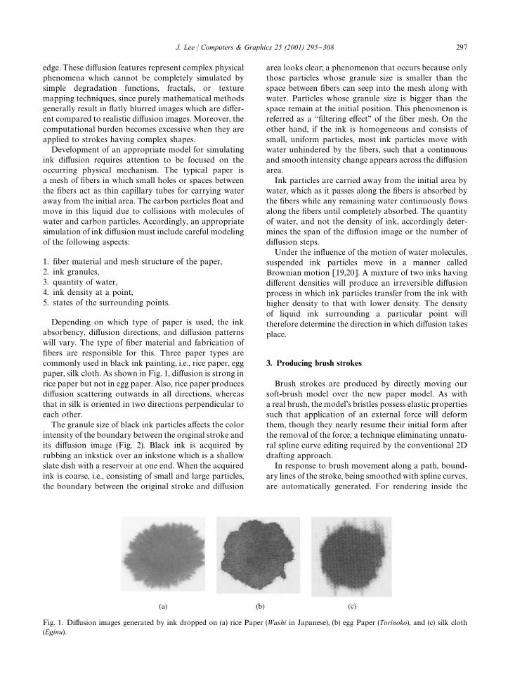
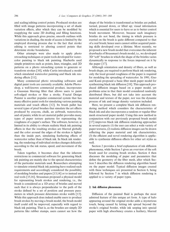
Fig. 1. Di!usion images generated by ink dropped on (a) rice Paper (Washi in Japanese), (b) egg Paper (Torinoko), and (c) silk cloth(Eginu).
edge. These di!usion features represent complex physicalphenomena which cannot be completely simulated bysimple degradation functions, fractals, or texturemapping techniques, since purely mathematical methodsgenerally result in #atly blurred images which are di!er-ent compared to realistic di!usion images. Moreover, thecomputational burden becomes excessive when they areapplied to strokes having complex shapes.
Development of an appropriate model for simulatingink di!usion requires attention to be focused on theoccurring physical mechanism. The typical paper isa mesh of "bers in which small holes or spaces betweenthe "bers act as thin capillary tubes for carrying wateraway from the initial area. The carbon particles #oat andmove in this liquid due to collisions with molecules ofwater and carbon particles. Accordingly, an appropriatesimulation of ink di!usion must include careful modelingof the following aspects:
1. "ber material and mesh structure of the paper,2. ink granules,3. quantity of water,4. ink density at a point,5. states of the surrounding points.
Depending on which type of paper is used, the inkabsorbency, di!usion directions, and di!usion patternswill vary. The type of "ber material and fabrication of"bers are responsible for this. Three paper types arecommonly used in black ink painting, i.e., rice paper, eggpaper, silk cloth. As shown in Fig. 1, di!usion is strong inrice paper but not in egg paper. Also, rice paper producesdi!usion scattering outwards in all directions, whereasthat in silk is oriented in two directions perpendicular toeach other.
The granule size of black ink particles a!ects the colorintensity of the boundary between the original stroke andits di!usion image (Fig. 2). Black ink is acquired byrubbing an inkstick over an inkstone which is a shallowslate dish with a reservoir at one end. When the acquiredink is coarse, i.e., consisting of small and large particles,the boundary between the original stroke and di!usion
area looks clear; a phenomenon that occurs because onlythose particles whose granule size is smaller than thespace between "bers can seep into the mesh along withwater. Particles whose granule size is bigger than thespace remain at the initial position. This phenomenon isreferred as a `"ltering e!ecta of the "ber mesh. On theother hand, if the ink is homogeneous and consists ofsmall, uniform particles, most ink particles move withwater unhindered by the "bers, such that a continuousand smooth intensity change appears across the di!usionarea.
Ink particles are carried away from the initial area bywater, which as it passes along the "bers is absorbed bythe "bers while any remaining water continuously #owsalong the "bers until completely absorbed. The quantityof water, and not the density of ink, accordingly deter-mines the span of the di!usion image or the number ofdi!usion steps.
Under the in#uence of the motion of water molecules,suspended ink particles move in a manner calledBrownian motion [19,20]. A mixture of two inks havingdi!erent densities will produce an irreversible di!usionprocess in which ink particles transfer from the ink withhigher density to that with lower density. The densityof liquid ink surrounding a particular point willtherefore determine the direction in which di!usion takesplace.
3. Producing brush strokes
Brush strokes are produced by directly moving oursoft-brush model over the new paper model. As witha real brush, the model's bristles possess elastic propertiessuch that application of an external force will deformthem, though they nearly resume their initial form afterthe removal of the force; a technique eliminating unnatu-ral spline curve editing required by the conventional 2Ddrafting approach.
In response to brush movement along a path, bound-ary lines of the stroke, being smoothed with spline curves,are automatically generated. For rendering inside the
J. Lee / Computers & Graphics 25 (2001) 295}308 297
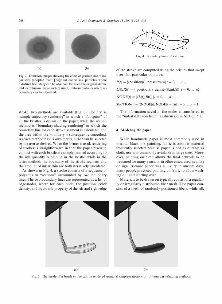
Fig. 2. Di!usion images showing the e!ect of granule size of inkparticles (adopted from [24]): (a) coarse ink particles wherea distinct boundary can be observed between the original strokeand its di!usion image and (b) small, uniform particles where noboundary can be observed.
Fig. 3. The inside of a brush stroke can be rendered using (a) simple-trajectory or (b) boundary-shading methods.
Fig. 4. Boundary lines of a stroke.
stroke, two methods are available (Fig. 3). The "rst is`simple-trajectory renderinga in which a `footprinta ofall the bristles is drawn on the paper, while the secondmethod is `boundary-shading renderinga in which theboundary line for each stroke segment is calculated andthe area within the boundary is subsequently smoothed.As each method has its own merits, either can be selectedby the user as desired. When the former is used, renderingof strokes is straightforward in that the paper pixels incontact with each bristle are simply painted according tothe ink quantity remaining in the bristle; while in thelatter method, the boundary of the stroke segment andthe amount of ink within are both iteratively calculated.
As shown in Fig. 4, a stroke consists of a sequence ofpolygons or `sectionsa surrounded by two boundarylines. The two boundary lines are represented as a list ofedge-nodes, where for each node, the position, colordensity, and liquid ink property of the left and right edge
of the stroke are computed using the bristles that sweptover that particular point, i.e.
P(t)"�(position(t), pressure(t)) � t"0,2, n�,
¸(t),R(t)"�(position(t), density(t),ink(t)) � t"0,2, n�,
NODE(t)"�(¸(t),R(t)) � t"0,2, n�,
SECTION(t)"�(NODE(t), NODE(t#1)) � t"0,2, n!1�.
The information saved in the nodes is transferred tothe `initial di!usion fronta as discussed in Section 5.1.
4. Modeling the paper
While handmade paper is most commonly used inoriental black ink painting, fabric is another materialfrequently selected because paper is not as durable ascloth, nor is it commonly available in large sizes. More-over, painting on cloth allows the "nal artwork to betreasured for many years, or in other cases, used as a #agor sign. Because paper was a luxury in ancient days,many people practiced painting on fabric to allow wash-ing out and starting over.
Materials to be drawn on typically consist of a regular-ly or irregularly distributed "ber mesh. Rice paper con-sists of a mesh of randomly positioned "bers, while silk
298 J. Lee / Computers & Graphics 25 (2001) 295}308
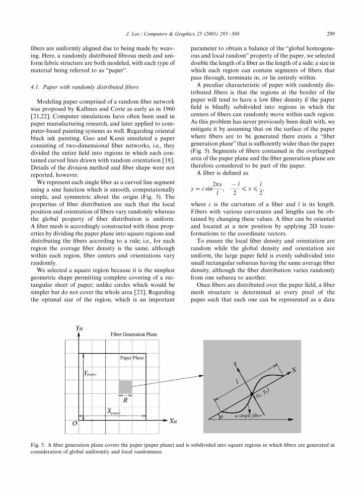
Fig. 5. A "ber generation plane covers the paper (paper plane) and is subdivided into square regions in which "bers are generated inconsideration of global uniformity and local randomness.
"bers are uniformly aligned due to being made by weav-ing. Here, a randomly distributed "brous mesh and uni-form fabric structure are both modeled, with each type ofmaterial being referred to as `papera.
4.1. Paper with randomly distributed xbers
Modeling paper comprised of a random "ber networkwas proposed by Kallmes and Corte as early as in 1960[21,22]. Computer simulations have often been used inpaper manufacturing research, and later applied to com-puter-based painting systems as well. Regarding orientalblack ink painting, Guo and Kunii simulated a paperconsisting of two-dimensional "ber networks, i.e., theydivided the entire "eld into regions in which each con-tained curved lines drawn with random orientation [18].Details of the division method and "ber shape were notreported, however.
We represent each single "ber as a curved line segmentusing a sine function which is smooth, computationallysimple, and symmetric about the origin (Fig. 5). Theproperties of "ber distribution are such that the localposition and orientation of "bers vary randomly whereasthe global property of "ber distribution is uniform.A "ber mesh is accordingly constructed with these prop-erties by dividing the paper plane into square regions anddistributing the "bers according to a rule; i.e., for eachregion the average "ber density is the same, althoughwithin each region, "ber centers and orientations varyrandomly.
We selected a square region because it is the simplestgeometric shape permitting complete covering of a rec-tangular sheet of paper; unlike circles which would besimpler but do not cover the whole area [23]. Regardingthe optimal size of the region, which is an important
parameter to obtain a balance of the `global homogene-ous and local randoma property of the paper, we selecteddouble the length of a "ber as the length of a side; a size inwhich each region can contain segments of "bers thatpass through, terminate in, or lie entirely within.
A peculiar characteristic of paper with randomly dis-tributed "bers is that the regions at the border of thepaper will tend to have a low "ber density if the paper"eld is blindly subdivided into regions in which thecenters of "bers can randomly move within each region.As this problem has never previously been dealt with, wemitigate it by assuming that on the surface of the paperwhere "bers are to be generated there exists a `"bergeneration planea that is su$ciently wider than the paper(Fig. 5). Segments of "bers contained in the overlappedarea of the paper plane and the "ber generation plane aretherefore considered to be part of the paper.
A "ber is de"ned as
y"c sin2�x
l,
!l
2)x)
l
2,
where c is the curvature of a "ber and l is its length.Fibers with various curvatures and lengths can be ob-tained by changing these values. A "ber can be orientedand located at a new position by applying 2D trans-formations to the coordinate vectors.
To ensure the local "ber density and orientation arerandom while the global density and orientation areuniform, the large paper "eld is evenly subdivided intosmall rectangular subareas having the same average "berdensity, although the "ber distribution varies randomlyfrom one subarea to another.
Once "bers are distributed over the paper "eld, a "bermesh structure is determined at every pixel of thepaper such that each one can be represented as a data
J. Lee / Computers & Graphics 25 (2001) 295}308 299
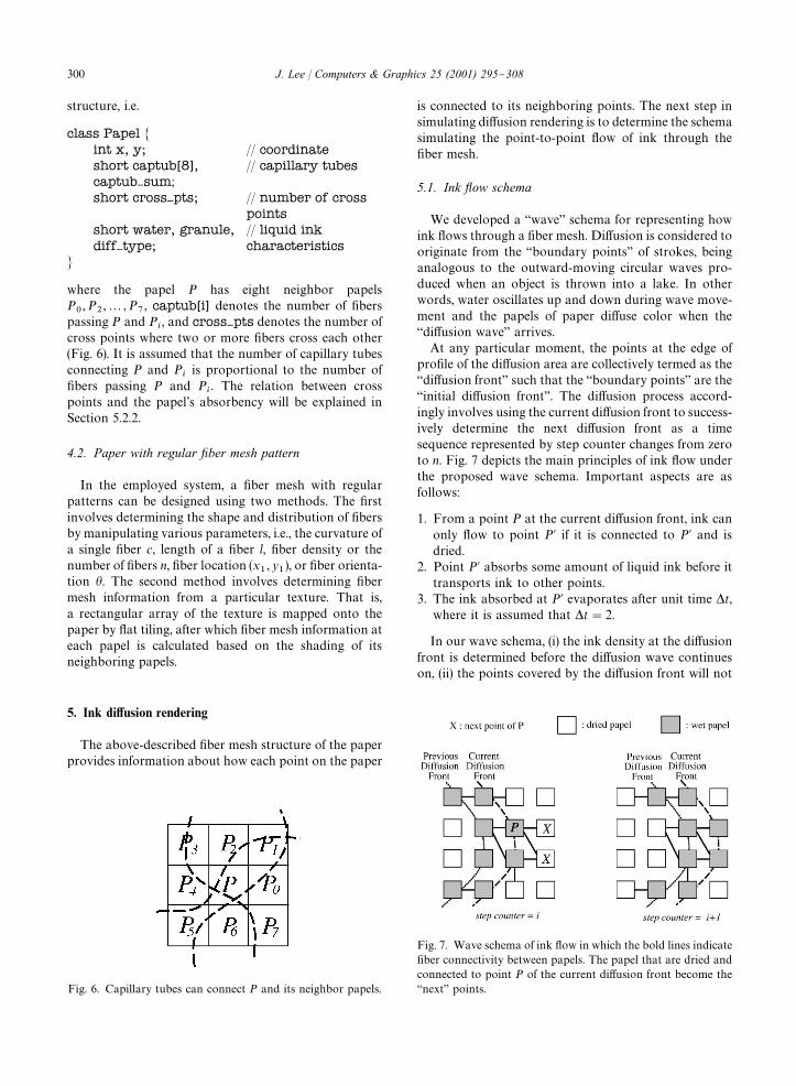
Fig. 6. Capillary tubes can connect P and its neighbor papels.
Fig. 7. Wave schema of ink #ow in which the bold lines indicate"ber connectivity between papels. The papel that are dried andconnected to point P of the current di!usion front become the`nexta points.
structure, i.e.
class Papel �int x, y; // coordinateshort captub[8],captub}sum;
// capillary tubes
short cross}pts; // number of crosspoints
short water, granule,diff}type;
// liquid inkcharacteristics
�
where the papel P has eight neighbor papelsP�, P
�,2, P
�, captub[i] denotes the number of "bers
passing P and P�, and cross}pts denotes the number of
cross points where two or more "bers cross each other(Fig. 6). It is assumed that the number of capillary tubesconnecting P and P
�is proportional to the number of
"bers passing P and P�. The relation between cross
points and the papel's absorbency will be explained inSection 5.2.2.
4.2. Paper with regular xber mesh pattern
In the employed system, a "ber mesh with regularpatterns can be designed using two methods. The "rstinvolves determining the shape and distribution of "bersby manipulating various parameters, i.e., the curvature ofa single "ber c, length of a "ber l, "ber density or thenumber of "bers n, "ber location (x
�, y
�), or "ber orienta-
tion �. The second method involves determining "bermesh information from a particular texture. That is,a rectangular array of the texture is mapped onto thepaper by #at tiling, after which "ber mesh information ateach papel is calculated based on the shading of itsneighboring papels.
5. Ink di4usion rendering
The above-described "ber mesh structure of the paperprovides information about how each point on the paper
is connected to its neighboring points. The next step insimulating di!usion rendering is to determine the schemasimulating the point-to-point #ow of ink through the"ber mesh.
5.1. Ink yow schema
We developed a `wavea schema for representing howink #ows through a "ber mesh. Di!usion is considered tooriginate from the `boundary pointsa of strokes, beinganalogous to the outward-moving circular waves pro-duced when an object is thrown into a lake. In otherwords, water oscillates up and down during wave move-ment and the papels of paper di!use color when the`di!usion wavea arrives.
At any particular moment, the points at the edge ofpro"le of the di!usion area are collectively termed as the`di!usion fronta such that the `boundary pointsa are the`initial di!usion fronta. The di!usion process accord-ingly involves using the current di!usion front to success-ively determine the next di!usion front as a timesequence represented by step counter changes from zeroto n. Fig. 7 depicts the main principles of ink #ow underthe proposed wave schema. Important aspects are asfollows:
1. From a point P at the current di!usion front, ink canonly #ow to point P� if it is connected to P� and isdried.
2. Point P� absorbs some amount of liquid ink before ittransports ink to other points.
3. The ink absorbed at P� evaporates after unit time �t,where it is assumed that �t"2.
In our wave schema, (i) the ink density at the di!usionfront is determined before the di!usion wave continueson, (ii) the points covered by the di!usion front will not
300 J. Lee / Computers & Graphics 25 (2001) 295}308
be included in the next di!usion front for a short periodof time; hence the number of points involved in thedi!usion process can only linearly increase over time,and (iii) the ink cannot #ow backward because the di!u-sion wave travels only outward. Moreover, the waveschema allows di!usion by overlapped strokes becauseink on prior strokes is considered to evaporate after a settime elapses.
5.2. Papel intensity decision schema
Regarding the di!usion rendering algorithm, theabove procedure was implemented such that the nextdi!usion front is determined from the current di!usionfront, while the color intensity of papels in the nextdi!usion front is determined from the color intensity ofpapels in the current di!usion front. In calculating theimage intensity of the di!usion image, two factors mustbe considered: (1) the global and continuous change ofintensity moving from the boundary of stroke toward theedge of di!usion image and (2) the local variance ofintensity. The "rst factor depends on a "ber's water-adhesive property, geometry of the "bers, mesh structure,density of liquid ink at the source points, and the value ofstep counter, whereas the second one depends on thelocal "ber density and the con"guration in which the"ber mesh is interlaced.
5.2.1. Global change of color intensityDirect observation of any di!usion image reveals that
the density of ink decreases during the di!usion processdue to the deposition of colloidal ink particles onto the"bers. However, since ink di!usion is a complex hy-drodynamic percolation phenomenon caused by absorb-ent "bers, mesh structure, and special characteristics ofthe ink, it is di$cult to formulate a mathematical equa-tion describing ink dynamics for a speci"c type ofpaper.
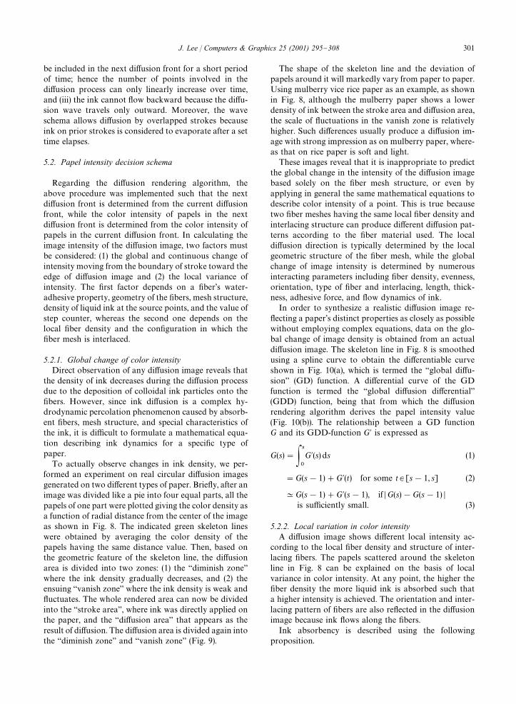
To actually observe changes in ink density, we per-formed an experiment on real circular di!usion imagesgenerated on two di!erent types of paper. Brie#y, after animage was divided like a pie into four equal parts, all thepapels of one part were plotted giving the color density asa function of radial distance from the center of the imageas shown in Fig. 8. The indicated green skeleton lineswere obtained by averaging the color density of thepapels having the same distance value. Then, based onthe geometric feature of the skeleton line, the di!usionarea is divided into two zones: (1) the `diminish zoneawhere the ink density gradually decreases, and (2) theensuing `vanish zonea where the ink density is weak and#uctuates. The whole rendered area can now be dividedinto the `stroke areaa, where ink was directly applied onthe paper, and the `di!usion areaa that appears as theresult of di!usion. The di!usion area is divided again intothe `diminish zonea and `vanish zonea (Fig. 9).
The shape of the skeleton line and the deviation ofpapels around it will markedly vary from paper to paper.Using mulberry vice rice paper as an example, as shownin Fig. 8, although the mulberry paper shows a lowerdensity of ink between the stroke area and di!usion area,the scale of #uctuations in the vanish zone is relativelyhigher. Such di!erences usually produce a di!usion im-age with strong impression as on mulberry paper, where-as that on rice paper is soft and light.
These images reveal that it is inappropriate to predictthe global change in the intensity of the di!usion imagebased solely on the "ber mesh structure, or even byapplying in general the same mathematical equations todescribe color intensity of a point. This is true becausetwo "ber meshes having the same local "ber density andinterlacing structure can produce di!erent di!usion pat-terns according to the "ber material used. The localdi!usion direction is typically determined by the localgeometric structure of the "ber mesh, while the globalchange of image intensity is determined by numerousinteracting parameters including "ber density, evenness,orientation, type of "ber and interlacing, length, thick-ness, adhesive force, and #ow dynamics of ink.
In order to synthesize a realistic di!usion image re-#ecting a paper's distinct properties as closely as possiblewithout employing complex equations, data on the glo-bal change of image density is obtained from an actualdi!usion image. The skeleton line in Fig. 8 is smoothedusing a spline curve to obtain the di!erentiable curveshown in Fig. 10(a), which is termed the `global di!u-siona (GD) function. A di!erential curve of the GDfunction is termed the `global di!usion di!erentiala(GDD) function, being that from which the di!usionrendering algorithm derives the papel intensity value(Fig. 10(b)). The relationship between a GD functionG and its GDD-function G� is expressed as
G(s)"��
�
G�(s) ds (1)
"G(s!1)#G�(t) for some t3[s!1, s] (2)
KG(s!1)#G�(s!1), if �G(s)!G(s!1) �is su$ciently small. (3)
5.2.2. Local variation in color intensityA di!usion image shows di!erent local intensity ac-
cording to the local "ber density and structure of inter-lacing "bers. The papels scattered around the skeletonline in Fig. 8 can be explained on the basis of localvariance in color intensity. At any point, the higher the"ber density the more liquid ink is absorbed such thata higher intensity is achieved. The orientation and inter-lacing pattern of "bers are also re#ected in the di!usionimage because ink #ows along the "bers.
Ink absorbency is described using the followingproposition.
J. Lee / Computers & Graphics 25 (2001) 295}308 301
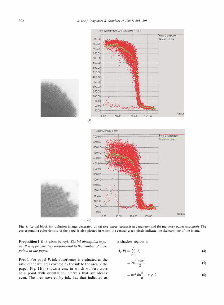
Fig. 8. Actual black ink di!usion images generated on (a) rice paper (gasenshi in Japanese) and (b) mulberry paper (kozoushi). Thecorresponding color density of the papel is also plotted in which the central green pixels indicate the skeleton line of the image.
Proposition 1 (Ink-absorbency). The ink absorption at pa-pel P is approximately proportional to the number of crosspoints in the papel.
Proof. For papel P, ink absorbency is evaluated as theratio of the wet area covered by the ink to the area of thepapel. Fig. 11(b) shows a case in which n "bers crossat a point with orientation intervals that are ideallyeven. The area covered by ink, i.e., that indicated as
a shadow region, is
A�(P)"
�����
S�
(4)
"2nr� sin �
2(5)
"nr� sin�
n, n*2. (6)
302 J. Lee / Computers & Graphics 25 (2001) 295}308
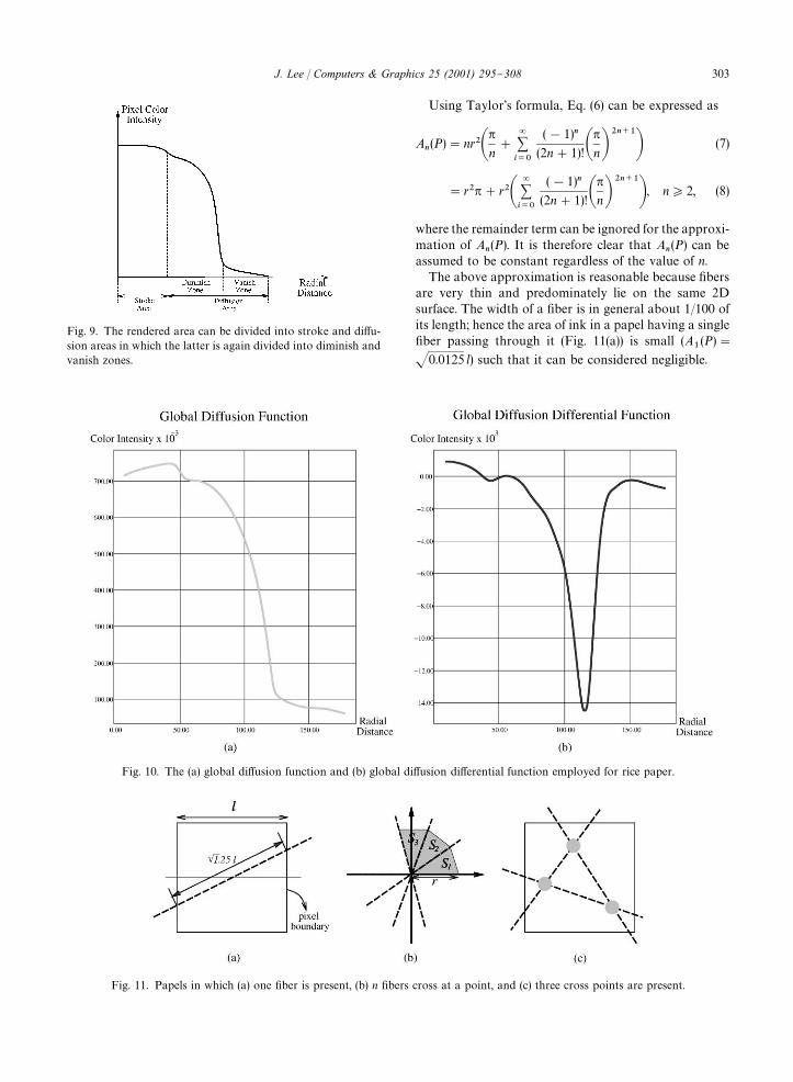
Fig. 9. The rendered area can be divided into stroke and di!u-sion areas in which the latter is again divided into diminish andvanish zones.
Fig. 10. The (a) global di!usion function and (b) global di!usion di!erential function employed for rice paper.
Fig. 11. Papels in which (a) one "ber is present, (b) n "bers cross at a point, and (c) three cross points are present.
Using Taylor's formula, Eq. (6) can be expressed as
A�(P)"nr��
�
n#
�����
(!1)�
(2n#1)!��
n�����
� (7)
"r��#r�������
(!1)�
(2n#1)!��
n�����
�, n*2, (8)
where the remainder term can be ignored for the approxi-mation of A
�(P). It is therefore clear that A
�(P) can be
assumed to be constant regardless of the value of n.The above approximation is reasonable because "bers
are very thin and predominately lie on the same 2Dsurface. The width of a "ber is in general about 1/100 ofits length; hence the area of ink in a papel having a single"ber passing through it (Fig. 11(a)) is small (A
�(P)"
�0.0125 l) such that it can be considered negligible.
J. Lee / Computers & Graphics 25 (2001) 295}308 303
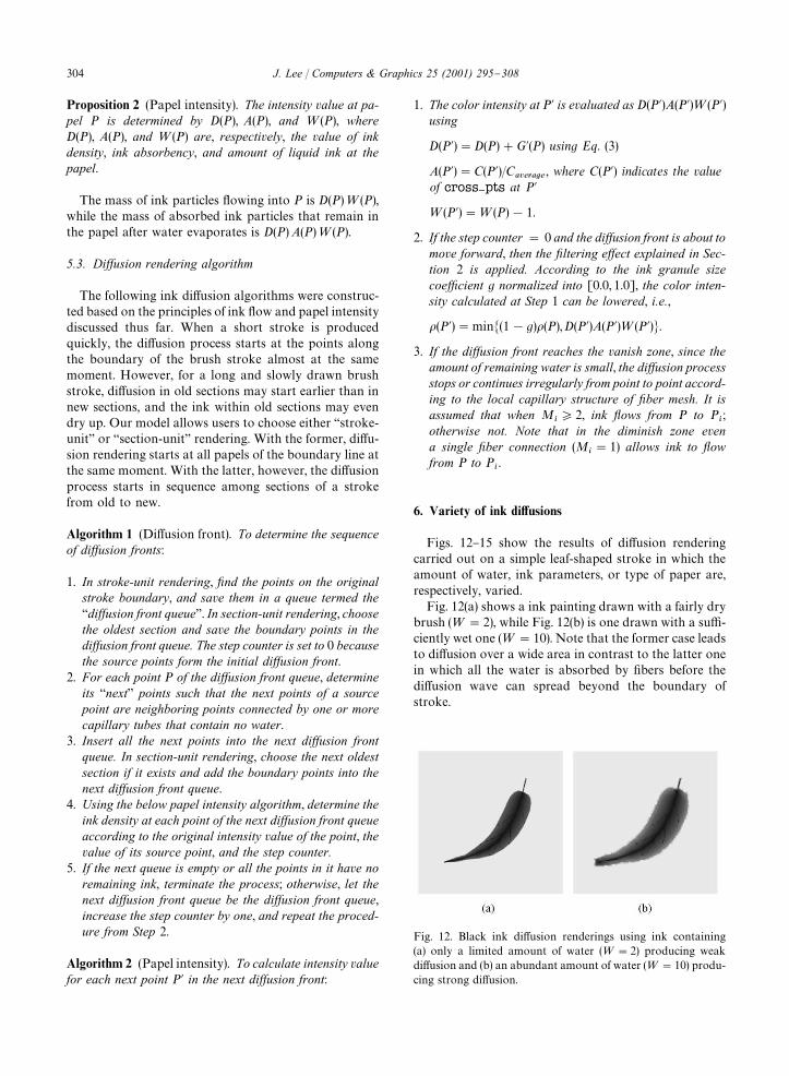
Fig. 12. Black ink di!usion renderings using ink containing(a) only a limited amount of water (="2) producing weakdi!usion and (b) an abundant amount of water (="10) produ-cing strong di!usion.
Proposition 2 (Papel intensity). The intensity value at pa-pel P is determined by D(P), A(P), and =(P), whereD(P), A(P), and =(P) are, respectively, the value of inkdensity, ink absorbency, and amount of liquid ink at thepapel.
The mass of ink particles #owing into P is D(P)=(P),while the mass of absorbed ink particles that remain inthe papel after water evaporates is D(P) A(P)=(P).
5.3. Diwusion rendering algorithm
The following ink di!usion algorithms were construc-ted based on the principles of ink #ow and papel intensitydiscussed thus far. When a short stroke is producedquickly, the di!usion process starts at the points alongthe boundary of the brush stroke almost at the samemoment. However, for a long and slowly drawn brushstroke, di!usion in old sections may start earlier than innew sections, and the ink within old sections may evendry up. Our model allows users to choose either `stroke-unita or `section-unita rendering. With the former, di!u-sion rendering starts at all papels of the boundary line atthe same moment. With the latter, however, the di!usionprocess starts in sequence among sections of a strokefrom old to new.
Algorithm 1 (Di!usion front). To determine the sequenceof diwusion fronts:
1. In stroke-unit rendering, xnd the points on the originalstroke boundary, and save them in a queue termed the`diwusion front queuea. In section-unit rendering, choosethe oldest section and save the boundary points in thediwusion front queue. The step counter is set to 0 becausethe source points form the initial diwusion front.
2. For each point P of the diwusion front queue, determineits `nexta points such that the next points of a sourcepoint are neighboring points connected by one or morecapillary tubes that contain no water.
3. Insert all the next points into the next diwusion frontqueue. In section-unit rendering, choose the next oldestsection if it exists and add the boundary points into thenext diwusion front queue.
4. Using the below papel intensity algorithm, determine theink density at each point of the next diwusion front queueaccording to the original intensity value of the point, thevalue of its source point, and the step counter.
5. If the next queue is empty or all the points in it have noremaining ink, terminate the process; otherwise, let thenext diwusion front queue be the diwusion front queue,increase the step counter by one, and repeat the proced-ure from Step 2.
Algorithm 2 (Papel intensity). To calculate intensity valuefor each next point P� in the next diwusion front:
1. The color intensity at P� is evaluated as D(P�)A(P�)=(P�)using
D(P�)"D(P)#G�(P) using Eq. (3)
A(P�)"C(P�)/C������
, where C(P�) indicates the valueof cross}pts at P�
=(P�)"=(P)!1.
2. If the step counter " 0 and the diwusion front is about tomove forward, then the xltering ewect explained in Sec-tion 2 is applied. According to the ink granule sizecoezcient g normalized into [0.0, 1.0], the color inten-sity calculated at Step 1 can be lowered, i.e.,
�(P�)"min�(1!g)�(P), D(P�)A(P�)=(P�)�.
3. If the diwusion front reaches the vanish zone, since theamount of remaining water is small, the diwusion processstops or continues irregularly from point to point accord-ing to the local capillary structure of xber mesh. It isassumed that when M
�*2, ink yows from P to P
�;
otherwise not. Note that in the diminish zone evena single xber connection (M
�"1) allows ink to yow
from P to P�.
6. Variety of ink di4usions
Figs. 12}15 show the results of di!usion renderingcarried out on a simple leaf-shaped stroke in which theamount of water, ink parameters, or type of paper are,respectively, varied.
Fig. 12(a) shows a ink painting drawn with a fairly drybrush (="2), while Fig. 12(b) is one drawn with a su$-ciently wet one (="10). Note that the former case leadsto di!usion over a wide area in contrast to the latter onein which all the water is absorbed by "bers before thedi!usion wave can spread beyond the boundary ofstroke.
304 J. Lee / Computers & Graphics 25 (2001) 295}308
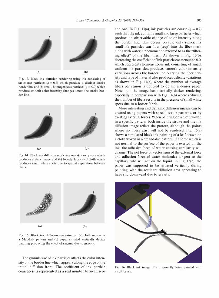
Fig. 13. Black ink di!usion rendering using ink consisting of(a) coarse particles (g"0.7) which produce a distinct strokeborder line and (b) small, homogeneous particles (g"0.0) whichproduce smooth color intensity changes across the stroke bor-der line.
Fig. 14. Black ink di!usion rendering on (a) dense paper whichproduces a dark image and (b) loosely fabricated cloth whichproduces small white spots due to spatial separation between"bers.
Fig. 15. Black ink di!usion rendering on (a) cloth woven ina Mandala pattern and (b) paper situated vertically duringpainting producing the e!ect of sagging due to gravity.
Fig. 16. Black ink image of a dragon #y being painted witha soft brush.
The granule size of ink particles a!ects the color inten-sity of the border line which appears along the edge of theinitial di!usion front. The coe$cient of ink particlecoarseness is represented as a real number between zero
and one. In Fig. 13(a), ink particles are coarse (g"0.7)such that the ink contains small and large particles whichproduce an observable change of color intensity alongthe border line. This occurs because only su$cientlysmall ink particles can #ow (seep) into the "ber meshalong with water; a phenomenon referred to as the `"lter-ing e!ecta of the "ber mesh. As shown in Fig. 13(b),decreasing the coe$cient of ink particle coarseness to 0.0,which represents homogeneous ink consisting of small,uniform ink particles, produces smooth color intensityvariations across the border line. Varying the "ber den-sity and type of material also produces delicate variationsas shown in Fig. 14(a), where the number of average"bers per region is doubled to obtain a denser paper.Note that the image has markedly darker rendering,especially in comparison with Fig. 14(b) where reducingthe number of "bers results in the presence of small whitespots due to a looser fabric.
More interesting and dynamic di!usion images can becreated using papers with special textile patterns, or byexerting external forces. When painting on a cloth wovenin a speci"c pattern, both inside the stroke and the inkdi!usion image re#ect the pattern, although the pointswhere no "bers exist will not be rendered. Fig. 15(a)shows a simulated black ink painting of a leaf drawn ona cloth woven in a `mandalaa pattern. If a force which isnot normal to the surface of the paper is exerted on theink, the adhesive force of water causing capillarity willchange. The net force or vector sum of the external forceand adhesion force of water molecules tangent to thecapillary tube will act on the liquid. In Fig. 15(b), thepaper was supposed to be situated vertically duringpainting, with the resultant di!usion area appearing tohave slid downward due to gravity.
J. Lee / Computers & Graphics 25 (2001) 295}308 305
306 J. Lee / Computers & Graphics 25 (2001) 295}308
�&&&&&&&&&&&&&&&&&&&&&&&&&&&
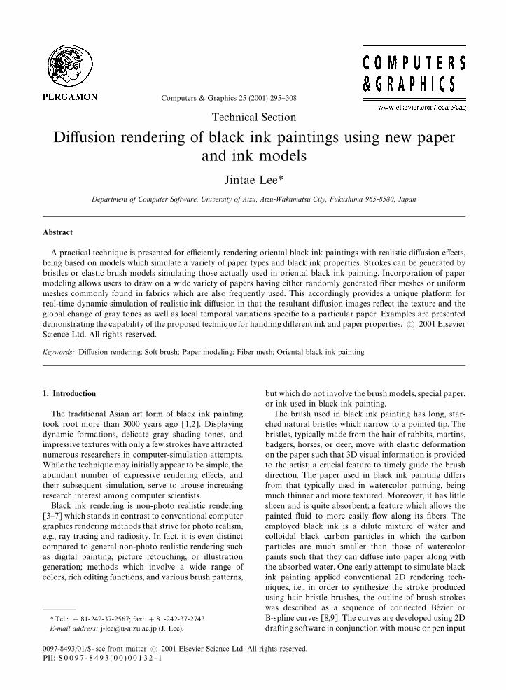
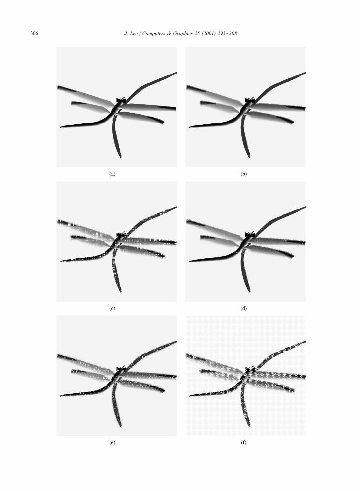
Fig. 17. Dragon #y di!usion image painted on (a) egg paper,(b) rice paper, (c) yam cloth, (d) silk cloth, (e) cloth woven ina leather pattern, and (f) cloth woven in a #ower pattern.
7. Discussion
The described di!usion rendering technique generatesrealistic di!usion images using models that account for"ber mesh structured paper and ink #ow. These tech-niques allow computer simulating black ink painting andcalligraphy, as well as rendering general graphic imageswhen combined with an edge detection algorithm. Al-though the proposed method can be applied to anyexisting painting system, it is considered most e!ectivewhen brush strokes are generated using a soft brush.
Fig. 16 shows a simulated black ink painting ofa dragon #y generated using a soft brush, while Fig. 17shows corresponding simulations generated by applyingour di!usion rendering method using several paper mod-els. Note the remarkable di!erences solely due to varyingthe paper type. The body of the dragon #y was drawnwith ink containing only a limited amount of water,whereas the wings were drawn using ink containingabundant amount of water such that they more visiblyshow di!usion e!ects. In addition, at the end of the wingswhere two strokes overlap, the image shows a realisticcombination of di!usion intensity, being obtained bycalculating the background and foreground image inten-sity. The right wings drawn with an abundant amount ofwater are controlled to lighten the color intensity of thebody; thereby showing the correct perspective relation-ship between the objects.
The proposed ink di!usion rendering method pos-sesses several computational merits, i.e.,
� The user can select from a wide variety of papertextures consisting of randomly distributed "ber meshand uniform fabric mesh.
� The computational complexity of wave schema is lin-ear: O(n).
� Realistic di!usion images are generated by consideringboth the global change and local variance of imageintensity peculiar to the selected paper type.
� When coupled with the soft brush [17], all operationssuch as inputting of strokes, selecting paper type, andspecifying parameter values can be carried out interac-tively and naturally, without editing 2D controlpoints.
Drawing the di!usion image of the dragon #y painting(Fig. 17) took an average of just 5 s using a SGI O2system; a speed su$cient for users to believe that di!u-sion occurs in real time. Such reasonable performance isdue to the employed #ow schema that works in lineartime by preventing ink from #owing backward.
One general rule in actual oriental black ink paintingis that strokes are performed only once, i.e., there can beno later altering, touching up, or adding to them; unlikeoil painting where mistakes may be scraped o! orpainted over. With computer-based painting, however,painters can try the same brush stroke as many times asneeded to obtain the proper e!ect, and doing so withoutwasting paper. When considering that a single improperstroke can ruin an entire painting, this advantage isespecially bene"cial.
There exist other interesting rendering e!ects in blackink painting that have not been discussed here. Onenotable feature is scratchiness (kasure in Japanese), beingthe white scratchy texture displayed when the brushmoves fast or the ink runs out in the middle of a stroke.This feature is a!ected by many physical factors such aspressure applied on the brush, speed of moving a brush,and the roughness of the paper surface. Development ofrequired physical models and algorithms is left for futureresearch.
References
[1] Thompson K, Uchiyama U. The art and technique ofSumi-e. Tokyo: Charles E. Tuttle Co., Inc., 1960.
[2] Saito R, Japanese ink-painting. Tokyo: Charles E. TuttleCo., Inc., 1959.
[3] Lansdown J, Scho"eld S. Expressive rendering: a review ofnonphotorealistic techniques. IEEE Computer Graphics& Applications 1995;15(3):29}37.
[4] Hsu S, Lee I. Drawing and animation using skeletalstrokes. Computer Graphics, Annual Conference Series(Proceedings of the SIGGRAPH 94). New York: ACM,1994. p. 109}18.
[5] Winkenbach G, Salesin DH. Computer-generated pen-and ink illustration. Proceedings of the SIGGRAPH 94.New York: ACM, 1994. p. 91}100.
[6] Winkenbach G, Salesin DH. Rendering parametric surfa-ces in pen and ink. Proceedings of the SIGGRAPH 96.New York: ACM, 1996. p. 469}76.
[7] Markosian L. Real-time nonphotorealistic rendering.Proceedings of the SIGGRAPH 97. New York: ACM,1997. p. 414}20.
[8] Chua Y. BeH zier brushstrokes. Computer Aided Design1990;22(9):550}5.
[9] Nishita T, Takita S, Nakamae E. A display algorithm ofbrush strokes using beH zier functions. In: Thalmann N,Thalmann D, editors. Communicating with VirtualWorlds (Proceedings of the CGI'93). Berlin: Springer,1993. p. 244}57.
[10] Haeberli P. Paint by numbers: abstract image representa-tions. Computer Graphics 1992;24(4):207}14.
[11] Curtis CJ. Computer-generated watercolor. Proceedingsof the SIGGRAPH 97. New York: ACM, 1997. p. 421}30.
[12] Greenberg A, Greenberg S. The ultimate guide to fractaldesign painter. Alameda: SYBEX Inc., 1995.
[13] Strassmann S. Hairy brushes. Computer Graphics1986;20(4):225}32.
J. Lee / Computers & Graphics 25 (2001) 295}308 307
[14] Zhang Q, Sato Y, Takahashi J, Muraoka K, Chiba N.Simple cellular automaton-based simulation of ink behav-iour and its application to suibokuga-like 3d rendering oftrees. Journal of Visualization and Computer Animation1999;10:15}26.
[15] Greene R. The drawing prism: a versatile graphic inputdevice. Proceedings of the SIGGRAPH 85. New York:ACM, 1985. p. 103}10.
[16] Pang Y, Zhong H. Drawing chinese traditional paintingby computer, In: Kunii T, editor. Modeling in computergraphics (Proceedings of the IFIP WG5.10). Berlin:Springer, 1991. p. 321}8.
[17] Lee J. Simulating oriental black-ink painting. IEEE Com-puter Graphics & Applications 1999;19(3):74}81.
[18] Guo Q, Kunii T. Modeling the di!use painting of &sumie'. In:Kunii T, editor. Modeling in computer graphics (Proceedingsof the IFIP WG5.10). Berlin: Springer, 1991. p. 329}38.
[19] Landau L, Lifshitz E. Fluid mechanics, Course of theor-etical physics, vol. 6, 2nd ed. Oxford: Pergamon Press,1987.
[20] Serway R. Physics for scientists and engineers with mod-ern physics, 3rd ed. Philadelphia: Saunders CollegePublishing, 1990.
[21] Kallmes O, Corte H. The structure of paper in, the statist-ical geometry of an ideal two dimensional "ber network.Tappi Journal 1960;43(9):737}52.
[22] Rance H. Handbook of paper science, vol. 2. Amsterdam:Elsevier, 1982.
[23] Yang W. Computer animation of dynamic stochastic"bre networks. PhD thesis, Dept. of Chemical Engineeringand Applied Chemistry, University of Toronto, Canada,1995.
[24] Kobayashi T. Introduction to Sumie painting. Tokyo:Graphics Ltd., 1991.
308 J. Lee / Computers & Graphics 25 (2001) 295}308