Embed Size (px)
Citation preview
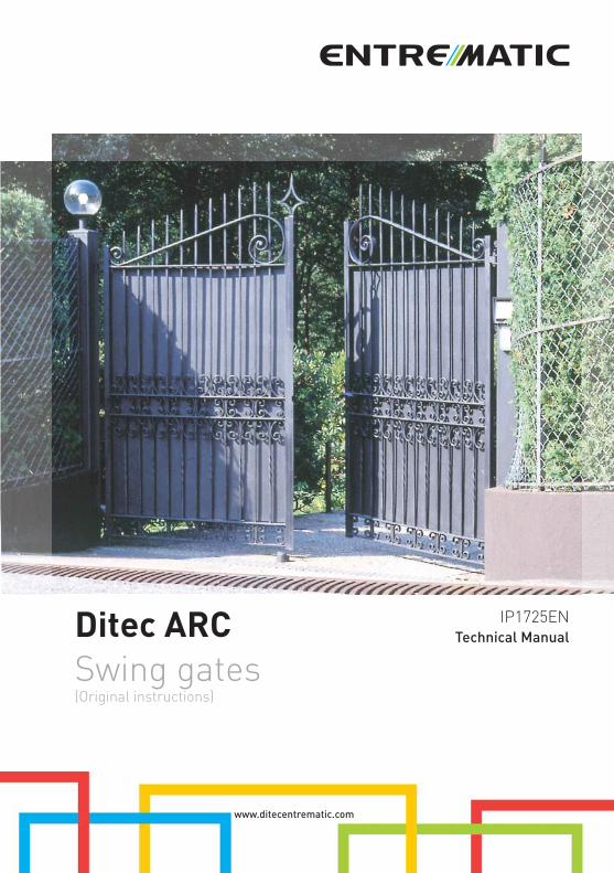
Ditec ARCSwing gates(Original instructions)
www.ditecentrematic.com
IP1725EN
Technical Manual

20
IP1
72
5E
N -
20
15
-05
-14
All the rights concerning this material are the exclusive property of Entrematic Group AB. Although the con-
tents of this publication have been drawn up with the greatest care, Entrematic Group AB cannot be held
responsible in any way for any damage caused by mistakes or omissions in this publication.
We reserve the right to make changes without prior notice. Copying, scanning and changing in any way are
expressly forbidden unless authorised in writing by Entrematic Group AB.
21
IP1
72
5E
N -
20
15
-05
-14
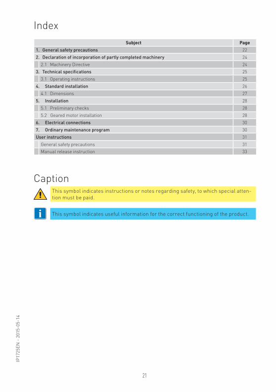
Subject Page1. General safety precautions 22
2. Declaration of incorporation of partly completed machinery 24
2.1 Machinery Directive 24
3. Technical specifications 25
3.1 Operating instructions 25
4. Standard installation 26
4.1 Dimensions 27
5. Installation 28
5.1 Preliminary checks 28
5.2 Geared motor installation 28
6. Electrical connections 30
7. Ordinary maintenance program 30
User instructions 31
General safety precautions 31
Manual release instruction 33
Caption
Index
i
This symbol indicates instructions or notes regarding safety, to which special atten-
tion must be paid.
This symbol indicates useful information for the correct functioning of the product.
22
IP1
72
5E
N -
20
15
-05
-14
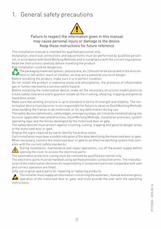
1. General safety precautions
This installation manual is intended for qualified personnel only.
Installation, electrical connections and adjustments must be performed by qualified person-
nel, in accordance with Good Working Methods and in compliance with the current regulations.
Read the instructions carefully before installing the product.
Bad installation could be dangerous.
The packaging materials (plastic, polystyrene, etc.) should not be discarded in the environ-
ment or left within reach of children, as they are a potential source of danger.
Before installing the product, make sure it is in perfect condition.
Do not install the product in explosive areas and atmospheres: the presence of inflammable
gas or fumes represents a serious safety hazard.
Before installing the motorisation device, make all the necessary structural modifications to
create safety clearance and to guard or isolate all the crushing, shearing, trapping and general
hazardous areas.
Make sure the existing structure is up to standard in terms of strength and stability. The mo-
torisation device manufacturer is not responsible for failure to observe Good Working Methods
when building the frames to be motorised, or for any deformation during use.
The safety devices (photocells, safety edges, emergency stops, etc.) must be installed taking into
account: applicable laws and directives, Good Working Methods, installation premises, system
operating logic and the forces developed by the motorised door or gate.
The safety devices must protect against crushing, cutting, trapping and general danger areas
of the motorised door or gate.
Display the signs required by law to identify hazardous areas.
Each installation must bear a visible indication of the data identifying the motorised door or gate.
When necessary, connect the motorised door or gate to an effective earthing system that com-
plies with the current safety standards.
During installation, maintenance and repair operations, cut off the power supply before
opening the cover to access the electrical parts.
The automation protection casing must be removed by qualified personnel only.
The electronic parts must be handled using earthed antistatic conductive arms. The manufac-
turer of the motorisation declines all responsibility if component parts not compatible with safe
and correct operation are fitted.
Only use original spare parts for repairing or replacing products.
The installer must supply all information concerning the automatic, manual and emergency
operation of the motorised door or gate, and must provide the user with the operating
instructions.
Failure to respect the information given in this manualmay cause personal injury or damage to the device.
Keep these instructions for future reference
23
IP1
72
5E
N -
20
15
-05
-14
These precautions are an integral and essential part of the product and
must be supplied to the user.
Read them carefully since they contain important information on safe instal-
lation, use and maintenance.
These instructions must be kept and forwarded to all possible future users
of the system. This product must only be used for the specific purpose for
which it was designed.
Any other use is to be considered improper and therefore dangerous. The
manufacturer cannot be held responsible for any damage caused by improper,
incorrect or unreasonable use.
Avoid operating in the proximity of the hinges or moving mechanical parts.
Do not enter within the operating range of the motorised door or gate while
it is moving.
Do not obstruct the motion of the motorised door or gate, as this may cause
a dangerous situation.
The motorised door or gate may be used by children over the age of 8 and by
people with reduced physical, sensorial or mental abilities, or lack of expe-
rience or knowledge, as long as they are properly supervised or have been
instructed in the safe use of the device and the relative hazards.
Children must be supervised to make sure they do not play with the device,
nor play/remain in the sphere of action of the motorised door or gate.
Keep remote controls and/or any other command devices out of the reach
of children, to avoid any accidental activation of the motorised door or gate.
In the event of a product fault or malfunction, turn off the power supply switch.
Do not attempt to repair or intervene directly, and contact only qualified per-
sonnel. Failure to comply with the above may cause a dangerous situation.
Any repair or technical intervention must be carried out by qualified personnel.
Cleaning and maintenance work must not be carried out by children unless
they are supervised.
To ensure that the system works efficiently and correctly, the manufacturer’s
indications must be complied with and only qualified personnel must perform
routine maintenance on the motorised door or gate. In particular, regular
checks are recommended in order to verify that the safety devices are oper-
ating correctly.
All installation, maintenance and repair work must be documented and made
available to the user.
Only lock and release the door wings when the motor is switched off. Do not
enter within the operating range of the wing.
To dispose of electrical and electronic equipment correctly, users must
take the product to special “recycling centres” provided by the municipal
authorities.
General safety precautions for the user
24
IP1
72
5E
N -
20
15
-05
-14
(Directive 2006/42/EC, Annex II-B)
The manufacturer Entrematic Group AB, with headquarters in Lodjursgatan 10, SE-261 44 Land-
skrona, Sweden, declares that the automation for swing gates type Ditec ARC:
- is designed to be installed on a manual gate to form a machine pursuant to Directive 2006/42/
EC. The manufacturer of the motorised gate must declare conformity with Directive 2006/42/
EC (annex II-A) prior to initial machine start-up;
- conforms to the applicable essential safety requirements indicated in ANNEX I, Chapter 1 of the
Directive 2006/42/EC;
- conforms to the Low Voltage Directive 2006/95/EC;
- conforms to the Electromagnetic Compatibility Directive 2004/108/EC:
- conforms to the R&TTE Directive 1999/5/EC;
- the technical documentation conforms to Annex VII-B of the Directive 2006/42/EC;
- the technical documentation is managed by Marco Pietro Zini with headquarters in Via Mons.
Banfi, 3 - 21042 Caronno Pertusella (VA) - ITALY;
- a copy of technical documentation will be provided to national competent authorities, following
a suitably justified request.
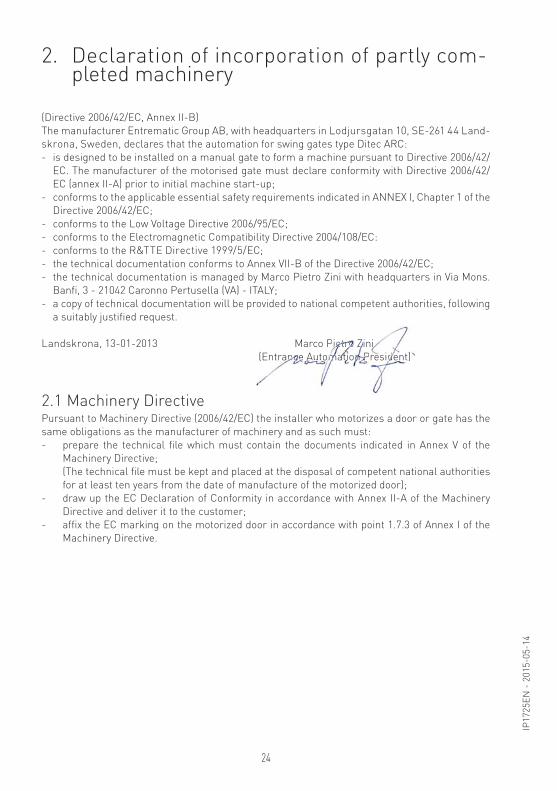
Landskrona, 13-01-2013 Marco Pietro Zini
(Entrance Automation President)
2.1 Machinery DirectivePursuant to Machinery Directive (2006/42/EC) the installer who motorizes a door or gate has the
same obligations as the manufacturer of machinery and as such must:
- prepare the technical file which must contain the documents indicated in Annex V of the
Machinery Directive;
(The technical file must be kept and placed at the disposal of competent national authorities
for at least ten years from the date of manufacture of the motorized door);
- draw up the EC Declaration of Conformity in accordance with Annex II-A of the Machinery
Directive and deliver it to the customer;
- affix the EC marking on the motorized door in accordance with point 1.7.3 of Annex I of the
Machinery Directive.
2. Declaration of incorporation of partly com- pleted machinery
Marco Pietietietetiettetttetttttetttttttttttetttttettttetetetetteeeettttttteteeeeeeeeettieteeeeeeeeteeeeeeeieeeeeeeeeeeeeeeeieeeeeeeeeeeeeeeeeeeeeeeeeeieeeeeeeeeeeee rororororrorooorororrrrrrrooooooooooooororrrrrororrrroooorooooorrrrrrrrrrrooooororrrororrrooooorrrrroroooooooooooooooooooooooooooooooooooooooooooooooooooooroooooooooo ZinZinZiZiZiZiZiZZZZZZZZZZZZZZZZZZZZZZZZZZZZZZZZZZZZZZZZZZZZZZZZZZZ i
(Entranannannnnnnnnnnnnnnnnnnnnnnnnnnnnnnnnnnnnnnnnnnnnnnnnnnnnnnnnncececececececccccceccccccccecccccccccccecccccccccccccccccccccccccccccccccccccccccccccccccccccccccccccccccccccccecccceeeccceceeeeeecccceeeeeeececccceeceeeeeeee AutAuAuAAutAutAuAAAAutAAAAAAAAutAuttomaomammomammmamamammmommmmmomamaaammmamammmaammmmmmmamaaaaomammmmmaaaammmmmmmaaaaammmmmaaaaammmmmaaammmmmaaaamammaaaammmmmmmmaaaammmmmaammmmmmmmmmmmmmmmmmmmmmmmmmmm tiotioititiotitiotioiiitiiiitttttiiiitttiiittiitiottttittittti n Pn Pn Pn n Pn Pn nnnnnn Pnn Pn Pn n nnnnnnnnnn Pn Pnnnnnnnnn Pnnnnnnnnnnnnnnnnnnnnnnn Pnnnnnnnnn Pnnnnnnnnn PPPnnnnnnnn Pn PPPnnnnnnnnn PPPn Pnnnnnn PPPn Pnnn PPPnn PPPPnnn Pnnnn Pnnnnnnnnnnnnnn resresrrr ideideddedededededededededddddedddddedddddedddddedddddeddddddddddddddddddddddddddddddd nt)ntnnn
25
IP1
72
5E
N -
20
15
-05
-14
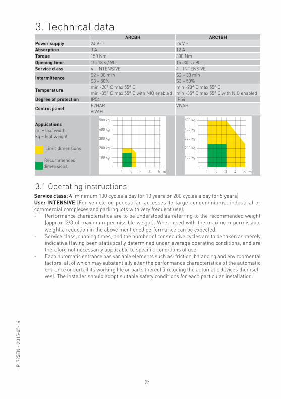
ARCBH ARC1BHPower supply 24 V 24 V
Absorption 3 A 12 A
Torque 150 Nm 300 Nm
Opening time 15÷18 s / 90° 15÷30 s / 90°
Service class 4 - INTENSIVE 4 - INTENSIVE
IntermittenceS2 = 30 min
S3 = 50%
S2 = 30 min
S3 = 50%
Temperaturemin -20° C max 55° C
min -35° C max 55° C with NIO enabled
min -20° C max 55° C
min -35° C max 55° C with NIO enabled
Degree of protection IP54 IP54
Control panelE2HAR
VIVAH
VIVAH
Applicationsm = leaf width
kg = leaf weight
Limit dimensions
Recommended
dimensions
500 kg
400 kg
300 kg
200 kg
100 kg
m1 2 3 4 5
500 kg
400 kg
300 kg
200 kg
100 kg
m1 2 3 4 5
Service class: 4 (minimum 100 cycles a day for 10 years or 200 cycles a day for 5 years)
Use: INTENSIVE (For vehicle or pedestrian accesses to large condominiums, industrial or
commercial complexes and parking lots with very frequent use).
- Performance characteristics are to be understood as referring to the recommended weight
(approx. 2/3 of maximum permissible weight). When used with the maximum permissible
weight a reduction in the above mentioned performance can be expected.
- Service class, running times, and the number of consecutive cycles are to be taken as merely
indicative Having been statistically determined under average operating conditions, and are
therefore not necessarily applicable to specifi c conditions of use.
- Each automatic entrance has variable elements such as: friction, balancing and environmental
factors, all of which may substantially alter the performance characteristics of the automatic
entrance or curtail its working life or parts thereof (including the automatic devices themsel-
ves). The installer should adopt suitable safety conditions for each particular installation.
3. Technical data
3.1 Operating instructions
26
IP1
72
5E
N -
20
15
-05
-14
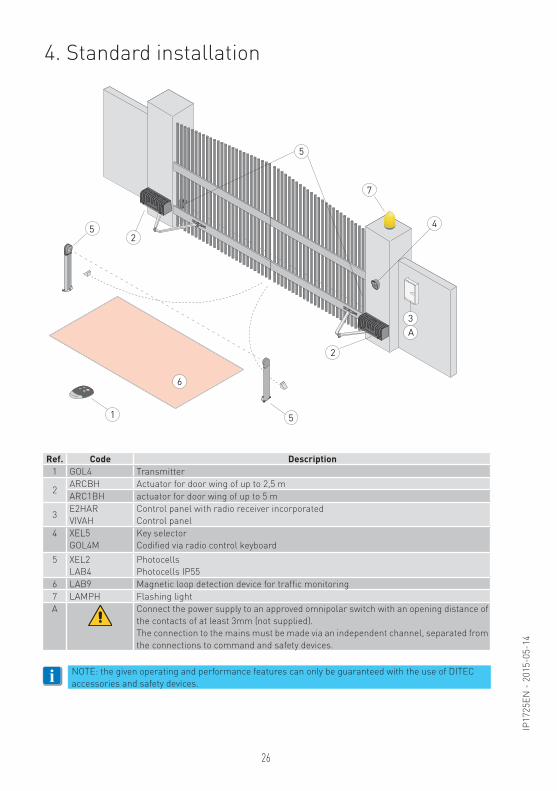
Ref. Code Description1 GOL4 Transmitter
2ARCBH Actuator for door wing of up to 2,5 m
ARC1BH actuator for door wing of up to 5 m
3E2HAR
VIVAH
Control panel with radio receiver incorporated
Control panel
4 XEL5
GOL4M
Key selector
Codified via radio control keyboard
5 XEL2
LAB4
Photocells
Photocells IP55
6 LAB9 Magnetic loop detection device for traffic monitoring
7 LAMPH Flashing light
A Connect the power supply to an approved omnipolar switch with an opening distance of
the contacts of at least 3mm (not supplied).
The connection to the mains must be made via an independent channel, separated from
the connections to command and safety devices.
i
4. Standard installation
1
6
52
2
3
4
7
5
A
5
NOTE: the given operating and performance features can only be guaranteed with the use of DITEC
accessories and safety devices.
27
IP1
72
5E
N -
20
15
-05
-14
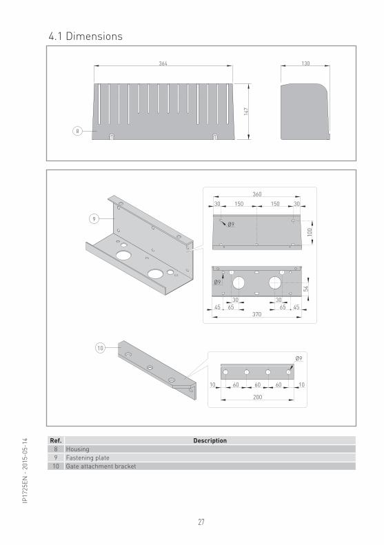
4.1 Dimensions
364
8
130
14
7
360
10
0
30 30150 150
Ø9
Ø9
45 455
465 65
370
30 30
9
Ref. Description8 Housing
9 Fastening plate
10 Gate attachment bracket
Ø9
200
60 60 1010 60
10
28
IP1
72
5E
N -
20
15
-05
-14
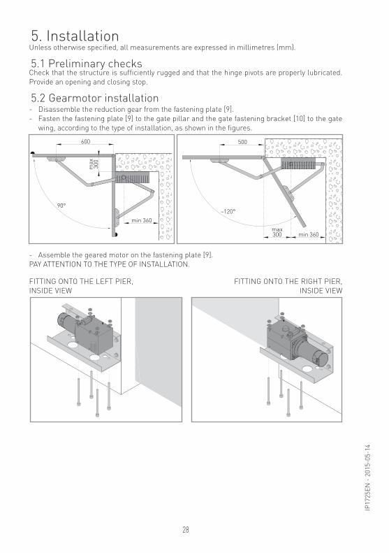
5. Installation
5.1 Preliminary checks
Unless otherwise specified, all measurements are expressed in millimetres (mm).
Check that the structure is sufficiently rugged and that the hinge pivots are properly lubricated.
Provide an opening and closing stop.
- Disassemble the reduction gear from the fastening plate [9].
- Fasten the fastening plate [9] to the gate pillar and the gate fastening bracket [10] to the gate
wing, according to the type of installation, as shown in the figures.
- Assemble the geared motor on the fastening plate [9].
PAY ATTENTION TO THE TYPE OF INSTALLATION.
FITTING ONTO THE LEFT PIER,
INSIDE VIEW
FITTING ONTO THE RIGHT PIER,
INSIDE VIEW
600
90°
min 360
ma
x3
00
~120°
500
max300 min 360
5.2 Gearmotor installation
29
IP1
72
5E
N -
20
15
-05
-14
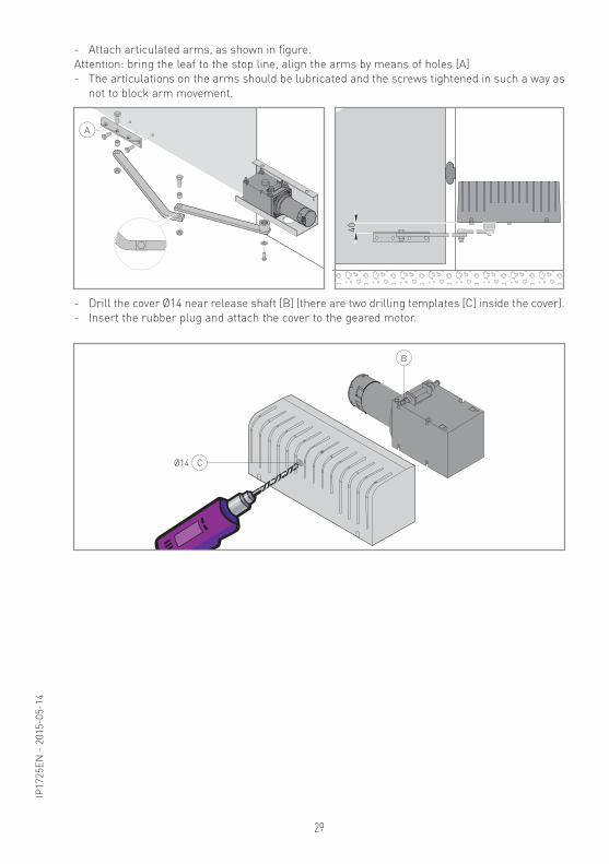
- Attach articulated arms, as shown in figure.
Attention: bring the leaf to the stop line, align the arms by means of holes [A]
- The articulations on the arms should be lubricated and the screws tightened in such a way as
not to block arm movement.
- Drill the cover Ø14 near release shaft [B] (there are two drilling templates [C] inside the cover).
- Insert the rubber plug and attach the cover to the geared motor.
A
40
CØ14
B
30
IP1
72
5E
N -
20
15
-05
-14
Perform the following operations and checks every 6 months according to intensity of use of the
automation.
Without 230 V~ power supply and batteries if present:
- Lubricate the levers of the gearmotor.
- Lubricate the rotation pivot of the gate leaf.
- Lubricate the gate leaf hinges.
- Check the good conditions of the electric connection.
- Check that the fixing screws of the gearmotor are firmly tightened.
Reconnect the 230 V~ power supply and batteries if present:
- Check the power adjustment.
- Check the good operation of all command and safety functions (photocells).
- Check the good operation of the release system.
i
6. Electrical connections
7. Routine maintenance plan
Before connecting the power supply, make sure the plate data correspond to that of the mains
power supply.
An omnipolar disconnection switch with minimum contact gaps of 3 mm must be included in the
mains supply.
Check that upstream of the electrical installation there is an adequate residual current circuit
breaker and a suitable overcurrent cutout.
The electrical connections and starting of the ARC gearmotor are illustrated in the E2HAR and
VIVAH control panel installation manual.
To reverse the direction of rotation, exchange the motor phases.
WARNING: For spare parts, see the spares price list.
31
IP1
72
5E
N -
20
15
-05
-14
Operating instructions
General safety precautions for the user
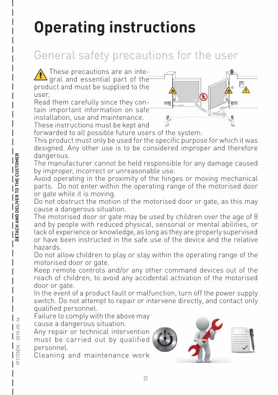
These precautions are an inte-gral and essential part of the
product and must be supplied to the user.Read them carefully since they con-tain important information on safe installation, use and maintenance.These instructions must be kept and forwarded to all possible future users of the system. This product must only be used for the specific purpose for which it was designed. Any other use is to be considered improper and therefore dangerous. The manufacturer cannot be held responsible for any damage caused by improper, incorrect or unreasonable use.Avoid operating in the proximity of the hinges or moving mechanical parts. Do not enter within the operating range of the motorised door or gate while it is moving.Do not obstruct the motion of the motorised door or gate, as this may cause a dangerous situation. The motorised door or gate may be used by children over the age of 8 and by people with reduced physical, sensorial or mental abilities, or lack of experience or knowledge, as long as they are properly supervised or have been instructed in the safe use of the device and the relative hazards.Do not allow children to play or stay within the operating range of the motorised door or gate.Keep remote controls and/or any other command devices out of the reach of children, to avoid any accidental activation of the motorised door or gate.In the event of a product fault or malfunction, turn off the power supply switch. Do not attempt to repair or intervene directly, and contact only qualified personnel.Failure to comply with the above may cause a dangerous situation.Any repair or technical intervention must be carried out by qualified personnel.Cleaning and maintenance work
DET
ACH
AN
D D
ELIV
ER T
O T
HE
CUST
OM
ER
32
IP1
72
5E
N -
20
15
-05
-14
DET
ACH
AN
D D
ELIV
ER T
O T
HE
CUST
OM
ER
must not be carried out by children unless they are supervised. To ensure that the system works efficiently and correctly, the manufac-turer’s indications must be complied with and only qualified personnel must perform routine maintenance on the motorised door or gate. In particular, regular checks are recommended in order to verify that the safety devices are operating correctly.All installation, maintenance and repair work must be documented and made available to the user.Only lock and release the door wings when the motor is switched off. Do not enter within the operating range of the wing.To dispose of electrical and electronic equipment correctly, users must
take the product to special “recycling centres” provided by the municipal authorities.
33
IP1
72
5E
N -
20
15
-05
-14
For any problems and/or information, contact the Technical Service.
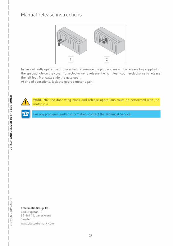
Manual release instructions
WARNING: the door wing block and release operations must be performed with the
motor idle.
Entrematic Group AB
Lodjursgatan 10
SE-261 44, Landskrona
Sweden
www.ditecentrematic.com
1 2
In case of faulty operation or power failure, remove the plug and insert the release key supplied in
the special hole on the cover. Turn clockwise to release the right leaf; counterclockwise to release
the left leaf. Manually slide the gate open.
At end of operations, lock the geared motor again.
DET
ACH
AN
D D
ELIV
ER T
O T
HE
CUST
OM
ER
IP1
72
5E
N -
20
15
-05
-14
Entrematic Group AB
Lodjursgatan 10
SE-261 44, Landskrona
Sweden
www.ditecentrematic.com