Embed Size (px)
Citation preview

Kirill Eliseev
DISTRICT HEATING SYSTEMS IN FINLAND AND RUSSIA
Bachelor Thesis Building Services
March 2011

Date of the bachelor's thesis
Author(s)
Kirill Eliseev
Degree programme and option
Building services
Name of the bachelor's thesis
District heating systems in Finland and Russia
Abstract
The subject of this thesis is the examination of district heating (DH) systems in Finland and Russia.
The main aim is to study Finnish experience in this field and to consider the possibility of applying
Finnish systems in Russian conditions.
The thesis presents the state of DH market in northern countries, shows the benefits of using DH sys-
tems, and describes various schemes of connecting DH network to buildings, as well as their ad-
vantages and disadvantages. The present situation in the sphere of DH in Finland and in Russia is
also considered. Having considered the current situation with DH systems in Russia and the success-
es achieved in the field of heat supply in Finland, one may draw a conclusion that Russian DH net-
works need urgent renovation, taking into account and using Finnish experience of operating DH
systems.
Such DH system renovation for the existing buildings in current economic conditions is very com-
plex and can’t be solved in one stage and in a short period of time. However, there are some tasks
which can and have to be done now. Building norms and regulations should be revised taking into
consideration Finnish experience in operating two-pipe DH networks with independent connection to
the buildings.
Thus, for renovation of Russian DH systems new norms of designing and maintaining should be
worked out. It is also necessary to establish more strict and modern norms of energy efficiency taking
into account wide Finnish experience in this field.
Subject headings, (keywords)
District heating system, central substation, individual substation, CHP plants, schemes of DH connec-
tion, renovation of DH system.
Pages Language URN
39 English
Remarks, notes on appendices
Tutor
Jarmo Tuunanen
Employer of the bachelor's thesis
CONTENTS
1 INTRODUCTION ....................................................................................................... 1
2 GENERAL .................................................................................................................. 1
2.1 District heating market ...................................................................................... 1
2.2 District heating influence on the environment .................................................. 2
2.3 District heating system structure ....................................................................... 4
2.4 Open and direct schemes of district heating network connection ..................... 5
2.4.1 Disadvantages of open scheme of district heating connection ............. 5
2.4.2 Advantages of open scheme of district heating connection ................. 6
2.4.3 Disadvantages of direct scheme of district heating connection ............ 6
2.4.4 Advantages of direct scheme of district heating connection ................ 7
2.5 Closed and indirect schemes of district heating network connection ............... 7
2.5.1 Advantages of closed and indirect schemes of district heating network
connection ...................................................................................................... 7
2.5.2 Disadvantages of closed and indirect schemes of district heating
network connection ........................................................................................ 8
3 DISTRICT HEATING SYSTEMS IN RUSSIA ......................................................... 8
3.1 The importance of district heating in Russia .................................................... 8
3.2 Present situation of district heating systems ..................................................... 9
3.3 Standards of Russian district heating system .................................................. 10
3.4 Principle district heating systems in Russia .................................................... 11
3.5 Central substation ............................................................................................ 12
3.6 Individual substation ....................................................................................... 15
3.7 Principle of mixing valve operation ................................................................ 16
4. DISTRICT HEATING SYSTEMS IN FINLAND .................................................. 17
4.1 The importance of district heating systems in Finland ................................... 17
4.2 District heating system development .............................................................. 18
4.3 Present state of Finnish district heating system .............................................. 18
5. DISTRICT HEATING SYSTEM RENOVATION PROBLEM IN RUSSIA ......... 21
5.1 Danfoss company investigations ..................................................................... 21
5.2 The results of Danfoss Company experiment ................................................. 22
5.3 Comparative analysis of two different schemes of district heating connection23

5.3.1 Direct and open scheme ...................................................................... 23
5.3.2 Indirect and closed scheme ................................................................. 24
6. CONCLUSIONS ...................................................................................................... 25
6.1 Long-term program of District heating system renovation ............................. 25
6.2 The tasks of current renovation of District heating system ............................ 26
BIBLIOGRAPHY ........................................................................................................ 29

APPENDICES
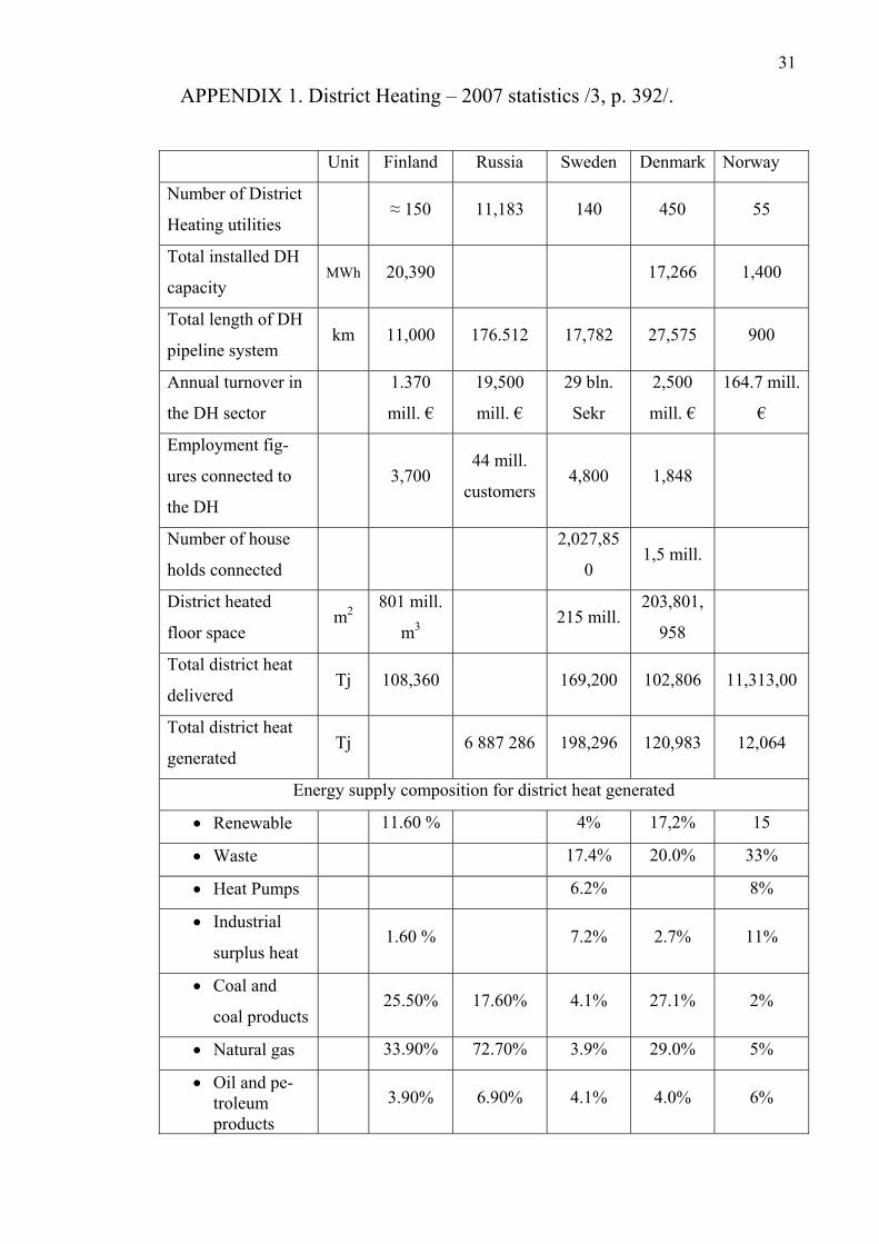
APPENDIX 1. District Heating – 2007 statistics
APPENDIX 2. Climatic map
APPENDIX 3. Climatic parameters of Irkutsk, Moscow, and Saransk
APPENDIX 4. The results of ALFA-LAVAL Company investigation
1
1 INTRODUCTION
District heating (DH) is a widely used form of heating in densely-built areas of North-
ern Europe, the United States of America, and most of Russia. That is why the supply
of heating energy must be reliable, safe, efficient, and have a very high degree of se-
curity of conveying. In order to meet all these requirements the system must be
properly designed and run.
At present time the total length of district heating network in Russia is quite large.
Most of networks need urgent rehabilitation according to modern standards. Upgrad-
ing district heating networks in densely-built areas would reduce total consumption of
heating energy.
In order to modernize Russian DH systems it is necessary to study and analyze at first
the situation with DH in Russia, and then the foreign experience in this field. Finland
is the country bordering Russia and having quite similar weather conditions with the
northern regions of Russia. And besides, Finnish DH system is considered to be ener-
gy efficient, safe, and customer oriented. That is why in this thesis work the structure
and principle of operation of Finnish DH systems are considered. The aim of this
work is to examine Finnish experience in the field of DH systems and to consider the
possibilities of applying Finnish methods in Russian conditions.
2 GENERAL
2.1 District heating market
District heating market in Northern Europe is growing rapidly every year, and now
accounts for more than half of all heating in different types of buildings. For example,
in Finland estimated number of residents heated by district heating is about 2.57 mil-
lion inhabitants, in Sweden - about 1.85 million households heated in residential
houses, 182710 in single family houses, and 91.0 million square meters in other prem-
ises, and in Denmark – 1.54 million households which is about 61% /1, pp. 113, 358,
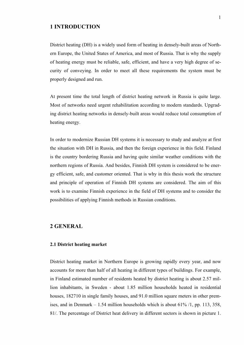
81/. The percentage of District heat delivery in different sectors is shown in picture 1.
2
In Russia district heating market is already developed. About 91% of all buildings in
large cities and about 60% in small towns are connected to district heating network /1,
p. 74/. More detailed information about the number of consumers, kinds of fuel used
for heat energy production in DH sector, and amounts of CO2 emission from district
heat production are given in Appendix 1.
Sweden Finland
Denmark
Picture 1. District heat delivery by sectors /1, pp. 359, 114, 81/.
2.2 District heating influence on the environment
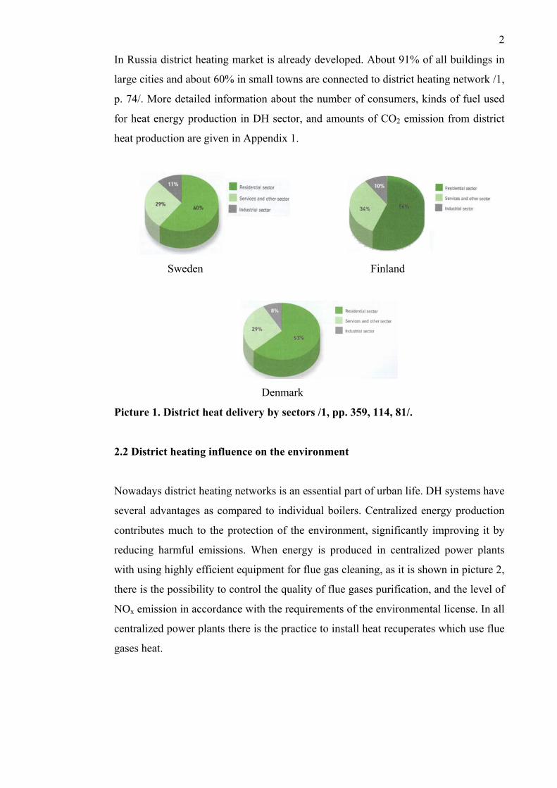
Nowadays district heating networks is an essential part of urban life. DH systems have
several advantages as compared to individual boilers. Centralized energy production
contributes much to the protection of the environment, significantly improving it by
reducing harmful emissions. When energy is produced in centralized power plants
with using highly efficient equipment for flue gas cleaning, as it is shown in picture 2,
there is the possibility to control the quality of flue gases purification, and the level of
NOx emission in accordance with the requirements of the environmental license. In all
centralized power plants there is the practice to install heat recuperates which use flue
gases heat.
3
Picture 2. Principle scheme of cleaning of flue gas /3, p. 14/.
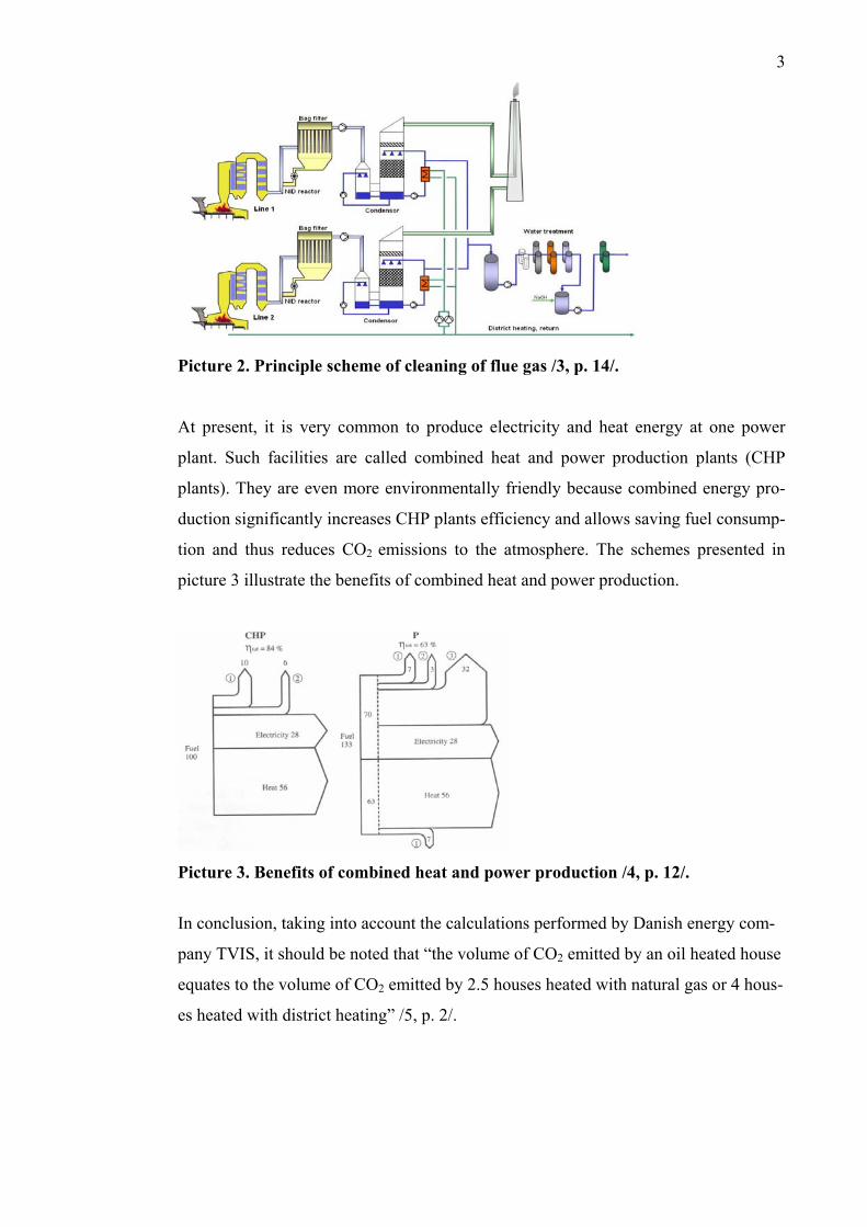
At present, it is very common to produce electricity and heat energy at one power
plant. Such facilities are called combined heat and power production plants (CHP
plants). They are even more environmentally friendly because combined energy pro-
duction significantly increases CHP plants efficiency and allows saving fuel consump-
tion and thus reduces CO2 emissions to the atmosphere. The schemes presented in
picture 3 illustrate the benefits of combined heat and power production.
Picture 3. Benefits of combined heat and power production /4, p. 12/.
In conclusion, taking into account the calculations performed by Danish energy com-
pany TVIS, it should be noted that “the volume of CO2 emitted by an oil heated house
equates to the volume of CO2 emitted by 2.5 houses heated with natural gas or 4 hous-
es heated with district heating” /5, p. 2/.
4
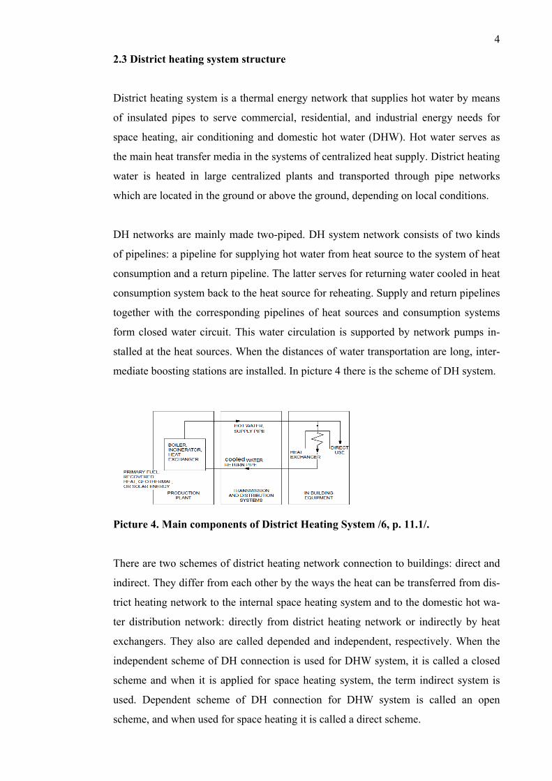
2.3 District heating system structure
District heating system is a thermal energy network that supplies hot water by means
of insulated pipes to serve commercial, residential, and industrial energy needs for
space heating, air conditioning and domestic hot water (DHW). Hot water serves as
the main heat transfer media in the systems of centralized heat supply. District heating
water is heated in large centralized plants and transported through pipe networks
which are located in the ground or above the ground, depending on local conditions.
DH networks are mainly made two-piped. DH system network consists of two kinds
of pipelines: a pipeline for supplying hot water from heat source to the system of heat
consumption and a return pipeline. The latter serves for returning water cooled in heat
consumption system back to the heat source for reheating. Supply and return pipelines
together with the corresponding pipelines of heat sources and consumption systems
form closed water circuit. This water circulation is supported by network pumps in-
stalled at the heat sources. When the distances of water transportation are long, inter-
mediate boosting stations are installed. In picture 4 there is the scheme of DH system.
Picture 4. Main components of District Heating System /6, p. 11.1/.
There are two schemes of district heating network connection to buildings: direct and
indirect. They differ from each other by the ways the heat can be transferred from dis-
trict heating network to the internal space heating system and to the domestic hot wa-
ter distribution network: directly from district heating network or indirectly by heat
exchangers. They also are called depended and independent, respectively. When the
independent scheme of DH connection is used for DHW system, it is called a closed
scheme and when it is applied for space heating system, the term indirect system is
used. Dependent scheme of DH connection for DHW system is called an open
scheme, and when used for space heating it is called a direct scheme.
5
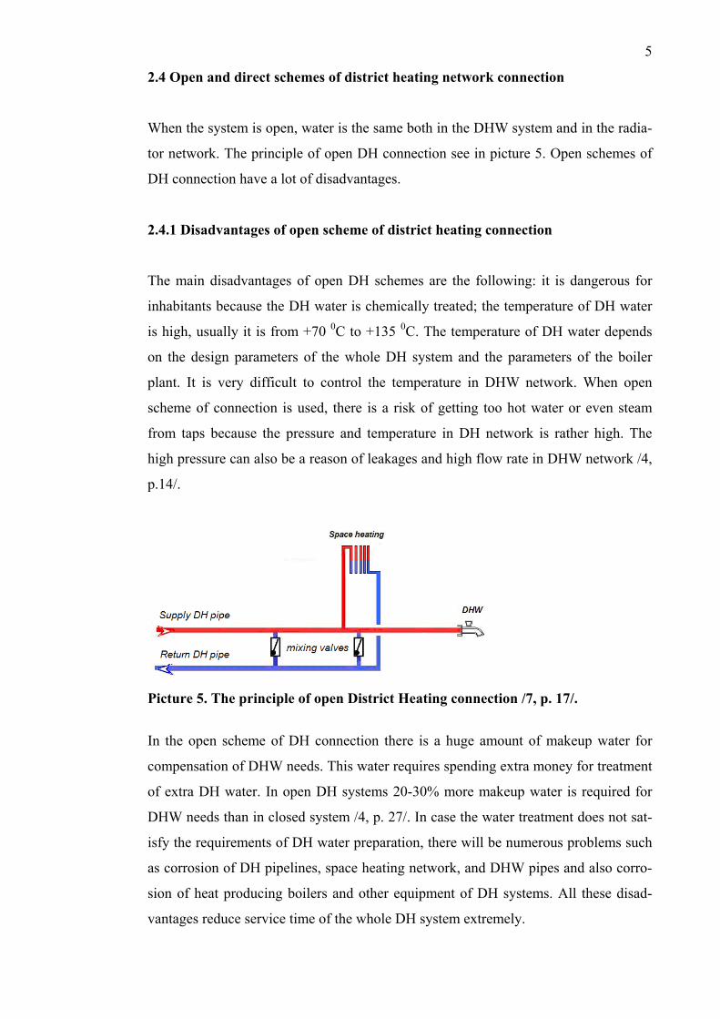
2.4 Open and direct schemes of district heating network connection
When the system is open, water is the same both in the DHW system and in the radia-
tor network. The principle of open DH connection see in picture 5. Open schemes of
DH connection have a lot of disadvantages.
2.4.1 Disadvantages of open scheme of district heating connection
The main disadvantages of open DH schemes are the following: it is dangerous for
inhabitants because the DH water is chemically treated; the temperature of DH water
is high, usually it is from +70 0C to +135 0C. The temperature of DH water depends
on the design parameters of the whole DH system and the parameters of the boiler
plant. It is very difficult to control the temperature in DHW network. When open
scheme of connection is used, there is a risk of getting too hot water or even steam
from taps because the pressure and temperature in DH network is rather high. The
high pressure can also be a reason of leakages and high flow rate in DHW network /4,
p.14/.
Picture 5. The principle of open District Heating connection /7, p. 17/.
In the open scheme of DH connection there is a huge amount of makeup water for
compensation of DHW needs. This water requires spending extra money for treatment
of extra DH water. In open DH systems 20-30% more makeup water is required for
DHW needs than in closed system /4, p. 27/. In case the water treatment does not sat-
isfy the requirements of DH water preparation, there will be numerous problems such
as corrosion of DH pipelines, space heating network, and DHW pipes and also corro-
sion of heat producing boilers and other equipment of DH systems. All these disad-
vantages reduce service time of the whole DH system extremely.
6
2.4.2 Advantages of open scheme of district heating connection
This scheme requires neither heat exchangers nor circulation pumps. Thus the ad-
vantage of the open scheme of DH connection is that it does not need a lot of money
investments for equipment preparing DHW. This scheme requires neither heat ex-
changers nor circulation pumps.
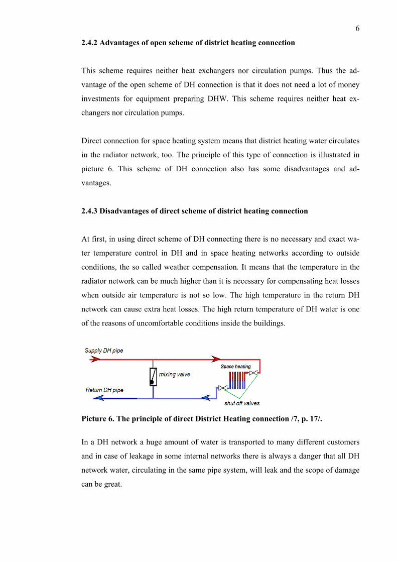
Direct connection for space heating system means that district heating water circulates
in the radiator network, too. The principle of this type of connection is illustrated in
picture 6. This scheme of DH connection also has some disadvantages and ad-
vantages.
2.4.3 Disadvantages of direct scheme of district heating connection
At first, in using direct scheme of DH connecting there is no necessary and exact wa-
ter temperature control in DH and in space heating networks according to outside
conditions, the so called weather compensation. It means that the temperature in the
radiator network can be much higher than it is necessary for compensating heat losses
when outside air temperature is not so low. The high temperature in the return DH
network can cause extra heat losses. The high return temperature of DH water is one
of the reasons of uncomfortable conditions inside the buildings.
Picture 6. The principle of direct District Heating connection /7, p. 17/.
In a DH network a huge amount of water is transported to many different customers
and in case of leakage in some internal networks there is always a danger that all DH
network water, circulating in the same pipe system, will leak and the scope of damage
can be great.

7
2.4.4 Advantages of direct scheme of district heating connection
The main advantage of direct DH connection is that it does not require large invest-
ments in automation system of every building because DH water parameters are regu-
lated for the groups of the buildings. The system with direct DH connection does not
require the installation of circulation pumps on the space heating side. When the
building is not tall, it is not necessary to install the pumps in the building because the
DH network pressure is enough to provide water circulation in the internal networks.
2.5 Closed and indirect schemes of district heating network connection
In the closed system DHW is produced, that is heated by heat exchangers. When indi-
rect connection is used for space heating systems, the DH and the radiator networks
are separated from each other by means of heat exchangers. The scheme of closed and
indirect DH connection is given in picture 7. In comparison with open and direct
schemes of connection to DH network, closed and indirect schemes have more ad-
vantages than disadvantages.
Picture 7. The principle of the closed and indirect District Heating connection /4,
p. 26/.
2.5.1 Advantages of closed and indirect schemes of district heating network con-
nection
First of all, it should be noted that closed and indirect scheme is the safest scheme of
connecting consumers to DH network. The main advantages of indirect connection are
8
the following: uniform heating of all the flats in the building; leakage in either the
district heating pipeline or the radiator network is only limited to that system and
doesn’t drain the other one; automatic control during the whole heating season takes
into account the weather compensation and the possibility of saving energy during the
transition season from 20 to 40% of total consumption and also energy saving due to
temperature reducing; DHW is heated in heat exchanges and that is why this system
needs minimal extra makeup water for replacement of DH water resulting in low oxy-
gen levels and significant reduction of corrosion of DH networks and other DH
equipment; safety factor for example, the pressure and the temperature are lower in
the building; this type of system makes each customer more independent as far as heat
energy is concerned because consumers can get their own control of all necessary pa-
rameters for creating individual thermal comfort, and have energy costs saving /4, pp.
26, 33/.
2.5.2 Disadvantages of closed and indirect schemes of district heating network
connection
There are two main disadvantages of closed and indirect schemes of DH connection.
This system requires more technological equipment, such as heat exchangers and
pumps and therefore it is more expensive. In case of high pressure it is necessary to
install expansion system at the secondary side for preventing destroys of internal net-
works.
3 DISTRICT HEATING SYSTEMS IN RUSSIA
3.1 The importance of district heating in Russia
Russia is a country with severe climate conditions. Cold season in the most of regions
lasts more than 200 days at average outdoor air temperature below -50C. In the north-
ern climatic zone, which covers almost half of Russia’s territory, heating period char-
acteristics are even more severe. For example, the heating period for town Chita is
238 days at average outdoor temperature -12.40C, and for Verkhojansk town it is 272
days at average outdoor air temperature -25.20C. Therefore, well designed, properly
9
operated, and having high standards of performance DH system is extremely im-
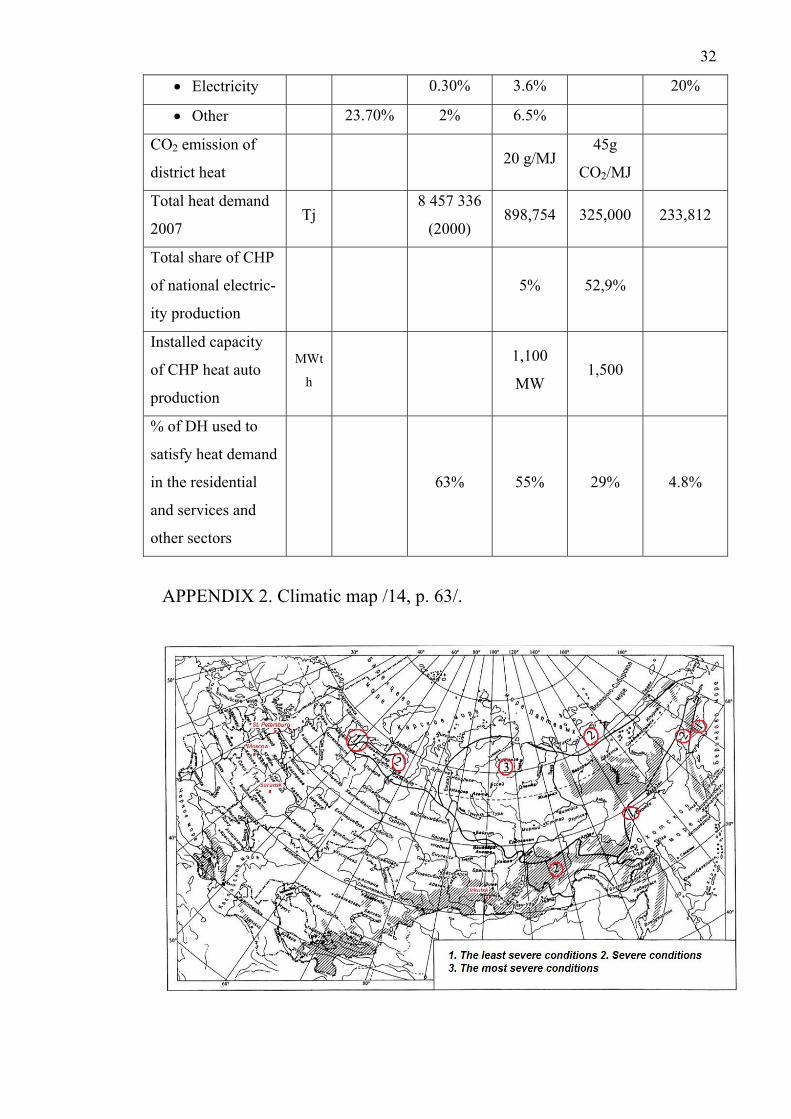
portant in Russian climatic conditions. Climatic map of Russia is shown in Appendix
2. About 90% of all dwelling buildings in densely-populated areas of Russia are con-
nected to district heating systems. The total length of DH network in Russia is about
275. 000 kilometers /8, p. 35/.
It is not a simple matter to maintain optimum comfortable indoor climate parameters
in such conditions. More than 30% of all the fuel extracted in the country, which
makes about 600 million tons of standard fuel, is to be burnt to provide buildings with
heat energy /9, p. 6/. For the most efficient use of fuel and in order to provide the con-
sumers with heat energy safely, it is advisable to use DH systems in densely-built re-
gions.
3.2 Present situation of district heating systems
Nowadays in Russian cities there are a lot of consumers not satisfied with centralized
DH system and who would prefer not to connect their buildings to district heating
network, but to use autonomous heating systems. The main reasons of that are the
following: the system does not meet the customer needs, the system is not energy effi-
cient, and using existing parameters makes the operation of such a system dangerous.
At present time power-generating sector in Russia is in a difficult situation. Equip-
ment, methods of production, transportation and regulation of heat energy have be-
come out of date. Steady growth of the volumes of energy consumption revealed the
problem of generating capacities deficit. At present in operation in Russia there are
485 CHP plants, about 6500 boiler-houses with the capacity more than 24 MW, more
than 100,000 small boiler-houses and about 600,000 autonomous individual heat gen-
erators. About 35% of heat energy from all DH system heat loads is produced at CHP
plants. Total heat energy production in Russia is 2400 million MW/365 days. 1265
million MW are produced for the needs of residential consumers, 1130 million MW
are produced for industrial enterprises. 400 millions tons of standard fuel are spent a
year to produce this energy amount /8, p. 32/. According to the data of Russian Feder-
ation Ministry of Energy the level of total DH systems wear is 59%. Heat generating
equipment wear is 68%, DH networks wear is 59%. It is estimate that at present time
15% of DH networks demand urgent replacement. In order to make the condition of
10
DH water transportation system reliable, it is necessary to completely repair or to
build anew 150,000 km of DH networks /8, p. 39/. According to the data presented by
the head of the Ministry of Energy Mr. Basargin in 2009 there were 1520 accidents at
the DH networks serving residential sector. The Minister also marked that during the
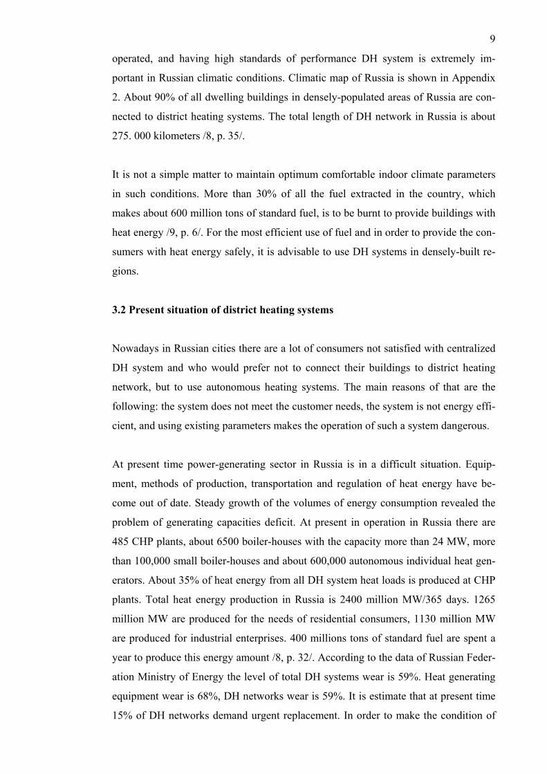
similar period in 2008 there were 1380 accidents. Thus, one can draw a conclusion
that DH systems are in the state of emergency. See picture 8.
Picture 8. Example of some district heating pipelines condition. /8, p. 35/.
3.3 Standards of Russian district heating system
Standards and specifications of the existing in Russia DH system were developed in
1950 s. They have not actually changed since that time. At the time of creation it was
a quite modern, economically efficient DH system which allowed rapid transition
from individual heat sources to centralized heat supply. The main purpose of these
standards was to build fast a system which should not be material-intensive. Also it
was not so important to take into account prices for oil, gas, coal, and other energy
sources, because there has not been a lack of fuel in Russia.
For example, the standards for optimization of combined heat and electrical energy
production these standards were accepted in 1970s and are still valid. According to
them it is permitted to build CHP plants with minimal heat capacity of 300-500 MW.
Construction of the same CHP plants in Western Europe is considered economically
profitable with heat capacity of 30-40 MW /4, p. 16/.
Some Russian standards of designing DH network are not energy efficient and even
can be dangerous for consumers. Until now according to Russian standards of design-
11
ing DH systems it is allowed to connect buildings using open scheme of connection to
DH network. It should be noted that dependent scheme of DH connection is recom-
mended by Russian norms of designing DH systems. As mentioned earlier they are
quite dangerous and not efficient types of DH connection.
According to Russian standards the temperature in DHW network should not be less
than +600C. So, when open and direct schemes of DH connection are used, during
transition season water in DH systems is supplied at the temperature about +600C.
This situation is very common to St. Petersburg. But according to calculations of heat
losses, taking into account weather compensation, it is not necessary to supply water
to radiator network with such a temperature. This is the reason of quite high tempera-
ture in radiator network and uncomfortable conditions inside buildings due to over-
heated internal spaces. Thus, water in a radiator network does not get cold enough and
returns to a boiler plant quite hot. The high temperature of return DH water is the re-
sult of bigger heat losses in return DH pipelines.
3.4 Principle district heating systems in Russia
Russian DH system scheme consists of the following main parts: source of heat, dis-
tribution network, central substation, and individual substation. The principle of oper-
ation of such a system is the following: heated water leaves the source of heat at the
temperature +1350C. Then it is delivered to the central substation. There it is cooled to
+950C, for some groups of buildings to +1150C. The reduction of water temperature is
performed by admixing cooled water from the return pipeline of the DH system.
When DH water temperature is changed, it is delivered to the individual substation.
Distribution of DH water to DHW system, to DH system, and to heat supply of air
handling units (AHU) occurs in the individual substation. The principle of operation
of individual substation see in chapter 3, paragraph 3.6.
It is characteristic for Russian DH systems to use only one source of heat energy pro-
duction for the entire DH system without providing additional boiler-houses for reser-
vation and compensation of the loads at the time of the largest heat energy consump-
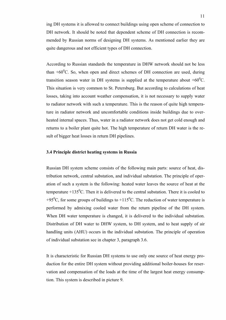
tion. This system is described in picture 9.
12
Picture 9. Russian District Heating system with one source of heat /4, p. 17/.
3.5 Central substation
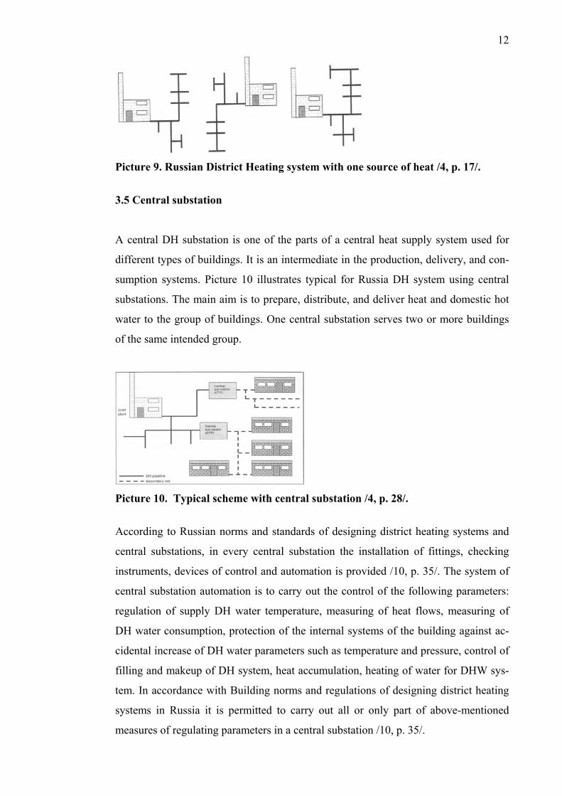
A central DH substation is one of the parts of a central heat supply system used for
different types of buildings. It is an intermediate in the production, delivery, and con-
sumption systems. Picture 10 illustrates typical for Russia DH system using central
substations. The main aim is to prepare, distribute, and deliver heat and domestic hot
water to the group of buildings. One central substation serves two or more buildings
of the same intended group.
Picture 10. Typical scheme with central substation /4, p. 28/.
According to Russian norms and standards of designing district heating systems and
central substations, in every central substation the installation of fittings, checking
instruments, devices of control and automation is provided /10, p. 35/. The system of
central substation automation is to carry out the control of the following parameters:
regulation of supply DH water temperature, measuring of heat flows, measuring of
DH water consumption, protection of the internal systems of the building against ac-
cidental increase of DH water parameters such as temperature and pressure, control of
filling and makeup of DH system, heat accumulation, heating of water for DHW sys-
tem. In accordance with Building norms and regulations of designing district heating
systems in Russia it is permitted to carry out all or only part of above-mentioned
measures of regulating parameters in a central substation /10, p. 35/.

13
Utilization of systems distributing heat energy by means of central substations is a
less efficient method as compared with applying individual substations installed in
every building. Systems with central substations have more heat energy losses at all
DH system levels after central substation resulting in heat losses by consumers due to
the overheating of the building during transition season /4, p. 29/.
Large heat energy losses arise because of the low quality of the automation system
which does not permit to control individual heat energy consumption in the building.
Due to the imperfection of the norms of designing DH systems it is also not possible
to control the parameters of the entire DH system more precisely. In practice, it is
quite often that the system of automation and control at the central substation is not
used. That is one of the reasons of very low cooling of return DH water in the cold
season. Design temperature of return DH water is +60 - +700C, but in real conditions
the temperature difference of return and supply DH water is only +20 - +300C. Thus,
the low temperature of return DH water is the result of the DH network low heat car-
rying capacity. Low heat carrying capacity of the DH network is the cause of addi-
tional expenses for extra pumping and extra heat losses in DH network. In comparison
with the corresponding indices in Finland, the expenditure of electric energy for extra
pumping of DH water in Russia is two times more. For example, in Russia electric
energy expenditure is about 20 - 25 kWh/MWh district heat from production. In Fin-
land this index is about 10 kWh/MWh /4, p. 30/.
It is also should be noted that in a central substation the control of DH water parame-
ters will never be carried out as exactly as it can be performed in an individual substa-
tion. Low quality control of DH water parameters after central substation is explained
by too long pipelines from the control point to the consumer, and also by the difficul-
ties of balancing the internal space heating system. The pipelines of quite great length
result in the increase of heat losses and in the reduction of return DH water tempera-
ture due to the necessity of overheating the supply DH water in order to provide
enough heat energy in every flat.
The main disadvantage of heat delivery group regulation at the central substation is
that every scheme is worked out for buildings with definite purpose, but regulation of
heat flows for groups of buildings with different thermal conditions is impossible by
using only one scheme. For example, when one scheme of heat flows regulation is
14
used for a group of consumers consisting of residential and administration buildings,
heat energy supply is inefficient during transitional heating season with the open
scheme of DH system connection. In order to provide the required by the norms water
temperature in DHW system, the temperature of water in DH network is maintained at
a higher level than it is necessary for a heating system with small heat losses of the
building. In this case, the main aim of the central substation automation system is to
prevent the overheating of the buildings. Thus, larger amount of heat energy is pro-
duced than it is required.
In winter season, when DH water temperature in the space heating system is to be
higher than the temperature of water for DHW system needs, there occurs under de-
livery of heat energy to the consumers for space heating. For example, DH water tem-
perature can be lower than it is required according to the heating schedule because of
the damage at the heat source, fuel shortage or outdoor temperature fall below the
design temperature for heating system. In this situation, the purpose of the central
substation automation system is to prevent misalignment of DH network. When the
DH water temperature in the distribution network falls, automation system in the cen-
tral substation responds and opens the valves regulating the DH water temperature. As
a result, the uniform heat supply is not performed. This misbalance is lower on the
head sections and higher on the end sections of the DH network /4, pp. 30-31/.
The internal space heating system is connected to the central substation by means of
correction mixing pumps in case of the dependent scheme of connection with a mix-
ing valve in an individual substation of each building. In case of the closed scheme of
connection it is connected by means of heat exchangers. Domestic hot water systems
are connected to the central substation by means of heat exchangers in case of the
closed schemes of connection and for the open scheme of connection a mixing valve
is used. When buildings are connected to the central substation by means of the closed
DH scheme, there is a four-pipe DH system installed between the central substation
and the building. Such a scheme includes supply and return DH pipes for DHW and
space heating systems. When this scheme is used, investments increase considerably.
There is a large increase in heat energy losses and also much more electricity is used
for transporting water for DHW needs. It should be noted, that the service life of the
pipelines delivering water for DHW system is significantly shorter, because delivered
water is not treated and contains large amount of oxygen /4, p. 27/. In the picture 12
15
different schemes for connecting DHW and space heating systems with using a central
substation are shown.
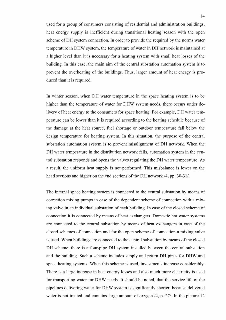
In the picture 11 the following marks are used: In the picture: РТГ – hot water tem-
perature regulator; РТО – heating system heat-carrying agent temperature regulator;
РП – heat-carrying agent consumption regulator; НС – mixing pump; ХВ – cold wa-
ter from city water pipe; ГВ – second grade heating hot water
Picture 11. Typical Russian solution with connection of space heating and DHW
to district heating network /4, p. 30/.
3.6 Individual substation
According to Russian standards and rules of designing DH systems, it is necessary to
install an individual substation in every building irrespective of the availability of the
central substation. In individual substation only those functions are provided which
are necessary for connecting the building to the DH network. Usually the following
equipment are installed in an individual substation: a mixing valve, filters for supply
and return DH pipes, accumulators of heat energy, thermal insulation, different fit-
tings, pumps when it is necessary to rise pressure in a supply pipeline of a space heat-
ing system, distribution and return manifolds as a rule, it is a pipeline of a larger di-
ameter with the connection of the space heating system to it. In the picture 12 a typi-
cal scheme of an individual substation with a mixing valve installed in a residential
building is shown.
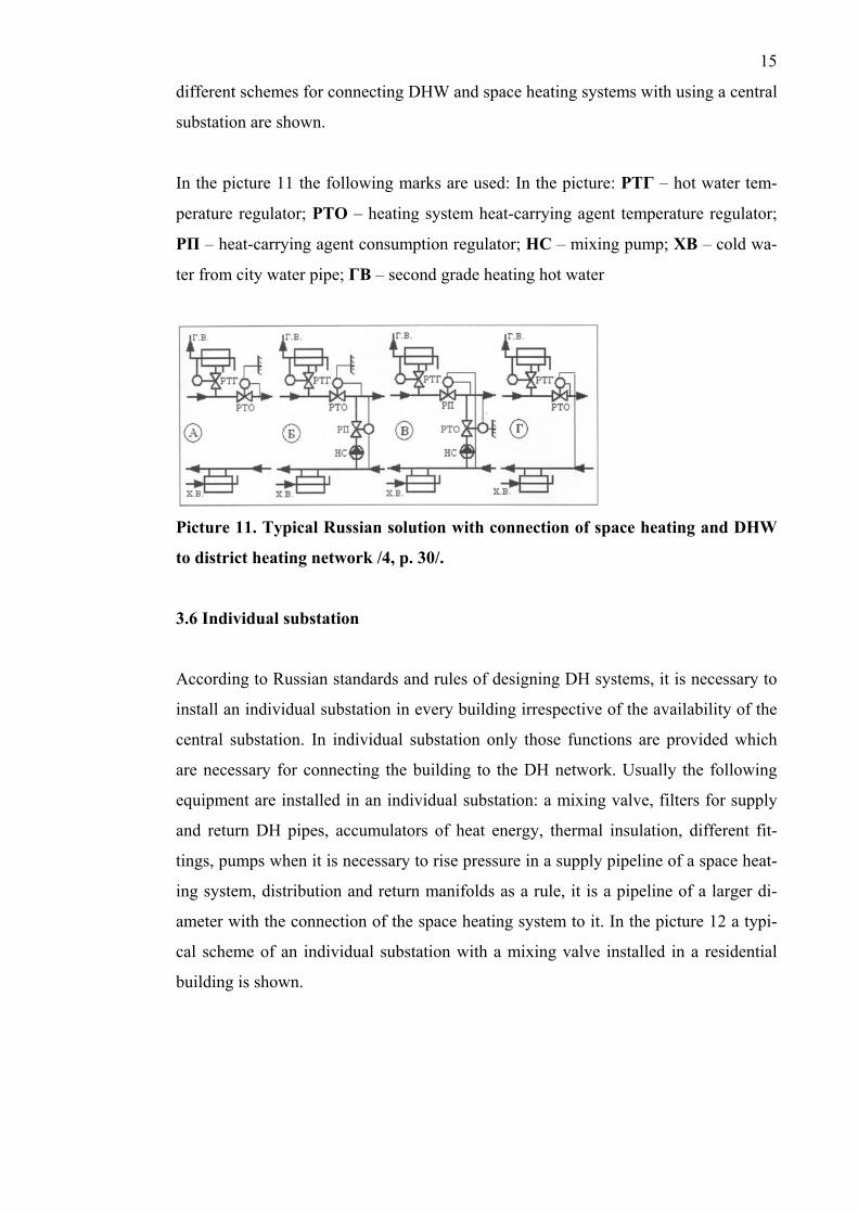
16
Picture 12. Scheme of individual substation /11/.
The main aim of the individual substation is distributing DH water for space heating
system and DHW. For regulating DH water temperature a mixing valve is usually
used. The principle of mixing valve operation see in chapter 3, paragraph 3.7. In ac-
cordance with the norms of designing individual substations, space heating systems,
ventilation and air conditioning should be connected to two-pipe DH system by de-
pendent scheme of DH connection. It is allowed to connect these systems to the DH
network by means of heat exchangers, with the usage of reserve heat exchangers. For
every system two heat exchangers are installed, on condition that each heat exchanger
is rated for 75% capacity from the total heating load /10, p. 7/. Connecting the internal
systems of the building by the independent scheme of DH connection makes the sys-
tem much more expensive, and that is why such connection scheme is found very sel-
dom.
3.7 Principle of mixing valve operation
A mixing valve is a widely used means for regulating the temperature of space heating
water in internal networks of buildings in Russia. It is used in DH systems with the
following parameters of water: maximum temperature is +1500C, maximum pressure
is 1.6 MPa. A mixing valve given in picture 13 is installed in individual substations in
every building. Its main purpose is to reduce the space heating water temperature in
radiator and DHW networks. During the transition season it reduces the temperature
of water in a radiator network, and in winter it reduces the temperature of water for
DHW needs according to the allowable range of temperatures for those systems.
17
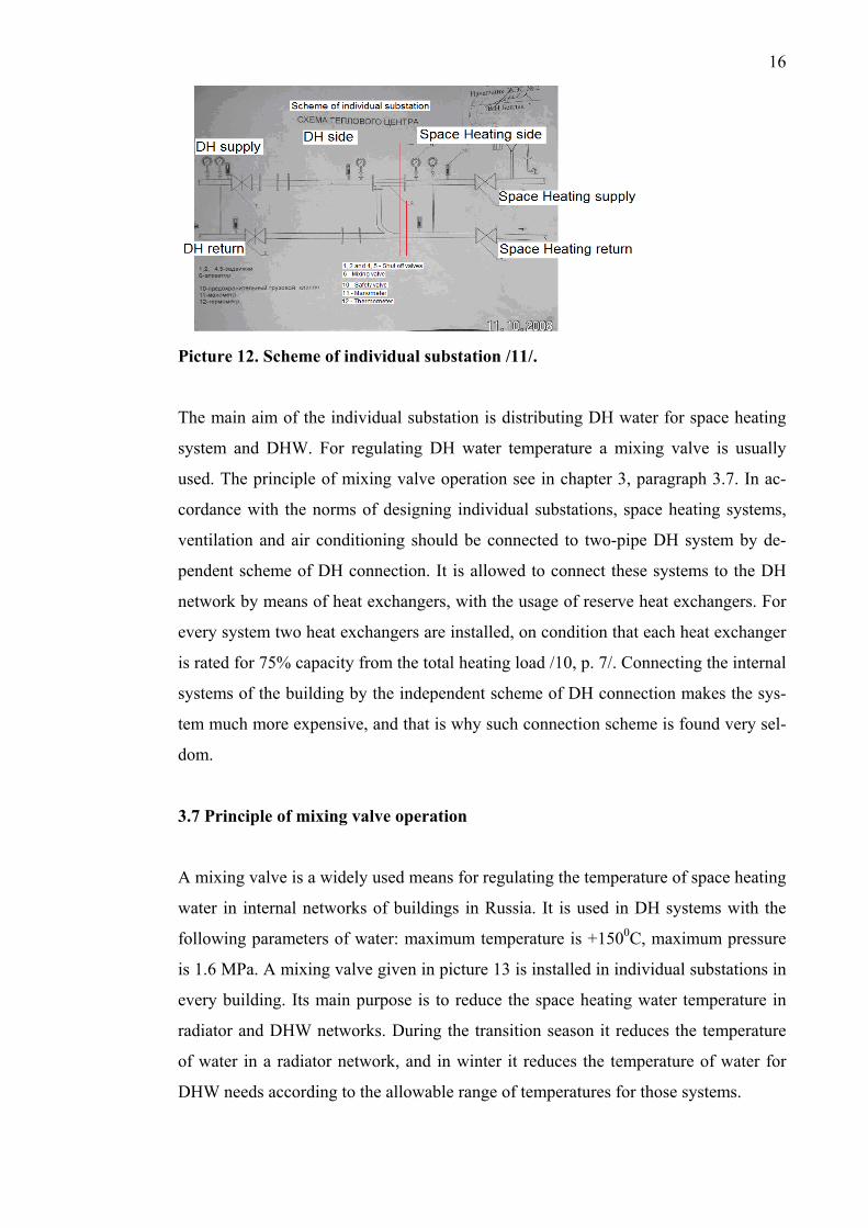
Picture 13. Mixing valve /11/.
The principle of mixing valve operation is based on mixing DH water from return
pipeline of a radiator network with supplied water. DH water from supply pipeline is
delivered to a conic removable nozzle where the water velocity sharply increases. As
a result, the water jet coming out of the nozzle to a mixing chamber draws cooled wa-
ter from a space heating return pipeline of a radiator network into the inner cavity of a
mixing valve. Thus, in a mixing valve occurs mixing and reducing the temperature of
the water supplied to the internal networks. Mixing valve operation depends much on
correct choice of sizes and diameters of water delivery pipes leading from supply
pipeline of DH system and return pipeline of internal space heating system and also
on nozzle diameter choice.
Mixing valves have gained wide acceptance in Russia because they don't require large
financial expenditures during their operational life; they don't need installing automat-
ic systems in contrast to systems using heat exchangers; they don't require constant
inspection by service personnel.
4. DISTRICT HEATING SYSTEMS IN FINLAND
4.1 The importance of district heating systems in Finland
Finland is located in the northern part of Europe. Climatic conditions there are such
that the weather can change quite fast especially in winter time. The average January
temperature for the period 1971 - 2004 was -40C in the southern part of Finland, and
about -140C in the northern one. Heating degree days in Finland are counted between
3,900 and 6,400 /1, p. 112/. Thus, heat supply system in Finland should be reliable
and energy efficient. The most common form of heating buildings is DH system. It
18
has been in operation in that country from the early 1950s /12/. More than half of
Finnish inhabitants live in the houses heated by DH system.
4.2 District heating system development
Finnish DH system was formed under the influence of market conditions in the eco-
nomics. Great influence on DH system was exerted by the energy saving policy sup-
ported by the government. In the course of the development common approaches in
the solution of technological problems of heat supplying were worked out. The efforts
were aimed at creating reliable and high quality heat supply to the consumers at a rea-
sonable price /4, p. 10/.
The main advantages of the developed in Finland DH system have become the follow-
ing factors: the possibility of combined heat and electricity production, safety and
beneficial for the environment approach in creation of highly integrated power sys-
tem. DH system gives practically complete versatility as far as kinds of fuel are con-
cerned. They can include fossil, renewable, and bio fuels. The usage of waste heat
from different sources is also possible /4, pp. 11/.
4.3 Present state of Finnish district heating system
At present time in Finland closed system of heat supply with the independent connec-
tion of consumers is used. The advantage of this type of connection is that DH net-
work and space heating network are two independent from each other systems. This
means that in case of an accident on DH network and resulting stoppage of DH water
delivery to the individual substation the water in the heating system will continue its
circulation. Water circulation will allow to maintain normal thermal conditions during
some period of time.
Finland is the world’s leader in the field of Combined Heat and Power (CHP) produc-
tion. Of the total heat energy production amount 75% heat are produced by means of
co-generation of heat and electric energy /12/. Production of heat energy at CHP
plants is very efficient and allows fuel savings the amount of which is given in picture
14. And only 25% of the heat is produced in the Heat only Boilers (HOB).
19
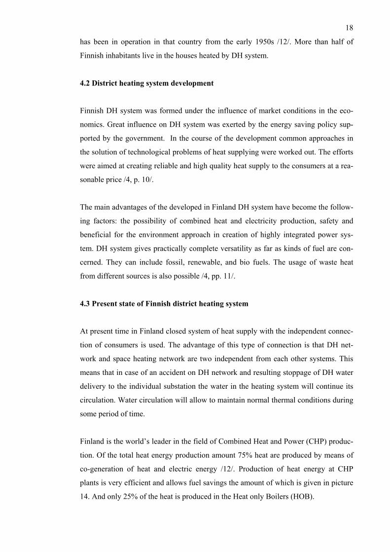
Picture 14. Savings in fuel consumption due to CHP /12/.
Finnish CHPs work with almost constant load all the year round. A small number of
peak demands during the coldest days in winter time are compensated with the help of
several peak boilers situated in different DH network parts /4, p. 15/. The scheme of
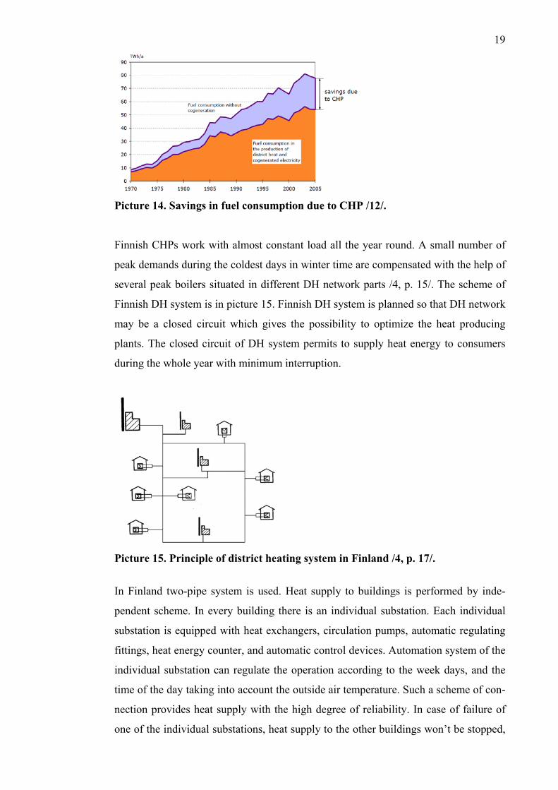
Finnish DH system is in picture 15. Finnish DH system is planned so that DH network
may be a closed circuit which gives the possibility to optimize the heat producing
plants. The closed circuit of DH system permits to supply heat energy to consumers
during the whole year with minimum interruption.
Picture 15. Principle of district heating system in Finland /4, p. 17/.
In Finland two-pipe system is used. Heat supply to buildings is performed by inde-
pendent scheme. In every building there is an individual substation. Each individual
substation is equipped with heat exchangers, circulation pumps, automatic regulating
fittings, heat energy counter, and automatic control devices. Automation system of the
individual substation can regulate the operation according to the week days, and the
time of the day taking into account the outside air temperature. Such a scheme of con-
nection provides heat supply with the high degree of reliability. In case of failure of
one of the individual substations, heat supply to the other buildings won’t be stopped,
20
as it happens in case with central substation. Internal space heating system is equipped
with a thermostat valve at every heating device, which makes the system more cus-
tomer-oriented and allows to save energy.
It should be noted that the heating system can start working at any time of the year as
soon as it gets information about quite low temperature of the outside air. Centralized
heat supply is built on the base of either modern boiler-houses, or CHP plants. In Fin-
land it is considered that combined heat and energy production is economically profit-
able starting at 10 MW of electric power that is 35 - 45 MW of heat power.
An important factor for the efficient DH system operation is the level of the tempera-
ture in supply DH pipeline. Previously, Finnish DH system was planned with the tem-
perature of water at +1200C in supply pipeline of the DH network. At present the de-
sign temperature is +1150C. One can suppose that the parameters of the temperature in
DH network will be some more lowered with the aim to increase energy efficiency.
Consequently, in order to compensate the demand in heat energy it is necessary to
increase the amount of the delivered DH water. The lowering of DH water tempera-
ture will result in the increase of electric energy output at CHP plant. When DH water
temperature is lowered, the pressure in DH network will become lower, too. As a re-
sult, reduced physical impact on the pipes will increase the service life of the pipe-
lines.
Nowadays in Finland in wide usage there are prefabricated individual substations
which are the functionally complete assemblies entirely manufactured at plants. They
fulfill the following main functions: heat cold water for DHW system; provide water
circulation in space heating and DHW systems; automatically regulate DH water con-
sumption and distribution of heat inside the buildings; control parameters of DH wa-
ter, water in DHW and space heating networks (pressure, temperature); protect inter-
nal networks against the accidental change of parameters; fill and makeup the internal
networks.

21
5. DISTRICT HEATING SYSTEM RENOVATION PROBLEM IN
RUSSIA
5.1 Danfoss company investigations
There were some attempts undertaken by foreign companies to change the existing in
Russia situation by introducing modern and efficient standards of designing and oper-
ation of DH system. Unfortunately, those attempts were too rare and too few and did
not have any considerable consequences.
With the purpose to renovate Russian DH systems by using modern equipment and
European standards of regulating heat flows, Danfoss Company has carried out the
investigations in two Russian cities, Moscow and Saransk /9/. The aim of the investi-
gation was to compare the amount of heat energy consumption in a building equipped
with an individual substation with a mixing valve, and in a building equipped with a
modern prefabricated individual substation with heat exchangers, electronic weather
compensator with precise automation system, automatic balancing valve, regulating
valves and so on, and circulation pumps.
The existing space heating system was fitted with thermostat valves and individual
heat energy counters. In DHW system, constant water circulation was provided. One
more aim of the investigation was to get and maintain comfortable temperature inside
the buildings, allowing the inhabitants themselves to set the desired temperature in
every room and to pay only for really consumed heat energy.
To perform the investigation two residential buildings of typical development of late
1990s were chosen. In Moscow a seven-storey residential building with 83 flats was
to be renovated. The building was connected to centralized heat supply system by
independent scheme with the usage of four-pipe DH system. The space heating system
was a vertical one-pipe system with radiators. Water for DHW was heated in heat ex-
changers installed in central substation. In Saransk a ten-storey residential building
with 80 flats was chosen for the experiment. The building was connected to DH sys-
tem by dependent scheme with two-pipe system.
22
Before the renovation, space heating and DHW systems were connected by individual
substation equipped with a mixing valve. After the renovation, a prefabricated indi-
vidual substation with heat exchangers for DHW system and with an automatic mix-
ing valve for space heating system was installed.
It should be noted that with individual substation with a mixing valve the inhabitants
of the buildings had to regulate internal thermal conditions of their flats by opening
the windows, making draughts, covering heating devices with dense materials which
may cause a fire. Thus, in some flats there was the overheating, while in the other flats
there was the under-supply of heat energy. Payments for heating were made according
to the norms calculated for 1 m2 of total flat area.
5.2 The results of Danfoss Company experiment
After the installation of energy saving equipment in the buildings under the experi-
ment, the control was carried out during one year and the following results were
achieved /9, p. 6/.
1. The inside air temperature rose from 10 – 160C to 20 – 220C
2. DHW temperature got back to normal and was 60 0C according to designed
conditions, resulting in water consumption reduction from 149 liters per per-
son to 128 liters per person a day.
3. Average saving of heat during the winter time was 27 % and during the transi-
tion season 45 – 55 %.
4. Consumption of circulating water reduced by 28 %.
5. Economy of electric power used for DH water pumping was 15 %.
6. Volume flow of additional water (makeup water) in a boiler reduced by 39 %.
7. Maximum temperature of DH water rose from 1040C to 1150C.
8. The temperature of return DH water reduced by 6 – 80C.
9. Hydraulic conditions of DH system were improved.
The prefabricated individual substation installed by Danfoss Company allows provid-
ing reliable and uniform heat supply to all rooms of the building. Owing to the auto-
matic system of weather compensation, the hot water temperature in the space heating
system changes depending on outside air temperature. A metering unit provides the
23
registration of the consumed energy amount. An individual heat energy counter moti-
vates the consumer to save energy. Calculations of heat energy payments showed that
the average cost of heating services in case of applying modern equipment had re-
duced by 30 - 40%, in comparison with the cost in buildings using individual substa-
tion with a mixing valve /9, p. 6/. The similar experiment was carried out in Russian
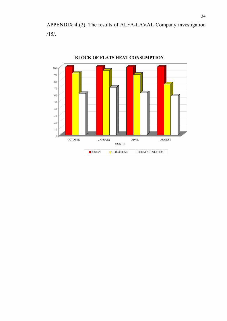
town Irkutsk by Alfa-Laval Company. The results of that experiment are given in Ap-
pendix 3. Irkutsk is situated in more severe climatic zone of building than Moscow
and Saransk. Therefore, the complexity of the task and the responsibility for making
comfortable thermal conditions inside the building were even grater. Climatic parame-
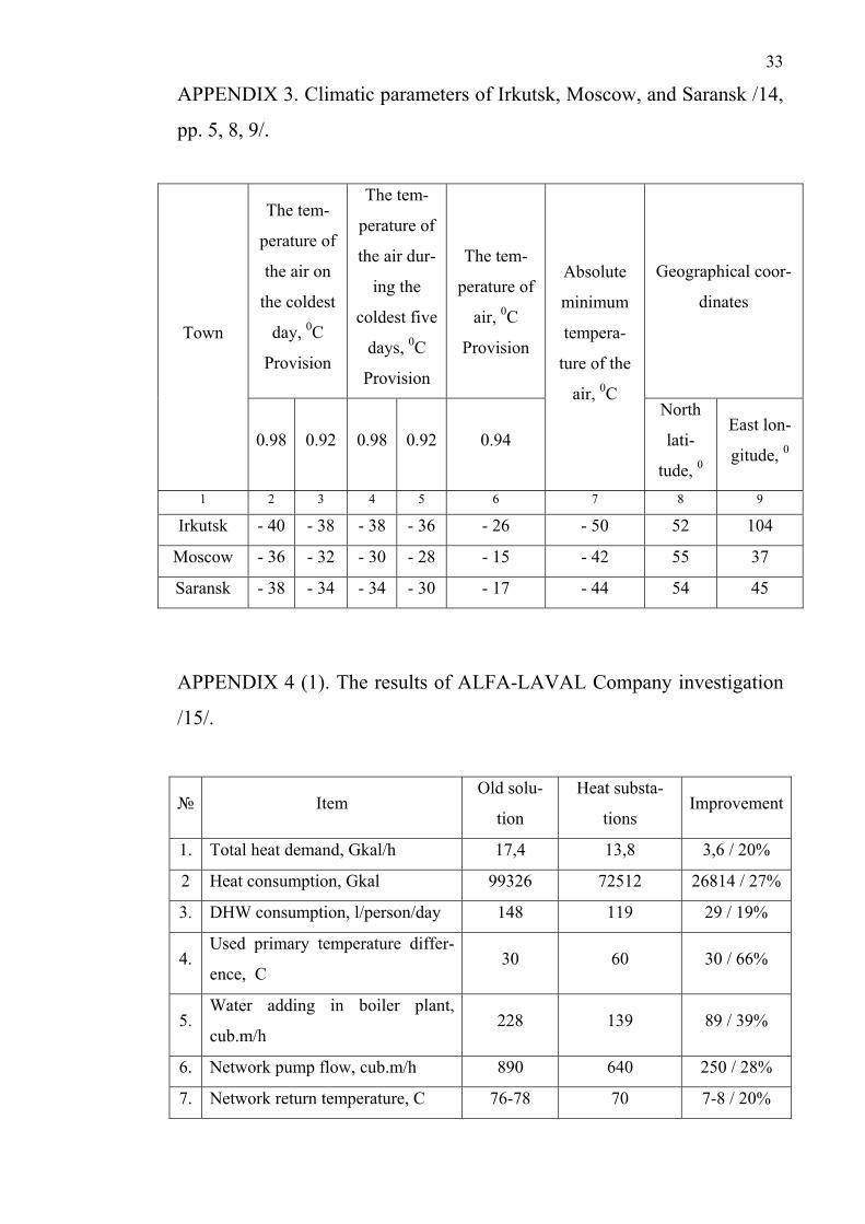
ters of the towns where the investigations were performed are given in Appendix 4.
5.3 Comparative analysis of two different schemes of district heating connection
While working at this bachelor thesis I investigated two multistory blocks of flats, one
being 9-storied and the other being 24-storied buildings. These residential buildings
were built in different periods, thus different techniques of designing DH and internal
space heating systems were applied. Both buildings are situated in St. Petersburg. The
purpose of the investigation was to control the change of thermal conditions and
DHW temperature in heating and non-heating periods.
The first task of the investigation was measuring of thermal conditions in residential
rooms. The investigation was performed in the cold season at the outside air tempera-
ture -150C and lower and in transition period at the outside air temperature from 00C
to +80C, both in cloudy weather conditions. The second task was to measure DHW
temperature at day-time and at night-time. Thermal conditions and DHW temperature
were measured during the half of the year. Each parameter was measured not less than
7 times on different days. Thermal condition measurements were performed on the
ground, the fourth and the top floors in the 9-storied building, and on the first, the
twelfth and the top floors in the 24-storied buildings.
5.3.1 Direct and open scheme
The first investigated building, building N 1, is a 9-storied block of flats built in St.
Petersburg in 1973. The building is connected by two-pipe DH system. The heating
system of this building is connected by dependent scheme of DH connection with us-
ing non-automatic mixing valve. Space heating system is one-pipe. Radiators are not
24
fitted with shut off valves. Thermostat valves are also not installed. DHW is connect-
ed by open scheme of DH connection. The DHW system is without a circulation pipe-
line.
In cold season thermal conditions of building N 1 didn’t meet the parameters of in-
door climate for residential buildings. Indoor air temperature was in the range from
+160C to +180C. In transition season thermal conditions didn’t meet the indoor cli-
mate parameters and energy efficiency requirements, either. Indoor air temperature
was in the range of +240C to +270C. The results of the investigation showed that the
DHW parameters didn’t meet the requirements of safety and energy efficiency. At
day-time during the heating season DHW temperature range was between +65 to
+780C, at night-time it was from +200C to +250C. In non-heating period DHW tem-
perature at day-time was +55 to +600C, which satisfied the requirements of safety. At
night-time DHW temperature was +25 to +300C.
5.3.2 Indirect and closed scheme
The second investigated building (building N 2) is a 24-storied block of flats built in
2007. The building is connected by two-pipe DH system. Heating system is connected
by independent DH connection scheme with using high speed heat exchangers, also
called plate heat exchangers. Heating system is radial, with the usage of distribution
and return manifolds. Every radiator is independently connected to the manifold. Eve-
ry radiator is fitted with a shut off valve. DHW system is connected by closed DH
connection scheme. DHW scheme is with the circulation pipeline.
Thermal conditions in building N 2 didn’t meet the requirements of indoor climate
parameters and the requirements of energy efficiency. Indoor air temperature in the
cold season was +24 to +270C. In transition season air temperature was +26 to +280C.
Under the influence of solar radiation it increased to +300C and even more. Parame-
ters of DHW at day and at night during the heating period were +59 to +610C. During
non-heating period of the year DHW temperature was approximately the same at day
and night time and was +57 to +590C.
After considering the achieved results it was found that thermal conditions didn’t sat-
isfy specified requirements. Individual substation of this building was investigated in
25
order to understand the reasons. Regulation of DH water coming into the heat ex-
changers of this individual substation was performed by hand. If it was necessary,
service staff changed the position of the shut off valve depending on the outside air
temperature. Such regulation does not provide the exact control of water temperature
on the space heating side in accordance with the outside conditions that is weather
compensation. The inhabitants of the building also could not control internal air tem-
perature by means of the installed on radiators shut off valves as precisely as it would
be possible to do by means of thermostat valves. It should be noted that automation
system and modern regulating equipment were provided by the design, but in the
course of the operation they were not used. It was because of the lack of highly skilled
service staff necessary for maintaining such equipment.
6. CONCLUSIONS
Having considered the current situation with DH systems in Russia and the successes
achieved in the field of heat supply in Finland, one may draw a conclusion that Rus-
sian DH networks need urgent renovation, taking into account and using Finnish ex-
perience of operating DH systems. It is quite expensive to solve the problem of in-
creasing energy efficiency of DH system and making it more customer oriented by
means of transition from centralized heat supply to individual sources of heat energy
production. Such transition to individual boilers requires more investments than DH
system renovation does /2. p. 75/.
However, the problem of renovation is also very complex and can’t be solved in one
stage and in a short period of time. Therefore, planning a program of renovation one
should clearly determine two parts of it: the long-term program and the tasks which
can and have to be done now.
6.1 Long-term program of District heating system renovation
The main requirements for the renovation of Russian DH system are the moderniza-
tion of heat energy sources, the introduction of combined heat and electric energy
26
production according to European standards of optimization, and the improvement of
means of conveyance and distribution of heat energy.
Later on it is necessary to continue the renovation of DH system and to pass from the
central substation system to a system with individual substations. By installing com-
pletely automatic individual substation in every building it is possible to pass from
four-pipe to two-pipe DH system which has a lot of advantages such as the following:
the total length of DH pipes is shortened, which results in cutting down the expendi-
ture of materials by 30 to 50%; investments for DH network maintenance are also cut
down; expenditures for building and insulating materials are much smaller; heat losses
in DH network are reduced by 20 to 30 %; consumption of electric energy used for
conveyance of heat-carrying agent is reduced; owing to automatic regulation of heat
supply to every particular consumer (a building) up to 15% heat used for heating pur-
poses is saved; the time of construction is reduced /4, pp. 32-33/.
6.2 The tasks of current renovation of District heating system
In Russian conditions it is rather difficult to immediately change the entire system of
conveyance and distribution of heat energy. Therefore, it is necessary to modernize
central substations according to the recommendations of Finnish specialists. In every
central substation it is necessary to install the following equipment: heat exchangers
for DHW and space heating systems, automation system controlling the parameters of
primary and secondary sides of the system, regulating valves, temperature sensors,
and circulation pumps; and thus, to pass to an independent DH system. The control of
space heating side should be performed taking into account the real heat energy needs
and using modern automation systems.
For increasing energy efficiency of DH system it is necessary to aim at lowering heat
load on DH system owing to: thermal insulation of the building, application of the
method of programmed regulation of heat energy consumption, and usage of efficient
thermal insulation of the pipelines. It is also necessary to work out recommendations
for maintaining DH system pipelines in a satisfactory state (that is to organize modern
repair work and anti-corrosion protection), to work out complex methods of designing
the system of DH systems automatization. This automation system will allow to bring
together the methods of heat balance of the building, calculation of the optimal load
27
on the heating system depending on the purpose of the building and the kind of heat-
ing system, calculation of the load on the ventilation system and DHW system for
residential, public, and industrial buildings. It should be noted that DH system has to
work with minimum interruption in heat supply all the year round.
When DH systems, at present working by open scheme of heat supply, are to be reno-
vated, in practice it is impossible to exactly copy Finnish DH system in conditions
existing in Russia. The reasons of this are the following: expensiveness of the system,
the huge scale of the renovated equipment, pipelines and subsidiary systems. When
changing from two-pipe DH system with dependent connection of the internal systems
to independent DH connection, it is necessary to enlarge the diameters of the pipelines
of cold water supply systems. This should be made in order to provide enough water
for DHW systems. This water is heated in heat exchangers in every building. At the
water supply stations it is also necessary to increase the capacity of the installations
for treatment drinking water used for the needs of DHW. Additional electrical energy
is necessary for the circulation pumps operation. In order to pass to independent DH
connection it is necessary to perform hydraulic calculation of all DH network pipe-
lines. If carrying capacity of the pipeline is not enough, it should be changed for a
pipeline of a large diameter.
Having taken into account all the above mentioned factors, one can conclude that such
DH system renovation for the existing buildings in current economic conditions is
very difficult. However, building norms and regulations should be revised taking into
consideration Finnish experience in operating two-pipe DH networks with independ-
ent connection to the buildings. These changes will give the possibility to use Finnish
DH system meeting all modern requirements in newly built districts. There are several
attempts to use Finnish experience in Russia already. One of the examples is the 24-
storied building which was considered in paragraph 5.3.2. However, the imperfection
of the existing building norms and regulations does not allow to achieve rational ener-
gy efficiency and comfortable thermal conditions.
Thus, for renovation of Russian DH systems new norms of designing and maintaining
should be worked out. It is necessary to detail very precisely how accurately the pa-
rameters in space heating and DHW systems will be maintained. Various influences
on changing these parameters should be taken into account. For example, when de-

28
signing DHW system it is necessary to determine the exact temperature differences in
the supply and circulation pipelines, as it is accepted in Finland.
For designing individual substations it is necessary to introduce in Russian norms
minimum quantity of automation systems which are obligatory for installation, and
also to give the accuracy of maintaining parameters. It is also necessary to install
thermostat valves on every heating device. Two-pipe scheme of heat supply should
be used for DH system. Central substation should be transformed to the building level
substations with heat exchangers for every system.
29
BIBLIOGRAPHY
1. Report of Euro Heat and Power May 2009. District heating and District cool-
ing. Belgium.
2. Biryuzova E.A. Comparative analysis of native and foreign heating systems.
In: Actual problems of modern construction. Part III (63 International scien-
tific-technical conference of young scientists). St.Petersburg, 2010. pp. 73-
75. [Бирюзова Е.А. Сравнительный анализ отечественной и зарубежной
системы теплоснабжения. Актуальные проблемы современного
строительства. Часть 3. (63-я Международная научно-техническая
конференция молодых учёных) Санкт-Петербург, 2010. стр. 73-75.]
3. HOT/COOL. International magazine on District heating and cooling. DBDH.
N1, 2009.
4. Veli-Matti, Makela, 2008. Bases for the recommendations for new norms in
Russian district heating. Mikkeli University of Applied Sciences.
5. Annual Report of TVIS Company. 2010
6. Electronic ASHARE book. District Heating part. 2007
7. Siemens Building technologies. District Heating Training Course. Chapter 4.
Mikkeli Polytechnic, 2002.
8. Biryuzova E.A. Analysis of methods of increasing energy efficiency of DH
system. In: Collected research reports. Issue 4.SPbUACE. St.Petersburg,
2009. pp.30-40. [Бирюзова Е.А. Анализ методов повышения
энергоэффективности системы теплоснабжения. Сборник докладов
СПбГАСУ. Выпуск 4. Санкт-Петербург 2009, стр. 30-40.]
9. Danfoss. Company website. Article “Energy efficient house” PDF – docu-
ment: Available in www.heating.danfoss.com: URL:
http://ru.heating.danfoss.com/Content/36022417-d750-4008-8232-
a8ea827d0e3a_MNU1 7433190_SIT130.html [referred 17.11.2009]
10. Building norms and regulations. Designing of DH. Moscow, 1986. [СНиП
2.04.07-86, Москва 1986]
11. Website of the Company selling mixing valve. Available in
12. www. kiparmotest.ru URL: http://kiparmotest.ru/catalog/elev_uz.html
[referre12.11.2010]

30
13. Website of Finnish Energy Industries. Available in http://www.energia.fi/EN
[referred 10.11.2010]
14. Building norms and regulations. Building Climatology, Moscow 2000.
[СНиП 23-01-99, Москва 2000]
15. Alfa-Laval Company home page.
31
APPENDIX 1. District Heating – 2007 statistics /3, p. 392/.
Unit Finland Russia Sweden Denmark Norway
Number of District
Heating utilities ≈ 150 11,183 140 450 55
Total installed DH
capacity MWh 20,390 17,266 1,400
Total length of DH
pipeline system km 11,000 176.512 17,782 27,575 900
Annual turnover in
the DH sector
1.370
mill. €
19,500
mill. €
29 bln.
Sekr
2,500
mill. €
164.7 mill.
€
Employment fig-
ures connected to
the DH
3,700 44 mill.
customers 4,800 1,848
Number of house
holds connected
2,027,85
0 1,5 mill.
District heated
floor space m2
801 mill.
m3 215 mill.
203,801,
958
Total district heat
delivered Tj 108,360 169,200 102,806 11,313,00
Total district heat
generated Tj 6 887 286 198,296 120,983 12,064
Energy supply composition for district heat generated
Renewable 11.60 % 4% 17,2% 15
Waste 17.4% 20.0% 33%
Heat Pumps 6.2% 8%
Industrial
surplus heat 1.60 % 7.2% 2.7% 11%
Coal and
coal products 25.50% 17.60% 4.1% 27.1% 2%
Natural gas 33.90% 72.70% 3.9% 29.0% 5%
Oil and pe-troleum products
3.90% 6.90% 4.1% 4.0% 6%
32
Electricity 0.30% 3.6% 20%
Other 23.70% 2% 6.5%
CO2 emission of
district heat 20 g/MJ
45g
CO2/MJ
Total heat demand
2007 Tj
8 457 336
(2000) 898,754 325,000 233,812
Total share of CHP
of national electric-
ity production
5% 52,9%
Installed capacity
of CHP heat auto
production
MWt
h
1,100
MW 1,500
% of DH used to
satisfy heat demand
in the residential
and services and
other sectors
63% 55% 29% 4.8%
APPENDIX 2. Climatic map /14, p. 63/.
33
APPENDIX 3. Climatic parameters of Irkutsk, Moscow, and Saransk /14,
pp. 5, 8, 9/.
Town
The tem-
perature of
the air on
the coldest
day, 0C
Provision
The tem-
perature of
the air dur-
ing the
coldest five
days, 0C
Provision
The tem-
perature of
air, 0C
Provision
Absolute
minimum
tempera-
ture of the
air, 0C
Geographical coor-
dinates
0.98 0.92 0.98 0.92 0.94
North
lati-
tude, 0
East lon-
gitude, 0
1 2 3 4 5 6 7 8 9
Irkutsk - 40 - 38 - 38 - 36 - 26 - 50 52 104
Moscow - 36 - 32 - 30 - 28 - 15 - 42 55 37
Saransk - 38 - 34 - 34 - 30 - 17 - 44 54 45
APPENDIX 4 (1). The results of ALFA-LAVAL Company investigation
/15/.
№ Item Old solu-
tion
Heat substa-
tions Improvement
1. Total heat demand, Gkal/h 17,4 13,8 3,6 / 20%
2 Heat consumption, Gkal 99326 72512 26814 / 27%
3. DHW consumption, l/person/day 148 119 29 / 19%
4. Used primary temperature differ-
ence, С 30 60 30 / 66%
5. Water adding in boiler plant,
cub.m/h 228 139 89 / 39%
6. Network pump flow, cub.m/h 890 640 250 / 28%
7. Network return temperature, C 76-78 70 7-8 / 20%
34
APPENDIX 4 (2). The results of ALFA-LAVAL Company investigation
/15/.
0
10
20
30
40
50
60
70
80
90
100
OCTOBER JANUARY APRIL AUGUST
MONTH
BLOCK OF FLATS HEAT CONSUMPTION
DESIGN OLD SCHEME HEAT SUBSTATION