Embed Size (px)
Citation preview
IEEE TRANSACTIONS ON VEHICULAR TECHNOLOGY, VOL. 58, NO. 1, JANUARY 2009 207
Distributive High-Rate Space–Frequency CodesAchieving Full Cooperative and Multipath Diversities
for Asynchronous Cooperative CommunicationsYabo Li, Wei Zhang, Member, IEEE, and Xiang-Gen Xia, Senior Member, IEEE
Abstract—In user-cooperative communications, relay nodes areusually asynchronous. By realizing that the processing in thefrequency domain is insensitive to the errors in the time domain,Mei et al. and Shin et al. recently applied the space–time-codedorthogonal frequency-division multiplexing (OFDM) techniqueto achieve full cooperative diversity for asynchronous coopera-tive communications, where orthogonal space–time block codes(particularly the Alamouti code) were used for relay nodes. In thispaper, we consider asynchronous cooperative communications,and the channels from one node to another node are frequency-selective fading. We propose a high-rate space–frequency codingmethod and prove that it can achieve both cooperative and multi-path diversities. Simulation results are shown to verify the perfor-mance of the constructed codes.
Index Terms—Asynchronous cooperative diversity, multipleinput–multiple output (MIMO), orthogonal frequency-divisionmultiplexing (OFDM), sensor networks, space–frequency codes.
I. INTRODUCTION
S PATIAL diversity is an attractive way to combat fading inwireless communications because it consumes neither time
nor frequency resources. However, to implement the spatialdiversity, in single-user point-to-point communication systems,multiple antennas should be equipped in the transmitter and/orreceiver, which increases the cost as well as the size of theequipment. This is extremely difficult for a mobile station ora sensor terminal because of their limited size and low-costrequirement. If the system has multiple users, which is the casefor current cellular networks and sensor networks, the spatialdiversity can be implemented by letting the users cooperativelycommunicate with an appropriate cooperative protocol. Thiskind of spatial diversity is called cooperative diversity [1]–[4].
Manuscript received January 5, 2007; revised March 19, 2007 andMarch 25, 2007. First published April 18, 2008; current version publishedJanuary 16, 2009. This work was supported in part by the Air Force Officeof Scientific Research (AFOSR) under Grant FA9550-05-1-0161 and in part bythe National Science Foundation under Grant CCR-0097240 and Grant CCR-0325180. The review of this paper was coordinated by Prof. W. Su.
Y. Li was with the Department of Electrical and Computer Engineering,University of Delaware, Newark, DE 19716-3130 USA. He is now withSiBEAM Inc., Sunnyvale, CA 94085 USA (e-mail: [email protected]).
W. Zhang is with the School of Electrical Engineering and Telecommuni-cations, The University of New South Wales, Sydney, NSW 2052, Australia(e-mail: [email protected]).
X.-G. Xia is with the Department of Electrical and Computer Engineering,University of Delaware, Newark, DE 19716-3130 USA (e-mail: [email protected]).
Digital Object Identifier 10.1109/TVT.2008.923678
Although both multiple-antenna systems and user-cooperativecommunications can achieve spatial diversity, there is a majordifference between these two, which is synchronization. Forconventional multiple-antenna systems, synchronization is nota problem since all the antennas in the transmitter or receiverare controlled by one oscillator. However, in user-cooperativecommunication, each user has its own transceiver and, thus,its own oscillator. Thus, synchronization between thesetransceivers may be hard to achieve.
Most of the early studies on cooperative diversity, for ex-ample, [1]–[10], did not take the synchronization betweenusers into account. Recently, cooperative diversity without therequirement of synchronization has been discussed in someof the literature. In [11], intentional delays are introducedin different terminals. At the destination receiver, the mini-mum mean square error (MMSE) estimator is used to exploitthe cooperative diversity. Although some diversity gain canbe achieved in [11], full diversity order is not guaranteed,where full diversity order means that the diversity order isequal to the number of relays involved. In [12], time reversalspace–time block codes (TR-STBCs) are used, where, althoughthe requirement for synchronization is relaxed, the rate of theconstructed code is low. In [13], the space–time block codeis also used in cooperative relays to improve network perfor-mance. Based on the Hammons–El Gamal algebraic stackingconstruction [14], in [15], a design criteria of the space–timetrellis codes that can achieve full diversity for asynchronouscooperative communications is proposed, and a constructionthat can tolerate arbitrary delay is also given. Later, in [17],systematic constructions of such space–time trellis codes withminimum memory sizes are given. In addition, in [16], analgebraic constraint that is sufficient to guarantee a certainlevel of delay tolerance is proposed. In [18], the asynchro-nous phenomena in cooperative communications is analyzedby using the early–late gate technique, which is widely usedin time tracking in receiver design. It is proposed in [18] and[19] to use space–time-coded orthogonal frequency-divisionmultiplexing (STC-OFDM) to combat timing errors. In theSTC-OFDM scheme in [18] and [19], orthogonal space–timeblock codes (in particular the Alamouti code) are used withOFDM, where the paths from relay nodes to destination nodesare treated as multipaths. Although the proposed STC-OFDMcan achieve full asynchronous cooperative diversity, it cannotachieve multipath diversity if a channel from a relay node to adestination node is, by itself, frequency-selective fading.
0018-9545/$25.00 © 2009 IEEE
208 IEEE TRANSACTIONS ON VEHICULAR TECHNOLOGY, VOL. 58, NO. 1, JANUARY 2009
Fig. 1. System architecture.
In this paper, we also use the idea of OFDM to combattiming errors in cooperative communications, but it is gen-eralized in the sense that a channel from a relay node toa destination node is assumed frequency-selective fading. Inaddition, considering the distributive environment of the coop-erative communications, the power delay profiles for differentrelay nodes are assumed to be different. We design high-rate space–frequency codes to encode the correctly detectedinformation symbols across some subcarriers at relay nodesto achieve both full cooperative diversity and full multipathdiversity for asynchronous communications. We call this codein this application the distributed space–frequency code, andwe show that this code has several attractive properties. One isthat it is insensitive to timing error, and thus, it is suitable forcooperative communications; the other is that by exploiting themultiple layers in the constructed code, the rate of the code canbe adjusted based on the channel quality of the first phase andthat of the second phase of the cooperative communications.Note that space–frequency coding has extensively been studiedfor multiple-input–multiple-output (MIMO) systems; see, forexample, [21]–[26].
This paper is organized as follows. In Section II, the sys-tem model and the design criteria of the distributive space–frequency code in the user cooperative scenario are described.Based on the design criterion, in Section III, the constructionof distributive space–frequency codes is presented. It is shownthat this code achieves both full cooperative diversity and fullmultipath diversity for asynchronous cooperative communica-tions. In Section III, some additional properties of this code areshown. In Section IV, some simulation results are presented.
II. SYSTEM MODEL AND DESIGN CRITERIA
A. System Model
We assume in a user-cooperative communication system(as shown in Fig. 1) that there are M + 2 nodes, where onenode is the source node S, one node is the destination node D,and the other M nodes are potential relays Rj , j = 1, 2, . . . ,M .To complete the transmission from the source node S to thedestination node D, there undergo two phases. In the first phase,the source node S broadcasts the information it wants to send.Meanwhile, the M relay nodes Rj , j = 1, 2, . . . , M , receivethis information. In the second phase, the source node stopstransmitting, and the M relay nodes send what they receivedfrom the source node in the first phase to the destination node D.
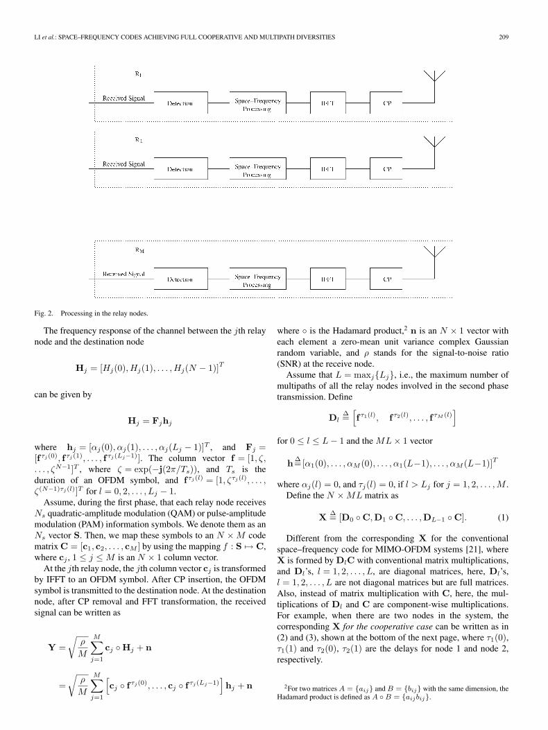
Two protocols are commonly assumed [3], [4]: One isamplify-and-forward, and the other is decode-and-forward. Inthe amplify-and-forward protocol, the relay nodes just forwardthe noisy signal they received to the destination node. In thedecode-and-forward protocol, the relay nodes first detect theinformation sent by the source node, and if there is no errorin the detected information (by using error detection code, suchas cyclic redundancy check (CRC) [20]), the relay nodes thenremodulate these information symbols and send the remodu-lated signal to the destination node. In this paper, we adoptthe decode-and-forward protocol and only consider relay nodesthat have no errors occurring in their first phase. In the secondphase, the relays use the OFDM modulation scheme, as shownin Fig. 2. The detected symbols are firstly parsed into blocksof length N . Then, we apply N point inverse fast Fouriertransform (IFFT) to these blocks. An IFFT transformed symbolblock is called an OFDM symbol. Before transmitting, thecyclic prefix (CP) is added to each OFDM symbol. At the desti-nation node, after CP removal, the received OFDM symbols arefast Fourier transform (FFT), and the resulting symbols are usedfor detection. As a note, in [27], another protocol for frequency-selective fading channels is considered, where a relay node doesnot need to implement FFT/IFFT or decode.
B. Receive Signal Model
Without loss of generality, we assume that all M relay nodes1
have correctly detected the information symbols in their firstphase. Thus, in the second phase, all the M relays are involvedin the transmission. The channel impulse response from therelay node j to the receive node is denoted as
hj(τ) =Lj−1∑l=0
αj(l)δ (τ − τj(l))
where Lj is the number of multipaths for relay node j. Thecomplex amplitude and delay for the lth multipath of relaynode j are αj(l) and τj(l), respectively, where αj(l) is a zero-mean complex Gaussian variable with power E[|αj(l)|2] =σ2
j (l). The coefficients αj(l) for different j and l, where1 ≤ j ≤ M and 0 ≤ l ≤ Lj − 1, are assumed independent.
The total power is normalized such that∑Lj−1
l=0 σ2j (l) = 1 for
j = 1, 2, . . . ,M . We further assume that the delays for therelay nodes are rounded to the sampling position, i.e., τj(l) is amultiple of 1/Fs, where Fs is the sampling frequency.
Different from conventional MIMO systems, the power delayprofile for different relays can be different in user-cooperativecommunications. This is because, in user-cooperative commu-nications, the relay nodes may be in a quite different environ-ment, whereas in conventional MIMO systems, the antennas arecolocated, and thus, the power delay profiles are assumed to bethe same for all antennas.
1The code is designed based on the assumption that there are M relay nodes.If the actual involved number of relay nodes is less than M , the designedcode can still achieve full cooperative and multipath diversities, where fullcooperative diversity means full cooperative diversity with all the active relaynodes.
LI et al.: SPACE–FREQUENCY CODES ACHIEVING FULL COOPERATIVE AND MULTIPATH DIVERSITIES 209
Fig. 2. Processing in the relay nodes.
The frequency response of the channel between the jth relaynode and the destination node
Hj = [Hj(0),Hj(1), . . . , Hj(N − 1)]T
can be given by
Hj = Fjhj
where hj = [αj(0), αj(1), . . . , αj(Lj − 1)]T , and Fj =[fτj(0), fτj(1), . . . , fτj(Lj−1)]. The column vector f = [1, ζ,. . . , ζN−1]T , where ζ = exp(−j(2π/Ts)), and Ts is theduration of an OFDM symbol, and fτj(l) = [1, ζτj(l), . . . ,ζ(N−1)τj(l)]T for l = 0, 2, . . . , Lj − 1.
Assume, during the first phase, that each relay node receivesNs quadratic-amplitude modulation (QAM) or pulse-amplitudemodulation (PAM) information symbols. We denote them as anNs vector S. Then, we map these symbols to an N × M codematrix C = [c1, c2, . . . , cM ] by using the mapping f : S �→ C,where cj , 1 ≤ j ≤ M is an N × 1 column vector.
At the jth relay node, the jth column vector cj is transformedby IFFT to an OFDM symbol. After CP insertion, the OFDMsymbol is transmitted to the destination node. At the destinationnode, after CP removal and FFT transformation, the receivedsignal can be written as
Y =√
ρ
M
M∑j=1
cj ◦ Hj + n
=√
ρ
M
M∑j=1
[cj ◦ fτj(0), . . . , cj ◦ fτj(Lj−1)
]hj + n
where ◦ is the Hadamard product,2 n is an N × 1 vector witheach element a zero-mean unit variance complex Gaussianrandom variable, and ρ stands for the signal-to-noise ratio(SNR) at the receive node.
Assume that L = maxj{Lj}, i.e., the maximum number ofmultipaths of all the relay nodes involved in the second phasetransmission. Define
DlΔ=
[fτ1(l), fτ2(l), . . . , fτM (l)
]for 0 ≤ l ≤ L − 1 and the ML × 1 vector
h Δ=[α1(0), . . . , αM (0), . . . , α1(L−1), . . . , αM (L−1)]T
where αj(l) = 0, and τj(l) = 0, if l > Lj for j = 1, 2, . . . ,M .Define the N × ML matrix as
X Δ= [D0 ◦ C,D1 ◦ C, . . . ,DL−1 ◦ C]. (1)
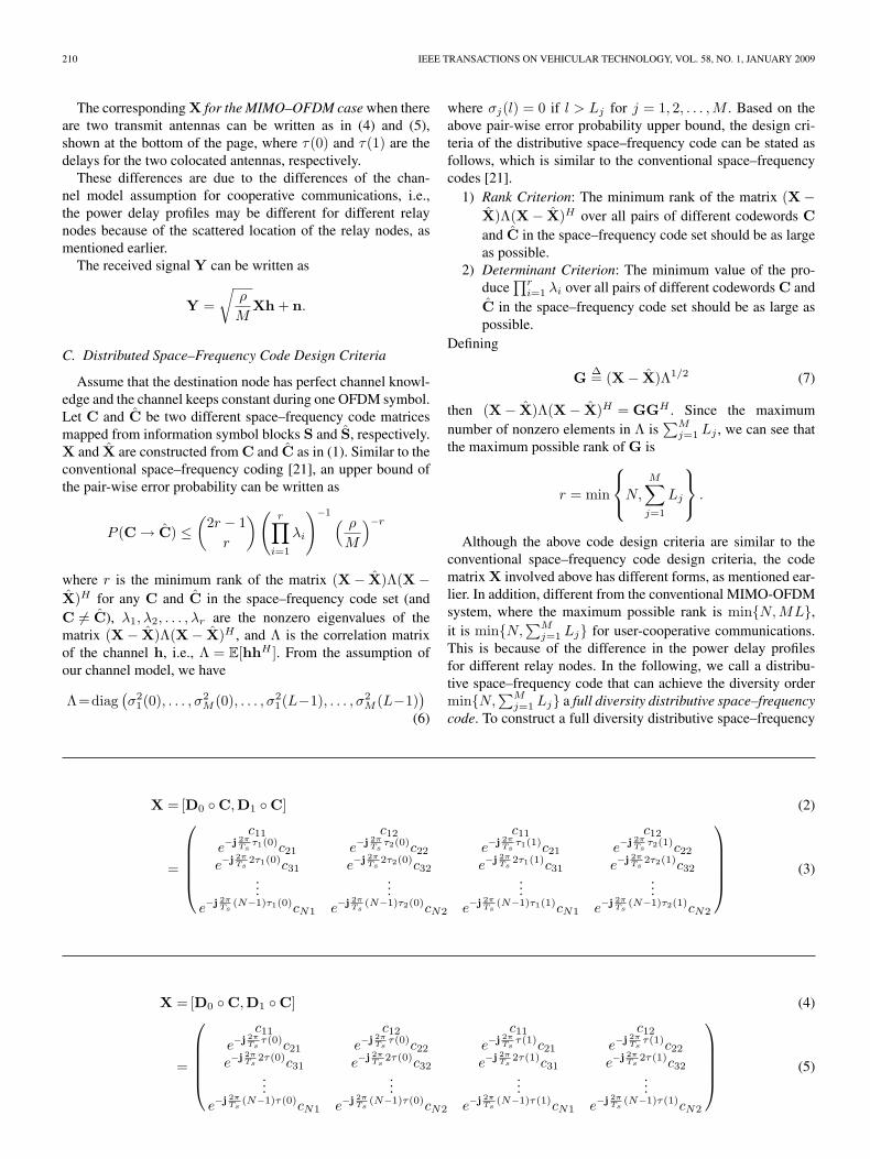
Different from the corresponding X for the conventionalspace–frequency code for MIMO-OFDM systems [21], whereX is formed by DlC with conventional matrix multiplications,and Dl’s, l = 1, 2, . . . , L, are diagonal matrices, here, Dl’s,l = 1, 2, . . . , L are not diagonal matrices but are full matrices.Also, instead of matrix multiplication with C, here, the mul-tiplications of Dl and C are component-wise multiplications.For example, when there are two nodes in the system, thecorresponding X for the cooperative case can be written as in(2) and (3), shown at the bottom of the next page, where τ1(0),τ1(1) and τ2(0), τ2(1) are the delays for node 1 and node 2,respectively.
2For two matrices A = {aij} and B = {bij} with the same dimension, theHadamard product is defined as A ◦ B = {aijbij}.
210 IEEE TRANSACTIONS ON VEHICULAR TECHNOLOGY, VOL. 58, NO. 1, JANUARY 2009
The corresponding X for the MIMO–OFDM case when thereare two transmit antennas can be written as in (4) and (5),shown at the bottom of the page, where τ(0) and τ(1) are thedelays for the two colocated antennas, respectively.
These differences are due to the differences of the chan-nel model assumption for cooperative communications, i.e.,the power delay profiles may be different for different relaynodes because of the scattered location of the relay nodes, asmentioned earlier.
The received signal Y can be written as
Y =√
ρ
MXh + n.
C. Distributed Space–Frequency Code Design Criteria
Assume that the destination node has perfect channel knowl-edge and the channel keeps constant during one OFDM symbol.Let C and C be two different space–frequency code matricesmapped from information symbol blocks S and S, respectively.X and X are constructed from C and C as in (1). Similar to theconventional space–frequency coding [21], an upper bound ofthe pair-wise error probability can be written as
P (C → C) ≤(
2r − 1r
)(r∏
i=1
λi
)−1 ( ρ
M
)−r
where r is the minimum rank of the matrix (X − X)Λ(X −X)H for any C and C in the space–frequency code set (andC �= C), λ1, λ2, . . . , λr are the nonzero eigenvalues of thematrix (X − X)Λ(X − X)H , and Λ is the correlation matrixof the channel h, i.e., Λ = E[hhH ]. From the assumption ofour channel model, we have
Λ=diag(σ2
1(0), . . . , σ2M (0), . . . , σ2
1(L−1), . . . , σ2M (L−1)
)(6)
where σj(l) = 0 if l > Lj for j = 1, 2, . . . ,M . Based on theabove pair-wise error probability upper bound, the design cri-teria of the distributive space–frequency code can be stated asfollows, which is similar to the conventional space–frequencycodes [21].
1) Rank Criterion: The minimum rank of the matrix (X −X)Λ(X − X)H over all pairs of different codewords Cand C in the space–frequency code set should be as largeas possible.
2) Determinant Criterion: The minimum value of the pro-duce
∏ri=1 λi over all pairs of different codewords C and
C in the space–frequency code set should be as large aspossible.
Defining
G Δ= (X − X)Λ1/2 (7)
then (X − X)Λ(X − X)H = GGH . Since the maximumnumber of nonzero elements in Λ is
∑Mj=1 Lj , we can see that
the maximum possible rank of G is
r = min
⎧⎨⎩N,
M∑j=1
Lj
⎫⎬⎭ .
Although the above code design criteria are similar to theconventional space–frequency code design criteria, the codematrix X involved above has different forms, as mentioned ear-lier. In addition, different from the conventional MIMO-OFDMsystem, where the maximum possible rank is min{N,ML},it is min{N,
∑Mj=1 Lj} for user-cooperative communications.
This is because of the difference in the power delay profilesfor different relay nodes. In the following, we call a distribu-tive space–frequency code that can achieve the diversity ordermin{N,
∑Mj=1 Lj} a full diversity distributive space–frequency
code. To construct a full diversity distributive space–frequency
X = [D0 ◦ C,D1 ◦ C] (2)
=
⎛⎜⎜⎜⎜⎝
c11 c12 c11 c12
e−j 2πTs
τ1(0)c21 e−j 2πTs
τ2(0)c22 e−j 2πTs
τ1(1)c21 e−j 2πTs
τ2(1)c22
e−j 2πTs
2τ1(0)c31 e−j 2πTs
2τ2(0)c32 e−j 2πTs
2τ1(1)c31 e−j 2πTs
2τ2(1)c32...
......
...e−j 2π
Ts(N−1)τ1(0)cN1 e−j 2π
Ts(N−1)τ2(0)cN2 e−j 2π
Ts(N−1)τ1(1)cN1 e−j 2π
Ts(N−1)τ2(1)cN2
⎞⎟⎟⎟⎟⎠ (3)
X = [D0 ◦ C,D1 ◦ C] (4)
=
⎛⎜⎜⎜⎜⎝
c11 c12 c11 c12
e−j 2πTs
τ(0)c21 e−j 2πTs
τ(0)c22 e−j 2πTs
τ(1)c21 e−j 2πTs
τ(1)c22
e−j 2πTs
2τ(0)c31 e−j 2πTs
2τ(0)c32 e−j 2πTs
2τ(1)c31 e−j 2πTs
2τ(1)c32...
......
...e−j 2π
Ts(N−1)τ(0)cN1 e−j 2π
Ts(N−1)τ(0)cN2 e−j 2π
Ts(N−1)τ(1)cN1 e−j 2π
Ts(N−1)τ(1)cN2
⎞⎟⎟⎟⎟⎠ (5)
LI et al.: SPACE–FREQUENCY CODES ACHIEVING FULL COOPERATIVE AND MULTIPATH DIVERSITIES 211
code, it is sufficient to construct a codeword set that can guar-antee rank min{N,ML} for X − X over all pairs of differentspace–frequency codewords C and C in the space–frequencycode set, as stated in the following lemma.
Lemma 1: If X − X has rank min{N,ML}, where L =maxj{Lj}, then for Λ defined in (6), the matrix G = (X −X)Λ1/2 has rank min{N,
∑Mj=1 Lj}.
Proof:1) If N <
∑Mj=1 Lj , select N columns from X − X, where
their corresponding δj(l) in matrix Λ is nonzero. De-noting the selected matrix as ΔX and their corre-sponding δj(l) in a diagonal matrix as Λ′1/2, thenwe have rank((X − X)Λ1/2) ≥ rank(ΔXΛ′1/2) = N ,whereas rank((X − X)Λ1/2) ≤ N . Thus, rank((X −X)Λ1/2) = N = min{N,
∑Mj=1 Lj}.
2) If N >∑M
j=1 Lj , select the columns from X − Xwhere their corresponding δj(l) �= 0 ∀l, j, 1 ≤ l ≤ Lj ,and j = 1, 2, . . . ,M . Denote the selected matrix asΔX and the corresponding nonzero elements in Λ1/2
as Λ′1/2. Then, ΔXΛ′1/2 = (X − X)Λ1/2. Thus,rank((X − X)Λ1/2) = rank(ΔXΛ′1/2)) =
∑Mj=1 Lj =
min{N,∑M
j=1 Lj}. �
III. CODE CONSTRUCTION
In this section, we propose the construction of a high-ratedistributive space–frequency code that can achieve full diversity∑M
j=1 Lj , which includes both full relay cooperative diversityM and full multipath diversity Lj . Based on Lemma 1, it isenough to construct a high-rate space–frequency codeword setsuch that the corresponding X − X has rank min{N,ML} forevery different C and C in the codeword set. The followingconstruction is the same as the space–frequency code presentedin [25] when the time block size Mb = 1 for MIMO-OFDMsystems, where the full MIMO diversity property was shown.As we shall show later, this code also achieves full cooperativeand multipath diversities for asynchronous cooperative commu-nications. As a note, a similar construction of high-rate fullMIMO diversity space–frequency code was proposed in [26]for MIMO-OFDM systems.
Suppose that, during the first phase, each relay node receivesNs = NM symbols from the source node, where each symbolis an element in a QAM or PAM constellation. We denote thealphabet set of the constellation as C; thus, the informationsymbol vector S ∈ CNs . Assume that the Ns symbols aredivided into J subblocks with KM symbols in each subblock,where JK = N , and K = 2�log2 M�+�log2 L�. Each subblock is
encoded into a space–frequency matrix Bi of size K × M fori = 1, 2, . . . , J . The space–frequency code C is constructedfrom Bi as
C =
⎛⎜⎜⎝
B1
B2...
BJ
⎞⎟⎟⎠ . (8)
Defining NL = 2�log2 L� and NM = 2�log2 M�, clearly, K =NLNM . The K × M matrix Bi has the following structure:
Bi =
⎛⎜⎜⎝
A1
A2...
ANL
⎞⎟⎟⎠ (9)
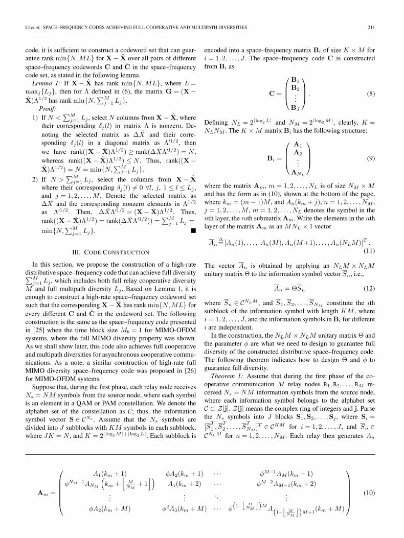
where the matrix Am, m = 1, 2, . . . , NL is of size NM × Mand has the form as in (10), shown at the bottom of the page,where km = (m − 1)M , and An(km + j), n = 1, 2, . . . , NM ,j = 1, 2, . . . ,M , m = 1, 2, . . . , NL denotes the symbol in thenth layer, the mth submatrix Am. Write the elements in the nthlayer of the matrix Am as an MNL × 1 vector
AnΔ=[An(1), . . . , An(M), An(M+1), . . . , An(NLM)]T .
(11)
The vector An is obtained by applying an NLM × NLMunitary matrix Θ to the information symbol vector Sn, i.e.,
An = ΘSn (12)
where Sn ∈ CNLM , and S1, S2, . . . , SNMconstitute the ith
subblock of the information symbol with length KM , wherei = 1, 2, . . . , J , and the information symbols in Bi for differenti are independent.
In the construction, the NLM × NLM unitary matrix Θ andthe parameter φ are what we need to design to guarantee fulldiversity of the constructed distributive space–frequency code.The following theorem indicates how to design Θ and φ toguarantee full diversity.
Theorem 1: Assume that during the first phase of the co-operative communication M relay nodes R1, R2, . . . , RM re-ceived Ns = NM information symbols from the source node,where each information symbol belongs to the alphabet setC ⊂ Z[j]. Z[j] means the complex ring of integers and j. Parsethe Ns symbols into J blocks S1,S2, . . . ,Sj , where Si =[S
T1 , S
T2 , . . . , S
TNM
]T ∈ CKM for i = 1, 2, . . . , J , and Sn ∈CNLM for n = 1, 2, . . . , NM . Each relay then generates An
Am =
⎛⎜⎜⎜⎜⎜⎝
A1(km + 1) φA2(km + 1) · · · φM−1AM (km + 1)φNM−1ANM
(km +
⌊M
NM+ 1
⌋)A1(km + 2) · · · φM−2AM−1(km + 2)
......
. . ....
φA2(km + M) φ2A3(km + M) · · · φ
(1−
⌊M
NM
⌋)M
A(1−
⌊M
NM
⌋)M+1
(km + M)
⎞⎟⎟⎟⎟⎟⎠ (10)
212 IEEE TRANSACTIONS ON VEHICULAR TECHNOLOGY, VOL. 58, NO. 1, JANUARY 2009
[defined in (11)] according to (12) for n = 1, 2, . . . , NM andthen assembles these vectors to form matrix Am for m =1, 2, . . . , NL. The distributive space–frequency code C consistsof matrices Bi, i = 1, 2, . . . , J , as in (8), and Bi consists ofAm, m = 1, 2, . . . , NL, as in (9). During the second phase,the jth relay transforms the jth column of C by IFFT. Afteradding the CP, the transformed symbols are sent to the desti-nation node. Let the MNL × MNL matrix Θ, which is usedto construct An in (12), be the first principal MNL × MNL
submatrix of the matrix
Θ = FHM
diag(1, ϕ, . . . , ϕM−1) (13)
where M = 2�log2 MNL�, ϕ = ej(2π/4M), and
φ = θ1/NM
where θ is an algebraic element with degree at least NMNL
over K, and K is the extension field of Q, which contains all theentries of Θ, the signal alphabet3 C ∈ Z[j] and e−j2π(1/N), andFM is the M × M discrete Fourier transform (DFT) matrix.Then, the constructed distributive space–frequency code hasfull diversity order
∑Mj=1 Lj , and the symbol rate of the code is
M per channel use (pcu).Proof: To prove this theorem, we need the following
lemma, which is provided in [29].Lemma 2: Let M = 2b for a positive integer b, ϕ =
ej(2π/4M), FM be the M × M DFT matrix, and the unitarymatrix Θ is constructed as
Θ = FHM
diag(1, ϕ, . . . , ϕM−1).
If the elements of the length M vector s and s are carvedfrom the lattice Z[j], and s �= s, then x = Θ(s − s) has no zeroentries.
Now, let us prove the preceding theorem. The proof can becarried out similarly as that in [25], [26], and [28], and thedifference here comes from the difference in the constructionof X in (1). The only difference with the proof in [25] isthe form Di ◦ ΔC with a full matrix Di and component-wisemultiplication that is different from the form DiΔC with adiagonal matrix Di and the conventional matrix multiplicationin [25]. However, this difference does not essentially affect theproof since each component in each matrix Di has a single termalthough it is a full matrix, and the products in both Di ◦ ΔCwhen Di is full in this paper and DiΔC when Di is diagonalin [25] do not include cross terms of the difference matrix ΔC.The other difference is that since it is difficult for the transmitterto know the delay of each multipath a priori, we cannot includethe parameter τj(l) in the construction; thus, we assume thatK contains e−j2π(1/N), where N is the length of the OFDMsymbol. Note that e−j2π(1/N) has the smallest power amongall the possible e−j2π(τj(l)/Ts). Furthermore, it is not hard to
3In fact, as long as field K contains j and integers, it contains all elementsin Z[j] and, thus, all elements in C. Thus, as long as N is a multiple of 4, Kcontains j since it is assumed that K contains e−j2π(1/N). In this case, theassumption that K contains all elements in C is implied by others and is notnecessary.
see that all e−j2π(τj(l)/Ts) are some powers of e−j2π(1/N).Therefore, K contains all e−j2π(τj(l)/Ts). For completeness, weinclude the proof as follows.
Obviously, we can see that the rate of the space–frequencycode is M pcu.
To prove the full diversity of the space–frequency code,based on Lemma 1, we only need to show that for any pair ofdifferent codewords C and C, the matrix X − X constructedfrom C and C has rank r = ML.
For two different codewords C and C, there exists atleast one corresponding submatrix Bi and Bi, where i ∈{1, 2, . . . , J}, such that Bi �= Bi. Otherwise, C = C. DefiningΔC = C − C, and ΔX = X − X, then the matrix ΔX can bewritten as
ΔX = [D0 ◦ ΔC,D1 ◦ ΔC, . . . ,DL−1 ◦ ΔC].
Denote ΔBi = Bi − Bi, where Bi and Bi correspond to thesubmatrices of C and C such that Bi �= Bi. We can write thecorresponding submatrix of ΔX as
ΔXi = [D0,i ◦ ΔBi,D1,i ◦ ΔBi, . . . ,DL−1,i ◦ ΔBi]
where Dl,i = [fτ1(l)i , fτ2(l)
i , . . . , fτM (l)i ], and fi =
ζ(i−1)K [1, ζ, . . . , ζK−1]T . To prove that the N × MLmatrix ΔX has rank ML, it is enough to show that theK × ML submatrix ΔXi of ΔX has rank r = ML. Based onthe structure of Bi in (9), we have
ΔXi =
⎛⎜⎜⎝
D0,i,1 ◦ ΔA1 · · · DL−1,i,1 ◦ ΔA1
D0,i,2 ◦ ΔA2 · · · DL−1,i,2 ◦ ΔA2
.... . .
...D0,i,NL
◦ ΔANL· · · DL−1,i,NL
◦ ΔANL
⎞⎟⎟⎠
where Dl,i,p = [ fτ1(l)i,p fτ2(l)
i,p · · · fτM (l)i,p
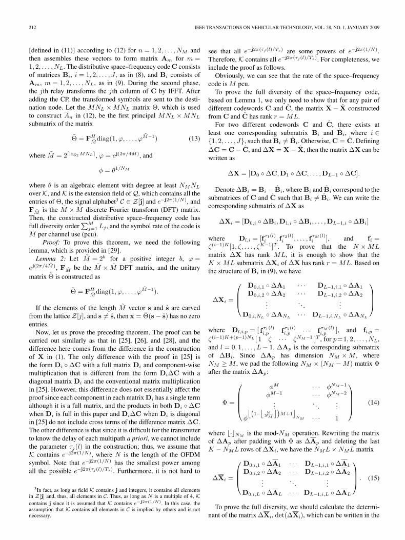
], and fi,p =ζ(i−1)K+(p−1)NL [ 1 ζ · · · ζNM−1 ]T , for p=1, 2, . . . , NL,and l = 0, 1, . . . , L − 1. ΔAp is the corresponding submatrixof ΔBi. Since ΔAp has dimension NM × M , whereNM ≥ M , we pad the following NM × (NM − M) matrix Φafter the matrix ΔAp:
Φ =
⎛⎜⎜⎜⎝
φM · · · φNM−1
φM−1 · · · φNM−2
.... . .
...
φ
⌊(1−
⌊M
NM
⌋)M+1
⌋NM · · · 1
⎞⎟⎟⎟⎠ (14)
where �·�NMis the mod-NM operation. Rewriting the matrix
of ΔAp after padding with Φ as ΔAp and deleting the lastK − NML rows of ΔXi, we have the NML × NML matrix
ΔXi =
⎛⎜⎜⎝
D0,i,1 ◦ ΔA1 · · · DL−1,i,1 ◦ ΔA1
D0,i,2 ◦ ΔA2 · · · DL−1,i,2 ◦ ΔA2
.... . .
...D0,i,L ◦ ΔAL · · · DL−1,i,L ◦ ΔAL
⎞⎟⎟⎠ . (15)
To prove the full diversity, we should calculate the determi-nant of the matrix ΔXi, det(ΔXi), which can be written in the
LI et al.: SPACE–FREQUENCY CODES ACHIEVING FULL COOPERATIVE AND MULTIPATH DIVERSITIES 213
following form:
det(ΔXi) =∑
σ
ε
(NM L∏k=1
xk,σ(k)
)
where xk,σ(k) is the (k, σ(k))th element of ΔXi, σ(k) ∈{1, 2, . . . , NML}, and σ is a permutation of the set{1, 2, . . . , NML}, and the sum is taken over all (NML)! per-mutations. ε ∈ {+1,−1}, whose value depends on the permu-tation of k. In the following, we care about the exponent of θin the summation. From the structure of Am in (10) and thestructure of ΔXi in (15), we can see that the smallest value ofthe exponent of θ in
∏NM Lk=1 xk,σ(k) is 0, which happens at the
first layer, and∏NM L
k=1 xk,σ(k) has the format
NM L∏k=1
xk,σ(k) = ζf1
L∏m=1
M∏j=1
ΔA1(km + j)
where ΔA1(kM + j) for m = 1, 2, . . . , L and j = 1, 2, . . . ,Mare the corresponding entries in matrices ΔAm, ζ = e−j(2π/Ts)
and fσ =∑L−1
l=1
∑Mj=1 αjlτj(l), where σ = 1, i.e., σ(k) = k,
and αjl is the number of times that τj(l) appears in thesummation. Since we assumed that τj(l) has been roundedto its nearest sampling time, (fσ/Ts) should be integer timesof (1/N).
In addition, it can be seen that the largest value of theexponent of θ in
∏NM Li=1 xi,σ(i) is (NM − 1)L. It happens at
the layer NM , which has the product
NM L∏k=1
xk,σ(k) = θP−1ζfNM
L∏m=1
M∏j=1
ΔANM(km + j)
where PΔ= (NM − 1)L + 1. Note that NL ≥ L. Thus, the
above degree of θ is not higher than NMNL.For other values of the exponent of θ in
∏NM Li=1 xi,σ(i), if the
product only spans on one layer, namely, the nth layer, it hasthe format
NM L∏k=1
xk,σ(k) = θ(n−1)Lζfn
L∏m=1
M∏j=1
ΔAn(km + j).
If the product spans over multiple layers, it has the format
NM L∏k=1
xk,σ(k) = θsζfσ
L∏m=1
M∏j=1
ΔAnσ(m,j)(km + j)
where nσ(m, j) ∈ {1, 2, . . . , NM}, and s = a/NM , where a isan integer. In the following, we show for ΔXi in (15), Am in(10), and the padding matrix Φ in (14) that the exponent s isalso an integer. Define the operator that takes the exponent ofθ in xij as expθ(xij). We can see that for a given row i0 or agiven column j0, the summation of the exponent of θ is
LNM∑i=1
expθ(xij0) =LNM∑j=1
expθ(xi0j)
= L
NM∑k=1
k − 1NM
=L(NM − 1)
2.
In addition, for a given column j0, we have
�NM (expθ(xi1,j0) − expθ(xi2,j0))�NM= �i2 − i1�NM
.
Therefore, we have (16)–(18), shown at the bottom of thepage. In the previous derivation, the property �a + b�NM
=��a�NM
+ �b�NM�NM
for integers a and b and the summationof the exponent for one row are used.
Thus, we can write the format of det(ΔXi) as
det(ΔXi) = ε1U1 + ε2U2θ + · · · + εP UP θP−1
where
U1 = ζf1
L∏m=1
M∏j=1
ΔA1(km + j)
UP = ζfNM
L∏m=1
M∏j=1
ΔANM(km + j)
and the other terms contain the entries of the matrix ΔXi frommultiple layers and can be written as
Up = ζfσ
L∏m=1
M∏j=1
ΔAnσ(m,j)(km + j)
where p = 2, . . . , P − 1, and nσ(m, j) ∈ {1, 2, . . . , NM}.
�a�NM=
⌊NM
(expθ
(NM L∏k=1
xk,σ(k)
))⌋NM
=
⌊NM
NM L∑k=1
expθ
(xk,σ(k)
)⌋NM
(16)
=
⌊NM
(L(NM − 1)
2−
NM L−1∑k=1
expθ
(xNM L,σ(k)
)+
NM L−1∑k=1
expθ(xk,σ(k))
)⌋NM
(17)
=
⎢⎢⎢⎣⌊NML(NM − 1)
2
⌋NM
+
⌊NM L−1∑
k=1
�NML − k�NM
⌋NM
⎥⎥⎥⎦NM
= �NML(NM − 1)�NM= 0 (18)
214 IEEE TRANSACTIONS ON VEHICULAR TECHNOLOGY, VOL. 58, NO. 1, JANUARY 2009
In our construction, θ is an algebraic element with degree atleast NMNL over K, and K is the extension field of Q thatcontains all the entries of Θ, the signal alphabet, and ζτj(l)
for j = 1, 2, . . . ,M and l = 0, 1, . . . , L − 1. Since the valueof the determinant is taken for Si, Si ∈ CKM and Si �= Si,where C ⊂ Z[j]. So there exists at least one layer n such that
Sn − Sn �= 0. From Lemma 2, we have ΔAn(km + j) �= 0 form = 1, 2, . . . , NL and j = 1, 2, . . . ,M .
Supposing that there are N0 nonzero layers, denote theirindex in increasing order as I1, I2, . . . , IN0 . We now show byinduction that if N0 ≥ 1, then det(ΔXi) �= 0.
1) If there is only one layer that is nonzero, assume it is n.Then, because of the nonzero of ΔAn(kM + j) �= 0 form = 1, 2, . . . , NL and j = 1, 2, . . . ,M , we have
det(ΔXi) = εθ(n−1)LL∏
m=1
M∏j=1
ΔAn(km + j) �= 0.
2) If there are N0 − 1 nonzero layers, assume that the de-terminant det(ΔXi) �= 0. Denote the determinant in thiscase as
det(ΔXi(I1, I2, . . . , IN0−1)
)�= 0.
3) Then, if there are N0 nonzero layers, the determinant inthis case can be written as
det(ΔXi(I1, I2, . . . , IN0)
)= ε1U1 + · · · + εP ′UP ′θP ′−1
where P ′ = (IN0 − 1)L + 1. Since the degree ofθ is at least NMNL > P ′ − 1, we have UP ′ =ζfNM
∏Lm=1
∏Mj=1 ΔAIN0
(km + j) = 0. Based on
Lemma 2, this indicates that SIN0− SIN0
= 0, i.e., theIN0 th layer is a zero layer, which contradicts with theassumption.
Thus, we have det(ΔX) �= 0, and the constructed space–frequency code has the full diversity. �
A. Properties of the Distributive Space–Frequency Code
We next see some properties of the proposed code.1) Insensitive to Timing Errors: In user cooperative com-
munications, because each transceiver has its own oscillator, itis difficult to keep these relay nodes synchronized. In additionto this, because the relays are scattered in different areas,the propagation delays for different relay nodes can be quitedifferent. This also causes the timing errors.
For the constructed distributive space–frequency code inTheorem 1, we have the following corollary.
Corollary 1: Assume that the timing error for the relaynode Rj is τ j for j = 1, 2, . . . ,M , which is rounded to thenearest sampling position. For the constructed distributivespace–frequency code in Theorem 1, if the length of the CPadded to the OFDM symbol is not less than maxj,l{τ j +τj(l)}, then the code can still achieve the full diversity order∑M
j=1 Lj .
Proof: Because the CP is not less than the maximumdelay in the channel, we can still maintain orthogonality be-tween the subcarriers. Thus, the uncertain delay of the channelin the time domain can be transformed to be the phase shiftin the frequency domain. The channel for the jth relay in thefrequency domain now is
Hj = Fjhj
but now, Fj = [fτj+τj(0), fτj+τj(1), . . . , fτj+τj(Lj−1)].Following the same proof of Theorem 1, we can show that
the distributive space–frequency code has full diversity. �2) Rate Adaptivity: For the code constructed in Theorem 1,
there are NM layers, and the rate it achieves is M symbolspcu. This is the maximum rate it can achieve. To achieve thisrate, if the constellations used in the first and second phases arethe same, the time used in the first phase transmission shouldbe M times longer than that used in the second. The rate ofthe constructed space–frequency code can be adapted accord-ing to the channel quality of the first phase by adjusting thenumber of layers in the code. Generally, if there are T layers,where 1 ≤ T ≤ NM , the transmission rate of the distributivespace–frequency is
TM
NM(symbol pcu).
It can be shown that with the same construction method,the code that has T layers can also achieve full diversity order∑M
j=1 Lj .Furthermore, when the full rate is used for the code in the
second phase transmission, since this symbol rate is higher thanthe one in the first phase, a signal constellation of smaller sizecan be used in the second phase to maintain the same data rateas in the first phase.
B. Code Examples
We now see some examples.1) M = 2, L1 = L2 = 2: In this case, NM = 2 and
NL = 2, and the matrix Am in (10) can be constructed as
Am =(
A1 (2(m − 1) + 1) φA2 (2(m − 1) + 1)φA2(2m) A1(2m)
)
for m = 1, 2. The matrix Bi can be constructed as
Bi =
⎛⎜⎝
A1(1) φA2(1)φA2(2) A1(2)A1(3) φA2(3)φA2(4) A1(4)
⎞⎟⎠ (19)
where [An(1), An(2), An(3), An(4)]T = Θ[s4(n−1)+1,s4(n−1)+2, s4(n−1)+3, s4n]T for n = 1, 2, where s1, s2, . . . , s8
are the information symbols coming from QPSK constellation.
LI et al.: SPACE–FREQUENCY CODES ACHIEVING FULL COOPERATIVE AND MULTIPATH DIVERSITIES 215
Assuming that the length of the OFDM symbol is 64, then wechoose θ = e−j(π/32). In this case, Θ can be constructed as
Θ=12
⎛⎜⎝
1 1 1 11 ej π
2 ejπ ej 3π2
1 ejπ ej2π ej3π
1 ej 3π2 ej3π ej 9π
2
⎞⎟⎠
⎛⎜⎝
1 0 0 00 ej π
32 0 00 0 ej π
16 00 0 0 ej 3π
32
⎞⎟⎠ .
(20)
φ can be chosen as φ = ej(π/128). If only one layer isconsidered, then A2(1), A2(2), A2(3), and A2(4) are set to bezero, and the rate of the code becomes only 1 symbol pcu.
2) M = 4, L1 = L2 = 2: In this case, NM = 4, and NL =2. The matrix B can be constructed as
Bi =
⎛⎜⎜⎜⎜⎜⎜⎜⎜⎜⎝
A1(1) φA2(1) φ2A3(1) φ3A4(1)φ3A4(2) A1(2) φA2(2) φ2A3(2)φ2A3(3) φ3A4(3) A1(3) φA2(3)φA2(4) φ2A3(4) φ3A4(4) A1(4)A1(5) φA2(5) φ2A3(5) φ3A4(5)
φ3A4(6) A1(6) φA2(6) φ2A3(6)φ2A3(7) φ3A4(7) A1(7) φA2(7)φA2(8) φ2A3(8) φ3A4(8) A1(8)
⎞⎟⎟⎟⎟⎟⎟⎟⎟⎟⎠
where [An(1), An(2), . . . , An(8)]T=Θ[s8(n−1)+1, s8(n−1)+2,. . . , s8n]T , n = 1, 2, 3, 4. s1, s2, . . . , s32 can be chosen fromthe QPSK constellation. The parameters Θ and φ can be similaras in the case M = 2 and L1 = L2 = 2.
IV. SIMULATIONS
In this section, we simulate the performance of the con-structed distributive space–frequency code and compare it withthe concatenation of Alamouti’s scheme and the OFDM, as in[18] and [19]. For these schemes, we used ML detection. Inpractice, the sphere decoder can be used to simplify the detec-tion complexity of the proposed distributive space–frequencycode. By saying so, its complexity is still higher than theAlamouti-coded OFDM method in [18] and [19].
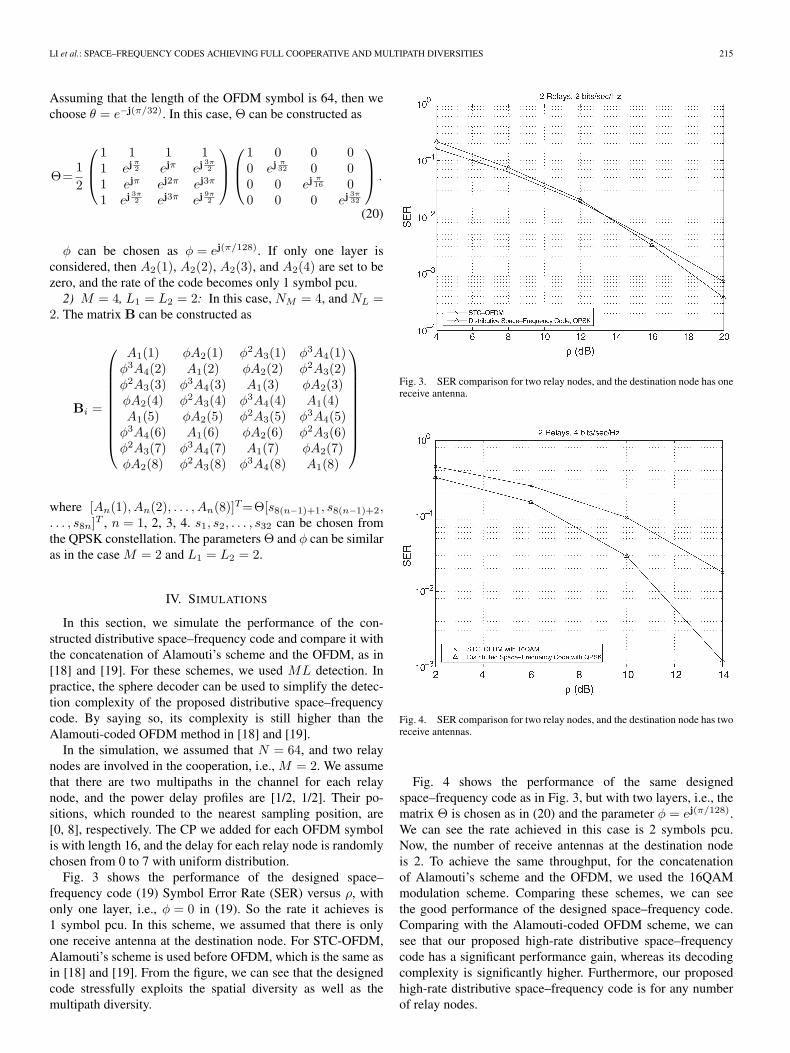
In the simulation, we assumed that N = 64, and two relaynodes are involved in the cooperation, i.e., M = 2. We assumethat there are two multipaths in the channel for each relaynode, and the power delay profiles are [1/2, 1/2]. Their po-sitions, which rounded to the nearest sampling position, are[0, 8], respectively. The CP we added for each OFDM symbolis with length 16, and the delay for each relay node is randomlychosen from 0 to 7 with uniform distribution.
Fig. 3 shows the performance of the designed space–frequency code (19) Symbol Error Rate (SER) versus ρ, withonly one layer, i.e., φ = 0 in (19). So the rate it achieves is1 symbol pcu. In this scheme, we assumed that there is onlyone receive antenna at the destination node. For STC-OFDM,Alamouti’s scheme is used before OFDM, which is the same asin [18] and [19]. From the figure, we can see that the designedcode stressfully exploits the spatial diversity as well as themultipath diversity.
Fig. 3. SER comparison for two relay nodes, and the destination node has onereceive antenna.
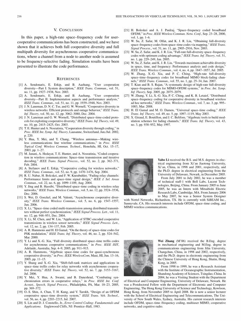
Fig. 4. SER comparison for two relay nodes, and the destination node has tworeceive antennas.
Fig. 4 shows the performance of the same designedspace–frequency code as in Fig. 3, but with two layers, i.e., thematrix Θ is chosen as in (20) and the parameter φ = ej(π/128).We can see the rate achieved in this case is 2 symbols pcu.Now, the number of receive antennas at the destination nodeis 2. To achieve the same throughput, for the concatenationof Alamouti’s scheme and the OFDM, we used the 16QAMmodulation scheme. Comparing these schemes, we can seethe good performance of the designed space–frequency code.Comparing with the Alamouti-coded OFDM scheme, we cansee that our proposed high-rate distributive space–frequencycode has a significant performance gain, whereas its decodingcomplexity is significantly higher. Furthermore, our proposedhigh-rate distributive space–frequency code is for any numberof relay nodes.
216 IEEE TRANSACTIONS ON VEHICULAR TECHNOLOGY, VOL. 58, NO. 1, JANUARY 2009
V. CONCLUSION
In this paper, a high-rate space–frequency code for user-cooperative communications has been constructed, and we haveshown that it achieves both full cooperative diversity and fullmultipath diversity for asynchronous cooperative communica-tions, where a channel from a node to another node is assumedto be frequency-selective fading. Simulation results have beenpresented to illustrate the code performance.
REFERENCES
[1] A. Sendonaris, E. Erkip, and B. Aazhang, “User cooperationdiversity—Part I: System description,” IEEE Trans. Commun., vol. 51,no. 11, pp. 1927–1938, Nov. 2003.
[2] A. Sendonaris, E. Erkip, and B. Aazhang, “User cooperationdiversity—Part II: Implementation aspects and performance analysis,”IEEE Trans. Commun., vol. 51, no. 11, pp. 1939–1948, Nov. 2003.
[3] J. N. Laneman, D. N. C. Tse, and G. W. Wornell, “Cooperative diversity inwireless networks: Efficient protocols and outage behavior,” IEEE Trans.Inf. Theory, vol. 50, no. 12, pp. 3062–3080, Dec. 2004.
[4] J. N. Laneman and G. W. Wornell, “Distributed space–time-coded proto-cols for exploiting cooperative diversity,” IEEE Trans. Inf. Theory, vol. 49,no. 10, pp. 2415–2425, Oct. 2003.
[5] T. E. Hunter and A. Nosratinia, “Cooperation diversity through coding,” inProc. IEEE Int. Symp. Inf. Theory, Lausanne, Switzerland, Jun./Jul. 2002,p. 220.
[6] Y. Hua, Y. Mei, and Y. Chang, “Wireless antennas—Making wire-less communications line wireline communications,” in Proc. IEEETopical Conf. Wireless Commun. Technol., Honolulu, HI, Oct. 15–17,2003, pp. 1–27.
[7] M. Janani, A. Hedayat, T. E. Hunter, and A. Nosratinia, “Coded coopera-tion in wireless communications: Space–time transmission and iterativedecoding,” IEEE Trans. Signal Process., vol. 52, no. 2, pp. 362–371,Feb. 2004.
[8] A. Stefanov and E. Erkip, “Cooperative coding for wireless networks,”IEEE Trans. Commun., vol. 52, no. 9, pp. 1470–1476, Sep. 2004.
[9] R. U. Nabar, H. Bolcskei, and F. W. Kneubuhler, “Fading relay channels:Performance limits and space–time signal design,” IEEE J. Sel. AreasCommun., vol. 22, no. 6, pp. 1099–1109, Aug. 2004.
[10] Y. Jing and B. Hassibi, “Distributed space–time coding in wireless relaynetworks,” IEEE Trans. Wireless Commun., vol. 5, no. 12, pp. 3524–3536,Dec. 2006.
[11] S. Wei, D. Goeckel, and M. Valenti, “Asynchronous cooperative diver-sity,” IEEE Trans. Wireless Commun., vol. 5, no. 6, pp. 1547–1557,Jun. 2006.
[12] X. Li, “Space–time coded multi-transmission among distributed transmit-ters without perfect synchronization,” IEEE Signal Process. Lett., vol. 11,no. 12, pp. 948–951, Dec. 2004.
[13] X. Li, M. Chen, and W. Liu, “Application of STBC-encoded cooperativetransmissions in wireless sensor networks,” IEEE Signal Process. Lett.,vol. 12, no. 2, pp. 134–137, Feb. 2005.
[14] A. R. Hammons and H. El Gamal, “On the theory of space–time codes forPSK modulation,” IEEE Trans. Inf. Theory, vol. 46, no. 2, pp. 524–542,Mar. 2000.
[15] Y. Li and X.-G. Xia, “Full diversity distributed space–time trellis codesfor asynchronous cooperative communications,” in Proc. IEEE ISIT,Adelaide, Australia, Sep. 4–9, 2005, pp. 911–915.
[16] A. R. Hammons, “Algebraic space–time codes for quasi-synchronouscooperative diversity,” in Proc. IEEE WirelessCom, Maui, HI, Jun. 13–16,2005, pp. 11–15.
[17] Y. Shang and X.-G. Xia, “Shift-full-rank matrices and applications inspace–time trellis codes for relay networks with asynchronous coopera-tive diversity,” IEEE Trans. Inf. Theory, vol. 52, no. 7, pp. 3153–3167,Jul. 2006.
[18] Y. Mei, Y. Hua, A. Swami, and B. Daneshrad, “Combating syn-chronization errors in cooperative relays,” in Proc. IEEE Int. Conf.Acoust., Speech, Signal Process., Philadelphia, PA, Mar. 18–23, 2005,pp. 369–372.
[19] O.-S. Shin, A. Chan, T. H. Kung, and V. Tarokh, “Design of an OFDMcooperative space–time diversity system,” IEEE Trans. Veh. Technol.,vol. 56, no. 4, pp. 2203–2215, Jul. 2007.
[20] S. Lin and D. J. Constello, Jr., Error Control Coding: Fundamentals andApplications. Englewood Cliffs, NJ: Prentice–Hall, 1983.
[21] H. Boleskei and A. J. Paulraj, “Space–frequency coded broadbandOFDM,” in Proc. IEEE Wireless Commun. Netw. Conf., Sep. 23–28, 2000,vol. 1, pp. 1–6.
[22] W. Su, Z. Safar, M. Olfat, and K. J. R. Liu, “Obtaining full-diversityspace–frequency codes from space–time codes via mapping,” IEEE Trans.Signal Process., vol. 51, no. 11, pp. 2905–2916, Nov. 2003.
[23] W. Su, Z. Safar, and K. J. R. Liu, “Full-rate full-diversity space–frequencycodes with optimum coding advantage,” IEEE Trans. Inf. Theory, vol. 51,no. 1, pp. 229–249, Jan. 2005.
[24] W. Su, Z. Safar, and K. J. R. Liu, “Towards maximum achievable diversityin space, time, and frequency: Performance analysis and code design,”IEEE Trans. Wireless Commun., vol. 4, no. 4, pp. 1847–1857, Jul. 2005.
[25] W. Zhang, X.-G. Xia, and P. C. Ching, “High-rate full-diversityspace–time–frequency codes for broadband MIMO block-fading chan-nels,” IEEE Trans. Commun., vol. 55, no. 1, pp. 25–34, Jan. 2007.
[26] T. Kian and B. S. Rajan, “A systematic design of high-rate full-diversityspace–frequency codes for MIMO-OFDM systems,” in Proc. Int. Symp.Inf. Theory, Sep. 2005, pp. 2075–2079.
[27] W. Zhang, Y. Li, X.-G. Xia, P. C. Ching, and K. B. Letaief, “Distributedspace–frequency coding for cooperative diversity in broadband wirelessad hoc networks,” IEEE Trans. Wireless Commun., vol. 7, no. 3, pp. 995–1003, Mar. 2008.
[28] H. El Gamal and M. O. Damen, “Universal space–time coding,” IEEETrans. Inf. Theory, vol. 49, no. 5, pp. 1097–1119, May 2003.
[29] X. Giraud, E. Boutillon, and J. C. Belifore, “Algebraic tools to build mod-ulation schemes for fading channels,” IEEE Trans. Inf. Theory, vol. 43,no. 3, pp. 938–952, May 1997.
Yabo Li received the B.S. and M.S. degrees in elec-trical engineering from Xi’an Jiaotong University,Xi’an, China, in 1998 and 2001, respectively, andthe Ph.D. degree in electrical engineering from theUniversity of Delaware, Newark, in December 2005.
From July 2001 to July 2002, he was a memberof technical staff-1 with Bell Labs, Lucent Tech-nologies, Beijing, China. From January 2005 to June2005, he was an Intern with Mitsubishi ElectricResearch Labs, Cambridge, MA. From January 2006to May 2007, he was a Senior System Designer
with Nortel Networks, Richardson, TX. He is currently with SiBEAM Inc.,Sunnyvale, CA. His research interests include OFDM, space–time coding, andMIMO wireless communications.
Wei Zhang (M’06) received the B.Eng. degreein mechanical engineering and M.Eng. degree incommunications engineering from Jilin University,Changchun, China, in 1998 and 2002, respectively,and the Ph.D. degree in electronic engineering fromthe Chinese University of Hong Kong, Shatin, HongKong, in 2005.
From 1998 to 1999, he was a Research Assistantwith the Institute of Oceanographic Instrumentation,Shandong Academy of Sciences, Tsingdao, China. In2004, he was a Visiting Student with the Department
of Electrical and Computer Engineering, University of Delaware, Newark. Hewas a Postdoctoral Fellow with the Department of Electronic and ComputerEngineering, The Hong Kong University of Science and Technology, Kowloon,Hong Kong, from November 2005 to April 2008. He is now a senior lecturerwith the School of Electrical Engineering and Telecommunications, The Uni-versity of New South Wales, Sydney, Australia. His current research interestsinclude OFDM, space–time /frequency coding, multiuser MIMO, cooperativenetworks, and cognitive radio.
LI et al.: SPACE–FREQUENCY CODES ACHIEVING FULL COOPERATIVE AND MULTIPATH DIVERSITIES 217
Xiang-Gen Xia (M’97–SM’00) received the B.S.degree in mathematics from Nanjing Normal Uni-versity, Nanjing, China, in 1983, the M.S. degreein mathematics from Nankai University, Tianjin,China, 1986, and the Ph.D. degree in electrical engi-neering from the University of Southern California,Los Angeles, in 1992.
From 1993 to 1994, he was a Research Scientistwith the Air Force Institute of Technology, Wright-Patterson Air Force Base, OH. From 1995 to 1996,he was a Senior/Research Staff Member with Hughes
Research Laboratories, Malibu, CA. Since September 1996, he has beenwith the Department of Electrical and Computer Engineering, University ofDelaware, Newark, where he is currently a Professor. From 2002 to 2003,he was a Visiting Professor with the Chinese University of Hong Kong,Shatin, Hong Kong, where he is currently an Adjunct Professor. He has sevenU.S. patents awarded and is the author of the book Modulated Coding forIntersymbol Interference Channels (New York: Marcel Dekker, 2000). Hiscurrent research interests include space–time coding and OFDM systems aswell as SAR and ISAR imaging of moving targets.
Dr. Xia served as a member of the Signal Processing for CommunicationsTechnical Committee and is a member of Sensor Array and Multi-channel(SAM) Technical Committees of the IEEE Signal Processing Society. He iscurrently an Associate Editor of the IEEE SIGNAL PROCESSING LETTERS,IEEE TRANSACTIONS ON VEHICULAR TECHNOLOGY, and Journal ofCommunications and Networks (JCN). He served as Associate Editor forthe IEEE TRANSACTIONS ON SIGNAL PROCESSING from 1997 to 2003,the IEEE TRANSACTIONS ON MOBILE COMPUTING from 2001 to 2004,and the EURASIP Journal of Applied Signal Processing from 2001 to 2004.He was a Guest Editor of space–time coding and its applications for theEURASIP Journal of Applied Signal Processing in March and May 2002. Hewas the General Co-Chair of ICASSP in 2005. He received the National ScienceFoundation (NSF) Faculty Early Career Development (CAREER) ProgramAward in 1997, the Office of Naval Research (ONR) Young InvestigatorAward in 1998, the Outstanding Overseas Young Investigator Award of theNational Natural Science Foundation of China in 2001, and the OutstandingJunior Faculty Award of the Engineering School of the University of Delawarein 2001.