Embed Size (px)
Citation preview
1
Distribution System Interconnection Guide
for Customer-Owned Power Production Facilities
less than 10 MW
Revision History
Revision Date Revised by Comments
11.0 6/23/2021 Valerie Paxton Major revision – Revised Section C General Layouts and Requirements to include Inspection Checklist items, added language for Energy Storage Systems (ESS), removed 2 ESS layouts. Revised Appendix C to refer to Section C. Revised Appendix D Interconnection Agreement.
10.0 10/25/2019 Steve Allmond Minor revision – Appendix F – Emergency Response Service (ERS) Application updated per program changes; revised Appendix E – Network Interconnection Specifications; made various formatting and other miscellaneous changes.
9.0 4/4/2018 Steve Allmond Major revision - changed various descriptions and formatting; expanded definitions; added narratives for clarity in explanations; updated drawings, diagrams, & configurations and equipment requirements; updated flowchart for interconnection application process; changed requirements for transfer/trip to align with PUCT; added "ahead of the meter" shared solar systems to types of interconnections.
8.0 1/31/2017 Steve Allmond Major revision - changed category limits, descriptions, formatting; reworked Definitions & Codes and Standards sections.
7.0 6/3/2016 Clayton Stice / Steve Allmond / Juan Ordonez
Minor revision - Appendix F – Emergency Response Service (ERS) Application updated per ERCOT program changes, added Appendix G - EV Connection Guide.
6.0 12/15/2015 Clayton Stice Major revision - update for NEC2014, add references for energy storage, high leg systems, update metering and downtown network sections, change category limits, general
Revision 11.0 June 23, 2021 2
updates.
5.0 12/19/2014 Brian Inocente Minor revision - added Appendix F - Emergency Response Service (ERS) Application.
4.0 10/22/2013 Clayton Stice Major revision - include all systems below 10 MW, reorganized sections to clarify process flow, added insurance requirements for systems over 500 kW, confidentiality notice and updated requirements based on proposed discussions regarding pIEEE1547.8 and pIEEE1547a.
3.0 5/15/2012 Clayton Stice / Sharon Bickford
Minor revision - update metering and code requirements and include updates to IEEE1547.4, 1547.6.
2.0 9/15/2011 Clayton Stice Stanley Consultants TX - 174
Minor revision - revised Interconnection Package and Forms; included references to Downtown Network Installations; consolidated/rearranged divisions and expanded complex metering section due to new ERCOT reporting requirements, expanded codes and references sections.
1.0 10/7/2010 Clayton Stice Stanley Consultants TX - 174
Major revision - clarified scope of document for 50 kW to <10MW; added Appendix A-Interconnection Package and Forms; included references to AE Design Criteria Guide and ESPA; added complex metering to meet ERCOT requirements, expanded definitions, codes and references sections; added hyperlinks to other web references; general rewrite and updates to all sections.
Revision 11.0 June 23, 2021 3
AUSTIN ENERGY DISTRIBUTION SYSTEM INTERCONNECTION GUIDE
FOR CUSTOMER-OWNED POWER PRODUCTION FACILITIES LESS THAN 10 MW
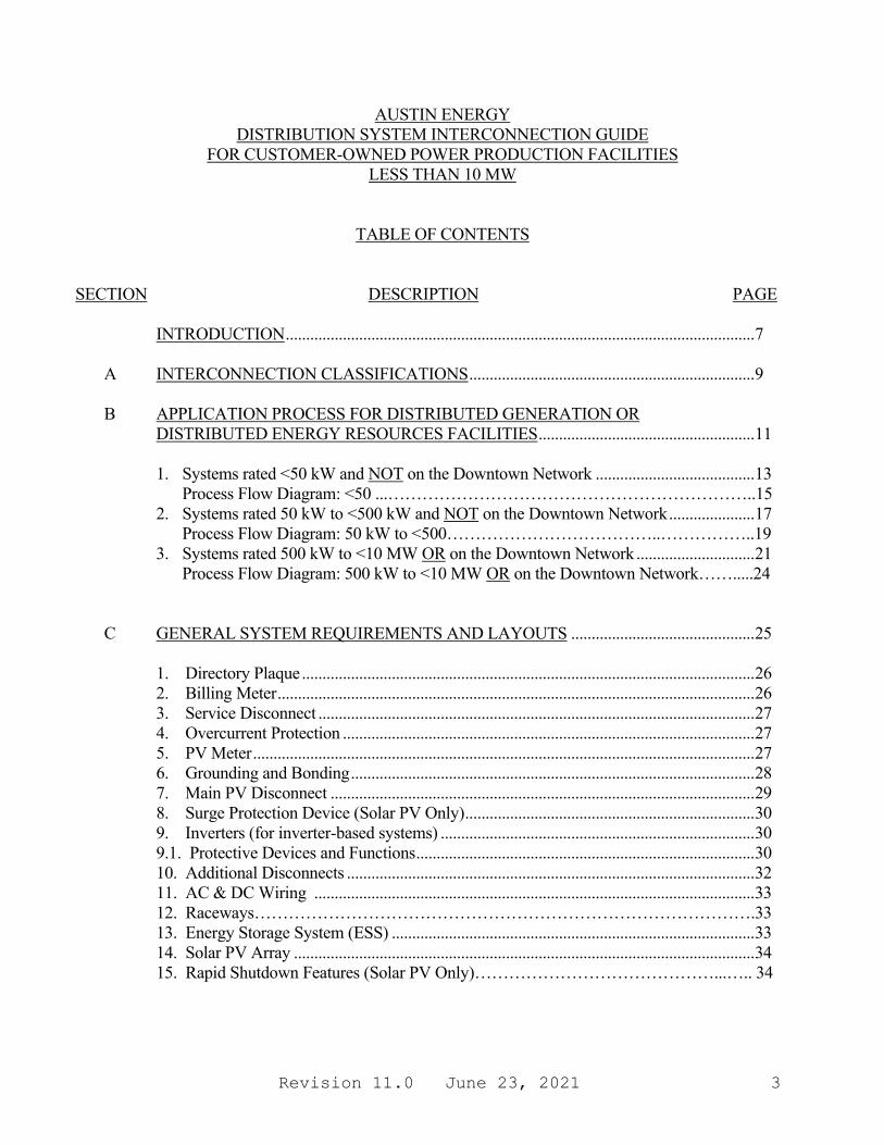
TABLE OF CONTENTS
SECTION DESCRIPTION PAGE INTRODUCTION ................................................................................................................... 7 A INTERCONNECTION CLASSIFICATIONS ...................................................................... 9 B APPLICATION PROCESS FOR DISTRIBUTED GENERATION OR
DISTRIBUTED ENERGY RESOURCES FACILITIES ..................................................... 11
1. Systems rated <50 kW and NOT on the Downtown Network ....................................... 13 Process Flow Diagram: <50 ...………………………………………………………..15
2. Systems rated 50 kW to <500 kW and NOT on the Downtown Network ..................... 17 Process Flow Diagram: 50 kW to <500………………………………..……………..19
3. Systems rated 500 kW to <10 MW OR on the Downtown Network ............................. 21 Process Flow Diagram: 500 kW to <10 MW OR on the Downtown Network…….....24
C GENERAL SYSTEM REQUIREMENTS AND LAYOUTS ............................................. 25 1. Directory Plaque ............................................................................................................... 26 2. Billing Meter ..................................................................................................................... 26 3. Service Disconnect ........................................................................................................... 27 4. Overcurrent Protection ..................................................................................................... 27 5. PV Meter ........................................................................................................................... 27 6. Grounding and Bonding ................................................................................................... 28 7. Main PV Disconnect ........................................................................................................ 29 8. Surge Protection Device (Solar PV Only) ....................................................................... 30 9. Inverters (for inverter-based systems) ............................................................................. 30 9.1. Protective Devices and Functions ................................................................................... 30 10. Additional Disconnects .................................................................................................... 32 11. AC & DC Wiring ............................................................................................................ 33 12. Raceways…………………………………………………………………………….33 13. Energy Storage System (ESS) ......................................................................................... 33 14. Solar PV Array ................................................................................................................. 34 15. Rapid Shutdown Features (Solar PV Only)……………………………………...….. 34

Revision 11.0 June 23, 2021 4
Figure 1: Simplified Diagram for Solar PV <10 kW and NOT on the Network.................................................................................................. 35 Figure 2: Simplified Diagram for AC-Coupled Solar PV plus Energy Storage <10 kW and NOT on the Network (Option 2) ................................................... 36 Figure 3: Simplified Diagram for Energy Storage Only Systems <10 kW and NOT on the Network.................................................................................................. 37 D DETAILED REQUIREMENTS FOR PARALLEL SYSTEMS ......................................... 38 1. Additional Technical Requirements by System Classification ...................................... 38 a) Systems (not on the Downtown Network) rated less than 50 kW ........................... 38 b) Systems (not on the Downtown Network) rated 50 kW to less than 1 MW ........... 38 c) Systems (not on the Downtown Network) rated 1 MW to less than 10 MW .......... 38
d) Facilities on the Downtown Network ....................................................................... 39 2. Dedicated Service ............................................................................................................. 39 3. Additional Requirements for Non-Inverter Based Generation ...................................... 39 4. Additional Requirements for Electric Energy Storage Systems .................................... 40 5. Other Protective Devices .................................................................................................. 41 6. Technical Exceptions ....................................................................................................... 41 E COMPLIANCE WITH APPLICABLE LAWS AND INSTALLATION RULES ............ 42 1. Compliance with Laws ..................................................................................................... 42 2. Compliance with Installation Rules ................................................................................. 42 3. Applicability for Emergency or Standby Systems .......................................................... 42 4. Interconnection Studies .................................................................................................... 42 5. Installation Safety ............................................................................................................. 43 6. Inspection .......................................................................................................................... 43 7. Enforcement ...................................................................................................................... 43
8. Operating Safety ............................................................................................................... 43 9. Maintenance of Protective Equipment ............................................................................ 43 10. Self-Protection .................................................................................................................. 44 11. Capital Cost Responsibility .............................................................................................. 44 12. Liability ............................................................................................................................. 44 13. Confidentiality .................................................................................................................. 44 14. Third Party Leases ............................................................................................................. 44 F DEFINITIONS ........................................................................................................................ 45 G CERTIFICATION CODES AND STANDARDS ................................................................ 49 Appendix A MAP OF THE DOWNTOWN NETWORK............................................................. 51 Appendix B STANDARD COMPLEX METER CONFIGURATIONS ..................................... 53

Revision 11.0 June 23, 2021 5
1. Figure B-1: 1P 3W 120/240V PV Meter Tap on Load Side ......................................... 54 2. Figure B-2: 1P 3W 120/240V PV Meter Tap on Line Side .......................................... 55 3. Figure B-3: 3P 4W 208/120V PV Meter Tap on Load Side ......................................... 56 4. Figure B-4: 3P 4W 208/120V PV Meter Tap on Line Side .......................................... 57 5. Figure B-5: 3P 4W 480/277V PV Meter Tap on Load Side ......................................... 58 6. Figure B-6: 3P 4W 480/277V PV Meter Tap on Line Side .......................................... 59 7. Figure B-7: 3P 4W 120/240V "High Leg" PV Meter Tap on Load Side ..................... 60
8. Figure B-8: 3P 4W 208/120V "Shared Solar Only" Tap on Line Side ........................ 61 9. Figure B-9: 3P 4W 480/277V "Shared Solar Only" Tap on Line Side ........................ 62 Appendix C AE DG/DER INSPECTION CHECKLIST .............................................................. 63 Appendix D INTERCONNECTION APPLICATION AND FORMS ......................................... 67 1. Application Checklist ....................................................................................................... 68 2. Distributed Generation/DER Application ....................................................................... 69 3. Interconnection Customer Information ........................................................................... 70 4. Distributed Generation Application for Solar PV ........................................................... 71 5. Interconnection Facilities Information ............................................................................ 72 6. Distributed Generation Application for Rotating Machines .......................................... 73 7. Interconnection Agreement .............................................................................................. 75 Appendix E NETWORK INTERCONNECTION SPECIFICATIONS ....................................... 87 1. Purpose .............................................................................................................................. 89 2. References ......................................................................................................................... 89 3. Introduction and Background .......................................................................................... 89 4. Fundamental Design Requirements ................................................................................. 90 5. Network Interconnection Requirements .......................................................................... 91 6. Control System Design Requirements ............................................................................ 92 7. Design, Installation, and Commissioning Requirements................................................ 95 8. Maintenance and Operation Requirements ..................................................................... 95 Appendix F EMERGENCY RESPONSE SERVICE (ERS) APPLICATION ............................ 97 1. ERCOT ERS Process ....................................................................................................... 99 2. ERS 3rd Party QSE Process Flowchart ........................................................................... 100 3. ERS Application Form ..................................................................................................... 101 Appendix G ELECTRIC VEHICLE CONNECTION GUIDE FOR RESIDENTIAL
CUSTOMERS ............................................................................................................ 103 1. Purpose .............................................................................................................................. 105 2. EV Charging Basics ......................................................................................................... 105 3. Connection Classifications ............................................................................................... 105
Revision 11.0 June 23, 2021 6
4. Application Processes....................................................................................................... 106 5. General System Layouts .................................................................................................. 111
Revision 11.0 June 23, 2021 7
INTRODUCTION The primary purpose of this guide is to outline the process for connecting a Distributed Generation (DG) or Distributed Energy Resources (DER) facility and to define the minimum technical and financial requirements for safe integration of customer-owned power production facilities with the Austin Energy (AE) Distribution System (Note: The typical AE Distribution System voltage is 12.47 kV). This information is provided in an effort to maintain safe and reliable service to generating facilities and customers.
This guide covers most types of Distributed Generation/Distributed Energy Resources (DG/DER) in the AE service area.
i. Inverter Based Systems - Predominantly Solar PV to date and also Energy Storage Systems (ESS)
ii. Synchronous or Induction Motor Systems - Wind generation, standard fossil-fuel based motor generators
iii. Other Types - Will be reviewed as encountered This guide is intended to be consistent with the requirements of the current version of IEEE Standard 1547, “IEEE Standard for Interconnection and Interoperability of Distributed Energy Resources with Associated Electric Power Systems Interfaces,” Federal, State, and Local regulations, and accepted industry practices and standards. It is intended as a supplement to the PUC and the IEEE for installation/interconnection of DG/DER systems on Austin Energy’s electrical distribution system. In general, the DG/DER System and associated facilities must be designed in accordance with, but not limited to, UL (Underwriters Laboratories) Standards, IEEE (Institute of Electrical and Electronics Engineers) Standards, NEC (National Electrical Code), NESC (National Electrical Safety Code), PUC (Public Utility Commission of Texas), ERCOT (Electric Reliability Council of Texas) Operating Guides and Protocols, Austin Energy Electric Service Standards and Design Criteria Manual, and any other applicable Local, State, or Federal codes or standards. Particular attention should be paid to UL 1741, UL9540, IEEE 519, and IEEE 1547. The contents of this Guide are arranged as such: Sections A-B Application Process Sections C-D Technical Requirements for Installations Section E Customer Responsibilities Sections F-G Applicable Codes and Standards and Definitions Appendices A-E References Appendix F Emergency Response Service (ERS) Applications and Form Appendix G Plug-in Electric Vehicles (PEV) paired with Time-of-Use (TOU) metering
systems Since these standards change regularly as a result of the latest practices, it is the user’s responsibility to verify that the most recent version of this document is being used.
Revision 11.0 June 23, 2021 8
The latest released version of this guide can be found on the AE website at: http://www.austinenergy.com
• Select the “Contractors” tab. • Select the “Electric Service Design & Planning" tab.
Revision 11.0 June 23, 2021 9
A. INTERCONNECTION CLASSIFICATIONS
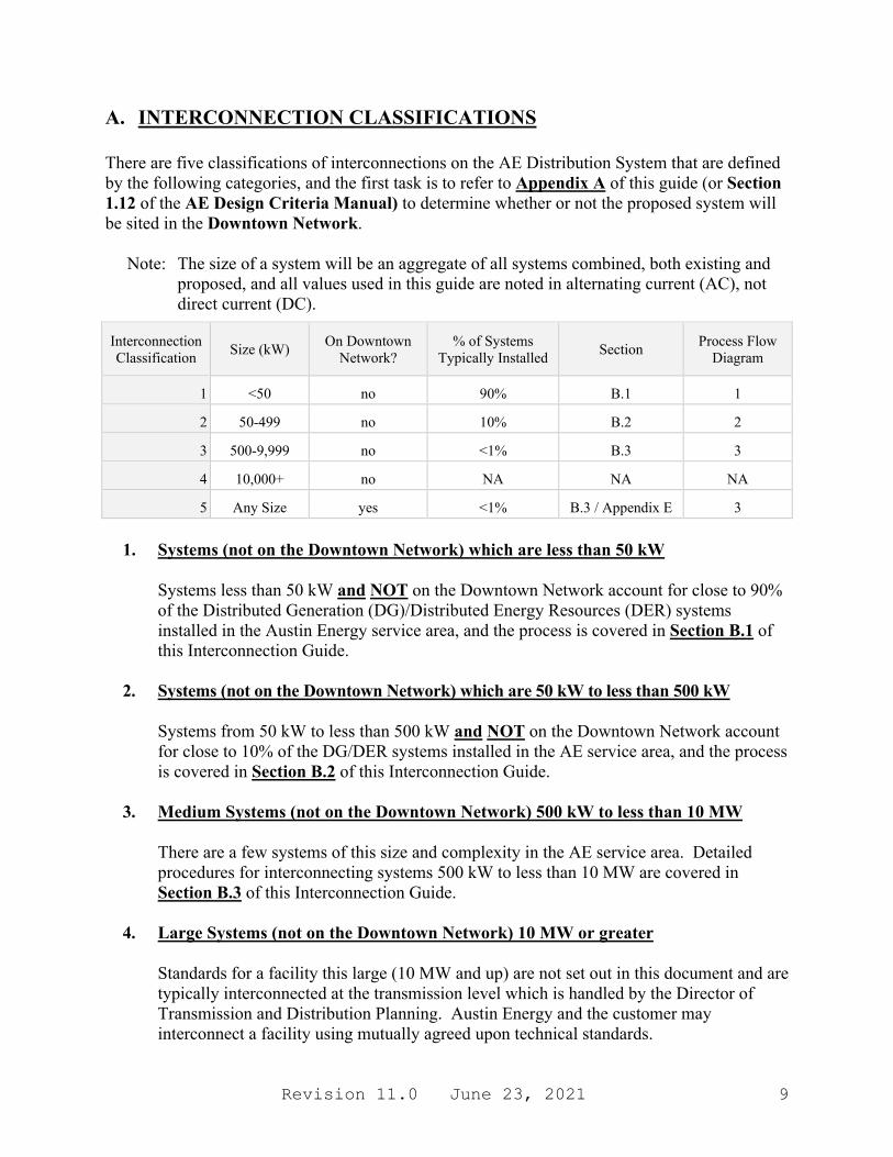
There are five classifications of interconnections on the AE Distribution System that are defined by the following categories, and the first task is to refer to Appendix A of this guide (or Section 1.12 of the AE Design Criteria Manual) to determine whether or not the proposed system will be sited in the Downtown Network. Note: The size of a system will be an aggregate of all systems combined, both existing and
proposed, and all values used in this guide are noted in alternating current (AC), not direct current (DC).
1. Systems (not on the Downtown Network) which are less than 50 kW
Systems less than 50 kW and NOT on the Downtown Network account for close to 90% of the Distributed Generation (DG)/Distributed Energy Resources (DER) systems installed in the Austin Energy service area, and the process is covered in Section B.1 of this Interconnection Guide.
2. Systems (not on the Downtown Network) which are 50 kW to less than 500 kW Systems from 50 kW to less than 500 kW and NOT on the Downtown Network account for close to 10% of the DG/DER systems installed in the AE service area, and the process is covered in Section B.2 of this Interconnection Guide.
3. Medium Systems (not on the Downtown Network) 500 kW to less than 10 MW There are a few systems of this size and complexity in the AE service area. Detailed procedures for interconnecting systems 500 kW to less than 10 MW are covered in Section B.3 of this Interconnection Guide.
4. Large Systems (not on the Downtown Network) 10 MW or greater
Standards for a facility this large (10 MW and up) are not set out in this document and are typically interconnected at the transmission level which is handled by the Director of Transmission and Distribution Planning. Austin Energy and the customer may interconnect a facility using mutually agreed upon technical standards.
Interconnection Classification Size (kW) On Downtown
Network? % of Systems
Typically Installed Section Process Flow Diagram
1 <50 no 90% B.1 1
2 50-499 no 10% B.2 2
3 500-9,999 no <1% B.3 3
4 10,000+ no NA NA NA
5 Any Size yes <1% B.3 / Appendix E 3
Revision 11.0 June 23, 2021 10
Contact: [email protected]
a. Any entity proposing a total generation unit 10 MW or greater needs to follow the Generation Interconnection or Change Request Procedure. Details are available on the ERCOT website at: http://www.ercot.com/gridinfo/generation.
b. The “Austin Energy Facility Connection Requirements” document may also be
referenced and is available on AE’s website at: http://www.austinenergy.com • Select the “Contractors” tab. • Select the “Electric Service Design & Planning" tab.
5. Any Commercial or Residential System on the Downtown Network
Detailed procedures for interconnecting systems of any size that are on the AE Downtown Network are covered in Section B.3 of this Interconnection Guide.
Revision 11.0 June 23, 2021 11
B. APPLICATION PROCESS FOR DISTRIBUTED GENERATION/
DISTRIBUTED ENERGY RESOURCES FACILITIES
The customer/contractor is required to obtain an electrical permit for construction of any generation facility interfaced to the AE system per Austin Electrical Code Section §25-12-111. This applies to all entities served by Austin Energy: residential, commercial, and government agencies.
All procedures for obtaining a City of Austin (COA) electrical permit apply, regardless if the system is installed within Austin or a separate Extraterritorial Jurisdiction (ETJ).
AE offers many rebates and incentives for customers to install Solar PV. Refer to the AE website for more information:
http://www.austinenergy.com/go/solar For commercial applications, please see the following link to Permit Application:
https://austintexas.gov/sites/default/files/files/Development_Services/COM_QTPhotovoltaicSolarRequirements.pdf

Revision 11.0 June 23, 2021 12
This page intentionally left blank

Revision 11.0 June 23, 2021 13
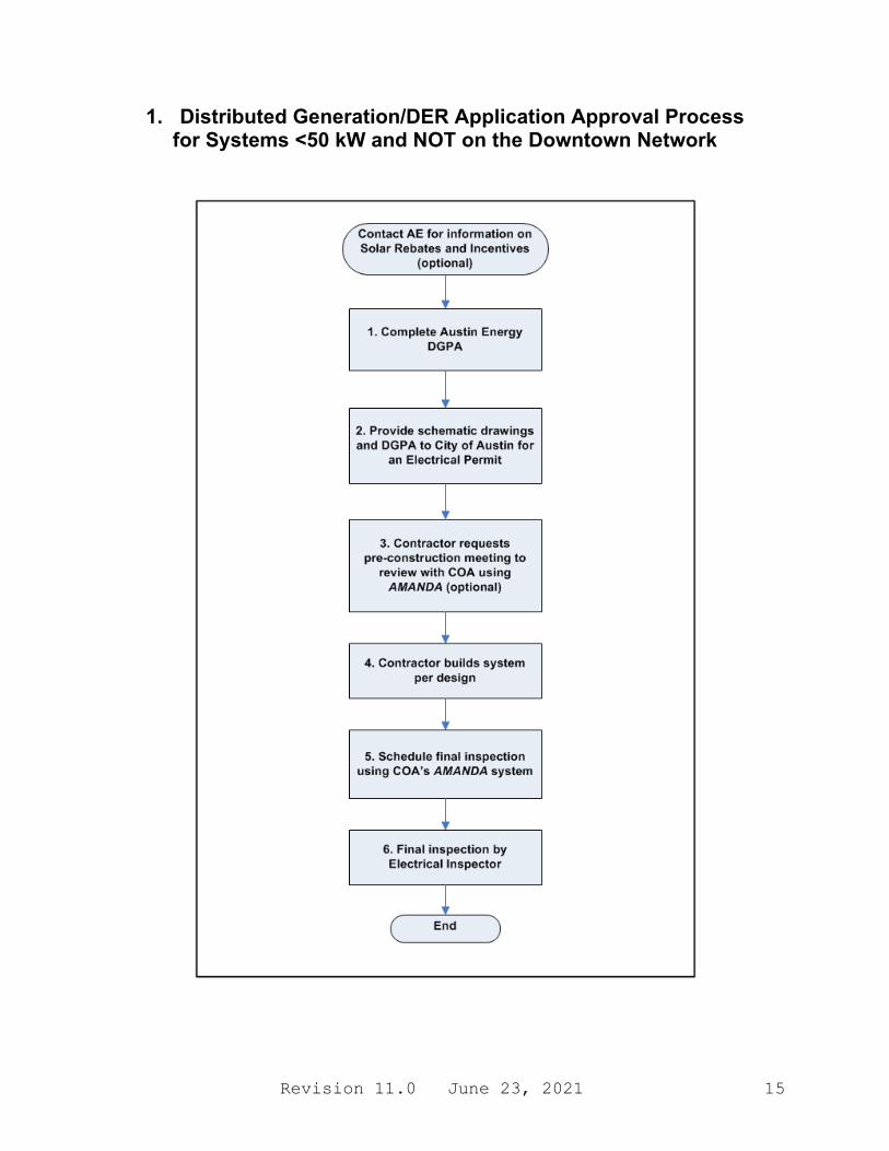
1. Process for Systems Rated <50 kW and NOT on the Downtown Network
Systems less than 50 kW and NOT on the Downtown Network account for approximately 90% of the DG/DER systems installed in the Austin Energy service area, and the process has been streamlined. (See steps a thru f below and the process flow diagram on p.15.) Systems in this category are typically handled through the City of Austin Development Office at One Texas Center. Please call Customer Energy Solutions (CES) at 512-482-5346 if you have questions or need help getting started.
a. The customer is required to fill out a DGPA (Distributed Generation Planning
Application) for any interconnection to the AE system, which can be found on the AE website at:
http://www.austinenergy.com • Select the “Contractors” tab. • Select the “Electric Service Design & Planning" tab. • Note that although the DGPA form is necessary, AE approval is NOT required for
systems less than 50 kW.
b. The customer is then required to obtain an electrical permit from the City of Austin and should provide the following data for obtaining the electrical permit:
i. Physical layout drawing(s) clearly indicating the interconnection equipment shown in Section C.
ii. Electrical one-line diagram, up to, and including, the interface to the AE system. iii. List of major equipment: manufacturer’s name, model number and information
for inverter, overcurrent device, solar modules (if Solar PV). iv. Copy of the inverter manufacturer’s string sizing calculations from their website to
verify that the system is sized appropriately (if Solar PV). v. Completed DGPA.
vi. Energy Storage Systems may approval by Austin Fire Department. Contact [email protected].
a. Energy Storage Systems with a nameplate rating > 20 kWh shall be in accordance with the 2021 International Fire Code. Residential energy storage systems with a nameplate rating > 1 kWh shall be in accordance with 2021 International Residential Code. Check with local Fire Department.
c. The customer is recommended to have a pre-construction review of their plans by contacting
the City Electrical Inspector via AMANDA (see Section F: Definitions). This review is entirely optional. Note that the Installer has to verify NEC compliance of the modified
Revision 11.0 June 23, 2021 14
system, from the point of connection all the way back to the Point of Common Coupling, with the focus on proper size of feeder cables and panel buses.
d. Contractor builds system per plans submitted. Note: Any significant change in the design
must be approved by the City Inspector’s office.
e. After the system is installed, the customer/contractor shall request the final electrical inspection from the COA Electrical Inspection department via AMANDA.
i. The customer shall not start up, test, or operate electrical generating equipment in parallel with the AE electrical system until all inspections have been passed.
f. The customer's system and all equipment associated with the parallel operation of power
production equipment will be inspected to verify that all work has been correctly performed and the system installation complies with all applicable codes and standards.
i. Refer to Appendix C for the current inspection checklist. ii. The customer shall provide, at their expense, their contractor to demonstrate all
protective functions for the inspector.
Revision 11.0 June 23, 2021 15
1. Distributed Generation/DER Application Approval Process for Systems <50 kW and NOT on the Downtown Network

Revision 11.0 June 23, 2021 16
This page intentionally left blank
Revision 11.0 June 23, 2021 17
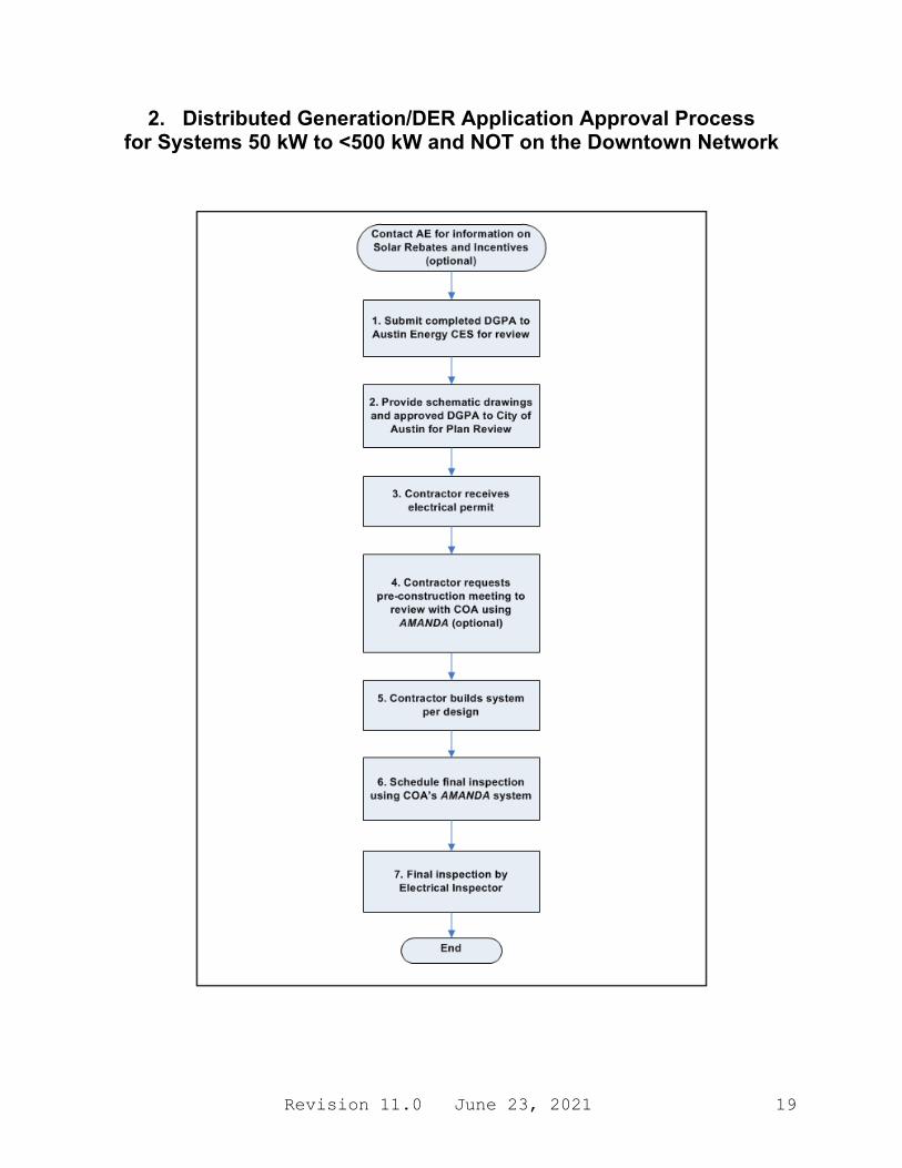
2. Process for Systems Rated 50 kW to <500 kW and NOT on the Downtown Network
Systems from 50 kW to less than 500 kW and NOT on the Downtown Network account for approximately 10% of the DG/DER systems installed in the Austin Energy service area, and the process for obtaining a permit is slightly more complex. (See steps a thru g below and the process flow diagram on p. 19. Also see Section D on p. 38 for any additional requirements.) Systems in this category are typically handled through the City of Austin Development Office at One Texas Center. Please call Customer Energy Solutions (CES) at 512-482-5346 if you have questions or need help getting started. a. The customer is required to submit a completed DGPA (Distributed Generation Planning
Application) to Austin Energy for review for any interconnection to the AE system, which can be found on the AE website at:
http://www.austinenergy.com • Select the “Contractors” tab. • Select the “Electric Service Design & Planning" tab.
b. The DGPA must be accompanied with a full set of drawings and specifications that have
been sealed by a Professional Engineer licensed in the state of Texas. All drawings shall be in electronic files in either pdf or AutoCad .dwg formats. Files larger than 3 MB should be sent in a zipped or compressed format. Upon request, the customer shall submit to AE all technical data or additional information required to evaluate the proposed customer electrical generating facility including, but not limited to, the following as required:
i. Physical layout drawings, including dimensions and interconnection distance.
ii. Schematic drawings up to, and including, the interface to the AE system indicating the interconnection equipment shown in Section C.
iii. Electrical one-line and three-line diagrams, and schematic diagrams identifying continuous and fault current ratings of all equipment to verify compliance to NEC Article 110.10.
iv. System protection details. v. Integration of DG/DER grounding system with AE distribution system per IEEE 1547,
NEC Article 250, and AE Design Criteria Manual. vi. Detailed list of equipment: manufacturer’s name, model number, and rating information.
a) Note: All equipment shall be listed and certified to either UL or NRTL (a Nationally Recognized Testing Laboratory).
vii. Lightning protection and grounding details indicating conformance to NFPA 780 (if required).
viii. Coordination data such as: (for Primary fed customers only – this is not common) a) Functional and logic diagrams.
Revision 11.0 June 23, 2021 18
b) Control and meter diagrams.
c. The customer is also required to go to the Development Services Department of the City of Austin for plan review for obtaining an electrical permit, and the DGPA must be accompanied with a full set of drawings. Upon successful completion of the plan review, the contractor will receive an electrical permit. Note that the Installer has to verify NEC compliance of the modified system, from the point of connection all the way back to the Point of Common Coupling, with the focus on proper size of feeder cables and panel buses.
d. The customer is recommended to have a pre-construction review of their plans by contacting the City Electrical Inspector via AMANDA (see Section F: Definitions). This review is entirely optional.
e. Contractor builds system per plans submitted. Note: Any significant change in the design
must go back through the plan review process.
f. After the system is installed, the customer/contractor shall request the final electrical inspection from the COA Electrical Inspection department via AMANDA. i. The customer shall not start up, test, or operate electrical generating equipment in
parallel with the AE electrical system until all inspections have been passed.
g. The customer's system and all equipment associated with the parallel operation of power production equipment will be inspected to verify that all work has been correctly performed and the system installation complies with all applicable codes and standards. i. Refer to Appendix C for the current inspection checklist.
ii. The customer shall provide, at their expense, their contractor to demonstrate all protective functions for the inspector.
Revision 11.0 June 23, 2021 19
2. Distributed Generation/DER Application Approval Process for Systems 50 kW to <500 kW and NOT on the Downtown Network
Revision 11.0 June 23, 2021 20
This page intentionally left blank

Revision 11.0 June 23, 2021 21
3. Process for Systems Rated 500 kW to less than 10 MW OR on the Downtown Network
Due to the size and complexity of these systems, AE’s System Engineering group is the single point of contact for processing these types of interconnection requests. (See steps a thru g below and the process flow diagram on p. 24. Also see Section D on p. 37 for any additional requirements.) System Engineering will be responsible for coordinating with Complex Metering, Distribution Design, Distribution Planning, Key Accounts, Network Design, Regulatory Analysis, System Operations, and Transmission Planning regarding all technical issues associated with interconnecting to the AE distribution system and can be reached by email at:
a. The customer is required to submit a DGPA (Distributed Generation Planning Application) along with the completed application for any interconnection to the AE system, which can be found on the AE website at:
http://www.austinenergy.com • Select the “Contractors” tab. • Select the “Electric Service Design & Planning" tab.
b. The customer will submit the completed application (Appendix D) to AE System
Engineering containing all required Customer Data. Any installation 500 kW and up, or of any size on the Downtown Network, must be accompanied with a full set of drawings and specifications that have been sealed by a Professional Engineer licensed in the state of Texas. All drawings shall be in electronic files in either pdf or AutoCad .dwg formats. Files larger than 3 MB should be sent in a zipped or compressed format. Upon request, the customer shall submit to AE all technical data or additional information required to evaluate the proposed customer electrical generating facility including, but not limited to, the following as required:
i. Physical layout drawings, including dimensions and interconnection distance.
ii. Conductor sizes and length and technical parameters for circuit impedances. iii. Schematic drawings up to, and including, the interface to the AE system indicating the
interconnection equipment shown in Section C. iv. Electrical main one-line and three-line diagrams and schematic diagrams identifying
continuous and fault current ratings of all equipment to verify compliance to NEC Article 110.10.
v. System protection details. vi. Integration of DG/DER grounding system with AE distribution system per IEEE
1547, NEC Article 250, and AE Design Criteria Manual. vii. Detailed list of equipment: manufacturer’s name, model number, and rating
information.
Revision 11.0 June 23, 2021 22
viii. Manufacturer's test data or certification indicating compliance with national codes concerned with radio noise, harmonic generation, and telephone interference factor.
ix. Lightning protection and grounding details indicating conformance to NFPA 780 (if required).
x. Coordination data such as: a) Functional and logic diagrams. b) Control and meter diagrams. c) Any other data relevant to coordination of the customer system with the AE
system. d) Systems over 500 kW or on the Downtown Network must also have a
written sequence of operation including documented switching procedure(s). e) Synchronizing methods (if any).
xi. Load Data (Downtown Network only): Electrical load analysis based on previous 12 months customer data (where possible) to verify maximum sizing of array for minimum import relay requirements. Refer to Appendix E for an example of how to calculate system size from load.
c. AE System Engineering will review and provide feedback on the proposed facility. An
interconnection study may also be required to determine any mitigation procedures that may be required. Once the final design has been determined, AE System Engineering will issue a letter releasing the DGPA.
d. The customer is also required to go through plan review for obtaining an electrical permit, and the DGPA must be accompanied with a full set of drawings. Upon successful completion of the plan review, the contractor will receive an electrical permit. Note that the Installer has to verify NEC compliance of the modified system, from the point of connection all the way back to the Point of Common Coupling, with the focus on proper size of feeder cables and panel buses.
e. The system shall be installed per the final design in the permit application. Any deviations from the final design (including field changes) shall be communicated to AE/City of Austin for further review. A more detailed commissioning test (if required by AE) shall be mutually agreed on as well that verifies all protective functions per IEEE 1547.
f. After the system is installed, the customer shall request the final electrical inspection from
the COA Electrical Inspection department using the AMANDA (see Section F: Definitions) system.
i. The customer shall not start up, test, or operate electrical generating equipment in parallel with the AE electrical system until final meter installation or written consent of AE has been done.
g. The customer's facility and all equipment associated with the parallel operation of power
production equipment will be inspected to verify that all work has been correctly performed and the system installation complies with all applicable codes and standards.
i. Refer to Appendix C for the current inspection checklist.
Revision 11.0 June 23, 2021 23
ii. The customer shall provide, at their expense, their contractor and any additional equipment (current sources, etc.) required to demonstrate all protective functions for AE and to perform any additional commissioning tests that may be required.
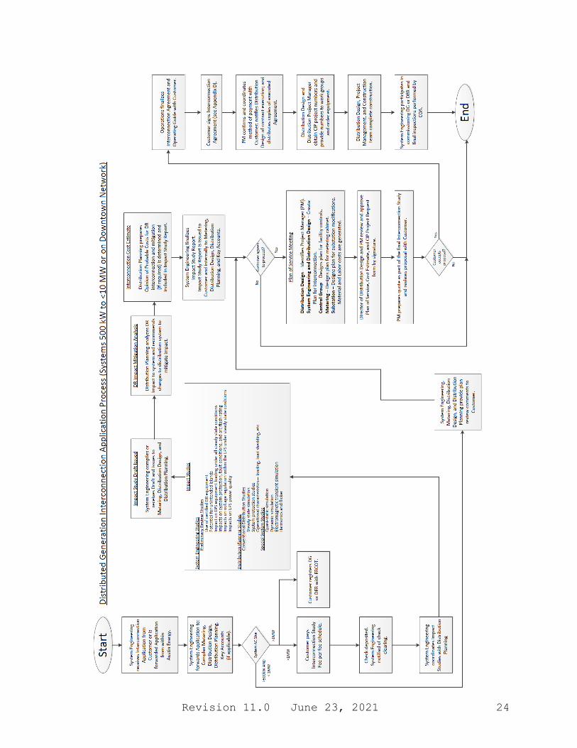
Revision 11.0 June 23, 2021 24
Revision 11.0 June 23, 2021 25
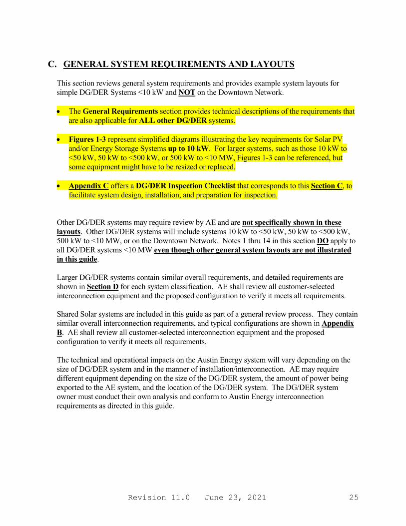
C. GENERAL SYSTEM REQUIREMENTS AND LAYOUTS
This section reviews general system requirements and provides example system layouts for simple DG/DER Systems <10 kW and NOT on the Downtown Network. • The General Requirements section provides technical descriptions of the requirements that
are also applicable for ALL other DG/DER systems.
• Figures 1-3 represent simplified diagrams illustrating the key requirements for Solar PV and/or Energy Storage Systems up to 10 kW. For larger systems, such as those 10 kW to <50 kW, 50 kW to <500 kW, or 500 kW to <10 MW, Figures 1-3 can be referenced, but some equipment might have to be resized or replaced.
• Appendix C offers a DG/DER Inspection Checklist that corresponds to this Section C, to
facilitate system design, installation, and preparation for inspection. Other DG/DER systems may require review by AE and are not specifically shown in these layouts. Other DG/DER systems will include systems 10 kW to <50 kW, 50 kW to <500 kW, 500 kW to <10 MW, or on the Downtown Network. Notes 1 thru 14 in this section DO apply to all DG/DER systems <10 MW even though other general system layouts are not illustrated in this guide.
Larger DG/DER systems contain similar overall requirements, and detailed requirements are shown in Section D for each system classification. AE shall review all customer-selected interconnection equipment and the proposed configuration to verify it meets all requirements.
Shared Solar systems are included in this guide as part of a general review process. They contain similar overall interconnection requirements, and typical configurations are shown in Appendix B. AE shall review all customer-selected interconnection equipment and the proposed configuration to verify it meets all requirements. The technical and operational impacts on the Austin Energy system will vary depending on the size of DG/DER system and in the manner of installation/interconnection. AE may require different equipment depending on the size of the DG/DER system, the amount of power being exported to the AE system, and the location of the DG/DER system. The DG/DER system owner must conduct their own analysis and conform to Austin Energy interconnection requirements as directed in this guide.
Revision 11.0 June 23, 2021 26
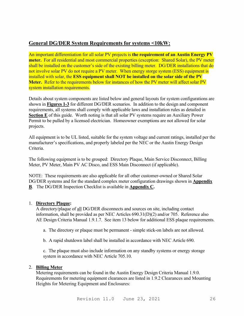
General DG/DER System Requirements for systems <10kW: An important differentiation for all solar PV projects is the requirement of an Austin Energy PV meter. For all residential and most commercial properties (exception: Shared Solar), the PV meter shall be installed on the customer’s side of the existing billing meter. DG/DER installations that do not involve solar PV do not require a PV meter. When energy storge system (ESS) equipment is installed with solar, the ESS equipment shall NOT be installed on the solar side of the PV Meter. Refer to the requirements below for instances of how the PV meter will affect solar PV system installation requirements. Details about system components are listed below and general layouts for system configurations are shown in Figures 1-3 for different DG/DER scenarios. In addition to the design and component requirements, all systems shall comply with applicable laws and installation rules as detailed in Section E of this guide. Worth noting is that all solar PV systems require an Auxiliary Power Permit to be pulled by a licensed electrician. Homeowner exemptions are not allowed for solar projects. All equipment is to be UL listed, suitable for the system voltage and current ratings, installed per the manufacturer’s specifications, and properly labeled per the NEC or the Austin Energy Design Criteria. The following equipment is to be grouped: Directory Plaque, Main Service Disconnect, Billing Meter, PV Meter, Main PV AC Disco, and ESS Main Disconnect (if applicable). NOTE: These requirements are also applicable for all other customer-owned or Shared Solar DG/DER systems and for the standard complex meter configuration drawings shown in Appendix B. The DG/DER Inspection Checklist is available in Appendix C. 1. Directory Plaque:
A directory/plaque of all DG/DER disconnects and sources on site, including contact information, shall be provided as per NEC Articles 690.31(D)(2) and/or 705. Reference also AE Design Criteria Manual 1.9.1.7. See item 13 below for additional ESS plaque requirements.
a. The directory or plaque must be permanent - simple stick-on labels are not allowed.
b. A rapid shutdown label shall be installed in accordance with NEC Article 690.
c. The plaque must also include information on any standby systems or energy storage system in accordance with NEC Article 705.10.
2. Billing Meter
Metering requirements can be found in the Austin Energy Design Criteria Manual 1.9.0. Requirements for metering equipment clearances are listed in 1.9.2 Clearances and Mounting Heights for Metering Equipment and Enclosures:
Revision 11.0 June 23, 2021 27
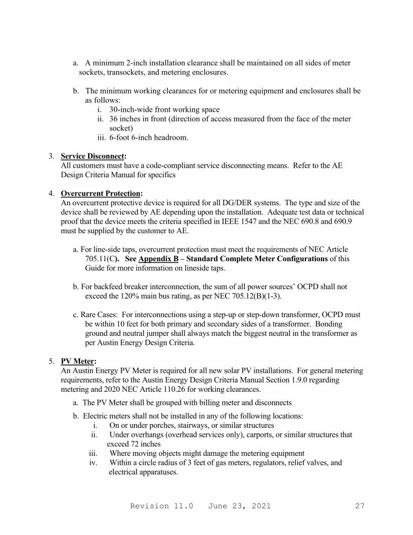
a. A minimum 2-inch installation clearance shall be maintained on all sides of meter
sockets, transockets, and metering enclosures. b. The minimum working clearances for or metering equipment and enclosures shall be
as follows: i. 30-inch-wide front working space ii. 36 inches in front (direction of access measured from the face of the meter
socket) iii. 6-foot 6-inch headroom.
3. Service Disconnect:
All customers must have a code-compliant service disconnecting means. Refer to the AE Design Criteria Manual for specifics
4. Overcurrent Protection:
An overcurrent protective device is required for all DG/DER systems. The type and size of the device shall be reviewed by AE depending upon the installation. Adequate test data or technical proof that the device meets the criteria specified in IEEE 1547 and the NEC 690.8 and 690.9 must be supplied by the customer to AE.
a. For line-side taps, overcurrent protection must meet the requirements of NEC Article 705.11(C). See Appendix B – Standard Complete Meter Configurations of this Guide for more information on lineside taps.
b. For backfeed breaker interconnection, the sum of all power sources’ OCPD shall not
exceed the 120% main bus rating, as per NEC 705.12(B)(1-3). c. Rare Cases: For interconnections using a step-up or step-down transformer, OCPD must
be within 10 feet for both primary and secondary sides of a transformer. Bonding ground and neutral jumper shall always match the biggest neutral in the transformer as per Austin Energy Design Criteria.
5. PV Meter:
An Austin Energy PV Meter is required for all new solar PV installations. For general metering requirements, refer to the Austin Energy Design Criteria Manual Section 1.9.0 regarding metering and 2020 NEC Article 110.26 for working clearances.
a. The PV Meter shall be grouped with billing meter and disconnects b. Electric meters shall not be installed in any of the following locations:
i. On or under porches, stairways, or similar structures ii. Under overhangs (overhead services only), carports, or similar structures that
exceed 72 inches iii. Where moving objects might damage the metering equipment iv. Within a circle radius of 3 feet of gas meters, regulators, relief valves, and
electrical apparatuses.
Revision 11.0 June 23, 2021 28
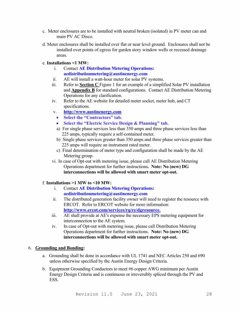
c. Meter enclosures are to be installed with neutral broken (isolated) in PV meter can and main PV AC Disco.
d. Meter enclosures shall be installed over flat or near level ground. Enclosures shall not be installed over points of egress for garden story window wells or recessed drainage areas.
e. Installations <1 MW: i. Contact AE Distribution Metering Operations:
[email protected] ii. AE will install a watt-hour meter for solar PV systems.
iii. Refer to Section C Figure 1 for an example of a simplified Solar PV installation and Appendix B for standard configurations. Contact AE Distribution Metering Operations for any clarification.
iv. Refer to the AE website for detailed meter socket, meter hub, and CT specifications.
v. http://www.austinenergy.com • Select the “Contractors” tab. • Select the “Electric Service Design & Planning" tab. a) For single phase services less than 350 amps and three phase services less than
225 amps, typically require a self-contained meter. b) Single phase services greater than 350 amps and three phase services greater than
225 amps will require an instrument rated meter. c) Final determination of meter type and configuration shall be made by the AE
Metering group. vi. In case of Opt-out with metering issue, please call AE Distribution Metering
Operations department for further instructions. Note: No (new) DG interconnections will be allowed with smart meter opt-out.
f. Installations >1 MW to <10 MW:
i. Contact AE Distribution Metering Operations: [email protected]
ii. The distributed generation facility owner will need to register the resource with ERCOT. Refer to ERCOT website for more information: http://www.ercot.com/services/rq/re/dgresource.
iii. AE shall provide at AE's expense the necessary EPS metering equipment for interconnection to the AE system.
iv. In case of Opt-out with metering issue, please call Distribution Metering Operations department for further instructions. Note: No (new) DG interconnections will be allowed with smart meter opt-out.
6. Grounding and Bonding:
a. Grounding shall be done in accordance with UL 1741 and NEC Articles 250 and 690 unless otherwise specified by the Austin Energy Design Criteria.
b. Equipment Grounding Conductors to meet #6 copper AWG minimum per Austin Energy Design Criteria and is continuous or irreversibly spliced through the PV and ESS.
Revision 11.0 June 23, 2021 29
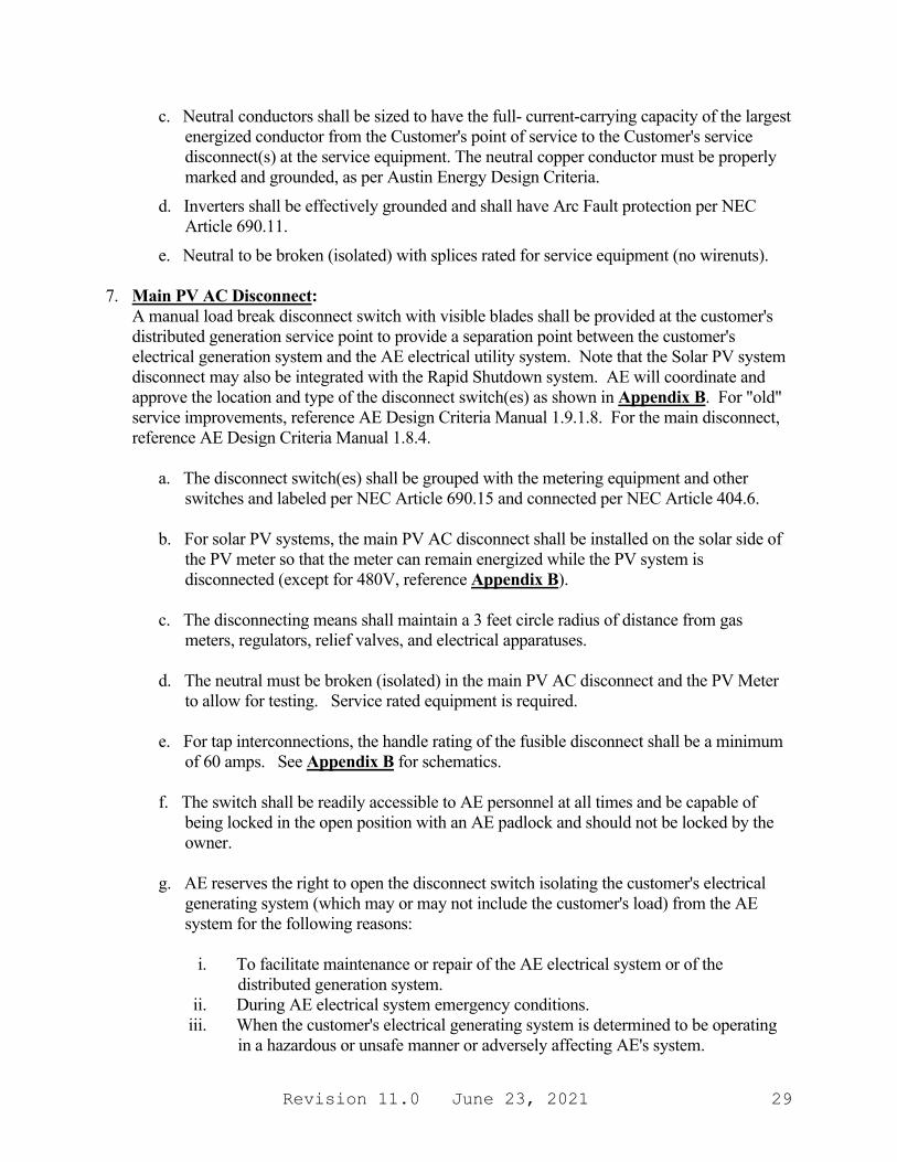
c. Neutral conductors shall be sized to have the full- current-carrying capacity of the largest energized conductor from the Customer's point of service to the Customer's service disconnect(s) at the service equipment. The neutral copper conductor must be properly marked and grounded, as per Austin Energy Design Criteria.
d. Inverters shall be effectively grounded and shall have Arc Fault protection per NEC Article 690.11.
e. Neutral to be broken (isolated) with splices rated for service equipment (no wirenuts). 7. Main PV AC Disconnect:
A manual load break disconnect switch with visible blades shall be provided at the customer's distributed generation service point to provide a separation point between the customer's electrical generation system and the AE electrical utility system. Note that the Solar PV system disconnect may also be integrated with the Rapid Shutdown system. AE will coordinate and approve the location and type of the disconnect switch(es) as shown in Appendix B. For "old" service improvements, reference AE Design Criteria Manual 1.9.1.8. For the main disconnect, reference AE Design Criteria Manual 1.8.4.
a. The disconnect switch(es) shall be grouped with the metering equipment and other switches and labeled per NEC Article 690.15 and connected per NEC Article 404.6.
b. For solar PV systems, the main PV AC disconnect shall be installed on the solar side of
the PV meter so that the meter can remain energized while the PV system is disconnected (except for 480V, reference Appendix B).
c. The disconnecting means shall maintain a 3 feet circle radius of distance from gas
meters, regulators, relief valves, and electrical apparatuses. d. The neutral must be broken (isolated) in the main PV AC disconnect and the PV Meter
to allow for testing. Service rated equipment is required. e. For tap interconnections, the handle rating of the fusible disconnect shall be a minimum
of 60 amps. See Appendix B for schematics. f. The switch shall be readily accessible to AE personnel at all times and be capable of
being locked in the open position with an AE padlock and should not be locked by the owner.
g. AE reserves the right to open the disconnect switch isolating the customer's electrical
generating system (which may or may not include the customer's load) from the AE system for the following reasons:
i. To facilitate maintenance or repair of the AE electrical system or of the
distributed generation system. ii. During AE electrical system emergency conditions.
iii. When the customer's electrical generating system is determined to be operating in a hazardous or unsafe manner or adversely affecting AE's system.
Revision 11.0 June 23, 2021 30
iv. Failure of the customer to comply with applicable codes, regulations, and standards in effect at that time.
v. Failure to abide by any contractual arrangement or operating agreement with AE. 8. Surge Protection Device (Solar PV only):
The device (Type 1 or 2) shall be appropriately sized for the service entrance per NEC 230.67. Note on UL 1449 3rd Edition Type 1 and Type 2 Surge Protection: Type 1 Surge Protective Device (SPD) - Permanently connected Type 1 SPD's are intended for installation between the secondary of the service transformer and the line side of the service equipment overcurrent device. Type 2 Surge Protective Device -Permanently connected Type 2 SPD's are intended for installation on the load side of the service equipment overcurrent device.
9. Inverters (for inverter-based systems):
a. Solar PV inverters shall be certified to UL 1699B, UL 1741, and IEEE 1547 and must be on the approved list published by the California Energy Commission (CEC) on its website http://www.gosolarcalifornia.org.
b. Non-solar PV inverters may not be installed on the Solar PV side of the PV Meter.
These inverters must meet the requirements of IEEE 1547 and be certified to UL 1741, and UL 2200, if applicable, and may not be self-commutating while paralleled with the AE system.
i. Inverters shall be set per the default settings as defined in IEEE 1547-2018 (or 300 seconds).
ii. Inverters in areas with high levels of DG/DER penetration may require alternate settings.
c. Inverters used with energy storage systems shall be certified by the Energy Storage
System battery manufacturer for use with their system. Inverters shall be listed to UL 1741 or UL 9540 and shall be listed for utility interaction.
d. Inverters used to provide backup power (such as for ESS) shall include a transfer switch
to disconnect from the AE system while operating in island mode using self-commutation as per NEC 2020 Article 705.40.
e. Three phase systems must either use a three-phase inverter or single-phase inverters
arranged in a wye configuration. Single phase inverters may not be connected in a delta configuration due to grounding concerns.
9.1 Protective Devices and Functions:
All DG/DER installations shall have protective devices that provide an automatic method of disconnecting its generation equipment from the AE system along with electronic programmable relays to meet the requirements of IEEE 1547, Section 4 - "General Interconnection Technical Specifications and Performance Requirements". The automatic disconnecting device may be of the manual or automatic reclose type and shall not be capable of reclosing until the AE System voltage and frequency return to normal range and the system is

Revision 11.0 June 23, 2021 31
stabilized for the duration specified in (f) below. Note that inverters certified to UL 1741 provide many of these functions.
a. Voltage and Flicker: The customer equipment shall provide under/overvoltage trip capability. AE shall endeavor to maintain the voltages on the AE system but shall not be responsible for factors or circumstances beyond its control. If the customer's electrical generation equipment has automatic voltage control capability, it shall be operated in the manual mode with power factor control consistent with the power factor requirement set out below and in IEEE 1547.
i. The customer owned equipment will not cause AE system voltage to go outside of the limits set by ANSI C84.1.
ii. In accordance with IEEE 519, the flicker shall not exceed 3.0% voltage change, measured at the point of common coupling. If high or low voltage complaints or flicker complaints result from the operation of the customer's electrical generation, the customer's generating system shall be disconnected until the problem is resolved.
b. Frequency: The customer equipment shall provide under/over-frequency trip capability.
AE will endeavor to maintain a 60-hertz nominal frequency on the AE system. If the customer's electrical generation equipment has speed or frequency control, it shall be operated in the manual droop mode.
c. Harmonics: The customer's electrical generation system shall not cause voltage
harmonic content or total harmonic distortion (THD) in excess of the limits of IEEE 519 and IEEE 1547 when measured at the point of common coupling with the AE system.
d. Fault and Loss of Source: In accordance with IEEE 1547, in the event of a fault on the
customer's system or a fault or loss of source on the AE system, the customer shall provide an automatic method of disconnecting its generation equipment from the AE system within 10 cycles should the voltage on one or more phases fall below 50% of nominal voltage on the AE system serving the customer premises at the point of common coupling.
i. In the event of an outage, the DG/DER system shall contain anti-islanding protection to de-energize the system and prevent inadvertent backfeed during an outage into AE’s electrical system.
ii. Installations over 2 MW shall provide for transfer trip of the DG/DER facility. e. Power Factor: The customer's electrical generation system shall be designed, operated,
and controlled at all times to provide reactive power requirements at the point of interconnection per IEEE 1547, but in no case exceeding from 0.95 lagging to 0.95 leading power factor unless approved in writing by AE. Refer to Section D for systems over 50 kW.
f. Reconnection to AE Service: After any disturbance resulting in a service interruption or
feeder breaker actuation, no Distributed Generation/DER source may reconnect until the AE System voltage and frequency return to normal range and the system is stabilized for
Revision 11.0 June 23, 2021 32
a period of 300 seconds, or as approved in writing by AE. This disconnect timing ensures that the generator is disconnected from the AE System prior to automatic re-close of feeder breakers.
g. Relay Settings (if applicable): The settings for all distribution interconnections shall be
approved by System Engineering in conjunction with IEEE 1547 and AE Transmission and Substation Engineering and Construction as necessary.
To enhance system reliability and safety and with AE’s approval, the customer may
employ a modified relay scheme with delayed frequency or voltage tripping using communications equipment between the customer and AE.
10. Additional Disconnect(s):
The location of all disconnects shall be clearly indicated on the informational directory/plaque (see item 1 above).
a. Solar PV: Manual and/or fusible disconnects shall be required for system maintenance. No toggle switches are allowed. Check with AHJ to determine if additional rooftop disconnects will be required to meet Rapid Shutdown or maintenance requirements. Email [email protected].
i. For 480 V systems an additional disconnecting means is required between the PV meter and the interconnection. See diagrams B-5 and B-6 in Appendix B.
b. Energy Storage Systems (ESS): At least one lockable, visible blade DC disconnect is
required for first responders on external DC conductors between the battery and the inverter (not required for self-contained systems). Additional disconnects may be required in accordance with 2020 NEC 706.15. ESS disconnects are required to be installed within 5 ft of the main panel, and also readily accessible and within sight of the ESS. Check with the local Fire Department for additional requirements. Additional labelling required for ESS Main Disconnect and Main Service Panel: WARNING ENERGY STORAGE SYSTEM ON SITE: ESS BREAKER IN GENERATION PANEL AND MAIN BREAKER IN MAIN SERVICE PANEL MUST BE OFF FOR WHOLE HOME ELECTRIC SHUTOFF.
c. Inverter-Integrated Energy Storage Systems (ESS): A lockable, visible blade AC
disconnect is required for first responders on self-contained systems when used in a backup application. The disconnect shall be located within 5 feet and in sight of the battery, and before the backup panel. Additional disconnects may be required in accordance with 2020 NEC 706.15. ESS disconnects are required to be installed within 5 ft of the main panel, and also readily accessible and within sight of the ESS. Check with the local Fire Department for additional requirements. Additional labelling required for ESS Main Disconnect and Main Service Panel: WARNING ENERGY STORAGE SYSTEM ON SITE: ESS BREAKER IN GENERATION PANEL AND MAIN BREAKER IN MAIN SERVICE PANEL MUST BE OFF FOR WHOLE HOME ELECTRIC SHUTOFF.
Revision 11.0 June 23, 2021 33
c. Isolation Switch: An isolation switch shall be required to automatically disconnect AE from any distributed generation sources upon loss of primary power and shall not be reconnected until the primary source is restored in accordance with NEC 705.40.
11. AC & DC Wiring:
a. Service conductors shall be color coded as directed in the Austin Energy Design Criteria,
Section 1.3.7. b. All wiring shall be copper only, not aluminum. c. For all interconnections at non-dedicated subpanels, the conductors supplying the
subpanel must be sized for the ampacity of the subpanel load and the interconnected power source
12. Raceways
a. Raceways containing PV output conductors must be dedicated and labeled as required
by NEC 690. PV communication wires must be run separately. This is an enhancement beyond NEC 690.31 requirements.
b. No more than 360 degrees of cumulative bends are permitted in any conduit run. c. Conductors (both AC and DC) run internal to attic spaces are required to be in metal
conduit. d. Any threaded conduit shall have threaded fittings, non-threaded fittings are not suitable.
13. Energy Storage System (ESS):
a. All Energy Storage System equipment shall be certified to UL 1973, and installation
shall comply with manufacturer’s instructions. All ESS that contain electrochemical cells shall be listed in accordance with UL 9540. Lithium Ion systems shall be certified to UL 1642. Lead-Acid systems shall be certified to UL 1989.
b. A directory plaque shall be installed by the ESS equipment.
c. Energy Storage System plans shall be sealed by a Professional Engineer licensed in the state of Texas.
d. When installed in parallel with other DG, such as a solar PV system: an ESS may not simultaneously discharge to the AE distribution system with an adjoining solar PV system unless the capacity of the transformer serving the customer has been reviewed by AE to ensure safe operation.
Revision 11.0 June 23, 2021 34
e. During inspection, batteries must exhibit ability to hold charge without damage. PV system may be operational at the time of inspection and be able to demonstrate full functionality.
f. A disconnecting means shall be provided for all ungrounded conductors derived form an ESS. The disconnecting means shall be readily accessible and located within sight of the ESS. A disconnecting means also shall be installed within 5 ft of the main service. See Section 10, Additional Disconnects.
g. ESS cannot be installed on the solar side of the solar PV meter. For this reason, no DC-Coupled solar PV and battery systems shall be permitted.
h. Within the City of Austin, Fire department approval shall be required for ESS installations exceeding 20 kWh. Contact [email protected] or check with your local fire department.
14. Solar PV Array:
a. Any installation methods that are not flush to the roof shall require a building permit with plans sealed by a Professional Engineer licensed in the state of Texas.
b. Check with your local fire department to ensure solar panel installation meets fire code requirements. The IFC along with many other codes can be found at: www.codes.iccsafe.org/codes/texas
15. Rapid Shutdown Feature (Solar PV only):
All installations submitted for approval shall incorporate a rapid shutdown feature if required by the AHJ per Article 690.12 of the NEC: voltage below 30 volts within 30 seconds of rapid shut down initiation.
Revision 11.0 June 23, 2021 35
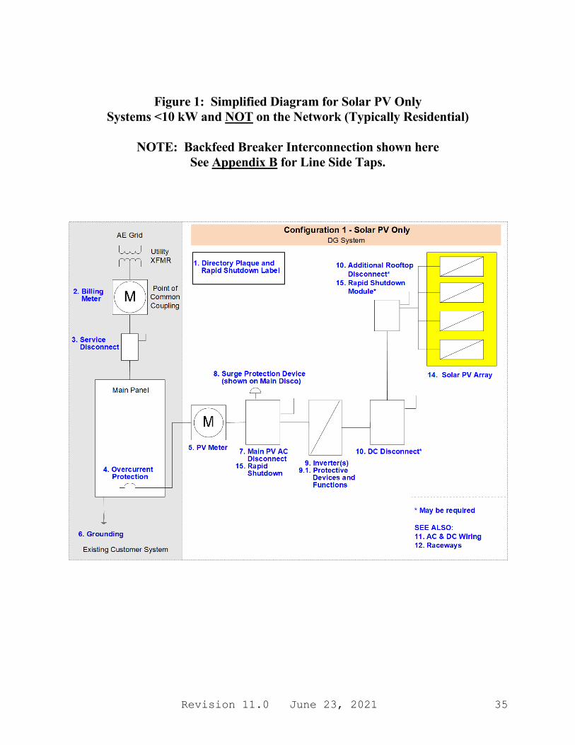
Figure 1: Simplified Diagram for Solar PV Only Systems <10 kW and NOT on the Network (Typically Residential)
NOTE: Backfeed Breaker Interconnection shown here
See Appendix B for Line Side Taps.
Revision 11.0 June 23, 2021 36
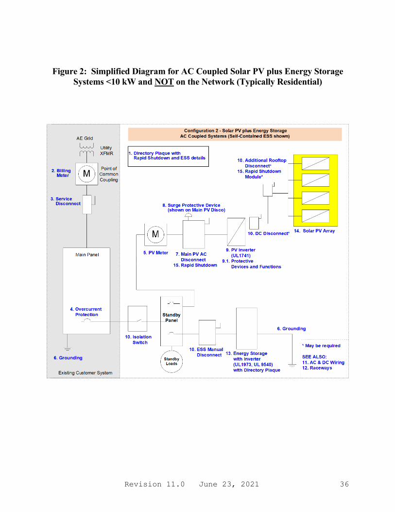
Figure 2: Simplified Diagram for AC Coupled Solar PV plus Energy Storage Systems <10 kW and NOT on the Network (Typically Residential)
Revision 11.0 June 23, 2021 37
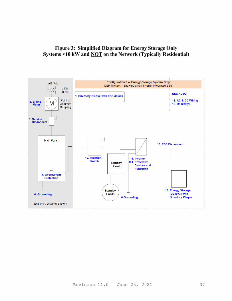
Figure 3: Simplified Diagram for Energy Storage Only Systems <10 kW and NOT on the Network (Typically Residential)

Revision 11.0 June 23, 2021 38
D. DETAILED REQUIREMENTS FOR PARALLEL SYSTEMS
1. Additional Technical Requirements by System Classification
a. Systems (not on the Downtown Network) less than 50 kW (typically residential): i. No additional requirements.
b. Systems (not on the Downtown Network) rated at least 50 kW to less than 1 MW
must also have: i. An automatic sync-check relay (if generator is synchronous or self-commutated) or
open transition transfer switch. ii. If the facility is exporting power, the power direction protective function may be used
to block or delay the under frequency trip with the agreement of AE (not common). iii. The system must have the ability to provide power factor support from 0.9 lagging to
0.9 leading. Exact settings will be determined with AE. iv. Refer to simplified diagrams in Section C, Figures 1 thru 5, for "typical" layouts.
Figures 1 thru 5 represent simplified diagrams illustrating the key requirements for Solar PV and/or Energy Storage Systems. They are showing "typical" 10 kW systems only and are not all-inclusive of other systems (such as those <50 kW, 50 kW to less than 500 kW, or 500 kW to less than 10 MW).
v. Other DG/DER systems may require review by AE and are not specifically shown in these layouts. Other DG/DER systems will include systems 10 kW to <50 kW, 50 kW to <500 kW, 500 kW to less than 10 MW, or on the Downtown Network. Notes 1 thru 14 in Section C DO apply to all DG/DER systems <10 MW even though other (additional) general system layouts are not illustrated in this guide.
c. Systems (not on the Downtown Network) rated >1 MW to less than 10 MW must
have: i. If the facility is capable of exporting to the AE system, there shall be a redundant
circuit breaker interfaced to the AE relay system (required for 2 MW and up for DG/DER inverter based systems and for 1 MW and up for synchronous or induction motor systems).
ii. EPS metering is required for systems 1 MW and up. Refer to Metering, Section C.5, for additional requirements.
iii. Utility grade relays approved by AE and compatible with AE relay communication. The relay shall be compatible with Mirrored Bits protocol. The relay shall provide the following functions at a minimum:
a) An undervoltage/overvoltage trip with sensing/readout by phase. b) An under/over frequency trip with sensing/readout by phase. c) An automatic synchronism check relay (for facilities with stand-alone
capability). d) Telemetry/transfer trip to be done in accordance with IEEE 1547 and PUC
Substantive Rule §25. 212 (transfer trip for DG/DER inverter based systems rated more than 2 MW but less than 10 MW). For 1 MW and up synchronous or induction motor systems, install transfer trip function per AE requirements.
Revision 11.0 June 23, 2021 39
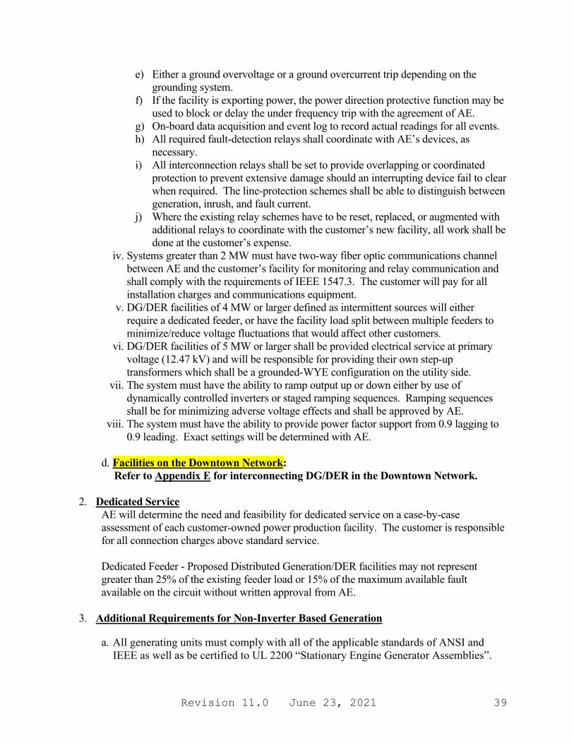
e) Either a ground overvoltage or a ground overcurrent trip depending on the grounding system.
f) If the facility is exporting power, the power direction protective function may be used to block or delay the under frequency trip with the agreement of AE.
g) On-board data acquisition and event log to record actual readings for all events. h) All required fault-detection relays shall coordinate with AE’s devices, as
necessary. i) All interconnection relays shall be set to provide overlapping or coordinated
protection to prevent extensive damage should an interrupting device fail to clear when required. The line-protection schemes shall be able to distinguish between generation, inrush, and fault current.
j) Where the existing relay schemes have to be reset, replaced, or augmented with additional relays to coordinate with the customer’s new facility, all work shall be done at the customer’s expense.
iv. Systems greater than 2 MW must have two-way fiber optic communications channel between AE and the customer’s facility for monitoring and relay communication and shall comply with the requirements of IEEE 1547.3. The customer will pay for all installation charges and communications equipment.
v. DG/DER facilities of 4 MW or larger defined as intermittent sources will either require a dedicated feeder, or have the facility load split between multiple feeders to minimize/reduce voltage fluctuations that would affect other customers.
vi. DG/DER facilities of 5 MW or larger shall be provided electrical service at primary voltage (12.47 kV) and will be responsible for providing their own step-up transformers which shall be a grounded-WYE configuration on the utility side.
vii. The system must have the ability to ramp output up or down either by use of dynamically controlled inverters or staged ramping sequences. Ramping sequences shall be for minimizing adverse voltage effects and shall be approved by AE.
viii. The system must have the ability to provide power factor support from 0.9 lagging to 0.9 leading. Exact settings will be determined with AE.
d. Facilities on the Downtown Network:
Refer to Appendix E for interconnecting DG/DER in the Downtown Network.
2. Dedicated Service AE will determine the need and feasibility for dedicated service on a case-by-case assessment of each customer-owned power production facility. The customer is responsible for all connection charges above standard service. Dedicated Feeder - Proposed Distributed Generation/DER facilities may not represent greater than 25% of the existing feeder load or 15% of the maximum available fault available on the circuit without written approval from AE.
3. Additional Requirements for Non-Inverter Based Generation
a. All generating units must comply with all of the applicable standards of ANSI and IEEE as well as be certified to UL 2200 “Stationary Engine Generator Assemblies”.
Revision 11.0 June 23, 2021 40
b. The customer should contact Austin Energy to determine the phase rotation at their proposed site.
c. Fault current of the system must be recalculated to include the proposed generation, and all equipment must be rated to handle the increased fault current.
d. Machine rating will be determined from faceplate rating of the generator at 100% power factor.
e. Synchronous machines i. The distributed generation facility’s circuit breakers shall be three-phase devices
with electronic control. ii. The customer is solely responsible for proper synchronization of its generator with
the AE system. iii. The generator’s excitation system shall conform to the field voltage versus time
criteria specified in the most recent version of IEEE Standard C50.13. iv. For generating systems greater than 2 (two) megawatts (MW) the customer shall
maintain the automatic voltage regulator (AVR) of each generating unit in service and operable at all times. AE shall be notified if the AVR is removed from service for maintenance or repair.
f. Induction machines i. The induction machines used for generation may be connected and brought up to
synchronous speed (as an induction motor) if it can be demonstrated that the initial voltage drop at the point of interconnection is within the flicker limits specified in this document.
ii. Induction generators shall have static capacitors that provide at least 95% of the magnetizing current requirements of the induction generator field. AE may, in the interest of safety, authorize the omission of capacitors. However, where capacitors are used for power factor correction, additional protective devices may be required to guard against self-excitation of the customer's generator field.
4. Additional Requirements for Electric Energy Storage Systems
a. All Energy Storage Systems (ESS) shall be installed per manufacturer’s instructions.
b. A second AC disconnect means shall be installed in proximity to the Energy Storage System if the AE required disconnect is not within sight.
c. A disconnecting means shall be provided for all ungrounded conductors derived from an ESS. The disconnecting means shall be readily accessible and located within sight of the ESS.
d. Energy Storage Systems installed in parallel with other DG, such as Solar PV(as shown in Figure 2, page 36), may not both simultaneously discharge to the AE distribution system, unless the capacity of the transformer serving the customer has been reviewed by AE to ensure safe operation.
Revision 11.0 June 23, 2021 41
5. Other Protective Devices The foregoing provides a statement of the minimum requirements for parallel operation on the AE system. In addition, AE will have the right to specify certain protective devices including relays and circuit breakers that must be installed at the customer's expense to operate in parallel with AE's system, to protect the safety of its employees and equipment, maintain the reliability of the system, or improve the accuracy of its metering equipment.
6. Technical Exceptions
a. AE will review and consider exceptions that customers may have to the "Requirements for Parallel Systems" provided, however, that legal requirements such as compliance with fire safety, electrical, or construction codes may not be waived unless such law, code, or ordinance provides for waiver or approval of alternate requirements and then only under the conditions set out therein for the grant of such waiver or written approval of alternate requirements.
b. Customers desiring to present exceptions for consideration should submit in writing a
completed description of the nature of each such exception to AE. c. Customers submitting exceptions should also include recommendations for an alternative
approach to this particular requirement.
Revision 11.0 June 23, 2021 42
E. COMPLIANCE WITH APPLICABLE LAWS AND INSTALLATION RULES
1. Compliance with Laws: All customer-owned power production facilities located in the AE
service area shall comply with the latest version of the Austin Electrical Utility Service regulations, City of Austin Electrical Code (§25-12-111), ERCOT Distributed Generation Requirements, NFPA 70 (National Electrical Code), and NESC (National Electrical Safety Code), as well as the most current version of all other applicable federal, state, or local laws or ordinances as of date of installation. Refer to Section G for a listing of additional codes and standards. AE customers in areas outside of the City of Austin may be required to have an additional permit depending on any local authority having jurisdiction (AHJ).
2. Compliance with Installation Rules: All customer-owned power production facilities shall
also comply with the Installation Rules and Standards for Electric Service established for the AE service area. All equipment rated for use at 1000V or below shall be UL listed and shall comply with NEC Article 490. a. Note that per City and State Law, Solar PV systems may only be installed by a
licensed contractor. Homeowner exemptions do not apply for working on electrical services.
3. Applicability for Emergency or Standby Systems: Emergency and/or standby systems as
defined in Articles 700 through 702 of the NEC not in parallel with the AE electrical distribution system, other than brief transition switching periods, are not required to follow this interconnection procedure. However, if the design of the system involves parallel operation with the AE distribution system for periods typically longer than 15 seconds, then the customer is required to follow the procedure outlined in this guide. Note: Any closed transition switching requires synchronizing controls.
4. Interconnection Studies: Detailed interconnection studies may be required if the generation is connected to AE’s distribution system and AE determines it to be necessary for safety and reliability purposes:
a. Facilities rated <500 kW (not on the network)
i. Interconnection study typically not required for equipment pre-certified to UL 1741.
b. Facilities rated 500 kW to <1 MW i. Interconnection study typically not required for equipment pre-certified to UL 1741.
ii. If an interconnection study is desired, AE to bear all costs for studies performed. c. Facilities rated >1 MW but less than 10 MW, or on the Downtown Network
i. Interconnection study typically required at customer’s expense. ii. Austin Energy shall determine the cost and timeline for performing a detailed
interconnection study.
Revision 11.0 June 23, 2021 43
5. Installation Safety: Due to the arc flash hazards present in larger commercial systems, all work on the customer electrical system shall be performed under the direct supervision of a Master Electrician. a. All energized meter sockets shall be covered with a UL listed plastic meter cover blank-off
plate until the meter has been installed to prevent inadvertent electrical contact.
6. Inspection: All customer-owned power production facilities shall be inspected for compliance with minimum safety code requirements and installation rules by a licensed electrical inspector. Isolated systems will also be inspected to ensure that the customer's load and power production equipment are not connected to an electrical circuit in common with the AE system. Inspection approval shall mean only that as of the date of the inspection, the customer's system met minimum code requirements at the time of such inspection and shall not be construed as endorsement, approval, or recommendation of a particular system design for the customer's needs nor a representation that the facility continues to comply with such codes following the inspection.
7. Enforcement: AE reserves the right to discontinue electric service to customers who have
interconnected without AE authorization, fail or refuse to comply with minimum requirements or applicable law, or who, as determined by AE, are operating their power production equipment in a hazardous or unsafe manner. AE may also pursue such other and further rights or remedies as are available to enforce these requirements.
8. Operating Safety: Adequate protection and documented operational procedures must be
jointly developed and followed by the customer and AE for each customer power production facility operating in parallel with the AE system. These operating procedures must be approved by both the customer and AE. The customer shall be required to furnish, install, operate, and maintain in good order and repair and be solely responsible for, without cost to AE, all facilities required for the safe operation of a customer generation system in parallel with the AE system.
9. Maintenance of Protective Equipment: All interconnection equipment on the customer's facility shall be installed and maintained by the customer at their sole expense and in accordance with minimum guidelines established by AE. a. The customer shall provide a maintenance schedule and perform maintenance of
protective equipment at their sole expense at least every two (2) years, or as mandated by current standards, equipment manufacturer recommendations, or as required by AE to provide a safe, reliable system while operating in parallel with the AE system. Circuit breakers must be trip-tested by the customer at least once each year.
b. A periodic test report log shall be maintained. Testing shall include, but is not limited
to, for example, the tripping of the circuit breakers by the protective relays. The customer shall provide appropriate access to all facilities for the purpose of such inspections. AE reserves the right to periodically re-inspect the system with prior notification to the customer.
Revision 11.0 June 23, 2021 44
c. Maintenance records for parallel systems must be provided to AE upon request.
10. Self-Protection: The minimum protection requirements are designed and intended to protect the Austin Energy electrical distribution system only. The customer shall provide, at their sole expense, all devices necessary to protect the customer's electrical generating system by conditions that may occur on the AE system resulting in interruptions and restorations of electrical service. The equipment so installed must protect the customer's electric generating system from overvoltage, undervoltage, overload, short circuits, including ground fault conditions, open circuits, phase imbalance and reversal, over and under frequency conditions, and other injurious electrical conditions that may arise during the operation of the AE system.
11. Capital Cost Responsibility: The customer is required to bear all initial and subsequent
costs associated with the change-out, upgrading, or addition of protective devices, transformers, poles, line, services, meters, switches, and associated equipment and devices beyond that which would be required to provide normal service to the customer if no generation was involved. The customer shall be invoiced for all material and labor that are required in excess of those covered by other applicable installation charges or fees (see appropriate schedules). Upon written request, AE shall supply the customer a cost estimate prior to any work being done.
12. Liability: The customer assumes all responsibility for damage or loss that may occur from
improper coordination and synchronization of its generator with the AE system. a. The customer shall provide proof of insurance of at least $500,000 for systems over 500
kW and at least $1M for systems over 1 MW. b. The customer shall be responsible for coordination and synchronization of the customer's
electrical generating system with all aspects of AE's electrical system.
13. Confidentiality: Due to the nature of the rapidly evolving regulations for DG/DER, non-specific information might be shared among working groups to better understand and optimize the process for interconnection. Detailed or specific information provided, such as customer identification, one-line or site diagrams, or specific component information, shall not be shared without customer approval.
14. Third Party Leases: Austin Energy is the exclusive provider of electric service within its service territory. State law prohibits other owners of electric equipment from furnishing electricity for compensation. Therefore, leases related to solar generation must be equipment leases for flat payments and may not be based on volumetric charges or multipliers for the kWh output of the photovoltaic equipment, nor may leases be based on the customer’s consumption from the equipment. As such, a customer may generate electricity to meet its own needs but cannot buy electricity from anyone else. A customer may lease the equipment on a cost basis but may not have lease payments based on the energy produced, which would be construed as the sale of electricity. It is up to each customer lessee and solar equipment lessor to ensure that a lease does not violate state law.

Revision 11.0 June 23, 2021 45
F. DEFINITIONS
1. AE System: The Electric Utility System of Austin Energy (AE). A detailed map of the service area is available on the Austin Energy Storm Center Website: https://my.austinenergy.com/outages/
2. AMANDA: AMANDA is "Application Management & Data Automation", a software
application system for development review, permitting, and inspection. AMANDA™ is a Case Management & Process Automation Platform that empowers government agencies with enterprise permitting solutions that automate all the steps involved in permits, including application, review, approval, issuance and inspections.
3. Anti-islanding: Detection circuitry required for DG systems that sense when a power
outage has occurred on the utility lines and shuts itself off so there is no possibility of backfeeding into the utility system.
4. Backfeed: A situation whereby the normal power flow is reversed and current flows from the customer system into the AE distribution system.
5. Customer: Refers to both co-generators and small power producers within the AE service
area who use conventional fossil fuels or alternative sources such as solar, wind, or biomass to produce power. The customer must have legal ownership rights of the proposed distributed generation facility and property.
6. Dedicated Service: A feeder or transformer, or both, in the AE Distribution system that only
serves a single customer. 7. DGPA: Distributed Generation Planning Application form(s) which are required to be
filled out for any Distributed Generation or DER interconnection to Austin Energy: http://www.austinenergy.com
• Select the “Contractors” tab. • Select the “Electric Service Design & Planning" tab.
8. Distributed Energy Resources (DER): Systems that are small-scale power generation or
storage technologies (typically in the range of 1 kW to 10,000 kW) used to provide an alternative to or an enhancement of the traditional electric power system.
9. Distributed Generation (DG): An electrical generating facility located within the Austin
Energy service territory of less than 10 MW and connected at a voltage of 35kV and below, which may be connected in parallel operation to the Austin Energy system. The facility may include energy storage technologies as well as conventional generation technologies.
10. Downtown Network: The network refers to an area of the AE distribution system in
downtown Austin where multiple feeders are "networked" together. Areas of downtown Austin are on the Downtown Network, and due to safety and power quality concerns,
Revision 11.0 June 23, 2021 46
additional protection is required so that no distributed generation facility will be allowed to export power to the AE grid. These requirements are documented in IEEE Standard 1547.6 and an analysis of the issues was documented by the National Renewable Energy Labs at:
https://www.nrel.gov/docs/fy09osti/45061.pdf 11. Electric Energy Storage (or Energy Storage Systems): Electric Energy Storage Systems
connected in parallel to the AE distribution system are considered to be distributed generation assets.
12. EPS: Utility Electric Power Systems. 13. EPS Metering: ERCOT Polled Settlement Metering. May be required for DG/DER greater
than 1 MW. Refer to: http://www.ercot.com/mktinfo/metering/eps 14. ERCOT (Electric Reliability Council of Texas): The area in Texas served by electric
utilities, municipally owned utilities, and electric cooperatives that are not synchronously connected with electric utilities outside the state. ERCOT manages the flow of electric power to the customers, schedules power on the grid that connects transmission lines and generation units, and manages financial settlement for the competitive wholesale bulk-power market.
15. ERS: ERCOT Emergency Response Service. Refer to: http://www.ercot.com/services/programs/load/eils/
16. ESPA: Electric Service Planning Application form(s) which are required to be filled out
for any change in the service connection to Austin Energy: http://www.austinenergy.com • Select the “Contractors” tab. • Select the “Electric Service Design & Planning" tab.
17. Generating Facility Capacity: The net capacity of the generating facility connecting at a
single point of common coupling and the aggregate net capacity of the facility where multiple generators connect at the same point of common coupling.
18. High-Leg Service: Refers to a 4-wire 3-phase open delta system where the midpoint of one
phase winding is grounded. See NEC Article 110.15, and the AE Design Criteria Manual section. A licensed electrician should verify each phase relative to ground using suitable equipment to determine the exact circuits powered by the high leg.
19. IEEE: Institute of Electrical and Electronics Engineers. 20. Interconnection: The physical means by which electric energy is received from a generating
source. The principal elements of an electric interconnection include transmission and distribution circuits, transformers, and switching devices such as circuit breakers, fuses, and isolating disconnect switches. Supplemental elements may include sensing devices and protective relay equipment.
Revision 11.0 June 23, 2021 47
21. Interconnection Study: A study or studies that may be undertaken by AE in response to the
receipt of a completed Interconnection Application and parallel operation with the AE system. Interconnection studies may include, but are not limited to, Interconnection Feasibility Studies (the standard Interconnection Application process, a "screening" process, or "Preliminary Studies" per IEEE 1547.7), System Impact Studies (more detailed studies "required" by the potential for adverse impacts to the distribution system and that carefully review the potential effect of a DR unit on the area EPS, or "Conventional Studies" per IEEE 1547.7), and Facilities Studies (studies to determine whether any modifications, upgrades, or additional facilities will be required to the AE system, or "Special Studies" per IEEE 1547.7).
22. Islanding: A condition in which a portion of a utility electric power system is energized solely by one or more local electric power systems throughout the associated Point of Interconnection while that portion of the utility electric power system is electrically separated from the rest of the utility electric power system.
23. Isolated System: A system in which there is no interconnection of the customer's power
source or load served by the customer's power source to an electrical circuit common with the AE electric utility system. Customers dedicating their power production equipment to a particular load without standby electric service from AE would be considered as having a totally isolated system.
24. Maintenance Electric Service: Electrical power which is required to serve the customer's
load during specific prearranged periods of scheduled outage of the customer's power source for maintenance or repair.
25. Microgrid: A local energy network offering integration of DG/DER with local electric
loads, which can operate in parallel with the AE System or in an intentional island mode. This is a new type of system being developed and includes the use of DG paired with smart load shed/load management techniques to enable it to run in an islanded configuration. Although IEEE Standard 1547.4 is available for review, AE procedures to handle this type of system have not been developed.
26. Network Protector: An assembly comprising a circuit breaker and its complete control equipment for automatically disconnecting a transformer from a secondary network in response to predetermined electrical conditions on the primary feeder or transformer and for connecting a transformer to a secondary network, either through manual control or automatic control responsive to predetermined electrical conditions on the feeder and the secondary network.
27. Parallel System: A system in which the customer's electrical generation system can be
connected to an electrical circuit common with the AE electric utility system. Customers who receive supplementary electric service from AE will be considered as having a parallel system. This system allows for the flow of power from AE to the customer and from the customer to AE. Typical distributed generation falls into this category.
Revision 11.0 June 23, 2021 48
28. Point of Common Coupling (PCC) or Interconnection Point: The point at which energy first
enters or leaves the line or apparatus owned by the customer and leaves or enters the line or apparatus owned by AE and is the point of common coupling as defined in IEEE 1547. Typically, this is defined as the load side of the revenue meter (see NEC Article 705.2). The Point of Interconnection (POI) is the point where the DG/DER itself is electrically connected, either directly to the Austin Energy System or directly to the load-side (metered) of the DG owner’s owned equipment for the applicable DG/DER System.
29. PUC (The Public Utility Commission of Texas): The PUCT regulates the state's electric, telecommunication, and water and sewer utilities, implements respective legislation, and offers customer assistance in resolving consumer complaints.
30. Separate System: A system in which there is no intended interconnection of the customer’s
electrical generation system in parallel with the AE electric utility system but whose load receives standby service from AE. Customers dedicating their power production equipment to a particular load and who receive standby electric service for the load from AE must be capable of transferring the load between the two electrical systems in an open transition in order to be considered as having a separate system; that is, the customer's power production equipment is not connected to the AE electric utility system directly or indirectly through the load. Typical emergency backup generation systems with an automatic transfer switch fall into this category. However, power production equipment intended to operate with a closed transition must be reviewed by AE as well.
31. Shared Solar: A solar-electric system that provides power and/or financial benefit to
multiple community members.
32. Supplementary Electric Service: Electric power required on a regular basis to serve a portion of the customer's load in addition to that served by the customer's power source.
33. UPS: An Uninterruptible Power Supply (UPS) system that is not normally capable of
backfeed into the AE system, other than brief transition periods, will be classified as a separate system. If the UPS system is capable of backfeed into the AE system for periods exceeding 15 seconds, it will be classified as a parallel system.
Revision 11.0 June 23, 2021 49
G. CERTIFICATION CODES and STANDARDS (Refer to the most recent version of the following documents) Note: Many codes are available from the City of Austin Planning and Zoning website.
http://www.austintexas.gov/department/planning-and-zoning/codes-and-regulations City of Austin Electrical Codes
http://www.austintexas.gov/department/building-technical-codes Austin Energy Design Criteria Manual
http://www.austinenergy.com • See the “Contractors” tab. • See the “Electric Service Design & Planning" tab. • See the “Austin Energy Design Criteria Manual".
ANSI C84.1 - Electric Power Systems and Equipment – Voltage Ratings (60 Hz) California Energy Commission (CEC) Solar Energy Resource
http://www.gosolarcalifornia.org/ IEEE Std 519 - IEEE Recommended Practices and Requirements for Harmonic Control in
Electric Power Systems IEEE Std 1547 - IEEE Standard for Interconnection and Interoperability of Distributed Energy
Resources with Associated Electric Power Systems Interfaces (including IEEE 1547.1, 1547.2, 1547.3, 1547.4, 1547.6, and 1547.7)
IEEE Std C37.90.1 - IEEE Standard Surge Withstand Capability (SWC) Tests for Relays and
Relay Systems IEEE Std C37.90.2 - IEEE Standard Withstand Capability of Relay Systems to Radiated
Electromagnetic Interference from Transceivers IEEE Std C37.108 - IEEE Guide for the Protection of Network Transformers IEEE Std C50.13 - IEEE Standard for Cylindrical-Rotor Synchronous Generators IEEE Std C57.12.44 - IEEE Standard Requirements for Secondary Network Protectors IEEE Std C62.41.2 - IEEE Recommended Practice on Characterization of Surges in Low
Voltage (1000V and Less) AC Power Circuits IEEE Std C62.45 - IEEE Recommended Practice on Surge Testing for Equipment Connected to
Low-Voltage (1000V and Less) AC Power Circuits IEEE Std P2030.1 - IEEE Draft Guide for Electric-Sourced Transportation Infrastructure
Revision 11.0 June 23, 2021 50
International Fire Code (IFC) NEMA MG 1 - Motors and Generators NESC - National Electrical Safety Code NFPA 70 - National Electrical Code, version as approved by City of Austin Electrical Code NFPA 780 - Standard for the Installation of Lightning Protection Systems SAE J1772 - SAE Electric Vehicle and Plug in Hybrid Electric Vehicle Conductive Charge
Coupler UL 1449 - Standard for Surge Protective Devices UL 1642 - Standard for Lithium Batteries UL 1699B - Photovoltaic (PV) DC Arc-Fault Circuit Protection UL 1741 - Inverters, Converters, and Controllers and Interconnection System Equipment for Use
with Distributed Energy Resources UL 1973 - Batteries for Use in Stationary, Vehicle Auxiliary Power and Light Electric Rail
(LER) Applications UL 1989 - Standard for Standby Batteries UL 2200 - Standard for Stationary Engine Generator Assemblies UL 9540 - Standard for Energy Storage Systems and Equipment

Revision 11.0 June 23, 2021 51
Appendix A - Map of the Downtown Network

Revision 11.0 June 23, 2021 52
This page intentionally left blank
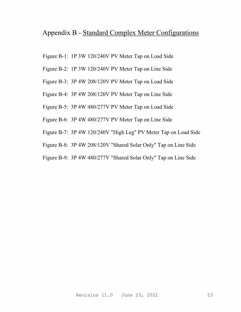
Revision 11.0 June 23, 2021 53
Appendix B - Standard Complex Meter Configurations
Figure B-1: 1P 3W 120/240V PV Meter Tap on Load Side Figure B-2: 1P 3W 120/240V PV Meter Tap on Line Side Figure B-3: 3P 4W 208/120V PV Meter Tap on Load Side Figure B-4: 3P 4W 208/120V PV Meter Tap on Line Side Figure B-5: 3P 4W 480/277V PV Meter Tap on Load Side Figure B-6: 3P 4W 480/277V PV Meter Tap on Line Side Figure B-7: 3P 4W 120/240V "High Leg" PV Meter Tap on Load Side Figure B-8: 3P 4W 208/120V "Shared Solar Only" Tap on Line Side Figure B-9: 3P 4W 480/277V "Shared Solar Only" Tap on Line Side
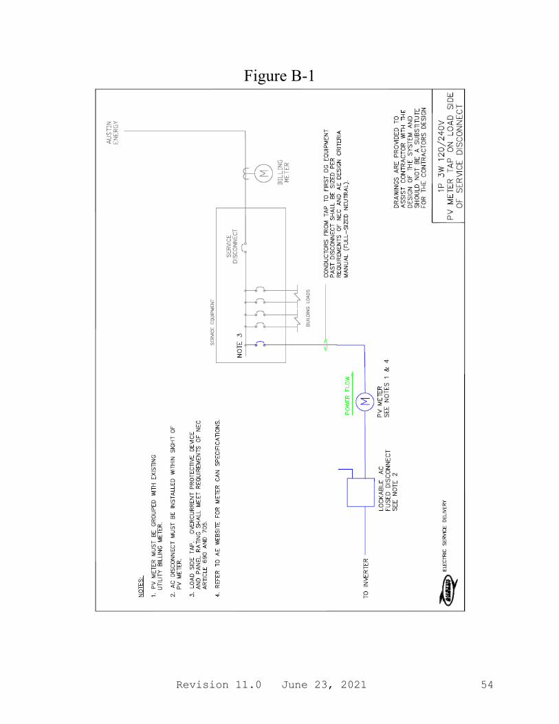
Revision 11.0 June 23, 2021 54
Figure B-1
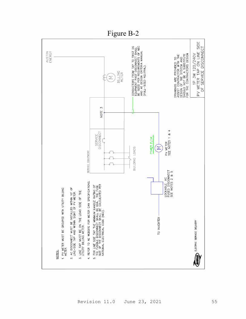
Revision 11.0 June 23, 2021 55
Figure B-2
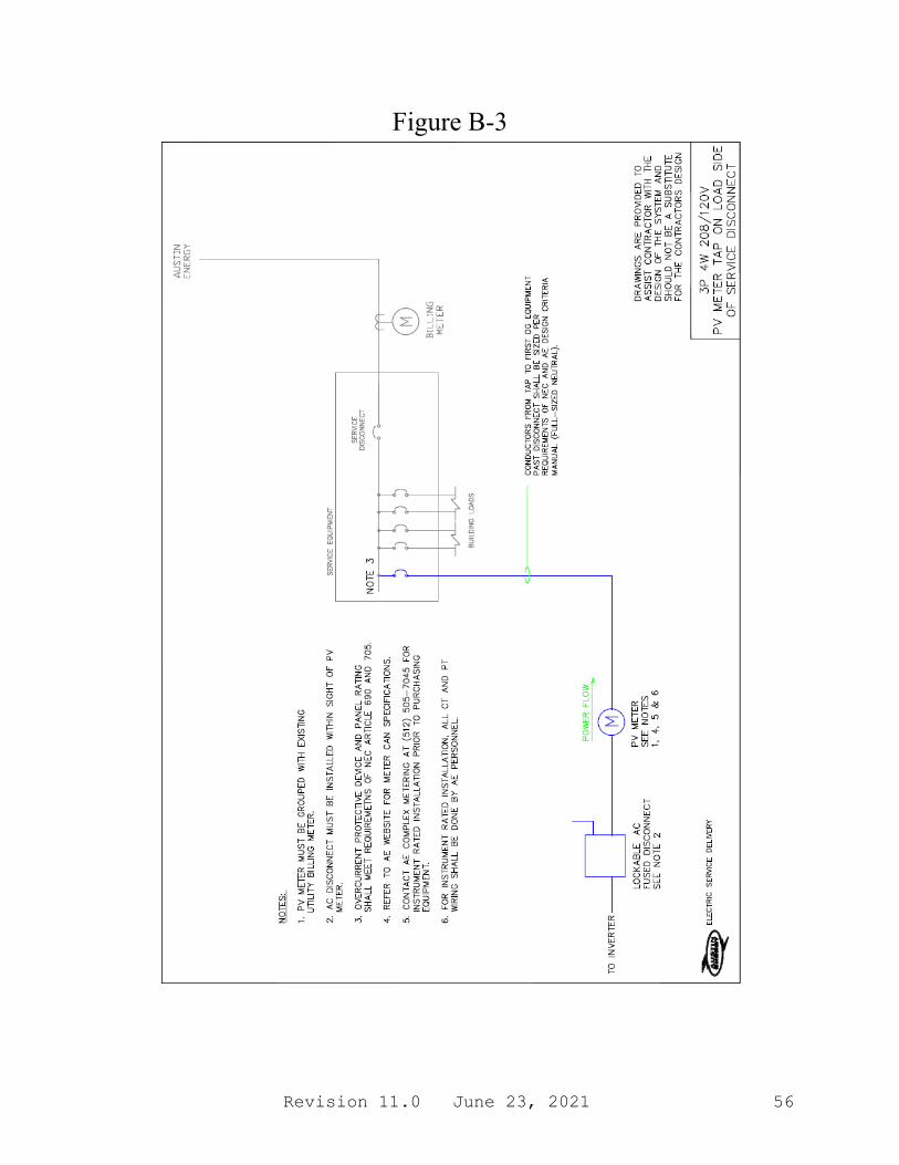
Revision 11.0 June 23, 2021 56
Figure B-3

Revision 11.0 June 23, 2021 57
Figure B-4
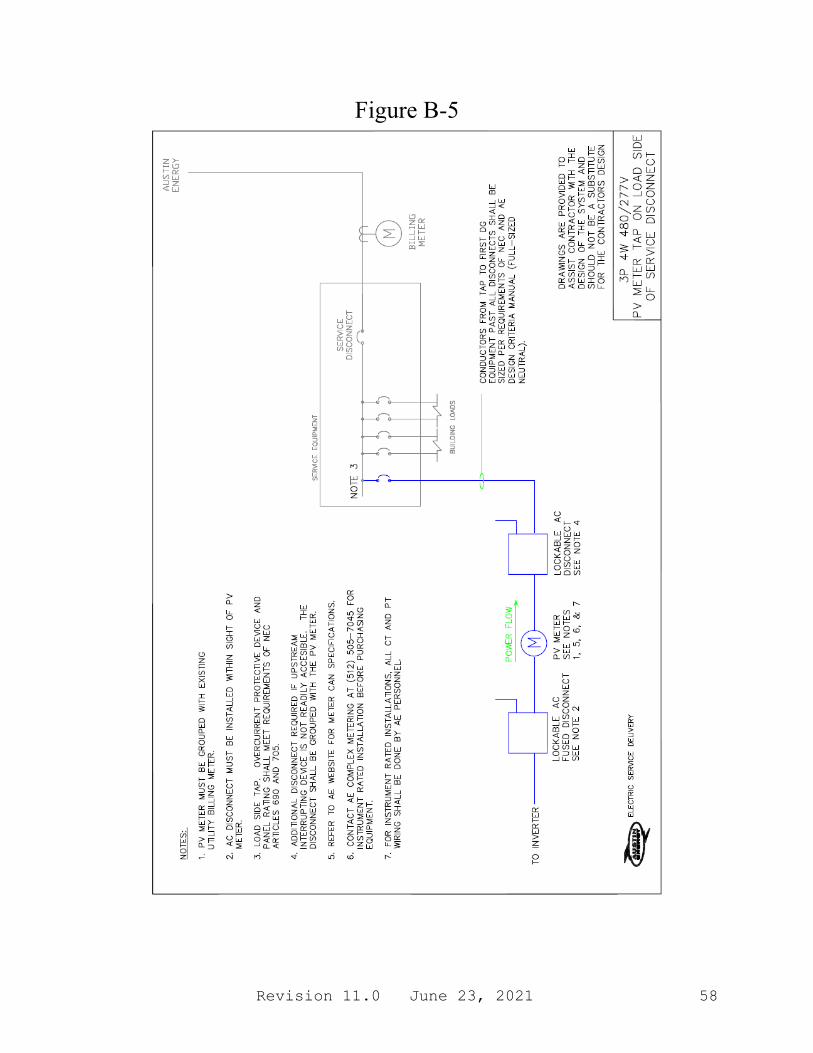
Revision 11.0 June 23, 2021 58
Figure B-5
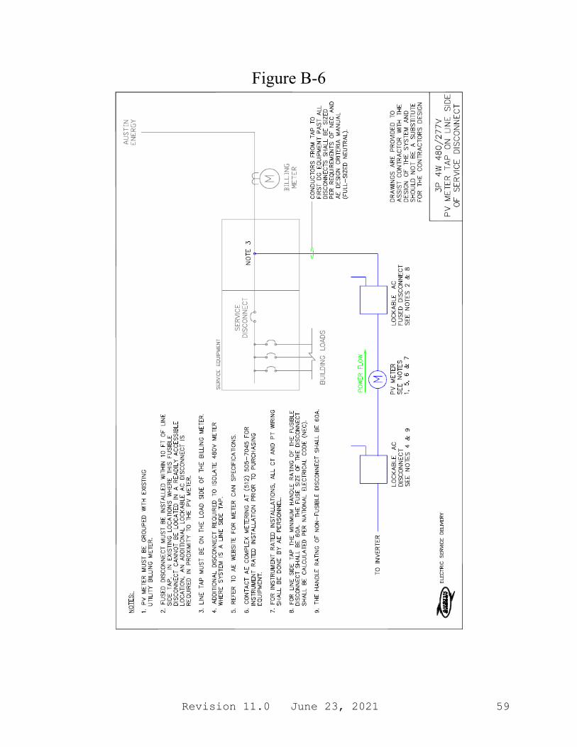
Revision 11.0 June 23, 2021 59
Figure B-6
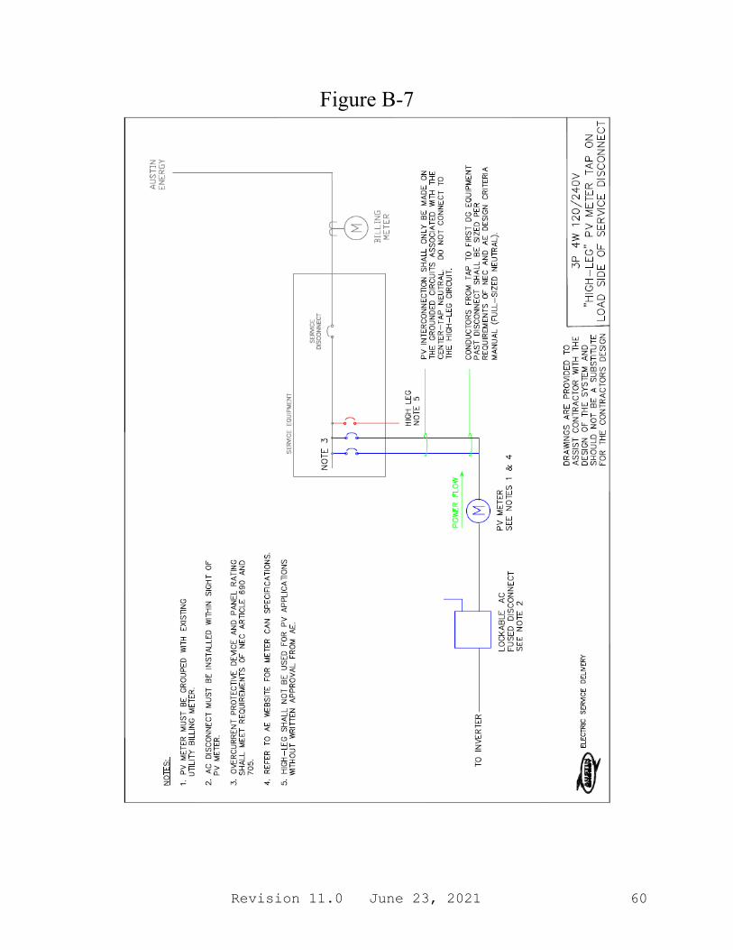
Revision 11.0 June 23, 2021 60
Figure B-7
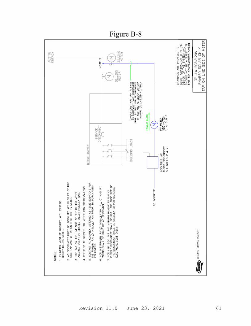
Revision 11.0 June 23, 2021 61
Figure B-8
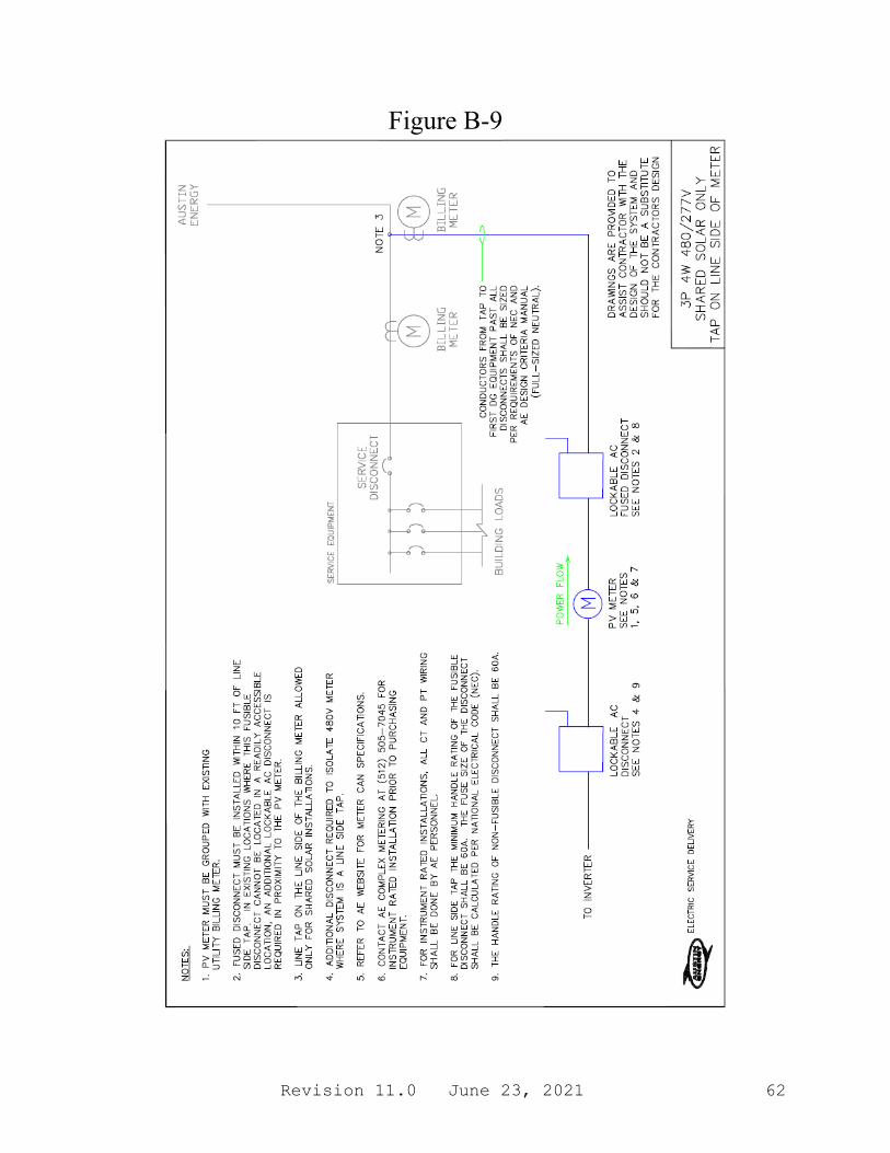
Revision 11.0 June 23, 2021 62
Figure B-9
Revision 11.0 June 23, 2021 63
Appendix C - AE DG/DER Inspection Checklist
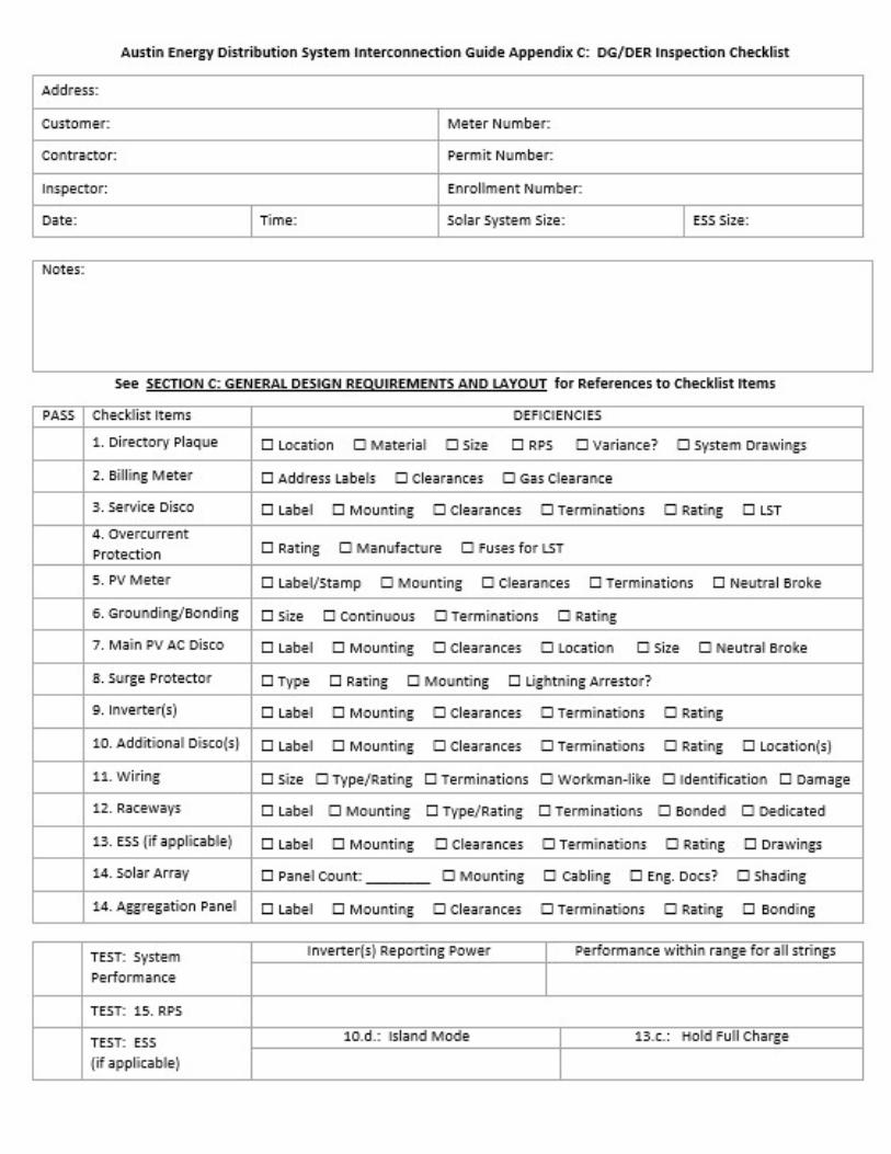
Revision 11.0 June 23, 2021 64

Revision 11.0 June 23, 2021 65
This page intentionally left blank

Revision 11.0 June 23, 2021 66
This page intentionally left blank
Revision 11.0 June 23, 2021 67
Appendix D Interconnection Application and Forms
For Systems 500 kW to <10 MW or on the Downtown Network

Revision 11.0 June 23, 2021 68
Application Checklist
1) Copy enclosed of approved DGPA Application indicating whether or not proposed facility is in
the Downtown Network.
2) Copy enclosed of completed Distributed Generation Application. a) Application form. b) Customer information. c) DG application--either PV or rotating machine sheets. d) Interconnecting facilities information. e) Interconnection Agreement (refer to in this section).
3) Copy enclosed of site electrical one-line diagram and schematic drawings showing the
configuration of all Distributed Generation equipment, current and potential circuits, and protection and control schemes, signed and stamped by a professional engineer licensed in the state of Texas.
4) Copy enclosed of any site documentation that indicates the precise physical location of the
proposed distributed generation facility (e.g., USGS topographic map or other diagram or documentation).
5) Copy enclosed of proposed location of Disconnect Switch(es) in relation to meter, generator,
and main service meter. 6) Copy enclosed of any site documentation that describes and details the operation of the
protection and control schemes, as well as proposed directory/plaque location. 7) Copy enclosed of schematic drawings for all protection and control circuits, relay current
circuits, relay potential circuits, and alarm/monitoring circuits (if applicable). 8) Enclosed certificate of insurance and initial payment per fee schedule (if applicable). (Refer to
Section E of this guide, notes 11 and 12). 9) Enclosed Signed Interconnection Agreement. 10) Upon completion of construction, schedule COA inspection at least 7 business days prior to
energizing DG system.
Applicant Signature I hereby certify that, to the best of my knowledge, all of the information provided in this Interconnection Request is true and correct. Interconnection Customer: _________________________________ Date:_________
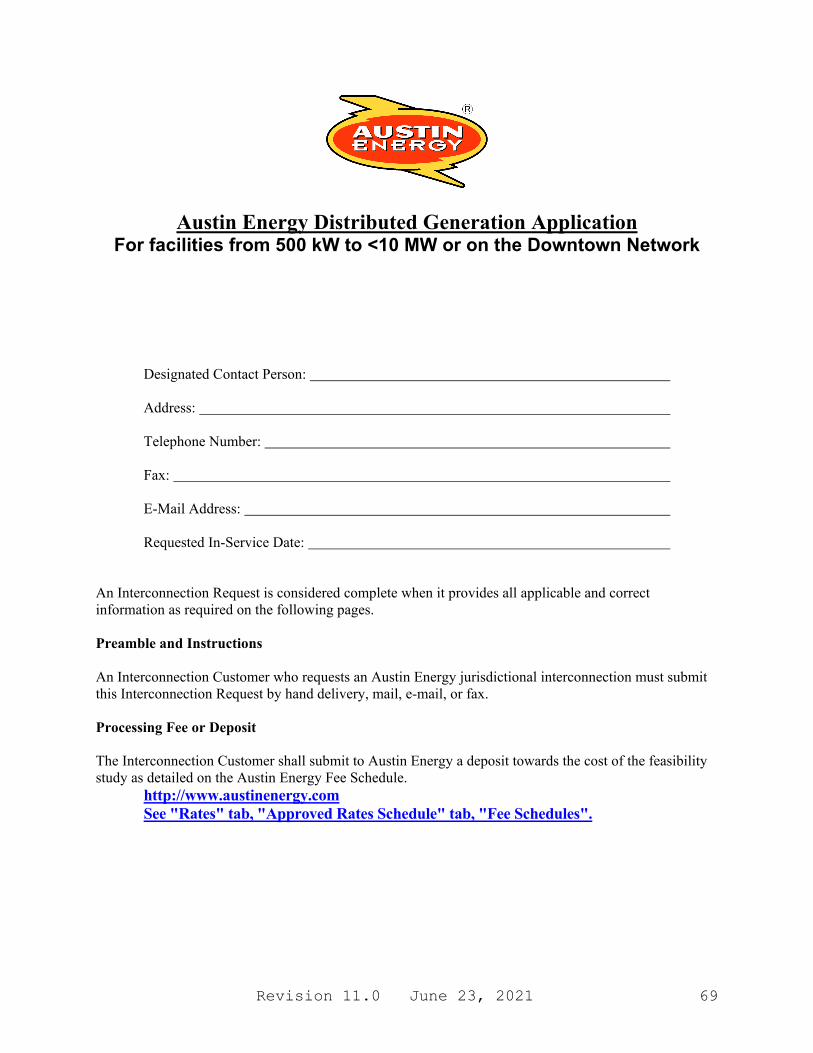
Revision 11.0 June 23, 2021 69
Austin Energy Distributed Generation Application For facilities from 500 kW to <10 MW or on the Downtown Network
Designated Contact Person:
Address:
Telephone Number: Fax:
E-Mail Address: Requested In-Service Date:
An Interconnection Request is considered complete when it provides all applicable and correct information as required on the following pages. Preamble and Instructions An Interconnection Customer who requests an Austin Energy jurisdictional interconnection must submit this Interconnection Request by hand delivery, mail, e-mail, or fax. Processing Fee or Deposit The Interconnection Customer shall submit to Austin Energy a deposit towards the cost of the feasibility study as detailed on the Austin Energy Fee Schedule.
http://www.austinenergy.com See "Rates" tab, "Approved Rates Schedule" tab, "Fee Schedules".
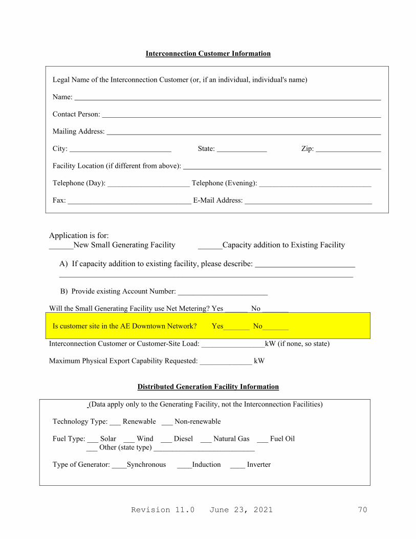
Revision 11.0 June 23, 2021 70
Interconnection Customer Information
Legal Name of the Interconnection Customer (or, if an individual, individual's name) Name: Contact Person: Mailing Address: City: State: Zip: Facility Location (if different from above): Telephone (Day): ______________________ Telephone (Evening): ______________________________ Fax: _________________________________ E-Mail Address: __________________________________
Application is for: ______New Small Generating Facility ______Capacity addition to Existing Facility A) If capacity addition to existing facility, please describe: ________________________________________________________________________ B) Provide existing Account Number: ________________________ Will the Small Generating Facility use Net Metering? Yes ______ No _______ Is customer site in the AE Downtown Network? Yes_______ No_______
Interconnection Customer or Customer-Site Load: _________________kW (if none, so state) Maximum Physical Export Capability Requested: ______________ kW
Distributed Generation Facility Information
(Data apply only to the Generating Facility, not the Interconnection Facilities)
Technology Type: ___ Renewable ___ Non-renewable Fuel Type: ___ Solar ___ Wind ___ Diesel ___ Natural Gas ___ Fuel Oil ___ Other (state type) ___________________________ Type of Generator: ____Synchronous ____Induction ____ Inverter
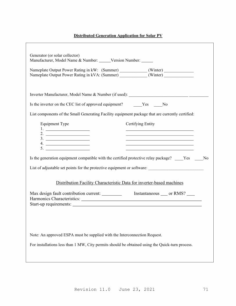
Revision 11.0 June 23, 2021 71
Distributed Generation Application for Solar PV
Generator (or solar collector) Manufacturer, Model Name & Number: Version Number: Nameplate Output Power Rating in kW: (Summer) _____________ (Winter) ______________ Nameplate Output Power Rating in kVA: (Summer) _____________ (Winter) ______________ Inverter Manufacturer, Model Name & Number (if used): ____________________________ _________ Is the inverter on the CEC list of approved equipment? ____Yes ____No List components of the Small Generating Facility equipment package that are currently certified:
Equipment Type Certifying Entity 1. 2. 3. 4. 5.
Is the generation equipment compatible with the certified protective relay package? ____Yes ____No List of adjustable set points for the protective equipment or software: __________________________
Distribution Facility Characteristic Data for inverter-based machines
Max design fault contribution current: Instantaneous or RMS? Harmonics Characteristics: Start-up requirements:
Note: An approved ESPA must be supplied with the Interconnection Request. For installations less than 1 MW, City permits should be obtained using the Quick-turn process.

Revision 11.0 June 23, 2021 72
Interconnection Facilities Information Part A - Transformer Will a transformer be used between the generator and the point of common coupling? ___Yes ___No Will the transformer be provided by the ____Interconnection Customer or ____AE? If transformer is provided by AE, the rest of part A (below) is left blank Transformer Data (for Customer-Owned Transformer only): Size: ___________kVA Transformer Impedance: _______% on __________kVA Base Transformer Primary: _____ Volts _____ Delta _____Wye _____ Wye Grounded Transformer Secondary: _____ Volts _____ Delta _____Wye _____ Wye Grounded Transformer Tertiary: _____ Volts _____ Delta _____Wye _____ Wye Grounded Transformer Fuse Data (if applicable): Manufacturer: __________________ Type: _______________ Size: ________Speed: ______________ Interconnecting Circuit Breaker (if applicable): Manufacturer: ____________________________ Type: __________ Load Rating (Amps): _______ Interrupting Rating (Amps): ________ Trip Speed (Cycles): __________ Interconnection Protective Relays (If Applicable): List of Functions and Adjustable Setpoints for the protective equipment or software:
Setpoint Function Minimum Maximum 1. 2. 3.
Part B - Reconnection Time Programmed Time Delay for Reconnection after Interruption: ___300 Seconds (default) ___Other (specify)__________

Revision 11.0 June 23, 2021 73
Distributed Generation Application for Rotating Machines (not required for Solar PV systems)
RPM Frequency: _____________ (*) Neutral Grounding Resistor (If Applicable): ____________ Synchronous Generators: Direct Axis Synchronous Reactance, Xd: _______ P.U. Direct Axis Transient Reactance, X' d: ___________P.U. Direct Axis Subtransient Reactance, X" d: ______________P.U. Negative Sequence Reactance, X2: _________ P.U. Zero Sequence Reactance, X0: ____________ P.U. KVA Base: __________________________ Field Volts: ______________ Field Amperes: ______________
Induction Generators: Motoring Power (kW): ______________ Locked Rotor current________________________ I2
2t or K (Heating Time Constant): ______________ Rotor Resistance, Rr: ______________ P.U. Stator Resistance, Rs: ______________ P.U. Stator Reactance, Xs: ______________ P.U. Rotor Reactance, Xr: ______________ P.U. Magnetizing Reactance, Xm: ______________ P.U. Short Circuit Reactance, Xd'': ______________ P.U. Exciting Current: ______________ Temperature Rise: ______________ Frame Size: ______________ Design Letter: ______________ Reactive Power Required In KVars (No Load): ______________ Reactive Power Required In KVars (Full Load): ______________ Total Rotating Inertia, H: _____________ Per Unit on kVA Base
Excitation and Governor System Data for Synchronous Generators Only: Individual Generator Power Factor Rated Power Factor: Leading: _____________Lagging: _______________
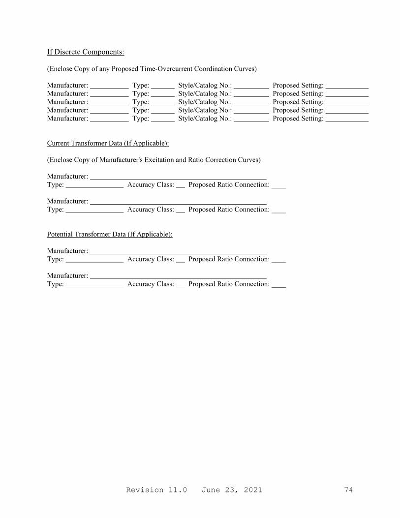
Revision 11.0 June 23, 2021 74
If Discrete Components: (Enclose Copy of any Proposed Time-Overcurrent Coordination Curves) Manufacturer: Type: Style/Catalog No.: Proposed Setting: Manufacturer: Type: Style/Catalog No.: Proposed Setting: Manufacturer: Type: Style/Catalog No.: Proposed Setting: Manufacturer: Type: Style/Catalog No.: Proposed Setting: Manufacturer: Type: Style/Catalog No.: Proposed Setting: Current Transformer Data (If Applicable): (Enclose Copy of Manufacturer's Excitation and Ratio Correction Curves) Manufacturer: Type: Accuracy Class: Proposed Ratio Connection: ____ Manufacturer: Type: Accuracy Class: Proposed Ratio Connection: ____ Potential Transformer Data (If Applicable): Manufacturer: Type: Accuracy Class: Proposed Ratio Connection: ____ Manufacturer: Type: Accuracy Class: Proposed Ratio Connection: ____
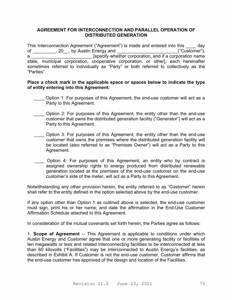
Revision 11.0 June 23, 2021 75
AGREEMENT FOR INTERCONNECTION AND PARALLEL OPERATION OF DISTRIBUTED GENERATION
This Interconnection Agreement (“Agreement”) is made and entered into this ____ day of _________, 20__, by Austin Energy and ________________________(“Customer”), a ________________________ [specify whether corporation, and if a corporation name state, municipal corporation, cooperative corporation, or other], each hereinafter sometimes referred to individually as “Party” or both referred to collectively as the “Parties”. Place a check mark in the applicable space or spaces below to indicate the type of entity entering into this Agreement:
____ Option 1: For purposes of this Agreement, the end-use customer will act as a Party to this Agreement.
____ Option 2: For purposes of this Agreement, the entity other than the end-use
customer that owns the distributed generation facility (“Generator”) will act as a Party to this Agreement.
____ Option 3: For purposes of this Agreement, the entity other than the end-use
customer that owns the premises where the distributed generation facility will be located (also referred to as “Premises Owner”) will act as a Party to this Agreement.
____ Option 4: For purposes of this Agreement, an entity who by contract is
assigned ownership rights to energy produced from distributed renewable generation located at the premises of the end-use customer on the end-use customer’s side of the meter, will act as a Party to this Agreement.
Notwithstanding any other provision herein, the entity referred to as “Customer” herein shall refer to the entity defined in the option selected above by the end-use customer. If any option other than Option 1 as outlined above is selected, the end-use customer must sign, print his or her name, and date the affirmation in the End-Use Customer Affirmation Schedule attached to this Agreement. In consideration of the mutual covenants set forth herein, the Parties agree as follows: 1. Scope of Agreement -- This Agreement is applicable to conditions under which Austin Energy and Customer agree that one or more generating facility or facilities of ten megawatts or less and related interconnecting facilities to be interconnected at less than 60 kilovolts (“Facilities”) may be interconnected to Austin Energy’s facilities, as described in Exhibit A. If Customer is not the end-use customer, Customer affirms that the end-use customer has approved of the design and location of the Facilities.
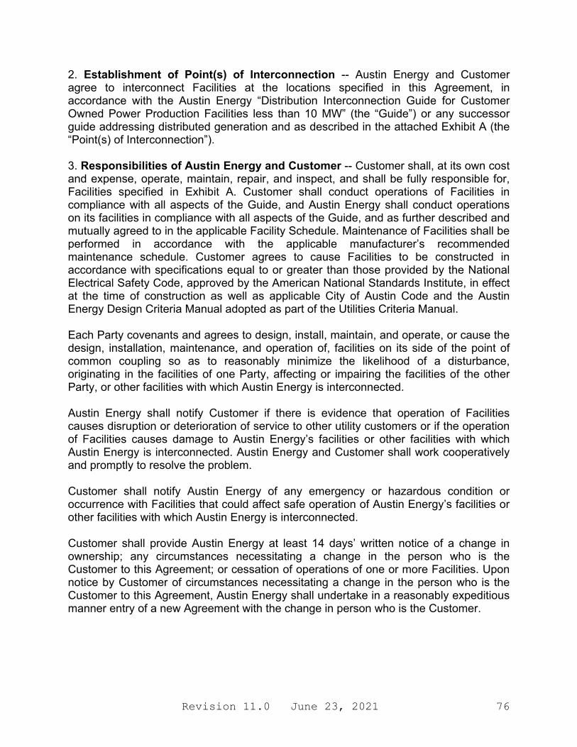
Revision 11.0 June 23, 2021 76
2. Establishment of Point(s) of Interconnection -- Austin Energy and Customer agree to interconnect Facilities at the locations specified in this Agreement, in accordance with the Austin Energy “Distribution Interconnection Guide for Customer Owned Power Production Facilities less than 10 MW” (the “Guide”) or any successor guide addressing distributed generation and as described in the attached Exhibit A (the “Point(s) of Interconnection”). 3. Responsibilities of Austin Energy and Customer -- Customer shall, at its own cost and expense, operate, maintain, repair, and inspect, and shall be fully responsible for, Facilities specified in Exhibit A. Customer shall conduct operations of Facilities in compliance with all aspects of the Guide, and Austin Energy shall conduct operations on its facilities in compliance with all aspects of the Guide, and as further described and mutually agreed to in the applicable Facility Schedule. Maintenance of Facilities shall be performed in accordance with the applicable manufacturer’s recommended maintenance schedule. Customer agrees to cause Facilities to be constructed in accordance with specifications equal to or greater than those provided by the National Electrical Safety Code, approved by the American National Standards Institute, in effect at the time of construction as well as applicable City of Austin Code and the Austin Energy Design Criteria Manual adopted as part of the Utilities Criteria Manual. Each Party covenants and agrees to design, install, maintain, and operate, or cause the design, installation, maintenance, and operation of, facilities on its side of the point of common coupling so as to reasonably minimize the likelihood of a disturbance, originating in the facilities of one Party, affecting or impairing the facilities of the other Party, or other facilities with which Austin Energy is interconnected. Austin Energy shall notify Customer if there is evidence that operation of Facilities causes disruption or deterioration of service to other utility customers or if the operation of Facilities causes damage to Austin Energy’s facilities or other facilities with which Austin Energy is interconnected. Austin Energy and Customer shall work cooperatively and promptly to resolve the problem. Customer shall notify Austin Energy of any emergency or hazardous condition or occurrence with Facilities that could affect safe operation of Austin Energy’s facilities or other facilities with which Austin Energy is interconnected. Customer shall provide Austin Energy at least 14 days’ written notice of a change in ownership; any circumstances necessitating a change in the person who is the Customer to this Agreement; or cessation of operations of one or more Facilities. Upon notice by Customer of circumstances necessitating a change in the person who is the Customer to this Agreement, Austin Energy shall undertake in a reasonably expeditious manner entry of a new Agreement with the change in person who is the Customer.

Revision 11.0 June 23, 2021 77
4. Limitation of Liability and Indemnification a. Customer shall indemnify, defend and hold harmless Austin Energy, its officers, employees, agents, city council members and other elected officials (each, an “Indemnified Party”) from and against all claims, demands, losses, liabilities, penalties, expenses (including reasonable attorneys’ fees and expenses), suits and proceedings of any nature whatsoever, for personal injury or death to natural persons and/or physical damage to tangible property of any Person, to the extent arising out of, resulting from, or caused by (i) violation of any applicable Legal Requirements by Customer, its directors, officers, employees, or agents; or (ii) the negligent or tortious acts, errors or omissions of Customer, its directors, officers, employees, or agents. This indemnification obligation shall apply notwithstanding any negligent or intentional acts, errors or omissions of the Indemnified Party, but Customer’s liability to pay damages to the Indemnified Party shall be reduced in proportion to the percentage by which the Indemnified Party’s negligent or intentional acts, errors or omissions caused the damages. Indemnified Party shall not be indemnified for its damages resulting from its sole negligence, intentional acts or willful misconduct. This indemnity provision shall not be construed to relieve any insurer of its obligation to pay claims consistent with the provisions of a valid insurance policy. b. Austin Energy and Customer shall each be responsible for the safe installation, maintenance, repair, and condition of their respective facilities on their respective sides of the Points of Interconnection. Austin Energy does not assume any duty of inspecting Customer’s Facilities. c. For the mutual protection of Customer and Austin Energy, only with Austin Energy prior authorization are the connections between Austin Energy’s service wires and Customer’s service entrance conductors to be energized. 5. Right of Access, Equipment Installation, Removal & Inspection -- Upon reasonable notice, Austin Energy may send a qualified person to the premises where the Facilities are located at or immediately before the time Facilities first produce energy to inspect the interconnection, and observe Facilities’ commissioning (including any testing), startup, and operation for a period of up to three days after initial startup of Facilities. Following the initial inspection process described above, at reasonable hours, and upon reasonable notice, or at any time without notice in the event of an emergency or hazardous condition, Austin Energy shall have access to the premises where the Facilities are located for any reasonable purpose in connection with the performance of the obligations imposed on it by this Agreement or if necessary to meet its legal obligation to provide service to its customers.
Revision 11.0 June 23, 2021 78
Customer warrants it has, or has obtained from other entities, all necessary rights to provide Austin Energy with access to the premises and Facilities, as necessary or appropriate for Austin Energy to exercise its rights under this Agreement and the Guide. 6. Disconnection of Facilities -- Customer retains the option to disconnect from Austin Energy’s facilities. Customer shall notify Austin Energy of its intent to disconnect by giving Austin Energy at least thirty days’ written notice. Such disconnection shall not be a termination of this Agreement unless Customer exercises rights under Section 7. Customer shall disconnect Facilities from Austin Energy’s facilities upon the effective date of any termination under Section 7. For routine maintenance and repairs of Austin Energy’s facilities, Austin Energy shall provide Customer with seven business days’ notice of service interruption. Austin Energy shall have the right to suspend service in cases where continuance of service to Customer will endanger persons or property. During the forced outage of Austin Energy’s facilities serving Customer, Austin Energy shall have the right to suspend service to effect immediate repairs of Austin Energy’s facilities, but Austin Energy shall use its best efforts to provide Customer with reasonable prior notice. 7. Effective Term and Termination Rights -- This Agreement becomes effective when executed by both Parties and shall continue in effect until terminated. The Agreement may be terminated for the following reasons: (a) Customer may terminate this Agreement at any time, by giving Austin Energy sixty days’ written notice; (b) Austin Energy may terminate upon failure by Customer to generate energy from Facilities in parallel with Austin Energy’s facilities within twelve months after the interconnection final inspection permit date; (c) either Party may terminate by giving the other Party at least sixty days written notice that the other Party is in default of any of the material terms and conditions of the Agreement, so long as the notice specifies the basis for termination and there is reasonable opportunity to cure the default; or (d) Austin Energy may terminate by giving Customer at least sixty days’ notice in the event that there is a material change in an applicable Guide, ordinance, rule or statute that necessitates termination of this Agreement. 8. Governing Law and Regulatory Authority -- This Agreement was executed in the State of Texas and must in all respects be governed by, interpreted, construed, and enforced in accordance with the laws thereof. This Agreement is subject to, and the parties’ obligations hereunder include, operating in full compliance with all valid, applicable federal, state, and local laws or ordinances, and all applicable rules, regulations, orders of, and tariffs approved by, duly constituted regulatory authorities having jurisdiction.
Revision 11.0 June 23, 2021 79
9. Amendment --This Agreement may be amended only upon mutual agreement of the Parties, which amendment will not be effective until reduced to writing and executed by the Parties. 10. Entirety of Agreement and Prior Agreements Superseded -- This Agreement, including the attached Exhibit A and Facility Schedules, which are expressly made a part hereof for all purposes, constitutes the entire agreement and understanding between the Parties with regard to the interconnection of the facilities of the Parties at the Points of Interconnection expressly provided for in this Agreement. The Parties are not bound by or liable for any statement, representation, promise, inducement, understanding, or undertaking of any kind or nature (whether written or oral) with regard to the subject matter hereof not set forth or provided for herein. This Agreement replaces all prior agreements and undertakings, oral or written, between the Parties with regard to the subject matter hereof, including without limitation ________________________________________________ [specify any prior agreements being superseded], and all such agreements and undertakings are agreed by the Parties to no longer be of any force or effect. It is expressly acknowledged that the Parties may have other agreements covering other services not expressly provided for herein, which agreements are unaffected by this Agreement.
Revision 11.0 June 23, 2021 80
11. Written Notices -- Written notices given under this Agreement are deemed to have been duly delivered if submitted via first class mail or email, to:
(a) If to Austin Energy:
Austin Energy System Engineering 2500 Montopolis Dr Austin, TX 78741 Email: [email protected]
(b) If to Customer: ______________________ ______________________ ______________________ ______________________
The above-listed names, titles, and addresses of either Party may be changed by written notification to the other, notwithstanding Section 10. 12. Invoicing and Payment -- Invoicing and payment terms for services associated with this agreement shall be consistent with applicable tariffs and fee schedules established by Austin Energy or the City of Austin. 13. Disclosure of Information to End-Use Customer -- If Customer is not the end-use customer, Austin Energy is hereby authorized to provide any information requested by the end-use customer concerning the Facility. 14. No Third-Party Beneficiaries -- This Agreement is not intended to and does not create rights, remedies, or benefits of any character whatsoever in favor of any persons, corporations, associations, or entities other than the Parties, and the obligations herein assumed are solely for the use and benefit of the Parties, their successors in interest and, where permitted, their assigns. 15. No Waiver -- The failure of a Party to this Agreement to insist, on any occasion, upon strict performance of any provision of this Agreement will not be considered to waive the obligations, rights, or duties imposed upon the Parties. 16. Headings -- The descriptive headings of the various parts of this Agreement have been inserted for convenience of reference only and are to be afforded no significance in the interpretation or construction of this Agreement. 17. Multiple Counterparts -- This Agreement may be executed in two or more counterparts, each of which is deemed an original but all constitute one and the same instrument.

Revision 11.0 June 23, 2021 81
IN WITNESS WHEREOF, the Parties have caused this Agreement to be signed by their respective duly authorized representatives. AUSTIN ENERGY [CUSTOMER NAME] BY:___________________________ BY:___________________________ PRINTED NAME PRINTED NAME ______________________________ _____________________________ TITLE:_________________________ TITLE:_________________________ DATE:_________________________ DATE:_________________________
Revision 11.0 June 23, 2021 82
EXHIBIT A
LIST OF FACILITY SCHEDULES AND POINTS OF INTERCONNECTION
Facility Schedule No. Name of Point of Interconnection
[Insert Facility Schedule number and name for each Point of Interconnection]
Revision 11.0 June 23, 2021 83
FACILITY SCHEDULE NO. [The following information is to be specified for each Point of Interconnection, if applicable.] 1. Customer Name: 2. Premises Owner Name: 3. Facility location: 4. Delivery voltage: 5. Metering (voltage, location, and other): 6. Normal Operation of Interconnection: 7. One line diagram attached (check one): ______ Yes /_______ No If Yes, then the one-line drawing should show the most current drawing(s) available as of the signing of this Schedule. Austin Energy and Customer agree drawing(s) may be updated to meet as built or design changes that occur during construction. Customer understands and agrees that any changes that substantially affect the protective or functional requirements required by Austin Energy will need to be reviewed and accepted by Austin Energy. 8. Equipment to be furnished by Austin Energy: (This section is intended to generally describe equipment to be furnished by Austin Energy to effectuate the interconnection and may not be a complete list of necessary equipment.) 9. Equipment to be furnished by Customer: (This section is intended to describe equipment to be furnished by Customer to effectuate the interconnection and may not be a complete list of necessary equipment.)
Revision 11.0 June 23, 2021 84
10. Cost Responsibility and Ownership and Control of Austin Energy Facilities: Unless otherwise agreed or prescribed by applicable regulatory requirements or other law, any payments received by Austin Energy from Customer will remain the property of Austin Energy. Austin Energy shall at all times have title and complete ownership and control over facilities installed by Austin Energy. 11. Modifications to Customer Facilities. Customer understands and agrees that, before making any modifications to its Facilities that substantially affect the protective or interconnection parameters or requirements used in the interconnection process (including in an Pre-interconnection Study performed by Austin Energy), Customer will both notify Austin Energy of, and receive approval by Austin Energy for, such modifications. Customer further understands and agrees that, if required pursuant to the requirements found in this Agreement, it will submit a new Application for Interconnection and Parallel Operation request for the desired modifications. 12. Supplemental terms and conditions attached (check one): _____ Yes / ______ No

Revision 11.0 June 23, 2021 85
END-USE CUSTOMER AFFIRMATION SCHEDULE The end-use customer selecting the entity who owns the DG facility (the DG owner or Option 2 entity), the owner of the premises at which the DG facility is located (premises owner or Option 3 entity), or the person who by contract is assigned ownership rights to energy produced by the DG facility (Option 4 entity) to act as Customer and Party to the Interconnection Agreement must sign and date the consent below.
“I affirm that I am the end-use customer for the distributed generation facility addressed in Facility Schedule No. __[insert applicable number] in the Interconnection Agreement between Austin Energy and ___________[insert name of Customer], and that I have selected _______ [insert name of Customer] or successor in interest to act as Customer and a Party to this Interconnection Agreement rather than me.
[END-USE CUSTOMER NAME]
SIGNATURE: ____________________________________
DATE: __________________________________________
Revision 11.0 June 23, 2021 86
This page intentionally left blank

Revision 11.0 June 23, 2021 87
Appendix E Network Interconnection Specifications
Revision 11.0 June 23, 2021 88
This page intentionally left blank
Revision 11.0 June 23, 2021 89
1. Purpose This appendix to the Austin Energy “Distribution System Interconnection Guide” will detail the requirements, safeguards, modeling, and performance criteria that are required for successfully integrating distributed generation (DG), typically Solar PV, operating at less than 1000 VAC on the Downtown Network, that meet all of the initial requirements in Section B.3. Please refer to Appendix A of the guide for a map of the Secondary (Downtown) Network. The requirements shall be met at the point of common coupling although the devices used to meet the requirements can be located elsewhere. This specification does not address self-protection of the DG or provide any safeguard to the operating facility as that is the responsibility of the DG owner. Implementation of DG on the network fundamentally affects the design of the network and may result in outages to the customer. The customer is required to acknowledge and accept that outages may occur, and Austin Energy will not be liable for any damages to the DG system, or outages that are a result of the customer's DG system backfeeding the AE system, since although the methods outlined in this section are fairly detailed, they do not guarantee the system will never backfeed. This specification does not address financial impacts as a result of curtailing generation during periods of low customer loads. It is the responsibility of the customer to understand the impact to the generation capability, and Austin Energy will not be liable for any loss of generation as a result of curtailment systems required to interconnect the system. 2. References (covered in Section G as well)
• IEEE 1547 - IEEE Standard for Interconnection and Interoperability of Distributed Energy Resources with Associated Electric Power Systems Interfaces.
• IEEE 1547.6 - IEEE Recommended Practice for Interconnecting Distributed Resources with Electric Power Systems Distribution Secondary Networks.
• IEEE C37.108 - Guide for the Protection of Network Transformers.
• IEEE C57.12.44 - Standard Requirements for Secondary Network Protectors.
• ANSI C84.1 - Electric Power Systems and Equipment. 3. Introduction and Background Secondary Networks were not designed to accommodate generation of any kind. They were designed to provide highly reliable service to dense urban areas by putting multiple feeders in parallel. For safety reasons, they are designed to intercept and react to faults that could cause backfeed on the network system, and as a result, network protectors (NP) are designed to instantaneously open upon detecting a reverse current flow. Distributed generation can be installed, as long as steps are taken to ensure that backfeed will not occur.

Revision 11.0 June 23, 2021 90
All DG on the secondary network must be inverter-based and less than 2 MW. Typical synchronous or induction generators can easily contribute fault currents that exceed a network protector's rating. Note: Emergency or standby generators may not utilize closed-transition transfer switches where facilities are connected to the Downtown Network. 4. Fundamental Design Requirements The primary concern about tripping network protectors is that they operate by interrupting current flow using spring-loaded finger contacts, so as a result, their lifetimes are typically a limited number of operations, compared to an average circuit breaker which has almost unlimited operations. In addition, network protectors (NP) are not designed or tested for interrupting increased fault currents, so these restrictions have led to some fundamental requirements as outlined in IEEE Standard 1547.6, Section 6:
• DG may not cause any NP to exceed its fault interrupting capability. • DG may not cause any NP to separate two dynamic sources. • DG may not cause any NP to connect two dynamic systems together. • DG may not cause any NP to operate more frequently than prior to DG operation. • DG may not prevent or delay the NP from opening for faults on the network feeders. • DG may not delay or prevent NP closure. • DG may not energize a de-energized network. • DG may not require the NP settings to be adjusted except by consent of the area EPS
operator. • DG may not cause an islanding condition within part of a grid network. • DG may not remain connected to the network if 50% or more of the NP's serving the
network are open. Distributed generation on a secondary spot network must be designed with all above requirements taken into consideration.
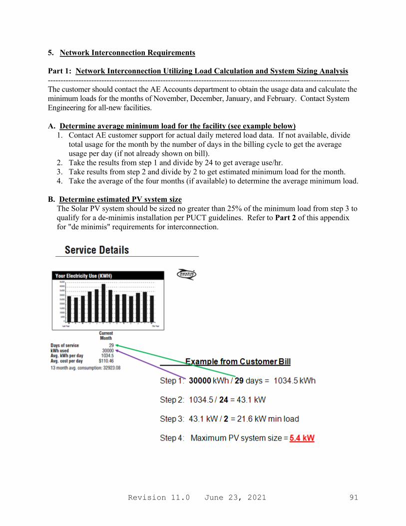
Revision 11.0 June 23, 2021 91
5. Network Interconnection Requirements Part 1: Network Interconnection Utilizing Load Calculation and System Sizing Analysis ---------------------------------------------------------------------------------------------------------------------- The customer should contact the AE Accounts department to obtain the usage data and calculate the minimum loads for the months of November, December, January, and February. Contact System Engineering for all-new facilities. A. Determine average minimum load for the facility (see example below)
1. Contact AE customer support for actual daily metered load data. If not available, divide total usage for the month by the number of days in the billing cycle to get the average usage per day (if not already shown on bill).
2. Take the results from step 1 and divide by 24 to get average use/hr. 3. Take results from step 2 and divide by 2 to get estimated minimum load for the month. 4. Take the average of the four months (if available) to determine the average minimum load.
B. Determine estimated PV system size
The Solar PV system should be sized no greater than 25% of the minimum load from step 3 to qualify for a de-minimis installation per PUCT guidelines. Refer to Part 2 of this appendix for "de minimis" requirements for interconnection.
Revision 11.0 June 23, 2021 92
Part 2: Network Interconnection Utilizing “de minimis” Method -------------------------------------------------------------------------------------- Conceptually, the goal of “de minimis” interconnection is not that complex - the distributed generation must not generate more than the facility load at any given time to prevent backfeeding and tripping a network protector, as described in Section 7 of IEEE 1547.6. This is achieved by sizing the distributed generation small enough so that it is unlikely that the load drops below the generation during operational hours, resulting in backfeed. Part 3: Network Interconnection Utilizing "Dynamic Controls" or Alternate Methods ------------------------------------------------------------------------------------------------------------------- To prevent backfeeding which will trip a Network Protector, a solar PV system must not generate more than the facility load at any given time. This can be achieved through dynamically controlled inverters which are interfaced to a digital control system that instantaneously monitors dynamic generation and utility supply and modulates generation to maintain a defined minimum forward current flow through the network protectors. 6. Control System Design Requirements Only contractors with a minimum of 2 years of experience installing commercial Solar PV systems should attempt the design and execution of a system interfaced to the downtown network for safety reasons, due to the complexity of the installation, as well as the high fault currents involved. The solar contractor is also responsible for contracting for engineering services to perform the design of the control system. The engineer must be licensed in the state of Texas.
• The control system shall have a minimum import relay installed, which should continuously monitor both the generation and utility supply, set to maintain a 3:1 ratio of utility supplied power to on-site generation. If the customer load drops so that the utility supply is below this 3:1 ratio, the relay should send a signal to the inverter to either reduce or disable generation.
• The control system must have a backup minimum import relay installed along with a
shunt trip electronically reclosable breaker set to a minimum forward current in case the primary control system fails.
• All CT’s shall be metering accuracy class.
• The network protectors shall be monitored by AE, and loss of any network protector shall result in loss of a control signal that will shut down the inverter(s). The solar contractor shall provide a wet (24VDC) signal to AE to route to the network protectors and then return to a dry contact on the inverter. Loss of this signal shall cause the inverters to shut down.
Revision 11.0 June 23, 2021 93
• It is recommended that the control system be remotely connected via Ethernet to enable
remote diagnostics by the contractor. Refer to Figure E-1 on Page 86 for a conceptual diagram of the system and controls.
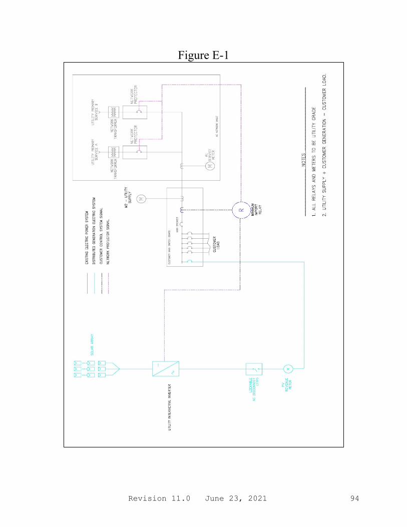
Revision 11.0 June 23, 2021 94
Figure E-1
Revision 11.0 June 23, 2021 95
7. Design, Installation, and Commissioning Requirements Once the system size and control setpoints have been defined, basic design drawings and documents shall be submitted for approval per the Interconnection process. The overall system one-line diagram, three-line diagram, System Instrument and Control schematic, including complete controls narrative, and a control wiring diagram shall be submitted for joint review. All drawings should be sealed by an electrical engineer licensed in the state of Texas. A commissioning test for the proposed installation will be jointly developed based on the final system design and intended operation. After installation, the system will not be energized for testing prior to the commissioning test. 8. Maintenance and Operation Requirements There should be a short review of the system after the first 6 months of operation. The requirement is for there to be zero actuation of the network protectors caused by the DG. Note that in normal operation, AE will occasionally open network protectors for maintenance activities and these actuations will not be considered being caused by the DG. Failure of the control system, resulting in backfeed that trips the network protectors, will result in the system being locked out by AE until the contractor can review and modify the control system with new setpoints, and the commissioning tests repeated to validate the new settings. It is the customer’s responsibility to ensure the control system does not trip the network protectors. Therefore, a long-term maintenance contract for the control system is strongly recommended so the customer can reap the projected economic benefit of the system.

Revision 11.0 June 23, 2021 96
This page intentionally left blank
Revision 11.0 June 23, 2021 97
Appendix F Emergency Response Service (ERS) Application
Revision 11.0 June 23, 2021 98
This page intentionally left blank

Revision 11.0 June 23, 2021 99
1. ERCOT Emergency Response Service (ERS) Process This process applies to ALL customers served by the AE Electrical System AE Customer Participation Requirements:
• Load Shed ERS customers will not require any technical approval.
• Load Shed with Generation will require a simple review to verify that the generation is not paralleled with the AE Distribution system.
• ERS Generation utilizing Parallel generation on the AE Distribution system must be approved by Austin Energy System Engineering Department. Refer to the main sections of this guide for details on that process.
• ERS Generation utilizing Parallel generation on the AE Transmission system must be approved by Austin Energy Substation & Transmission Engineering & Construction Department. Key Accounts will be the point of contact.
• Closed-transition transfer-switching is not permitted for customers on the Downtown Network. (Refer to Appendix A.) All non-network customers shall refer to "Distribution System Interconnection Guide for Customer Owned Power Production Facilities less than 10 MW" for interconnection requirements.
• Austin Energy prohibits accessing or modifying utility meters and CT enclosures. Customer based sub-metering CT’s may not be used in Austin Energy equipment.
If you are interested in AE’s Qualified Scheduling Entity (QSE) representing you in the ERS Program:
• Contact AE Key Accounts at 512-972-7637. • Key Accounts will determine which type of ERS program is best for you. • Key Accounts will assist you in completing and submitting "Exhibit F - ERS Application Form" to AE. • System Engineering will review Exhibit F and approve or request additional information and/or
clarification. If you already have a third party QSE representing you in the ERS program:
• Please follow the process outlined on the next page. • AE’s System Engineering group will perform a technical review of your application and facility and
approve or request additional information and/or clarification. Application Checklist for ERS Load Customers with Generator
1) Completed ERS Application and Interconnection Application (if required). 2) Copy enclosed of site electrical one-line diagram and schematic drawings showing the configuration of all
generation equipment, current and potential circuits, and protection and control schemes. 3) Copy enclosed of any site documentation that indicates the precise physical location of the proposed
generation facility (e.g., USGS topographic map or other diagram or documentation).
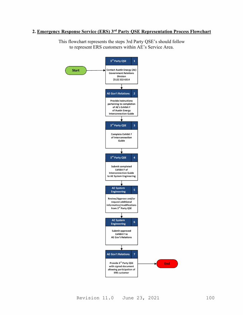
Revision 11.0 June 23, 2021 100
2. Emergency Response Service (ERS) 3rd Party QSE Representation Process Flowchart
This flowchart represents the steps 3rd Party QSE’s should follow to represent ERS customers within AE’s Service Area.

Revision 11.0 June 23, 2021 101
3. Exhibit F- ERS APPLICATION FORM
ERS Customer Information
Designated Contact Person:
Address:
Telephone Number:
E-Mail Address:
Customer Name:
Location Address:
Facility Phone # (Day/night):
Facility E-Mail Address:
ERS RESOURCE Nameplate Rating of generator (if applicable): ___________(MW) Contract Time Period:
TP1 (5:00AM TO 9:00AM) Maximum Offer: ______(kW) Load Description: _________________________________
ERS-10 Weather-Sensitive ERS-30 Weather-Sensitive ERS-10 Non-Weather-Sensitive
ERS-30 Non-Weather-Sensitive
TP2 (9:00AM TO 1:00PM) Maximum Offer: ______(kW) Load Description: _________________________________
ERS-10 Weather-Sensitive ERS-30 Weather-Sensitive ERS-10 Non-Weather-Sensitive
ERS-30 Non-Weather-Sensitive
TP3 (1:00PM TO 4:00PM) Maximum Offer: ______(kW) Load Description: _________________________________
ERS-10 Weather-Sensitive ERS-30 Weather-Sensitive ERS-10 Non-Weather-Sensitive
ERS-30 Non-Weather-Sensitive
TP4 (4:00PM TO 7:00PM) Maximum Offer: ______(kW) Load Description: _________________________________
ERS-10 Weather-Sensitive ERS-30 Weather-Sensitive ERS-10 Non-Weather-Sensitive
ERS-30 Non-Weather-Sensitive
TP5 (7:00PM TO 10:00PM) Maximum Offer: ______(kW) Load Description: _________________________________
ERS-10 Weather-Sensitive ERS-30 Weather-Sensitive ERS-10 Non-Weather-Sensitive
ERS-30 Non-Weather-Sensitive
TP6 (5:00AM TO 9:00AM) Maximum Offer: ______(kW) Load Description: _________________________________
ERS-10 Weather-Sensitive ERS-30 Weather-Sensitive ERS-10 Non-Weather-Sensitive
ERS-30 Non-Weather-Sensitive
TP7 (3:00PM TO 9:00PM) Maximum Offer: ______(kW) Load Description: _________________________________
ERS-10 Weather-Sensitive ERS-30 Weather-Sensitive ERS-10 Non-Weather-Sensitive
ERS-30 Non-Weather-Sensitive
TP8 (All Other Hours) Maximum Offer: ______(kW) Load Description: _________________________________
ERS-10 Weather-Sensitive ERS-30 Weather-Sensitive ERS-10 Non-Weather-Sensitive
ERS-30 Non-Weather-Sensitive

Revision 11.0 June 23, 2021 102
Applicant Signature I hereby certify and acknowledge that, to the best of my knowledge, all of the information provided in this ERS Application is true and correct.
QSE Company: (print) QSE Representative: Date:
ERS Customer: Date: Austin Energy System Engineering Review Reviewed Resubmit
Meter ID Service Point ID: Feeder:
Revision 11.0 June 23, 2021 103
Appendix G Electric Vehicle Connection Guide for Residential Customers
Revision 11.0 June 23, 2021 104
This page intentionally left blank
Revision 11.0 June 23, 2021 105
1. Purpose The Austin Energy “Electric Vehicle Connection Guide for Residential Customers” is to provide guidelines and configurations for connecting plug-in electric vehicles (PEVs) to a residential Time-of-Use (TOU) metering system. The guide contains information on application processes, technical requirements, applicable codes, metering configurations, and rate structures. Customers will have the option of getting their Electric Vehicle (EV) usage on a separate meter with a Time-of-Use rate. Otherwise, customers can keep their EV load as part of their whole house consumption for the standard rate. For Time of Use metering, apply for a residential sub-meter (EV Meter) thru the AE program. The Rate Structure for Time of Use metering can be found at the following:
http://www.austinenergy.com • Select the “Programs” tab • Select the “Plug-In Austin” tab
2. Electric Vehicle (EV) Charging Basics Power is delivered to the Electric Vehicle (EV) onboard battery through the EV inlet to the charger. The charger converts Alternating Current (AC) from the home to the Direct Current (DC) required to charge the battery in the vehicle. The charger and EV inlet are considered part of the EV. A connector is a device that, by insertion into an EV inlet, establishes an electrical connection to the EV for the purpose of charging and information exchange. The EV inlet and connector together are referred to as the coupler. The Electric Vehicle Supply Equipment (EVSE) consists of the connector, cord, and interface to utility power. The interface between the EVSE and utility power will generally be a plug and receptacle. At the present time, the Society of Automotive Engineers (SAE) has agreed that all vehicles produced by automakers in the United States will conform to a single design, known as the J1772 Standard. 3. Connection Classifications For Austin Energy designations, there are two classifications of connection to Electric Vehicles. They are as follows: (1) Level 1 and Level 2 <10 kW and (2) Level 2 >10 kW. For Level 1, 120 volt AC, the system uses a standard 120 volt AC branch circuit, which is the lowest common voltage level found in residential areas. Typical amp ratings for these receptacles are 15 or 20 amps. All EVs come equipped with Level 1 chargers from auto manufacturers. It is the slowest, but simplest, charging. For Level 2 <10 kW, 240 volt AC, the system is typically described as the “primary” and “standard” system for the EVSE for both private and publicly available facilities. This system specifies a single-phase branch circuit. A typical circuit rating would be 40 amps.
Revision 11.0 June 23, 2021 106
For Level 2 >10 kW, 240 volt AC, the system allows a much faster battery charge, but Level 2 has a higher level of safety requirements than Level 1 under the National Electrical Code (NEC), including the requirement that the connector and cord be hardwired to the control device and premises wiring in certain cases. The J1772-approved connector allows current as high as 80 amps (100 amp rated circuit). Level 2 charging (240 volts, maximum 80 amps) usually requires a dedicated circuit and will most likely require an electrical panel upgrade. 4. Application Processes for Electric Vehicle Connections The customer/contractor is required to obtain an electrical permit for construction of any facility interfaced to the AE system per Austin Electrical Code Section §25-12-111. This applies to all entities served by Austin Energy: residential, commercial, and government agencies. All procedures for obtaining a City of Austin (COA) electrical permit apply regardless if the system in installed within Austin or a separate extraterritorial jurisdiction (ETJ). The system must be installed in compliance with the National Electrical Code (NEC), NFPA 70.
Revision 11.0 June 23, 2021 107
4.1. Process for Residential Systems – Level 1 and Level 2 <10 kW Residential Systems less than 10 kW are generally required to have Electric Service Planning Applications (ESPA) only for upgrades to the main electrical service. Residential systems may require electrical permitting. A COA electrical permit must be pulled for the installation of a 240-volt charging station that is hard wired into the home, or the installation of a 240-volt receptacle for which to plug a Level 2 charging station into. Residential systems less than 10 kW should use the following process for obtaining a permit. Systems in this category are typically handled through the AE One-Stop Shop which can be reached at:
One-Stop Shop: (512) 974-9112 (or)
the preferred contact is via email which is at: One-Stop Shop email: [email protected]
a. The customer is required to submit an ESPA for review for connection to the AE system
only for upgrades to the main electrical service. Generally, it should still be submitted for tracking purposes. It can be found on the AE website at (or call AE Customer Service at 512-494-9400):
http://www.austinenergy.com • Select the “Contractors” tab • Select the “Electric Service Design & Planning” tab • Select “Learn More About Submitting an ESPA” • Select “View and Download the ESPA”
b. If the customer is required to go through plan review for obtaining an electrical permit,
the ESPA must be accompanied with a full set of drawings. Call COA Plan Review at 512-978-4000.
c. Upon successful completion of the process, the contractor will receive an electrical permit. Contact the COA Permit Center at 512-974-2747.
d. Contractor builds system and installs residential EV Meter circuit. Note: Any significant change in the design must go back through the plan review process.
e. After the system is installed, the contractor shall request the final electrical inspection from
the COA Electrical Inspection department via AMANDA or call 512-480-0623. Permit is then released.
f. Austin Energy sets the EV Meter and the process is complete. Call AE Metering at 512-505-7045.
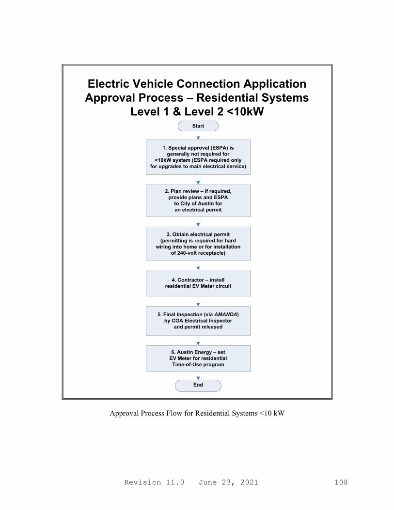
Revision 11.0 June 23, 2021 108
5. Final inspection (via AMANDA) by COA Electrical Inspector
and permit released
Electric Vehicle Connection Application Approval Process – Residential Systems
Level 1 & Level 2 <10kW
End
3. Obtain electrical permit (permitting is required for hard
wiring into home or for installation of 240-volt receptacle)
Start
2. Plan review – if required, provide plans and ESPA
to City of Austin for an electrical permit
6. Austin Energy – set EV Meter for residential Time-of-Use program
4. Contractor – install residential EV Meter circuit
1. Special approval (ESPA) is generally not required for
<10kW system (ESPA required only for upgrades to main electrical service)
Approval Process Flow for Residential Systems <10 kW
Revision 11.0 June 23, 2021 109
4.2. Process for Residential Systems – Level 2 >10 kW Residential Systems greater than 10 kW are required to have Electric Service Planning Applications (ESPA) for upgrades to the main electrical service. Residential systems may require electrical permitting. A COA electrical permit (but not an ESPA) must be pulled for the installation of a 240-volt charging station that is hard wired into the home, or the installation of a 240-volt receptacle for which to plug a Level 2 charging station into. Residential systems greater than 10 kW should use the following process for obtaining a permit. Systems in this category are typically handled through the AE Distribution Design groups which can be reached at:
One-Stop Shop: (512) 974-9112 (or)
the preferred contact is via email which is at: One-Stop Shop email: [email protected]
a. The customer is required to submit an ESPA for review for connection to the AE
system for upgrades to the main electrical service. It can be found on the AE website at (or call AE Customer Service at 512-494-9400): http://www.austinenergy.com
• Select the “Contractors” tab • Select the “Electric Service Design & Planning” tab • Select “Learn More About Submitting an ESPA” • Select “View and Download the ESPA”
b. If the customer is required to go through plan review for obtaining an electrical
permit, the ESPA must be accompanied with a full set of drawings. Call COA Plan Review at 512-978-4000.
c. Upon successful completion of the process, the contractor will receive an electrical
permit. Contact the COA Permit Center at 512-974-2747.
d. Contractor builds system and installs residential EV Meter circuit. Note: Any significant change in the design must go back through the plan review process.
e. After the system is installed, the customer/contractor shall request the electrical pre-
inspection from the COA Electrical Inspection department via AMANDA or call 512-480-0623. Pre-inspection covers only the transformer and concrete encased electrode and trench (only if needed).
f. The contractor shall request the final electrical inspection from the COA Electrical
Inspection department via AMANDA or call 512-480-0623. Permit is then released.
g. Austin Energy sets the EV Meter and the process is complete. Call AE Metering at 512-505-7045.
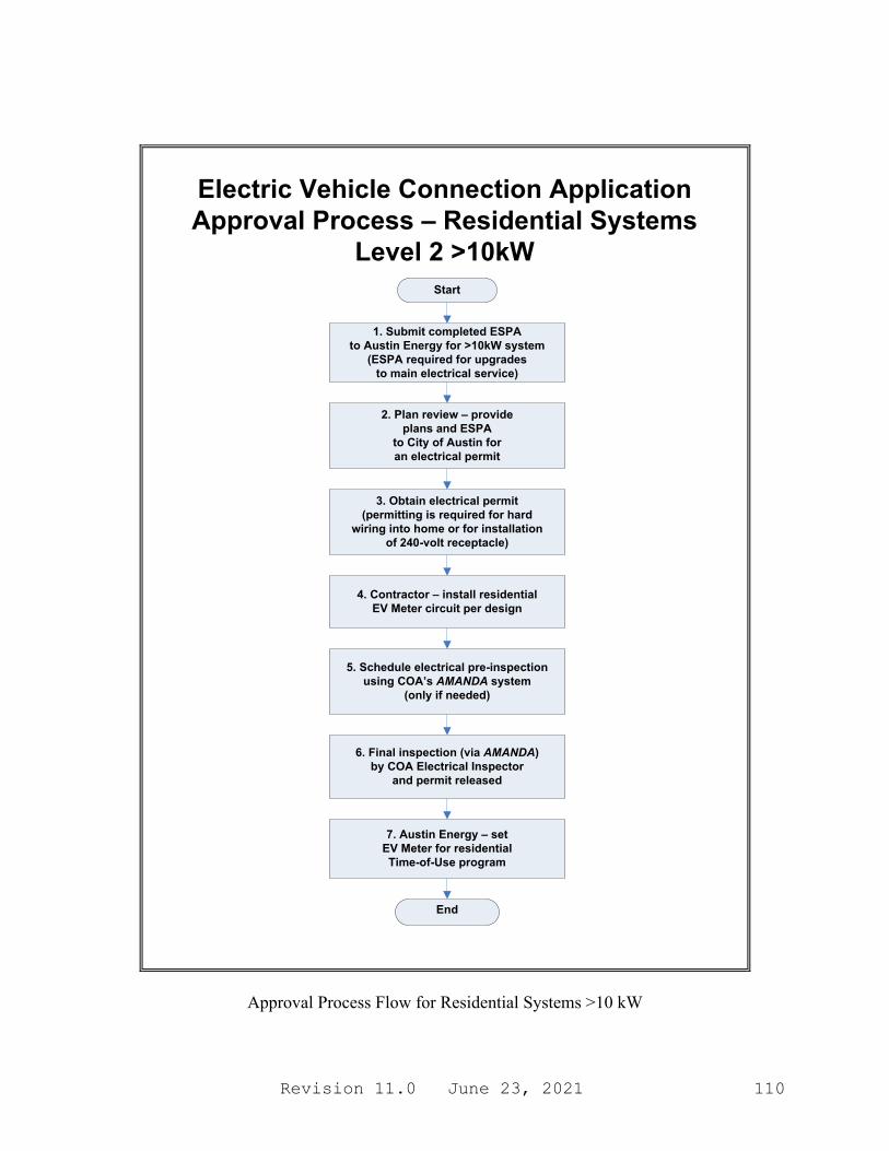
Revision 11.0 June 23, 2021 110
Start
1. Submit completed ESPA to Austin Energy for >10kW system
(ESPA required for upgrades to main electrical service)
2. Plan review – provide plans and ESPA
to City of Austin for an electrical permit
4. Contractor – install residential EV Meter circuit per design
Electric Vehicle Connection Application Approval Process – Residential Systems
Level 2 >10kW
End
5. Schedule electrical pre-inspection using COA’s AMANDA system
(only if needed)
6. Final inspection (via AMANDA) by COA Electrical Inspector
and permit released
7. Austin Energy – set EV Meter for residential Time-of-Use program
3. Obtain electrical permit (permitting is required for hard
wiring into home or for installation of 240-volt receptacle)
Approval Process Flow for Residential Systems >10 kW

Revision 11.0 June 23, 2021 111
5. General System Layouts and Technical Requirements This section reviews general system layouts and components for simple Residential EV Systems. Figure G-1 represents a simplified diagram illustrating the key requirements for typical EV systems less than 10 kW.
AE Grid
M
1. ServiceDisconnect
(Typical)
MainServicePanel
(200-amp)
4. Wall Receptacle
Existing Customer System
Residential EV System Configuration 1 – Level 1 or Level 2 < 10kW
2. Overcurrent protection
Utility XFMR
BillingMeter
5. EVSE/Charging Station
6. J1772 Electrical
Plug/Connector
Figure G-1: Simplified Diagram for Level 1 and Level 2 (<10 kW) for “typical” EV System (with Time of Use Meter)
Customer Owned Equipment
M
7. EV/Charger (AC to DC
Conversion)
Typical 120 volt, 16 amps, 1.9 kW SystemTypical 240 volt, 16 amps, 4.0 kW SystemTypical 240 volt, 32 amps, 8.0 kW System
3. TOU EV Meter
The charging station in Configuration 1 refers to a standardized cord that is provided with the EV. The Level 2 EVSE could also be directly hardwired, bypassing the receptacle.
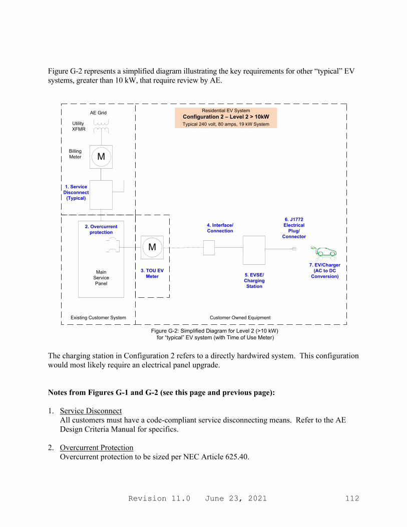
Revision 11.0 June 23, 2021 112
Figure G-2 represents a simplified diagram illustrating the key requirements for other “typical” EV systems, greater than 10 kW, that require review by AE.
AE Grid
M
MainServicePanel
4. Interface/Connection
Existing Customer System
Residential EV System Configuration 2 – Level 2 > 10kW
Utility XFMR
BillingMeter
5. EVSE/Charging Station
Figure G-2: Simplified Diagram for Level 2 (>10 kW) for “typical” EV system (with Time of Use Meter)
M
3. TOU EV Meter
Customer Owned Equipment
Typical 240 volt, 80 amps, 19 kW System
6. J1772 Electrical
Plug/Connector
7. EV/Charger (AC to DC
Conversion)
1. ServiceDisconnect
(Typical)
2. Overcurrent protection
The charging station in Configuration 2 refers to a directly hardwired system. This configuration would most likely require an electrical panel upgrade. Notes from Figures G-1 and G-2 (see this page and previous page): 1. Service Disconnect
All customers must have a code-compliant service disconnecting means. Refer to the AE Design Criteria Manual for specifics.
2. Overcurrent Protection
Overcurrent protection to be sized per NEC Article 625.40.
Revision 11.0 June 23, 2021 113
3. EV Meter (to be on Time of Use rate) a. Installations
i. Contact AE Complex Metering: (512) 505-7045 or EV/ET staff (512) 482-5376.
ii. Refer to Figures G-1 and G-2 for examples of simplified EV installations. Contact AE Complex Metering for any clarification. a) Note: The EV Meter shall be grouped with billing meter and disconnects. b) Facilities with <200 amps current would typically use a self-contained
meter. c) Facilities with >200 amps current would typically use an instrument rated
meter. d) Final determination of meter type and configuration shall be made by the
AE Metering group. iii. Refer to the AE website for detailed meter socket, meter hub, and other related
equipment. iv. http://www.austinenergy.com
• Select the “Contractors” tab • Select the “Electric Service Design & Planning” tab • See “Austin Energy Design Criteria Manual”
4. Receptacle/Interface/Connection
The interface between the EVSE and utility power will generally be a plug and receptacle. A receptacle (120-volt or 240-volt rated in the case of Figure G-1) or a hardwired 240-volt connection (in the case of Figure G-2) shall be provided for the customer’s service connection to the EV system. EVSE connection to comply to NEC Article 625.44. Disconnecting means rated 60 amps or more to comply with NEC Article 625.42.
5. EVSE/Charging Station
Charging station to comply with IEEE 1547 and P2030.1 safety standards. The EVSE is a safety device that allows electricity to flow. Safety is enhanced by enabling two-way communications between the charging station and the EV and by safely delivering and managing electrical energy between an electrical source and an electric vehicle. The EVSE consists of the J1772 connector, cord, and interface to utility power.
6. Electrical Plug
All vehicles produced by automakers in the United States will conform to a single design, known as the J1772 Standard.
7. EV/Charger
Power is delivered to the EV’s onboard battery through the EV inlet port to the charger. The charger converts Alternating Current (AC) from the home to the Direct Current (DC) required to charge the battery in the vehicle. The charger and EV inlet port are considered part of the EV.
Revision 11.0 June 23, 2021 114
End of Interconnection Guide


![Interconnection Works Agreement...Interconnection Works Agreement [Customer] 2 CONTENTS 1. Interpretation 8 1.1 Definitions 8 1.2 Interpretation 15 1.3 No right to transfer electricity](https://img.pdfslide.us/doc/110x75/60ce2eafef59f47e2638e569/interconnection-works-agreement-interconnection-works-agreement-customer-2.jpg)