Embed Size (px)
Citation preview
DISTRIBUTION SYSTEMDESIGN PRACTICE MANUAL
July 2021
1
FAIRFAX WATER
DISTRIBUTION SYSTEM DESIGN PRACTICE MANUALTABLE OF CONTENTSSECTION 1.00 INTRODUCTION ................................................................................... 3
1.01 GLOSSARY OF TERMS ........................................................................................................................ 31.011 Definitions ................................................................................................................................. 31.012 Abbreviations ............................................................................................................................. 3
1.02 PURPOSE ........................................................................................................................................... 41.03 HISTORY ........................................................................................................................................... 41.04 COST RESPONSIBILITY ....................................................................................................................... 51.05 REFERENCES ..................................................................................................................................... 51.06 CONTACT INFORMATION .................................................................................................................... 5
SECTION 2.00 PLAN REVIEW AND APPROVAL ...................................................... 62.01 PLAN REVIEW PROCESS ..................................................................................................................... 6
2.011 Conceptual Plans ....................................................................................................................... 62.012 Construction Plans ..................................................................................................................... 72.013 Special Plans ............................................................................................................................. 72.014 Final Plan Approval and Release for Construction ............................................................................ 82.015 Revisions ........................................................................................................................................... 8
2.02 SUBMISSION REQUIREMENTS ............................................................................................................. 92.021 Conceptual Plan Submissions (Recommended) .................................................................................. 92.022 Construction Plans, Fire Line Plans, Modified Processing Plans, and Revisions (MinimumSubmission Requirements) .......................................................................................................................... 9
2.03 EASEMENTS ..................................................................................................................................... 112.031 Plat Review and Recordation .................................................................................................... 112.032 Plat and Easement Specifications ............................................................................................. 11
2.04 OFFSITE WATER MAINS ................................................................................................................... 122.041 Reimbursement Policy .............................................................................................................. 12
SECTION 3.00 WATER SYSTEM DESIGN ................................................................ 143.01 WATER SUPPLY, PRESSURE AND CAPACITY ...................................................................................... 143.02 FIRE FLOWS .................................................................................................................................... 143.03 WATER MAIN SIZE .......................................................................................................................... 143.04 MATERIAL....................................................................................................................................... 143.05 DEPTH OF COVER ............................................................................................................................ 153.06 WATER SYSTEM LAYOUT ................................................................................................................. 153.07 VALVES .......................................................................................................................................... 153.08 FIRE HYDRANTS .............................................................................................................................. 163.09 UTILITY CLEARANCES ..................................................................................................................... 16
3.091 Sanitary Sewers........................................................................................................................ 163.092 Storm Sewers ........................................................................................................................... 173.093 Gas Mains................................................................................................................................ 173.094 Other ....................................................................................................................................... 17
3.10 THRUST RESTRAINT ......................................................................................................................... 173.11 CASING PIPE .................................................................................................................................... 173.12 WET TAPS ....................................................................................................................................... 183.13 CORROSION CONTROL ..................................................................................................................... 183.14 CROSS-CONNECTIONS ...................................................................................................................... 18
2
3.15 DISTRIBUTION SYSTEM RELOCATIONS ................................................................................................. 183.16 TRANSMISSION MAIN RELOCATIONS .................................................................................................... 19
SECTION 4.00 METERS, SERVICES AND PRIVATE FIRELINES ......................... 204.01 METER LOCATIONS.......................................................................................................................... 20
4.011 General .................................................................................................................................... 204.012 Detached Single-Family Units .................................................................................................. 204.013 Attached and/or Townhouse Units ............................................................................................ 204.014 Large Meter Installations ......................................................................................................... 204.015 Submeters ................................................................................................................................ 20
4.02 SIZING OF THE SERVICE LINE AND METER ........................................................................................ 214.03 FIRE LINES ...................................................................................................................................... 21
SECTION 5.00 PRE-CONSTRUCTION ...................................................................... 225.01 CONTRACTOR APPROVAL................................................................................................................. 225.02 PRE-CONSTRUCTION CHECKLIST ...................................................................................................... 22

3
SECTION 1.00 INTRODUCTION
1.01 Glossary of Terms
1.011 Definitions
Board of Directors – The Board of Directors of Fairfax Water
Conceptual Plans – Plans that generally characterize the planned development of the subject lotincluding, but not limited to; Conceptual Development Plans (CDPs), GeneralizedDevelopment Plans (GDPs), Final Development Plans (FDPs), and Preliminary Plans (PPs)
Construction – The Construction Department of Fairfax Water
Construction Plans – Plans allowing construction after approval and permitting including, butnot limited to; Site Plans (SP), Subdivision Plans (SD), Minor Site Plans (MSP), PublicImprovement Plans (PI)
Director – Director of Fairfax Water’s Planning & Engineering Division
Developer – The entity that is submitting a Plan for Fairfax Water approval.
Engineer – The Virginia-Licensed Professional Engineer responsible for preparing the projectplans and specifications
Fire Line – A privately owned and maintained line connected to a Fairfax Water main oftensupporting a building’s internal fire suppression system
General Manager – The General Manager of Fairfax Water
Plan Control –Jurisdiction that routes Plans to Fairfax Water
Planning – Fairfax Water Planning Department
Plans or Site Plans – The detailed engineering drawings of the proposed uses andimprovements of the subject lot, site, subdivision, public improvement, or other plan reflectingthe design and specifications for the water system
1.012 Abbreviations
ANSI – American National Standards Institute
ASTM – American Society for Testing and Materials
AWWA – American Water Works Association
CL – Class
DIP – Ductile Iron Pipe
4
FW – Fairfax Water
GDP – Generalized Development Plan
gpm – gallons per minute
HGL – Hydraulic Grade Line
PFM – Fairfax County Public Facilities Manual
psi – pounds per square inch
VDH – Virginia Department of Health
ACP – Asbestos Cement Pipe
PCCP – Prestressed Concrete Cylinder Pipe
1.02 Purpose
The Fairfax Water (FW) Design Practice Manual establishes the technical requirementsfor design of distribution-sized water mains (12” and smaller) to be owned, operated andmaintained by FW; and provides engineers preparing Conceptual and Construction Plans with aset of guidelines to ensure conformance with FW’s design principles. Although the goal of thismanual is to be comprehensive, it is understood that a unique situation may arise requiring amodification of FW’s standard design. Final approval of any design, including variances fromand exceptions to these guidelines when deemed appropriate, is ultimately at the direction anddiscretion of Fairfax Water. This manual is a supplemental reference, to be used in conjunctionwith the Virginia Department of Health Waterworks Regulations, the Fairfax County PublicFacilities Manual (PFM) and FW’s Rules and Regulations Governing the Furnishing of WaterService and is not intended to supersede any of these documents.
1.03 History
Fairfax Water was created by the Board of Supervisors in 1957 for the purpose ofacquiring, constructing, operating and maintaining an integrated water system for supplyingand distributing water. As a separate agency from the county government and governed by aBoard of Directors appointed by the Board of Supervisors, FW is financially separate from thecounty and set-up to operate as a true enterprise fund where water system revenues from thesale of water, not taxes, support daily operations, infrastructure reinvestment and systemimprovements. By 1967, FW had accomplished its primary goal of integrating severaldisparate water systems and the focus shifted to maintaining a reliable water supply anddistributing safe, clean water to its customers. In the years following, the expansion of FW’sdistribution system has been largely attributed to the construction of residential and commercialdevelopments throughout the county. The water main installed as part this developmentprocess is ultimately owned and maintained by FW and becomes a critical component in thesupply of water for domestic and fire protection purposes to all customers.
5
1.04 Cost Responsibility
Fairfax Water has a policy of “growth pays for growth” where Developers andindividual homebuilders alike are required to fund the water facilities necessary to providewater service and fire protection to their property. If FW desires to install a larger size watermain or other facility concurrent with the proposed development – whether onsite or offsite -which are not required for the provision of adequate service to that specific development, FW isresponsible for funding these additional expenditures. The standard practice is to determine theappropriate size water main and configuration for present and future anticipated system needs,while maintaining design and construction efficiency.
1.05 References
Sizing Water Service Lines and Meters, Second Edition, AWWA M22, Current Version(available from AWWA for purchase at www.awwa.org)
Construction Practice Manual, Fairfax Water, Current Version
Fairfax Water Standard Details, Fairfax Water, Current Version
Fairfax Water Approved Products List, Fairfax Water, Current Version
Virginia Department of Health Waterworks Regulations, VAC 590(available at www.vdh.state.va.us)
Public Facilities Manual of Fairfax County, Fairfax County Department of Public Works andEnvironmental Services, Current Version
(available at www.fairfaxcounty.gov )
Rules and Regulations Governing the Furnishing of Water Service, Fairfax Water, CurrentVersion
All Fairfax Water documents referenced above are available at www.fairfaxwater.org
1.06 Contact Information
Refer to the Fairfax Water webpage at www.fairfaxwater.org for current contactinformation.
6
SECTION 2.00 PLAN REVIEW AND APPROVAL
2.01 Plan Review Process
Fairfax Water review and approval is required for all Construction Plans that couldpotentially affect FW facilities, regardless of location or water purveyor. In general, FWformally receives Plans as part of the site and subdivision review process submitted to the localjurisdictions. However, FW review is also required for Plans related to federal or stateinstallations, or for other construction activities affecting a FW main in any other federal, state,city, or county jurisdiction.
Plans can be categorized as either Conceptual Plans or Construction Plans. Those of aconceptual nature, including Preliminary Plans preceding the Site Plans, and DevelopmentPlans accompanying proposed zoning actions, do not require formal approval. However,comments are provided by FW to provide guidance for the Engineer in preparation ofsucceeding Construction Plans.
Construction Plans, which include, Site Plans (SPs), Subdivision Plans (SDs), MinorSite Plans (MSPs), Rough Grading Plans (RGPs), Modified Processing Plans, and Fire LinePlans are detailed construction drawings that must be approved by FW prior to startingconstruction. Appendix A contains a flow chart summarizing the review process for SitePlans/Construction Plans.
Fairfax Water is authorized by the Virginia Department of Health (VDH) under a LocalReview Program and General Construction Permit to review and approve water mainextensions 30 inches in diameter and smaller. This permit allows FW to act as the reviewingagent for Site Plans. All projects that will be served by FW, including state or federal projects,which are normally exempt from city or county site and subdivision review processes, requirereview and approval of Construction Plans by Fairfax Water.
The FW Planning Department coordinates review and approval of all ConstructionPlans and seeks the input from other departments and divisions within the organization asnecessary. For federal or state projects, and those Plans that affect FW, but are not processedthrough local jurisdictions, the procedures described in Sections 2.011 and 2.012 are generallythe same, except that all submittals are made directly to Planning and all comments returneddirectly to the Engineer. The following generally describes the sequence and requirements forprocessing various plan types through Fairfax Water.
2.011 Conceptual Plans
2.0111 Development Plans
Development Plans are associated with a variety of city and county land use actions,such as rezonings, special use permits, special exceptions or proffered condition amendments.Development Plans are transmitted to FW for analysis and comment by the local jurisdictionand comments are provided at this stage to identify significant issues related to water service atthe site. FW’s comments are limited to the level of detail and information provided on theDevelopment Plans. If no water facilities are identified, FW will generally note the location ofexisting facilities and return the Plan without additional comments. A response letter and a
7
copy of the annotated Development Plans (as applicable) are returned to the local jurisdictionfor transmittal to the Engineer.
2.0112 Preliminary Plans
Preliminary Plans are submitted to FW for review and comment only. A PreliminaryPlan is a conceptual development layout that should include the proposed horizontal alignmentof proposed water facilities. It is FW’s goal to identify any issues involving water facilitiesprior to final engineering. The submission process consists of the Engineer submitting Plans toPlan Control. Plans are routed to all reviewing agencies for concurrent review. Fairfax WaterPlanning reviews and returns annotated Plans to Plan Control, which returns the Plans to theEngineer.
2.012 Construction Plans
2.0121 First Submittals
A First Submittal is the first submission of the engineered Construction Plans. ThesePlans shall include all the items specified on the minimum requirements checklist in Section2.022, and are reviewed for conformance with FW’s policies, standards, and specifications.Plans shall include plan and profile view of water mains and fire hydrants and shall be sealedby an Engineer. The standard submission process for the First Submittal is to submit Plans toPlan Control, which distributes the Plans to the appropriate agencies for concurrent review.Upon completion of FW’s review, Planning transmits a copy of the marked-up sheets back toPlan Control, which returns the Plans to the Engineer.
2.0122 Final Submittals
Final Submittals are any submittal after the First Submittal. Fire Marshal approval isprerequisite to FW approval. After Fire Marshal approval, the Engineer forwards a set of FireMarshal-approved Plans to FW. Fairfax Water reviews and either approves or comments onthe Plans. This process continues until FW approval is obtained, at which time the Plans maybe submitted to Plan Control for jurisdiction approval. Please note that changes to the watersystem design at Final Submittal may require additional review and approval by the FireMarshal’s office.
2.013 Special Plans
2.0131 Minor Site Plans
Minor Site Plans are defined by Fairfax County, but generally have no publicimprovements, and only minor modifications to a building or site. The process for MSPsdiffers from regular Site Plans in that the Engineer is responsible for identifying the need todistribute the Plans to FW for review for First and Final Submissions.
2.0132 Rough Grading Plans
A Rough Grading Plan (RGP) allows earthwork to begin before the rest of theinfrastructure and can include the installation of utilities to proceed while full Site Plans arebeing processed. RGPs are subject to the same FW review process as other Construction Plans.
8
Please note that FW and jurisdictional approvals of the RGP are necessary prior tocommencement of any water main construction. Upon approval, two sets of jurisdictionapproved Plans and a copy of the grading permit, stating water main or utility installation areapproved, shall be submitted to FW. RGP approval and construction release by FW allows thecontractor to begin installation of water mains; however, prior to construction the Developermust submit a letter to FW’s Construction Department stating the mains will not be filled,flushed, tested, tapped, sampled, or connected to any active FW line until full Site Planapproval is obtained, and approved Site Plans are transmitted to Fairfax Water. Prior to anyconstruction, all easements must be recorded at Fairfax County’s Office of Land Records, andthe deed book and page numbers of recordation confirmed.
2.0133 Modified Processing Plans
Modified Processing Plans are processed similarly to RGPs; however, ModifiedProcessing Plans receive priority and are reviewed or distributed as expeditiously as possible.
2.0134 Fire Line Plans
Fire line plans and other fire protection modifications to a building or site, includingadditions or relocations of on-site fire hydrants, shall be reviewed and approved by FairfaxWater. Plans shall include plan and profile view of the fire line and shall be sealed by anEngineer. The Engineer shall provide two sets of Plans to FW after Fire Marshal and FWapproval for distribution and construction. Additionally, the Developer shall obtain allnecessary permits from VDOT and the local jurisdiction prior to water main construction.
2.014 Final Plan Approval and Release for Construction
Final Plan approval by the local, state, or federal jurisdiction is required prior toconstruction of any FW water mains. The Developer will forward two complete stamped-approved Plans and one partial Plan set that consist of the approved site or grading plan sheetsshowing the meter and service locations on the property to FW prior to starting construction.Prior to construction release, a final check for consistency between the FW approved Plans andthe jurisdiction stamped drawing is completed. Inconsistencies requiring FW approval will benoted to the Engineer and processed as a FW Plan revision as described below. Uponsatisfactory review, FW Planning staff will distribute the Plans as follows:
1. Technical Services Branch (two full sets) – to update system maps followed bydistribution to Construction.
2. Distribution Maintenance (one set of site/grading plan sheets only) – to assist withlocation and construction of new service lines and meters.
2.015 Revisions
A Revision is any change made to a Plan after jurisdiction approval and may occur atany stage from pre-construction through project completion. Fairfax Water must review andapprove all Revisions to the water main design, as well as any Revisions that may affectexisting or proposed FW facilities. Examples include proposed changes to the storm orsanitary sewer design affecting water main crossings, revisions to proposed grades over a watermain, or changes to street or parking lot alignments. When any Revision is made to a Site Plan,
9
the Engineer is required to submit the revised sheets directly to Planning. All revised items areto be circled in red and must be described and dated in the Plan revision table. Revisionsprocessed at the Construction release stage may result in delays. Any Revision submitted afterFW has accepted the mains shall be processed as a separate FW Plan.
2.02 Submission Requirements
The following sections list required plan elements for Plan review. For ConceptualPlans, the list is advisory; however, providing the required information can better facilitatesubsequent Construction Plan approval. All listed items are minimum requirements for FWreview and approval. Additional information may be required for an individual project. Planand profile views of all proposed water lines are to be provided and may be included onseparate sheets. Standard FW notes must be included, and additional FW construction notesare to be provided as warranted by the design. In addition, all Plans must be sealed by anEngineer.
2.021 Conceptual Plan Submissions (Recommended)
Plan view showing existing water mains and appurtenances
Proposed water mains, and hydrant layout
Size, material, and locations of existing and proposed mains
Proposed meter, fire, and service line locations
2.022 Construction Plans, Fire Line Plans, Modified Processing Plans, and Revisions(Minimum Submission Requirements)
2.0221 Plan View
All utilities within 50 feet of the proposed water main and the point of connection toexisting waterline(s)
Designated isolation valve(s) in the existing water system
Normally closed valves called out
Existing and proposed water mains, valves, fittings, appurtenances and fire lines
Call outs for size, material, fittings, valves and appurtenances of existing and proposedwater mains
Test hole locations and results as required
Proposed meter locations and sizes, except for single family detached dwellingsfronting public streets
Proposed service line size and location, except for single family attached and detacheddwellings fronting public streets
10
Independent stationing for all proposed water mains
Existing and proposed Fairfax Water easements and Deed Book and Page reference ofexisting easements
Plan-specific notes
Casing pipes as required
Construction sequence in instances where disruption of existing domestic or fireprotection service will occur
Corrosion protection measures as necessary
Available Fire Flow on coversheet for Final Submittals (to be completed by FairfaxWater upon receipt of First Submittal)
2.0222 Profile View
Independent Fairfax Water waterline profiles with stationing corresponding to the planfor proposed and existing waterlines
Independent fire line profiles
Hydrant laterals greater than 20 feet or where lateral is crossing another utility
Location, size and type of connection(s) to the existing water system
Call outs for fittings, valves, appurtenances, and utility crossings at appropriate stations
Trenchless crossing details, as required
Call outs for cover over water main (4-feet cover typical)
Utility crossings, including all sanitary laterals and call outs for minimum clearances
Test hole locations
Limits of restrained joint pipe for vertical bends and steep slopes
Profile specific notes
Existing and proposed grades
Water main crossings to be shown on the storm and sanitary profiles
Cross sections and test pit data as may be required by Fairfax Water where grading isproposed over existing water facilities
11
2.0223 Notes and Details
Standard Water Main Construction Notes are to be provided on all Plans. The standardnotes are available on the website at www.fairfaxwater.org. Fairfax Water also has additionalnotes for various development conditions. These notes will be provided to the Engineer withfirst submission review comments, as necessary.
2.03 Easements
Water facilities that will become the property of FW and that do not lie wholly within apublic right-of-way are required to be located within easements dedicated to Fairfax Water.Other special conditions may warrant easements to be dedicated or quitclaimed at the directionof FW to address future or existing needs. All easements and quitclaims shall be submitted toFW for review and shall be recorded by the Developer after FW approval. A copy of therecorded deed shall be submitted to FW prior to construction. In limited circumstances, FWmay authorize construction without recorded easements; however, the water mains cannot befilled, flushed, tested, sampled, or connected to existing mains prior to recordation. Thefollowing sections describe the processing requirements for easements, quitclaim of existingeasements, and plat preparation.
2.031 Plat Review and Recordation
All plats containing FW easements shall be reviewed and approved by FW prior torecordation. The Engineer should submit one PDF, or one hardcopy copy of the easement platfor review prior to recordation. Recordation of any FW easement without requisite review andapproval may result in construction delays if plat corrections are deemed necessary.
Two options for easement plats exist –either an independent water-only easement platmay be prepared, or the water main easements may be incorporated into a combined plat for alleasements on the site. If water-only easement plats are prepared, following FW approval, theplat along with a standard Fairfax Water Easement Agreement can immediately be recorded bythe Developer and Plans can be distributed to the Construction Department. For combinedplats, after FW approval, the plat must be processed through the County Attorney’s office priorto recordation. Easements are not considered complete until the easement plat and agreementhave been recorded at Fairfax County’s Office of Land Records and the deed book and pagenumbers of recordation have been submitted to and confirmed by Fairfax Water. Plats forquitclaims may be processed the same as easements; however, quitclaim agreements require thesignature of the Fairfax Water General Manager prior to recordation. Refer to Appendix B fora flow chart summarizing the easement recordation process.
For offsite easements, FW will not release Plans for construction until the associatedeasements are recorded. Upon recordation of all plats, the Developer is required to provide thedeed book and page number to FW for verification.
2.032 Plat and Easement Specifications
Fairfax Water standard easement agreements shall be used and are available on the FWwebsite at www.fairfaxwater.org. Easement plats are to be drawn on sheets between 8 ½ by 11inches and 18 by 24 inches in size with a 1-inch minimum top, left, and bottom margin, and a
12
½-inch minimum right margin. All Fairfax Water easements are to be called out as FCWAEasements. Fairfax Water easements are normally 15 feet wide. For water mains 16 inches indiameter or larger, a 24-foot easement is required. Fire hydrants are normally located in a 10-foot easement, as are water meters that require easements. Fairfax Water easements are for FWfacilities only and are not to be combined with “ingress/egress” or “utility” easements.
2.04 Offsite Water Mains
Offsite water mains are defined as any main required to be installed beyond the limits ofthe property being developed. The Developer is responsible for design and construction of allrequired water main improvements, both on and offsite. If an offsite water main extension isrequired, Planning will note this with return of the First Submittal. After the Plans have beenapproved by FW, Planning will notify FW’s Design Department to prepare a cost proposaldetailing the conditions and limits of reimbursement for the design and construction of theoffsite water main extension. The proposal will be sent to the Developer as shown on the coversheet of the Plans for signature. To be considered for reimbursement, the proposal must beexecuted by the Developer prior to any water main construction. If construction proceedswithout execution of the proposal, all rights for reimbursement are waived.
If an offsite water main requires an easement, it will be the Developer’s responsibilityto acquire the easement. The Developer must prepare and record the easement agreement andplat after FW approval. Prior to construction, the Developer shall provide FW the deed bookand page number of all recorded easements needed for the project.
The Plans for the offsite water main may be included with the Site Plan, on a separatePlan for the offsite water main only, or as part of a Public Improvement Plan. Fairfax Waterprefers that the water main be included as part of the Site Plan. All offsite water mainextensions become FW projects for the purpose of tracking expenditures and monitoringreimbursements.
In the case where a homeowner wishes to extend a water main to obtain a singleservice, a cost proposal is prepared but with the option of either the homeowner or FWcompleting the design and construction the offsite water main. If the homeowner chooses to dothe work, they will be required to submit a Plan to the local jurisdiction for approval. When thehomeowner chooses to complete the design, they will be responsible for obtaining any requiredeasements, permits, and approvals. If FW is chosen to do the work, the design and constructionwill be handled by FW including obtaining all required permits and approvals. However, if aneasement is required, it will be the responsibility of the homeowner to negotiate and acquire theproper easements, but FW will prepare and record the associated easement plats. Fairfax Waterwill not begin the design of the offsite water main extension until the proposal is signed and allcosts are paid. Additional information regarding the water main extensions process can beobtained from the contacts listed on the FW website.
2.041 Reimbursement Policy
Fairfax Water’s reimbursement of offsite water main installation costs is based on thenumber of service connections associated with the development and future service connectionsto the offsite main. The total reimbursement cannot exceed FW’s estimated cost to design andconstruct the offsite water main extension, details of which are included in the cost proposal.

13
The date that the offsite water main is placed in-service becomes the anniversary date for theproject. Each year thereafter on that date, the Developer will be reimbursed, based on thenumber and size of onsite meter installations the preceding year. Fairfax Water inspectioncosts for the offsite portion of main will be deducted from any eligible reimbursements untilthat obligation is satisfied. Reimbursements are limited to the five-year period following thedate on which the offsite water main was placed in-service. Additional information regardingthe reimbursement process can be obtained from the Water Main Extension Policy on the FWwebsite.

14
SECTION 3.00 WATER SYSTEM DESIGN
3.01 Water Supply, Pressure and Capacity
Water distribution systems shall be designed to supply the projected peak day flowwhile maintaining a residual pressure of at least 35 psi at all points in the subdivision. Thesystem must also be designed to provide fire flows as specified by the local jurisdiction whilemaintaining a minimum residual pressure of 20 psi at all points in the distribution system.
If the maximum working pressure for the site is 80 psi or greater, a pressure-reducingvalve (PRV) will be required consistent with the plumbing code and FW’s rules andregulations. The owner must install the PRV in the building plumbing system to eliminatewater hammer and unnecessary wastage of water.
3.02 Fire Flows
Fire flow requirements are determined by the local jurisdiction and should be providedon all Plans. Planning will perform a fire flow analysis during the first review and provide theavailable fire flow to the Engineer. In the event of insufficient fire flow, FW will providedirection to the Engineer on what improvements are needed to achieve adequate flows.
For sprinklered structures, the Fire Marshal’s Office requires flow information from anexisting hydrant and the minimum hydraulic grade line (HGL) for the area where thedevelopment is located. This information is required as part of the building mechanical plansubmission. Hydrant flow data and minimum HGL information may be obtained from FW’sPlanning department as shown in the contact list.
3.03 Water Main Size
The standard sizes of water main in our distribution system include 4-inch, 6-inch, 8-inch, and 12-inch diameter pipe, with 4-inch mains being the minimum accepted size.Generally, water mains shall be 8 inches in diameter when located in local streets, and 12inches in diameter when located in collector or arterial roadways. Where fire protection is tobe provided or required, the minimum diameter pipe shall be 6 inches. The minimum line sizeused in dead ends, cul-de-sacs, or pipestems beyond the last fire hydrant, when only domesticservice is required is 4 inches. A minimum 4-inch line is also required for pipestems servingmore than two lots, as well as water main extensions less than 300 feet in length servingindividual residential connections. All pipe size requirements are dependent on the ability todeliver adequate flows and pressures.
3.04 Material
All water mains shall be thickness class 52 ductile iron pipe unless otherwise specified.A complete listing of approved products by manufacturer for pipes, valves, fittings, and otheritems can be found at www.fairfaxwater.org.
15
3.05 Depth of Cover
Standard depth of cover for all water main installation is 4 feet. The cover can bereduced to a minimum of 3 feet at utility crossings to avoid excessive overdepth associatedwith going under sewers or other utilities; valves may not be placed in areas of reduced cover.The maximum allowable cover is 7-½ feet. In situations where the cover would exceed 7-½feet, alternate designs that avoid excessive cover shall be investigated. Where a Plan alters thecover on an existing water main, a minimum of 3 feet and a maximum of 7-½ feet shall beprovided. Test holes will be required prior to FW Plan approval to verify final cover over theexisting water main is within these limits. If the proposed cover falls outside these limits, watermain relocation is normally required. Refer to sections 3.15 and 3.16 for additionalinformation on relocations.
3.06 Water System Layout
Water supply systems should be designed to minimize the occurrence of dead-end linesfor water quality and reliability purposes. At the discretion of FW staff, Developers may berequired to close loops or provide stub outs for future system looping, access, extensions and/oradditional supply sources. Easements may be required to accommodate future water maininstallation, or to provide access to FW facilities through adjacent properties. Where dead-endlines are unavoidable, the Engineer should attempt to locate service connections as close to thetermination as possible. A blow-off assembly for line flushing is required on all dead-end lineswhere warranted and feasible.
Waterlines should normally be designed to run within streets and travel ways on theNorth or East side of the street centerline. In streets, waterlines are to be located a minimum of5 feet from the edge of the gutter pan. Additional separation from the gutter pan is preferredsubject to adequate separation from other utilities as well as VDOT location requirements. Thewater main should remain on the same side of the centerline for the entire length of the street.Additional information regarding water main location requirements can be found in Section 9of the PFM.
Where VDOT requires the Developer to perform frontage improvements, futuredisturbance to the improvements should be minimized. The water main design shouldterminate such that future extensions and tie-ins do not disturb the recent VDOT improvements.
Where a deceleration lane exists, the water main generally should not bend to follow thealignment of the turn lane’s gutter pan but should continue along the same alignmentmaintaining 5 feet from the gutter pan before and after the deceleration lane. In townhouse orcommercial developments, the water main is to be centered in a 15-foot easement on one sideof the travel way. The edge of the easement should be contiguous with the edge of the gutterpan and the main should remain on one side of the travel way as in a street. Water mainsshould be aligned, to the extent possible, through drive aisles, and not through parking spacesin lots. Public water mains shall be a minimum of 20 feet from any building.
3.07 Valves
Valving shall be provided to allow for adequate isolation of the water system, and at aminimum, every 1,000 feet or at every intersection whichever is less. For water mains 12
16
inches and less in diameter, resilient seated gate valves shall be utilized. Butterfly valves shallbe used for all mains 16 inches and larger.
Unless otherwise directed, three valves are to be provided at tees, and four valves atcrosses. At a stub out or a temporary termination of a water main, a restrained valve is to belocated beyond the last service connection if applicable, and within 40 feet of the end of theline. Valves are always used to isolate fire hydrants and should be proximate to the hydrant.Where the hydrant comes off a tee, a restrained valve is required on the branch at theconnection to the main. On long hydrant leads, it may be necessary to place a secondrestrained valve within 10 feet of the fire hydrant. Mainline valves are typically not required athydrant tees, unless necessary to meet isolation requirements (approximately every 1,000 feet).Restrained valves shall also be provided on all private fire lines at the connection to the mainand all valves at domestic take offs from fire lines. Valves are to be in either paved or greenareas and should not fall within curb and gutter or sidewalk areas. Valves are not permitted inparking spaces. When valves are called for on the plan view, the water main must be parallel tothe grade at the corresponding station on the profile.
3.08 Fire Hydrants
Hydrants are to be provided per local jurisdiction requirements to meet the coveragerequirements of the Fire Marshal, and at high points and low points in the system on mains 12inches and larger for air release and blow-off purposes. The Engineer should try to satisfy firecoverage requirements and air release/ blow-off requirements simultaneously to minimize thenumber of hydrants. Offset tees shall not be used for air release and blow-off hydrants in mains16 inches and smaller. Fire hydrants are to be placed as close to the main as practical and areto be located upstream of the last service connection on dead-end lines for water qualitypurposes. On residential streets, hydrants should be placed at the lot line between propertiesand are not to be placed in a cul-de-sac. Additional information on hydrant placement can befound in FW’s Standard Details and Section 9 of the PFM.
3.09 Utility Clearances
3.091 Sanitary Sewers
Section 12VAC5-590-1150 of the Virginia Department of Health (VDH) WaterworksRegulations governs sanitary sewer crossings and must be consulted for all requirements. Ingeneral, the minimum horizontal separation between a water main and a sanitary sewer orsewer manhole is 10 feet, measured edge to edge. At crossings of waterlines and sanitarysewer, including sanitary laterals, a minimum vertical clearance of 18 inches is requiredbetween the bottom of the water line and the top of the sewer. If this minimum clearance is notpossible, ductile iron sewer pipe and other provisions as established by VDH are required.Sanitary crossings are to be called out on the water main profile, and water main crossings areto be shown on the sanitary profile. Where minimum clearances cannot be maintained, a fulllength of pipe must be used at the crossing location and centered at the crossing with its jointsequidistant from the sewer line; other provisions must be provided as required by Section12VAC5-590-1150 of the VDH Waterworks Regulations.
17
3.092 Storm Sewers
The minimum horizontal separation between a storm sewer and a waterline is 6 feet,measured edge-to-edge. Where a water main crosses above a storm sewer, a minimumclearance of 6 inches is required. Where the water main crosses below the sewer, 12 inches ofclearance is required. These clearances are to be called out on the water main profile. Thewater main crossings are to be shown on the storm sewer profile.
3.093 Gas Mains
The minimum horizontal separation between water mains and appurtenances includingbut not limited to service lines, meter boxes, valve boxes, and hydrants and gas mains shall be 5feet. A minimum vertical clearance of 12 inches is required when crossing a gas main. Thelarge petroleum product pipeline companies (e.g., Colonial and Columbia) may impose aminimum vertical separation greater than 12 inches, along with concrete pads above theirpipelines. Consult the pipeline companies for additional information when working withintheir right-of-way.
3.094 Other
No other utilities are permitted in waterline easements, although as space constraintswarrant, easements may overlap. When a water main crosses below another utility, water mainvalves shall be placed so as not to conflict with the other utility. In general, this means notlocating any valves in the other utility’s easement. Utility crossings should be designed asclose to ninety degrees as possible. Plan and profiles of all utility crossings of water mainswithin easements shall be submitted to FW for approval prior to construction.
3.10 Thrust Restraint
All tees, bends, plugs, caps, and fire hydrants are to be restrained against movement inaccordance with FW Standard Details, available at www.fairfaxwater.org. Thrust blocks are tobe constructed in accordance with FW’s Standard Details and must rest against undisturbedsoil. Horizontal bends are not to be placed above a storm or sanitary sewer, or in such amanner as to cause the blocking for the bend (or tee) to be in disturbed earth. Thrust blocking,restraining glands, or restrained joint pipe may be required at the discretion of the FW inspectorin the field even if not reflected in the approved Plan. All fire hydrant, fire line, and stub-outvalves shall be restrained. Swivel fittings are optional in place of restraining for fire hydrantvalve installations. These valves shall be identified as restrained on both the plan and profileview. Hydrants, which are on a dead-end line with a ninety-degree bend instead of a tee, shallhave a restrained valve located prior to the bend. Restrained joint pipe shall be used before andafter vertical bends per FW Standard Details.
3.11 Casing Pipe
All trenchless crossings require pipe to be installed within a casing. Casings are to beshown on the plan and profiles, and the size of the casing is determined by the size of thecarrier pipe. Refer to FW Standard Details when specifying the size of the casing pipe. Due tostate regulations, trenchless crossings should have a minimum 24” vertical separation whencrossing water or other utilities.

18
3.12 Wet Taps
Wet taps connections are generally preferred to avoid interruption of existing waterservice, except when there is inadequate isolation valving on existing mains. Size-on-size wettaps are permitted on ductile iron pipe (DIP) 12 inches and smaller in diameter. Taps onprestressed concrete cylinder pipe (PCCP) are limited to half the diameter of the pipe beingtapped. Taps on cast iron pipe (CIP) and asbestos cement (ACP) pipe shall be at least one sizesmaller than the diameter of the pipe being tapped. Tapping sleeves are required on all taps 12inches and smaller, while saddles are permitted on taps 16 inches and larger. When saddles areused, the proposed connecting line is limited to half the diameter of the pipe being tapped.
3.13 Corrosion Control
Corrosion control measures are based upon field conditions, pipe size, and type ofinstallation. Generally, zinc coated pipe and polyethylene encasement are sufficient; however,additional measures may be required for water mains crossing pipelines with impressed currentcathodic protection and pipes in trenchless crossings. Examples of pipelines that typically haveimpressed current cathodic protection are larger diameter gas/petroleum pipelines owned byColonial, Transco, or Columbia Gas. Corrosion may also present a problem in areas with whatare described as “hot” soils or in areas where stray electrical current is present (e.g., nearMetrorail track). Specific requirements in these areas are handled on a case-by-case basis.
Polyethylene encasement shall be in accordance with ANSI/AWWA C105/A21.5 –American National Standard for Polyethylene Encasement for Ductile Iron Pipe Systems, andthe FW Standard Trench Detail. The flat tube form shall be used with minimum width basedon nominal pipe diameter in accordance with ANSI/ AWWA C105/A21.5.
3.14 Cross-Connections
An approved backflow prevention device is required on all residential, commercial,industrial, or institutional use that handles hazardous materials or has potential crossconnections with other plumbing systems. The installation, inspection and testing shall be inaccordance with all applicable state or local codes and standards.
Fairfax Water reserves the right to require additional backflow prevention above andbeyond state and local requirements on any service line if it is determined that a potentiallyhazardous condition exists that could contaminate the distribution system. Please refer to theFW Cross Connection Control and Backflow Prevention Program Manual online for moreinformation.
3.15 Distribution System Relocations
The Developer is responsible for any relocation or removal of water mains andappurtenances (including hydrants) due to the development of the site. Abandoned water mainsthat remain in the ground shall be plugged or capped in accordance with FW’s standard detailsand specifications. Hydrants that require relocation shall only be reused at the direction ofFW’s inspector. In most cases, the hydrant to be relocated will require replacement due to itsage or excessive maintenance requirements. Service lines which will no longer be used shall be
19
removed and disconnected at the water main by the Developer, and the corporation stop shut-off and capped, or removed and plugged as directed by a FW inspector.
3.16 Transmission Main Relocations
Water mains larger than 16 inches in diameter constitute the backbone of the FWtransmission system. Their continuous operation is necessary to ensure adequate flow andpressure throughout the system for the provision of domestic service and fire protection,therefore all proposed relocations of water mains larger than 16 inches in diameter initiated byprivate development activity must be requested in writing and approved by the Fairfax WaterBoard of Directors.
The Developer shall submit a letter to the attention of the Director of Planning andEngineering, requesting permission to relocate the existing transmission main. Submission ofsuch a request, if necessary, is recommended as soon as possible to avoid subsequent projectdelays or rework. Relocation of the transmission main, if approved, will be at the Developer’sexpense. For all approved transmission relocations, FW requires the Developer to enter into awritten agreement that obligates the Developer to complete all work in accordance with thePlans approved by Fairfax Water.
20
SECTION 4.00 METERS, SERVICES AND PRIVATE FIRELINES
4.01 Meter Locations
4.011 General
Fairfax Water shall determine meter locations and special metering requirements at Planreview. Fairfax Water will maintain the service line from the connection at the water main upto and including the meter for single-family residential properties. For this reason, watermeters are to be located as close to the main as possible. Note that one continuous piece ofcopper is required between the main and the meter, which limits the length of the service linefrom the main in the street to the meter to 50 feet. For multi-family and non-residential meters,FW will maintain that portion of the service line within the easement as well as the meter. Inthe case of domestic services connected directly to private fire lines, FW maintains no portionof the service line, and only the meter itself.
Water meters are to be located at least 5 feet from sanitary sewer laterals and stormsewer inlets. A water meter may be located above a storm sewer only if the sewer has aminimum of 3 feet of cover.
4.012 Detached Single-Family Units
Water meter locations are typically not shown on Plans for single-family detacheddevelopments fronting public streets. These locations will be established by FW at the time ofconstruction. Water meters on pipestems or private streets require FW easements, and need tobe shown on the Plans. In the case of private streets, meters are to be set at the property line orbehind the sidewalk within the FW easement. In pipestems and other private streets withoutcurb and gutter, meters are to be located on the property they are serving in a green area asclose to the main as possible, beyond the ditch or shoulder in an easement. A 10-foot easementmust encompass the service line and meter.
4.013 Attached and/or Townhouse Units
For townhouse developments, water meters normally are installed in the utility strip.Where no utility strip is provided, meters should go behind the sidewalk within a FW easement.Meters should be located on the property line in pairs where possible.
4.014 Large Meter Installations
All water meters 3 inches and greater are to be installed inside a building within aheated area with a remote readout on the building’s outside wall. All smaller meters shallnormally be installed outside in a grassy space, soil, or vegetative area without obstructions in aFW approved crock.
4.015 Submeters
For certain applications, it may be cost effective to install a submeter (sewer subtractionmeter) for purchased water that will not be discharged into the public sewer system, such as forirrigation. The submeter, which is installed downstream of the main meter is also read by FW,
21
however, FW will not maintain the submeter. The submeter should be located as close to themain meter as possible, but in a separate crock.
Submeters may also be used for commercial or mixed-use developments to measureconsumption of individual tenants when the building has only a single billing meter.
4.02 Sizing of the Service Line and Meter
For single-family residential units, the service line between the main and the meter shallbe 1-inch type K copper, and the meter shall be 5/8-inches. For other development types,sizing of the service lines and meters will be the Engineer’s responsibility and shall be basedupon the fixture loading imposed by the building in accordance with AWWA Manual No.M22, Sizing Water Service Lines and Meters. It is the Engineer’s responsibility to ensure thisis accomplished and the size is included on the site plans. It is advantageous in non-residentialconstruction to use the smallest meter that will accommodate expected demands, asAvailability Fees are based upon meter size and costs can be significant.
Except in the case of a sprinklered building, every meter shall have an independentservice line connecting to a FW main. For sprinklered buildings, domestic service lines areconnected to the private fire line outside the building, rather than a separate connection to thepublic main. A minimum 3-inch gate valve on the domestic line at the point of connection tothe fire line must be provided for isolation purposes. Domestic service lines may be reducedbeyond the isolation valve if needed. If the meter and service are located on the property that itserves, no easements are required. See FW Standard Details for meter and service lineconfiguration details.
4.03 Fire Lines
Private fire lines are generally required when a building has an internal fire protectionsystem. Where private fire lines are installed, FW requires a restrained valve to be installed atthe point where the fire line connects to the FW water main, beyond which the fire line isprivately owned and maintained. This is to be clearly labeled as “private fire line” on thePlans. An independent profile of the fire line is to be provided.
22
SECTION 5.00 PRE-CONSTRUCTION
5.01 Contractor ApprovalExperience in the installation of ductile iron pipe is required. The Contractor shall
thoroughly familiarize himself with all specific manufacturing and installation requirementsof the pipe material shown on the approved Construction Plans.
Upon request, the Contractor shall submit the pipe superintendent's and pipe installationcrew’s experience in installing the pipe material and joint types to be used. Give project titles,pipe diameter and length, locations, reference contacts, addresses, and telephone numbers.When requested, information should be sent to:
Chief Construction EngineerFairfax Water
8560 Arlington BoulevardFairfax, VA 22031FAX 703-289-6351
5.02 Pre-Construction Checklist
Prior to beginning the construction of water mains, the Construction Departmentrequires the following:
1. Hard copies of the Plans approved by the state/local jurisdiction
2. Cut sheets with Virginia P.E. or L.S. seal and signature
3. 72-hour notice prior to beginning work
4. Deed Book and Page number of recorded easements
5. For Rough Grading Plans and Modified Processing Plans:
a. A letter from the Developer stating that the water mains will not be filled, tested,tapped, flushed, or sampled until Construction Plans are received
b. A copy of the Rough Grading Permit with approval for water main installation
6. Executed Offsite Proposal (if applicable)

23
APPENDIX AFAIRFAX WATER SITE PLAN REVIEW PROCESS
24
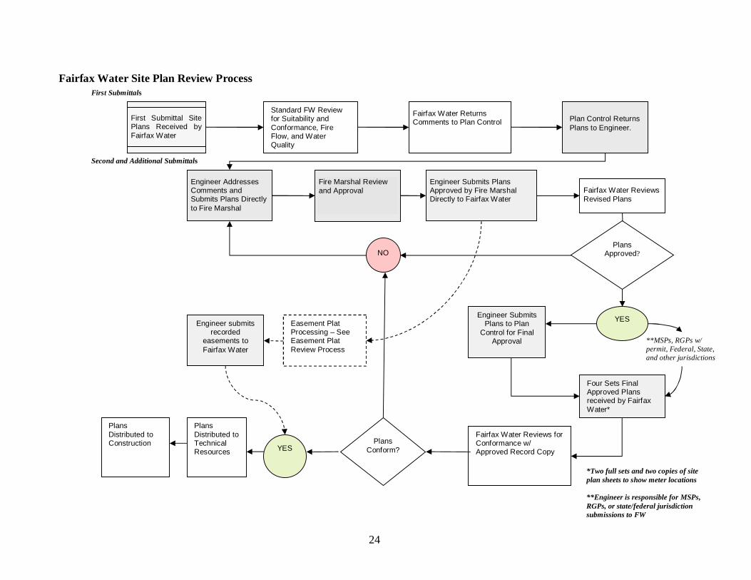
Fairfax Water Site Plan Review Process
Plan Control ReturnsPlans to Engineer.
Standard FW Reviewfor Suitability andConformance, FireFlow, and WaterQuality
Engineer Submits PlansApproved by Fire MarshalDirectly to Fairfax Water
Fairfax Water ReviewsRevised Plans
First Submittal SitePlans Received byFairfax Water
Fairfax Water ReturnsComments to Plan Control
**MSPs, RGPs w/permit, Federal, State,and other jurisdictions
Engineer SubmitsPlans to Plan
Control for FinalApproval
PlansApproved?NO
YES
Fairfax Water Reviews forConformance w/Approved Record Copy
Four Sets FinalApproved Plansreceived by FairfaxWater*
PlansDistributed toTechnicalResources
PlansConform?YES
Easement PlatProcessing – SeeEasement PlatReview Process
PlansDistributed toConstruction
Engineer AddressesComments andSubmits Plans Directlyto Fire Marshal
Fire Marshal Reviewand Approval
Second and Additional Submittals
First Submittals
Engineer submitsrecorded
easements toFairfax Water
*Two full sets and two copies of siteplan sheets to show meter locations
**Engineer is responsible for MSPs,RGPs, or state/federal jurisdictionsubmissions to FW

25
APPENDIX BFAIRFAX WATER EASEMENT PLAT REVIEW PROCESS
26
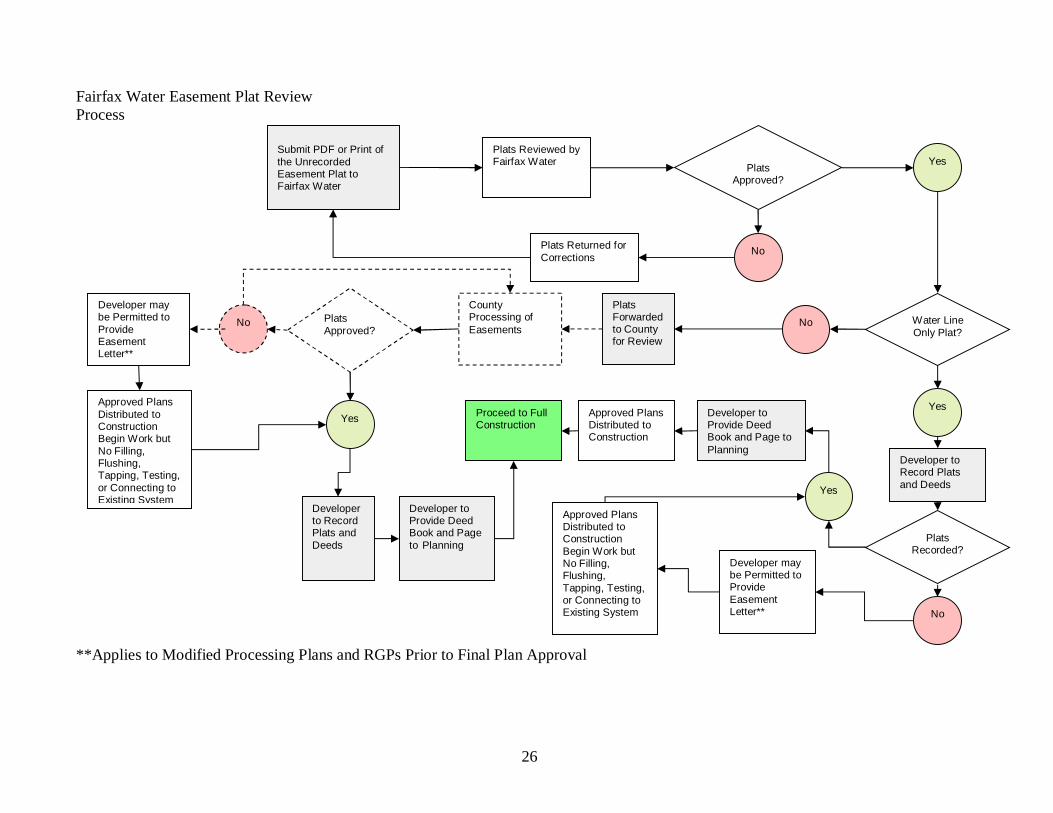
Fairfax Water Easement Plat ReviewProcess
**Applies to Modified Processing Plans and RGPs Prior to Final Plan Approval
Submit PDF or Print ofthe UnrecordedEasement Plat toFairfax Water
Plats Reviewed byFairfax Water Plats
Approved?
Water LineOnly Plat?
Plats Returned forCorrections
PlatsForwardedto Countyfor Review
No
Yes
No
Yes
Developer toRecord Platsand Deeds
Developer toProvide DeedBook and Page toPlanning
Approved PlansDistributed toConstruction
CountyProcessing ofEasements
Developer maybe Permitted toProvideEasementLetter**
Proceed to FullConstruction
Approved PlansDistributed toConstructionBegin Work butNo Filling,Flushing,Tapping, Testing,or Connecting toExisting System
Developer toProvide DeedBook and Pageto Planning
Developerto RecordPlats andDeeds
PlatsApproved?
No
Yes
PlatsRecorded?
Yes
No
Approved PlansDistributed toConstructionBegin Work butNo Filling,Flushing,Tapping, Testing,or Connecting toExisting System
Developer maybe Permitted toProvideEasementLetter**

26