Embed Size (px)
Citation preview

Distribution Substation Manual
(DSM)
Section 2 – HV Network Arrangements
March 2007

Document release information
Client Western Power
Project name Distribution Substation Manual
Document number 2
Document title HV Network Arrangements
Revision status 3rd Edition
Document prepared by:
Western Power ABN 18540492861
85 Prinsep Road, Jandakot
Revision History Edition/Revision Number
Issue Date Description Endorsed By
Approved By
First Edition June 1997 Distribution Substations Manual (DSM) issued
NA NA
Second Edition February 2002 Revised from First Edition Ed Wilcox Robert Rogerson
Third Edition March 2007 DSM split into 10 Sections – Introduction and Sections 1 to 9
Sandeep Magan
Robert Rogerson
© Copyright of Western Power Any use of this material except in accordance with a written agreement with Western Power is prohibited. Third edition January 2007 Apart from any fair dealing for the purposes of study, research, criticism or review, as permitted under the Copyright Act, no part may be reproduced by any process without written permission. Inquiries should be made to Distribution Standards and Policy Manager, Asset Management Division, Western Power, 85 Prinsep Road, Jandakot 6164

Distribution Substation Manual HV Network Arrangements Tuesday, 13 March 2007
Table of contents
2) HV Network Arrangements 1
2.1 Design Philosophies 2 2.1.1 General 2 2.1.2 22kV Philosophy 2 2.1.3 11kV Philosophy 3 2.1.4 6.6kV Philosophy 4 2.1.5 33kV Philosophy 4
2.2 Design Notes 5 2.3 Drawings 8


Section 2 - HV Network Arrangements
2) HV Network Arrangements Index of Drawings
Drawing Number Drawing Title
DSM-2-00 Legend
6.6kV Overhead Supply
DSM-2-01 District & Sole Use Substations - Typical Metro
DSM-2-02 Customer Owned Substations - Typical Metro
6.6kV Underground Supply
DSM-2-03 District And Sole Use Substations - Typical Metro
DSM-2-04 Customer Owned Substations - Typical Metro
11kV Overhead Supply
DSM-2-05 District And Sole Use Substations - Typical Metro
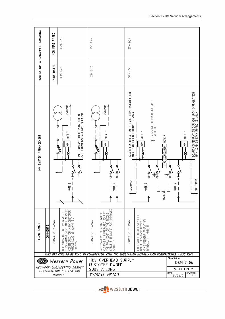
DSM-2-06 Customer Owned Substations - Typical Metro
11kV Underground Supply
DSM-2-07 District And Sole Use Substations - Typical Metro
DSM-2-08 Customer Owned Substations - Typical Metro
22kV Overhead Supply
DSM-2-09 District And Sole Use Substations - Typical Metro
DSM-2-10 District And Sole Use Substations - Typical Rural
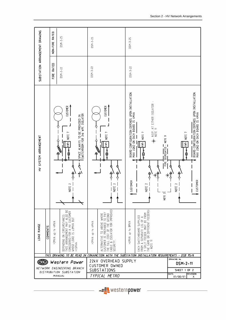
DSM-2-11 Customer Owned Substations - Typical Metro
DSM-2-12 Customer Owned Substations - Typical Rural
22kV Underground Supply
DSM-2-13 District And Sole Use Substations - Typical Metro And Rural
DSM-2-14 Customer Owned Substations - Typical Metro And Rural
33kV Overhead Supply

Distribution Substation Manual Section 2 - HV Network Arrangements
Drawing Number Drawing Title
DSM-2-15 District And Sole Use Substations - Typical Rural
DSM-2-16 Customer Owned Substations - Typical Rural
2.1 Design Philosophies
The HV network arrangements shown in this section of the Manual are based on the following design philosophies:
2.1.1 General
For all voltages the nominal maximum feeder load is taken as 390A for a first contingency outage. The nominal maximum load under normal operating conditions is 260A. Note that other feeder loads (and hence HV network arrangements) may be possible if alternative designs are used - eg duplicate feeder cables. However, these are not reflected in the Manual.
2.1.2 22kV Philosophy
The 22kV HV network arrangement for shared feeders is based on the ‘Y’ configuration specified in Report ESD 65/93. The maximum permissible load on each leg of the ‘Y’ is 130A or 5MVA. Arrangements are based on limiting the maximum discrete load on one leg of the ‘Y’ for a shared feeder to 4MVA, leaving 1MVA available for other loads. In practice, the designer will need to review specific situations and vary the load ranges for a particular arrangement taking into account existing and potential loads. Dedicated feeders can be loaded to 390A or 15MVA. This philosophy results in the following arrangements:
I. Discrete loads up to 4MVA - the load can be supplied from one leg of a shared ‘Y’ configured feeder.
II. Discrete loads above 4MVA up to 8MVA - the load must be evenly split across two switchboards (with a maximum of 4MVA per switchboard). Each switchboard can be supplied from one leg of a shared ‘Y’ configured feeder, with a normally open point between the switchboards (the two legs can be from the same or different feeders). Note that where this load is to be supplied from a feeder that is not in the ‘Y’ configuration, it may be acceptable to operate with the normally

Section 2 - HV Network Arrangements
open point closed until such time as the ‘Y’ configuration is implemented on the feeder.
III. Discrete loads above 8MVA up to 15MVA - the load must be supplied from a dedicated feeder. Such loads will have limited backup unless a second dedicated feeder is provided.
IV. Discrete loads above 15MVA - such loads must be assessed on an individual basis. It is generally preferable that they be supplied from the transmission network rather than the distribution network.
2.1.3 11kV Philosophy
The 11kV HV network arrangements for shared feeders are not based on ‘Y’ configuration. The maximum permissible loading on a shared feeder is 260A or 5MVA. Arrangements are based on limiting the maximum discrete load on a feeder to 4MVA, leaving 1MVA available for other loads. In practice, the designer will need to review specific situations and vary the load ranges for a particular arrangement taking into account existing and potential loads. This philosophy results in the following arrangements:
I. Discrete loads up to 4MVA - the load can be supplied from a single shared feeder.
II. Discrete loads above 4MVA up to 8MVA - the load must be evenly split across two switchboards (with a maximum of 4MVA per switchboard). Each switchboard can be supplied from a separate shared feeder, with a normally open point between the switchboards (ie, two feeders operating radially). Note that discrete loads above 4MVA up to 7.5MVA could also be supplied from a dedicated feeder, however, this arrangement is not shown.
III. Discrete loads above 8MVA - such loads must be assessed on an individual basis.
Note that the arrangements shown for 11kV are suitable for future conversion to 22kV based on the ‘Y’ configuration.

Distribution Substation Manual Section 2 - HV Network Arrangements
2.1.4 6.6kV Philosophy
The 6.6 kV HV network arrangements for shared feeders are not based on the ‘Y’ configuration. The maximum permissible loading on a shared feeder is 260A or 3MVA. Arrangements are based on limiting the maximum discrete load on a feeder to 2MVA, leaving 1MVA available for other loads. In practice, the designer will need to review specific situations and vary the load ranges for a particular arrangement taking into account existing and potential loads. This philosophy results in the following arrangements:
I. Discrete loads up to 2MVA - the load can be supplied from a single shared feeder.
II. Discrete loads above 2MVA up to 4MVA - the load must be evenly split across two switchboards (with a maximum of 2MVA per switchboard). Each switchboard can be supplied from a separate shared feeder, with a normally open point between the switchboards (ie, two feeders operating radially). Note that discrete loads above 2MVA up to 4.5MVA could also be supplied from a dedicated feeder, however, this arrangement is not shown.
III. Discrete loads above 4MVA - such loads must be assessed on an individual basis.
Note that the arrangements shown for 6.6kV are suitable for future conversion to 22kV based on the ‘Y’ configuration.
2.1.5 33kV Philosophy
For 33kV, the same philosophy and loading levels have been used as for 22kV.

Section 2 - HV Network Arrangements
2.2 Design Notes
The following design notes are referenced on the HV network arrangement drawings:
Note 1 HV network arrangements off the existing HV overhead network within the metro area take into account the possibility of retrospective undergrounding. In such cases, where a transformer is protected by dropout fuses (DOF’s), the substation arrangement nominated will have sufficient site area for the installation of HV switchgear. Obviously, this HV switchgear does not need to be installed initially since the transformer is supplied via DOF’s. However, the larger site area gives WPC the flexibility to install HV switchgear on the site if retrospective undergrounding occurs in the future. In cases where the customer requires the transformer/s to be installed more than 30 metres from the property boundary, WPC would not be prepared to install HV switchgear this far into the customer’s property if retrospective undergrounding occurs in the future (see Note 2 below). Therefore, in these cases, the customer can’t be supplied off DOF’s and HV switchgear must be installed from the outset. No provision has been made for retrospective undergrounding in rural areas. Hence, where a transformer is protected by DOF’s, the substation arrangement nominated does not include additional site area for the installation of HV switchgear in the future. Note 2 All HV feeder cables are to be fully fault rated. HV feeder cables on the customer’s property require extra mechanical protection. They shall be kept as short as possible - preferably 5 metres and in any case not more than 30 metres from the property boundary. When HV feeder cables run off WPC’s standard alignment and through the customer’s property, the WPC HV feeder network is at greater risk. The distance of thirty metres has been chosen as the maximum acceptable risk. Where HV switchgear is required and the customer requires the transformer/s to be installed more than 30 metres from the property boundary, HV switchgear must be installed separately from the transformers and within 5 metres of the property boundary. Note 3 Transformer cables are always protected by a fuse and hence do not need to be fault rated. There is no limitation on the length which transformer cables can run into the customer’s property. Protection is as shown on the appropriate substation arrangement drawing.

Distribution Substation Manual Section 2 - HV Network Arrangements
Note 4 Where a transformer is protected by a DOF installed directly off the street mains, the need for an adjacent PTS/s in the street mains is dependent on the transformer size and neighbouring network configuration. This shall be determined on the basis that a maximum of three transformers or a maximum capacity of 1000kVA is to be installed between PTS’s. Generally, the minimum transformer capacity installed between PTS’s should not be less than 630kVA (provided that this does not conflict with the maximum allowances given above). Note 5 Where a transformer is protected by a DOF installed directly off the street mains, there is no need for a combination PTS (ie, a PTS installed between the street mains and the DOF). When the transformer cable length exceeds the critical length for ferroresonance and an adjacent PTS/s cannot be used for three phase energisation, then the transformer should be energised via the DOF with a load bank connected to the transformer. Note 6 As indicated in drawing DSM-1-02, there are a number of instances where a RMU fuse switch must be used to protect the transformer as DOF’s are not acceptable (eg, a 1MVA transformer at 6.6kV). In such cases, where a non MPS transformer of smaller size (which could be protected by DOF’s) is initially installed on an overhead HV network and there is a possibility that future upgrade to the larger size transformer may occur, a fuse switch should be installed from the outset. However, if there is no intention ever to upgrade to the larger transformer, DOF’s can be used. Note 7 HV metering is to WPC’s requirements. In metro situations, ground mounted metering units are to be used. In rural situations, pole mounted metering units may be used. Where more than one HV metering unit is installed, all metering is to be at one combined location. Note 8 In WPC owned substations, a maximum of two transformers can be housed in one enclosure, with transformer pairs fire segregated. Note 9 Dual fire segregated switchboards are required for loads in excess of 4MVA.

Section 2 - HV Network Arrangements
Note 10 Customer’s transformers controlled by a combination fuse switch shall not exceed 1500kVA. Transformers larger than this shall be controlled by a circuit breaker (in accordance with the WA Electrical Requirements). Note 11 In customer owned substations where WPC has a bus section switch/es between two switchboards and operates with the bus section open (ie, two feeders/feeder legs operating radially), mechanical interlocking is required to prevent closed ring operation via the customer’s switchboards while WPC’s bus section switch is open. If necessary, paralleling of the customer’s switchboards is only permitted when WPC’s bus section switch is closed and only under the direction of WPC. Note 12 In customer owned substations where WPC has a bus section switch/es between two switchboards and operates with the bus section closed (ie, two feeders operating closed ring), paralleling of the customer’s switchboards is only permitted when WPC’s bus section switch is closed. Mechanical interlocking is required to prevent closed ring operation via the customer’s switchboards while WPC’s bus section switch is open. Note 13 Where a customer is supplied from a dedicated feeders/s, consideration must be given to maintenance of the circuit and busbar at the zone substation.
Distribution Substation Manual Section 2 - HV Network Arrangements
2.3 Drawings

Section 2 - HV Network Arrangements

Distribution Substation Manual Section 2 - HV Network Arrangements

Section 2 - HV Network Arrangements

Distribution Substation Manual Section 2 - HV Network Arrangements

Section 2 - HV Network Arrangements

Distribution Substation Manual Section 2 - HV Network Arrangements

Section 2 - HV Network Arrangements

Distribution Substation Manual Section 2 - HV Network Arrangements

Section 2 - HV Network Arrangements

Distribution Substation Manual Section 2 - HV Network Arrangements

Section 2 - HV Network Arrangements

Distribution Substation Manual Section 2 - HV Network Arrangements
Section 2 - HV Network Arrangements

Distribution Substation Manual Section 2 - HV Network Arrangements

Section 2 - HV Network Arrangements

Distribution Substation Manual Section 2 - HV Network Arrangements

Section 2 - HV Network Arrangements

Distribution Substation Manual Section 2 - HV Network Arrangements

Section 2 - HV Network Arrangements

Distribution Substation Manual Section 2 - HV Network Arrangements

Section 2 - HV Network Arrangements

Distribution Substation Manual Section 2 - HV Network Arrangements

Section 2 - HV Network Arrangements

Distribution Substation Manual Section 2 - HV Network Arrangements
Section 2 - HV Network Arrangements

Distribution Substation Manual Section 2 - HV Network Arrangements

Section 2 - HV Network Arrangements

Distribution Substation Manual Section 2 - HV Network Arrangements

Section 2 - HV Network Arrangements

Distribution Substation Manual Section 2 - HV Network Arrangements

Section 2 - HV Network Arrangements

Distribution Substation Manual Section 2 - HV Network Arrangements

Section 2 - HV Network Arrangements

Distribution Substation Manual Section 2 - HV Network Arrangements