Embed Size (px)
Citation preview
THIS REPORT HAS BEEN DELIMITED
AND CLEARED FOR PUBLIC RELEASE
UNDER DOD TIRECTIVE 5200.20 AND
NO RESTRICTIONS ARE IMPOSED UPON
ITS USE AND DISCLOSURE,
DISTRIBUTION STATEMENT A
APPROVED FOR PUBLIC RELEASE;
DISTRIBUTION UNLIMITED,
mces Technical Information Agency ited supply, you are requested to return this copy WHEN IT' HAS SERVED a that it may be made available to other requesters. Your cooperation
•VERNMENT OR OTHER DRAWINGS, SPECIFICATIONS OR OTHER DATA f PURPOSE OTHER THAN IN CONNECTION WITH A DEFINITELY RELATED CUREMENT OPERATION, THE U. S. GOVERNMENT THEREBY INCURS ST, NOR ANY OBLIGATION WHATSOEVER; AND THE FACT THAT THE r HAVE FORMULATED, FURNISHED, OR IN ANY WAY SUPPLIED THE >ECIFICATIONS, OR OTHER DATA IS NOT TO BE REGARDED BY OTHERWISE AS IN ANY MANNER LICENSING THE HOLDER OR ANY OTHER 'RATION, OR CONVEYING ANY RIGHTS OR PERMISSION TO MANUFACTURE, PATENTED INVENTION THAT "MAY IN ANY WAY BE RELATED THERETO.
Reproduced by
CUMENT SERVICE CENTER KNOTT BUILDING, DAYTON, 2, OHIO
CLASSIFIED *-*jtJrt^F(j'^^M i-' '•^y^p-^'^"^^^^^?
tv 8
C5 OQ
• *- • '•"• >'.';SSSS ' ." • ••• ;:'.,-•"••' .' , " V'-
• S' ••••' .;. •' . ,
V:-V'S•••:••'-.' • . #• ', t ..'••- •'. -•; '•. ' ' •:
.;>:. • • • - ••• ..." • ,: • •'•
:' '$fi • ;S , • \ • &•/& &>;.:• ' •" •- • .
;• ••' ! '• ;. ->v .. "- .•'-' ":•;• . >' '• ' -','•'
• ;-'•.' ',-i : '••?,:••*••'?'' ' . .' . XV '• '•- ., *•;.' I
* '•• ? '^.fc vi":;' ••. '-,. :-•• • . '. <•*.' .:.'-: . . . . • •',•-• ? ' , • •--.:•• • ' ' •".• ''
' » .,'''.'. - "' •" \ ' ;. •• 7
• '. •
• - • ' '••'..'•''--< '•;
OFFICE OF NAVAL RESEARCH
and
ATOMIC ENERGY COMMISSION
Contract N6 ori-83, T. 0. H
NR 024022
*#" <n-
Nuclear Physics Laboratory
UNIVERSITY OF NOTRE DAME NOTRE DAME, INDIANA
p-
NUCLEAR PHYSICS
TECHNICAL REPORT NO. 4
Energy Determination .__ of
Cs*^' K Conversion Electrons
S. K. Bhattacherjee,
B. VValdnan and W. C. Miller
OFFICE OF NAVAL RESEARCH
and
ATOMIC ENERGY COMMISSION
Contract N6 ori-83, T.O. II
NR 024-022
UNIVERSITY OF NOTRE DAME
DEPARTMENT OF PHYSICS
NOTRE DAME, INDIANA
Docember 1953
v-
(—'
f
...
L~
Abstract
The electrostatic analyzer, previously used
to determine the photo-thresholds of deuterium and
beryllium, has bee>n used to measure the energy of the
K-conversion electrons from C3-13'„ A value of
G2G.2 * 0»9 Kev was obtained, in good agreement with
the measurorients of others„

r~ •
I INTRODUCTION
In an accompanying report , a determination of the photodisinte-
gration tliresholds of deuterium and beryllium is described,. These
thresholds arc obtained by measuring the energy of the electrons pro-
ducing the brensstruhlung with a cylindrical electrostatic analyzer.
As a chock on the energy scale of the analyzer, we decided to measure
the energy of a well known electron line from Os-*-37.,
A 2.52 rx Ba137 isomer results from the beta decay of Cs*37(37y).
Pills isomer decays to the ground state by emission of a gamma ray of
6S1 Kev and internally converted elec trons of 624 Kev. Langer and
2 Moffat measured the energy of the K internal conversion electrons by
comparison with the K Internal conversion electrons from Au using
a 180° double-focussing magnetic spectrometer. They used the value of
411.2 Kov for the Au^es garxia ray as determined by DuMond, Lind and
Watson3 v/ith a curved crystal spectrometer,, Their result is 623„9 *_
0*7 Kov for the K electrons and 661^4 « 0.7 Kev for the gamma ray after
adding the K electron binding energy4.
Miller* Hoyt, Klein and Dul'.ond5 measured the gamma ray energy of
the Cs ^ directly with a curved crystal spectrometer. Their result
is 661.-SO * 0.14 Kev.
Linattrom, Slegbahn and .tepstra° using a double focussing magnetic
spectrometer, measured this gamma ray by comoarison with K photo-lines
from a uranium converter produced by a) annihilation radiation, and
b) the 510.85 Kev gamma ray of ThC". V/ith the sarae instrument the
energy of the Cs137 K conversion electrons was determined by comparison
with the conversion electrons of the previously mentioned ThC" lineo
The same authors measured the energy of the K conversion electrons of
r
! I
tho Cs"1" in a small 180° magnetic spectregraph, calibrating the
magnetic fiold with the proton resonance absorption. Their final
result is 6G1.65 • 0.15 Kev for the gamma ray and 624.21 + 0.15 Kov
for the K-electrons.
From those determinations one sees that the energy of the Cs
K conversion electron is known to within 1 part in 4000. This is an
excellent electron line to check our electrostatic analyzer which lias
an inherent accuracy of about 1 part in 1000.
II EXPERIMENTAL
The cylindrical electrostatic analyzer used in this experiment
has been described in detail by Uoyes, Van Homissen, Miller and Waldman"
It is an absolute device having an accuracy of O.lfS. Honnold and
Liiller have developed the theory of this analyzer giving special
attention to the effect of tho small residual magnetic field.
Since this analyzer was used originally to analyze the electron
bean of our electrostatic generator the following additional measure-
ments and modifications had to be made for use as a spectrometer:
A. the final detection slit had to be located accurately,,
B the magnetic field in the entire region between source and
detector had to be mapped,
C a suitable electron detection device had to be incorporated.
A Location of detection slit„
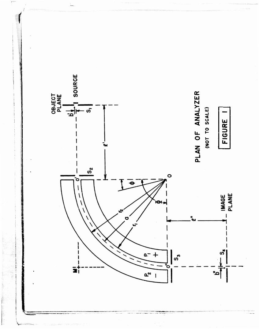
Pig. 1 is a plan of the analyzer. There are four pairs of beam
and field defining slit systems, Tho object slit S-^ is in the object
act• Accompanying Technical Report,
2
\
V-
i
QC UJ IM
5 < Z <
UJ
< o UJ
iL. o
o
1- w
o u. 2 z < -1 Q.
^~
V-
'
piano 30" fror.i the entrance end or the analyzer« Slii-,3 Sg en'i S-j,
located at tho entrance and exit ends of tho analyzer, aerve to limit
the extent of the electric field. Herzogfi has shown that for the gap
width of 0,304", the fringe field at tho ends of the analyzer can be
considered zero if Sg and S3 have total widths of 0o150" and are
spaced 0.060" from the plates P, and Pg. Slit S4 is in the Image
plane located 11.3" from the exit end of the analyzer.
Since we pli.n to use this analyzer for further beta ray spectro-
taotry, (necessitating frequent relocation of S4 ) it was decided to
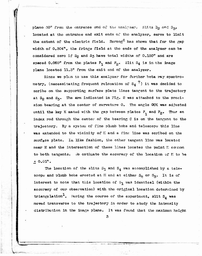
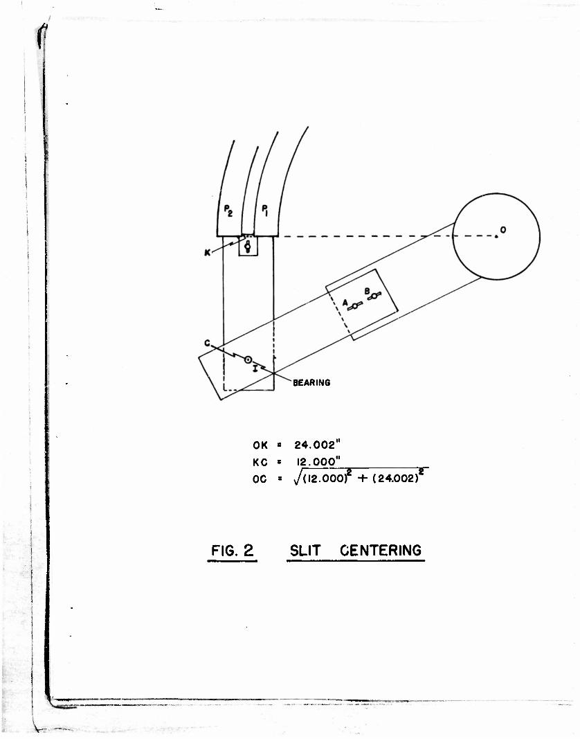
scribe on the supporting surface plate lines tangent to the trajectory
at Sp and S3. The arm indlcatod in Pig. 2 was attached to the preci-
sion bearing at the center of curvature 0. The angle 0CK was adjusted
until the key K mated with the gap between plates P and P«. ThuF an
index rod through the center- of the bearing C is on the tangent to the
trajectory. By a system of fine plumb bobs and telescope this line
was extended to the vicinity of I.I and a fine line was scribed on the
surface plate„ In like fashion, the other tangent line was located
near K and the intersection of these lines locates the point !.* cannon
to both tangents. .Ve ostiuato the accuracy of tho location of It to be
• 0.01".
The location of the slits S^ and S4 was accomplished by a tele-
scope and plumb bobs erected at II and at either S« or S^. It is of
interest to note that this location of S, was identical (within the
accuracy of our observation) with the original location determined by
triangulation . louring the course of the experiment, slit S4 was
moved transverse to the trajectory in order to study the intensity
distribution in the image plane. It was found that the maximum height
3
-BEARING
OK * 24.002"
KC « 12.000"
oc • Juz.ooof (24.002)
FIG. 2 SLIT CENTERING
•
f or the K peak occured when 3^ was located on the previously determined
tangent line
B ttagnotic Field Mapping,,
Noye3 et al Measured tho magnetic field in th? electrostatic
analyzer using a flip coil and ballistic galvanometer. Due to the
limitation of the size of the flip coil the deflections were only a
few millimeters. Consequently, the more sensitive p* aking 3trip^
method was used in this experiment.
A strip (1/16" x 3/8" x „005" ) of Delta-max was inserted into
tho center of a 1000 turn coil of i'\0 cooper wire wound >n a Lucite
spool (0.40" x 0.15"). This prob', was small enoufij to ^loar the
plates of the analyzer and was mounted on the ann pi vote*.! it 0 for
the manning between 0» and 0".
The probe, Pic. 3A, was U3ed as one of the arms of tY.i :>xwell
bridge (Pic* 3D). The oscillate, was a Hewlitt .'ickard 20C-C ana '.he
detector v/as a Hewlitt Packard COO-A ave Analyzer, Tt can be shown
tliat any even order harmonic generated in such a orobc is nractically
a linear function of the extornal magnetic field. Consequently, the
oscillator v/as set at 5KC and tho analyzer at 10K.C. The bridge serves
two purposes: 1) by first balancing the bridge with tho probe in zero
field and with the oscillator at 10KC, the second harmonic content of
the oscillator (..-hen set at 5MC) is negligible at the detector termi-
nals; 2) because the Maxwell bridge is frequency independent {~*tr
linear olouents) the bridge is nearly balanced at ?-" - and -bus does
not saturate the detector,,
This device was calibrated in the C.old of a s:,; nda -d solenoid
for an oscillator voltage of 10 v/oits at 3KCa The calibration curve,
4
v

n^LUCITE SPOOL
f$sm ^^ MAGNETIC
STRIP
1000 TUKNS
FIG. 3A PR0BE UN,T
FIG. 3B BRIDGE CIRCUIT FOR MAGNETIC PROBE
OSC* HEWLETT-PACKARD OSCILLATOR 200-C DET.« HEWLETT-PACKARD WAVE ANALYZER 300-A
T • UTC TYPE 0-1 LINE TO GRID
R, «50K R4»50K C • 0.0047MF
P * PROBE
R2« IK IK
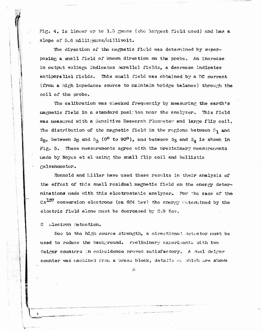
i Fig. 4, Is linear up to 1^5 gauss (tho largest field used) and lias a
slope of 5.6 milligauss/millivolt.
The diroction of the magnetic field was determined by super-
posing a snail field of known diroction on the probe. An increase
in output voltage indicates parallel fields, a decrease indicates
antiparallol fields. This snail field was obtained by a DC current
(from a Mgh inpedance source to naintaln bridge balance) through the
coil of tho probe.
Tho calibration was checkod frequently by measuring the earth!3
magnetic field in a standard posi' ion near the analyzer. Tiiis field
was measured with a Sensitive Research Plu>3-1ete,., and large flip coil.
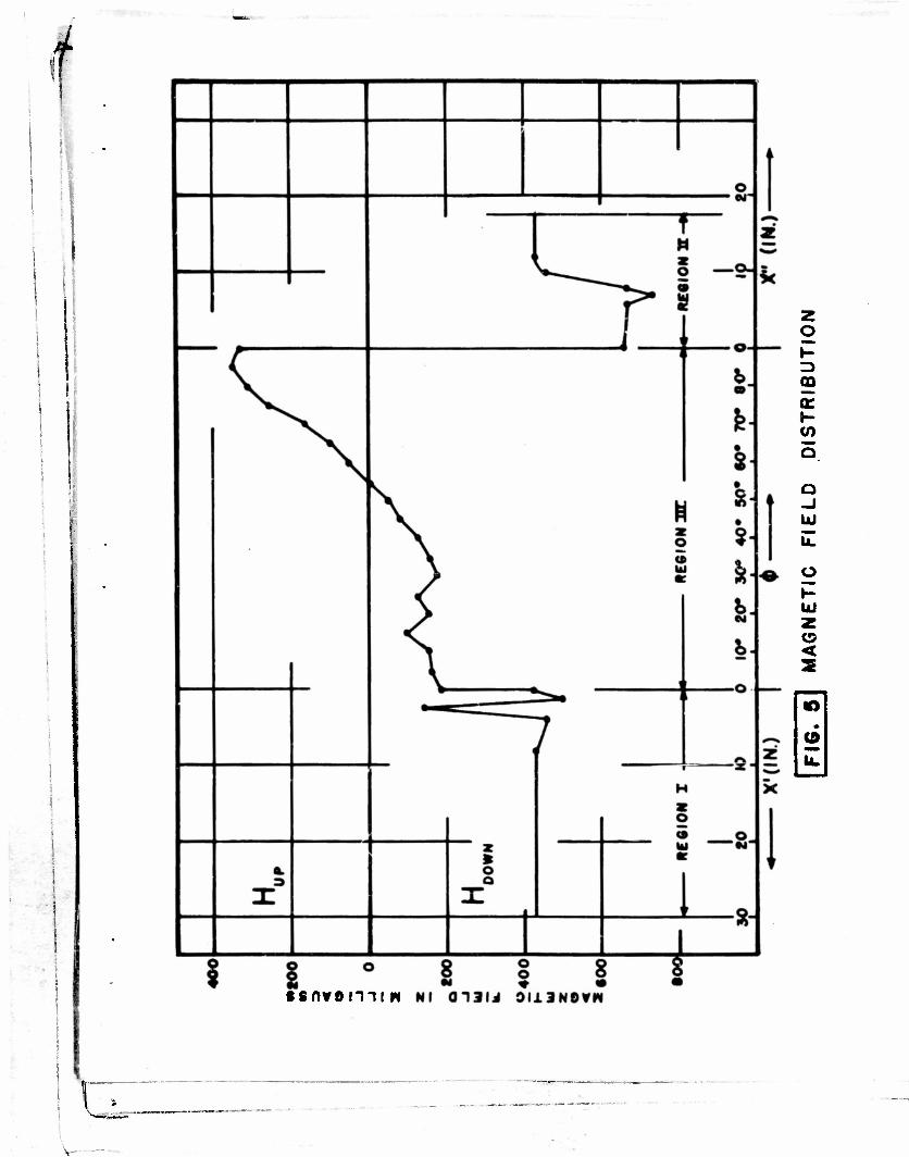
The distribution of the magnetic field in the regions between r.^ and
S2, between S2 and S, (0° to 90°), and betwoer S3 and 34 is shown in
Fig. 5. These measurements agree with the oreliminary measurements
made by Noycs et al using tho small flip coil and ballistic
galvanometer.
Honnold and Killer have used these results in their analysis of
the effect of thi.3 small residual magnetic field on the energy deter-
minations nado with this electrostatic analyzer. Fov "he case of the
03^" conversion electrons (ca 624 kev) the energy 1 determined by the
electric field alone must be decreased by 209 Kov0
\\
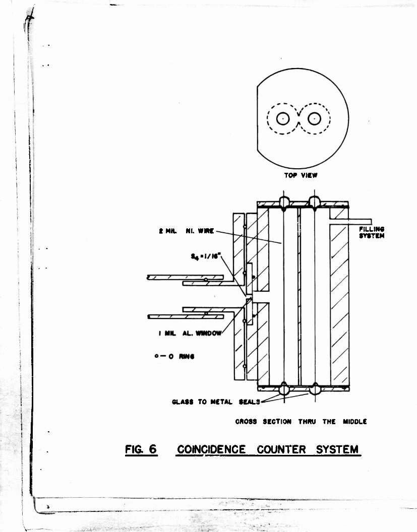
C electron Detection,
Due to tho high source strength, a directional detector must be
used to reduce the background. Preliminary experiments with tv/o
Geiger counters in coincidence proved satisfactory9 A tlual Geiger
counter was machined from a brass block, details oJ which n.v& shown
V-
.w
«D
. 1
1 i
e>
ST10AITUN Nl 0INOH8VH 0N003S
U
I
• snvonii w
m a:
Q -J UJ
\L
o
UJ z <
"io
1
i ; 1
' -
T0# VIEW
t MIL Nl. wnc FILLING SYSTEM
GLASS TO MCTAL SEALS
CROSS SECTION THRU THE MIDDLE
• FIG. 6 COINCIDENCE COUNTER SYSTEM
i • *T
i
i
Vr
in Fig. S» The gas filling was the conventional argon-othyl alcohol
mixture. Doth halves of the counter had the same characteristics
and were operated at 1150 volts.
The coincidence background counting rate was 100 per 10 minute
interval and remained constant throughout all the oxoeriments.
D Source Preparation.
The electrostatic analyzer subtends a very small solid angle and
consequently necessitates a strong source,, The Cs^' that was oro-
cured from the Oak nidge national Laboratory was in the chloride form
in an HC1 solution. The CsCl2 was evaporated to dryncs3 Tinder a heat
lamp, thon dissolved in distilled water and re-evaporated to dryness,
Tliis process was repeated several times and resulted in the removal
of the HG1. A few drops of the CsCl2 in a distilled water solution
were then permitted to evaporate on a 1 mil aluminum foil, first
treating the foil with insulin to promote even spreading-^. The
source was 0.04" x 0.5" in size to correspond to slit S^ and of
approximately 2 to 3 millicuries strength. The source, on its alumi-
num foil backing, was mounted directly behind slit S-^ and grounded
electrically to avoid charging effects.
Ill RKSHLTS A Iff) DISCUSSION
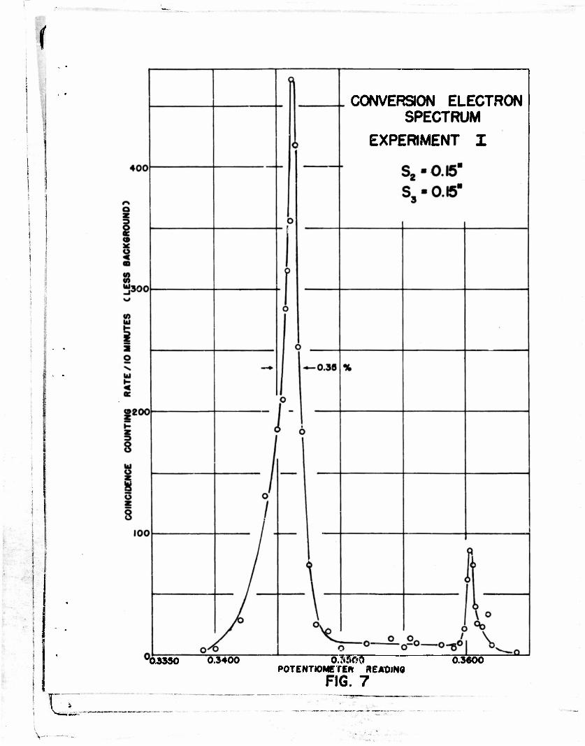
Fig. 7 is a plot of the net coincidence rate versus potentiometer
reading of voltage across the electrostatic analyzer plates„ Slits
Sg and S3, which act as guard slits at the entrance and exit of the
analyzer, were set at 0.15", a value which made the fringe field zero0
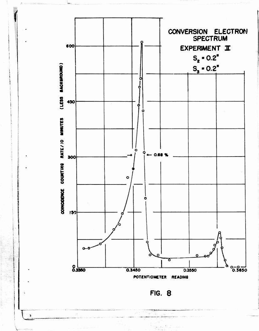
In order to obtain greater Intensity slits Sp and S3 were
widened to 0.20". Fig. 8 is n plot of the data. The increased
6
*
CONVERSION ELECTRON SPECTRUM
EXPERIMENT I
"03330 0.3400 o7<57>3~ POTENTIOMETER READING
FIG. 7 0.3600
d—: v- •
<
600
i 430
6 900
ISO
0JS50
CONVERSION ELECTRON SPECTRUM
EXPERIMENT I
0.3490 9.3930
POTENTIOMETER READING
o—O- 0.3630
FIG. 8
v— • •
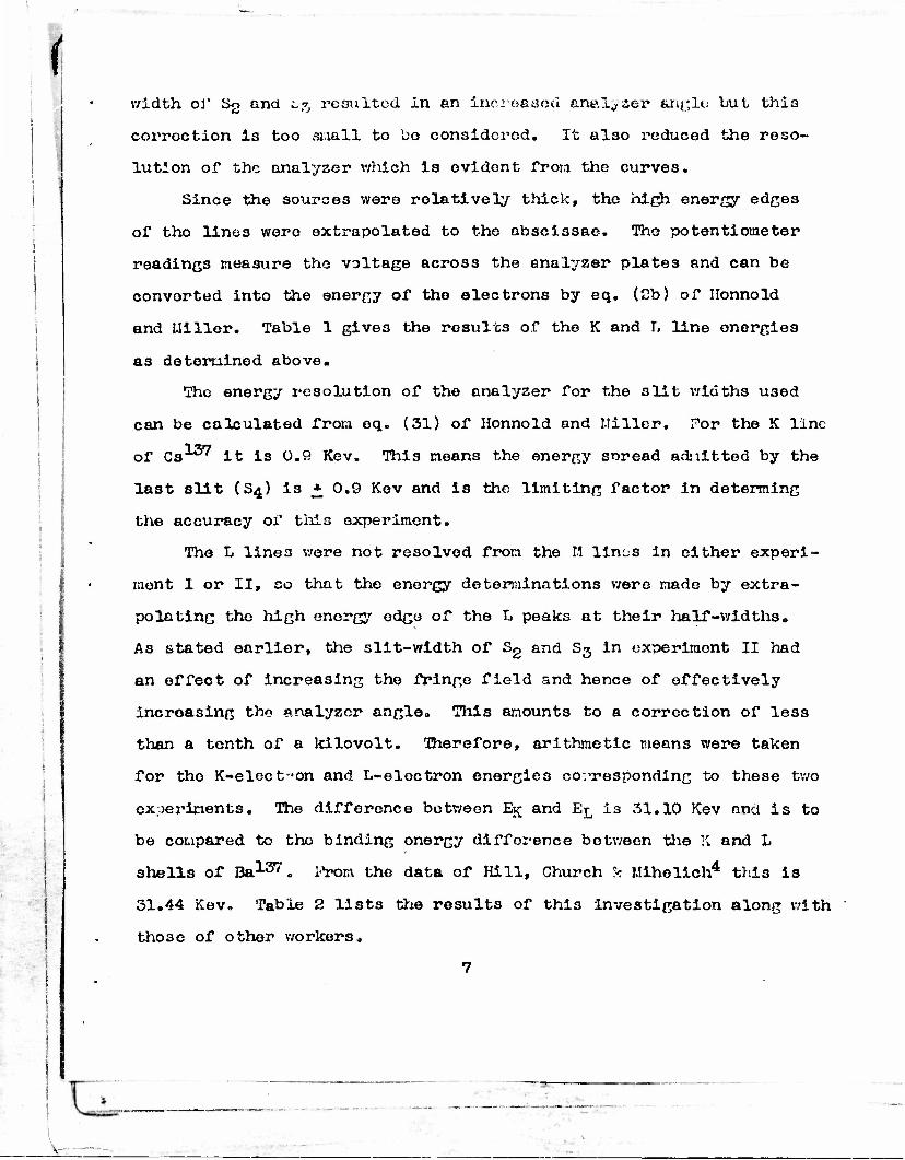
width ol* t>2 &nd 1*% resulted in an increased anaTL^ser angle but thi3
corroction is too small to 00 considered. It also reduced the reso-
lution of the analyzer which is evident from the curves.
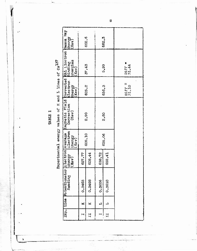
Since the sources were relatively thick, the high energy edges
of tho lines were extrapolated to the abscissae. The potentiometer
readings measure tho voltage across the analyzer plates and can be
convorted into the energy of the electrons by eq. (2b) of Ilonnold
and Miller. Table 1 gives the results of the K and T, line energies
as determined above.
The energy resolution of the analyzer for the slit widths U3ed
can be calculated from eq. (31) of Ilonnold and Miller. For the K line
of Ca 37 it is 0.9 Kev. This means the energy soread admitted by the
last slit (S4) is * 0.9 Kev and is the limiting factor in determing
the accuracy of this experiment.
The L line3 were not resolved from the M lin/js in either experi-
ment I or II, so that the energy determinations were made by extra-
polating tho high energy edge of the L peaks at their half-widths.
As stated earlier, the slit-width of Sg and S3 in experiment II had
an effect of increasing the fringe field and hence of effectively
incroasing the analyzer angle. This amounts to a correction of less
than a tenth of a kilovolt. Therefore, arithmetic means were taken
for tho K-electr-on and L-eloctron energies corresponding to these two
experiments. The difference between E^ and ETQ is 31.10 Kev and is to
be compared to tho binding onergy difference between the K and L
shells of Ba137. From the data of Hill, Church k Mihelich4 this is
31.44 Kev» Table 2 list3 the results of this investigation along with
those of other workers,
7
V- --
(
8
:•
H in o v. o
© c H
>1
n c 01
«
0
m ©
09 >
to © c ©
OS -p c © G
U © a
*>> »
6) a -&- •. to
0 2 >H > CM oo so.© to to is* to to
c 0 fc •p V Cl o to © •
rH CVl to 0> •tf r-)«H tC <* 05 <M "<* ,T3 ^1 > • • <^( •
»J C © © fc
LO •H H
jfi£SS D tO
•o © c
•P o II
© -p S^-» co to O
ft ft <H H hut*> lO to <H • St © © ,© ca to •rl H OH C W to to Q tO
•0 H © C
•H O &, »H
•P"-> O O > o o
•rH © © 05 CO +> & w » ft © fc-^ CO w &o * 22
C © O o to to Pi £> H o
j at -P tO—» • « U o U > CO 05 © © © © N iO
S3S* to to
c p ^ D- «* OJ H u >> t- «* c- •<*
•p fc&-^ i • • • o fc > O CO CO o
335 to 01 to
to to
to to
(4 © •P © t3 6 C OnH IO CO to o
•HTJ -p as
to to a H •«< S to to
c © CO to to ©« ft ft • e
4-> o o o o O e* © c w M IJ t-3
»J
• Q.
; M H
H M H
M 1
'
F>
-.
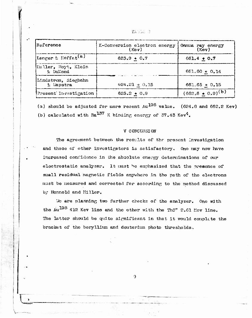
TAiyyc 2
Reference K-Conversion electron energy (Kev)
Gamma ray energy (Kev)
Langer !c !.;offat^a^ 623.9 • 0.7 661.4 ± 0.7
I.'.uller, Hoyt, Klein S; DuLlond 661*60 + 0.14
Lindstrom, Siegbahn S: Wapstra t>24.21 •<>. 0,15 661,65 * 0.15
•
Present' Investigation i. __
625.2 • 0U9 (662,6 • 0.9)(b)
1
(a) should bo adjusted for more recent Au-1-98 value. (624„0 and 662.2 Kev)
(b) calculated with Ba137 K binding energy of 37.43 Kev4.
V CONCLUSION
The agreement between the results of the present Investigation
and those of other investigators is satisfactory., One may now have
incroased confidonce in the absolute energy determinations of our
electrostatic analyzer. It must ^e emphasized that the preaonce of
small residual magnetic fields anywhero in the path of tho electrons
must be measured and corrected for according to the method discussed
by Honnold and Miller.
We are planning two further checks of the analyzer. One with
tho Au198 412 Kev line and the other with the The" 2.61 r.cv line.
The latter should be quite significant in that it would complete the
bracket of the beryllium and detiterium photo thresholds,,
\ -
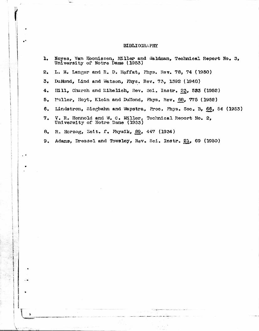
r BIBLIOGRAPHY
1. Noyes, Van Hooraissen, Miller and tfaldman. Technical Report No. 3, University of Notre Dame (1953)
2. Li M. Langer and R. D, Moffat, Phya. Rev. 78, 74 (1950)
3. DuMond, Lind and Watson, Phys. Rev. 73, 1392 (1940)
4. Hill, Church and Mihelich, Rev. Sci. Instr. 23, 533 (1952)
5. Kuller, Hoyt, Klein and DuMond, Phys. Rev. 88, 775 (1952)
6. Lindstrocx, Siegbahn and Wapstra, Proc. Phys. Soc. B, 66, 54 (1953)
7. V. R. Honnold and VV, C. Miller, Technical Report No. 2, University of Notre Dane (1953)
8. R, Horzog, Zoit. f. Physik, 89, 447 (1934)
9. Adams, Dressel and Towsley, Rev. Sci. Instr. 21, 69 (1950)
V-
Armed Services Technical Information Agency Because of our limited supply, you are requested to return this copy WHEN IT HAS SERVED YOUR PURPOSE so that it may be made available to other requesters. Your cooperation will be appreciated.
NOTICE: WHEN GOVERNMENT OR OTHER DRAWINGS, SPECIFICATIONS OR OTHER DATA ARE USED FOR ANY PURPOSE OTHER THAN IN CONNECTION WITH A DEFINITELY RELATED GOVERNMENT PROCUREMENT OPERATION, THE U. S. GOVERNMENT THEREBY INCURS NO RESPONSIBILITY, NOR ANY OBLIGATION WHATSOEVER; AND THE FACT THAT THE GOVERNMENT MAY HAVE FORMULATED, FURNISHED, OR IN ANY WAY SUPPLIED THE SAID DRAWINGS, SPECIFICATIONS, OR OTHER DATA IS NOT TO BE REGARDED BY IMPLICATION OR OTHERWISE AS IN ANY MANNER LICENSING THE HOLDER OR ANY OTHER PERSON OR CORPORATION, OR CONVEYING ANY RIGHTS OR PERMISSION TO MANUFACTURE, USE OR SELL ANY PATENTED DJVENTION THAT~MAY IN ANY WAY BE RELATED THERETO.
Reproduced by
DOCUMENT SERVICE CENTER KNOTT BUILDING, DAYTON, 2, OHIO