Embed Size (px)
Citation preview

DIOMEDES WP5 Page 1/48
DIstribution Of Multi-view Entertainment using cont ent aware
DElivery Systems
DIOMEDES
Grant Agreement Number: 247996
D5.3
Server, peer, and user terminal proof of concept pr ototypes

DIOMEDES WP5 Page 2/48
Document description
Name of document Server, peer, and user terminal proof of concept prototypes
Abstract This report describes fully functional proof of concept prototypes, for the user terminal, main server, and the peer (including content authentication) that meets the specifications described in D5.1. This report describes software prototypes for the user terminals, main server, and the peers that are reported in D5.2.
Document identifier D5.3
Document class Deliverable
Document type PU
Version 1.3
Author(s) E. Dogan, S. Marangoz, O. Solakoglu, H. Gokmen (ARCELIK), G. Gurler (KOC), P. Kovacs, K. Lackner (HOL), J. Hasselbach, T. Korn (IDMT), E. Ekmekcioglu, S. Dogan, S. Worrall, A. Kondoz (UniS), T. Adari (OPTEC), N. Just (IRT)
QAT team Y. Lapid (OPTEC), P. Kovacs (HOL)
Date of creation 16 December 2011
Date of last modification 30 January 2012
Status Final
Destination European Commission
WP number WP5

DIOMEDES WP5 Page 3/48
TABLE OF CONTENTS 1 INTRODUCTION ................................................................................................................ 7
1.1 Purpose of the document ...................................................................................... 7 1.2 Scope of the work .................................................................................................. 7 1.3 Objectives .............................................................................................................. 7 1.4 Structure of the document ..................................................................................... 7
2 SERVER SOFTWARE PROTOTYPE ................................................................................ 8
2.1 3D Content Server ................................................................................................. 8 2.1.1 Transport Stream Chunker ...................................................................................................... 8 2.1.2 MPEG2 Transport Stream Multiplexer ................................................................................... 9 2.1.3 MPEG2 Transport Stream Playout ......................................................................................... 9
2.2 Access Control and Content Registration Server (Security Server) ..................... 9 2.3 P2P Main Seed Server ........................................................................................ 10
3 PEER SOFTWARE PROTOTYPE ................................................................................... 12
3.1 P2P Software Module .......................................................................................... 12 3.1.1 Download Manager ................................................................................................................. 13 3.1.2 Neighbour Manager ................................................................................................................ 14 3.1.3 Player Manager ....................................................................................................................... 14 3.1.4 Report Manager ...................................................................................................................... 14 3.1.5 Tracker Manager ..................................................................................................................... 15 3.1.6 Event Scheduler ...................................................................................................................... 15 3.1.7 Main Listener ........................................................................................................................... 15
3.2 Authentication + Decryption Module (Security Client) ......................................... 16
4 USER TERMINAL SOFTWARE PROTOTYPE ............................................................... 17
4.1 Interaction Device Module ................................................................................... 17 4.1.1 Software Architecture ............................................................................................................. 18 4.1.2 User Controls ........................................................................................................................... 18
4.1.2.1 Module Execution .............................................................................................................. 18 4.1.2.2 Module Parameters ........................................................................................................... 19 4.1.2.3 Content Selection............................................................................................................... 19 4.1.2.4 Content Upload .................................................................................................................. 20 4.1.2.5 Viewpoint ............................................................................................................................. 20 4.1.2.6 Debug Messages ............................................................................................................... 20
4.2 Control Module .................................................................................................... 20 4.3 Adaptation Decision Engine Module ................................................................... 22
4.3.1 Message-driven Adaptation Decision Making ..................................................................... 22 4.3.2 Module Configuration and Features ..................................................................................... 23 4.3.3 Running and Debugging ADEM ............................................................................................ 23
4.4 DVB-T Receiving Module .................................................................................... 23 4.5 AV Sync. & Demux & Buffer Module ................................................................... 24
4.5.1 Overview .................................................................................................................................. 24 4.5.2 Interfaces .................................................................................................................................. 25 4.5.3 Building Blocks ........................................................................................................................ 25
4.6 Audio Cluster ....................................................................................................... 27 4.6.1 Hardware Platform .................................................................................................................. 27 4.6.2 Software Environment ............................................................................................................ 27 4.6.3 Development Encironment .................................................................................................... 27 4.6.4 Internal Audio Cluster Modules (for DIOMEDES terminal use) ........................................ 27
4.7 Video Cluster ....................................................................................................... 29 4.7.1 Decoder Control Module ........................................................................................................ 29
4.7.1.1 Module Architecture ........................................................................................................... 30 4.7.1.2 JSON messages ................................................................................................................ 30 4.7.1.3 Module configuration and features .................................................................................. 30 4.7.1.4 Running and debugging the Decoder Control Module ................................................. 31
4.7.2 ES Demultiplexing Module ..................................................................................................... 31 4.7.2.1 Module Architecture ........................................................................................................... 31 4.7.2.2 JSON messages ................................................................................................................ 32

DIOMEDES WP5 Page 4/48
4.7.2.3 Module configuration and features .................................................................................. 32 4.7.2.4 Running and debug the Decoder Control Module ......................................................... 33 4.7.2.5 Debug Information ............................................................................................................. 34
4.7.3 Video Decoder ......................................................................................................................... 34 4.7.3.1 Module Architecture ........................................................................................................... 34 4.7.3.2 Command Line Options .................................................................................................... 35
4.7.4 Video Rendeder ...................................................................................................................... 35 4.7.4.1 Module Architecture ........................................................................................................... 35 4.7.4.2 Command line options ...................................................................................................... 36 4.7.4.3 JSON Messages ................................................................................................................ 36 4.7.4.4 Keyboard shortcuts ............................................................................................................ 37 4.7.4.5 Interfaces Between Video Decoder and Video Renderer ............................................ 37 4.7.4.6 Debugging interface .......................................................................................................... 38
5 CONCLUSIONS ............................................................................................................... 39
APPENDIX A: CONTROL MODULE – INPUT JSON MESSAGES .. ...................................... 40
APPENDIX B: CONTROL MODULE – OUTPUT JSON MESSAGES . ................................... 41
APPENDIX C: CONTROL MODULE – CONFIGURATION FILE ... ......................................... 46
APPENDIX D: ADAPTATION DECISION, DECODER CONTROL MO DULE AND ESDEMUX – CONFIGURATION FILE .............................. .......................................................................... 47
DIOMEDES WP5 Page 5/48
LIST OF FIGURES
Figure 1 – Server Overview ....................................................................................................................... 8
Figure 2 – State Diagram of Thread 1 in Main Seed Server .................................................................... 11
Figure 3 – Simplified model for P2P Software .......................................................................................... 13
Figure 4 – Chunk Download Window ....................................................................................................... 14
Figure 5 – Download Rate Window .......................................................................................................... 15
Figure 6 – User Terminal Overview.......................................................................................................... 17
Figure 7 – Interaction Device ................................................................................................................... 18
Figure 8 – Interaction Device & Control Module Connection .................................................................... 18
Figure 9 – Module Execution ................................................................................................................... 19
Figure 10 – Content Selection .................................................................................................................. 19
Figure 11 – User Login and Upload Content ............................................................................................ 20
Figure 12 – Listener and Sender Thread block diagram .......................................................................... 21
Figure 13 – Listener and Sender mechanism .......................................................................................... 22
Figure 14 – Message-driven adaptation decision making mechanism ..................................................... 23
Figure 15 – AvSync block diagram........................................................................................................... 26
Figure 16 – Main parts of the internal structure of the Audio Cluster ....................................................... 29
Figure 17 – Decoder Control Module block diagram ................................................................................ 30
Figure 18 – EsDemux Module functional diagram ................................................................................... 32
Figure 19 – Snapshot of EsDemux Module log file .................................................................................. 34
Figure 20 – Main components of the Video Renderer .............................................................................. 36
Figure 21 – Debugging screen of the Video Renderer ............................................................................. 38

DIOMEDES WP5 Page 6/48
LIST OF TABLES
Table 1 – Command Line Options of the Video Decoder ......................................................................... 35

DIOMEDES WP5 Page 7/48
1 INTRODUCTION
1.1 Purpose of the document
The purpose of this document is to provide description of the software prototypes of all server modules, peer modules, and user terminal modules within DIOMEDES structure. Module development platforms, library dependencies, and necessary software tools are specified. Besides, software block diagrams and structures are described to have a better understanding about modules.
1.2 Scope of the work
The scope of the work presented in this document is to describe prototypes of the software needed for the delivery of the media, as detailed in following: the main server software that will manage the P2P network, the content-aware P2P networking software and media players for end users.
1.3 Objectives
The objective of this document is to have a clear understanding of modules' software. It presents detailed interface definitions of sub-systems and system components. All the user controllable features of modules are presented in the document.
1.4 Structure of the document
Server software prototype is described in Chapter 2. Chapter 3 covers the peer software prototypes. The user terminal software prototypes descriptions are provided in Chapter 4. Chapter 5 includes conclusions. Finally, Appendix-A, -B, -C, -D contain Control Module input/output messages, configuration file of control module, and configuration file of Adaptation Decision / Decoder Control / Es Demux modules respectively.

DIOMEDES WP5 Page 8/48
2 SERVER SOFTWARE PROTOTYPE
The main server seeds the network with content, thereby closely cooperating with the content and user registration server. Approved content will be acquired from the encoders through an IP network or from pre-encoded material saved in a storage system, the stream will be tagged with metadata, and the content server will send the data to the top level nodes of the P2P network. The server will also manage the authentication of the users and will control a database of connected nodes in order to make it possible that network peers can discover each other.
Server mainly consists of 3D Content Server, Content Registration Server (Security Server), and P2P Main Seed Server as depicted in Figure 1.
Figure 1 – Server Overview
2.1 3D Content Server
The 3D Content Server generates the broadcast services from available 3D Content. It multiplexes MPEG2-TS as input for the DVB-T Transmission and the P2P Main Seed Server. The 3D Content Server consists of the following components.
2.1.1 Transport Stream Chunker
The TsChunker Module receives transport streams either from live input using UDP/IP or from file input, filters all transport stream packets but those containing audio or video and uploads the data as chunks to the Access Control and Content Registration module (see 2.2). Additionally the JSON meta-data file for the processed content is packed into an information chunk. The chunk size is depending on the GoP for video. For audio there is a size and a time limit.
The TsChunker Module is a single console application written in C# and uses Json.Net 4.0 r2 library.
DIOMEDES WP5 Page 9/48
Interfacing with other modules
This module is only communicating with the Access Control and Content Registration Module which provides an interface based on SOAP. For debugging purposes there is also a UDP output option.
Operation modes
The TsChunker Module can be operated in real-time or faster when reading input transport stream from file. The module can also be used for PCR-PTS analysis.
Software dependencies
The TsChunker is running on Windows 7 OS and requires .NET 4.0.
2.1.2 MPEG2 Transport Stream Multiplexer
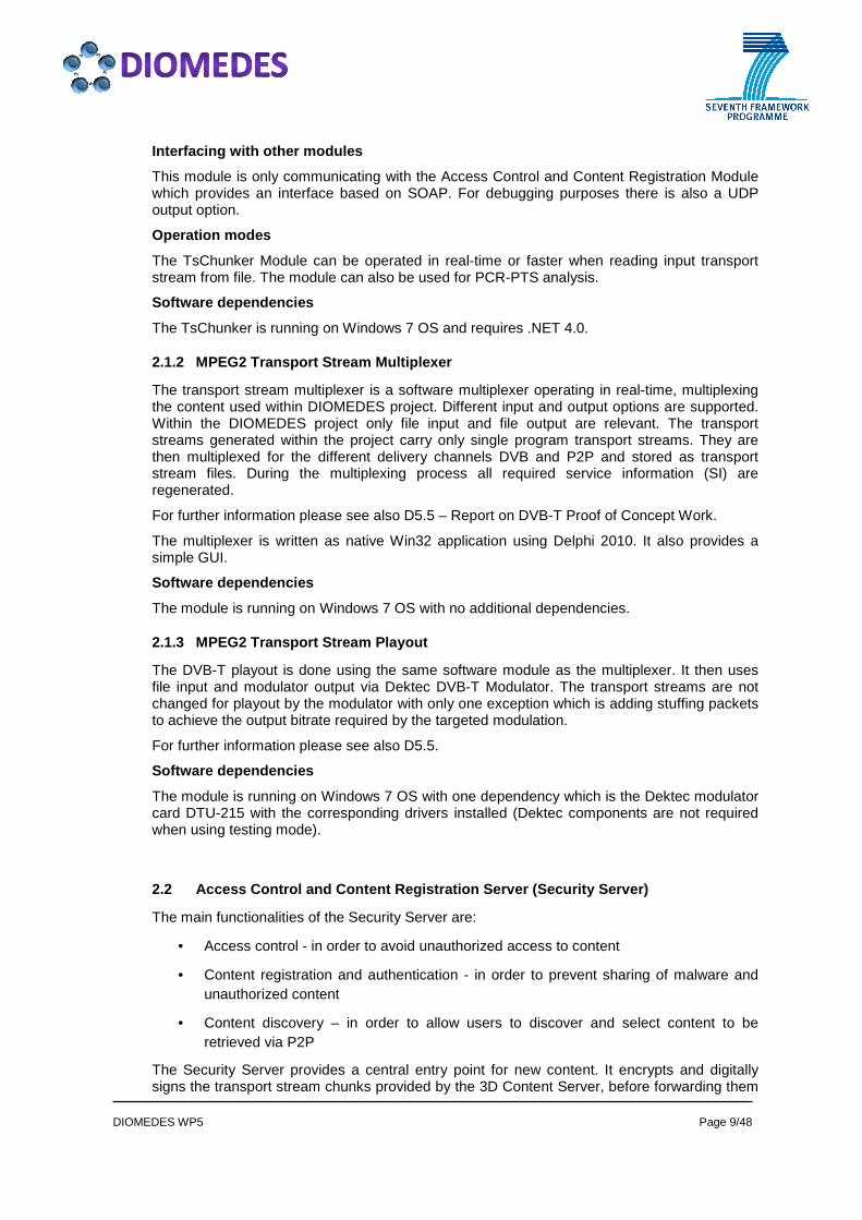
The transport stream multiplexer is a software multiplexer operating in real-time, multiplexing the content used within DIOMEDES project. Different input and output options are supported. Within the DIOMEDES project only file input and file output are relevant. The transport streams generated within the project carry only single program transport streams. They are then multiplexed for the different delivery channels DVB and P2P and stored as transport stream files. During the multiplexing process all required service information (SI) are regenerated.
For further information please see also D5.5 – Report on DVB-T Proof of Concept Work.
The multiplexer is written as native Win32 application using Delphi 2010. It also provides a simple GUI.
Software dependencies
The module is running on Windows 7 OS with no additional dependencies.
2.1.3 MPEG2 Transport Stream Playout
The DVB-T playout is done using the same software module as the multiplexer. It then uses file input and modulator output via Dektec DVB-T Modulator. The transport streams are not changed for playout by the modulator with only one exception which is adding stuffing packets to achieve the output bitrate required by the targeted modulation.
For further information please see also D5.5.
Software dependencies
The module is running on Windows 7 OS with one dependency which is the Dektec modulator card DTU-215 with the corresponding drivers installed (Dektec components are not required when using testing mode).
2.2 Access Control and Content Registration Server (Security Server)
The main functionalities of the Security Server are:
• Access control - in order to avoid unauthorized access to content
• Content registration and authentication - in order to prevent sharing of malware and unauthorized content
• Content discovery – in order to allow users to discover and select content to be retrieved via P2P
The Security Server provides a central entry point for new content. It encrypts and digitally signs the transport stream chunks provided by the 3D Content Server, before forwarding them

DIOMEDES WP5 Page 10/48
to the P2P Main Seed Server. Moreover, this component is responsible for the management of keys and receivers - including key generation, storage and efficient key distribution using the available broadcast channels. The Security Server generates so called P2P chunks consisting of a P2P chunk header and the actual payload. The payload can contain encrypted and signed A/V data, signed content metadata, or signed key information generated by the Security Server. For more detailed information including APIs, workflows and the implemented broadcast encryption scheme, please refer to D5.4 – Security Components Prototypes.
2.3 P2P Main Seed Server
Tasks of Main Seed Server:
1. Receive and store multimedia chunks, info chunk (content metadata) and session key from the Access Control and Content Registration Server
2. Perform sanity check on received content
3. Act as a tracker server and connect new coming peers to the rest of the swarm
4. Distribute stored data to the peers
In order to perform first three tasks, the main seed server runs two separate threads, each running in an endless loop (unless the software is terminated). For the final task, the main seed server uses a web server (e.g., Apache web server).
Thread 1 handles the first and second tasks above. Figure 2 depicts the states of Thread 1 and presents run logic. Thread 1 start is S1 state, waiting for a metadata chunk to initialize a new session. Following that it expects a key chunk followed by session chunks. Once the session is over (indicated by a final chunk with payload size 0) it performs content validation. If validation is successful, it stores the content to the web server, in all unexpected states it displays a warning and goes back to state 1.
Thread 2 handles new coming peers in a similar fashion. Thread 2 waits on a TCP socket for incoming connections. Upon reception of connections it launches a sub-thread to handle peer communication, while it goes back to listening on the TCP socket. After this stage the sub-thread handles the communication with the peer. It first receives the session-id that the peer wants to join. Then receives information about the current state of the peer and stores it in its memory. Once the state of the peer is updated, based on the peer's request, the tracker server can return a sublist of peers that is available in the network.
The web server provides web seeding service for the P2P Network. If a chunk is not available in the P2P overlay, then peers can request a chunk via HTTP protocol. One of the goals of DIOMEDES P2P is to keep the requests from Main Seed Server as low as possible, which is described in the following.

DIOMEDES WP5 Page 11/48
Figure 2 – State Diagram of Thread 1 in Main Seed Server

DIOMEDES WP5 Page 12/48
3 PEER SOFTWARE PROTOTYPE
This chapter describes a prototype working peer, which contains the content aware P2P software suite. The P2P software will get the best peers (e.g. peers with the best connection quality, best content availability) for receiving the necessary data from the network in order to display the desired video and viewpoint. The peers have to monitor their neighbours in order to act quickly in cases when the connection is lost with other nodes so the end user does not notice any interruption in the stream. The peer software also integrates functionalities provided with respect to content security and authentication.
3.1 P2P Software Module
The P2P software is developed in Java programming language for easy deployment in any modern operating system. Considering the tasks it has to perform, it is a quite complicated module. We do not use any external library related to P2P communication and rather implement our own methods to perform P2P distribution. The reasons for using a new protocol have been introduced in D4.5 – Report on performance of integrated MD-SMVD and P2P system.
The tasks of P2P protocol is as follows:
1. Receive chunks from the main seed server and other peers
2. Forward chunks to the Authentication + Decryption Module
3. Perform content retrieval in synchronization with the DVB (if available).
4. Inform neighbours about the availability of chunks (successful download).
5. Forward downloaded chunks to other peers upon request.
6. Receive adaptation decision ranking from Adaptation Decision Engine
7. Perform adaptation based on the state of the network and the state of the video buffer.
In order to perform these tasks in an organized way most of them are performed by separate threads that are called managers. A manager is a thread that loops until its tasks are over (e.g., the Player Manager loops until it forwards all chunks to next module). The duration of each iteration is calculated to understand if a certain task delays a manager. For instance, if Player Manager cannot forward a chunk to another module within predefined timeout duration then it displays a warning message indicating that there can be a problem with the connection.
The managers, while specified for different tasks, are also need to be aware of each other. For example, the Player Manager is responsible for storing the clock updates of the DVB channel because based on the information the Player Manager can skip outdated chunks and forward correct data. However, this information is also important for the Download Manager as there is no gain in downloading a chunk that will not be forwarded to players. For such cases, managers share a data structure that is called Event Scheduler, which allows managers to communicate with each other using events as messages. For example, the Player Manager updates the state of the buffer using BufferUpdateEvent. The Download Manager can use the BufferUpdateEvent data and its download rate to estimate the next couple of seconds and perform rate adaptation.
In addition to message exchanges, the Managers share some data structures that provide information on content (e.g., number of views, PIDs) or the state of the session (e.g., list of peers that are connected to this node). In order to avoid race conditions, such structures are modified using locks in a secure way.
Figure 3 presents a simplified overview of the P2P software. In the following sub-sections, description of the list of manager and its work will be provided.

DIOMEDES WP5 Page 13/48
DIOMEDES CLIENT
P2P Software Module
Main
Listener
Event
Scheduler
Chunk
Scheduler
Chunk
Downloader
Tracker
Manager
Download
Manager
Neighbor
Manager
Player
Manager
Report
Manager
Chunk
Scheduler
Chunk
Scheduler
Peer
Handler
Chunk
Downloader
Chunk
Downloader
Decryption
Module
Feedback
GUI
AV Sync.
Module
Control
Module
Main Seed ServerOther Peers
P2P Data
Structures
Legend
DIOMEDES
Module
Helper
Thread
Manager
Thread
Network
Connection
Method
Call
Event Path
Event
Figure 3 – Simplified model for P2P Software
3.1.1 Download Manager
Download Manager is responsible for downloading chunks from the Internet. For this purpose it periodically requests new chunks from Chunk Scheduler and assign a Chunk Downloader thread when a new chunk is available in download window (See D4.5). Download Manager is responsible for the following tasks.
1. Receiving chunks from the main seed server and other peers
2. Creating a download complete event (intended for Neighbour Manager)
3. Performing adaptation based on the state of the network and the state of the video buffer.

DIOMEDES WP5 Page 14/48
3.1.2 Neighbour Manager
Neighbour Manager handles the communication with the peers that the node is connected to. It is the task of Neighbour Manager to listen for incoming chunk requests and reply accordingly. Moreover, upon reception of ChunkDownloadComplete event, it notifies the neighbours about the availability of the chunk.
3.1.3 Player Manager
Player Manager is responsible for forwarding downloaded chunks to players (via Decryption Module) in a sequential order. In addition to that, Player Manager periodically generates BufferUpdateEvent which is intended for both the Download Manager and Report Manager objects. If a chunk has to be terminated, this event also notifies that to the those managers. The Player Manager receives buffer length information from the Main Listener (explained below) and forwards data only if the player has enough buffer.
3.1.4 Report Manager
Report Manager is responsible for generating and updating a graphical user interface that is intended purely for feedback purposes. For this reason, the Report Manager almost always receives all the events that are transmitted throughout the session and keeps record on them. The Report Manager creates the following graphical interfaces (and soon it is to be extended to include new ones.)
Two of the most useful feedbacks are presented in Figure 4 and Figure 5. In Figure 4, it is possible to see the state of the chunks for each stream. Each box represents a chunk and the colours (including the borders) present the state information of the chunk. A gray border means that the chunk is outside of the download window whereas a dark border means chunk has been in a download window. The shading has different meaning. White represents chunks that are unscheduled yet. So if a chunk has dark borders but white shading, then it is a chunk, inside downloading window that can be scheduled at any moment. Yellow shading means that the chunk is currently being downloaded. Light green indicates that chunk is downloaded but not forwarded to player, whereas dark green is to indicate that chunk is forwarded to player. Finally, if a chunk has to be discarded because the play-out deadline has passed, then it is marked as red. In addition to chunks, it is also possible to see the current play-out of the player (calculated by the PCR clock feedback from the AV Sync. Module).
Figure 4 – Chunk Download Window
(this screen shot is taken from a dummy player with infinite buffer duration)
Similarly, Figure 5 presents the GUI to display the download rate of the P2P client.

DIOMEDES WP5 Page 15/48
Figure 5 – Download Rate Window
3.1.5 Tracker Manager
The Tracker Manager is responsible for connecting to tracker server (main seed server) and providing information about the state of the peer. Moreover, if the peer's number of neighbours is low, then it tries to receive new list of peers.
3.1.6 Event Scheduler
As stated above, the Event Scheduler is responsible for receiving incoming events and forwarding them to related managers. Based on the request of managers, Event Scheduler can also delay the event and dispatch it when the time comes. This has been commonly used for handling temporary events such as the following.
The Chunk Scheduler object is responsible for two actions. First, it tries to indentify the best chunk to download (if available) and then it points the peer that the download request can be dispatched. However, if a peer has low upload capacity, then Chunk Scheduler does not want to use that peer in future chunk requests (at least for a while). In that case, the Chunk Scheduler dispatches removePeerDenyDownloadRequestEvent that is to be executed one minute later and then marks the peer with DenyDownloadRequest flag. With this flag on, that peer cannot be selected as candidate. When one minute duration elapses, the Event Scheduler dispatches the removePeerDenyDownloadRequestEvent and the flag is removed from that peer to give it another chance. (If it fails again, then the duration of deny is increased.)
In order to perform these tasks, Event Scheduler has a short queue to store events. Within that queue, Event Scheduler (for each ~5-10 milliseconds) checks for the first event to see if the dispatch deadline has came or not. If the time has come, it removes the event and dispatches it, otherwise does not perform any action for that iteration.
3.1.7 Main Listener
Main listener is the main thread that listens on the JSON-RPC messages from the port that is dedicated for P2P software. Based on the messages that are forwarded via the Control Module the system can do one of the following:
i) Create a new session: Initializes all managers, creates folders to download chunks, receives session key from the main seed server, forwards the key to the Decryption Module and stores the session to a list
ii) Creates a PlayerClockUpdateEvent that is to be parsed by both Download Manager and Player Manager.
iii) Creates a BufferStatusUpdateEvent that is to update the number of bytes available in

DIOMEDES WP5 Page 16/48
player's buffer. (again parsed by Player Manager).
iv) Close a session: Stop all managers, clean events in the Event Scheduler, close all peer's connections, send a disconnect message to tracker server and remove the session from list.
3.2 Authentication + Decryption Module (Security Cl ient)
The Security Client decrypts P2P chunks received from the P2P Client and validates the integrity and authenticity of the chunks. In case of validation failure, e.g. due to transmission error or manipulation, it notifies the P2P Client to recover data and/or to prevent further sharing of corrupted data. Finally it sends the decrypted and validated MPEG2-TS packets to the AV-Sync Module.
The main functionalities of this module are:
• to authenticate data coming from the P2P Software Module and to provide feedback in case of failed authentication
• to decrypt data coming from the P2P Client
• to split the decrypted P2P chunks into MPEG2-TS packets, suitable for further processing
• to manage related key information (for both content decryption and authentication)
For more detailed information including APIs, workflows and the implemented broadcast encryption scheme, please refer to D5.4 “Security Components Prototypes”.
DIOMEDES WP5 Page 17/48
4 USER TERMINAL SOFTWARE PROTOTYPE
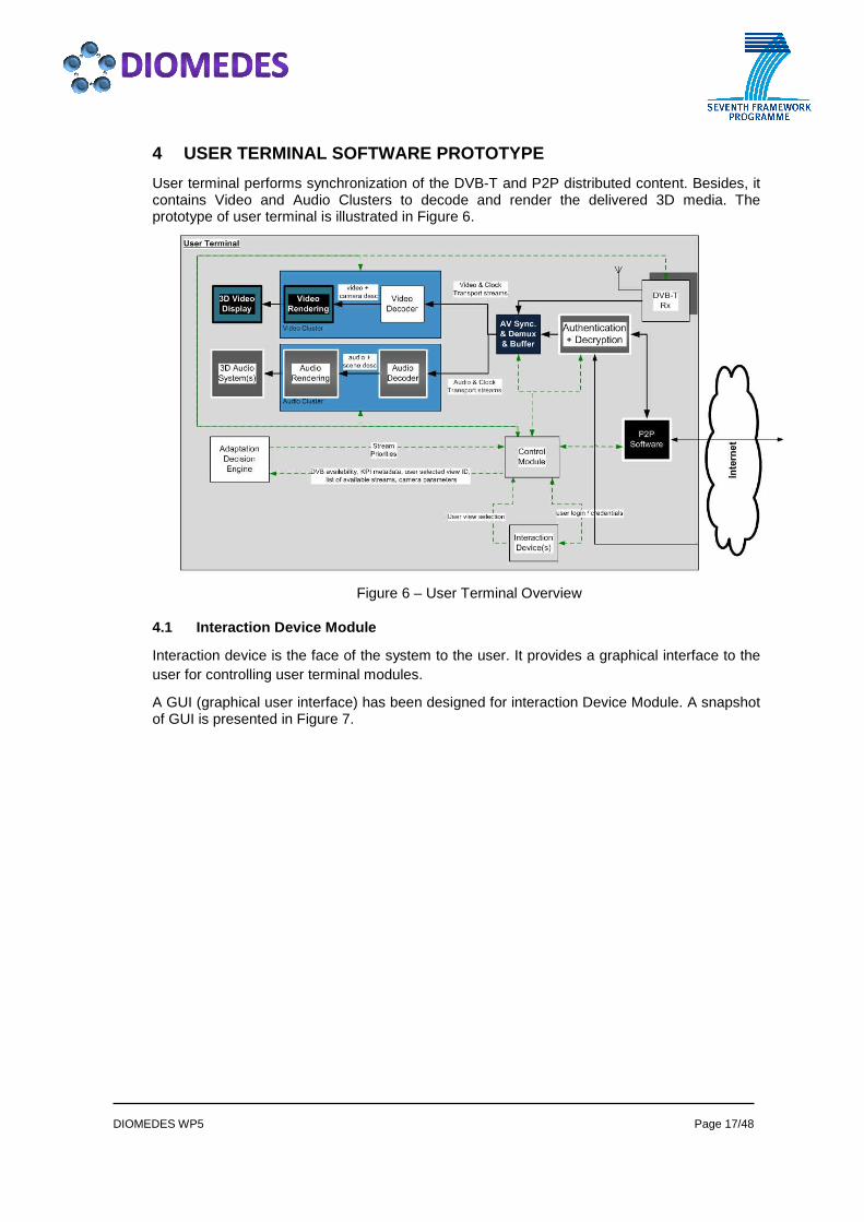
User terminal performs synchronization of the DVB-T and P2P distributed content. Besides, it contains Video and Audio Clusters to decode and render the delivered 3D media. The prototype of user terminal is illustrated in Figure 6.
Figure 6 – User Terminal Overview
4.1 Interaction Device Module
Interaction device is the face of the system to the user. It provides a graphical interface to the user for controlling user terminal modules.
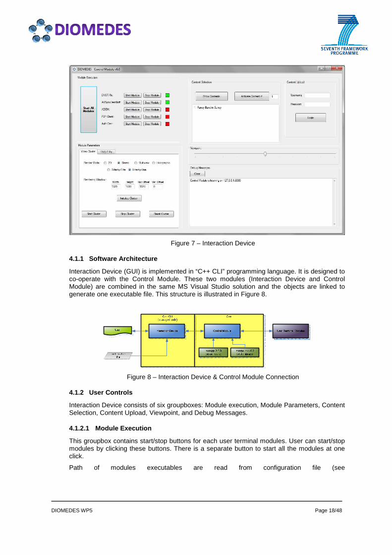
A GUI (graphical user interface) has been designed for interaction Device Module. A snapshot of GUI is presented in Figure 7.
DIOMEDES WP5 Page 18/48
Figure 7 – Interaction Device
4.1.1 Software Architecture
Interaction Device (GUI) is implemented in “C++ CLI” programming language. It is designed to co-operate with the Control Module. These two modules (Interaction Device and Control Module) are combined in the same MS Visual Studio solution and the objects are linked to generate one executable file. This structure is illustrated in Figure 8.
Figure 8 – Interaction Device & Control Module Connection
4.1.2 User Controls
Interaction Device consists of six groupboxes: Module execution, Module Parameters, Content Selection, Content Upload, Viewpoint, and Debug Messages.
4.1.2.1 Module Execution
This groupbox contains start/stop buttons for each user terminal modules. User can start/stop modules by clicking these buttons. There is a separate button to start all the modules at one click.
Path of modules executables are read from configuration file (see

DIOMEDES WP5 Page 19/48
APPENDIX C: Control Module – Configuration File).
A coloured box exists near start/stop buttons to indicate module status. If the module is started, this box becomes green. Otherwise, the box turns into red.
Figure 9 is a snapshot of a running system.
Figure 9 – Module Execution
4.1.2.2 Module Parameters
Module parameters are presented to user in “Module Parameters” tab (see Figure 7).
4.1.2.3 Content Selection
User has to start with content selection to initiate the system. By clicking “Show Contents” button, all the contents are retrieved from server and available contents are listed on Interaction Device. After selecting desired content, by clicking activate button to make system ready for content playbacking.
Figure 10 – Content Selection

DIOMEDES WP5 Page 20/48
4.1.2.4 Content Upload
In order to upload content to the Security Client Module, user shall login to system. This groupbox allows passing authentication information (ID, and password) to Security Client module. If user successfully logins to the system (authentication is done in Security Client Module and response is returned via Control Module), upload content menu appears. The user should select desired content via browse button and should specify a short description of the seleced content. After that, user clicks “Upload Content” and initiates uploading the content.
Figure 11 – User Login and Upload Content
4.1.2.5 Viewpoint
For free-viewpoint viewing feature, the interaction device facilitates a slide-bar to acquire the user's selection of the desired viewpoint / viewing angle in the units the Audio & Video Clusters can interpret as can be seen on Figure 7.
Minimum and maximum values are content specific and are obtained from content metadata.
4.1.2.6 Debug Messages
For debugging purposes, all the incoming and outgoing JSON messages from/to Control Module are printed on the “Debug Messages” textbox (see Figure 7).
4.2 Control Module
Control Module is the linkage between Interaction Device Module and all other user terminal modules (see Figure 6). It sends control commands, receives system status, and delivers user preferences and dynamic parameter changes. All these operations are transmitted through JSON messages as stated in D5.1. For complete set of incoming/outgoing JSON messages see APPENDIX A, and APPENDIX B.
Control Module is implemented in C++ programming language. Externally, it uses json-cpp and jsonrpc-cpp libraries (see Figure 8).
Control Module communicates with all the other modules inside user terminal in asynchronous way. Therefore there is too much communication overhead on Control Module. To overcome these kinds of potential communication problems, multithread server structure is used. Serving each request and forwarding them to the related modules controlled by different threads. So, sending and receiving messages are independent process.
There are two main processes in Control Module which could be named “Receiving” and “Sending”, and they are controlled by “Listener” and “Sender” threads concurrently. This mechanism is illustrated in Figure 12.

DIOMEDES WP5 Page 21/48
Figure 12 – Listener and Sender Thread block diagram
Listener Thread:
This thread is basicly a port listener process which listens to the Control Module port and catches incoming JSON messages that are sent from the other modules. Then, it forwards them into Control Module main system. After that, JSON message is parsed and become ready to be processed by Control Module system.
Sender Thread:
Sending mechanism is used to send JSON messages to other modules over Control Module. Sender thread gets JSON message and sends it to related target module without affecting other part of the Control Module system.
All incoming JSON messages shall be caught without missing any message and after implementing necessary operation in Control Module side, they shall be either routed correctly to the related modules or actions will be taken according to incoming message in Control Module side.
Because of using two different threads (for receiving and sending messages), there shall be communication interface between these processes. The bridge between two processes is provided by using “Queue” data structure. The logic behind the “Queue” structure can be described FIFO (First In First Out). First incoming messages will be processed firstly. Incoming message is being caught by Listener Thread and is inserted to the “Queue”. After inserting coming message into “Queue”, listener thread’s work finishes.
After inserting message into “Queue”, Sender Thread realizes that “Queue” is not empty and there is a message to send. Then, sending mechanism will send message according to the parameters which are included in the message itself.

DIOMEDES WP5 Page 22/48
Remove Message from
Queue
Prepare
Message
to send
Parse Message
Listerner
Thread
Sender
Thread
Incoming Message
Get Message
Insert Message
Get Message
QueuePort Listening
MessageSend Message
To Related Module
Other
Modules
Figure 13 – Listener and Sender mechanism
4.3 Adaptation Decision Engine Module
Adaptation Decision Engine Module (ADEM) is a module for deciding the media stream priorities, which are used by the P2P Module and Video Cluster for performing their respective content adaptation operations. Based on the initial content metadata, KPI metadata and context changes information received from the Control Module, the ADEM makes adaptation decisions and feeds back the decisions in JSON messages to the Control Module.
ADEM is implemented in C++ and uses JSON-cpp and JSONRPC-cpp static libraries. Multi-threads technique is also used in message processing and exchanging in order to improve processing efficiency and potential communication blocking problems.
4.3.1 Message-driven Adaptation Decision Making
Upon receiving any messages listed as following from the Control Module, the ADEM will run the adaption algorithm and prioritise the media stream list.
• Content Metadata message
• Video KPI Metadata message
• User Requested View message
• DVB Availability message
The adaptation decision is a View Priority list message, which is sent to the Control Module for further forwarding to other concerned modules. All messages are defined in D5.1 and the adaptation decision algorithm is described in D3.5.
The main adaptation process is run in a thread which is responsible to queue and parse all received messages. If a new adaptation decision, which is a View Priority list JSON message, is made, the main thread will create and fire a new thread to send out this message. In this way, the main thread will not be blocked by other unexpected events out of the control of the ADEM. This process is illustrated in Figure 14.

DIOMEDES WP5 Page 23/48
Figure 14 – Message-driven adaptation decision making mechanism
4.3.2 Module Configuration and Features
The ADEM IP address and JSON RPC server TCP port number can be configured in the “DiomedesConfig.ini” file. This configuration file is in a JSON message format so that all parameters are easily readable. If the ADEM is running on the same computer as the Control Module, its IP address should be set to the local host address, i.e “127.0.0.1”. The JSON RPC server TCP port is set to 8000.
The configuration file should be put in the same directory as the ADEM executable file.
4.3.3 Running and Debugging ADEM
The ADEM is run without any command options. For example:
• start the ADEM with all the debug information displayed on the standard console or screen
“adaptDecisionEngine.exe”
• start the ADEM with all the debug information redirected to a log file named “logfile.txt”
“adaptDecisionEngine.exe > logfile.txt”
• start the ADEM and all the debug information is redirected the NUL device, which means no debug information is recorded in anyway.
“adaptDecisionEngine.exe > NUL”
The debug information includes all messages the ADEM transmitted and received from the Control Module. This is useful in the debug and integration with other modules.
4.4 DVB-T Receiving Module
The DVB-T Receiving Module uses a Dektec DVB-T Demodulator card to receive the modulated DVB-T signal and sends the contained transport stream via UDP/IP protocol to the AV-Sync Module.
This module is entirely written in C++ language. It uses the following C++ libraries: the Dektec API, Boost 1.46.1, JsonCpp 0.6.0 and JsonRpc-Cpp 0.3.

DIOMEDES WP5 Page 24/48
Interfacing with other modules
This module communicates via JSON-RPC only with the Control Module. It receives control messages and sends notifications. The communication is handled synchronously, strictly sequentially to prevent inconsistent system state.
The output MPEG2 transport stream data is streamed to the AV-Sync Module at constant bitrate. The output bitrate is directly derived from the input bitrate based on the demodulator hardware clock.
Operation modes
The DVB-T Receiver Module can be used in two ways. The normal operation mode is using the demodulator card and transmitting the received stream via UDP/IP. The test mode can be used if no real demodulator hardware is present. In this mode a transport stream file is streamed with the bitrate detected from the present timestamps. This is useful for testing other module (chains) without setting up the real DVB transmission chain.
Software architecture
The software consists of two components: The logic responsible for handling the transport stream reception, processing and output is implemented in a dynamic link library (DLL). The JSON communication is implemented in an executable (EXE) that makes use of the DLL.
Transport stream processing library
The implementation for processing the transport streams is multithreaded. The basic processing is done using two threads: one for data input and one for data output. Additionally there is one thread for monitoring the received signal. During the reception of the transport stream it is also parsed. This parsing is done to detect if the stream is 2D or 3D stereo and to extract the content reference (for the P2P system). Parsing is done according to the so called lazy initialisation scheme to keep computational cost minimal. This means it is only done when really necessary and only required information is parsed. To achieve a DVB standard compliant output stream the hardware clock of the demodulator card is used for the correct timing of the output thread. The packets are time-stamped by the demodulator card on arrival and transmitted according to this time information plus an adjustable processing delay (depending on the incoming bit-rate, typically < 1 frame).
JSON communication interface
The communication messages and notifications between the DVB-T Receiver Module and the Control Module are handled in a console application. The application invokes the functions of the transport stream processing library according to JSON-RPC messages received from the Control Module. This is done strictly sequentially to prevent inconsistent system states caused by conflicting commands. Notification events raised by the transport stream processing library are translated into JSON-RPC notifications and sent to the Control Module. Please refer to Appendix A and B for further information regarding the available messages and notifications.
Software dependencies
The module is running on Windows 7 OS with two dependencies. The first dependency is Visual C++ 2010 Runtime and the second dependency is the Dektec demodulator card DTA-2135 with the corresponding drivers installed (Dektec components are not required when using testing mode).
4.5 AV Sync. & Demux & Buffer Module
4.5.1 Overview
The Av Sync & Demux & Buffer Module is responsible for:
� Demultiplexing the transport stream arriving from DVB-T and P2P paths to separate

DIOMEDES WP5 Page 25/48
buffers of video and audio.
� Buffering audio streams and video-layer streams (layers for the video-viewpoints).
� Holding several seconds of data (transport packets) before streaming it to the relevant cluster.
� Synchronising the audio and the video, the streams of the video views, the streams arriving from DVB-T and P2P.
� Sending the synchronised streams to the Video Cluster & Audio Cluster some frames before the indicated presentation time in order to allow the decoders enough time to decode and wait till it is time to send the frame for rendering.
The module is implemented in C++ for real-time performance. The configuration interface uses JSON-RPC over TCP and implemented using JSON-cpp and JSONRPC-cpp static libraries. The module is built as a process, as decided in the DIOMEDES architecture, to allow maximal decoupling between modules and to in order to be able to execute them on different machines.
4.5.2 Interfaces
These are the input and output interfaces:
Inputs:
� From P2P: multiple single-program transport streams. For each video view: base-layer stream, enhancement-layer stream, and depth-map stream. In addition there are 1 or more audio streams. In case of network congestions, the enhancement-layer and the depth-map may not be available.
� From DVB-T: single-program transport stream, containing:
o Single\two video PIDs carrying single\stereoscopic view
o Audio PIDs
o PCR information (separate PID or carried with the video)
Outputs:
� Multiple single-program transport streams with PID per video stream (base, enhancement, depth) + PCR PID will be sent to the Video Cluster.
� Audio TS stream + PCR PID will be sent to the Audio Cluster.
� Optional: PCR clock (with the TS wrapping) will be sent to both clusters using UDP/IP Multicast. Motivation: to compensate for a possible difference in the update-time of the Video and Audio Clusters.
4.5.3 Building Blocks

DIOMEDES WP5 Page 26/48
Figure 15 – AvSync block diagram
These are the building blocks of the AvSync and their roles:
� Network Handler : gets input of UDP packets that compose TS streams from the DVB-T and P2P (arriving from other modules). All the TS packets that we get are complete 188 TS packets (7 TS packets in one UDP). Port configuration is static and can be changed in a configuration file. All P2P streams arrive to the same input port. The output if passed to the Demux blocks.
� Demux : gets the input stream from the DVB-T. It auto-detects the streams according to the PAT \ PMT. It separates the stream to video and audio packets and to different PIDs and sends the TS packets to the relevant buffer (buffer per PID). New PMT is generated, containing all the streams from both DVB-T and from P2P. The DVB-T PCR is passed as a reference PCR to the PCR PLL.
� Demux Fixed PID : same as the Demux, but without auto-detection, since P2P streams does not contain PMT. It uses the content-metadata message to know what PIDs to demultiplex to the video or to the audio buffers. It gets the input streams from the P2P.
� Buffers: support thread protected data container for input and output of TS packets. Control buffer levels and send notifications about the buffer state and about passing thresholds of overflow \ underflow. Uses flow-control to decide when to output data.
� Buffer Manager: container of all the buffers. Decides to initially start the process of sending data when buffers have enough data. Add PAT\PMT packets to the buffers in order to send them to the clusters. Send clear command to the buffer when loop is detected. Scan all buffers for debugging purposes.
� Flow Control: contained in every buffer. It gets data from the buffer about input and output of packets and about the timing info (PCR and DTS), and decides when it is time to send out data from the buffer.
� Sync & Transmit : periodically sends the relevant data from the buffers to the clusters. Data is polled out according to the PCR time. It also sends the generated PCR PID packets used for synchronisation in the clusters.
� PCR PLL : creates PCR from the internal clock. The PCR is fixed according to the reference PCR that arrives with the DVB-T stream. It also detects PCR loops and

DIOMEDES WP5 Page 27/48
handles them. � TS Generator : generates the PCR TS packets and PMT packets.
� Configuration : contains JSON Listener to get configuration updates (e.g. the content metadata) and JSON Sender to send module status that is required by other modules (e.g. buffer state and the current PCR). In addition, there are other configuration settings in a configuration file (e.g. buffer size in seconds, destination of Audio & Video Clusters).
4.6 Audio Cluster
The Audio Cluster Module receives the audio transport streams and adaptation control data from the terminal Control Module. The transport stream is decoded and used for synchronisation to the transmitted timestamps. The audio rendering modules drive the loudspeaker system used for reproduction of the programme’s audio scenes. The Audio Cluster prototypes run on Linux based PC systems that are equipped with the necessary audio interface hardware modules. Several different PC systems were used during development, driving loudspeaker systems of different complexity (loudspeaker number). The following sections describe the demonstrator prototype that is used as the final instance of the Audio Cluster.
4.6.1 Hardware Platform
- PC Intel Core 2 Quad Q9550, 2.8 GHz (Mini-PC)
- RAM 4GB
- Audio interface: RME HDESP MADI (64 channels I/O)
4.6.2 Software Environment
- Operating System: Linux 2.6 with X11 / KDE User Interface
- All Audio Cluster software modules run within a modular multi-threading software framework
- XML configuration file determines running modules, their parameters and interconnections
4.6.3 Development Encironment
- GCC (GNU Compiler Collection), C++ compiler
4.6.4 Internal Audio Cluster Modules (for DIOMEDES terminal use)
The following modules have been implemented for the DIOMEDES architecture.
i) MPEG-2 Transport Stream Decoder Module
- listens on UDP port for incoming TS packets
- conducts audio & scene decoding, clock recovery and audio sample rate conversion.
- performs priority decision (channel adaptation) in the case of multiple incoming streams
- supports DIOMEDES object based audio scene format
- supports established audio stream formats: MPEG-1 Layer 2, MPEG-1 Layer
DIOMEDES WP5 Page 28/48
3, AC-3
ii) Audio Scene Scaling Module
- performs scene adaptation to different reproduction system layouts and viewpoint changes
- scaling parameters can be controlled by external modules via OSC control protocol
iii) JSON-RPC Module
- JSON-RPC parsing of viewpoint messages
- Controls the Audio Scene Scaling Module sending OSC messages
iv) Driving Coefficient Calculation Module
- different variants, including Wave field synthesis, low resolution rendering, 3D rendering
- implementation options for dedicated scene adaptation processing related to display/listener setups
- receives object/scene description data
- based on configuration data set describing the reproduction system (loudspeaker setup)
- sends driving coefficients to external modules
v) Dynamic Filtering Module
- performs frequency response compensation based on incoming driving coefficients, depends on current object/scene description
- performs real-time FIR filter design (computational expensive)
- conducts fast multichannel-convolution
vi) “Convolver” Module
- performs matrix signal processing: interpolated level and delay line matrix
- generation of loudspeaker signals by processing the incoming audio object’s signals
vii) Object Based Scene Coder Module
- not used in DIOMEDES terminal but during audio stream generation
- realtime coding of object based audio scenes based on incoming audio signal and scene description streams
These modules are arranged in a processing graph with the following functional structure:

DIOMEDES WP5 Page 29/48
Figure 16 – Main parts of the internal structure of the Audio Cluster
(from D2.3: Final reference system architecture)
For detailed information about the Spatial Audio Decoder Module and coding format, please refer to D4.4 – Report on the developed audio and video codecs.
For detailed information about the rendering and coefficient calculation modules, please refer to D3.5.
The JSON viewpoint control message format is shown in Appendix: “Output JSON Messages”
Within the DIOMEDES architecture, the JSON Module and MPEG-2 TS (Spatial Audio) Decoder Module are the only interfaces to the other DIOMEDES clusters.
The Audio Cluster’s software framework is started as a command line executable.
4.7 Video Cluster
4.7.1 Decoder Control Module
The Decoder Control Module is responsible for controlling different functional modules within the Video Cluster. Besides, it interfaces with the Control Module for user interaction. It accepts user commands from the Control Module to start, stop and reset the video decoders, to instruct the EsDemux Module to demultiplex ES streams and to send to specified decoders, and also to set the Video Renderer channels and models for rendering the video streams properly. All communications with other modules, namely the Control Module, the EsDemux Module, the Video Decoders and the Video Renderer, are in JSON messages with JSON RPC protocol. The module itself is implemented in C++.
To start the Video Cluster, the Control Module will first try to initialise the Video Cluster with an initialisation message. Upon receiving this message, the decoder Control Module sends the channel configuration and rendering model messages to the Video Renderer. It also use the initialisation information (video stream PIDs) to instruct the EsDemux Module to demultiplex the incoming video streams and where the streams are sent to. When a Video Cluster “start” command is received, the Video Decoder will start the Video Decoders with a “StartDecoder” message. Information such as on which UDP port the decoder should expect stream data, and what data exchanging mode the Renderer is using, etc., are included in the message.
As KPI metadata is embedded in the video streams, the Video Decoders will have to decode the KPI metadata and send them to the decoder Control Module in the format of JSON message. The KPI metadata is needed for the ADEM to make adaptation decisions. Therefore, the Decoder Control Module is obliged to forward all KPI metadata messages to the Control Module and from there the messages are further forwarded to the ADEM.
User requested views from the Control Module will affect the work of Video Cluster, because the requested views could be different with the previous one. In this case, the requested views will be forwarded to the Renderer.

DIOMEDES WP5 Page 30/48
4.7.1.1 Module Architecture
The high-level architecture of the decoder Control Module is illustrated in Figure 17.
Init MsgStart/Stop/Reset
User Req. View
KPI Msg 0
KPI Msg N
Start/S
top/Re
st 0
KPI Msg 1Sta
rt/Stop/Re
st 1
Start/S
top/Re
st N
Demux PID
s Msg
Channel ConfigRenderer Mode
Figure 17 – Decoder Control Module block diagram
For more information about the message exchanges between the related modules, please refer to deliverable D5.1.
4.7.1.2 JSON messages
The Decoder Control Module accepts the following messages:
• Video decoder initialisation message from Control Module,
• Video decoder start, stop and reset messages from Control Module,
• User requested viewpoint from Control Module,
• KPI metadata messages from Video Decoders.
The Decoder Control Module sends out the following messages to other modules:
• Video decoder start, stop and reset messages to all Video Decoders,
• User requested viewpoint message to the Video Renderer,
• KPI metadata messages to the Control Module,
• Channel input configuration message to the Video Renderer,
• Output configuration message to the Video Renderer,
• User requested PIDs message to the EsDemux Module
All messages are defined in deliverable D5.1 and D3.5.
4.7.1.3 Module configuration and features
The Decoder Control Module IP address and the JSON RPC server TCP port number can be configured in the “DiomedesConfig.ini” file. This configuration file is in a JSON message format so that all parameters are easily readable. If the Decoder Control Module is running on the same computer as the Control Module and the Video Decoder, its IP address should be set to the local host address, i.e “127.0.0.1”. Otherwise it should be set to the network interface’s IP address from which the JSON messages are transmitted and received. The JSON RPC server TCP port is set to 8002.

DIOMEDES WP5 Page 31/48
The configuration file should be put in the same directory as the Decoder Control Module executable file.
Other parameters which are used by the Decoder Control Module are also defined in the configuration file. They are the Control Module IP and JSON port, EsDemux IP and JSON port, Video Decoder IP and JSON port, Video Renderer IP and JSON port, respectively.
The current version of decoder control has features which can be enabled or disabled according to the system configuration and other modules’ capabilities. The following features are supported:
• JSON_TO_VDECODER: a switch to enable/disable the Decoder Control Module to send JSON messages to the Video Decoders.
• JSON_TO_RENDERER: a switch to enable/disable the Decoder Control Module to send JSON messages to the Video Renderer.
• STATIC_PID: a switch to enable/disable the Decoder Control Module to use a pre-configured view PID list or use the PID information from Control Module JSON messages.
All these features make the Decoder Control Module very flexible to different system and module configurations. It has been proved very useful during the development of Video Cluster and system integration.
4.7.1.4 Running and debugging the Decoder Control M odule
To run the Decoder Control Module, users need to run the following command lines:
• To see all debug information on the standard console or screen
decoderControl.exe
• To redirect all debug information to a file named logfile.txt
decoderControl.exe > logfile.txt
• To conceal all debug information, i.e. to redirect the debug information to a NULL device and make no output
decoderControl.exe > NULL
The debug information includes all received JSON messages, transmitted JSON messages, message parsing information, running status of the JSON RPC server, and general module status report. It is very comprehensive for running the module. Users can rely on this information to assist running the module smoothly.
4.7.2 ES Demultiplexing Module
The ES demultiplexing (EsDemux) Module is responsible for demultiplexing video transport streams for the Video Cluster. It receives TS video stream from the AvSync Module and demultiplex it into different video elementary streams according to the user’s requested view PIDs. The demultiplexed streams are then transmitted to different Video Decoders in a way such that the video base layer and depth map will use two consecutive decoders. The video enhancement layer data will be transmitted to the same decoder as its base layer. Besides this, the EsDemux also gets the PCR clock reference information from the TS stream and send the PCR to the Video Renderer in a JSON message.
4.7.2.1 Module Architecture
EsDemux Module is comprised of three sub-modules, the JSON RPC server sub-module, the TsNetwork sub-module and the Ts2Pes sub-module. These sub-modules are run concurrently

DIOMEDES WP5 Page 32/48
in different threads. The JSON RPC server sub-module is responsible for processing the JSON messages from Decoder Control Module and extracting the PID information for demultiplexing. The TsNetwork sub-module, which is run from a different thread, receives all TS packets from the AvSync and puts them into a circular buffer. When sufficient TS packets are accumulated in the circular buffer and not demultilexed, the circular buffer will be full. In this case, newly arrived packet will overwrite and replace the most obsoleted packet. A circular buffer is adequate for this purpose, because if the video data in the buffer is too old, there is no need to keep and demultiplex it in a live streaming scenario. The Ts2Pes demultiplexing sub-module is invoked in another concurrent thread by the main EsDemux Module whenever a user-requested-view PID message is received from the Decoder Control Module. It reads data packets from the circular buffer, demultiplexs the packets according to the requested PIDs, and transmits the demultiplexed video data – base layer, enhancement layer and/or depth map – to the designated Video Decoders. The architecture of the EsDemux Module is shown in Figure 18.
CircularBuffer
JSON RPC
Server
Ts2Pes
Thread
TS Data
Tx Buffer
PES Data
Data to Decoder 0
Data to Decoder 1
Data to Decoder 2
Data to Decoder N
Create Thread Ts2PesCreate TsNetwork Thread
JSON Msg from
DecoderControl
PCR Msg to Renderer
EsDemux Module
Figure 18 – EsDemux Module functional diagram
4.7.2.2 JSON messages
The main thread which runs the JSON RPC server in the EsDemux Module accepts demultiplexing instructions, which is a user-requested-PIDs JSON message, from the Decoder Control Module only. The message includes information such as which PIDs needs to be demultiplexed from the incoming video transport stream from AvSync. During the stream demultiplexing, the PCR information is also extracted from a default PID, which is dedicated to PCR transmission. The PCR information is wrapped into a JSON message and sent to the Video Renderer. Therefore, the EsDemux deals with two JSON messages as following.
• User requested view PIDs message from Decoder Control Module,
• PCR – program clock reference – message to Video Renderer.
The details of these messages are defined in deliverable D5.1.
4.7.2.3 Module configuration and features
The EsDemux Module IP address and JSON RPC server TCP port number can be configured in the “DiomedesConfig.ini” file. This configuration file is in a JSON message format so that all

DIOMEDES WP5 Page 33/48
parameters are easily readable. If the EsDemux Module is running on the same computer as the the Video Decoder, its IP address should be set to the local host address, i.e “127.0.0.1”. Otherwise it should be set to the network interface’s IP address from which the JSON messages are expected to be transmitted and received. The EsDemux Module’s JSON RPC server TCP port is set to 8001. The EsDemux uses UDP port 8009 to receive all the TS stream packets.
The configuration file should be put in the same directory as the EsDemux Module executable file.
Some other parameters which are used by the EsDemux Module are also defined in the configuration file. They are the Decoder Control Module IP and JSON port, Video Decoder’s base IP, JSON port and data port, Video Renderer IP and JSON port, respectively. Note that for all Video Decoders, only the base IP and JSON/data port of the first Video Decoder are defined, because it is decided that in Diomedes Video Decoders use consecutive IPs and TCP/UDP port number.
The current version of EsDemux Module has features which can be enabled or disabled according to the system configuration and other modules’ capabilities. The following features are supported:
• JSON_TO_VDECODER: a switch to enable/disable the EsDemux Module to send JSON messages to Video Decoders.
• JSON_TO_RENDERER: a switch to enable/disable the EsDemux Module to send PCR JSON messages to the Video Renderer.
• STATIC_PID: a switch to enable/disable the EsDemux Module to use a pre-configured view PID list or use the PID information from Decoder Control Module.
All these features make the EsDemux Module very flexible to different system and module configurations. It has been proved very useful during the development of Video Cluster and the in integration.
4.7.2.4 Running and debug the Decoder Control Modul e
To run the EsDemux Module, users need to run the following command lines:
• To see all debug information on the standard console or screen
esDemux.exe
• To redirect all debug information to a file named logfile.txt
esDemux.exe > logfile.txt
• To conceal all debug information, i.e. to redirect the debug information to a NULL device and make no output
esDemux.exe > NULL
The Ts2Pes sub-module can be used independently for demultiplexing TS streams. To use it independently, users need to run the following command lines:
TStoPES.exe –v –pid <number_of_PIDs> [b|e|d] <PID#1> p <UDP_port#1> …
[b|e|d] <PID#N> p <UDP_port#N>
The TStoPES.exe command line options are explained as following:
• -v: verbose on
• -pid <number_of_PIDs>: enter total number of PID in the stream, e.g. -pid 3
• [b|e|d] <PID#x]: indicate what type of video data in stream PID#x. Note that If there is enhancement layer for a specified base layer, the enhancement layer PID should be

DIOMEDES WP5 Page 34/48
after the base layer PID immediately, e.g. “ b 4113 e 4114” where the base layer is PID 4113 and enhancement layer is PID 4114.
“b”: base layer,
“e”: enhancement layer,
“d”: depth map
• p <UDP_port#N>: to send the video packets to UDP port #N. The Video Decoder should listen on this port for receiving video stream.
For example, if view #1 includes base layer PID 4113 and enhancement layer PID 4114, view #2 includes only base layer PID 4115, and the view data are sent to UDP port 4000 and 4001 respectively, the command line to demultiplex this stream would be as following:
TStoPES.exe –v –pid 3 b 4113 e 4114 p 4000 b 4115 p 4001
Without redirect the output of the Ts2Pes module, it will output all the debug information to the standard console. Users can redirect the debug output information to a file or to the NULL device to improve the performance.
4.7.2.5 Debug Information
The EsDemux Module outputs rich debug information including all JSON messages it processed and the details of all video packets it parsed. The debug information is writen to a local file “logFile.txt”. Figure 19 is a snapshot of the output of the log file.
Figure 19 – Snapshot of EsDemux Module log file
The Ts2Pes module also write all demultiplexed streams into a local file named as “xxxx_correct.264”, where “xxxx” is the PID number of the stream, This file can be used to compare with the data received by Video Decoders for verification.
4.7.3 Video Decoder
4.7.3.1 Module Architecture
Video decoder has three responsibilities:
1. Receiving elementary with stream with PTS timestamp and KPI messages from the ES Demux Module.

DIOMEDES WP5 Page 35/48
2. Forwarding raw images to the Video Renderer with PTS information
3. Forwarding KPI messages to the Adaptation Decision Engine Module
The NAL Units are stored in a queue that is shared with the networking and decoding threads. As new NAL Units arrive from the UDP socket, the decoding thread starts to generate raw images. These images are forwarded to the Video Renderer. While storing the NAL Units, the networking thread also extracts the KPI information and forwards it to the Adaptation Decision Engine Module.
4.7.3.2 Command Line Options
The command line options when running the executable are as follows:
-forwardWithTCP TCP port number to send raw images (if not
set, send by shared memory)
-h264 input filename for local test
-layer layer number to decode
-o name of the output yuv file to store
-rendererIP IP address of the Video Renderer
-rendererPort port to Video Renderer for JSON messages
-udp UDP port number
-viewID view ID of the incoming stream
Table 1 – Command Line Options of the Video Decoder
4.7.4 Video Rendeder
The Video Renderer is the component at the end of the Video Cluster, directly connected to the viewer’s 3D display. Because user controls are implemented in different modules, the module is implemented as a C++/OpenGL command line executable. It communicates with other modules via command line options, network connections, and shared memory connections, while the output of the module appears on the DVI/HDMI connection of the renderer PC.
The rendering / view generation algorithms used in the Video Renderer are described in detail in Deliverable D3.5 – Report on 3D Video/Audio rendering and content adaptation, and thus omitted from this document.
4.7.4.1 Module Architecture
The high-level architecture of the module is illustrated on the following block diagram.

DIOMEDES WP5 Page 36/48
Figure 20 – Main components of the Video Renderer
4.7.4.2 Command line options
In early versions of the Renderer, data sources, rendering modes and the layout of the output screen have been defined on the command line. Example:
diomedesRenderer null null 1280 0 1920 1080 sbs
(for running the Renderer in stereo side-by-side mode on the secondary monitor, full HD resolution, with 2 shared memory inputs from the decoder)
Today there are only two command line options, as all of parameters can be changed on the fly via JSON messages. These two parameters are: port number and verbosity level. Port number is the port on wich all of the communication will go through. Verbosity mode can be a number from 0 to 6, determining the level of filtering applied to error/warning/informational messages on the console output. Default values are available for both, so the executable can be run without any parameters. Examples:
“diomedesRenderer 12345 5” starts the Video Renderer listening on the 12345 port on all of the available network adapters with printing almost everything on the output.
“diomedesRenderer 12345” starts the Video Renderer listening the same mode, but with minimal verbosity.
“diomedesRenderer” or double click starts the Video Renderer to listen on the default DIOMEDES-reserved port: 8086, and minimal output.
4.7.4.3 JSON Messages
The JSON messages accepted by the Video Renderer are the following:
• PCR sync message (34)

DIOMEDES WP5 Page 37/48
• Channel init message (40 init)
• Frame arrive message (40)
• Channel close message (40 close)
• Input configuration message (50)
o All of the available views listed
o Description of cameras, if P2P alive
• Output configuration message (51)
o Display type and window position
o List of requested Direct displayed and generated views
• Viewpoint modification message (52)
o Requested view ID only, all other necessary parameters are automatically calculated from this number, based on the input View IDs and input camera descriptions configured in [50]
For more detailed information about the content of these messages, please refer to D3.5 - Report on 3D Video/Audio rendering and content adaptation.
4.7.4.4 Keyboard shortcuts
Shortcuts are available to test the chain without some modules, or the Video Renderer standalone, they are mostly used for debugging, and not necessary in normal use cases, as the user interacts with the system via a dedicated user interface.
• SPACE – play / pause timer, if no sync signal available
• 1 – switch OFF / ON synchronisation to the internal clock
• 5 – Show first and second views of last configuration colour coded (RED-CYAN) 5-9 does not modify window size or position, 5-8 does not modify requested output views (even if MVD-DBR)
• 6 – Show first and second views of last configuration side by side
• 7 – Show first and second views of last configuration line interleaved
• 8 – Show first view of last configuration alone
• 9 – Show all of the available input views in multi view side by side mode ordered by channel ID
• u – Displays debug info on the screen about generated views
• I – Displays Input debug info on the screen
• o – Displays render mode on the screen
• p – Displays PCR and timer status on the screen
• f – Forced re-decode for incoming YUV raw data for measuring FPS, with paused clock, this mode is equivalent with infinite input bandwidth
4.7.4.5 Interfaces Between Video Decoder and Video Renderer
Shared memory and TCP connections are implemented. On a local computer it is recommended to use shared memory, to avoid the operating system’s TCP handing overhead.

DIOMEDES WP5 Page 38/48
These two modes can be freely combined.
4.7.4.6 Debugging interface
The Video Renderer has been equipped with a debugging interface to ease finding errors during integration. This interface shows the properties of the incoming streams, buffers, Channel and View IDs, timer status, rendering performance, output mode description, and internal state of MVD-DBR config, camera information, requested viewpoints or direct IDs, and any other information, that can be configured with the JSON interfaces.
Figure 21 – Debugging screen of the Video Renderer

DIOMEDES WP5 Page 39/48
5 CONCLUSIONS
This deliverable describes the software prototypes of all modules (on the server and on the user terminal side) within DIOMEDES system. Modules are described in software point of view: building blocks and mechanisms are defined, block diagrams are illustrated, execution steps are specified, command line options (if available) are described . The input of this deliverable comes mainly from deliverables D2.1 – User Requirements and Initial reference system architecture report and D5.2 – Report on proof of concept prototypes. More detailed information for all components can be found in the related deliverables.

DIOMEDES WP5 Page 40/48
APPENDIX A: CONTROL MODULE – INPUT JSON MESSAGES
Control Module - Input Messages
Parameter Description
Source Module JSON Message
JSON Message
Period
Final Comment & Rationale
AV Sync PCR
AV Sync&Demux&Buffer Module
{ "id":0, "jsonrpc":"2.0", "method":"AvSync_PCR", "params": { "connNumber":27, "PCR": 1234 } }
every second
AV Sync Buffer Status
AV Sync&Demux&Buffer Module
{ "id":0, "jsonrpc":"2.0", "method":"BufferState", "params": { "connNumber":27, "PID": 4113, "Fullness": 82, "FreeKB": 4500, "State": "Overrun" } }
every half a second
Availability of DVB Input
DVB-T2 Rx Module
{ "id":0, "jsonrpc":"2.0", "method":"AvailabilityOfDVB", "params": { "connNumber":5, "DVBStatus": 1 } }
when DVB status changes
“0” means not available, “1” means available
Mode of DVB Input
DVB-T2 Rx Module
{ "id":0, "jsonrpc":"2.0", "method":"ModeOfDVB", "params": { "connNumber":5, "DVBMode": 0 } }
when DVB mode changes
“0” means single view, “1” means stereo. It is known by the system that if mono-view is
streamed over DVB-T, this is always the left
view of the stereo-pair
KPI metadata for QoE (e.g., depth perception KPI, image quality KPI)
Decoder Control Module
{ "id": 3901, "jsonrpc": "2.0", "method": "VideoKPI", "params": { "ConnNumber": 39, "PID": [4113, 4114], "image_quality": [35, 36], "depth_perception": [63, 64] } }
one GOP (~ around half a
second)
KPI metadata is prepared offline for the encoded media, and video related KPI is carried in the compressed bit-stream. Therefore, KPI values are recovered in the video decoder module.
View Priority List (Ranking List)
Adapt. Decision Engine Module
{ "id" : 601, "jsonrpc": "2.0", "method" : "ViewPriority", "params" : { "ConnNumber" : 6, "Layer Priority Order" : [ "b", "d", "b", "d", "b", "d", "e", "e", "e" ], "PID Priority Order" : [ 4118, 4220, 4115, 4117, 4221, 4223, 4119, 4116, 4222 ], "Priority Order" : [ 1, 2, 3, 3, 4, 4, 5, 6, 7 ], "View Priority Order" : [ 1, 0, 2 ] } }
whenever ranking is changed

DIOMEDES WP5 Page 41/48
APPENDIX B: CONTROL MODULE – OUTPUT JSON MESSAGES
Control Module - Output Messages
Parameter Description
Destination
Module JSON Message
JSON Message
Period
Final Comment & Rationale
DVB Start DVB Receiver Module
{ "id":0, "jsonrpc":"2.0", "method":"DVBRxStart", "params": { "connNumber":7 } }
when user clicks the
"Start" button on "DVB-T Rx"
tab on Interaction
Device
DVB Stop DVB Receiver Module
{ "id":0, "jsonrpc":"2.0", "method":"DVBRxStop", "params": { "connNumber":7 } }
when user clicks the
"Stop" button on "DVB-T Rx"
tab on Interaction
Device
DVB Switch Channel
DVB Receiver Module
{ "id":0, "jsonrpc":"2.0", "method":"DVBRxTune", "params": { "connNumber":7, "channel":"2" } }
when user clicks the
"Switch" button on "DVB-T Rx"
tab on Interaction
Device
DVB Get SNR
DVB Receiver Module
{ "id":0, "jsonrpc":"2.0", "method":"DVBRxGetSnr", "params": { "connNumber":7 } } return message is: { "id":0, "jsonrpc":"2.0", "result":-20 }
when user clicks the
"Update" button on "DVB-T Rx"
tab on Interaction
Device
SNR value is get from return message.
PCR P2P Client Module
{ "id":0, "jsonrpc":"2.0", "method":"AvSync_PCR", "params": { "connNumber":8, "PCR": 1234 } }
every second
AV Sync Buffer Status
P2P Client Module
{ "id":0, "jsonrpc":"2.0", "method":"BufferState", "params": { "connNumber":8, "PID": 4113, "Fullness": 82, "FreeKB": 4500, "State": "Overrun" } }
every half a second

DIOMEDES WP5 Page 42/48
Select Content
P2P Client Module
{ "id":0, "jsonrpc":"2.0", "method":"NotifyContentID", "params": { "connNumber":8, "ContentID": "2F2CCCEB-62DA-451F-9CAF-495DE9429F54", "MainSeedServerIp": "10.134.70.68" } } return message is: { "id":0, "jsonrpc":"2.0", "result":"true", "params":{ "Title": "Fancy Band in Surrey", "GUID": "2F2CCCEB-62DA-451F-9CAF-495DE9429F54", "SceneType": "Entertainment", "SceneSubType": "Music/Concert", "NumberOfViewpoints": 2, "ViewIDs": [0, 1], "LocationsFromOrigin": [0, 5.375], "layerPIDs": [4113, 4114, 4115]; "PIDtypes": ["b", "e", "b"], "VideoPIDsource": ["p2p", "p2p", "dvb"], "AudioNumberOfTracks": 2, "AudioStreamType": ["5.1", "5.1"], "AudioPIDs": [4352, 4353], "AudioPIDsource": ["dvb", "p2p", "p2p"], "CameraParam": [ {"Intrinsic": [906.529, 0, 624.000, 0, 906.529, 344.000, 0, 0, 1], "Extrinsic": [1, 0, 0, 0.2, 0, 1, 0, -0.0157962, 0, 0, 1, -0.0334732], "Near": 3857.570, "Far": 10072.544]}, {"Intrinsic": [906.529, 0, 624.000, 0, 906.529, 344.000, 0, 0, 1], "Extrinsic": [1, 0, 0, 0.4, 0, 1, 0, -0.0157962, 0, 0, 1, -0.0334732], "Near": 3857.570, "Far": 10072.544]} ], } }
When user selects the
content.
Content Metadata is passed to Control Module in return message.
View Priority List (Ranking List)
P2P Client Module
{ "id" : 601, "jsonrpc": "2.0", "method" : "ViewPriority", "params" : { "ConnNumber" : 8, "Layer Priority Order" : [ "b", "d", "b", "d", "b", "d", "e", "e", "e" ], "PID Priority Order" : [ 4118, 4220, 4115, 4117, 4221, 4223, 4119, 4116, 4222 ], "Priority Order" : [ 1, 2, 3, 3, 4, 4, 5, 6, 7 ], "View Priority Order" : [ 1, 0, 2 ] } }
whenever ranking changes

DIOMEDES WP5 Page 43/48
Metadata Parameters
Adapt. Decision Engine Module, AV Sync&Demux&Buffer Module
{ "id": 3000, "jsonrpc": "2.0", "method": "ContentMetadata", "params":{ "Title": "Fancy Band in Surrey", "GUID": "2F2CCCEB-62DA-451F-9CAF-495DE9429F54", "SceneType": "Entertainment", "SceneSubType": "Music/Concert", "NumberOfViewpoints": 2, "ViewIDs": [0, 1], "LocationsFromOrigin": [0, 5.375], "layerPIDs": [4113, 4114, 4115]; "PIDtypes": ["b", "e", "b"], "VideoPIDsource": ["p2p", "p2p", "dvb"], "AudioNumberOfTracks": 2, "AudioStreamType": ["5.1", "5.1"], "AudioPIDs": [4352, 4353], "AudioPIDsource": ["dvb", "p2p", "p2p"], "CameraParam": [ {"Intrinsic": [906.529, 0, 624.000, 0, 906.529, 344.000, 0, 0, 1], "Extrinsic": [1, 0, 0, 0.2, 0, 1, 0, -0.0157962, 0, 0, 1, -0.0334732], "Near": 3857.570, "Far": 10072.544]}, {"Intrinsic": [906.529, 0, 624.000, 0, 906.529, 344.000, 0, 0, 1], "Extrinsic": [1, 0, 0, 0.4, 0, 1, 0, -0.0157962, 0, 0, 1, -0.0334732], "Near": 3857.570, "Far": 10072.544]} ], } }
When user selects the
content.
"CameraDistance": in centi-meter, is the physical distance of each camera to the left-most camera. The distance of the left-most camera is always 0. "viewIDs": Specific refers to the direction: we define it from “Right-to-Left” order. "AssociatedPIDs", "PIDtypes": The order of PIDs is correspondent to the list order of view IDs. Base layer PID is followed immediately by ehancement layer PID if available, and then the depth view PID if available. In the above json message, for example, view ID 1 is associated with three PIDs 4115, 4116 and 4117, and the pid types are "b", "e" and "d" for base, enhancement and depth layers respectively.
Availability of DVB Input
Adapt. Decision Engine Module
AV Sync&Demux&Buffer Module
{ "id":0, "jsonrpc":"2.0", "method":"AvailabilityOfDVB", "params": { "connNumber":5, "DVBStatus": 1 } }
when DVB status changes
“0” means not available, “1” means available
Mode of DVB Input
Adapt. Decision Engine Module
{ "id":0, "jsonrpc":"2.0", "method":"ModeOfDVB", "params": { "connNumber":5, "DVBMode": 0 } }
when DVB mode changes
“0” means single view, “1” means stereo. It is known by the system that if mono-view is
streamed over DVB-T, this is always the left
view of the stereo-pair
KPI metadata for QoE (e.g., depth perception KPI, image quality KPI)
Adapt. Decision Engine Module
{ "id": 3901, "jsonrpc": "2.0", "method": "VideoKPI", "params": { "ConnNumber": 5, "PID": [4113, 4114], "image_quality": [35, 36], "depth_perception": [63, 64] } }
one GOP (~ around half a
second)
KPI metadata is prepared offline for the encoded media, and video related KPI is carried in the compressed bit-stream. Therefore, KPI values are recovered in the video decoder module.

DIOMEDES WP5 Page 44/48
User Requested ViewID
Adapt. Decision Engine Module Decoder Control Module
{ "id" : 501, "jsonrpc" : "2.0", "method" : "UserRequestedViewID", "params" : { "ConnNumber" : 5, "RequestedViewID": 1.3 } }
when user changes
viewpoint on Interaction
Device
User ogin Security Client
{"id":1,"jsonrpc":"2.0","method":"UserLogin", "params":{"ConnNumber":30,"login":"asd","password":"qwe"}}
when user clicks the "User Login" button on Interaction Device
This message will be sent to Security Client Module. Result is sent back to Control Module in return message.
Get Content List
Security Client
{ "id":2, "jsonrpc":"2.0", "method":"GetAvailableContent", "params": {"ConnNumber":30} } return message is: { "id":0, "jsonrpc":"2.0", "result":[5,[["1","info for 1"],["2","info for 2"],["3","info for 3"],["4","info for 4"],["5","info for 5"]]] }
when user clicks the "Show Contents" button on Interaction Device
This message will be sent to Security Client Module. Contents is sent back to Control Module in return message.
Initialize Video Cluster
Decoder Control Module
{ "id": 3000, "jsonrpc": "2.0", "method": "InitDecoder", "params": { "ConnNumber": 30, "Number of incoming views": 3, "Arriving viewIDs": [0, 2, 4], "depth available?": [1, 1, 1], "layers for views": [0, 0, 0], "Associated PIDs": [4113, 4114, 4115, 4116, 4117, 4118], "Render mode": "stereo", "WindowPos": [1024,0,1024,768], "StereoMode": "sbs", "DisplayModel": "HV80C-20050001", "CameraParam": [ { "Intrinsic": [906.529, 0, 624.000, 0, 906.529, 344.000, 0, 0, 1], "Extrinsic": [1, 0, 0, 0.2, 0, 1, 0, -0.0157962, 0, 0, 1, -0.0334732], "Near": 3857.570, "Far": 10072.544 }, { "Intrinsic": [906.529, 0, 624.000, 0, 906.529, 344.000, 0, 0, 1], "Extrinsic": [1, 0, 0, 0.6, 0, 1, 0, -0.0157962, 0, 0, 1, -0.0334732], "Near": 3857.570, "Far": 10072.544 }, { "Intrinsic": [906.529, 0, 624.000, 0, 906.529, 344.000, 0, 0, 1], "Extrinsic": [1, 0, 0, 1.0, 0, 1, 0, -0.0157962, 0, 0, 1, -0.0334732], "Near": 3857.570, "Far": 10072.544 } ], } }
- when user clicks the "Initialize Cluster" button on Interaction Device - when user selects a new content via Interaction Device
Start Video Cluster
Decoder Control Module
{"id": 1, "jsonrpc": "2.0", "method": "StartDecoder", "params": {"ConnNumber": 30}}
when user clicks the "Start Cluster" button on Interaction Device
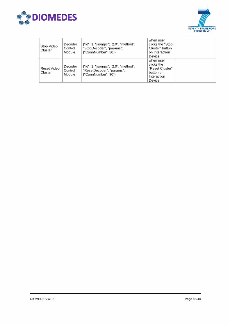
DIOMEDES WP5 Page 45/48
Stop Video Cluster
Decoder Control Module
{"id": 1, "jsonrpc": "2.0", "method": "StopDecoder", "params": {"ConnNumber": 30}}
when user clicks the "Stop Cluster" button on Interaction Device
Reset Video Cluster
Decoder Control Module
{"id": 1, "jsonrpc": "2.0", "method": "ResetDecoder", "params": {"ConnNumber": 30}}
when user clicks the "Reset Cluster" button on Interaction Device

DIOMEDES WP5 Page 46/48
APPENDIX C: CONTROL MODULE – CONFIGURATION FILE
/* Paths of Modules Executables*/
PATH_DVBTR = ..\DVB_Rx Version_0.9.1_ 2011-10-25\DVBTransceiverApp.exe
PATH_AVS_DEM_BUF = ..\AVSync_Release_0.9_27092011\AvSync_Demux_Buffer.exe
PATH_ADEM = ..\ADEM_Release8_21102011\adaptDecisionEngine.exe
PATH_P2P_CLIENT = ..\P2P\p2p.bat
PATH_AUTH_DEC = ..\SecurityClient-adm-0.9.5\security_client.bat
/*end*/
/* IP Adresses of Modules */
IP_DVBTR = 127.0.0.1
IP_ADEM = 127.0.0.1
IP_P2PCLIENT = 127.0.0.1
IP_BUFFERMODULE = 127.0.0.1
IP_AUTHDECMODULE = 127.0.0.1
IP_DECODERCONTROL = 127.0.0.1
IP_AUDIOCLUSTER = 127.0.0.1
IP_MAIN_SEED_SERVER = 192.168.10.66
/* end*/
/* Ports of Modules */
PORT_JSON_DVBTRMODULE = 8088
PORT_JSON_ADEM = 8000
PORT_JSON_P2PCLIENT = 2001
PORT_JSON_BUFFER = 5000
PORT_JSON_AUTHDECMODULE = 4445
PORT_JSON_DECODERCONTROL = 8002
PORT_JSON_AUDIOCLUSTER = 9020
/* end*/

DIOMEDES WP5 Page 47/48
APPENDIX D: ADAPTATION DECISION, DECODER CONTROL MO DULE AND ESDEMUX – CONFIGURATION FILE {
"IP":
{
"DECODER_CTR" : "127.0.0.1",
"ADAPT_ENGINE" : "127.0.0.1",
"ESDEMUX" : "127.0.0.1",
"DECODER" : ["127.0.0.1", "127.0.0.1", "127.0.0.1",
"127.0.0.1", "127.0.0.1", "127.0.0.1" ],
"RENDERER" : ["127.0.0.1"],
"CONTROL_MOD" : "127.0.0.1"
},
"JSON_PORT":
{
"ADAPT_ENGINE" : 8000,
"ESDEMUX" : 8001,
"DECODER_CTR" : 8002,
"CONTROL_MOD" : 8080,
"RENDERER" : 8086,
"VIDEO_DECODER" : 4010
},
"TS_INPUT_PORT":
{
"ESDEMUX" : 8009,
"VIDEO_DECODER" : 4000
},
"VIEWLIST":
{
"VIEWIDs" : [0, 1],
"PIDs" : [4115, 4113, 4114],
"LAYERs" : ["b", "b", "e" ],
"PORTs" : [4000, 4001 ]
},
"MODULE_FEATURES":
{
"DECODER_CTR" :

DIOMEDES WP5 Page 48/48
{
"JSON_TO_VDECODER" : 0,
"JSON_TO_RENDERER" : 0,
"STATIC_PID" : 0
},
"ESDEMUX":
{
"JSON_TO_VDECODER" : 0,
"JSON_TO_RENDERER" : 0,
"STATIC_PID" : 1
},
"RENDERER":
{
"Render mode": "stereo",
"view output": "real",
"output format": "side-by-side",
"holovisio model": 0
}
}
}


![CONFIDENTIAL Lotte Entertainment Korea Distribution Partnership [Date]](https://img.pdfslide.us/doc/110x75/56649f335503460f94c4f7b7/confidential-lotte-entertainment-korea-distribution-partnership-date.jpg)
