Embed Size (px)
Citation preview

Make the most of your energySM
Distribution Automation:Intelligent Switching and Reclosing Solutions

Due to the importance of electricity in the everyday life of people…electricity providers are under pressure to improve the reliability of supply to their customers. Providers have a number of options available to improve supply reliability.
2

3
Table of contents
Introduction ............................................................................... 4
Feeder segmentation ............................................................. 6
Remotely controllable switches .......................................... 8
Sectionalizing switchgear ................................................... 10
Recloser systems ................................................................... 12
Feeder Automation ............................................................... 16
Example cost analysis .......................................................... 20
Conclusion................................................................................22
Glossary ....................................................................................23

4
Additional primary substationsTo a large degree, the likelihood of a fault is proportional to the length of a distribution circuit — the longer the circuit, the greater the probability of a fault.
While, it is possible to reduce the number of customers that are affected by a fault by installing additional substations. However, the cost of locating, installing and commissioning a new substation can be very expensive.
Additional feeder circuitsNew feeders could be established from existing primary substations. This option reduces the number of customers per circuit and, therefore, the number of customers affected by each fault. This option would be less effective than the addition of primary substations and may not be very efficient. It is again, negated by excessive cost.
Vegetation managementBoth of the prior two options focus on reducing the affects of faults, but do not do anything to reduce the likelihood of one of the major root causes of faults which is vegetation. One thing that all utilities with overhead rural feeders have to focus upon is optimizing vegetation management. This is an operational expenditure rather than a capital expenditure, but nevertheless an extremely important activity for electrical utilities. It is essential effort that contributes to reducing a specific root cause of many interruptions.
Covered conductorAnother option to reduce the number of faults would be to remove bare overhead conductors and replace them with covered conductors. This will reduce faults caused by birds, animals, tree branches or other windblown material that is contacting the line. Using a covered conductor, particularly in wooded areas, will help to reduce faults. Covered conductors are certainly not foolproof and their performance under high impulse conditions can be a problem. The biggest drawback with them is the cost. Replacing the conductors in large portions of the network is not generally an economically viable option.
Underground circuitsIn theory, an option that eliminates overhead sources of faults would be to place circuits underground. This would remove any weather or vermin-related faults and improve reliability and win favor with environmental lobby groups. The use of trenchless or narrow trench technology can significantly reduce cost. However, considering the feeding distances involved, the cost would still be astronomical.
A significant redesign of networks would also be required, as the typical overhead circuit (with very long feeding distances and many spur lines teed-off) is not really suited to an underground system. Some practical difficulties could be manifested in complications with future fault location, which could cause long interruptions to supply. Low cost, padmounted transformers and switchgear would be an essential requirement of such a system.
Feeder automation solutionsIn an effort to improve reliability of supply, providers are rethinking the levels of automation that is being deployed in their distribution feeders.
Studies of faults on overhead feeder networks have shown that 60 – 70% of the faults are transient (temporary).
Examples of transient faults include:
> conductors clashing in the wind
> tree branches falling on overhead conductors
> animals or birds
> lightning strikes
> underground conductor failures
Deploying an auto-reclosing scheme should, therefore provide a viable solution where the transient fault can be cleared without interrupting supply to the customer. In most cases, no further operator assistance or interaction would be required
However, some faults are permanent. For example, faults due to transformer failures and fallen power lines due to motor accidents or storms cannot be restored automatically. Protection design and equipment has been designed to minimize damage by interrupting supply to a segment containing a fault. The supply will remain off until the fault is removed and the protection equipment restored.
To achieve the goals of improved system reliability, electric distribution companies may have many options to evaluate, these could include:
Introduction
5
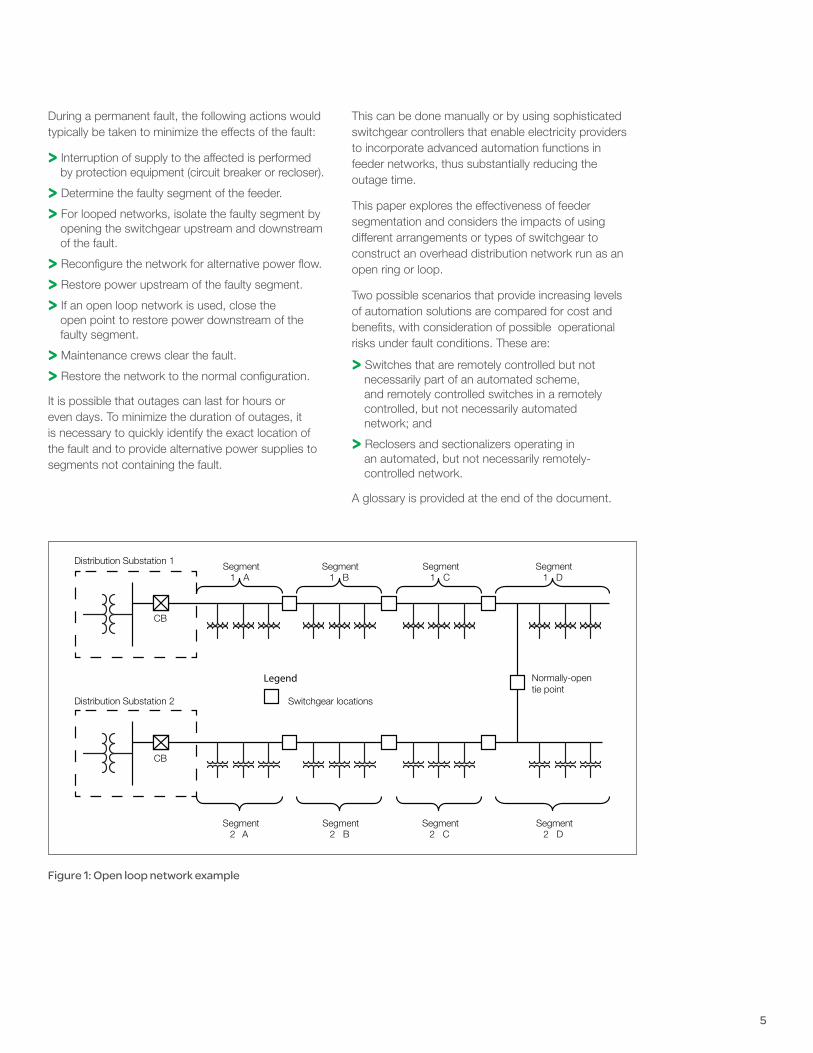
During a permanent fault, the following actions would typically be taken to minimize the effects of the fault:
> Interruption of supply to the affected is performed by protection equipment (circuit breaker or recloser).
> Determine the faulty segment of the feeder.
> For looped networks, isolate the faulty segment by opening the switchgear upstream and downstream of the fault.
> Reconfigure the network for alternative power flow.
> Restore power upstream of the faulty segment.
> If an open loop network is used, close the open point to restore power downstream of the faulty segment.
> Maintenance crews clear the fault.
> Restore the network to the normal configuration.
It is possible that outages can last for hours or even days. To minimize the duration of outages, it is necessary to quickly identify the exact location of the fault and to provide alternative power supplies to segments not containing the fault.
This can be done manually or by using sophisticated switchgear controllers that enable electricity providers to incorporate advanced automation functions in feeder networks, thus substantially reducing the outage time.
This paper explores the effectiveness of feeder segmentation and considers the impacts of using different arrangements or types of switchgear to construct an overhead distribution network run as an open ring or loop.
Two possible scenarios that provide increasing levels of automation solutions are compared for cost and benefits, with consideration of possible operational risks under fault conditions. These are:
> Switches that are remotely controlled but not necessarily part of an automated scheme, and remotely controlled switches in a remotely controlled, but not necessarily automated network; and
> Reclosers and sectionalizers operating in an automated, but not necessarily remotely-controlled network.
A glossary is provided at the end of the document.
Figure 1: Open loop network example
CB
CB
Segment 1 A
Segment 1 B
Segment 1 C
Segment 1 D
Segment 2 A
Segment 2 B
Segment 2 C
Segment 2 D
Legend Normally-opentie point
Switchgear locations
Distribution Substation 1
Distribution Substation 2

6
Feeder segmentationAs discussed in the introduction of this paper, distribution utilities have a number of options available to improve the reliability of supply.
These are:
> additional primary substations
> additional feeder circuits
> vegetation management
> covered conductor
> underground circuits
> feeder automation
Reliability gains can also made by increasing the protection capabilities. This is not limited to the latest protection algorithms. It also includes breaking the feeder into smaller segments. This reduces the number of customers per segment and, therefore, the number of customers that would be affected by a fault. The following paragraph explores the effect that segment lengths have on reliability.
Increased number of segments per feederFor this example, consider a theoretical radial feeder. It is assumed that the probability of a fault is the same along the entire length of the feeder. By dividing the feeder into multiple segments the probability that a fault would occur in a specific segment is:
PZ = PF x (LZ/L) where:
L = the length of the feeder;
LZ = the length of the segment; and
PF = the probability that a fault would occur anywhere on the feeder.
It is possible to calculate the impact when the feeder is divided into multiple segments of equal length.
Number of Segments
Segment fault probability
Improvement
1 P1 = PF
2 P2 = PF x 1/2 P2/P1 = 50%
3 P3 = PF x 1/3 P3/P2 = 66%
4 P4 = PF x 1/4 P4/P3 = 75%
Table 1: Reliability improvement
Unfortunately, these improvement figures do not tell the full story. To get the full picture it is necessary to revisit the basic radial feeder, look at the probability of an outage in each segment and then expand the theory to a looped network.

7
Radial feeder
Seg A B C D
F MP1 MP2
Where “F” represents the switchgear closest to the substation and “MP” represent switchgear anywhere along the feeder.
Probability of a fault in each segment is:
PA PB PC PD
Probability of an outage in each segment is:
PS PS+A PS+A+B PS+A+B+C PS+A+B+C+D
Where PS is the probability of losing supply at the primary substation. PS should be negligible and this simplifies the probability of an outage in each segment. (Notation: PA+B+C+D = PA + PB +PC + PD)
PA PA+B PA+B+C PA+B+C+D
For equal segment lengths and by using PZ = PF x (LZ/L) and the above it is possible to show what percentage of permanent faults will affect each segment. For feeders with four segments:
4 25% 50% 75% 100%
For feeders with three segments:
3 33% 66% 100%
For feeders with two segments:
2 50% 100%
Notice how the probability of an outage increases further away from the substation. From this example, it is clear that not all customers benefit equally from additional segments on the feeder. Only customers connected to the first segment will experience the improvements calculated in Table 1.
Table 2: Radial feeder
The example above clearly shows how the outages in each segment are affected by the number of faults in that specific segment and the faults occurring in upstream segments.
Looped networks are used to reduce the number of outages for segments located further away from the substation and to overcome this stepped increase in outages.
Open loop networkIn a looped network, the switchgear immediately upstream and downstream of a fault are opened to isolate the fault, and the normally-open point is closed to restore power downstream of the faulty
segment. Only the segment containing the fault experiences an outage until the fault is removed and the network is restored to the original configuration.
The outage probability of each segment is not affected by the probability in adjacent segments.
How would a looped network affect these figures?
F MP1 MP2 NO
Seg A B C D
Probability of an outage in a looped network is:
PA PB PC PD
For feeders with multiple segments of equal length the probability of an outage in each segment is 1/4, 1/3 or 1/2 respectively for four, three or two segments.
By comparing these probability figures to those determined for a radial feeder, it is possible to calculate the improvements achieved with a loop network.
4 25% 25% 25% 25%
Improvement 25% 50% 75%
3 33% 33% 33%
Improvement 33% 66%
2 50% 50%
Improvement 50%
Table 3: Open loop network
By reducing the length and increasing the number of segments in a feeder it is possible to improve the reliability of supply. However, not all customers benefit equally from this investment and looped networks are often used to improve supply reliability throughout the feeder.
Feeder segmentation is achieved by using different technologies ranging from sophisticated reclosers and sectionalizers through SCADA-controllable load-break switches to manually operated air- break switches.
The technology used in feeders differs from utility-to-utility and is also affected by the population density (number of customers per segment). In reality underground circuits may be used in the inner city, reclosers in substations and outer city feeders and sectionalizers in rural feeders.
The subsequent sections discuss in detail the benefit and operation of each technology based on a common feeder topology.

8
Remotely-controllable switchesIn this example, remotely-controlled load-break switches are used in an overhead feeder. Remotely-monitored Fault Current Indicators (FCIs) are used with the load-break switches, sometimes they are used separately, while sometimes they are built into the switch. These configurations add greater levels of intelligence to the loop automation scheme. The switches are used for general switching operations and, in the event of a permanent fault, an operator would use the FCI indication to determine which switches to open. This isolates the faulted segment of the feeder.
To operate such a network, a communications system is necessary, and the operation of the switches is typically performed from the control room. During a fault condition, the feeder reconfiguration is typically not done automatically.
Substation circuit breaker Closed remotely controllable switch Open remotely controllable switch
NO
Figure 2: Typical switch network
Basic operation during fault conditionsWhen a permanent fault occurs, the following steps are taken:
> The substation circuit breaker or recloser trips automatically to interrupt supply to the affected feeder.
> An operator in the control room: » identifies the faulty segment of the feeder by using the FCI indication displayed in the control room
» opens the nearest upstream and downstream switches to isolate the faulty segment using the communications network
» reconfigures the protection in substation breakers
» closes the substation circuit breaker to restore power upstream of the faulty segment
» closes the normally-open tie point to provide power downstream of the faulty segment.
Through this operation, power is restored to the healthy parts of the network. The operator would then dispatch the maintenance crews to the faulty segment of the feeder to remove the fault. Once the
entire feeder is healthy, the operator would open the normally-open point and close the remotely controllable switches to restore the network to the normal pre-faulted configuration.
Figure 3: Remotely-controllable load-break switch RL-Series
Operational risksControl room
The reaction time of the control room has a significant impact on the feeder restoration times. In practice the reaction time is influenced by:
> the availability of an operator 24 hours per day, 7 days a week
> sufficient staff of operators to monitor and react during periods of extreme fault activity – such as large storms
> reliability of communications network to monitor FCI indication and to control the switchgear
> feeder complexity
> level of automation in control room and network.
If managed correctly, control room operations would not degrade the operational efficiency of this type of network.
Faulted Circuit Indicator (FCI)
FCIs are the “eyes” of the operator. When the operator does not have a clear understanding of the fault location, the operational efficiency of the network would be reduced.
FCI functionality can be incorporated in the switchgear. These utilize switchgear-mounted Current Transformers (CTs) and sensing electronics to detect fault conditions.
FCIs can also be separate from the switchgear; these typically measure the magnetic field around the line and are simply clipped onto the conductor making it extremely easy to install. The major advantage of clip-on FCIs is that they can be installed anywhere along the feeder, and at different intervals. Because

9
of this simplicity, it is possible to relocate them as requirements change.
Two risks are associated with FCIs – false indication and no indication at all.
False indication is the situation where the FCI indicates a fault without a fault being present. This can be caused by inrush currents during switching operations and reclosing cycles. In general, no indication can also occur when low level phase and ground fault conditions are not detected by the FCIs, this would result in the absence of FCI indication. It is possible to overcome these risks by matching the detection capabilities of the FCI to that of the primary protection devices in the feeder.
It is also possible that the absence of indication is caused by communication failure.
In either case, an operator may be left with a dead feeder and inaccurate FCI indication on their SCADA, OMS or DMS mimic panel. This can mislead the operator about the actual location of the faulty segment, resulting in incorrect switching operations which would increase the time taken to restore power.
Communications
The integrity of the remotely controllable switch network relies significantly on the availability of communications. This key part of the system affects all aspects of network operation.
During a fault condition the protection equipment will trip. Without communications, the operator will not be able to reconfigure and restore supply. Maintenance crews will have to locate the fault and manually reconfigure the network by driving to
each unit before power is restored. This can take many hours and can cause unacceptable delays in restoring power to the customers.
Evolving solutionsWhere a communications network may be expensive or difficult to implement, and in more critical parts of networks, there is a movement away from remotely controllable switches toward “infilling” with reclosers and using the remotely controllable switches as sectionalizers. This introduces protection and automation potential to the feeder.
An example of a more sophisticated feeder is where load break switch sectionalizers are used instead of remotely controllable switches. Communications is not essential to the operation of feeders where reclosers and sectionalizers are used. These networks can be automated to improve response times and do not have to be remotely-controlled.
Figure 4: Easergy™ Flite FCI
Advantages/Disadvantages of Remotely Controllable Switches
Advantages Disadvantages
> Relatively low initial cost of switchgear.
> Much lower outage times when compared with manually-operated switches (no communications).
> Existing Communications Networks, like AMI, can be leveraged to communicate with remotely controllable switches.
> Operator can intervene and choose different modes of operations depending on the situation.
> Saves field crew time and truck rolls for both normal/emergency switching operations.
> Operation is dependent on the integrity and availability of the communications network.
10
Sectionalizing switchgearTo analyze the use of sectionalizer logic in a feeder, consider the same open loop topology from the previous example, but replace the remotely controllable switches with sectionalizing switches.
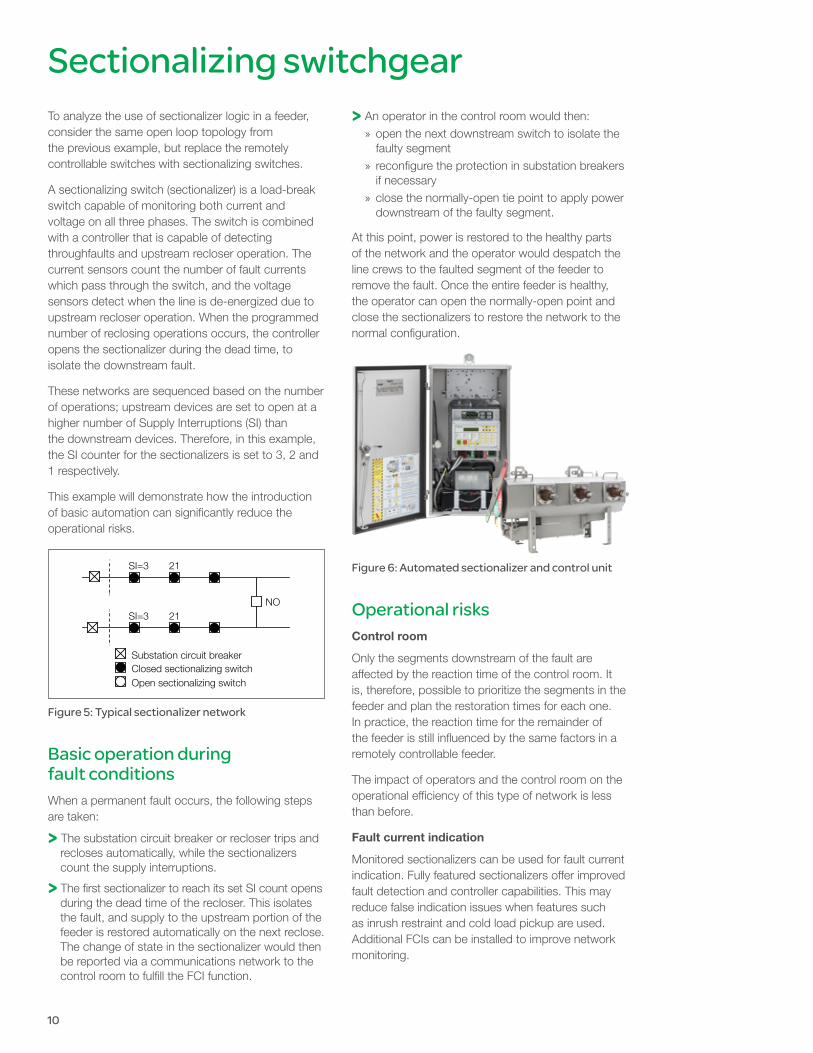
A sectionalizing switch (sectionalizer) is a load-break switch capable of monitoring both current and voltage on all three phases. The switch is combined with a controller that is capable of detecting throughfaults and upstream recloser operation. The current sensors count the number of fault currents which pass through the switch, and the voltage sensors detect when the line is de-energized due to upstream recloser operation. When the programmed number of reclosing operations occurs, the controller opens the sectionalizer during the dead time, to isolate the downstream fault.
These networks are sequenced based on the number of operations; upstream devices are set to open at a higher number of Supply Interruptions (SI) than the downstream devices. Therefore, in this example, the SI counter for the sectionalizers is set to 3, 2 and 1 respectively.
This example will demonstrate how the introduction of basic automation can significantly reduce the operational risks.
Substation circuit breakerClosed sectionalizing switchOpen sectionalizing switch
NO
SI=3 21
SI=3 21
Figure 5: Typical sectionalizer network
Basic operation during fault conditionsWhen a permanent fault occurs, the following steps are taken:
> The substation circuit breaker or recloser trips and recloses automatically, while the sectionalizers count the supply interruptions.
> The first sectionalizer to reach its set SI count opens during the dead time of the recloser. This isolates the fault, and supply to the upstream portion of the feeder is restored automatically on the next reclose. The change of state in the sectionalizer would then be reported via a communications network to the control room to fulfill the FCI function.
> An operator in the control room would then: » open the next downstream switch to isolate the faulty segment
» reconfigure the protection in substation breakers if necessary
» close the normally-open tie point to apply power downstream of the faulty segment.
At this point, power is restored to the healthy parts of the network and the operator would despatch the line crews to the faulted segment of the feeder to remove the fault. Once the entire feeder is healthy, the operator can open the normally-open point and close the sectionalizers to restore the network to the normal configuration.
Figure 6: Automated sectionalizer and control unit
Operational risksControl room
Only the segments downstream of the fault are affected by the reaction time of the control room. It is, therefore, possible to prioritize the segments in the feeder and plan the restoration times for each one. In practice, the reaction time for the remainder of the feeder is still influenced by the same factors in a remotely controllable feeder.
The impact of operators and the control room on the operational efficiency of this type of network is less than before.
Fault current indication
Monitored sectionalizers can be used for fault current indication. Fully featured sectionalizers offer improved fault detection and controller capabilities. This may reduce false indication issues when features such as inrush restraint and cold load pickup are used. Additional FCIs can be installed to improve network monitoring.
11
Similar to the remotely controllable switch network, communication failure can result in incorrect switching operations and an increase in the time taken to restore power.
Communications
Due to the sectionalizer logic, the feeder upstream from the fault is unaffected by communication problems. However, communications are required to sectionalize the downstream portion of the network and to control the normally-open point.
If a complete breakdown of communications is experienced, it is possible for the control room to use customer calls to determine the affected parts of the feeder. In this way, the maintenance crews can focus their effort on the first sectionalizer within
the “complaints area”, open it and then close the normally-open point.
Although not an ideal solution, in this case the feedback and information from customers can be very helpful.
Evolving solutionsThe operational risks were substantially reduced with the introduction of sectionalizers in the feeder. However, due to the limited protection features and the faults affecting the entire feeder, this solution may not be suitable for high priority customers – especially industrial customers.
Automatic circuit reclosers are designed to overcome these problems.
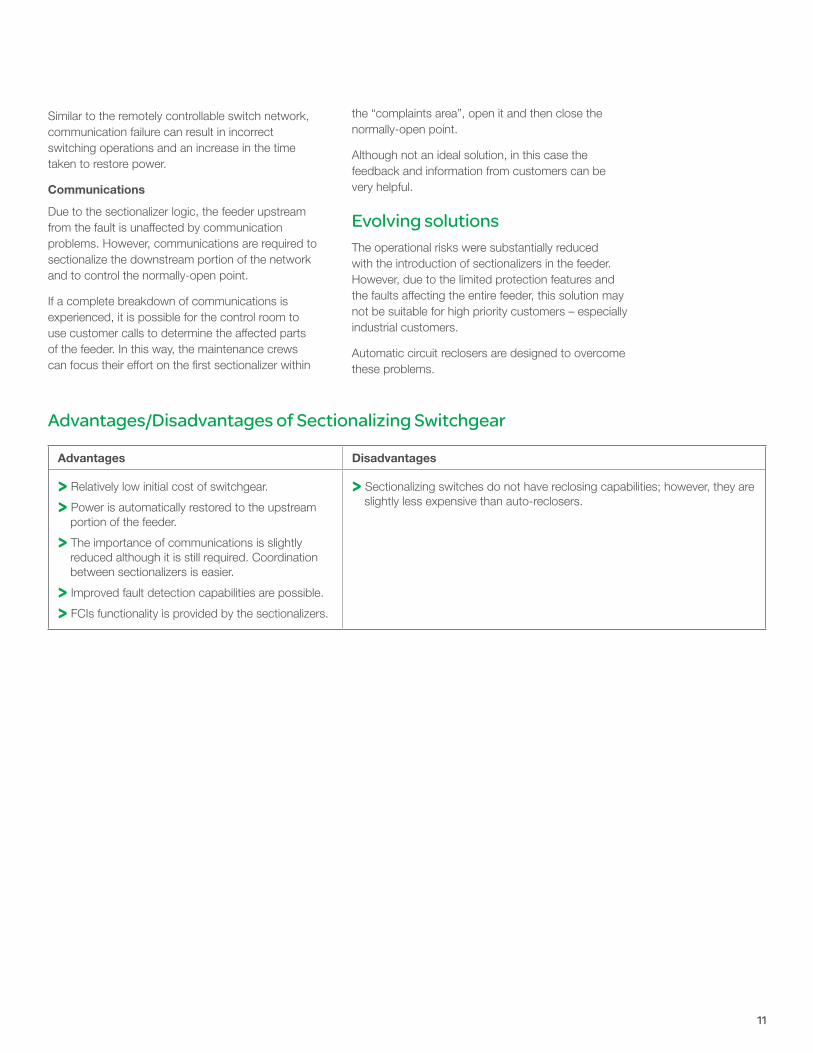
Advantages/Disadvantages of Sectionalizing Switchgear
Advantages Disadvantages
> Relatively low initial cost of switchgear.
> Power is automatically restored to the upstream portion of the feeder.
> The importance of communications is slightly reduced although it is still required. Coordination between sectionalizers is easier.
> Improved fault detection capabilities are possible.
> FCIs functionality is provided by the sectionalizers.
> Sectionalizing switches do not have reclosing capabilities; however, they are slightly less expensive than auto-reclosers.

12
Reclosing systemsToday’s reclosers are capable of advanced protection, communication, automation and have additional analytical functionality. With an abundance of processing power at their disposal, utilities now have the flexibility to use the recloser as a stand-alone unit in a remote location, or to integrate several units into an automation system.
Whatever the application, the reclosers are flexible enough to evolve with the utility’s requirements.
Reclosers monitor current, voltage, frequency and the power flow direction to protect the feeder. By coordinating the reclosers correctly, only the recloser that is the closest to the fault will trip. This is very important for the successful implementation of reclosers. A recloser can be programmed to automatically reclose when it tripped due to a fault.
Using this logic, power is restored automatically in the event of a transient fault. However, if the fault is permanent the recloser will trip again and remain open (lockout). It is possible to have up to a maximum of four trips to lockout.
Coordination of reclosersTo achieve the required coordination on series reclosers, the operating time of each recloser must be faster than any upstream device and slower than any downstream device. That is, for the typical recloser network shown in Figure 8, where a specific fault current is flowing through the network, “MP2” will trip quicker than “MP1” and “MP1” will trip quicker than “F”. The instant the recloser closest to the fault trips, current through the other upstream reclosers reduce to load current and the sequence resets.
This ensures that only the recloser immediately upstream of the fault will trip. A safe margin (approximately 200 ms) between operating times of successive devices must be maintained for all fault levels on the network being protected.
Pre-programmed Inverse Definite Minimum Time (IDMT) protection curves or definite time to trip are used for phase and ground over-current protection. These protection curves allow close orchestration with substation protection relays and other protection devices.
13:52:3313:52:34
13:52:3513:52:36
13:52:3713:52:38
13:52:3913:52:40
0
200
400
600
800
1000
1200
1400
Curr
ent (
A )
Time (hh:mm:ss)
Ground Current A phase B phase C Phase
Fast Trip
Short 1streclose time
Ground fault propagates into apermanent three phase fault
Delayed Trip
Long 2nd reclose time
Fast Trip to Lockout
Load current
InitialGround fault
Figure 7: Typical timing diagram of a reclose sequence

13
Feeders with different electrical characteristics require different protection strategies. Distribution utilities worldwide have developed their own strategies to suit their particular system conditions. For example, fault analysis may show that the primary causes of transient faults on a network are:
> lightning induced power surges
> wildlife getting caught in the power lines
> trees or branches falling on the lines.
Independent configuration of the time to trip for each protection operation in the reclose sequence allows the utilities to optimize the protection strategy for each network.
A protection strategy could typically be:
A. The fault is first assumed to be lightning related. A fast IDMT curve with a small time multiplier (e.g., 0.05x) and an instantaneous element is used to ensure short exposure to the initial fault current.
B. This operation is followed by a very short reclose time (e.g., 0.5 sec) to limit the effects on electronic equipment.
C. If the fault is not cleared, on the subsequent auto-reclose, a slow IDMT curve with a long operating time allows tree or animal induced faults on rural spur lines to be cleared by upstream fuses.
D. The reclose time that follows is long (e.g., 5 sec) to allow the animal or branch to fall clear of the line if it is on the feeder or it did not cause fuse operation.
E. If the fault is still present after the auto-reclose, it is assumed to be permanent, and a fast IDMT curve minimizes exposure to fault currents.
Basic operation during fault conditionsIt is possible to operate this type of network in either a “manual” mode where the operator has to perform the reconfiguration of the network, or in a “Loop Automation” mode where the reclosers perform all the task automatically.
Substation circuit breakerClosed automatic circuit recloserOpen automatic circuit recloser
NO
F MP1
F MP1
MP2
TIE
MP2
Figure 8: Typical recloser network
Manual mode
In the “manual mode” the following actions are taken:
> The recloser immediately upstream of the fault automatically trips, recloses to lockout and remains open.
> An operator: » determines the location of the fault from the recloser status and/or additional FCIs;
» opens the next downstream recloser to isolate the faulty segment;
» reconfigures the protection settings in anticipation of reverse power flow, and
» Closes the normally-open point to restore power downstream of the faulty segment.
With power restored to the healthy parts of the network and the operator can dispatch the line crews to the faulted segment of the feeder. Once the entire feeder is healthy, the operator can open the normally-open point, reconfigure, and close the reclosers to restore the network to the normal pre-faulted configuration.
Figure 9: Reclosers

14
Intelligent Loop Automation
It is important to note that protection is the first and foremost function of the reclosers, even in a loop automation scheme. A more sophisticated recloser is required to perform both protection and automation functions. In addition to these, the reclosers have to measure power flow and voltage on both sides of the recloser.
To explain the basic operation of a loop automation scheme, let’s first define the reclosers as follows:
> Feeder recloser (F) – Recloser closest to the substation.
> Tie (TIE) – The open point recloser where the two feeders meet. This is a normally-open point (NO).
> Mid-point reclosers (MP) – All the reclosers positioned between the feeder and tie reclosers.
Each of these reclosers is programmed with a different set of rules when controlled by loop automation, which can be simplified as follows:
> The feeder recloser trips when it loses supply.
> The mid-point recloser changes to the reverse power flow protection settings when it loses supply.
> The tie recloser closes when it detects that supply to one side of the network has been lost.
Loop automation uses time, voltage, power flow and these simple rules to isolate the fault and reconfigure the network without the need for any communications or operator assistance.
In a loop automation network the following actions will take place when a fault occurs:
> The recloser immediately upstream of the fault automatically trips, recloses to lockout and remains open.
> Reclosers downstream of the fault automatically change the protection settings in anticipation of power flowing in the opposite direction.
> The normally-open tie recloser closes automatically.
> Since the fault still being present, the recloser immediately downstream of the fault trips and locks out without reclosing.
This will automatically restore power to the healthy parts of the network. An operator can now dispatch line crews to the faulted segment. It is also possible for the loop automation system to restore the original configuration when the fault is cleared.
Operational risksControl room
In a manual system, the segment downstream of the fault is affected by the reaction time of the control room. To assist the operator during feeder reconfiguration, recloser systems are capable of automatically applying forward or reverse protection settings when power flow changes. In such a system, the operator is not required to change the settings in all the reclosers.
A loop automation system does not require any operator intervention – all the operator has to do is dispatch the line crews.
Fault current indication
The ON/OFF status and even logs of reclosers are commonly used to determine the location of faults on feeders. With this inherent FCI functionality of the recloser, false indication is eliminated.
Separate FCIs can be used in conjunction with the reclosers to assist the operators in determining the exact location of faults on long feeders.
Communications
Communications are not required in the loop automation scheme. However, it may be desirable to do so in order to monitor the status of the network at several key points to assist maintenance crews.
In a manual recloser system, the feeder upstream from the fault is unaffected by communication problems, but communication is required to reconfigure the downstream portion of the network and to control the normally-open point.
Evolving solutionsReclosers provide a very robust operational system, capable of protecting the feeder irrespective of operational factors. The number of customers affected by permanent faults is minimized. To further improve the feeder’s immunity to operational risks may be very difficult and can be extremely expensive.
To further improve distribution network reliability, the focus shifts away from reducing operational risks to improving reliability of supply through feeder automation.
Reclosing systems (cont.)

15
Advantages Disadvantages
> Customers upstream from the fault are not affected at all.
> The Reclosing Loop Automation scheme does not require communications, but is enhanced with it.
> Power is restored quickly without any operator intervention, when the loop automation scheme is used.
> Advanced protection features are available.
> Multiple groups of settings are pre-set to ensure an effortless feeder reconfiguration when needed.
> Diagnostic tools are available to assist in feeder analysis.
> With minimal effort, the manual system can be upgraded to the loop automation system.
> Incremental cost difference with reclosing systems compared to sectionalizing only.
Advantages/Disadvantages of Recloser Systems

16
A feeder automation network combines reclosers and sectionalizers in a feeder to provide orchestration on both current/time and number of operations. This is accomplished by introducing up to two sectionalizers in each zone protected by a recloser.
Closed automatic circuit recloser Closed sectionalizer
SI=3 2 SI=3 2 MP
F SI=3
SI=2
sect 1
sect 2
sect 3
F
Figure 10: Feeder automation network
Basic operation during fault conditionsIn a feeder automation network, the reclosers protect the downstream portion of the feeder up to the next recloser. Similar to the recloser network described earlier, the recloser will trip and reclose in the presence of a fault. The sectionalizers count the through-faults similarly to the sectionalizing switchgear network described earlier. The difference is that if the fault occurs downstream of a sectionalizer, the sectionalizer closest to the fault will open before the recloser reaches lockout.
For this system to work correctly, it is essential that the recloser is configured with four trips to lockout and the sectionalizers are configured with SI (supply interrupt) counters of three and two respectively.
For a feeder using one sectionalizer instead of two, the recloser is set to three trips to lockout and the supply interrupt counter in the sectionalizer is set to two. See the sectionalizer timing diagram in Figure 12 for more information.
Figure 11: Gas or Air insulated recloser
Operating time
ON
OFF
Sectionalizer source side voltage LIVE
DEAD
Sectionalizer Current Fault
Zero
Trip
Off
Recloser Deadtime
SI = SI+1
Sectionalizer Open command
Sectionalizer contact position
Figure 12: Sectionalizer timing diagram
This diagram shows the importance of having a recloser dead time greater than the sectionalizer operating time. If this rule is ignored, the sectionalizer contacts can open when the power is ON. This will result in the switch interrupting fault current, which can drastically shorten the operational life of the switch, and the recloser will trip to lockout.
The logic of a feeder automation network is best explained using timing diagrams for different fault locations.
Switch Automation Schemes

17
Firstly, what happens when a fault occurs in Section 1?
F I=3S I=2sect1
sect2
sect3
S1 S2
F
S1
S2
On Off
On Off
On Off
Figure 13: Fault in Section 1
The recloser “F” trips to lockout, remains Open (OFF) and the sectionalizers do not change state. When a fault occurs in section 2 the recloser trips and recloses twice before the sectionalizer “S1” opens to isolate the fault. The third reclose operation restores power up to “S1”. The recloser “F” sequence resets after the sequence reset time.
F SI=3 SI=2 sect 1
sect 2
sect 3
S1 S 2
F
S1
S2
On
Off
On
Off
On
Off
SI=3
Sequence reset
Figure 14: Fault in Section 2
A fault in section 3 will cause the recloser to trip and reclose once before the sectionalizer “S2” opens to isolate the fault. Both sectionalizer count the interruptions. The second reclose restores power upstream of “S2”. The sequence resets in the recloser “F” and “S1” after the sequence reset time.
F SI=3 SI=2 sect 1
sect 2
sect 3
S1 S 2
F
S1
S2
On
Off
On Off
On
Off
SI=1 S I=2
Sequence reset
Figure 15: Fault in Section 3
Advantages of Feeder AutomationAdvantages
> Improved supply reliability when the segments are broken into smaller sections, therefore reducing the length of feeder that can be isolated in the event of a fault.
> Protection coordination is relative easy.
> Flexible solutions are possible.
> Existing recloser or sectionalizer networks can be upgraded to incorporate full feeder automation with relative ease.
> The advantages of sectionalizing switch and recloser networks are combined in feeder automation networks.
> Creative protection solutions are possible at relatively low cost.
> With full directional capabilities, the network will automatically reconfigure itself when the normally-open point is closed in the event of a fault.

18
Feeder automation in a looped networkWhen feeder automation is used in a looped network, it is necessary to consider using reclosers and sectionalizers with advanced capabilities such as directional protection and intelligent loop automation schemes.
With full directional capabilities, the reclosers and sectionalizers are configured for protection with power flowing in both the forward and reverse directions. Protection in both directions is active at any given point in time. This allows the utility to manually close the normally-open point in the event of a fault, without having to reconfigure the other switchgear in the feeder. It is possible to focus on the communications link to the normally-open point and, by ensuring that it is reliable, power restoration will be possible.
In a network using loop automation, the switchgear controllers will automatically reconfigure the protection settings following a permanent fault conditions. Operation is very similar to that of a recloser-only loop automation scheme. The major difference is that reclosing is allowed to enable sectionalizing, but the SI settings are reduced.
F S1 S2 MP1sect 1
sect 2
sect 3
Normal power flow direction
Figure 16: Feeder Automation Loop
In the segment shown above, recloser “F” protects the segment during the normal configuration while recloser MP1 is protecting the segment when power is restored. In a forward direction the following settings are used:
> “F” – forward protection and four trips to lockout.
> “S1” – forward detection and SI = 3.
> “S2” – forward detection and SI = 2.
> “MP1” – forward protection and four trips to lockout.
In the reverse direction the settings will change to:
> “F” is the closest recloser to the substation. A fault upstream of “F” will cause a loss of supply at the recloser and it will open to isolate the substation. It does not change protection settings.
> “S1” – reverse detection and SI = 1.
> “S2” – reverse detection and SI = 2.
> “MP1” – reverse protection and three trips to lockout.
With only one sectionalizer per segment the settings are slightly different.
F S1 MP1
Normal power flow direction
sect1
sect2
Figure 17: Feeder Automation with one sectionalizer
In a forward direction the following settings are used:
> “F” – forward protection and three trips to lockout.
> “S1” – forward detection and SI = 2.
> “MP1” – forward protection and three trips to lockout.
In the reverse direction the settings will change to:
> “F” is the closest recloser to the substation. A fault upstream of “F” will cause a loss of supply at the recloser and it will open to isolate the substation. It does not change protection settings.
> “S1” – reverse detection and SI = 1.
> “MP1” – reverse protection and two trips to lockout.
A feeder automation network provides a flexible solution to any protection challenge and is capable of evolving with the distribution requirements.
Switch Automation Schemes (cont.)

Automation of Feeder Switching and Reclosing improve reliability, minimize customer service interruptions, and save utility operators time and money. The field and control center have increased awareness of the state of the network and fault locations are able to respond to emergency outages.
19

20
Feeder Automation Sectionalizers
Switchgear l ocations
33/11kV Substation
6.2mi
7.8mi
6.2mi
6.2mi
6.2mi
6.2mi
6.2mi
6.2mi6.2mi
6.2mi
6.2mi
6.2mi
3.1mi
3.1mi
3.1mi
3.1mi
3.1mi
3.1mi
3.1mi
3.1mi
6.2mi
4.7mi
4.7mi
7.8mi
Feeder 1
Feeder 2
Figure 18: Example network used in cost analysis
Network descriptionThe basic network shown in Figure 18 will be used to analyze the cost implications of applying different levels of capabilities in a network. The network contains two radial feeders, tied together using a normally-open point. Each feeder comprises of three segments and each segment contains two spur lines. The main-line of feeder 1 is 23.3mi (37.5km) long and the total length of the spur lines is 38.8mi (62.5km). Feeder 2’s main-line is 24.9mi (40km) long and the combined length of the spur lines is 37.3mi (60km). The overall length of each feeder is 62.1mi (100km) and the network supplies power to and area of approximately 621.4mi² (1000km²).
Reclosers are used as substation breakers. Switchgear locations are indicated along the mainline and the length of each section is shown. The location of the sectionalizers used in analyzing the feeder automation circuit is also shown on the diagram. These sectionalizers are ignored in the analysis of other network configurations.
The load per feeder is typically 4MW with 2MW, 1.5MW and 0.5MW of load in segment A, B and C respectively. (A is the closest to the substation.)
Costs consideredThe cost of the distribution infrastructure is assumed equal for all of the network configurations and is not included in this analysis. Communication and other equipment associated with the control room are also not part of the analysis.
Table 4 provides a breakdown of the costs considered in the analysis. For comparison purposes, the cost of each item is expressed as a multiple of the remotely controllable switch’s cost. These relationships may vary slightly from utility to utility.
The analysis firstly considers average revenue lost due to outages. This average is based on the level of functionality, topology and segment lengths used in the network. The same average response and fault repair times were assumed for each network type. Although networks often evolve substantially during the useful service life of 30 years, this analysis assumed the same load distribution throughout the period.
A remotely controllable switch network relies heavily on the integrity of the communications infrastructure
Example cost analysis

21
to work reliably. Therefore, the analysis includes a fiber optic communications line installed along the entire length of the main-line. Separate FCIs are also included for each switch.
A radio control network is assumed for both the sectionalizing and manually controlled recloser networks. Although communications are not required in the automated recloser and feeder automation networks, some basic communications were included to alert the control room of automation actions.
Description Cost Multiple
Remotely Controllable
Sectionalizer Recloser Manual
Recloser Automated
Feeder Automation
Cost due to outages (30 years) Qty Value Qty Value Qty Value Qty Value Qty Value
Remotely Controllable 9.08 p/a 30 272 — — — — — — — —
Sectionalizer 8.76 p/a — — 30 263 — — — — — —
Recloser manual 8.45 p/a — — — — 30 254 — — — —
Recloser automated 7.65 p/a — — — — — — 30 230 — —
Swiching Automation Schemes 4.58 p/a — — — — — — — — 30 137
Costs of Protection Equipment and Communications Infrastructure
Substation recloser 5 2 10 2 10 2 10 2 10 2 10
Remotely Controllable switch 1 5 5 — — — — — — — —
FCIs 0.5 5 2.5 — — — — — — — —
Sectionalizers 3 — — 5 15 — — — — — —
Advanced sectionalizers 4 — — — — — — — — 6 24
Reclosers 5 — — — — 5 25 — — — —
Advanced reclosers 6 — — — — — — 5 30 5 30
Installed optical fiber comms (per km) 0.3 77.5 23.25
Phone/Radio comms (per point) 0.2 — — 5 1 5 1 5 1 5 1
Cost due to outages — — 272 — 263 — 254 — 230 — 137
Cost of protection equipment — — 41 — 26 — 36 — 41 — 65
Total Costs of Equipment and Outages
— — 313 — 289 — 290 — 271 — 202
Cost differential [%] — — — — -8 — -8 — -14 — -35
Table 4: Cost analysis breakdown
Due to the inherent FCI functionality of recloser and sectionalizers, separate FCIs are not included in the analysis where these devices are used.
The analysis also refers to two types of reclosers and sectionalizers – advanced and normal. Additional features such as full directional protection capabilities, additional automation features (such as loop automation), and powerful analytical tools are available in the advanced products.

22
This paper describes a range of feeder protection and segmentation options available in today’s technology-driven market. Although the options were explained using switchgear located on the main-line of the network, it is possible to apply the techniques to branch lines too. Existing networks can also keep up with future requirements by evolving to more sophisticated technology. In some cases it may be as easy as a firmware/software upgrade.
Select your supplier carefully. Ensure that the hardware platform is powerful and flexible enough to ensure accurate and reliable operation where and when you need it.
Conclusion
ResultsThe analysis considers the initial capital investment and the impact of supply reliability to determine the optimum long-term investment. Table 4 shows the impact of each component in the analysis and helps to derive an order of preferred solutions to a distribution system:
1. Feeder automation network
2. Automated recloser network
3. Manual recloser network
4. Sectionalizer network
5. Remotely Controllable switch network with intelligent loop automation
The lack of solutions in the remote controllably switch network contributes to the high level of revenue lost due to outages. The cost of the communications network increases the cost of the initial investment substantially. These “hidden” costs are sometimes overlooked and can drastically reduce the return on investment.
Although the feeder automation network requires the largest initial capital investment of all, the benefit of such a network is easily realized when the reduction in revenue loss due to outages are considered.

GlossaryTerm Description
Cold Load Pickup When a feeder has been without power for an extended period of time the load will lose its diversity. All the thermostats will be turned on. Air conditioners, fridges, freezers, hot water systems, etc. will all turn on when the feeder is energized. This will cause an overload which can last for several minutes. Cold load pickup overcomes this effect.
Dead time This is the duration where the recloser is OFF, after a protection trip and before it recloses.
Inrush restraint The short term over-current flowing through a feeder, the instant it is energized, is known as inrush current. Inrush restraint takes into consideration the short burst of these currents.
Lockout Lockout is the state where the recloser remains open and no further close operation is possible until the operator resets the recloser.
Operating time This is the time it takes for a sectionalizer to OPEN after a trip command was issued.
Supply Interrupt (SI) counter A sectionalizer increments the supply interrupt counter when, after it detected a downstream fault, the current and voltage drop to zero.
SAIDI System Average Interruption Duration Index is a KPI utilized by utilities and regulators.
CAIDI Customer Average Interruption Duration Index is a KPI utilized by utilities and regulators.
SAIFI System Average Interruption Frequency Index is a KPI utilized by utilities and regulators.
FCI Faulted Circuit Indicators installed on power lines tell crews and operators which direction to look for faulted segments.
Control Center Central location where system operators utilize SCADA software and other systems to monitor the transmission and distribution grid.
SCADA Supervisory Control and Data Acquisition. These software and hardware systems provide real time measurements and control capabilities for the control center and system operators.
Communications Peer-to-Peer or mesh networking providing the ability of devices to communicate with one another as well as with the control center.
FLISR Fault Location Isolation and Supply Restoration. This is an example of an Automated Switching Scheme designed to isolated faulted segments and restore power to unfaulted segments automatically. This may also be referred to as Loop Automation or Smart Sectionalizing.
23

Schneider Electric USA
1415 S. Roselle RoadPalatine, IL 60067 Tel: 847-397-2600Fax: 847-925-7500www.schneider-electric.us/go/utility
Document Number 0107BR1402
©20
14 S
chne
ider
Ele
ctric
. All
Rig
hts
Res
erve
d. S
chne
ider
Ele
ctric
, EA
SE
RG
Y a
nd M
ake
the
mos
t of y
our
ener
gy a
re t
rad
emar
ks o
wne
d by
Sch
neid
er E
lect
ric In
dus
trie
s S
AS
or
its a
ffili
ated
com
pan
ies.
All
othe
r tr
adem
arks
are
pro
per
ty o
f the
ir re
spec
tive
owne
rs.
September 2014
For more information… Scan the QR code to email one of our subject matter experts about our distribution feeder automation solutions or visit us at www.schneider-electric.us/go/utility.