Embed Size (px)
Citation preview

Master of Science ThesisStockholm, Sweden 2006
COS/CCS 2006-15
A B H I N A S H M U R U K E S V A N
Distributed Overlaysin Wireless Sensor Networks
K T H I n f o r m a t i o n a n d
C o m m u n i c a t i o n T e c h n o l o g y

Distributed Overlays
in Wireless Sensor Networks
Abhinash Murukesvan
Master of Science Thesis
Communication Security Lab
Ericsson Research, Ericsson AB
and
Department of Communication Systems Royal Institute of Technology (KTH)
August 2006
___________________________________________________________________________
Examiner: Prof. Gerald Maguire Jr
Supervisor at Ericsson: Supervisor: Mattias Johansson, M.Sc. Prof. Gerald Maguire Jr, IP Networks Ericsson AB Kista, Sweden
i
Abstract This thesis investigates two architectures and compares their suitability for selective application and user differentiation in sensor networks. A hierarchical architecture consisting of more capable cluster heads surrounded by weaker nodes is compared to a flat architecture of equally powerful nodes. In both architectures there exists a logical overlay network that connects the nodes, depending on the application and user.
Furthermore, a broadcast encryption scheme is proposed to aid in distributing keys to nodes for secure communication and to maintain these restricted groups.
Sammanfattning Den här examensarbete undersöker två arkitekturer och jämför dess lämplighet för selektiv applikation och användar differentiering i trådlösa sensor nätverk. En hierarkisk arkitektur bestående av kraftfullare sensor noder omgiven av mindre kraftfulla sensor noder jämförs med en platt arkitektur bestående av lika kraftfulla sensor noder. I båda arkitekturer existerar ett logiskt lager ovanpå stacken som kopplar noder beroende på applikation och användare, helt oberoende av geografisk placering.
Utöver det, bör en nyckel management schema användas till att distribuera nycklar till noderna för säker kommunikation och att bibehålla dessa slutna grupper.
Keywords: Wireless Sensor Networks, Overlay Network, Distributed Security Scheme, Virtual Shared Infrastructure

ii
Acknowledgements This degree project was carried out at Ericsson Research in Kista, Sweden. I would like to express my gratitude to the following people: I am very grateful to my supervisor, Research Engineer, Mattias Johansson for his patience and assistance throughout this degree project.
Vlasios Tsiatsias (Ericsson AB) and Björn Grönvall (SICS), for their input and lab support with the project.
Professor Gerald Maguire Jr., my supervisor at KTH for his advise and guidance with the report.
My colleagues at Ericsson Research, especially the thesis workers at Communication Security Lab for our interesting discussions.
Last but not least I would like to thank my family and friends for their encouragement and support during this project.

iii
Contents 1 Problem definition.............................................................................................................. 1 2 Introduction ........................................................................................................................ 3
2.1 Wireless Sensor Networks ............................................................................................. 3 2.1.1 Potential application domain for sensor networks ................................................ 3 2.1.2 Energy limitations ................................................................................................. 4
2.2 Sensor Network topology............................................................................................... 5 2.2.1 Overlay networks .................................................................................................. 7
2.3 Security........................................................................................................................... 8 2.3.1 Security objectives ................................................................................................ 8 2.3.2 Security attacks ..................................................................................................... 8 2.3.3 Cryptographic techniques...................................................................................... 9
2.3.3.1 Hash functions......................................................................................... 10 3 Background....................................................................................................................... 12
3.1 Related Work................................................................................................................ 12 3.2 SPINS ........................................................................................................................... 12 3.2.1 SNEP ................................................................................................................... 13 3.2.2 µTESLA .............................................................................................................. 13
3.3 LEAP............................................................................................................................ 14 3.3.1 Local Broadcast Authentication .......................................................................... 14
3.4 LiSP.............................................................................................................................. 14 3.4.1. Temporal Key Management............................................................................... 15
3.5 PIKE............................................................................................................................. 15 4 Analysis ............................................................................................................................. 17
4.1 Description of scenarios ............................................................................................... 17 4.1.1 The Skyscraper .................................................................................................... 17 4.1.2 The Cargo ship .................................................................................................... 17
4.2 The Model .................................................................................................................... 18 4.2.1 Application .......................................................................................................... 19 4.2.2 User ..................................................................................................................... 19 4.2.3 Manager............................................................................................................... 19
4.4 Broadcast encryption scheme....................................................................................... 21 4.5 Comparison of network topologies .............................................................................. 22 4.6 Security overlays .......................................................................................................... 24
5 Implementation................................................................................................................. 27
5.1 Hardware platform ....................................................................................................... 27 5.2 Contiki Operating System ............................................................................................ 28 5.3 Network protocol.......................................................................................................... 28 5.3.1 ZigBee standard................................................................................................... 28 5.3.1.1 Cluster-Tree Algorithm........................................................................... 29

iv
5.3.2 Hierarchical cluster-based network..................................................................... 30 5.3.2.1 Multi cluster route discovery................................................................... 30
5.4 Test-bed........................................................................................................................ 34 5.4.1 Applications ........................................................................................................ 35 5.4.2 Access Control List ............................................................................................. 35 5.4.3 Client ................................................................................................................... 36
6 Evaluation ......................................................................................................................... 37 7 Conclusions and Future work ......................................................................................... 40 References ............................................................................................................................... 41

v
List of Figures
Figure 1 A set of sensor nodes................................................................................................ 5 Figure 2 Partial Mesh network. .............................................................................................. 6 Figure 3 Tree based network. ................................................................................................. 6 Figure 4 Hierarchical cluster based network. ......................................................................... 7 Figure 5 Wireless Automatic Meter Reading. ...................................................................... 11 Figure 6 Virtual ID space ..................................................................................................... 16 Figure 7 Logical key hierarchy............................................................................................. 22 Figure 8 Floor in the skyscraper. .......................................................................................... 23 Figure 9 Floor in a full mesh topology. ................................................................................ 24 Figure 10 Floor in a hierarchical cluster based network......................................................... 24 Figure 11 Application overlay. ............................................................................................... 25 Figure 12 User/Application overlays...................................................................................... 25 Figure 13 Tmote module ....................................................................................................... 27 Figure 14 WSN stack.............................................................................................................. 28 Figure 15 Cluster-Tree Algorithm........................................................................................ 310 Figure 16 Route discovery process......................................................................................... 31 Figure 17 Message format for beacon packets ....................................................................... 31 Figure 18 Message format for routing packets ....................................................................... 33 Figure 19 Possible configurations. ......................................................................................... 34 Figure 20 Simulation environment. ...................................................................................... 365 Figure 21 Test bed. ................................................................................................................. 36
vi
List of Tables
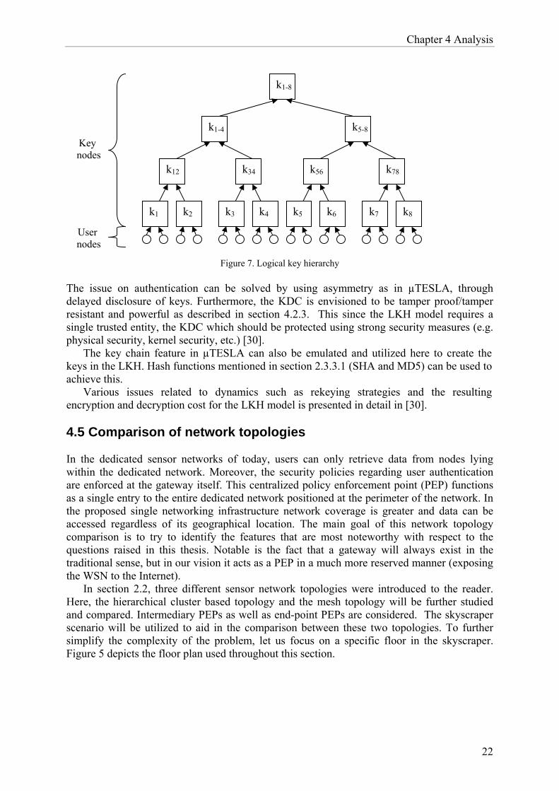
Table 1. Comparison existing wireless technologies .............................................................. 29 Table 2. Description of message types..................................................................................... 32 Table 3. Address formats. ........................................................................................................ 32 Table 4. Description of attach types......................................................................................... 32 Table 5. Description of route discovery message types ........................................................... 33

Chapter 1 Problem definition
1
Chapter 1
Problem definition In the future, multiple applications will be deployed on a sensor network or multiple sensor networks and these applications have to be separated from one another. Control of sensors and their data will be made available only to the users with specific access rights. Previous work [11, 12, 13, 15] deals with several localized groups or single users utilizing a sensor network’s infrastructure. However, they do not allow multiple users with different requirements and different rights to utilize these sensor networks at the same time.
This thesis makes no assumptions of whether or not the nodes measuring a certain entity for an application are geographically fixed or if specific users have a monopoly on information from their ‘own’ nodes. Instead accessing nodes located far apart from each other, but still belonging to the same user, is here considered an important case.
Applying traditional network architecture to sensors would result in a dedicated network where sensors and actuators are connected in a network depending on their usage and location [1]. However, this is not always the best approach. An application may require data from nodes outside its own radio range (i.e. multiple hops away) or information belonging to other users. To access this information the various applications wish to share the same infrastructure (mainly for coverage reasons), but the applications must remain isolated from one another for privacy reasons. In [1], Johansson makes the analogy with early operating system security. The similarities are based upon the need to construct a system that allows more than one user to utilize the same underlying resources, in our case the sensor nodes and the sensor network, in a secure way. Hence, a scheme where various applications run on the same infrastructure with several users; but still remain completely isolated from one another is sought.
This requires a key management scheme that selectively distributes keys to the resources to be used as a logical resource. Furthermore, mechanisms for key revocation of compromised nodes and support for dynamic addition of nodes are needed. Thus creating, in effect a logical network where each relevant node is not necessarily directly physically connected, but rather logically connected. Thus, the connection is completely logical and has no relation to the node’s physical location. Special attention is given to dynamic adaptive methods for managing the network, i.e., addition and removal of applications/users. This differs from revocation due to a node being compromised. Reasons for adaptation include the list of authorized users being changed, applications being added/removed, etc.
The question of plausible network topology also arises; here a theoretical comparison between a hierarchical and a flat architecture will be studied. This is interesting because the choice of security architecture and network topology are in a sense mutually dependent [1]. The placement of policy enforcement points (PEP) for data access varies depending on the given topology. Since the security architecture defines the communicating ability between sensor nodes, the two are dependent.
Potential broadcast encryption schemes and/or routing solutions will be proposed. One of these schemes will be implemented and deployed on the proposed sensor network topology

Chapter 1 Problem definition
2
with two applications and three users. The users will access the node’s information from the internet, based on their access rights. This means that the sensor network must be accessible from an external IP based network.

Chapter 2 Introduction
3
Chapter 2
Introduction 2.1 Wireless Sensor Networks With the decreasing price and increasing performance of sensors, wireless sensor networks (WSNs) is a rapidly evolving technology. The silicon chip performance evolution predicted by Gordon Moore in the late 1960’s has led to smaller chips with denser patterns, which has paved the way for more demanding applications. Current WSN applications, range from large-scale environmental surveillance to monitoring the temperature in a room. For the former case, the sensor network would likely be composed of several thousand nodes functioning autonomously, without access to renewable energy resources [2]. A scenario such as this imposes several design constraints when deploying a large-scale sensor network. Application development and user privileges add another dimension, leading to more intricate network privacy configuration issues, further increasing the design complexity. A WSN cannot function in complete isolation; instead it connects to an external network through which the monitoring users can access the information from the nodes [3]. Thus there is a gateway providing the interconnection of the WSN and the external network. When designing WSNs, decisions must be made based on a unified point of view. This standpoint is important, due to the constraints put on the devices from every layer. As Mayer et al. discuss in [8]; when a single sensor network is used for many applications, we must consider energy, routing, Quality of Service (QoS), and security issues. The following sections will introduce the reader to these issues in WSNs, but we begin by presenting some potential application domains for sensor networks.
2.1.1 Potential markets for sensor networks Advancements in miniaturization combined with the decreasing cost of sensor nodes result in a more inexpensive approach to achieve higher resolution and precision of measurements leading to a wider spectrum of new possible sensor applications. The potential range of application areas is immense. It is the applications that set requirements such as self-configurability, wireless multi hop communication, or querying ability in the network. The first requirement, “adhoc-ness”, is directly related to the fact that the network can operate independently, the second occurs because the source nodes are distributed (need not lie within communication range of each other), and the third due to the networking paradigm of the application. Different applications place different requirements on sensor networks. Furthermore, privacy issues with various applications have raised many questions and demands for international standardizations within the WSN domain. Therefore the potential application domain is an important criterion when designing WSNs. However, given a suitable application (which lead to mass demand) privacy issues for consumers would need to be addressed.
Chapter 2 Introduction
4
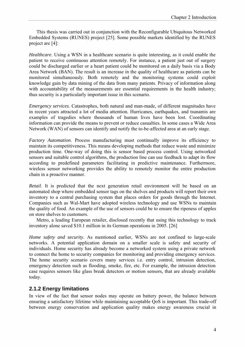
This thesis was carried out in conjunction with the Reconfigurable Ubiquitous Networked Embedded Systems (RUNES) project [25]. Some possible markets identified by the RUNES project are [4]:
Healthcare. Using a WSN in a healthcare scenario is quite interesting, as it could enable the patient to receive continuous attention remotely. For instance, a patient just out of surgery could be discharged earlier or a heart patient could be monitored on a daily basis via a Body Area Network (BAN). The result is an increase in the quality of healthcare as patients can be monitored simultaneously. Both remotely and the monitoring systems could exploit knowledge gain by data mining of the data from many patients. Privacy of information along with accountability of the measurements are essential requirements in the health industry; thus security is a particularly important issue in this scenario.
Emergency services. Catastrophes, both natural and man-made, of different magnitudes have in recent years attracted a lot of media attention. Hurricanes, earthquakes, and tsunamis are examples of tragedies where thousands of human lives have been lost. Coordinating information can provide the means to prevent or reduce casualties. In some cases a Wide Area Network (WAN) of sensors can identify and notify the to-be-affected area at an early stage.
Factory Automation. Process manufacturing must continually improve its efficiency to maintain its competitiveness. This means developing methods that reduce waste and minimize production time. One-way of doing this is sensor based process control. Using networked sensors and suitable control algorithms, the production line can use feedback to adapt its flow according to predefined parameters facilitating in predictive maintenance. Furthermore, wireless sensor networking provides the ability to remotely monitor the entire production chain in a proactive manner.
Retail. It is predicted that the next generation retail environment will be based on an automated shop where embedded sensor tags on the shelves and products will report their own inventory to a central purchasing system that places orders for goods through the Internet. Companies such as Wal-Mart have adopted wireless technology and use WSNs to maintain the quality of food. An example of the use of sensors could be to ensure the ripeness of apples on store shelves to customers.
Metro, a leading European retailer, disclosed recently that using this technology to track inventory alone saved $10.1 million in its German operations in 2005. [26]
Home safety and security. As mentioned earlier, WSNs are not confined to large-scale networks. A potential application domain on a smaller scale is safety and security of individuals. Home security has already become a networked system using a private network to connect the home to security companies for monitoring and providing emergency services. The home security scenario covers many services i.e. entry control, intrusion detection, emergency detection such as flooding, smoke, fire, etc. For example, the intrusion detection case requires sensors like glass break detectors or motion sensors, that are already available today.
2.1.2 Energy limitations In view of the fact that sensor nodes may operate on battery power, the balance between ensuring a satisfactory lifetime while maintaining acceptable QoS is important. This trade-off between energy conservation and application quality makes energy awareness crucial in

Chapter 2 Introduction
5
WSNs. Therefore, energy limitation issues are of great research interest, especially optimizing usage of energy resources to either maximize energy conservation/minimize energy drainage [27, 28]. However, the assumption that a sensor node exclusively operates on battery power is not always true. There exist a number of potential energy sources for WSNs, solar power being one of them; although battery remains the most common energy source.
Communication is considered to be the most energy intensive operation, with sensing and data processing being less energy consuming [27]. In order to promote energy preserving in the communication domain, shutdown based features exist. The node can turn off and on its transceiver, sometimes separately powering on and off sender or receiver mode. Bear in mind that communication energy drainage is not entirely limited to transmitting packets but also includes receiving/listening for packets. The other major energy consumption domain, sensing, also utilizes shutdown features related to the sensor modality; whereas in the computation domain processor energy management is enforced by a variety of means. Processor energy management allows applications to use hardware or software “knobs” to either shutdown or dynamically scale the frequency, supply voltage, or threshold voltage depending on the application’s needs.
Energy consumption is of great interest when designing WSNs due to sensor nodes critically limited energy resources. Therefore each design decision must be made with energy consumption in mind. 2.2 Sensor Network topology In this section we will discuss network topologies of interest for sensor networks. In [1], three different network topologies are presented. Both mesh and tree-based topologies are well-known architectures whereas hierarchical cluster based topology is less familiar to most readers.
Each topology has its advantages and disadvantages depending on the usage scenario. Moreover, different topologies may exist in a single network depending on usage, i.e., different applications and users, management of sensors/network, and so forth [1].
Topologies and architectures of interest for this thesis are described in further detail below. The set of nodes in figure 1a are depicted in the various described sensor network topologies throughout this section. (Figures 1-4)
Figure 1. A set of sensor nodes
Mesh. A mesh network topology employs one of two schemes: full mesh topology or partial mesh topology. In the full mesh topology, each node is connected directly to each of the other

Chapter 2 Introduction
6
nodes. In the partial mesh topology, nodes are only connected to some, but not all of the other nodes. [5]
The main shortcoming of the full mesh topology lies in it not being the optimal topology choice with regard to scalability of sensor networks. The advantage of partial mesh topology is its decentralised architecture, where each node only needs to transmit to its neighbours. This decentralised quality is important because it avoids the single point of failure present in some other topologies. Its robustness and reliability are additional desirable features, for instance if a node is not functioning or disconnected, then its neighbours simply route around it. If the network topology changes frequently, a large fraction of bandwidth will be used merely to maintain the mesh topology, i.e. for routing updates rather than data. The same set of nodes in figure 1 are illustrated having a partial mesh topology in figure 2.
Figure 2. Partial Mesh network.
Tree-based. Tree-based topologies are widely employed in many different networking technologies. In the sensor network domain the leaves connect with an inner node. Nodes higher up in the tree are connected to multiple nodes and act as routers. Communication is always either up or down the tree in this topology [1].
The major disadvantage of this structure is that if one routing node fails, the individual nodes below it in the tree will be isolated from the network. This is due to the fact that a routing node provides the single transmission path to and from the node above and below it. Therefore these routing nodes can be a single point of failure.
Figure 3. Tree based network.
The root is represented by the black node and routing nodes are grey.

Chapter 2 Introduction
7
Hierarchical cluster-based. In this topology the network is divided into sets, forming clusters. Within these clusters some nodes may be more capable than others nodes. These more capable nodes function as controllers, also called cluster heads. A key management scheme that implements this structure will be presented in section 3.3.
The nodes within a cluster communicate with each other through their cluster head. The cluster head represents the entire cluster to other cluster heads. For example, a node from cluster A cannot communicate directly with a node in cluster B, without going through cluster heads A and B. The topology inside the cluster could be any one of the previously mentioned topologies or even recursive hierarchical clusters.
This cluster-based topology can create a hierarchical architecture making such sensor networks more scalable than the previous mentioned topologies. Figure 4 illustrates a network consisting of five cluster heads (black nodes) connected to less capable nodes (transparent nodes).
Figure 4. Hierarchical cluster based network.
The dashed line represents the connection between cluster heads.
2.2.1 Overlay networks An overlay network is defined here as a virtual network overlayed on top of an underlying sensor network. In this virtual network, sensor nodes can be logically connected independent of their geographical position. Overlays have been instrumental especially in distributed systems built on communications infrastructures. However, overlay sensor networks here are quite different due to the highly constrained sensor nodes as compared to the more capable nodes in other domains [8].
Dai et al. [14] present a potential overlay network solutions for unifying sensor networks [14]. Overlay networks such as application-level overlays can differentiate application-specific sensors while integrating geographically distributed WSNs into a single virtual network. This integration is key, as multiple sensor networks can coexist as well as overlap. Dai et al. further note that an application-level overlay permits geographically separated sensor nodes to be unified into a single virtual network via a virtual private network (VPN) [14].
Chapter 2 Introduction
8
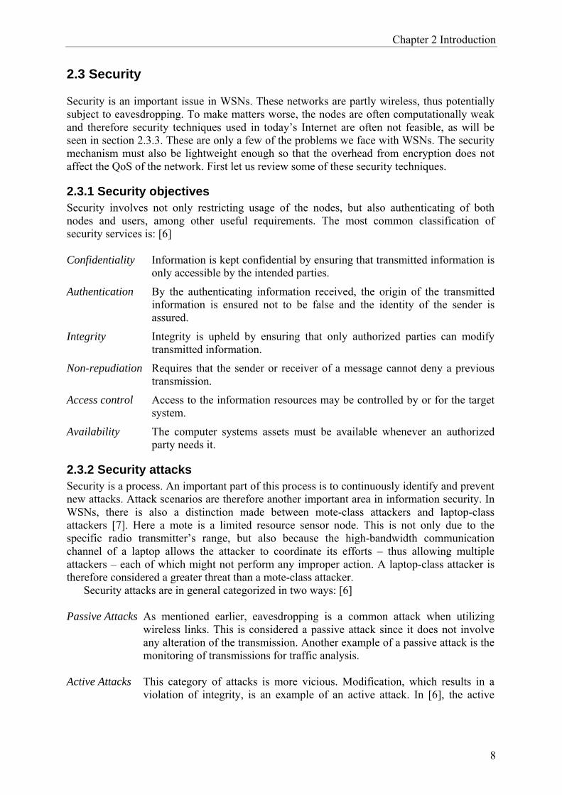
2.3 Security Security is an important issue in WSNs. These networks are partly wireless, thus potentially subject to eavesdropping. To make matters worse, the nodes are often computationally weak and therefore security techniques used in today’s Internet are often not feasible, as will be seen in section 2.3.3. These are only a few of the problems we face with WSNs. The security mechanism must also be lightweight enough so that the overhead from encryption does not affect the QoS of the network. First let us review some of these security techniques.
2.3.1 Security objectives Security involves not only restricting usage of the nodes, but also authenticating of both nodes and users, among other useful requirements. The most common classification of security services is: [6] Confidentiality Information is kept confidential by ensuring that transmitted information is
only accessible by the intended parties.
Authentication By the authenticating information received, the origin of the transmitted information is ensured not to be false and the identity of the sender is assured.
Integrity Integrity is upheld by ensuring that only authorized parties can modify transmitted information.
Non-repudiation Requires that the sender or receiver of a message cannot deny a previous transmission.
Access control Access to the information resources may be controlled by or for the target system.
Availability The computer systems assets must be available whenever an authorized party needs it.
2.3.2 Security attacks Security is a process. An important part of this process is to continuously identify and prevent new attacks. Attack scenarios are therefore another important area in information security. In WSNs, there is also a distinction made between mote-class attackers and laptop-class attackers [7]. Here a mote is a limited resource sensor node. This is not only due to the specific radio transmitter’s range, but also because the high-bandwidth communication channel of a laptop allows the attacker to coordinate its efforts – thus allowing multiple attackers – each of which might not perform any improper action. A laptop-class attacker is therefore considered a greater threat than a mote-class attacker.
Security attacks are in general categorized in two ways: [6] Passive Attacks As mentioned earlier, eavesdropping is a common attack when utilizing
wireless links. This is considered a passive attack since it does not involve any alteration of the transmission. Another example of a passive attack is the monitoring of transmissions for traffic analysis.
Active Attacks This category of attacks is more vicious. Modification, which results in a
violation of integrity, is an example of an active attack. In [6], the active

Chapter 2 Introduction
9
attacks are further divided into four categories: masquerade, replay, modification of messages, and Denial of Service (DoS).
Masquerade Masquerade attacks are based on an adversary
pretending to be someone else or even several identities. This can produce routing inconsistencies or by pretending to be the next hop from the attacked node, the latter is known as a multi-path attack.
Replay The attacker passively captures a data unit and subsequently retransmits it to produce an unauthorized effect.
Modification Part of a message is altered, delayed or reordered to of messages produce an unauthorized effect.
Denial of Services A DoS attack is an event that prevents or inhibits the expected function of communication facilities. This includes attacks such as disrupting or disabling the network by overloading it with messages.
2.3.3 Cryptographic techniques Some of the issues mentioned in previous sections can be resolved using physical security. Physical security means literally isolating the network access from external devices that could pose a threat. However, this method is impractical, as isolating a network results in limited network coverage or defeats the purpose of the sensor network altogether. The most widely used technique besides physical security to secure communication channels is cryptographic security. This section covers the two dominant cryptographic techniques namely: symmetric-key encryption and public-key encryption. Symmetric-key encryption: Secret-key, or symmetric-key, encryption uses a single key. Both parties share a secret-key and can therefore decrypt the encrypted message using this key. The main disadvantage with using symmetric keys is the lack of scalability. For instance assume that node u shares a pairwise secret key with every other node in the network. If there are N nodes in the system, each node u stores N-1 unique secret keys yielding a total of N(N-1)/2 secret keys [9]. This scales quadratically and puts severe constraints on a sensor node’s limited memory if N becomes large. As always, a second dilemma lies in distributing these keys in a secure manner.
The advantage with this technique is that it takes less time to encrypt and decrypt a message using a secret-key than a public-key, due to the relative simplicity of the algorithm. The Data Encryption Standard (DES) and the Advanced Encryption Standard (AES) are two examples of symmetric key algorithms. Public-key encryption: Public-key, or asymmetric, encryption uses two different keys, a public and a private key. For instance, a public-key can be used to encrypt a message that only the intended recipient can decrypt with its private key. The advantage of this is that we no longer have a shared secret-key between the users. However, the scheme has a major disadvantage, which is the complexity of the actual algorithm. This is an important detail particularly with regard to WSNs, as the node’s computational power is limited. Given this limitation and the fact that implementing asymmetric encryption requires either dedicated cryptographic hardware on the sensor node or software encoding of the mathematical

Chapter 2 Introduction
10
functions ~3-5 orders of magnitude slower than symmetric encryption; asymmetric encryption applied on WSNs is difficult to justify [16]. Another limitation that affects the usage of public key encryption is that of storage. A typical public key encryption key is around ~10 times the size of its symmetric counterpart. In addition, the key needs to be transmitted when in use, which requires extra bits to transmit. This is especially demanding in a network where the key is updated often e.g. revoking/adding several users to different groups. Otherwise the transmitted key may be used for the lifetime of the nodes. RSA and Diffie-Hellman are two widely utilized popular asymmetric encryption algorithms. However, Diffie-Hellman is predominately considered to be a key exchange agreement protocol whereas RSA is an algorithm for public-key encryption. 2.3.3.1 Hash functions A cryptographic hash function is a fundamental building block in modern cryptography. Menezes et al. [18] define such a hash function as a computationally efficient function mapping binary strings of arbitrary length to binary strings of fixed length. The probability of a randomly chosen string being mapped to a particular n-bit hash value is 2-n. An additional requirement is that the mapping should be one-way. This property signifies that the hash should be easy to compute in the forward direction, but not vice versa. Hence, a hash function is chosen such that it is computationally infeasible to find an input x given y, where h(x)=y [18]. This is known as the one-way property. The other important properties of hash functions are second preimage resistance and collision-resistance. A hash function is second preimage resistant provided it is computationally infeasible to find a x’ such that h(x)=h(x’), given a input x where x≠x’. The collision-resistant property is true if it is computationally infeasible to find two distinct values x and x’ such that h(x’)=h(x). Secure Hash Algorithm (SHA) is a set of hash functions. SHA-1 is the most employed function in this family. The Message Digest algorithm 5 (MD5) is a hash algorithm belonging to another set of hash functions. The usage of hashing in cryptography lies primarily with digital signatures and data integrity. Hash functions are commonly used to implement a message authentication code (MAC), this is of particular interest in the sensor network security domain. A cryptographic MAC protects the integrity and validates the authenticity of the message. The algorithm is basically a cryptographic hash function that maps a secret-key together with an input message to a keyed-hash message authentication code (HMAC). The recipient, who knows the same secret-key, can verify the HMAC by doing the same computation and comparing the result with the HMAC received. Computationally speaking, hash functions are not as demanding compared to the cryptographic schemes presented in section 2.3.3. A notable fact with the hash functions mentioned is that, as of 2005, several security flaws have been identified in both MD5 and SHA-1. The security weaknesses are related to the collision resistant property of hash functions, and two different messages can be found that map to the same hash value using considerably fewer operations than previously thought. MD5 is more seriously affected than SHA-1.

Chapter 2 Introduction
11
Figure 5. Wireless Automatic Meter Reading.
The figure depicts Chipcon’s vision for wireless collection of utility data, also known as Automatic Meter Reading (AMR). In this single infrastructure, several users exist, raising non-trivial privacy and integrity issues discussed in this thesis - although they merely have a single application gateway. [34]
This figure appears with the permission of Texas Instruments.

Chapter 3 Background
12
Chapter 3
Background 3.1 Related Work Most of the articles published on sensor network security so far assume that there is one user running a single application, whereas this thesis deals with employing cryptography methods to allow multiple users running numerous applications on the same infrastructure, all separated from each other. This is reflected by the fact that the articles studied on key management tend to be geographically divided and do not deal directly with our specific problem. However, an interesting idea is presented in [10] that could be extended to our case. It involves using a tree-based approach to securely distribute keys to distinct nodes. Nodes lying in different geographical areas could be logically connected using this method. In a position paper, Steffan et al. propose scoping in WSN as a solution to handling multi-purpose WSNs [17]. The distinction between nodes based on different applications is mentioned; for instance an environmental monitoring application does not use the same sensors as a tracking application, but may wish to use these nodes for coverage reasons. In sensor networks, the idea of scoping is useful to define and delimit groups of applications. The paper also briefly discusses using overlay structures for implementing communication policies, which could be used for the distribution of encryption keys or discovery of a routing tree. Benenson et al. [20] make a distinction between inside and outside security. Outside security is defined as security between the WSN and outside users meaning the subscribers of the WSN whereas inside security deals with secure communication between sensors and their respective gateways, i.e. within the WSN. Furthermore, a robust scheme focused on user authentication (outside security) is presented in [21]. However, our focal point will be on linking these two notions resulting in a secure connection between the outside users and application-specific nodes, i.e. combining both outside and inside security.
To date, a number of widely recognized key management schemes exist for WSNs, four of which are presented below. The objective of these schemes is secure communication between nodes, i.e. inside security, whereas our problem concerns using cryptographic methods for separating applications and restricting access to only approved users. Nevertheless, the key distributing methods could prove to be valuable when designing a key distribution scheme for our case. 3.2 SPINS Security Protocols for Sensor Networks (SPINS) [11] was one of the pioneering papers on security for sensor networks. It lays a foundation using two building blocks: the Secure Network Encryption Protocol (SNEP) and a “micro” version of the Timed, Efficient, Streaming, Loss-tolerant Authentication (µTESLA). SNEP is a security protocol for unicast communication. The broadcast authentication scheme TESLA, provides source origin

Chapter 3 Background
13
authentication using only symmetric primitives. Source origin authentication is achieved by delayed authentication and ensures that the data received originated from the claimed source and was not changed en route.
Prior to designing these building blocks, four guidelines were given: data confidentiality, data authentication, data integrity, and data freshness.
3.2.1 SNEP The SNEP protocol is designed for two-party communication. It offers several useful properties. Many of these properties can be derived from the fact that SNEP utilizes a counter. The counter helps to generate semantic security; as for each encryption the counter value is incremented leading to different encryptions for the same data. This property prevents eavesdroppers from deducing the plaintext from the corresponding ciphertext. SNEP authenticates data via a MAC, thus the receiver can be assured of the identity of the sender. Freshness is another property that SNEP offers. The receiver knows that the data was sent after the previous authenticated data; based on the lower counter value, thus if the current data is also authenticated, then freshness is assured. However, this constitutes weak freshness since it only offers relative ordering and provides no delay information.
Note that the sender does not have to send the counter state since the counter is kept at each end point. This counter value also helps prevent the replay of old data messages.
3.2.2 µTESLA Like TESLA, µTESLA provides source authentication for broadcast communication. This is a non-trivial task mainly due to the fact that public key methods are considered computationally infeasible on sensor networks, and a pure symmetric key solution would enable all involved nodes to act as the authenticated sender of the broadcast transmission, since they all hold the same symmetric key. µTESLA avoids this by introducing asymmetry through a delayed disclosure of symmetric keys, which results in an efficient broadcast authentication scheme [11]. Key chains are generated in the gateway using a public one-way function. The gateway acts as a key distribution centre (KDC), i.e. a trusted third party. It distributes and shares distinct keys with every node. The nodes are loosely time synchronized with the gateway for key disclosure purposes. The algorithm is briefly described below:
First, the gateway computes a keyed MAC key over the packet, using a key which at that instant is secret. All packets sent within an epoch are authenticated with the same MAC key. The receiver is assured that the MAC key is known only by the gateway. However, authentication for the packets sent in the i-th epoch can only be done in the (i+1)-th epoch due to the one-way property of the key chain. The procedure for achieving this feature is:
(i) A random key k is generated and kept in the gateway. (ii) A key chain is created and stored in the gateway. The keys in the chain are based
on k such that ki = hash( ki+1 ). (iii) Packets sent in the i-th epoch are authenticated using ki, which is released in with
the packet delivery in (i+1)-th epoch. Note that the release allows the recipient to authenticate all previous sent packets, since ki-1=hash( hash( ki+1 ) ).
Therefore the packets are stored in the node’s buffer upon receipt, and remain there until the time of key disclosure when the receiver can authenticate the previous epoch’s key and validate the sender. The delayed key disclosure mechanism provides an asymmetry property useful especially for broadcast, but this incurs an authentication delay.

Chapter 3 Background
14
3.3 LEAP The Localized Encryption and Authentication Protocol (LEAP) [12] was designed based on the fact that different messages transmitted between sensor nodes have different security requirements and that a single keying mechanism is not sufficient to meet all of these requirements. To resolve this LEAP supports the possibility of four different keys – an individual key shared with the gateway, a pairwise key shared with another sensor node, a cluster key shared with multiple neighbouring nodes, and a group key that is shared by all the nodes in the network. The keys are utilized depending on whom the node is communicating with.
1. Individual key. The individual key is used for securing the communication between the gateway and the node. Therefore every node has a unique key that is only shared with the gateway. This unique key can for example be used to compute MACs for sensor readings that only the gateway can verify the authenticity of or for delivering new keys.
2. Pairwise shared key. LEAP uses the pairwise key for securing communication that requires privacy and source authentication. The pairwise key is shared between a node and the other node to which it wishes to communicate.
3. Cluster key. The cluster key is used for securing local broadcast messages, e.g., routing control information. A node and all its neighbours, together composing a cluster, share a key.
4. Group key. The group key is globally shared and can be considered a group/network wide key. It is used by the gateway to encrypt messages that are due to be broadcast to the whole group. This puts a severe constraint on the periodical updates of the group key since compromising only one node opens the whole group for attack from an adversary.
3.3.1 Local Broadcast Authentication Authentication schemes in sensor networks must be lightweight due to processing and communication limitations. Local broadcasting is common in sensor networking whether it is for distributing routing control packets, supporting passive participation, etc. Secure authentication of a local broadcast is therefore important. LEAP handles this by utilizing an AUTH key only known by a node’s neighbours. This AUTH key is a segment of the one-way key generated by every node. The AUTH keys are attached to the message and sent using the pairwise shared key to each neighbour. On receipt the node can verify the AUTH key based on commitment (the first key transmitted) or last received AUTH key. This is possible since the keys are disclosed in the reverse order from their generation.
In [12], a comparison is made with SPINS; especially its broadcast authentication scheme µTESLA. µTESLA is not considered to be suitable for local broadcast, as it does not provide immediate authentication. A node has to wait a certain predefined interval before receiving the MAC key to perform authentication of the received packets; as compared to LEAP’s use of the one-way key chain based authentication that allows an instant verification. 3.4 LiSP The Lightweight Security Protocol (LiSP) is a security protocol designed for large-scale networks with limited resources [13]. The scheme decomposes the network into clusters with
Chapter 3 Background
15
group heads, like the hierarchical cluster based topology described earlier. In this group-based architecture, the group heads are each a key server (KS). This KS serves the surrounding nodes in the cluster (acting as clients). The server’s functions are similar to those of the gateway in SPINS.
LiSP’s hierarchy defines two keys, a temporal key (TK) for encrypting/decrypting data packets; and a master key (MK) that is sensor specific and used for unicasting the TKs to the sensors [13]. The MKs are stored in the sensor’s hardware.
3.4.1. Temporal Key Management The TK management scheme is thoroughly described in [13]. The manager runs on the KS and handles the distribution and revocation of TKs. The main challenges mentioned in [13] lies in maintaining an efficient, reliable, and secure distribution of TKs to nodes and switching between new TKs without disrupting ongoing data transmissions. Since LiSP uses symmetric encryption, both communication parties require the same key to decrypt messages. The scheme accomplishes this by distributing the TKs well in advance. All the sensors buffer store a copy of the group’s TKs. The authenticity of the received TKs is verified by detecting and restoring the missing TKs. Similar to [11], LiSP also uses a one-way key sequence for recovery of lost keys. Three control packets exist for coordinating the TK management. They are the InitKey, UpdateKey, and RequestKey. The InitKey is used to initiate refreshment of TKs. The packets are unicast by the KS to the group member whenever it wants to reconfigure its parameters. The UpdateKey packet contains the current TK and is periodically broadcast to all group members. The RequestKey is generated when a node fails to receive TKs within the predefined time interval; this packet is sent by individual nodes requesting the current TK. 3.5 PIKE The Peer Intermediaries for Key Establishment (PIKE) [15] scheme differs substantially from the previously described schemes in that it is based on a flat architecture. There is no KDC; instead PIKE uses peer sensor nodes in the network as trusted intermediaries to perform key establishment with neighbours. This means that there is no single point of failure that an attacker can target unlike in schemes with KDCs, KSs’ or gateways. Chan and Perrig mention in [15] the lack of scalability in existing key-distribution schemes as the main reason why the PIKE protocol was developed.
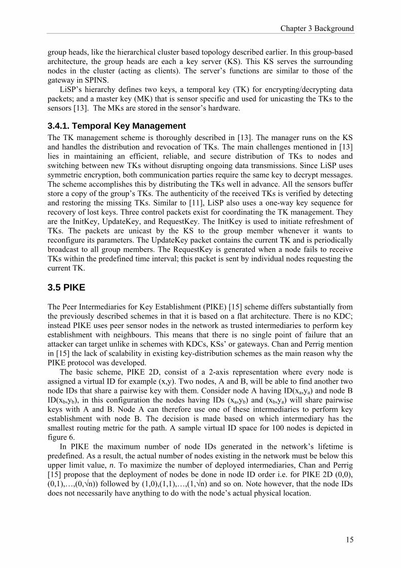
The basic scheme, PIKE 2D, consist of a 2-axis representation where every node is assigned a virtual ID for example (x,y). Two nodes, A and B, will be able to find another two node IDs that share a pairwise key with them. Consider node A having ID(xa,ya) and node B ID(xb,yb), in this configuration the nodes having IDs (xa,yb) and (xb,ya) will share pairwise keys with A and B. Node A can therefore use one of these intermediaries to perform key establishment with node B. The decision is made based on which intermediary has the smallest routing metric for the path. A sample virtual ID space for 100 nodes is depicted in figure 6.
In PIKE the maximum number of node IDs generated in the network’s lifetime is predefined. As a result, the actual number of nodes existing in the network must be below this upper limit value, n. To maximize the number of deployed intermediaries, Chan and Perrig [15] propose that the deployment of nodes be done in node ID order i.e. for PIKE 2D (0,0), (0,1),…,(0,√n)) followed by (1,0),(1,1),…,(1,√n) and so on. Note however, that the node IDs does not necessarily have anything to do with the node’s actual physical location.

Chapter 3 Background
16
Newly established keys can further function as intermediaries to perform key establishments. However, using newly established keys could weaken the security significantly [15]. In the basic setup a single node is used as an intermediary. Hence the first generation key is dependent on one intermediary node’s security. Once that link is established, it can be used to establish a link with a neighbouring node, by using a second-generation key. The second-generation key is established via two first-generation keys making it dependent on three intermediary nodes’ security. This increasing security dependency makes the connection exponentially more vulnerable to node compromise. To remedy this, Chan and Perrig recommend in [15] that some kind of limitation is put on the number of dependencies on any edge node.
PIKE 2D can be further extended to a three-dimension space as is described in [15], resulting in at most two intermediaries. However, simulations [15] show that the dimension increment results in a scheme less resilient against active attacks although achieving a lower communication and memory overhead.
00 01 02 03 04 … 0910 11 12 13 14 … 1920 21 22 23 24 … 2930 31 32 33 34 … 39
.
.
.
.
.
.
.
.
.
.
.
.
.
.
.
.
.
.
90 91 92 93 94 … 99
Figure 6. Virtual ID space In this virtual ID space for 100 nodes, the reader can see how for example
node 01 can employ node 91 to aid in a key establishment with node 99.[15]

Chapter 4 Analysis
17
Chapter 4
Analysis 4.1 Description of scenarios Johansson [1] introduces two scenarios in which the user|application problem is clearly identified. The scenarios will be presented to the reader in the following sections.
4.1.1 The Skyscraper A skyscraper is a tall building with many stories. On every story there are apartments, offices, restaurants, etc. The apartments, offices, and restaurants will probably have different owners. This leads to the existence of several domains within the skyscraper that belong to different owners. A WSN is installed in the building that has full coverage throughout the entire skyscraper. In reality this WSN consists of many smaller sensor networks installed for specific purposes. These could be burglar alarms, thermometers, fire alarms, water meters, sensors keeping track of open doors, which lamps are turned on, when plants need to be watered, the tension in the walls, and also actuators controlling sprinklers, lamps, and door closers.
In a traditional architecture the sensor network would be divided into specific purpose-oriented networks. Instead we propose an architecture where the WSN functions as a single network and where different sensors nodes can use each other as relay points if nothing else. The network benefits from this increased coverage, for example if a node is broken the neighbouring nodes could route around it regardless of the kind of sensor, thus the network arrears to be a single networking infrastructure. Another reason for this architecture is that different owners may be interested in the same value. Consider the case of the skyscraper’s caretaker being the user. The caretaker is interested in the temperature sensor value (application) of all the apartments in the skyscraper. The caretaker could make a sensor query throughout the skyscraper since the network’s coverage is skyscraper-wide. A similar scenario is in the case of an emergency, for instance if a certain section of the skyscraper is on a fire. The location information will be retrieved from a data-centric-like query which would require access to the entire building. Dedicated networks must in this case co-operate and process this request even if they are belonging to different owners. On the other hand, merging sensor networks into a larger WSN also introduces several problems. Maintaining privacy of data implies that certain information should only be accessible to the owner and other authorized users. A resolution of this issue is of specific interest for this thesis.
4.1.2 The Cargo ship A cargo ship is used for transporting commercial freight from point A to point B. The ship’s freight is transported in containers. These containers are equipped with a RFID reader and sensors measuring environmental information. The average temperature or humidity level in a container are examples of what constitutes environmental information. A container may

Chapter 4 Analysis
18
contain goods belonging to different users. The goods are also equipped with RFID tags and sensors. The RFID tags are used to keep track of the location of the goods. The sensors on the goods monitor that their parameters are kept at the correct value. An example of this could be a food distributor verifying the temperature of its cargo in transit. A radio connection between the ship and a satellite interconnects the sensor networks to the outside world. The satellite link is unreliable and expensive and usage of it should therefore be kept to a minimum. Three observations are made in this scenario:
1. Surveillance of cargo should be local. This follows from the fact that usage of the satellite link must be minimized.
2. The satellite is a centralized point of failure on the ship since it is the only mean of communications with the outside world.
3. The owner of the goods must be tolerant to delays and disruptions. The first two observations require that sensor networks with different owners and applications are interconnected to some degree. Another reason for keeping surveillance of the cargo local is for efficiency. Using the satellite link to transmit monitoring information to the home company who in turn sends it to the ship is unnecessary. This monitoring could instead be performed on the ship itself, using the same sensors as in the former case. In this scenario, local surveillance could minimize the use of the expensive and error prone satellite link. Satellite networks generally have higher bit-error rates than terrestrial networks [36]. This is especially expensive when used with TCP, since the TCP control congestion mechanism considers every packet loss as an indicator of congestion and as a consequence reduces the congestion window. The fact that there is only one satellite link generates additional constraints in this scenario. The company who is shipping the goods may not trust the shipping company, i.e. it may not trust it to not modify the sensor data. Consider the case where the company is a food distributor and the sensed data is temperature. There could be an incentive for the ship crew to alter the temperature data, for instance to match acceptable values set by the company. Therefore data received by the company must be both confidentiality and integrity protected. The third observation is due to the fact that an intermediate storage point is needed somewhere between the sensor nodes and the company. The intermediate storage point is used proactively to overcome the loss of information due to the communication disruptions caused by the error prone satellite link. Its function resembles that of a store-and-forward (S-F) and mitigates the usage of the nodes’ limited energy for retransmission. However, using an intermediate storage point will not reduce the volume of data been sent. 4.2 The Model A cryptographic scheme is used to resolve the issues identified in the scenarios. It creates an overlay and utilizes the fact that different users and applications are associated with each other. The model proposed also introduces a new entity, the manager. The manager administers a given space and is geographically constrained. It is the manager that authenticates the user and grants access to its nodes. The user and application form a secure virtual group once the managers involved have authorized the user. As mentioned earlier, the scheme is not restricted to a given location. Therefore separate parts of a manager’s domain are each virtual subgroup. For a user to be able to access nodes in several managers’ domains requires access authority from the each manager. Consequently, these secure virtual subgroups form a single secure virtual group and the user sees only a single group of nodes.
Chapter 4 Analysis
19
An introduction to each of these roles is given below to give a base description of each involved party’s role in this model.
4.2.1 Application The application domain for sensor networks is very broad. It ranges from health care to military scenarios. In a WSN, an application is node-dependent since the sensor on the node defines and restricts its physical sensing capabilities. For example, a humidity sensor node can not take an active role in an application involving motion detection, but it could play a passive role by relaying motion-information. Thus, an application is very much dependent on the node’s sensor(s). Note that a node is not confined to a single application due to its sensor, i.e. a temperature sensor node could be used for several temperature related applications. Each application is presumed to have a unique key.
4.2.2 User Sensor nodes themselves fill no special purpose without a user, who is in need of the sensed information. For the systems which we will consider, this is a prerequisite for a fully functioning system. The user’s role is consequently of great interest, but allowing multiple simultaneous users also creates a number of difficulties. Consider the case of the cargo ship, the users might be competing companies who should not be able to access information from nodes belonging to each other. If company A could access company B’s cargo status information the result could be disastrous for company B’s business. Hence, privacy between different users’ applications is an important issue in this thesis. Each user is presumed to have a unique key.
4.2.3 Manager The manager is the owner of its domain. In the cargo scenario the manager could be a shipping company owning one or several containers. In the skyscraper scenario it could be an apartment owner or a restaurant owner. The common feature in these scenarios lies in the control of nodes.
A manager of a domain, a physical area, most likely owns the sensor nodes lying or being deployed in its area and the sensing information of the nodes entering the area. The manager has access control lists that define a policy regarding access rights. For instance, consider the case where user U1 is retrieving data from nodes in manager M3’s domain using application A2. Subsequently user U1 also wants to retrieve data from A2 nodes in manager M4’s domain. This cannot be done unless U1 is listed in manager M4’s access control list for A2 nodes. To be able to access these nodes U1 has to negotiate access rights for the selected A2 nodes running in manager M4’s domain.
This in fact clearly illustrates the non-geographically bounded property of users in this scheme. User U1 is only limited based upon its access rights, which are determined by the various managers. In this definition, a manager is instead geographically bounded. This since the manager is the “owner” of the nodes in a physical area. For instance, a manager in the skyscraper scenario would correspond to the owner of a room. The manager is therefore, geographically bounded to this physical area.
In reality, the manager could be an application running on each node in a secure memory space. This creates a parallel hardware enforced protected domain where the manager-application is executed and is totally inaccessible to all but privileged users in contrast to the non secure memory space where the node specific applications are executed. Access control of the running applications in the non-trusted/protected memory space is handled by the manager-application. The result is the protected memory space authorizing rights for the non

Chapter 4 Analysis
20
secure memory space. This example would in fact add constraints such as tamper proof/tamper resistant nodes as the manager runs on a protected memory space from which it authorizes rights to the non-secure memory space. Access rights can further be distinguished into read or write capability: a certain user may be given reading rights while another altering (write) rights. This can best be illustrated in the cargo ship scenario where the owner of the goods in the container may require that the ship’s crew only have reading capabilities. In this way the crew can monitor the goods for any abnormalities, but can not alter the applications to benefit their own purposes.
4.3 Design guidelines Designing a key distribution/management involves a set of loose rules/design considerations or guidelines. The guidelines exist to ensure that the keying mechanism is reliable and robust. A key management scheme designed according to these guidelines can in our case ensure that the key distribution, rekeying, and policy enforcement is done in a secure and efficient way. Mitra [19] presented six important features and requirements to bear in mind when designing a framework for scalable secure multicasting. The generality of the design principles in [19] result in some of them holding even for this case, when designing a secure method for multicasting the user keys to selected group of nodes and managing the dynamics of the groups. The requirements that are to be considered for this key distribution/management scheme are:
1. Scalability: Sensor nodes will likely be deployed in large quantities having various physical sensing capabilities. The assumption is that these large numbers of nodes will be used by multiple applications and multiple users, hence leading to a need for scalability. Secure multicasting to the various groups of sensor nodes belonging to an application|user is difficult mainly due to its non-geographical bounded feature. The groups may have closed (i.e., static) or highly dynamic membership depending on the properties of the application.
2. Robustness: The scheme should not collapse exponentially even after a few nodes comprised. This applies for both mean malicious attacks and also network disruptions. Networks disruptions are often caused by the failure of a single point of failure, therefore such single points of failure should be avoided (as pointed out earlier in section 2.3.2) by sharing single networking infrastructure instead of several separate dedicated sensor networks.
3. Security Objective Independence: The scheme presented does not make any assumptions on specific security objectives. It is a framework for securing key management for dynamic groups of sensor nodes and therefore does not need to define what specific security objectives can be met.
4. Security Protocol Independence: No specific cryptographic algorithms or protocols are presumed for the given scheme. The scheme should be completely independent of underlying security protocol.
5. Communications Protocol Independence: The scheme should be able to be implemented as an overlay, independent of the underlying communication protocol. The only requirements from the overlay is functioning communication between nodes in the WSN, that is to say the scheme can be implemented on any network supporting various communication patterns such as unicast, local broadcast, or global broadcast.

Chapter 4 Analysis
21
4.4 Broadcast encryption scheme As mentioned in section 3.3.1, local broadcasting is common in sensor networks. Local broadcasting usually involves broadcasting to all nodes within a neighbourhood (a one-hop broadcast). This requires that all sensors in the local neighbourhood know the same key, and support for this exists in for instance LEAP [12].
In our scenario, the nodes in an overlay are however not necessarily within a single neighbourhood. This requires that traffic will be routed through non valid overlay nodes. If we want to broadcast messages in the whole overlay and still keep the message away from non-overlay members, we must therefore encrypt messages with a key which is known by the all the nodes in the overlay, but no other sensors. What we need is thus a protocol to establish a common key among a specific set of sensors. This can of course be solved with naive methods, but if the group of sensors is very large, small changes in the overlay set may lead to a very high overhead in messages needed to re-key the remaining sensor nodes. Broadcast encryption is a term for a large number of different methods used to distribute the group key to the set of sensors that should be allowed to receive the broadcast message. The word broadcast encryption might actually be somewhat misleading, since it generally deals with the problem of key-management for large groups, and the encryption itself is carried out in the traditional way.
The scheme we envision should include a broadcast mechanism for distributing and managing the session keys with all relevant nodes. Furthermore, enlisting a broadcast encryption scheme would definitely ease the revocation and addition of nodes process. Revocation and addition of users require the entire group to be rekeyed. Moreover, if the application key is compromised, the entire application overlay must be rekeyed in order to satisfy the security objectives.
Two broadcast encryption schemes that are of interest in efficiently aiding in this are Logical Key Hierarchy (LKH) and Subset Difference (SD). In the LKH model [31], keys are logically distributed in a tree rooted at the KDC. The KDC stores all the keys in the key tree. The tree makes rekeying more efficient compared to a naïve approach – asymptotically you need O(log n) messages in order to re-key a group of n users, compared to the naïve approach of O(n) messages. One of the drawbacks with LKH is that it is a stateful protocol, meaning that the ability to decrypt the current broadcast is dependent on the previous transmissions. The SD model is however stateless.
Given the characteristics of a sensor network, it promotes the usage of SD since nodes often are not active e.g. sleeping. A rekeying protocol that demands the active presence of all nodes such as a stateful protocol is therefore not the best choice. However, the stateful protocol is best suited for groups with low dynamics and frequent rekeying updates [30]. Moreover, we only have to store one SD tree in the sensor network in order to distribute whatever secret to the whole network.
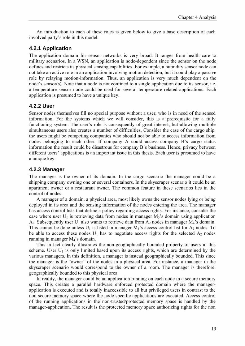
An example of how the LKH scheme could be used follows (figure 7). In the tree graph two nodes are defined, k and u. The u-nodes represents the users and the k-nodes the keys. The required storage space for these nodes is O(h), h being the height of the tree. Each u-node corresponds to the unique key lying in a node. The root node functions as the overlay key since all nodes within the same overlay has access to that key.
Chapter 4 Analysis
22
Figure 7. Logical key hierarchy
The issue on authentication can be solved by using asymmetry as in µTESLA, through delayed disclosure of keys. Furthermore, the KDC is envisioned to be tamper proof/tamper resistant and powerful as described in section 4.2.3. This since the LKH model requires a single trusted entity, the KDC which should be protected using strong security measures (e.g. physical security, kernel security, etc.) [30].
The key chain feature in µTESLA can also be emulated and utilized here to create the keys in the LKH. Hash functions mentioned in section 2.3.3.1 (SHA and MD5) can be used to achieve this.
Various issues related to dynamics such as rekeying strategies and the resulting encryption and decryption cost for the LKH model is presented in detail in [30].
4.5 Comparison of network topologies In the dedicated sensor networks of today, users can only retrieve data from nodes lying within the dedicated network. Moreover, the security policies regarding user authentication are enforced at the gateway itself. This centralized policy enforcement point (PEP) functions as a single entry to the entire dedicated network positioned at the perimeter of the network. In the proposed single networking infrastructure network coverage is greater and data can be accessed regardless of its geographical location. The main goal of this network topology comparison is to try to identify the features that are most noteworthy with respect to the questions raised in this thesis. Notable is the fact that a gateway will always exist in the traditional sense, but in our vision it acts as a PEP in a much more reserved manner (exposing the WSN to the Internet).
In section 2.2, three different sensor network topologies were introduced to the reader. Here, the hierarchical cluster based topology and the mesh topology will be further studied and compared. Intermediary PEPs as well as end-point PEPs are considered. The skyscraper scenario will be utilized to aid in the comparison between these two topologies. To further simplify the complexity of the problem, let us focus on a specific floor in the skyscraper. Figure 5 depicts the floor plan used throughout this section.
k2 k3 k4 k5 k6 k1
k34 k12 k56
k1-4
k1-8
k5-8
k78
k7 k8
User nodes
Key nodes

Chapter 4 Analysis
23
Figure 8. A floor in the skyscraper.
Sensor nodes are deployed in the various spaces belonging to different owners. The full mesh topology differs from the hierarchical cluster based topology due to its non-hierarchical architecture. In full mesh topology, all nodes act as routers as well as end points. In this topology the single points of failures are minimized or avoided depending on the density of nodes. Therefore communication reliability of a network with a mesh topology is greater than that of a network having a hierarchical cluster based topology. In the hierarchical cluster based topology there exist several clusters in which a cluster head governs. The cluster head is the routing node and all traffic heading to and leaving from the cluster passes through it. Here the cluster head is also assumed to be a more powerful node in comparison to the other nodes in the cluster.
Considering these two topologies with respect to the problem definition results in two different situations. In a full mesh topology we have a network in which a node can communicate with all nodes within its communication range whereas in hierarchical cluster based topology we have a network consisting of clusters. Each cluster has a cluster head which is used as the cluster’s ‘gateway’ to the rest of the network. With the full mesh topology, policy must be enforced at every node due to the network accessibility. However, in the hierarchical cluster based topology the traffic is routed from cluster head to cluster head until it reaches its destination cluster. At its destination cluster the head forwards the packet to the end points. Here the PEP can be moved to a higher level since all traffic to nodes within a cluster must pass through the cluster head. Therefore the PEP in this case can be enforced in the more powerful cluster head.
In figure 9, the nodes on the floor of the building have been connected into a partial mesh topology. This figure clearly depicts the full connectivity of nodes in mesh networks. All nodes can communicate with each other regardless of which space they lie in. In this case the PEP must be in each and every node. The end point PEP assures that the access control is enforced, but at the same time puts more constraints on each of the resource limited nodes.

Chapter 4 Analysis
24
Figure 9. The nodes on the floor in a partial mesh topology.
All nodes within radio range can communicate with each other.
In figure 10, the nodes have been connected into a hierarchical cluster based topology where each room, office, etc. belongs to a specific cluster. Note how communication to nodes lying in a cluster always must go through the cluster head (black nodes). In this case the PEP can be moved from the end points into the cluster head. Using intermediary PEPs allows much of the security previously enforced in the end points to be enforced in the intermediaries instead. This lifts some of the heavy requirements on the resource weak end point nodes. Instead security in every node can be up kept using the technique described in section 4.2.3. However, this decreases reliability since the WSN now depends on the cluster heads for both communication and to act as PEPs.
Figure 10. The nodes on the floor in a hierarchical cluster based network.
4.6 Security overlays In this section, the hierarchical cluster based topology is considered along with the proposed security overlay’s role. Instead of using the gateway at the perimeter of the network as a security enforcement point, the proposal here is that an application gateway is established within the network. The result is that the former gateway functions merely as a bridge between the Internet and the WSN world. Access control is enforced within the network

Chapter 4 Analysis
25
creating multiple overlays within a WSN, each depending on a user’s rights for usage of applications. An example involving a single application is presented below and a proof of concept will be implemented in the following chapter. Figure 11 depicts the application overlay for application X.
Figure 11. In this figure the nodes on the floor are again depicted in a hierarchical cluster based network. Note that all nodes belonging to application X are red with the application gateway being maroon. The grey zone marks the application overlay.
Figure 12 depicts how the user/application overlay is distributed for User 1 and for User 2. Note that the users connect to an application gateway lying in the WSN (shown in figure 11) and within the application overlay there are two separate user overlays that are governed based on the user’s access rights to nodes in the application overlay.
Figure 12. Within the application X overlay lies two different User/application X overlays. The set of nodes belonging to application X are further layered to the set of nodes that user 1 has access to (blue zone) and the set of nodes that user 2 has access to (green zone). Certain assumptions are made about the application gateways. These are assumed to be considerably more powerful nodes, capable of performing asymmetric cryptographic operations. This assumption means that communication between the users and the application
Application Gateway
AX overlay
U2 | AX overlay
U1 | AX overlay

Chapter 4 Analysis
26
gateway may occur via a public-key protected communications manner. Protocols such as the Secure Sockets Layer (SSL) [33] or Transport Layer Security (TLS) [32] can be used to secure communication over the Internet. With a SSL/TLS connection any amount of data can be sent securely between the external user and the internal application gateway. Addressing issues at the application gateway will be discussed in the evaluation chapter. Within the application overlay, a symmetric key scheme is utilized. A broadcast encryption scheme is used to manage the dynamics of each application overlay. The shared infrastructure separated by overlays is a layered approach (figure 12). Clearly, this approach results in mutually isolated virtual distributed environments (at application level) employing the resources of the shared infrastructure (at physical level).

Chapter 5 Implementation
27
Chapter 5
Implementation 5.1 Hardware platform
The planned implementation stage is realized and is to utilize sensor nodes developed at the University of California, Berkeley. The Telos Rev B [23] nodes are composed of a Texas Instruments MSP430 low power microcontroller running at 8 MHz with 48 Kbytes of Flash ROM and 10 Kbytes of RAM, a Chipcon CC2420 [22] IEEE 802.15.4 compliant transceiver for wireless communication capable of operating at communication rates up to 250kbps. The integrated on-board sensors measure humidity, light, and temperature. The sensors used throughout this thesis were those related to light sensing. The two default light sensors integrated on-board the motes are for sensing photosynthetically active radiation (PAR) and the entire visible spectrum (TSR). The motes are battery driven and powered by two AA batteries. There exists a USB controller from FTDI to transfer data from the host computer for both programming and communication. The internal antenna has a coverage range of 50 meters indoors and close to 125 meters outdoors. Figure 13 depicts the front/back and a functional block diagram of the Telos Rev B mote.
Figure 13. Front/back and a block diagram of the Tmote module [23].
This figure appears with the permission of Moteiv Corporation.

Chapter 5 Implementation
28
5.2 Contiki Operating System
The OS provided with the Telos Rev B motes is TinyOS. However, the implementation in this thesis was carried out on motes using the Contiki operating system [24]. Contiki is a lightweight event-driven operating system developed especially for memory constrained communication-oriented devices at the Swedish Institute of Computer Science (SICS). The operating system supports TCP/IP communication using its µIP stack.
The Contiki operating system allows code to be dynamically downloaded for each sensor at run-time. Furthermore, the programs and services downloaded and running on the nodes can be unloaded at run-time.
A routing protocol for multi-hopping and dynamically route discovery was developed for the simulation environment. The details of this routing protocol are given in the next section. 5.3 Routing protocol The routing protocol in the Telos motes port of Contiki, at the beginning of this thesis was close to obsolete. Thus, prior to designing the overlay structure, a routing protocol including a dynamic route discovery scheme needed to be developed and implemented for the nodes. Moreover, a distinct routing layer was added to the stack. Compared to the OSI layer abstraction, the WSN stack is much more intertwined. An example of this property is that nodes are often controlled (at hardware level/physical layer) for energy purposes through software knobs at the application layer.
The decision on which topology to implement, was based on the suitability for the two previously described scenarios. Since the hierarchical cluster based topology seemed most suitable for the scenario, ergo it is implemented here. However, prior to discussing the route discovery mechanism a brief introduction to the ZigBee protocol stack is given as we have used the ZigBee protocol stack for this work.
Figure 14. The entire network stack for this implementation, including the added routing layer.
5.3.1 ZigBee Platform The IEEE 802.15.4 standard also popularly known as ZigBee was approved in 2003. ZigBee is aimed at low power devices, hence it is also known as a Low Rate-Wireless Personal Area Network (WPAN) with a transmission rate around 250 kbps. The ZigBee Platform is however not quite the same as IEEE 802.15.4 as it also defines the higher layers of the protocol stack, from network to application; whereas the IEEE 802.15.4 standard only defines the lower protocol layers (physical and MAC). With respect to security, ZigBee supports hardware
Physical
Routing
Network
Application
IEEE 802.15.4
ZigBee Platform
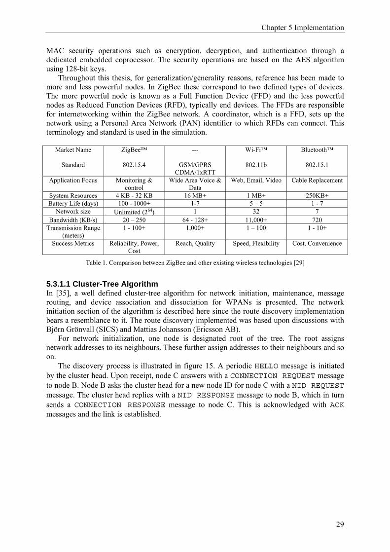
Chapter 5 Implementation
29
MAC security operations such as encryption, decryption, and authentication through a dedicated embedded coprocessor. The security operations are based on the AES algorithm using 128-bit keys.
Throughout this thesis, for generalization/generality reasons, reference has been made to more and less powerful nodes. In ZigBee these correspond to two defined types of devices. The more powerful node is known as a Full Function Device (FFD) and the less powerful nodes as Reduced Function Devices (RFD), typically end devices. The FFDs are responsible for internetworking within the ZigBee network. A coordinator, which is a FFD, sets up the network using a Personal Area Network (PAN) identifier to which RFDs can connect. This terminology and standard is used in the simulation.
Market Name
Standard
ZigBee™
802.15.4
---
GSM/GPRS CDMA/1xRTT
Wi-Fi™
802.11b
Bluetooth™
802.15.1
Application Focus Monitoring & control
Wide Area Voice & Data
Web, Email, Video Cable Replacement
System Resources 4 KB - 32 KB 16 MB+ 1 MB+ 250KB+ Battery Life (days) 100 - 1000+ 1-7 5 – 5 1 - 7
Network size Unlimited (264) 1 32 7 Bandwidth (KB/s) 20 – 250 64 - 128+ 11,000+ 720
Transmission Range (meters)
1 - 100+ 1,000+ 1 – 100 1 - 10+
Success Metrics Reliability, Power, Cost
Reach, Quality Speed, Flexibility Cost, Convenience
Table 1. Comparison between ZigBee and other existing wireless technologies [29]
5.3.1.1 Cluster-Tree Algorithm In [35], a well defined cluster-tree algorithm for network initiation, maintenance, message routing, and device association and dissociation for WPANs is presented. The network initiation section of the algorithm is described here since the route discovery implementation bears a resemblance to it. The route discovery implemented was based upon discussions with Björn Grönvall (SICS) and Mattias Johansson (Ericsson AB).
For network initialization, one node is designated root of the tree. The root assigns network addresses to its neighbours. These further assign addresses to their neighbours and so on.
The discovery process is illustrated in figure 15. A periodic HELLO message is initiated by the cluster head. Upon receipt, node C answers with a CONNECTION REQUEST message to node B. Node B asks the cluster head for a new node ID for node C with a NID REQUEST message. The cluster head replies with a NID RESPONSE message to node B, which in turn sends a CONNECTION RESPONSE message to node C. This is acknowledged with ACK messages and the link is established.

Chapter 5 Implementation
30
Figure 15. The cluster-tree algorithms multi hop cluster setup procedure
5.3.2 Hierarchical cluster-based network Implementing this topology required several components including a routing mechanism. The nodes need to discover their neighbours. Contiki-2.x lacked support for both route discovery and multi-hopping. Both needed to be implemented to allow the infrastructure to support run-time behavior such as dynamic routing capability. Each cluster has a PAN ID unique to its neighbourhood/cluster. Multi-hop capability was added by exploiting the destination field in the µIP header. At the routing layer, the packet’s destination is extracted from the µIP header (network layer) and used to perform a lookup in the routing table. Packets are forwarded based upon the route found in the routing table. If there is not route to this destination in the routing table, the packet is forwarded to the node’s parent.
5.3.2.1 Multi cluster route discovery Creating a dynamic network requires a dynamic route discovery mechanism. When each node is first powered on the routing table is initialized and connectivity with its neighbours is established. Nodes emit a beacon to enable their neighbours to discover them. The objective here is to establish a hierarchical cluster-based topology. In the initial link setup, a set of routing messages are exchanged once a beacon packet is received.
Node A (CH) Member Node B Member Node C
HELLO
CON REQ
NID REQ
Set node C as Child of B
HELLO
NID RES
CON RES
Set node C as Child
ACK
ACK
Link Established
Set node B as Parent

Chapter 5 Implementation
31
Figure 16. Figure of route discovery process
Four route establishment packets were defined (based upon discussions) including a beacon packet, as illustrated in figure 15. The BEACON is sent by a node to announce its existence. Depending on the receiving node’s connection status a connection REQUEST message is replied. If the identity of the node is not found in the beacon-sending node’s routing table, it is added and a connection ACCEPT message is sent to the node. The ACCEPT message results in the recipient adding the node’s ID to its routing table. Note that the REQUEST message only can be sent if the BEACON is from an attached node. Otherwise, the receiving node answers with a BEACON, provided it is attached to a cluster. This scheme creates a single hop cluster. To extend to the multi-hop cluster case, an INFORM message is defined that informs a node’s parent as soon as a routing entry is made in the routing table. These packets are presented in detail below, see figures 16 and 17. The header is depicted in 4-byte sections since it is customary for TCP/IP. The packets follow the standard 802.15.(4) header. A brief description of each field is given below the corresponding message format.
Figure 17. Message format for beacon packets Length The length of the header (8 bits) is defined in this field.
Attach address
Source address
Length
ID
FC0 FC1 PAN
Destination
Cluster head (CH) Member Node B Member Node C
BEACON
REQUEST
ACCEPT
Node B set as child
CH set as parent BEACON
REQUEST
ACCEPT
Node C set as child
INFORM Node B set as route for Node C
Node B set as parent
32 bits

Chapter 5 Implementation
32
FC0 The type of the packet. FC0_TYPE_BEACON | FC0_INTRA_PAN. (See Table 2)
Type Description
0 Beacon 1 Data 2 Acknowledgement 3 MAC_CMD 4 Routing
Table 2. Description of message types. Types 0-3 are ZigBee defined types.
FC1 Indicates the address formats in the packet. In our case both addresses are
16 bits. (See Table 3)
Bit Source Destination
Mask 0x0c 0xc0 0 0x00 0x00 16 0x08 0x80 64 0x0c 0xc0
Table 3. Address formats. (ZigBee defined)
PAN ID Each cluster has a unique PAN ID. The PAN ID identifier is 16 bits long.
Source address The source address is in this implementation is based on the last 16 bits of the host’s IP address. E.g. for the IP address 172.16.0.2, the source address in the beacon message format is 0x0200 in network byte order (see the function Host to Network Short - HTONS).
Destination As with the source address, the destination address is defined by the last 16 3address bits of the packet’s IP destination address. Since the destination of the
beacon is a local broadcast the IP address would be 255.255.255.255, so the destination address is 0xffff for the beacon packet. Note that packets with the destination address 0xffff are heard by all nodes.
Attach Attached status field lets the receiving node know the status of the sender. The field is either 0x01 for an attached node or 0x00 for an unattached node. (Table 3)
Type Description
0 Unattached node 1 Attached node
Table 4. Description of attach types
The attach status field in the beacon packet is of importance for creating the hierarchical cluster-based topology. A node receiving a beacon packet checks its own attached status, as well as the packet’s attach field status before replying to the beacon. If the node sending the beacon is unattached the attachment process begins. Otherwise, if the beacon comes from an attached node, the beacon is discarded.

Chapter 5 Implementation
33
Figure 18. Message format for routing packets Length Header length
FC0 Type of packet. FC0_TYPE_ROUTING | FC0_INTRA_PAN
FC1 Address formats in the packet. Addresses are 16 bits for routing messages.
PAN ID ID for the entire PAN, 16 bits long.
Source address 16 bit source address, based on the last byte of the host IP address.
Destination 16 bit destination address. Last byte of the destination IP address. address
Type Three route discovery messages are defined. Type 0x01 is the request message. Type 0x02 is the accept message. Type 0x03 is the inform message. (Table 4)
Type Description 1 Request message. Sent by a node requesting to be
attached. 2 Accept message. Sent by a node accepting the
request node’s request 3 Inform message. Sent by a member node to its
parent to inform that a node below him has been attached.
Table 5. Description of route discovery message types
End destination In the case of a type 0x03 message, the end address is stored here (16 bits
long) and conveyed to the cluster head and parents for route table updates.
Distance For type 0x03 messages, the distance to end address is kept in this field. Each parent adds an increment to this field.
Figure 18 depicts a few of the topologies attained after routing discovery. Logically, the topology in the far left and center of figure 14 are desired for use in the simulation environment. Achieving this topology is dependent on the range nodes lie in respect to each other. Since this is a dynamic routing discovery scheme no prior hard coding attempt was made to ensure any one of these specific topologies statically. Therefore, the broad tree is just as likely as the one-hop depth tree. In chapter 6 the similarity between the access control list nodes and the application gateway is discussed. Note in figure 4 that the hierarchical cluster based network consists of clusters made up one-hop depth trees.
Length FC0 FC1 Sequence
Destination address
PAN Id
End destination
Distance
Type address
Source address Destination
Length
ID
FC0 FC1 PAN
32 bits
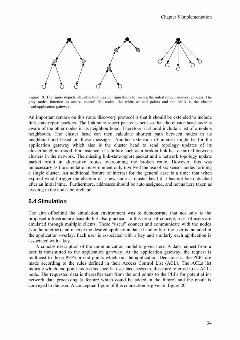
Chapter 5 Implementation
34
Figure 19. The figure depicts plausible topology configurations following the initial route discovery process. The grey nodes function as access control list nodes, the white as end points and the black is the cluster head/application gateway. An important remark on this route discovery protocol is that it should be extended to include link-state-report packets. The link-state-report packet is sent so that the cluster head node is aware of the other nodes in its neighbourhood. Therefore, it should include a list of a node’s neighbours. The cluster head can then calculate shortest path between nodes in its neighbourhood based on these messages. Another extension of interest might be for the application gateway which also is the cluster head to send topology updates of its cluster/neighbourhood. For instance, if a failure such as a broken link has occurred between clusters in the network. The missing link-state-report packet and a network topology update packet result in alternative routes overcoming the broken route. However, this was unnecessary as the simulation environment only involved the use of six sensor nodes forming a single cluster. An additional feature of interest for the general case is a timer that when expired would trigger the election of a new node as cluster head if it has not been attached after an initial time. Furthermore, addresses should be auto assigned, and not as here taken as existing in the nodes beforehand. 5.4 Simulation The aim of/behind the simulation environment was to demonstrate that not only is the proposed infrastructure feasible but also practical. In this proof-of-concept, a set of users are emulated through multiple clients. These “users” connect and communicate with the nodes (via the internet) and receive the desired application data if and only if the user is included in the application overlay. Each user is associated with a key and similarly each application is associated with a key.
A concise description of the communication model is given here. A data request from a user is transmitted to the application gateway. At the application gateway, the request is multicast to those PEPs or end points which run the application. Decisions at the PEPs are made according to the rules defined in their Access Control List (ACL). The ACLs list indicate which end point nodes this specific user has access to, these are referred to as ACL-node. The requested data is thereafter sent from the end points to the PEPs for potential in-network data processing (a feature which could be added in the future) and the result is conveyed to the user. A conceptual figure of this connection is given in figure 20.

Chapter 5 Implementation
35
Figure 20. Conceptual figure of the simulation environment.
As in previous figures, the black node is the application gateway, the grey node – access control list nodes, and white nodes – end point nodes.
5.4.1 Applications The applications developed for this simulation are purely of academic interest. Each application utilizes data from a light sensor. The usage of the information from the sensor depends on the how the application interprets the value in the client.
The primary objective is that data is processed and retrieved in a suitable manner. The light sensors reply to requests based on the application key. Application key one corresponds to application one and application key two to application two etc.
5.4.2 Overlay The overlay consists of three different program codes depending on which node is used. One program runs in the application gateway node, another program implements the access control lists (ACL) nodes, and the third program executing in the end point nodes, processes the requests and retrieves data from the sensors. There is a large correlation between these three programs, especially between the application gateway and the access control list nodes. The application gateway is in direct connection to the user. Users communicate via to the application gateway by sending a UDP packet. The application gateway in return multicasts this UDP packet to every ACL node in the application overlay by several sequential unicasts. The ACL node forwards the UDP packet to the relevant end point node(s) that process the request and reply with the requested application data. The reply is conveyed to the ACL node for further in network processing or simply forwarded to the gateway node. In the current implementation, the application gateway was the same node as the traditional gateway. This is naturally not a requirement, and the application gateway need not be a fixed node in the WSN, as discussed further in chapter 6. However, in this simulation the traditional gateway does not function simply as a (to-the-user transparent) bridge since this node also functions as a router. In the version of Contiki that was used, data is tunnelled from
Internet
WSN Users
Traditional gateway

Chapter 5 Implementation
36
the computer connected to the traditional gateway node through an interface, TUN0. TUN0 is the tunnelling interface between the computer connected to the gateway node. In that sense, here the computer connected to the traditional gateway is always present as more than just a mere bridge. Therefore, even if the application gateway is separated from the traditional gateway, the traditional gateway will still be more than a transparent connection between the WSN and the Internet.
5.4.3 Client The model incorporated several users attempting to retrieve data from the WSN. A client emulating a user was developed. The client is a Java application. (figure 21)
The Java client provides a Graphical User Interface (GUI) to the user, where the user can choose between the two applications described in section 5.4.1. Each application is linked to an application key and each user to a user key. A user key concatenated with the application key uniquely identifies the user and application. The rights of this user to utilize this application are validated at the ACL-node.
To simplify matters, the user communicates with this application using a fixed port (in this case UDP port number 44444 was used). UDP request packets are sent including a return address. The purpose of this is for the return address to be stored in the packet for end-user delivery. Since all nodes in this implementation have IP addresses, every intermediate communication (e.g. end point to ACL-node or ACL-node to Application gateway, vice versa) can be considered as sequential end to end communications. The source address is changed at every authorization intermediary so there must exist some form of storage of the real end-point’s IP address as the return address. This because, authorization checks are done at application level resulting in “new” transmissions at these nodes (ACL, Application gateway) when using uip_udp_send_conn(len, conn). In order to overcome this problem, authorization intermediaries should check user access rights and forward packets without changing the original source address.
Several active users are emulated by using multiple simultaneously running user clients. The implementation was tested with two users accessing two applications.
Figure 21. In this figure, two users are simulated. User 1 has access to both Application 1 and Application 2, whereas User 2 only has access to Application 1. For that reason, we see in the prompt that Application 2 data accessed by User 2 results in a No packet received reply, as the packet is dropped at the ACL-node. (Not ICMP message since it is dropped at application level)

Chapter 6 Evaluation
37
Chapter 6
Evaluation In this chapter concerns with the migration from the traditional WSN architecture to the proposed architecture with overlays are discussed. Issues that arise with the usage of IP in WSN are focused on. Furthermore, an analysis of the implemented route discovery protocol is given. IP capability is essential for providing a seamless integration between the internet and WSNs. However, the communication paradigm of IP (end-end communication) does not match the needs of WSNs. IP only functions well among a subset of nodes, such as cluster heads. The communication model used here is end-end from the external user to the cluster head in the WSN, but not within the cluster itself. This enables users to connect to an overlay without an intermediary node (via a traditional gateway). Moreover, there must exist some form of internal addressing within the WSN/overlay itself. Current architectures resolve this by re-addressing/mapping the request at the perimeter of the WSN (traditional gateway). For example, a request is mapped at the traditional gateway, then forwarded to the appropriate nodes within the WSN using non-IP communication. This differs from the traditional model in which the traditional gateway merely functions as a bridge to the WSN, i.e. network convergence. In our architecture we retain the traditional gateway (to some extent) as it still functions as a PEP. This gateway permits valid users to retrieve data from WSN (avoiding DoS attacks from non-valid users). This can be implemented as in the simulation (where all users are known to the traditional gateway) and the overlays govern what applications a user can access. In today’s internet architecture we see IP used over quite heterogeneous networks, further promoting its usage within WSNs as well - even if not to a full extent for all communication. The µIP stack used in Contiki and the implementation is a viable way of using IP in this highly constrained environment. As it is proposed here that cluster heads act as application gateways. They have globally unique IP addresses so as to be reachable for external users. The application gateway need not be a single fixed node in an overlay; all cluster heads within the overlay can function as application gateways. This means that the ACL nodes are also required to have unique externally accessible addresses. Consequently, each ACL node within the overlay can function as an application gateway if required. End point nodes are only reachable through their ACL node, avoiding the need for a unique address for nodes. By using overlays we separate the security problems of storing all keys in the traditional gateway. Thus, when an application gateway is compromised only the nodes within the overlay need to be rekeyed. Moreover, mapping application gateways to ACL nodes (depending on users/metrics within an overlay) further distributes the effort for rekeying in the case of a compromise. Using a broadcast encryption scheme ensures that this can be done efficiently. In a traditional WSN architecture, a compromised gateway would result in the rekeying of the entire network. A broadcast encryption scheme is additionally supported by the communications paradigm of WSNs. For example, queries for data acquisition are often broadcasted within the WSN, in

Chapter 6 Evaluation
38
our case; broadcasted to a set of nodes belonging to a certain user. This scheme preferably uses nodes with a tamper-resistant component that act as KDCs holding the tree of keys. However, a tamper-resistant component increases the node’s cost leading to a trade-off between price and need. Placement of application gateways is another complex question. Since application gateways in their capability and function are very similar (if not identical) to ACL nodes, we have assumed that ACL nodes within an overlay can act as application gateways depending on their accessibility. The application gateway and ACL nodes are often physically the same type of node. In ZigBee, these are FFD nodes capable of performing public-key cryptography. This assumption together with the fact that each ACL node is accessible to external users enforces the belief that every ACL node can function as application gateways. However, the presumption in this is that external users have prior knowledge of the address of the ACL nodes within an overlay. This is also another reason for a unique IP address for application gateways and ACL nodes. The route discovery protocol implemented here introduced a new set of packets. Route packets were labeled as type 4 packets. These packets are not defined in the ZigBee routing platform specified data packet formats. Route packets are used to establish, and in the future update routes in the WSN. The route discovery is initiated and conducted by the cluster head. Further, if a node needs to send a packet to a node whose address does not exist in its route table; a route discovery is initiated to locate a route to the destination node. Similarities with [35] exist in that the earliest HELLO message is responded to since it is considered to have the strongest possibility of the shortest route to the cluster head. This route to the cluster head is later optimized in [35], but not in my simulation. Comparing figures 15 and 16 illustrates that the sequence of establishing links differ between the two protocols. In my implementation, addresses are not auto assigned by the cluster head as in [35]. Instead they are initially preset by sequentially pressing the reset button (figure 13). Likely metrics used to measure and evaluate the performance of the route discovery protocol are packet delivery ratios in each topology as the network is initiated as well as when nodes are added/removed. A high packet delivery ratio along with low energy consumption is desirable, which introduces energy as a interesting metric (in correlation with packet delivery ratios). Comparison between protocols using measured route discovery time and varying beaconing intervals should not be overlooked. This was tested by a simple ping to the nodes in the cluster to check the performance of the route discovery process. Moreover, (for diagnostics) the sensors LEDs (figure 13) were used to indicate at what stage of the route discovery the node was. This proved valuable due to the unpredictable radio environment. The implementation was simulated in an office environment similar to that of the skyscraper scenario. The cluster head acts as the application gateway to the nodes in the overlay. In a mesh topology every node in the overlay would be required to authenticate and authorize external users. In such a decentralized non-hierarchical topology, it is likely to be costly in terms of power consumption for security measures. Therefore, the route discovery implemented in this thesis creates a hierarchical topology. The use of a hierarchical cluster based topology in this model is superior because it reduces the cryptographic requirements on a large set of nodes in the WSN. Authentication and authorization is performed by a subset of the nodes, the ACL nodes. This can be derived from the fact that network functionality is unevenly distributed in the hierarchical cluster based topology. However on the downside, this architecture restricts the application topology, e.g. a WSN having an underlying hierarchical topology can never truly achieve a full mesh topology at application level with respect to the entire WSN. The ACL nodes become more important nodes due to the unevenly distributed processing. While the mesh topology would

Chapter 6 Evaluation
39
require that all nodes in our model be FFD nodes (handle public-key cryptography and be able to act as application gateways). In this flat architecture much of the network functionality is evenly distributed. An example of this is that all nodes are able to route. The advantage of this topology is that any application topology can be achieved. Moreover, there exists no single point of failure in a mesh topology. Its major shortcoming is that all nodes must be able to authenticate and authorize users (uniformly distributed functionality and every node being an FFD).

Chapter 7 Conclusions and Future work
40
Chapter 7
Conclusions and Future work 7.1 Conclusions
The concept of overlays has been introduced to the wireless sensor network domain. A virtual shared infrastructure, in which all nodes function as relay nodes and potentially end nodes is a potential evolution of WSNs. The thesis further advocates that instead of having dedicated WSNs, we can have dedicated overlays distributed in a single shared WSN infrastructure. This vision is not entirely new, in figure 5 a description of Chipcon AG’s application-specific view on this matter was presented, although without mentioning the problems with this approach. This thesis further proposes a possible resolution using cryptographic schemes and discusses problematic issues (extent of IP capability within the WSN) arising with this. The proof-of-concept simulation demonstrates that placement of PEPs within the WSN instead of the perimeter (traditional gateway) is both plausible and viable but still very hard. There are still many problems that have to be solved, both legal and technological. It is not fully clear yet what the trust model will look like in future applications, and possibly specific applications such as the skyscraper will help defining them. The cryptographic ability and memory capacity of nodes in a WSN will continue to advance, hence there are many different development paths are possible. Time will tell, but new consumer markets will most probably require distributed secure overlay solutions within a single infrastructure, thus there will be a demand for a method to implement them. 7.2 Future work
There needs to be research on:
Trust models Specific architectures (including application gateways, ACL nodes and IP capability) Performance issues of these specific architectures
Research related to performance issues should be conducted. This requires a larger test network than the environment available for this thesis. The use of distributed overlays would consequently lead to a greater interaction between protocol layers that in fact could significantly impact the performance when multiple applications are running and several users active in the WSN. Therefore, research related to energy dissipation due to using user|application overlays is required. Perhaps a broadcast encryption scheme based on a stateless cover such as SD could aid in solving the compartment issues. In that case, it should be stateless due to the nature of nodes in a WSN. Nodes are not always active for energy saving reasons, i.e. they may be sleeping.

41
References [1] Mattias Johansson, Ericsson AB, Unpublished manuscript, May 2005
[2] Deepak Ganesan, Alberto Cerpa, Wei Ye, Yan Yu, Jerry Zhao, and Deborah Estrin. Networking Issues in Wireless Sensor Networks, Elsevier Science, December 2003, page 1
[3] Adam Dunkels, Juan Alonso, Thiemo Voigt, Hartmut Ritter, and Jochen Schiller, Connecting Wireless Sensornets with TCP/IP Networks, In Proceedings of the Second International Conference on Wired/Wireless Internet Communications (WWIC2004), Frankfurt (Oder), Germany, Springer Verlag, February 2004, page 1
[4] András Tóth, Reconfigurable Ubiquitous Networked Embedded Systems brochure, page 3, <http://www.ist-runes.org/docs/brochures/RUNES_brochure.pdf>, accessed September 2005
[5] Search Mobile Computing, Glossary September 2003, <www.searchmobilecomputing.com>, accessed 15 September 2005
[6] William Stallings, Cryptography and Network Security – Principles and practice, Prentice Hall, 2nd edition, 1999
[7] Chris Karlof and David Wagner, Secure routing in wireless sensor networks: attacks and countermeasures, Sensor Network Protocols and Applications, 2003. Proceedings of the First IEEE, 2003 IEEE International Workshop, 11 May 2003, page(s) 113 – 127
[8] Karl Mayer, Björn Grönvall, Janne Riihijärvi, Annikki Welin, Gösta Leijonhufvud, Frank Oldewurtel, Wolfgang Fritsche, Mattias Johansson, Stephen Hailes, Cecilia Mascolo, Mirco Musolesi, and Håkan Hjalmarsson, D4.1 Requirements and Configuration Scenarios, Reconfigurable Ubiquitous Networked Embedded Systems, May 2005
[9] Behrouz A. Forouzan, TCP/IP Protocol Suite, McGraw Hill, Second edition, 2003
[10] Erik-Oliver Blass, Michael Conrad, and Martina Zitterbart, A Tree-Based Approach for Secure Key Distribution in Wireless Sensor Networks, Proceedings of the First REALWSN, 20-21 Jun 2005
[11] Adrian Perrig, Robert Szewczyk, Victor Wen, David Culler, and J.D. Tygar, SPINS: Security Protocols for Sensor Networks, n: Proceedings of the 7th annual international conference on Mobile computing and networking (ACM MOBICOM). ACM Press, 2001, page(s): 189-199.
[12] Sencun Zhu, Sanjeev Setia, and Sushil Jajodia, LEAP: Efficient Security Mechanism for Large-Scale Distributed Sensor Networks, In Proceedings of the 10th ACM Conference on Computer and Communications Security, Washington D.C., October, 2003.
[13] Taejoon Park and Kang G. Shin, LiSP: A Lightweight Security Protocol for Wireless Sensor Networks, ACM Transactions on Embedded Computing Systems, Volume 3 Issue 3, August 2004, page(s):664-660

42
[14] Hui Dai and Richard Han, Unifying Micro Sensor Networks with the Internet via Overlay Networking, Local Computer Networks, 2004. 29th Annual IEEE International Conference on 16-18 Nov, 2004, page(s):571 – 572
[15] Haowen Chan and Adrian Perrig, PIKE: Peer Intermediaries for Key Establishment in Sensor Networks, INFOCOM 2005, 24th Annual Joint Conference of the IEEE Computer and Communications Societies. Proceedings IEEE Volume 1, 13-17 March 2005, page(s):524 – 535
[16] C. S. Raghavendra, Krishna M. Sivalingam, and Taieb Znati, Wireless Sensor Networks, Kluwer Academic Publishers, May 2004, page: 6
[17] J. Steffan, L. Fiege, M. Cilia, and A. Buchmann. Scoping in wireless sensor networks. In Intl Workshop on Middleware for Pervasive and Ad-Hoc Computing (MPAC'04), October 2004.
[18] Alfred J. Menezes, Paul C. van Ooorschot, and Scott A. Vanstone, Handbook of Applied Cryptography, <http://www.cacr.math.uwaterloo.ca/hac/>, accessed 10th October 2005
[19] Suvo Mittra, Iolus: A Framework for Scalable Secure Multicasting, Proceedings of the ACM SIGCOMM 1997, 14-18th September 1997
[20] Zinaida Benenson, Felix Gärtner, and Dogan Kesdogan, An algorithmic framework for robust access control in wireless sensor networks, In Second European Workshop on Wireless Sensor Networks (EWSN), January 2005.
[21] Zinaida Benenson, Nils Gedicke, and Ossi Raivio, Realizing Robust User Authentication in Sensor Networks, Proceedings of the First REALWSN, 20-21 Jun 2005
[22] Chipcon AS, CC2420 – 2.4 GHz IEEE 802.15.4 / ZigBee-ready RF Transceiver, Datasheet, 3 October 2005
[23] MoteIV Corporation, Telos – Ultra low power IEEE 802.15.4 compliant wireless sensor module, Preliminary datasheet, 15 May 2004
[24] Contiki project homepage, <http://www.sics.se/~adam/contiki/>, accessed December 2005
[25] RUNES project homepage, <http://www.ist-runes.org/>, accessed September 2005
[26] CNN Technology, Future looks rosier for RFID, <http://edition.cnn.com/2006/TECH/ptech/03/10/rfid.chips.reut/index.html>, accessed 14 March 2006
[27] G.J. Pottie, W.J. Kaiser, Wireless Integrated Sensor Networks, Communication of the ACM, Volume 5 May 2000, page(s): 51-58
[28] Zach Shelby, Carlos Pomaza-Raez, Heikki Karvonen, Jussi Haapola, Energy Optimization in Multihop Wireless Embedded and sensor networks, International Journal of Wireless Information Networks, Vol 12, No.1. January 2005
[29] How does ZigBee compare to other wireless standards, <http://www.zigbee.org/en/about/faq.asp>, accessed 24 April 2006
[30] Mattias Johansson, Gunnar Kreitz, and Fredrik Lindholm,"Stateful Subset Cover", Editors: Jianying Zhou, Moti Yung, Feng Bao, Lecture Notes in Computer Science,

43
In Proceedings of Applied Cryptography and Network Security: 4th International Conference, ACNS 2006, Springer Berlin / Heidelberg, Volume 3989 / 2006, ISBN: 3-540-34703-8, page(s): 178 - 193.
[31] Chung Kei Wong, Mohamed Gouda, Simon S.Lam, Secure Group Communications using Key Graphs, Department of Computer Sciences, University of Texas at Austin
[32] RFC 4346 The Transport Layer Security (TLS) Protocol v1.1, <http://www.ietf.org/rfc/rfc4346.txt>, accessed 9 May 2006
[33] SSL 3.0 Protocol specifications, <http://wp.netscape.com/eng/ssl3/draft302.txt>, accessed 9 May 2006
[34] Johan Ivarsson, Automatic Meter Reading – Wireless collection of Utility Meter Data, International Congress for Wireless Sensors and Networks, 21 December 2005, slide 10
[35] Ed Callaway (for ver. 0.6) and Masahiro Maeda (for version 0), Cluster Tree Protocol, IEEE P802.15 Wireless Personal Area Networks Project, IEEE, Submitted 30 April, 2001
[36] RFC 2760 Ongoing TCP Research Related to Satellites, < http://www.ietf.org/rfc/rfc2760.txt>, accessed 31 July 2006

44
Appendix A
Acronyms
ACL Access Control List AES Advanced Encryption Standard AMR Automatic Meter Reading BAN Body Area Network CH Cluster Head DES Data Encryption Standard DoS Denial of Service FFD Full Function Device GUI Graphical User Interface HMAC Hash Message Authentication Code IEEE Institute of Electrical and Electronics Engineers IP Internetworking Protocol KDC Key Distribution Centre KS Key Server LEAP Localized Encryption and Authentication Protocol LiSP Lightweight Security Protocol LKH Logical Key Hierarchy MAC Message Authentication Code MD5 Message Digest algorithm 5 QoS Quality of Service PAN Personal Area Network PEP Policy Enforcement Point PIKE Peer Intermediaries for Key Establishment in Sensor Networks RFD Reduced Function Device RFID Radio Frequency Identification RUNES Reconfigurable Ubiquitous Networked Embedded Systems SD Subset Difference SHA Secure Hash Algorithm SSL Secure Sockets Layer TCP Transmission Control Protocol TESLA Timed, Efficient, Streaming, Loss-tolerant Authentication

45
TLS Transport Layer Security µIP Micro Internet Protocol UDP User Datagram Protocol UWB Ultra Wideband VPN Virtual Private Network WAN Wide Area Network WPAN Wireless Personal Area Network WSN Wireless Sensor Networks

www.kth.se
COS/CCS 2006-15