Embed Size (px)
Citation preview
Power System Engineering, Inc. 1
Power System Engineering, Inc.
© 2012 Power System Engineering, Inc. Confidential and Proprietary. Not for reproduction or distribution.
Jeff Triplett
Power System Engineering, Inc.
Web Site: www.powersystem.org
October 25, 2012
Power System
Engineering, Inc.
Distributed Generation Resources
Connected to Distribution Systems
Power System Engineering, Inc.
© 2012 Power System Engineering, Inc. Confidential and Proprietary. Not for reproduction or distribution.
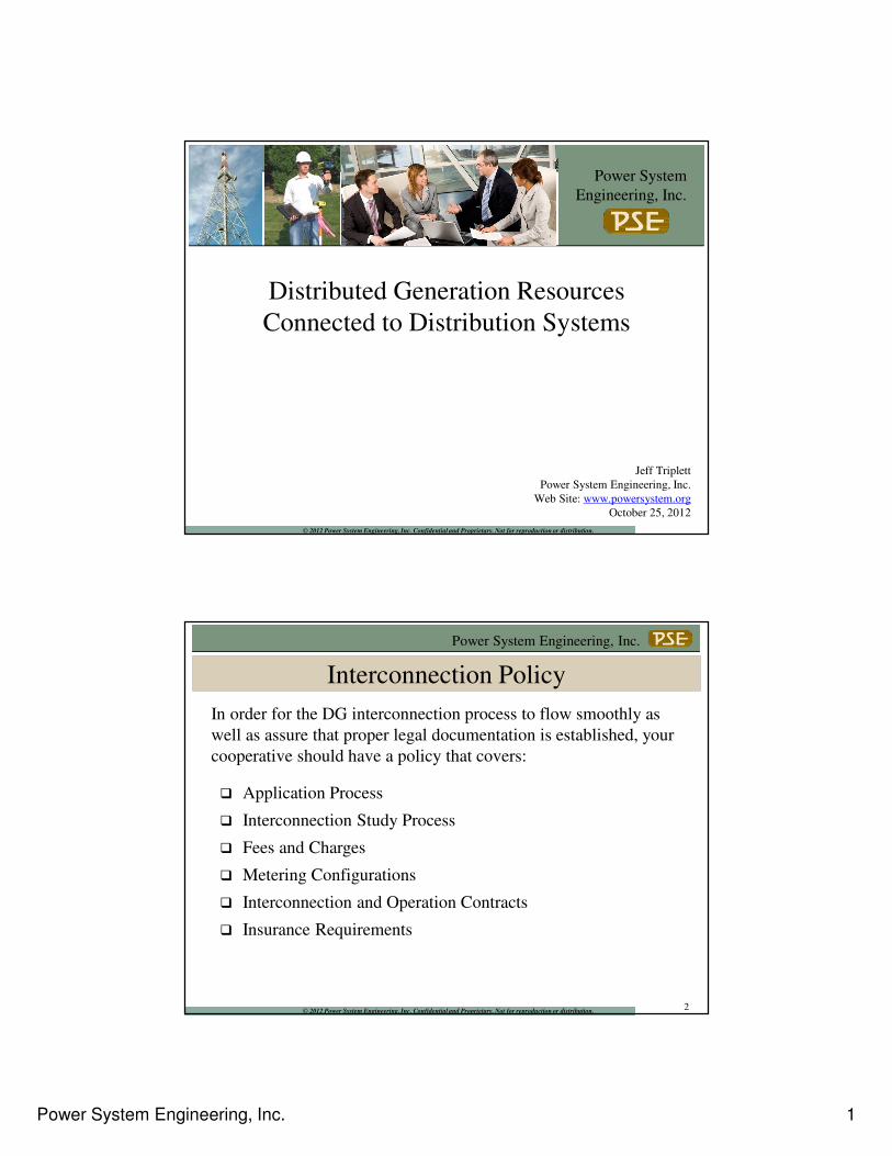
Interconnection Policy
2
In order for the DG interconnection process to flow smoothly as
well as assure that proper legal documentation is established, your
cooperative should have a policy that covers:
� Application Process
� Interconnection Study Process
� Fees and Charges
� Metering Configurations
� Interconnection and Operation Contracts
� Insurance Requirements
Power System Engineering, Inc. 2
Power System Engineering, Inc.
© 2012 Power System Engineering, Inc. Confidential and Proprietary. Not for reproduction or distribution.
Interconnection Contracts
3
Interconnection contracts are required to assure that there is a legal
agreement and understanding between the DG owner and the
cooperative of how the DG facility will be operated and maintained.
Other items covered in these type of contracts include:
� Responsible party
� Limitation of Liability
� Testing
� Right of Access
� Disconnection
� Metering
� Insurance
� Assignment
� Schedule of Facilities
Power System Engineering, Inc.
© 2012 Power System Engineering, Inc. Confidential and Proprietary. Not for reproduction or distribution.
DG Classifications
• From a utility interconnection standpoint, can classify DG systems by type of electrical converter (or type of generator that interfaces the system to the distribution system)
– Synchronous machines
– Induction machines
– Inverters and static power converters
– Double Fed Induction Generator (DFIG)
4
Power System Engineering, Inc. 3
Power System Engineering, Inc.
© 2012 Power System Engineering, Inc. Confidential and Proprietary. Not for reproduction or distribution.
Synchronous Machines
• Produce AC
• Has to be synchronized with the distribution system voltage,
frequency and phase angle
• Requires complex controls
• Real power output (watts) controlled by the governor of the
prime mover
• Reactive power output (VARs) controlled by level of field
excitation
• Controllable power factor
• Significant fault contribution
• Capability for “islanding” to occur
• Commonly used for applications > 750 kW
5
Power System Engineering, Inc.
© 2012 Power System Engineering, Inc. Confidential and Proprietary. Not for reproduction or distribution.
Induction Machines
• Produce AC
• Basic control systems
• Rotational speed has to be higher than that required for exact
synchronism with utility; otherwise, the generator becomes a motor
and consumes power
• Flicker is a concern if machine is started as a motor
• Reactive power has to be supplied by an external source; therefore
poor power factor can be a concern
• Reduced capability for islanding unless sufficient capacitance is in
parallel to provide self-excitation
• Typical applications in modestly rated wind turbines (50 – 750 kW)
6
Power System Engineering, Inc. 4
Power System Engineering, Inc.
© 2012 Power System Engineering, Inc. Confidential and Proprietary. Not for reproduction or distribution.
Inverters and Static Power Converters
• Convert DC or non-synchronous AC to synchronous AC (DC-to-AC or AC-to-DC-to-AC)
• Provide power conditioning
• Controllable power factor on some models
• Used with PV, small wind turbines, fuel cells, battery storage, DC generators
• Less familiarity at the utility level
• Protective functions can be integrated into the inverter (utility may require additional relaying and/or testing capability)
• Limited capability for islanding to occur
• Limited short circuit current capability
7
Power System Engineering, Inc.
© 2012 Power System Engineering, Inc. Confidential and Proprietary. Not for reproduction or distribution.
Inverter Basics
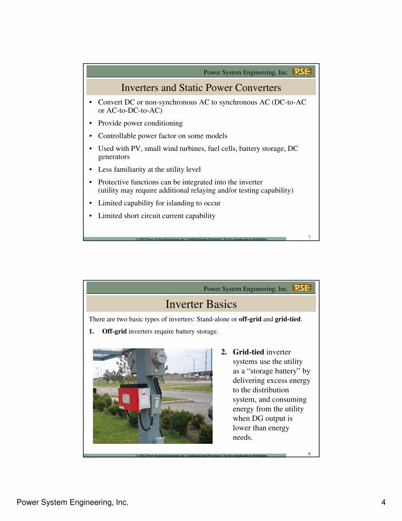
There are two basic types of inverters: Stand-alone or off-grid and grid-tied.
1. Off-grid inverters require battery storage.
2. Grid-tied inverter
systems use the utility
as a “storage battery” by
delivering excess energy
to the distribution
system, and consuming
energy from the utility
when DG output is
lower than energy
needs.
8
Power System Engineering, Inc. 5
Power System Engineering, Inc.
© 2012 Power System Engineering, Inc. Confidential and Proprietary. Not for reproduction or distribution.
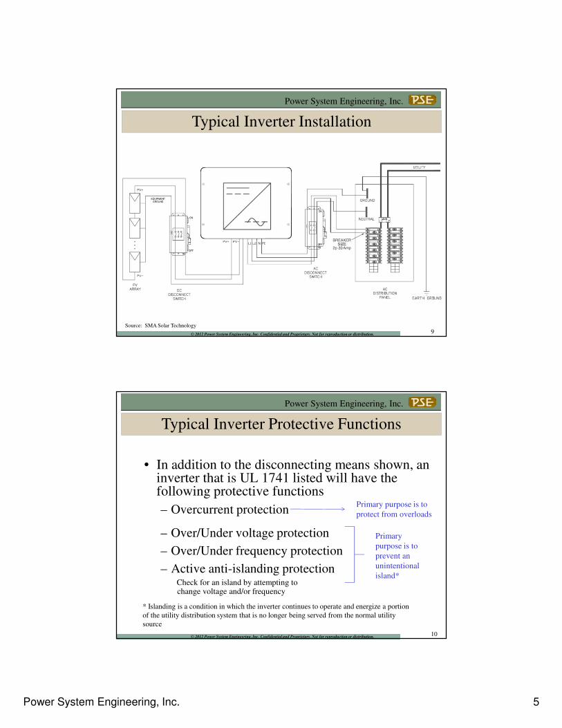
Source: SMA Solar Technology
Typical Inverter Installation
9
Power System Engineering, Inc.
© 2012 Power System Engineering, Inc. Confidential and Proprietary. Not for reproduction or distribution.
• In addition to the disconnecting means shown, an inverter that is UL 1741 listed will have the following protective functions
– Overcurrent protection
– Over/Under voltage protection
– Over/Under frequency protection
– Active anti-islanding protection Check for an island by attempting to change voltage and/or frequency
Primary
purpose is to
prevent an
unintentional
island*
Primary purpose is to
protect from overloads
* Islanding is a condition in which the inverter continues to operate and energize a portion
of the utility distribution system that is no longer being served from the normal utility
source
Typical Inverter Protective Functions
10
Power System Engineering, Inc. 6
Power System Engineering, Inc.
© 2012 Power System Engineering, Inc. Confidential and Proprietary. Not for reproduction or distribution.
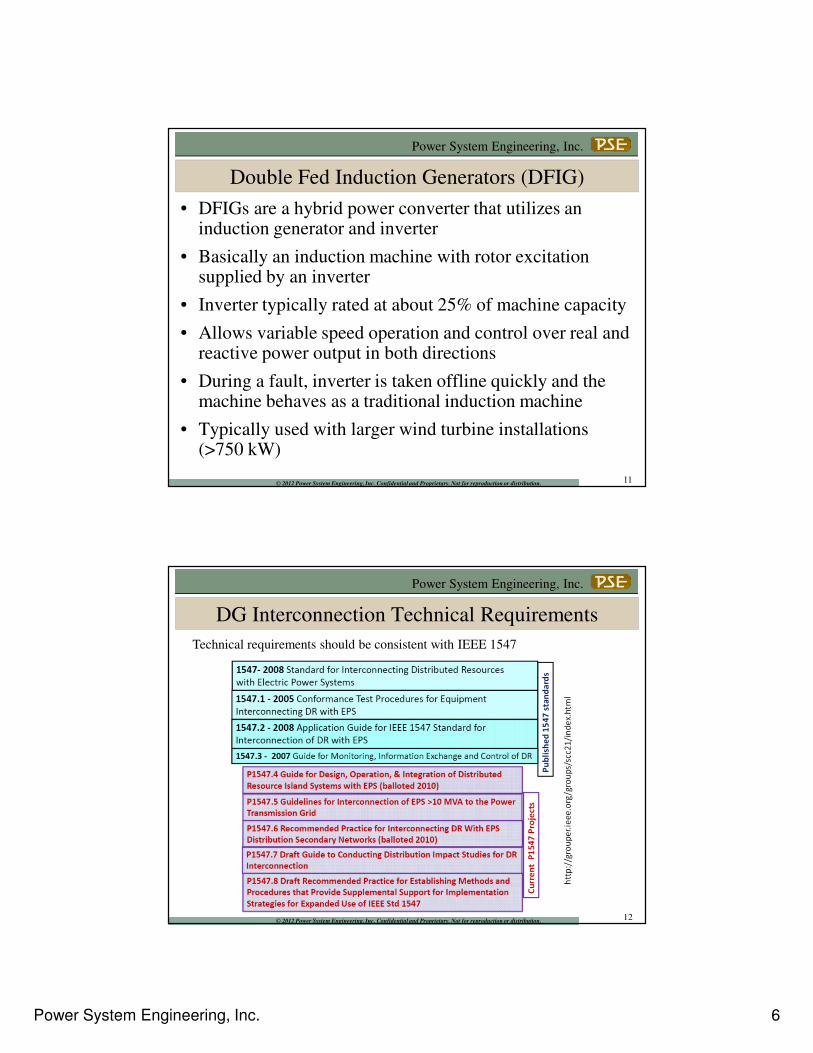
Double Fed Induction Generators (DFIG)
• DFIGs are a hybrid power converter that utilizes an induction generator and inverter
• Basically an induction machine with rotor excitation supplied by an inverter
• Inverter typically rated at about 25% of machine capacity
• Allows variable speed operation and control over real and reactive power output in both directions
• During a fault, inverter is taken offline quickly and the machine behaves as a traditional induction machine
• Typically used with larger wind turbine installations (>750 kW)
11
Power System Engineering, Inc.
© 2012 Power System Engineering, Inc. Confidential and Proprietary. Not for reproduction or distribution.
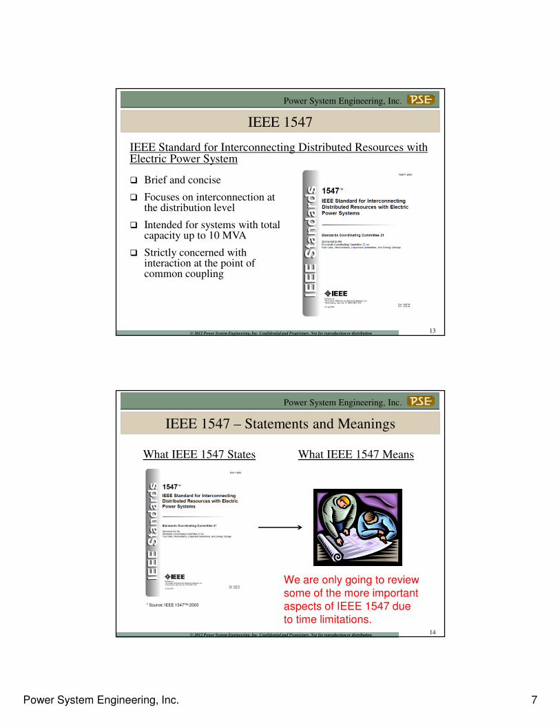
DG Interconnection Technical Requirements
Technical requirements should be consistent with IEEE 1547
12
Power System Engineering, Inc. 7
Power System Engineering, Inc.
© 2012 Power System Engineering, Inc. Confidential and Proprietary. Not for reproduction or distribution.
IEEE 1547
IEEE Standard for Interconnecting Distributed Resources with Electric Power System
� Brief and concise
� Focuses on interconnection at the distribution level
� Intended for systems with total capacity up to 10 MVA
� Strictly concerned with interaction at the point of common coupling
13
Power System Engineering, Inc.
© 2012 Power System Engineering, Inc. Confidential and Proprietary. Not for reproduction or distribution.
IEEE 1547 – Statements and Meanings
What IEEE 1547 States What IEEE 1547 Means
* Source: IEEE 1547TM-2003
14
We are only going to review
some of the more important
aspects of IEEE 1547 due
to time limitations.
Power System Engineering, Inc. 8
Power System Engineering, Inc.
© 2012 Power System Engineering, Inc. Confidential and Proprietary. Not for reproduction or distribution.
IEEE 1547 – Voltage Regulation
“ The DR shall not actively regulate
the voltage at the PCC.”
- and -
“The DR shall not cause service
voltage at other local EPSs to go
outside the requirements of ANSI
C84.1-1995 Range A.”
IEEE 1547 States
* Source: IEEE 1547TM-2003
15
Power System Engineering, Inc.
© 2012 Power System Engineering, Inc. Confidential and Proprietary. Not for reproduction or distribution.
kW
V
kVAR
PCC
V
Active Voltage
Regulation
Primary Source
� Point of active voltage
regulation.
� Voltage set point to
support system voltage
under all loading
conditions.
Secondary Source
� Voltage at the PCC follows
the distribution system’s
response to real and reactive
power flow.
� The DR’s reactive power
compensation capability can
be important.
IEEE 1547 – Voltage Regulation
16
Power System Engineering, Inc. 9
Power System Engineering, Inc.
© 2012 Power System Engineering, Inc. Confidential and Proprietary. Not for reproduction or distribution.
IEEE 1547 Means
� The DR cannot actively
regulate the distribution
system voltage or work in
opposition to voltage
regulation equipment.
� The DR cannot cause voltage
at the PCC or at an electric
distribution customer service
entrance to go outside the
required limits stated in
ANSI C84.1.
IEEE 1547 – Voltage Regulation
17
Power System Engineering, Inc.
© 2012 Power System Engineering, Inc. Confidential and Proprietary. Not for reproduction or distribution.
Items to verify include:
� Possible low voltage due to interaction with voltage regulators using line drop compensation settings.
� Possible low voltage due to significant reactive power (kVAR) draw by the DR facility.
� Possible high voltage due to significant real (kW) and reactive power (kVAR) injection by the DR facility.
� Possible voltage imbalance due to single phase DR interconnections.
� Possible excessive operation of voltage regulating equipment due to fluctuating DR output.
� Possible improper voltage regulation due to reverse power flow.
IEEE 1547 – Voltage Regulation
18
Power System Engineering, Inc. 10
Power System Engineering, Inc.
© 2012 Power System Engineering, Inc. Confidential and Proprietary. Not for reproduction or distribution.
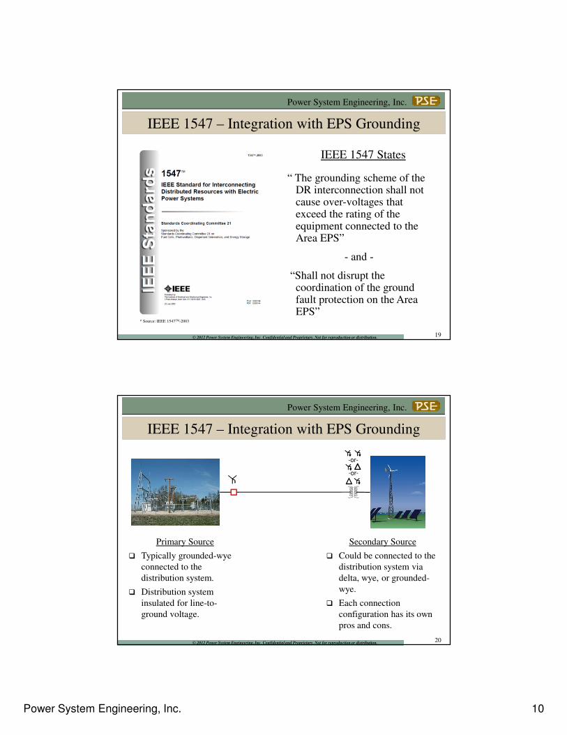
IEEE 1547 – Integration with EPS Grounding
“ The grounding scheme of the DR interconnection shall not cause over-voltages that exceed the rating of the equipment connected to the Area EPS”
- and -
“Shall not disrupt the coordination of the ground fault protection on the Area EPS”
IEEE 1547 States
* Source: IEEE 1547TM-2003
19
Power System Engineering, Inc.
© 2012 Power System Engineering, Inc. Confidential and Proprietary. Not for reproduction or distribution.
-or-
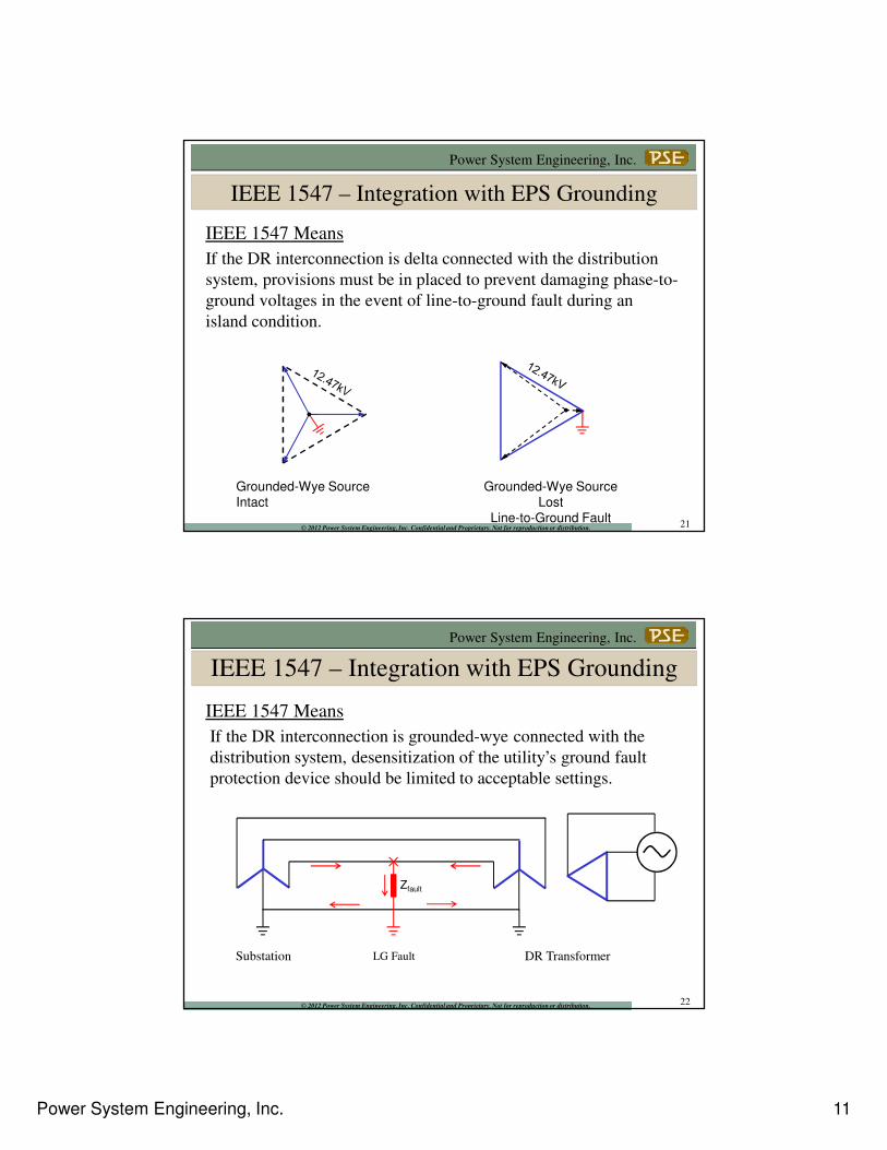
IEEE 1547 – Integration with EPS Grounding
Primary Source
� Typically grounded-wye
connected to the
distribution system.
� Distribution system
insulated for line-to-
ground voltage.
Secondary Source
� Could be connected to the
distribution system via
delta, wye, or grounded-
wye.
� Each connection
configuration has its own
pros and cons.
-or-
20
Power System Engineering, Inc. 11
Power System Engineering, Inc.
© 2012 Power System Engineering, Inc. Confidential and Proprietary. Not for reproduction or distribution.
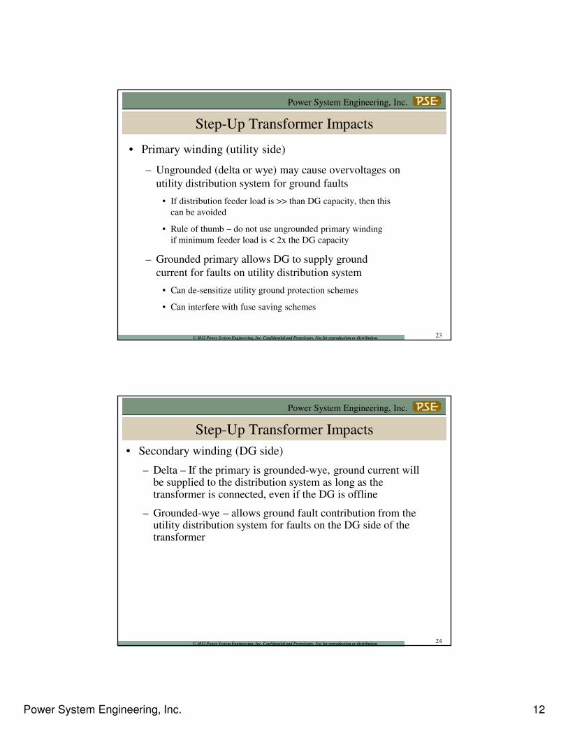
IEEE 1547 Means
If the DR interconnection is delta connected with the distribution
system, provisions must be in placed to prevent damaging phase-to-
ground voltages in the event of line-to-ground fault during an
island condition.
IEEE 1547 – Integration with EPS Grounding
Grounded-Wye Source
Intact
Grounded-Wye Source
Lost
Line-to-Ground Fault21
Power System Engineering, Inc.
© 2012 Power System Engineering, Inc. Confidential and Proprietary. Not for reproduction or distribution.
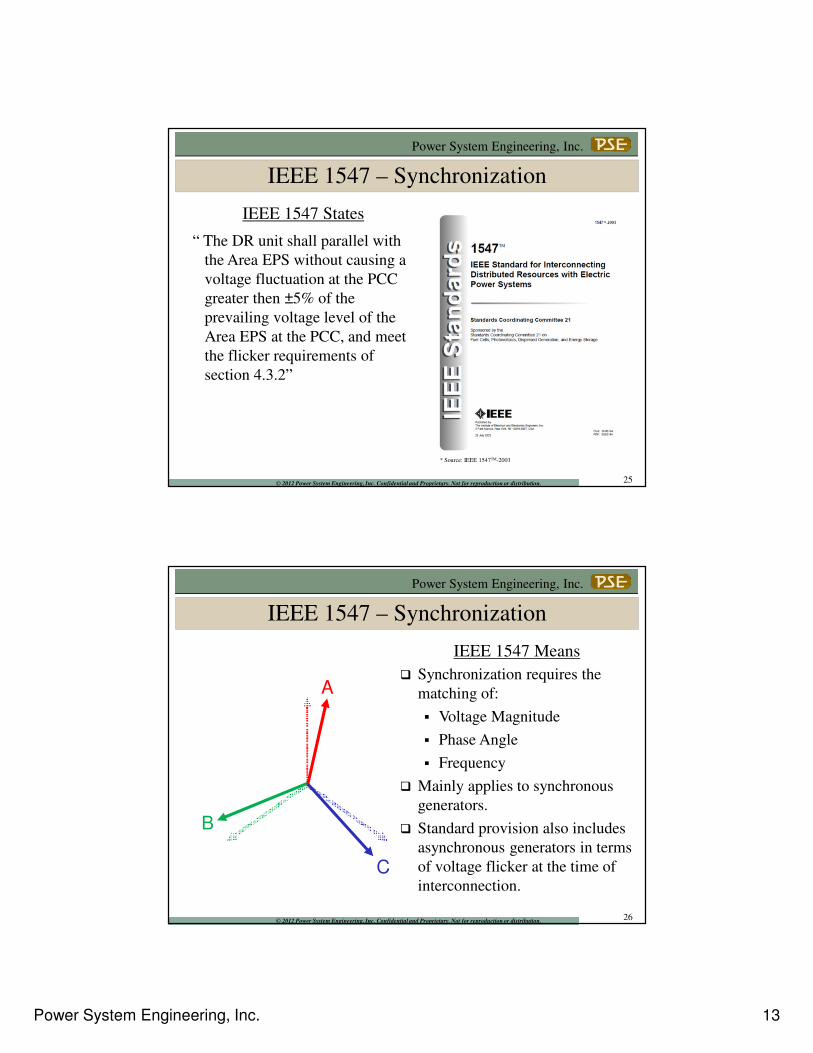
Substation DR Transformer
Zfault
LG Fault
IEEE 1547 – Integration with EPS Grounding
If the DR interconnection is grounded-wye connected with the
distribution system, desensitization of the utility’s ground fault
protection device should be limited to acceptable settings.
IEEE 1547 Means
22
Power System Engineering, Inc. 12
Power System Engineering, Inc.
© 2012 Power System Engineering, Inc. Confidential and Proprietary. Not for reproduction or distribution.
Step-Up Transformer Impacts
• Primary winding (utility side)
– Ungrounded (delta or wye) may cause overvoltages on
utility distribution system for ground faults
• If distribution feeder load is >> than DG capacity, then this
can be avoided
• Rule of thumb – do not use ungrounded primary winding
if minimum feeder load is < 2x the DG capacity
– Grounded primary allows DG to supply ground
current for faults on utility distribution system
• Can de-sensitize utility ground protection schemes
• Can interfere with fuse saving schemes
23
Power System Engineering, Inc.
© 2012 Power System Engineering, Inc. Confidential and Proprietary. Not for reproduction or distribution.
Step-Up Transformer Impacts
• Secondary winding (DG side)
– Delta – If the primary is grounded-wye, ground current will be supplied to the distribution system as long as the transformer is connected, even if the DG is offline
– Grounded-wye – allows ground fault contribution from the utility distribution system for faults on the DG side of the transformer
24
Power System Engineering, Inc. 13
Power System Engineering, Inc.
© 2012 Power System Engineering, Inc. Confidential and Proprietary. Not for reproduction or distribution.
“ The DR unit shall parallel with
the Area EPS without causing a
voltage fluctuation at the PCC
greater then ±5% of the
prevailing voltage level of the
Area EPS at the PCC, and meet
the flicker requirements of
section 4.3.2”
IEEE 1547 States
* Source: IEEE 1547TM-2003
IEEE 1547 – Synchronization
25
Power System Engineering, Inc.
© 2012 Power System Engineering, Inc. Confidential and Proprietary. Not for reproduction or distribution.
A
C
B
IEEE 1547 – Synchronization
� Synchronization requires the
matching of:
� Voltage Magnitude
� Phase Angle
� Frequency
� Mainly applies to synchronous
generators.
� Standard provision also includes
asynchronous generators in terms
of voltage flicker at the time of
interconnection.
IEEE 1547 Means
26

Power System Engineering, Inc. 14
Power System Engineering, Inc.
© 2012 Power System Engineering, Inc. Confidential and Proprietary. Not for reproduction or distribution.
IEEE 1547 Means
For synchronous and inverter-based interconnection systems that
produce a fundamental voltage before paralleling, the following
synchronization limits shall apply:
IEEE 1547 – Synchronization
* Source: IEEE 1547TM-2003
27
Power System Engineering, Inc.
© 2012 Power System Engineering, Inc. Confidential and Proprietary. Not for reproduction or distribution.
IEEE 1547 – Synchronization
IEEE 1547 MeansFor asynchronous and inverter interconnections, the maximum
start-up (in-rush) current drawing by the DR shall not cause a
voltage flicker greater than 5% on the distribution system.
* Source: IEEE Std 141-1993 “IEEE Recommended Practice for Electric Power Distribution for Industrial Plants” 28
Power System Engineering, Inc. 15
Power System Engineering, Inc.
© 2012 Power System Engineering, Inc. Confidential and Proprietary. Not for reproduction or distribution.
Inadvertent Energization of the Area EPS
“ The DR shall not energize
the Area EPS when the Area
EPS is de-energized”
IEEE 1547 States
* Source: IEEE 1547TM-2003
29
Power System Engineering, Inc.
© 2012 Power System Engineering, Inc. Confidential and Proprietary. Not for reproduction or distribution.
Inadvertent Energization of the Area EPS
IEEE 1547 Means
� When the utility distribution is de-energized, the DG unit cannot inadvertently energize the system.
� Required to ensure personnel safety during line maintenance or service restoration activities.
30
Power System Engineering, Inc. 16
Power System Engineering, Inc.
© 2012 Power System Engineering, Inc. Confidential and Proprietary. Not for reproduction or distribution.
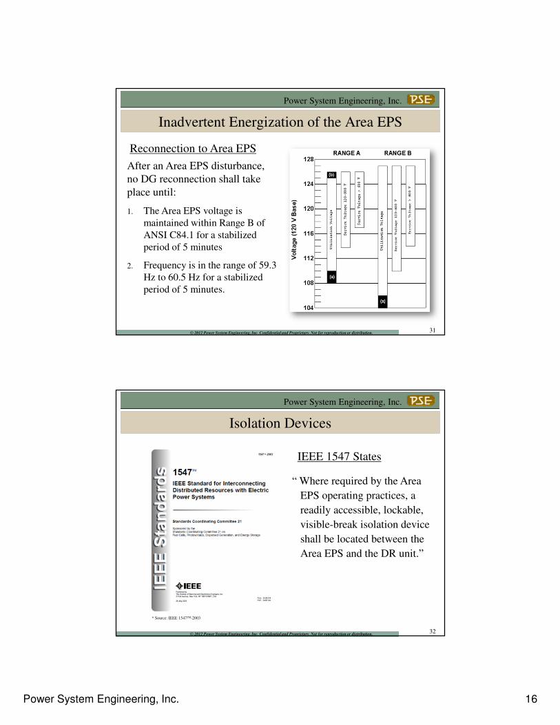
Inadvertent Energization of the Area EPS
Reconnection to Area EPS
After an Area EPS disturbance,
no DG reconnection shall take
place until:
1. The Area EPS voltage is
maintained within Range B of
ANSI C84.1 for a stabilized
period of 5 minutes
2. Frequency is in the range of 59.3
Hz to 60.5 Hz for a stabilized
period of 5 minutes.
31
Power System Engineering, Inc.
© 2012 Power System Engineering, Inc. Confidential and Proprietary. Not for reproduction or distribution.
Isolation Devices
“ Where required by the Area
EPS operating practices, a
readily accessible, lockable,
visible-break isolation device
shall be located between the
Area EPS and the DR unit.”
IEEE 1547 States
* Source: IEEE 1547TM-2003
32
Power System Engineering, Inc. 17
Power System Engineering, Inc.
© 2012 Power System Engineering, Inc. Confidential and Proprietary. Not for reproduction or distribution.
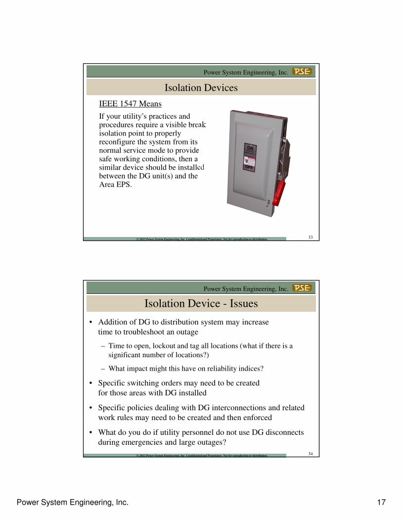
Isolation Devices
If your utility’s practices and procedures require a visible break isolation point to properly reconfigure the system from its normal service mode to provide safe working conditions, then a similar device should be installed between the DG unit(s) and the Area EPS.
IEEE 1547 Means
33
Power System Engineering, Inc.
© 2012 Power System Engineering, Inc. Confidential and Proprietary. Not for reproduction or distribution.
• Addition of DG to distribution system may increase
time to troubleshoot an outage
– Time to open, lockout and tag all locations (what if there is a
significant number of locations?)
– What impact might this have on reliability indices?
• Specific switching orders may need to be created
for those areas with DG installed
• Specific policies dealing with DG interconnections and related
work rules may need to be created and then enforced
• What do you do if utility personnel do not use DG disconnects
during emergencies and large outages?
Isolation Device - Issues
34
Power System Engineering, Inc. 18
Power System Engineering, Inc.
© 2012 Power System Engineering, Inc. Confidential and Proprietary. Not for reproduction or distribution.
Area EPS Reclosing Coordination
“The DR shall cease to
energize the Area EPS circuit
to which it is connected prior
to reclosure by the Area EPS.”
IEEE 1547 States
* Source: IEEE 1547TM-2003
35
Power System Engineering, Inc.
© 2012 Power System Engineering, Inc. Confidential and Proprietary. Not for reproduction or distribution.
Area EPS Faults
Items to be Aware of Include:
� Increase in the maximum available fault current that existing
protection devices may be exposed to due to the contribution of
DG.
� If the DG fault current contribution is substantial, the utility’s
contribution to the fault may be reduced and could affect the
time it takes the utility’s protection equipment to respond to a
fault, or in the extreme case, prevent the utility’s protection
equipment from detecting a fault.
� Proper coordination between protection devices between the DR
and fault.
36
Power System Engineering, Inc. 19
Power System Engineering, Inc.
© 2012 Power System Engineering, Inc. Confidential and Proprietary. Not for reproduction or distribution.
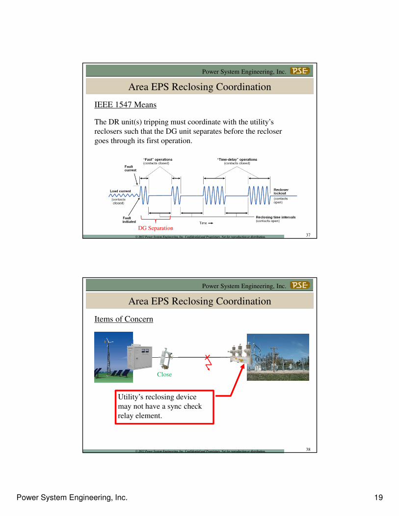
Area EPS Reclosing Coordination
The DR unit(s) tripping must coordinate with the utility’s
reclosers such that the DG unit separates before the recloser
goes through its first operation.
IEEE 1547 Means
DG Separation37
Power System Engineering, Inc.
© 2012 Power System Engineering, Inc. Confidential and Proprietary. Not for reproduction or distribution.
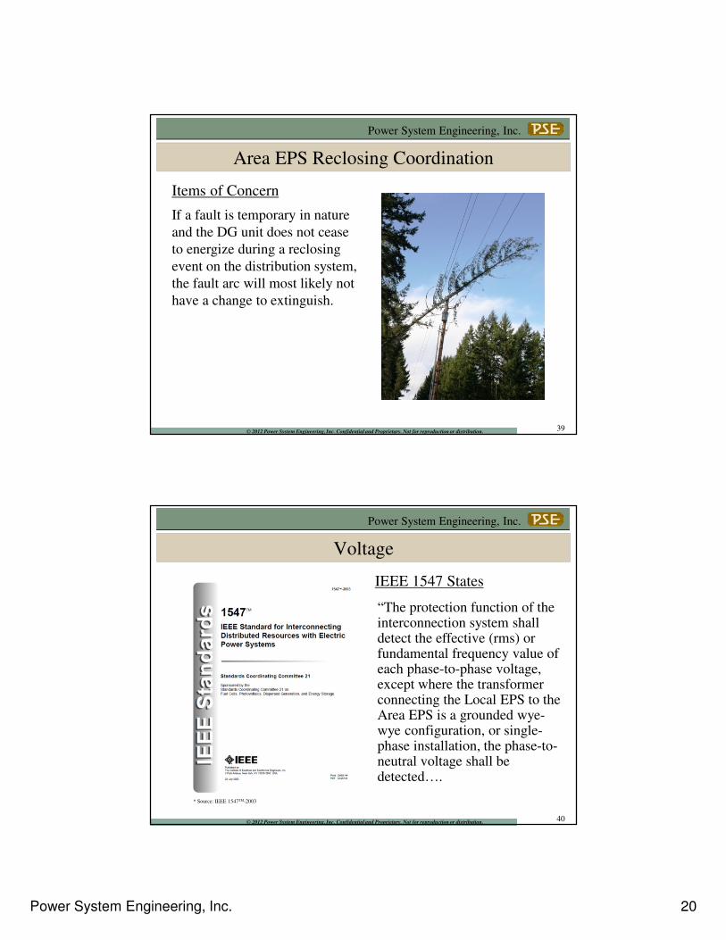
Area EPS Reclosing Coordination
Utility’s reclosing device
may not have a sync check
relay element.
Items of Concern
Close
38
Power System Engineering, Inc. 20
Power System Engineering, Inc.
© 2012 Power System Engineering, Inc. Confidential and Proprietary. Not for reproduction or distribution.
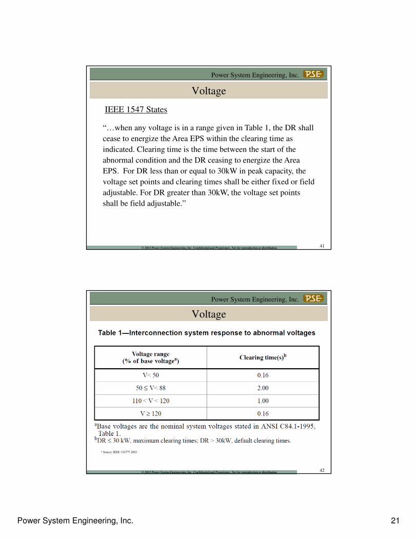
Area EPS Reclosing Coordination
If a fault is temporary in nature
and the DG unit does not cease
to energize during a reclosing
event on the distribution system,
the fault arc will most likely not
have a change to extinguish.
Items of Concern
39
Power System Engineering, Inc.
© 2012 Power System Engineering, Inc. Confidential and Proprietary. Not for reproduction or distribution.
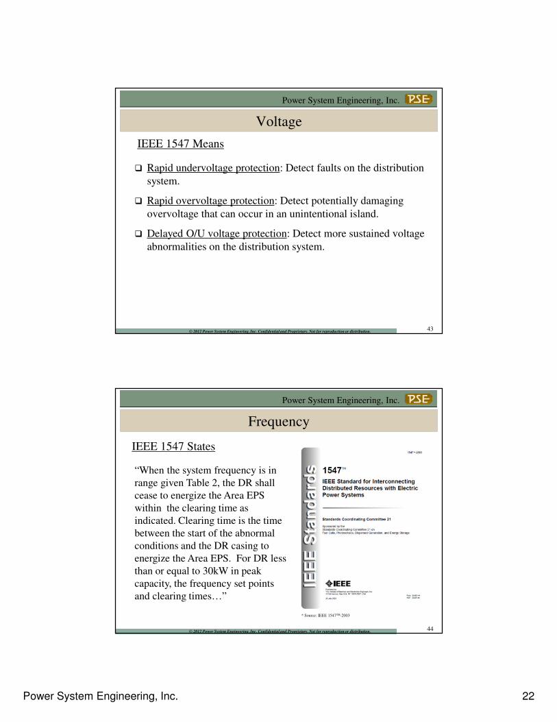
Voltage
“The protection function of the interconnection system shall detect the effective (rms) or fundamental frequency value of each phase-to-phase voltage, except where the transformer connecting the Local EPS to the Area EPS is a grounded wye-wye configuration, or single-phase installation, the phase-to-neutral voltage shall be detected….
IEEE 1547 States
* Source: IEEE 1547TM-2003
40
Power System Engineering, Inc. 21
Power System Engineering, Inc.
© 2012 Power System Engineering, Inc. Confidential and Proprietary. Not for reproduction or distribution.
Voltage
“…when any voltage is in a range given in Table 1, the DR shall
cease to energize the Area EPS within the clearing time as
indicated. Clearing time is the time between the start of the
abnormal condition and the DR ceasing to energize the Area
EPS. For DR less than or equal to 30kW in peak capacity, the
voltage set points and clearing times shall be either fixed or field
adjustable. For DR greater than 30kW, the voltage set points
shall be field adjustable.”
IEEE 1547 States
41
Power System Engineering, Inc.
© 2012 Power System Engineering, Inc. Confidential and Proprietary. Not for reproduction or distribution.
Voltage
* Source: IEEE 1547TM-2003
42
Power System Engineering, Inc. 22
Power System Engineering, Inc.
© 2012 Power System Engineering, Inc. Confidential and Proprietary. Not for reproduction or distribution.
Voltage
� Rapid undervoltage protection: Detect faults on the distribution
system.
� Rapid overvoltage protection: Detect potentially damaging
overvoltage that can occur in an unintentional island.
� Delayed O/U voltage protection: Detect more sustained voltage
abnormalities on the distribution system.
IEEE 1547 Means
43
Power System Engineering, Inc.
© 2012 Power System Engineering, Inc. Confidential and Proprietary. Not for reproduction or distribution.
Frequency
“When the system frequency is in
range given Table 2, the DR shall
cease to energize the Area EPS
within the clearing time as
indicated. Clearing time is the time
between the start of the abnormal
conditions and the DR casing to
energize the Area EPS. For DR less
than or equal to 30kW in peak
capacity, the frequency set points
and clearing times…”
IEEE 1547 States
* Source: IEEE 1547TM-2003
44
Power System Engineering, Inc. 23
Power System Engineering, Inc.
© 2012 Power System Engineering, Inc. Confidential and Proprietary. Not for reproduction or distribution.
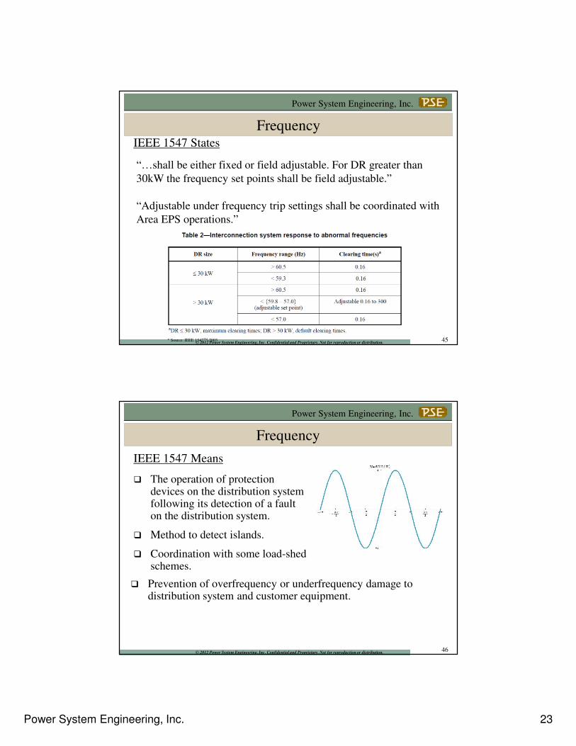
Frequency
“…shall be either fixed or field adjustable. For DR greater than
30kW the frequency set points shall be field adjustable.”
“Adjustable under frequency trip settings shall be coordinated with
Area EPS operations.”
IEEE 1547 States
* Source: IEEE 1547TM-2003 45
Power System Engineering, Inc.
© 2012 Power System Engineering, Inc. Confidential and Proprietary. Not for reproduction or distribution.
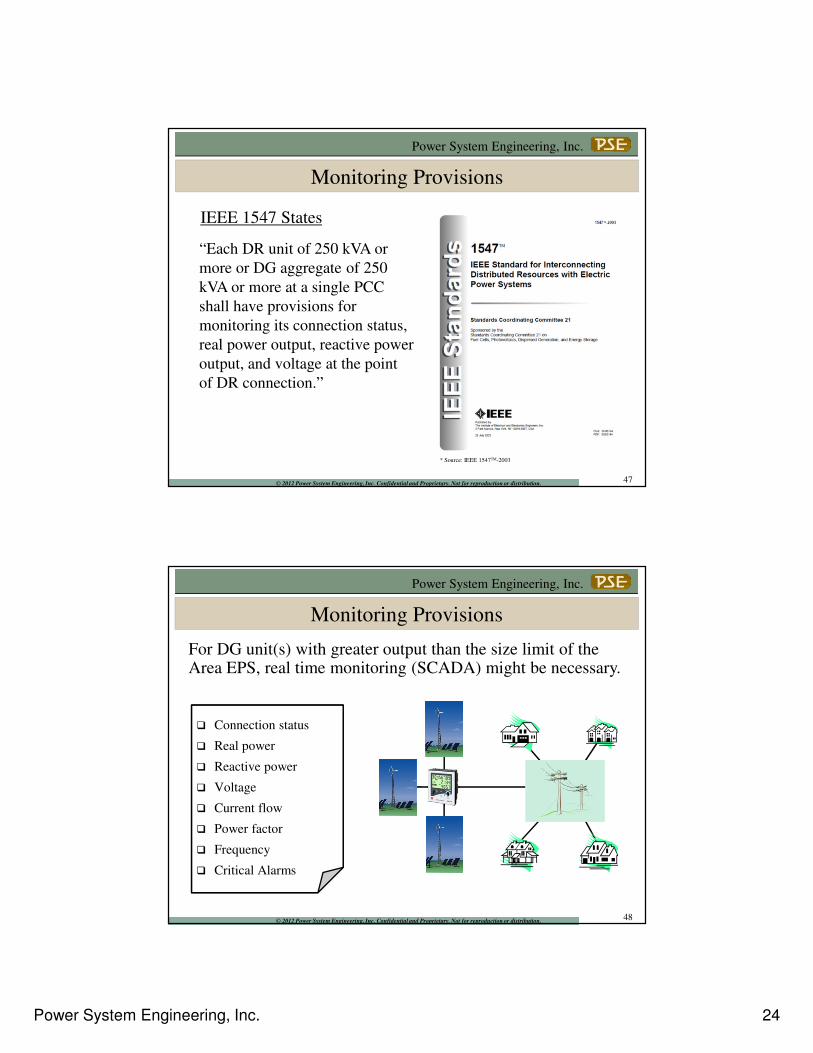
Frequency
� The operation of protection devices on the distribution system following its detection of a fault on the distribution system.
� Method to detect islands.
� Coordination with some load-shed schemes.
� Prevention of overfrequency or underfrequency damage to distribution system and customer equipment.
IEEE 1547 Means
46
Power System Engineering, Inc. 24
Power System Engineering, Inc.
© 2012 Power System Engineering, Inc. Confidential and Proprietary. Not for reproduction or distribution.
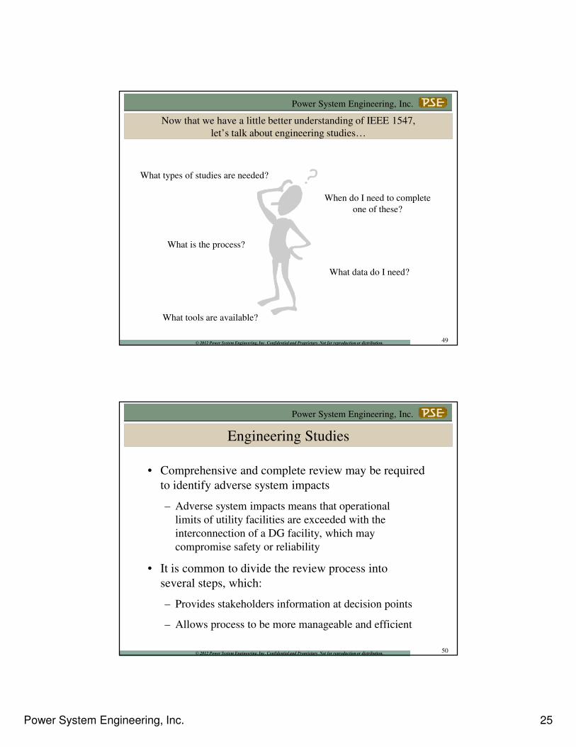
Monitoring Provisions
“Each DR unit of 250 kVA or
more or DG aggregate of 250
kVA or more at a single PCC
shall have provisions for
monitoring its connection status,
real power output, reactive power
output, and voltage at the point
of DR connection.”
IEEE 1547 States
* Source: IEEE 1547TM-2003
47
Power System Engineering, Inc.
© 2012 Power System Engineering, Inc. Confidential and Proprietary. Not for reproduction or distribution.
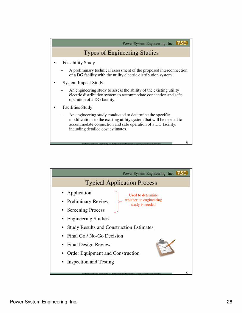
Monitoring Provisions
For DG unit(s) with greater output than the size limit of the Area EPS, real time monitoring (SCADA) might be necessary.
� Connection status
� Real power
� Reactive power
� Voltage
� Current flow
� Power factor
� Frequency
� Critical Alarms
48
Power System Engineering, Inc. 25
Power System Engineering, Inc.
© 2012 Power System Engineering, Inc. Confidential and Proprietary. Not for reproduction or distribution.
Now that we have a little better understanding of IEEE 1547,
let’s talk about engineering studies…
What types of studies are needed?
When do I need to complete
one of these?
What is the process?
What data do I need?
What tools are available?
49
Power System Engineering, Inc.
© 2012 Power System Engineering, Inc. Confidential and Proprietary. Not for reproduction or distribution.
Engineering Studies
• Comprehensive and complete review may be required
to identify adverse system impacts
– Adverse system impacts means that operational
limits of utility facilities are exceeded with the
interconnection of a DG facility, which may
compromise safety or reliability
• It is common to divide the review process into
several steps, which:
– Provides stakeholders information at decision points
– Allows process to be more manageable and efficient
50
Power System Engineering, Inc. 26
Power System Engineering, Inc.
© 2012 Power System Engineering, Inc. Confidential and Proprietary. Not for reproduction or distribution.
Types of Engineering Studies
• Feasibility Study
– A preliminary technical assessment of the proposed interconnection of a DG facility with the utility electric distribution system.
• System Impact Study
– An engineering study to assess the ability of the existing utility electric distribution system to accommodate connection and safe operation of a DG facility.
• Facilities Study
– An engineering study conducted to determine the specific modifications to the existing utility system that will be needed to accommodate connection and safe operation of a DG facility, including detailed cost estimates.
51
Power System Engineering, Inc.
© 2012 Power System Engineering, Inc. Confidential and Proprietary. Not for reproduction or distribution.
• Application
• Preliminary Review
• Screening Process
• Engineering Studies
• Study Results and Construction Estimates
• Final Go / No-Go Decision
• Final Design Review
• Order Equipment and Construction
• Inspection and Testing
Used to determine
whether an engineering
study is needed
Typical Application Process
52
Power System Engineering, Inc. 27
Power System Engineering, Inc.
© 2012 Power System Engineering, Inc. Confidential and Proprietary. Not for reproduction or distribution.
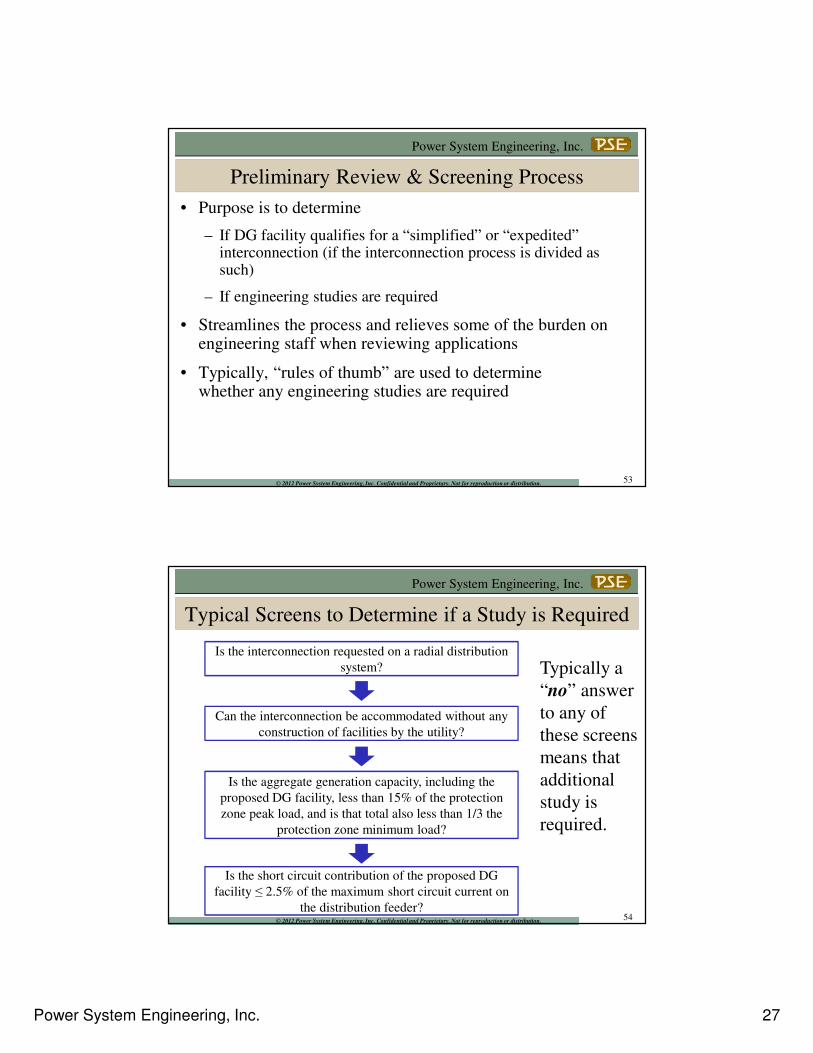
Preliminary Review & Screening Process
• Purpose is to determine
– If DG facility qualifies for a “simplified” or “expedited” interconnection (if the interconnection process is divided as such)
– If engineering studies are required
• Streamlines the process and relieves some of the burden on engineering staff when reviewing applications
• Typically, “rules of thumb” are used to determine whether any engineering studies are required
53
Power System Engineering, Inc.
© 2012 Power System Engineering, Inc. Confidential and Proprietary. Not for reproduction or distribution.
Is the interconnection requested on a radial distribution
system?
Can the interconnection be accommodated without any
construction of facilities by the utility?
Is the aggregate generation capacity, including the
proposed DG facility, less than 15% of the protection
zone peak load, and is that total also less than 1/3 the
protection zone minimum load?
Is the short circuit contribution of the proposed DG
facility ≤ 2.5% of the maximum short circuit current on
the distribution feeder?
Typically a
“no” answer
to any of
these screens
means that
additional
study is
required.
Typical Screens to Determine if a Study is Required
54
Power System Engineering, Inc. 28
Power System Engineering, Inc.
© 2012 Power System Engineering, Inc. Confidential and Proprietary. Not for reproduction or distribution.
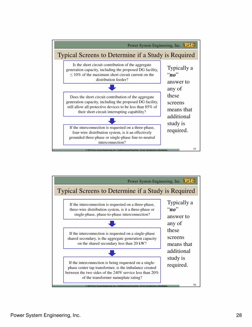
Is the short circuit contribution of the aggregate
generation capacity, including the proposed DG facility,
≤ 10% of the maximum short circuit current on the
distribution feeder?
Does the short circuit contribution of the aggregate
generation capacity, including the proposed DG facility,
still allow all protective devices to be less than 85% of
their short circuit interrupting capability?
If the interconnection is requested on a three-phase,
four-wire distribution system, is it an effectively
grounded three-phase or single-phase line-to-neutral
interconnection?
Typically a
“no”
answer to
any of
these
screens
means that
additional
study is
required.
Typical Screens to Determine if a Study is Required
55
Power System Engineering, Inc.
© 2012 Power System Engineering, Inc. Confidential and Proprietary. Not for reproduction or distribution.
Typical Screens to Determine if a Study is Required
If the interconnection is requested on a three-phase,
three-wire distribution system, is it a three-phase or
single-phase, phase-to-phase interconnection?
If the interconnection is requested on a single-phase
shared secondary, is the aggregate generation capacity
on the shared secondary less than 20 kW?
If the interconnection is being requested on a single-
phase center tap transformer, is the imbalance created
between the two sides of the 240V service less than 20%
of the transformer nameplate rating?
Typically a
“no”
answer to
any of
these
screens
means that
additional
study is
required.
56
Power System Engineering, Inc. 29
Power System Engineering, Inc.
© 2012 Power System Engineering, Inc. Confidential and Proprietary. Not for reproduction or distribution.
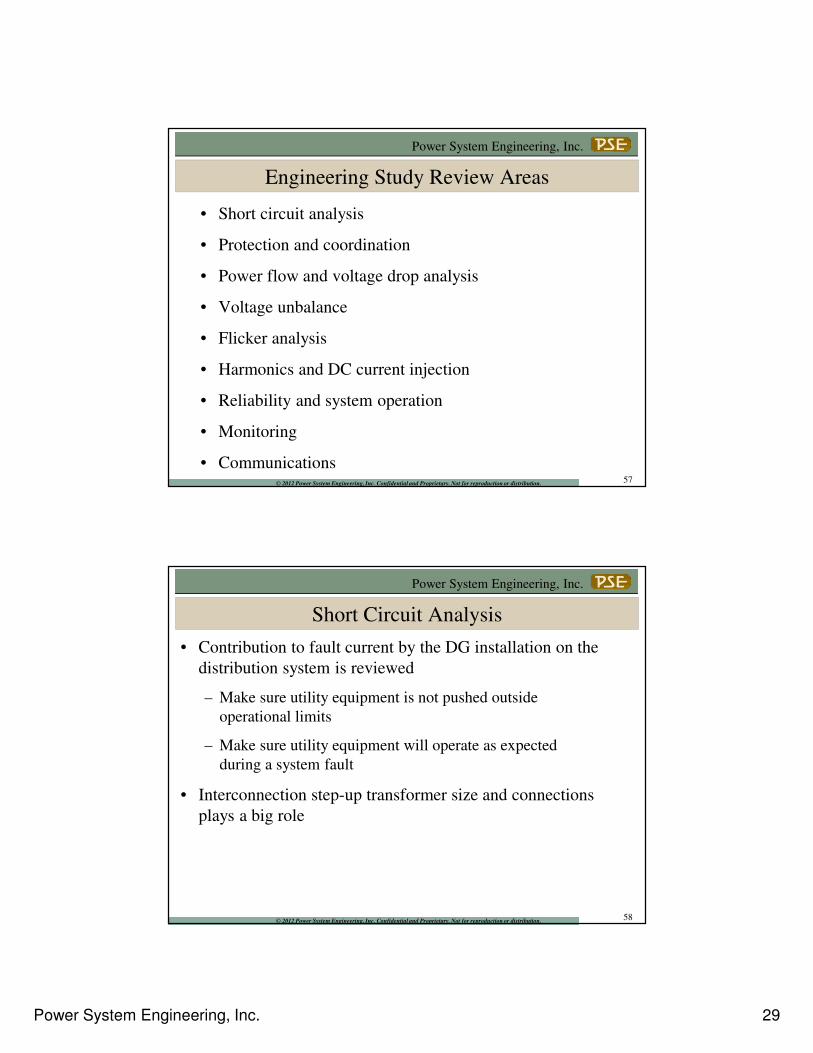
Engineering Study Review Areas
• Short circuit analysis
• Protection and coordination
• Power flow and voltage drop analysis
• Voltage unbalance
• Flicker analysis
• Harmonics and DC current injection
• Reliability and system operation
• Monitoring
• Communications57
Power System Engineering, Inc.
© 2012 Power System Engineering, Inc. Confidential and Proprietary. Not for reproduction or distribution.
Short Circuit Analysis
• Contribution to fault current by the DG installation on the
distribution system is reviewed
– Make sure utility equipment is not pushed outside
operational limits
– Make sure utility equipment will operate as expected
during a system fault
• Interconnection step-up transformer size and connections
plays a big role
58
Power System Engineering, Inc. 30
Power System Engineering, Inc.
© 2012 Power System Engineering, Inc. Confidential and Proprietary. Not for reproduction or distribution.
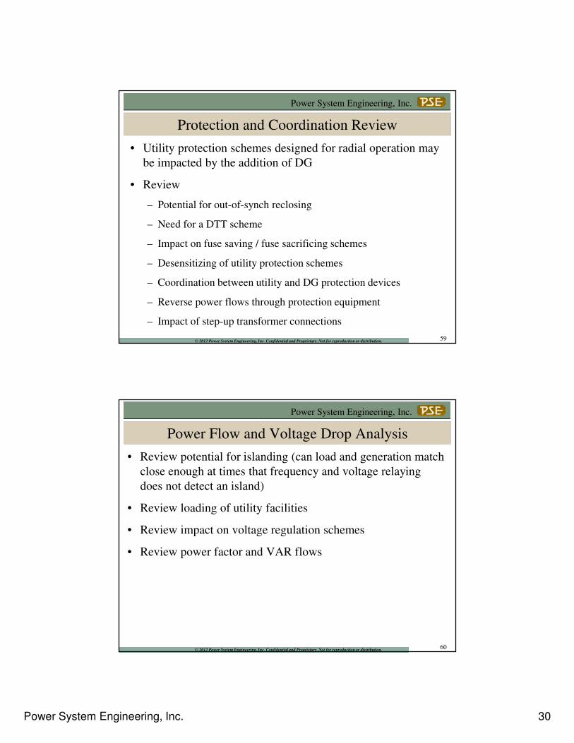
Protection and Coordination Review
• Utility protection schemes designed for radial operation may
be impacted by the addition of DG
• Review
– Potential for out-of-synch reclosing
– Need for a DTT scheme
– Impact on fuse saving / fuse sacrificing schemes
– Desensitizing of utility protection schemes
– Coordination between utility and DG protection devices
– Reverse power flows through protection equipment
– Impact of step-up transformer connections
59
Power System Engineering, Inc.
© 2012 Power System Engineering, Inc. Confidential and Proprietary. Not for reproduction or distribution.
Power Flow and Voltage Drop Analysis
• Review potential for islanding (can load and generation match
close enough at times that frequency and voltage relaying
does not detect an island)
• Review loading of utility facilities
• Review impact on voltage regulation schemes
• Review power factor and VAR flows
60
Power System Engineering, Inc. 31
Power System Engineering, Inc.
© 2012 Power System Engineering, Inc. Confidential and Proprietary. Not for reproduction or distribution.
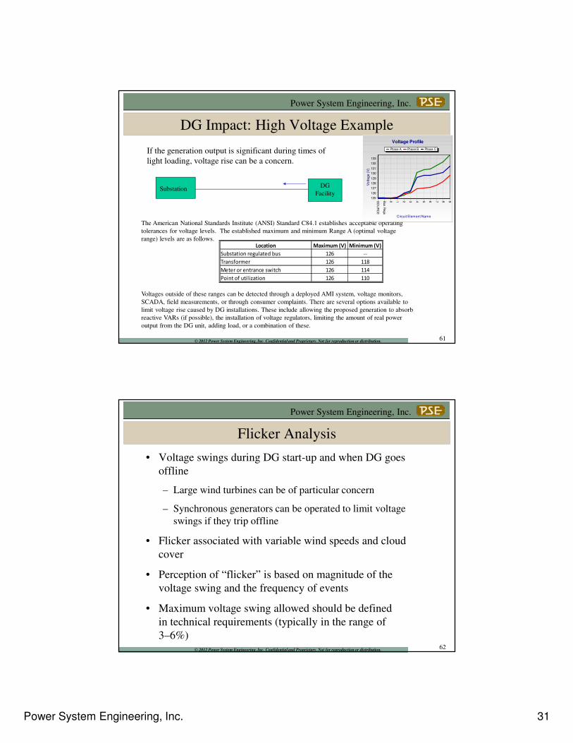
DG Impact: High Voltage Example
SubstationDG
Facility
If the generation output is significant during times of
light loading, voltage rise can be a concern.
The American National Standards Institute (ANSI) Standard C84.1 establishes acceptable operating
tolerances for voltage levels. The established maximum and minimum Range A (optimal voltage
range) levels are as follows.
Voltages outside of these ranges can be detected through a deployed AMI system, voltage monitors,
SCADA, field measurements, or through consumer complaints. There are several options available to
limit voltage rise caused by DG installations. These include allowing the proposed generation to absorb
reactive VARs (if possible), the installation of voltage regulators, limiting the amount of real power
output from the DG unit, adding load, or a combination of these.
Location Maximum (V) Minimum (V)
Substation regulated bus 126 --
Transformer 126 118
Meter or entrance switch 126 114
Point of utilization 126 110
Voltage Profile
Phase A Phase B Phase C
Circuit Element Name
SO
UR
CE
Bus R
egs
0 1 2 3 4 5 6 7 8 9
Vo
lta
ge
(V
)
133
132
131
130
129
128
127
126
125
61
Power System Engineering, Inc.
© 2012 Power System Engineering, Inc. Confidential and Proprietary. Not for reproduction or distribution.
Flicker Analysis
• Voltage swings during DG start-up and when DG goes
offline
– Large wind turbines can be of particular concern
– Synchronous generators can be operated to limit voltage
swings if they trip offline
• Flicker associated with variable wind speeds and cloud
cover
• Perception of “flicker” is based on magnitude of the
voltage swing and the frequency of events
• Maximum voltage swing allowed should be defined
in technical requirements (typically in the range of
3–6%)62
Power System Engineering, Inc. 32
Power System Engineering, Inc.
© 2012 Power System Engineering, Inc. Confidential and Proprietary. Not for reproduction or distribution.
Reliability and System Operation
• Is reliability of the distribution system impacted
with the addition of the DG system?
• Are special operating procedures required?
• Reclosing and out-of-synch operation issues?
• Are limitations on the operation of the DG required?
• Are there any operational VAR requirements?
63
Power System Engineering, Inc.
© 2012 Power System Engineering, Inc. Confidential and Proprietary. Not for reproduction or distribution.
LFGTE Case Study
• Landfill gas generator interconnecting to 12.47/7.2 kV
distribution feeder
• Caterpillar 820 kW /1,025 kVA methane-fueled synchronous
generator with output at 480V
• Generator protection = Basler relays
• Intertie protection = SEL-351S relay
64
Power System Engineering, Inc. 33
Power System Engineering, Inc.
© 2012 Power System Engineering, Inc. Confidential and Proprietary. Not for reproduction or distribution.
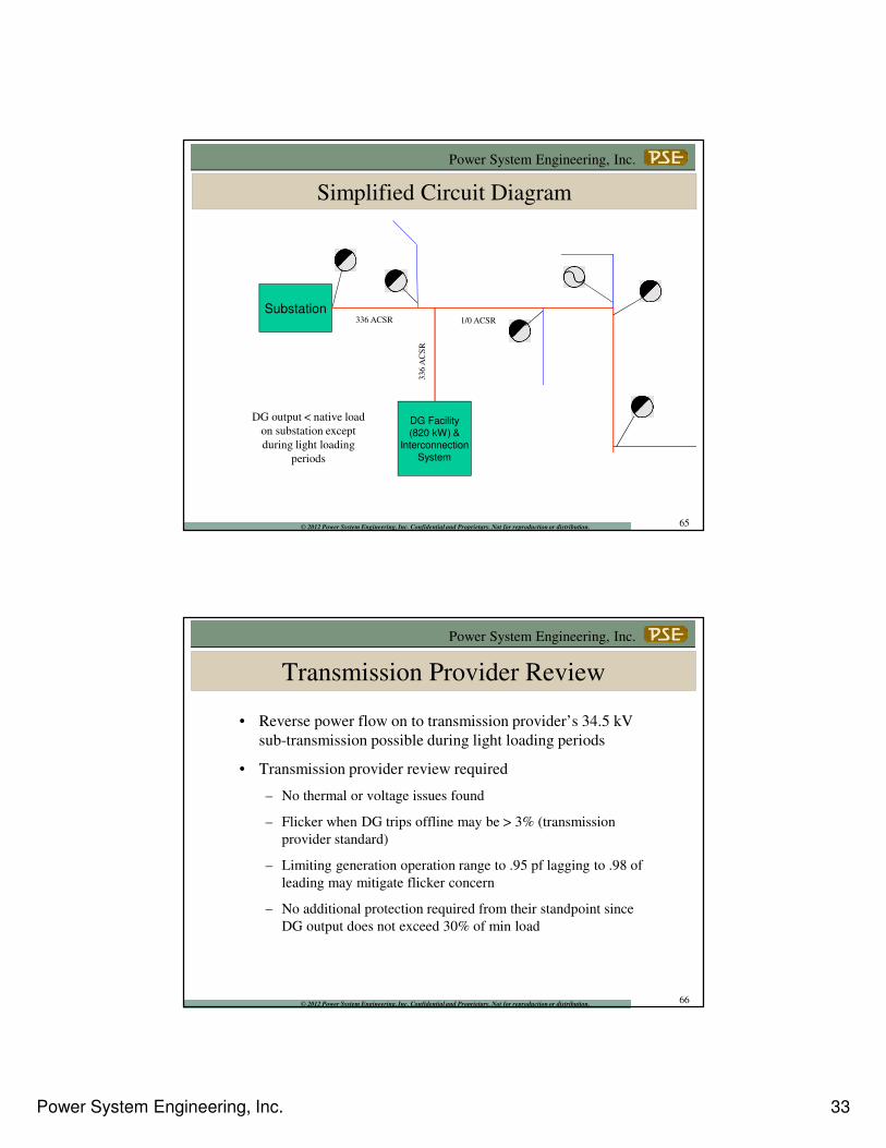
Simplified Circuit Diagram
Substation
DG Facility
(820 kW) &
Interconnection
System
336 ACSR
336 A
CS
RDG output < native load
on substation except
during light loading
periods
1/0 ACSR
65
Power System Engineering, Inc.
© 2012 Power System Engineering, Inc. Confidential and Proprietary. Not for reproduction or distribution.
Transmission Provider Review
• Reverse power flow on to transmission provider’s 34.5 kV
sub-transmission possible during light loading periods
• Transmission provider review required
– No thermal or voltage issues found
– Flicker when DG trips offline may be > 3% (transmission
provider standard)
– Limiting generation operation range to .95 pf lagging to .98 of
leading may mitigate flicker concern
– No additional protection required from their standpoint since
DG output does not exceed 30% of min load
66
Power System Engineering, Inc. 34
Power System Engineering, Inc.
© 2012 Power System Engineering, Inc. Confidential and Proprietary. Not for reproduction or distribution.
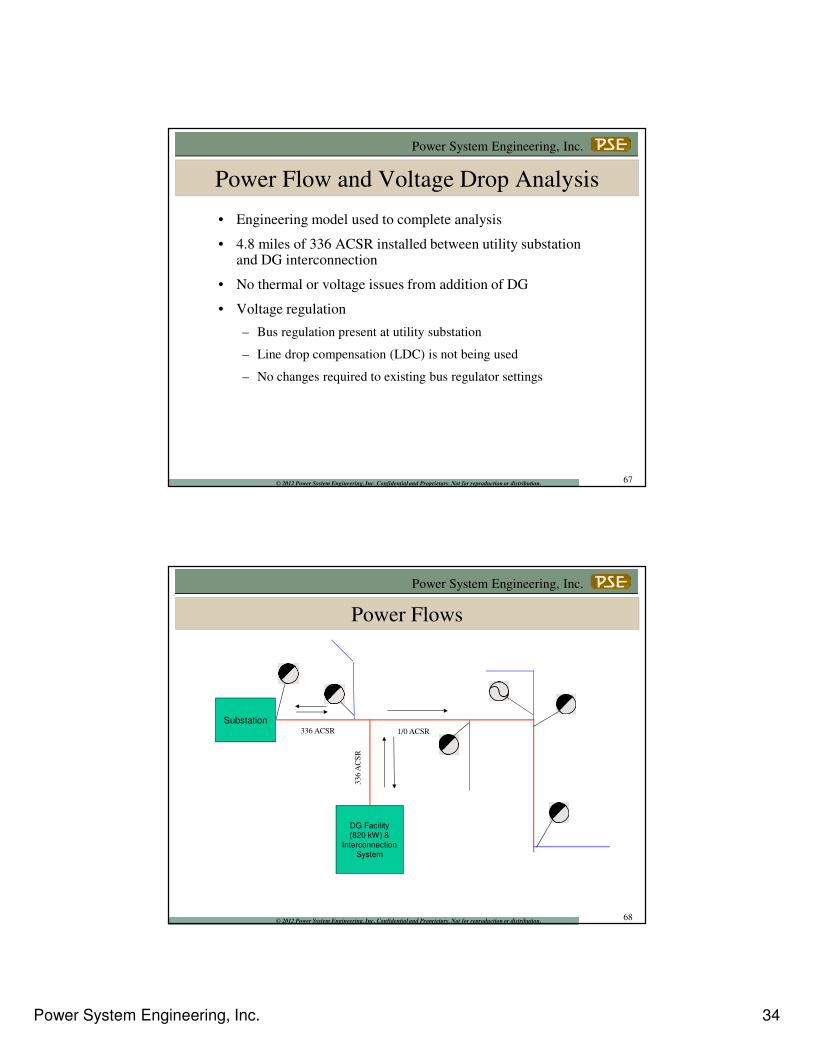
Power Flow and Voltage Drop Analysis
• Engineering model used to complete analysis
• 4.8 miles of 336 ACSR installed between utility substation and DG interconnection
• No thermal or voltage issues from addition of DG
• Voltage regulation
– Bus regulation present at utility substation
– Line drop compensation (LDC) is not being used
– No changes required to existing bus regulator settings
67
Power System Engineering, Inc.
© 2012 Power System Engineering, Inc. Confidential and Proprietary. Not for reproduction or distribution.
Power Flows
Substation
DG Facility
(820 kW) &
Interconnection
System
336 ACSR
336 A
CS
R
1/0 ACSR
68
Power System Engineering, Inc. 35
Power System Engineering, Inc.
© 2012 Power System Engineering, Inc. Confidential and Proprietary. Not for reproduction or distribution.
Transient Analysis
• Following transmission provider recommendation to limit the
operating range of the generator will mitigate flicker
concerns on the utility distribution system as well
• The intended use of the DG facility is for constant operation
• Expected frequency of flicker events is limited
• A larger voltage dip may be tolerated if it does not occur
very frequently
69
Power System Engineering, Inc.
© 2012 Power System Engineering, Inc. Confidential and Proprietary. Not for reproduction or distribution.
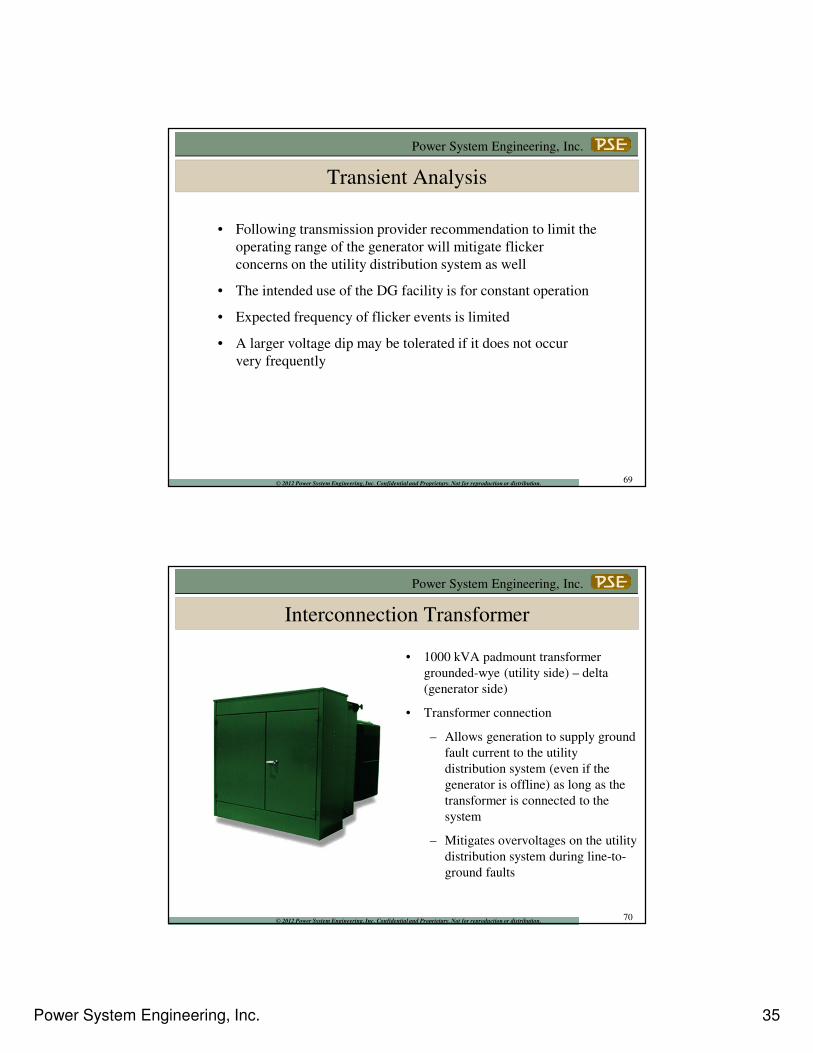
Interconnection Transformer
• 1000 kVA padmount transformer
grounded-wye (utility side) – delta
(generator side)
• Transformer connection
– Allows generation to supply ground
fault current to the utility
distribution system (even if the
generator is offline) as long as the
transformer is connected to the
system
– Mitigates overvoltages on the utility
distribution system during line-to-
ground faults
70
Power System Engineering, Inc. 36
Power System Engineering, Inc.
© 2012 Power System Engineering, Inc. Confidential and Proprietary. Not for reproduction or distribution.
Interconnection Protection
Proposed DG relaying consistent with utility technical requirements
– Utility grade relays
– Overcurrent relaying (50/51, 50/51G, 50/51N)
– Voltage controlled overcurrent relaying (51V)
– Over-voltage relay (59) / Under-voltage relay (27)
– Over/Under Frequency relays (81O/U)
– Synchronism check relay (25)
– Lockout relay (86)
71
Power System Engineering, Inc.
© 2012 Power System Engineering, Inc. Confidential and Proprietary. Not for reproduction or distribution.
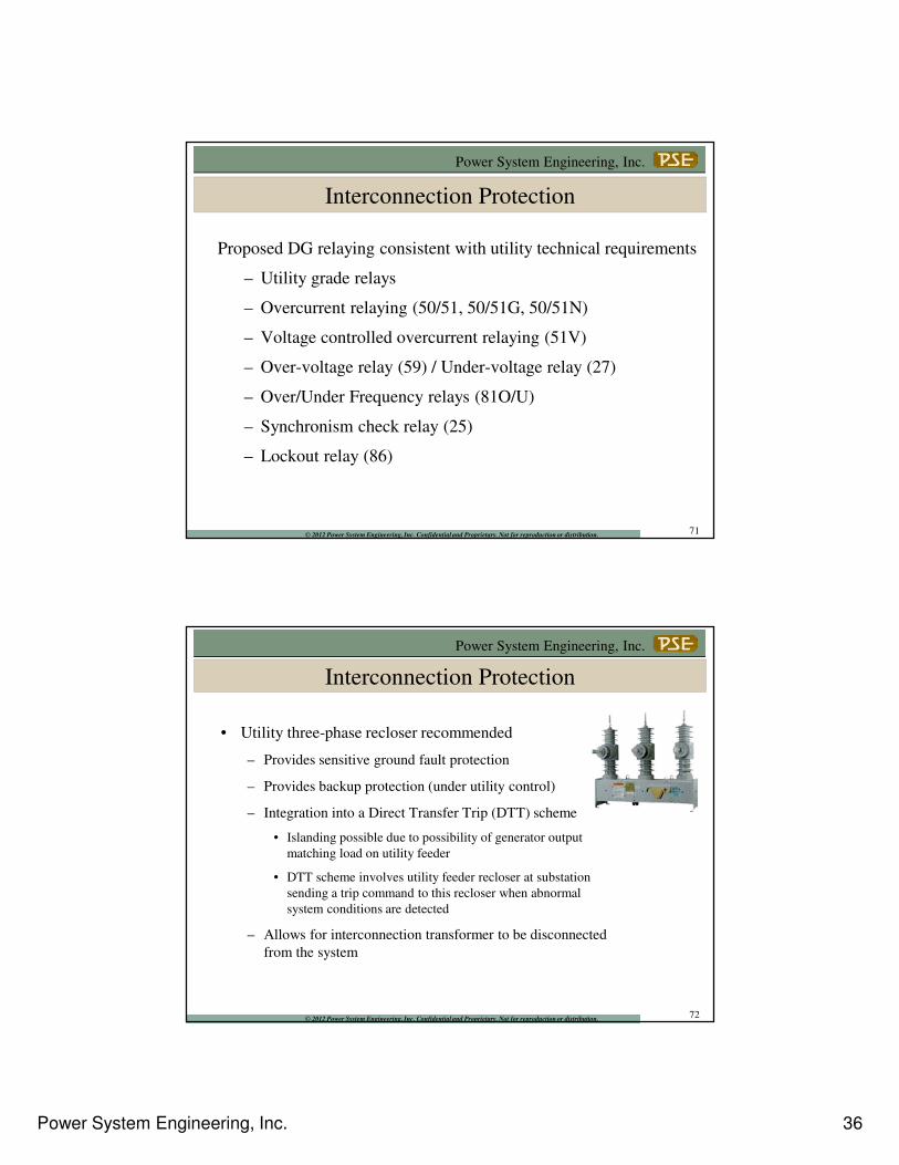
Interconnection Protection
• Utility three-phase recloser recommended
– Provides sensitive ground fault protection
– Provides backup protection (under utility control)
– Integration into a Direct Transfer Trip (DTT) scheme
• Islanding possible due to possibility of generator output
matching load on utility feeder
• DTT scheme involves utility feeder recloser at substation
sending a trip command to this recloser when abnormal
system conditions are detected
– Allows for interconnection transformer to be disconnected
from the system
72
Power System Engineering, Inc. 37
Power System Engineering, Inc.
© 2012 Power System Engineering, Inc. Confidential and Proprietary. Not for reproduction or distribution.
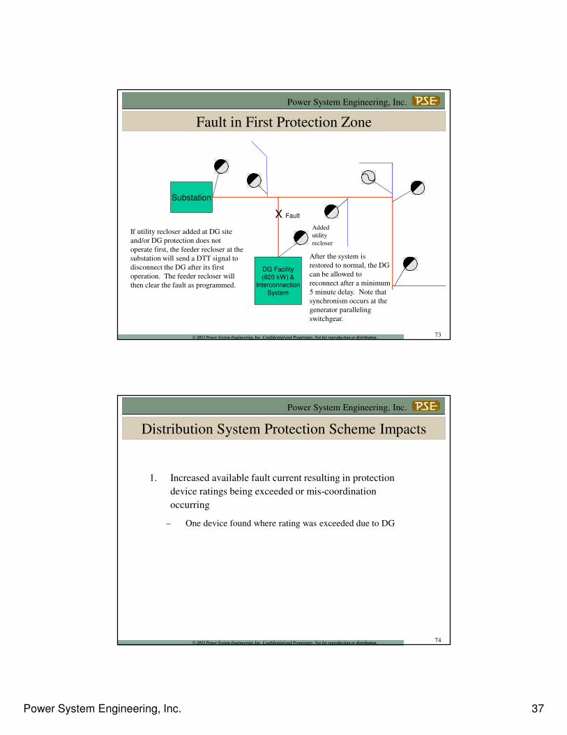
Fault in First Protection Zone
Substation
DG Facility
(820 kW) &
Interconnection
System
X Fault
Added
utility
recloser
If utility recloser added at DG site
and/or DG protection does not
operate first, the feeder recloser at the
substation will send a DTT signal to
disconnect the DG after its first
operation. The feeder recloser will
then clear the fault as programmed.
After the system is
restored to normal, the DG
can be allowed to
reconnect after a minimum
5 minute delay. Note that
synchronism occurs at the
generator paralleling
switchgear.
73
Power System Engineering, Inc.
© 2012 Power System Engineering, Inc. Confidential and Proprietary. Not for reproduction or distribution.
Distribution System Protection Scheme Impacts
1. Increased available fault current resulting in protection
device ratings being exceeded or mis-coordination
occurring
– One device found where rating was exceeded due to DG
74
Power System Engineering, Inc. 38
Power System Engineering, Inc.
© 2012 Power System Engineering, Inc. Confidential and Proprietary. Not for reproduction or distribution.
Distribution System Protection Scheme Impacts
2. Reduced ground and phase overcurrent protection sensitivity
– Feeder recloser at substation ground pickup required to be lowered
75
Power System Engineering, Inc.
© 2012 Power System Engineering, Inc. Confidential and Proprietary. Not for reproduction or distribution.
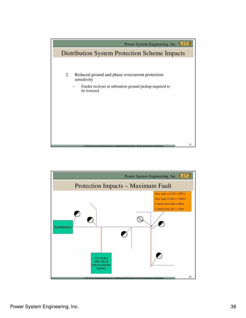
Protection Impacts – Maximum Fault
Substation
DG Facility
(820 kW) &
Interconnection
System
Max fault w/o DG = 885A
Max fault w/ DG = 1,000A
Contrib from Sub = 860A
Contrib from DG = 140A
76
Power System Engineering, Inc. 39
Power System Engineering, Inc.
© 2012 Power System Engineering, Inc. Confidential and Proprietary. Not for reproduction or distribution.
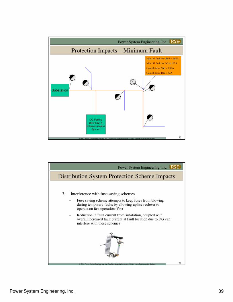
Protection Impacts – Minimum Fault
Substation
DG Facility
(820 kW) &
Interconnection
System
Min LG fault w/o DG = 165A
Min LG fault w/ DG = 167A
Contrib from Sub = 135A
Contrib from DG = 32A
77
Power System Engineering, Inc.
© 2012 Power System Engineering, Inc. Confidential and Proprietary. Not for reproduction or distribution.
Distribution System Protection Scheme Impacts
3. Interference with fuse saving schemes
– Fuse saving scheme attempts to keep fuses from blowing during temporary faults by allowing upline recloser to operate on fast operations first
– Reduction in fault current from substation, coupled with overall increased fault current at fault location due to DG can interfere with these schemes
78
Power System Engineering, Inc. 40
Power System Engineering, Inc.
© 2012 Power System Engineering, Inc. Confidential and Proprietary. Not for reproduction or distribution.
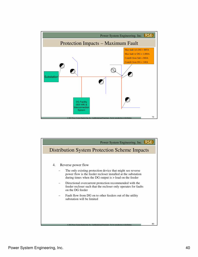
Protection Impacts – Maximum Fault
Substation
DG Facility
(820 kW) &
Interconnection
System
Max fault w/o DG = 885A
Max fault w/ DG = 1,000A
Contrib from Sub = 860A
Contrib from DG = 140A
79
Power System Engineering, Inc.
© 2012 Power System Engineering, Inc. Confidential and Proprietary. Not for reproduction or distribution.
Distribution System Protection Scheme Impacts
4. Reverse power flow
– The only existing protection device that might see reverse power flow is the feeder recloser installed at the substation during times when the DG output is > load on the feeder
– Directional overcurrent protection recommended with the feeder recloser such that the recloser only operates for faults on the DG feeder
– Fault flow from DG on to other feeders out of the utility substation will be limited
80
Power System Engineering, Inc. 41
Power System Engineering, Inc.
© 2012 Power System Engineering, Inc. Confidential and Proprietary. Not for reproduction or distribution.
Distribution System Protection Scheme Impacts
5. Out-of-synch reclosing
– The possibility of out-of-synch reclosing exists with the
feeder recloser installed at the substation
– A PT is installed on the load side of this recloser and the
existing SEL-351R relay is programmed to block reclosing if
voltage is present
81
Power System Engineering, Inc.
© 2012 Power System Engineering, Inc. Confidential and Proprietary. Not for reproduction or distribution. 82
Once it has been determined what
is required to safely interconnect
a specific DG facility to your
system, then what?
Power System Engineering, Inc. 42
Power System Engineering, Inc.
© 2012 Power System Engineering, Inc. Confidential and Proprietary. Not for reproduction or distribution. 83
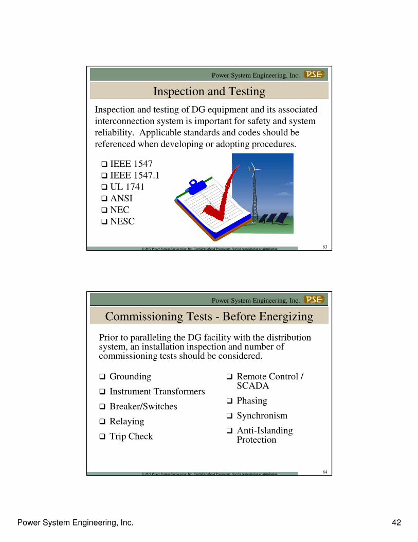
Inspection and Testing
� IEEE 1547
� IEEE 1547.1
� UL 1741
� ANSI
� NEC
� NESC
Inspection and testing of DG equipment and its associated
interconnection system is important for safety and system
reliability. Applicable standards and codes should be
referenced when developing or adopting procedures.
Power System Engineering, Inc.
© 2012 Power System Engineering, Inc. Confidential and Proprietary. Not for reproduction or distribution. 84
Commissioning Tests - Before Energizing
Prior to paralleling the DG facility with the distribution system, an installation inspection and number of commissioning tests should be considered.
� Grounding
� Instrument Transformers
� Breaker/Switches
� Relaying
� Trip Check
� Remote Control / SCADA
� Phasing
� Synchronism
� Anti-Islanding Protection
Power System Engineering, Inc. 43
Power System Engineering, Inc.
© 2012 Power System Engineering, Inc. Confidential and Proprietary. Not for reproduction or distribution.
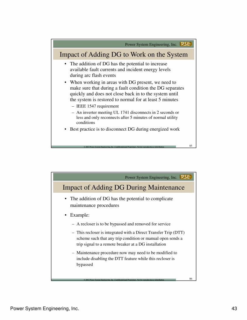
• The addition of DG has the potential to increase
available fault currents and incident energy levels
during arc flash events
• When working in areas with DG present, we need to
make sure that during a fault condition the DG separates
quickly and does not close back in to the system until
the system is restored to normal for at least 5 minutes
– IEEE 1547 requirement
– An inverter meeting UL 1741 disconnects in 2 seconds or less and only reconnects after 5 minutes of normal utility
conditions
• Best practice is to disconnect DG during energized work
Impact of Adding DG to Work on the System
85
Power System Engineering, Inc.
© 2012 Power System Engineering, Inc. Confidential and Proprietary. Not for reproduction or distribution.
• The addition of DG has the potential to complicate
maintenance procedures
• Example:
– A recloser is to be bypassed and removed for service
– This recloser is integrated with a Direct Transfer Trip (DTT)
scheme such that any trip condition or manual open sends a
trip signal to a remote breaker at a DG installation
– Maintenance procedure now may need to be modified to
include disabling the DTT feature while this recloser is
bypassed
Impact of Adding DG During Maintenance
86
Power System Engineering, Inc. 44
Power System Engineering, Inc.
© 2012 Power System Engineering, Inc. Confidential and Proprietary. Not for reproduction or distribution.
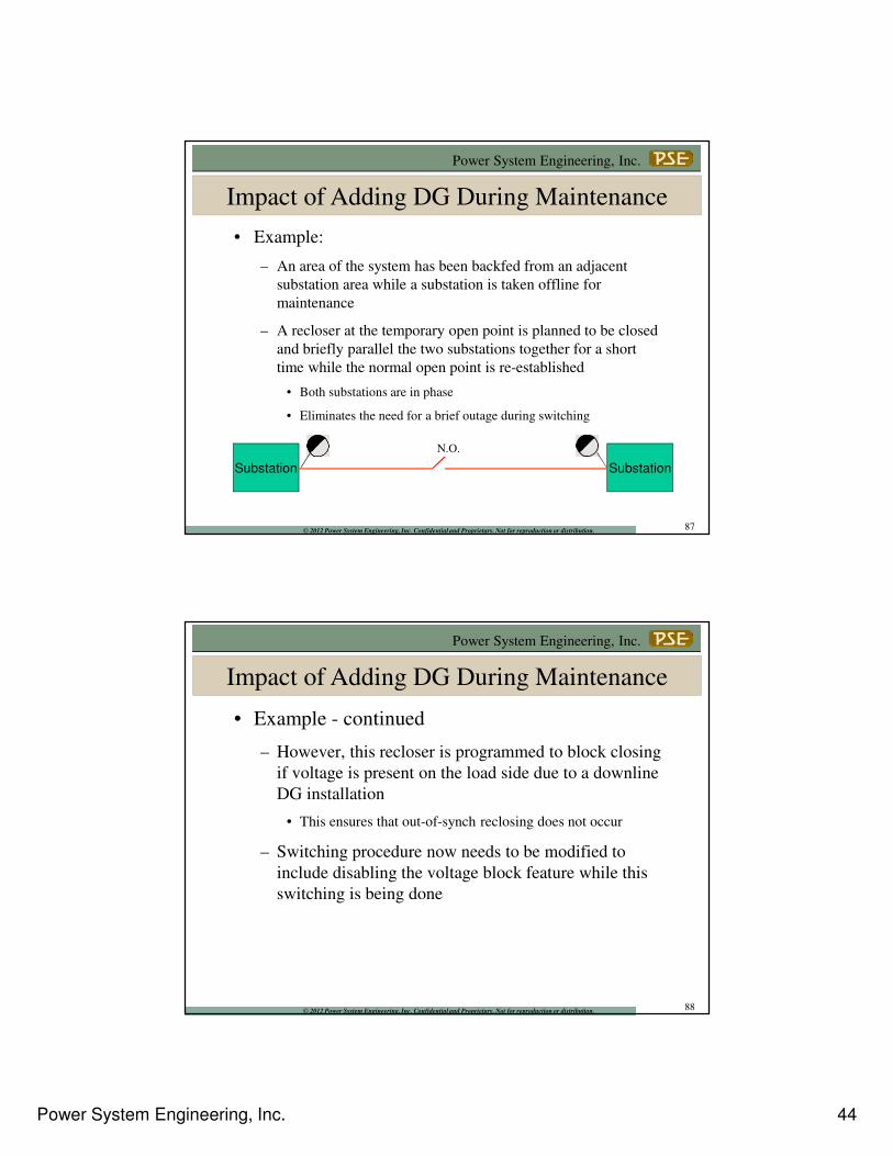
• Example:
– An area of the system has been backfed from an adjacent
substation area while a substation is taken offline for
maintenance
– A recloser at the temporary open point is planned to be closed
and briefly parallel the two substations together for a short
time while the normal open point is re-established
• Both substations are in phase
• Eliminates the need for a brief outage during switching
Substation Substation
N.O.
Impact of Adding DG During Maintenance
87
Power System Engineering, Inc.
© 2012 Power System Engineering, Inc. Confidential and Proprietary. Not for reproduction or distribution.
• Example - continued
– However, this recloser is programmed to block closing
if voltage is present on the load side due to a downline
DG installation
• This ensures that out-of-synch reclosing does not occur
– Switching procedure now needs to be modified to
include disabling the voltage block feature while this
switching is being done
Impact of Adding DG During Maintenance
88
Power System Engineering, Inc. 45
Power System Engineering, Inc.
© 2012 Power System Engineering, Inc. Confidential and Proprietary. Not for reproduction or distribution.
Things We Hope You Take Away…
Interconnection policies and contracts should be put in place if you haven’t already addressed this.
89
Power System Engineering, Inc.
© 2012 Power System Engineering, Inc. Confidential and Proprietary. Not for reproduction or distribution.
Things We Hope You Take Away…
One or more engineering studies may be required to determine any adverse system impacts
– Preliminary review and screening process identifies when studies are required
– Small inverter-based systems certified to meet UL 1741 and IEEE 1547 typically do not require an engineering study
– For interconnections requiring an engineering study, there are a number of review items that may need to be studied
90
Power System Engineering, Inc. 46
Power System Engineering, Inc.
© 2012 Power System Engineering, Inc. Confidential and Proprietary. Not for reproduction or distribution.
Things We Hope You Take Away…
Inspection & Testing of DG systems is important for safety and reliability
– Verify that your technical requirements are being met
– Co-op may need to complete certain commissioning tests to verify correct operation of anti-islanding protection, direct transfer trip schemes, etc.
91
Power System Engineering, Inc.
© 2012 Power System Engineering, Inc. Confidential and Proprietary. Not for reproduction or distribution.
Things We Hope You Take Away…
Maintenance procedures, work practices on the system and switching orders should be reviewed when adding DG to your system and modified as needed.
92
Power System Engineering, Inc. 47
Power System Engineering, Inc.
© 2012 Power System Engineering, Inc. Confidential and Proprietary. Not for reproduction or distribution. 93
Power System Engineering, Inc.
© 2012 Power System Engineering, Inc. Confidential and Proprietary. Not for reproduction or distribution. 94
Power System Engineering, Inc.
Name: Jeff Triplett, P.E.
Title: Utility System Consultant
Direct: (740) 568-9220 x10
Mobile: (740) 525-0070
Email: [email protected]
Thank You: