Embed Size (px)
DESCRIPTION
Distributed Components, Model Driven Engineering & Specification Formalisms. Eric Madelaine [email protected] INRIA Sophia-Antipolis Oasis team. Goals of the Course. Understand the place of formal methods in the software design cycle - PowerPoint PPT Presentation
Citation preview

Mastere Ubinet -- UNS -- oct. 2010
Distributed Components,Model Driven Engineering &
Specification Formalisms
Eric [email protected]
INRIA Sophia-AntipolisOasis team

Mastere Ubinet -- UNS -- oct. 2010
Goals of the Course
1. Understand the place of formal methods in the software design cycle
2. Have a glimpse at a variety of modeling aspects
3. Learn about component-based software architecture
4. Explore one example of a component modeling tool

Mastere Ubinet -- UNS -- oct. 2010
AGENDA
• Vocabulary specification, modeling, testing, verification…: Formal methods in the design flow of distributed/embedded systems
• Graphical Modeling Languages a zoo of UML diagrams
• Components models : Fractal, GCM
• Tool for component-based software modeling Vercors Component Environment

Mastere Ubinet -- UNS -- oct. 2010
Formal methods
Formal methods :• Provide mathematical semantics to models so that their relation to implemented product can be asserted and proved :
– specification formalisms, (temporal) logics– model checking, equivalence checking– certification, testing– model-based test generation
• Modeling languages: – UML and variants (StateCharts, SysML,…)– Dedicated IDLs and ADLs for system decomposition (…)– Assertion languages (annotations)

Mastere Ubinet -- UNS -- oct. 2010
Systems: structure and behavior
In general, a system is:
• constituted of components, interacting in a collaborative or hierarchical fashion (structure)
• evolving, as a result of the composed functional of its components (behavior)
a system changes state through time; time is counted in number of actions/operations
• In highly dynamic systems the division is blurred, as structure is transformed by behaviors; e.g. in large scale software services (= business grids, SOA, …)
• rarely the case in embedded systems
See UML and elsewhere, models divided between structural and behavioral ones

Mastere Ubinet -- UNS -- oct. 2010
Design Cycle
Requirements capture
(Initial) specification(Initial) specification
Architectural division
Component design Component design / programming/ programming Component testingComponent testing
Integration
IP component reuse
libraries
Sign-off
Global testing
Implementation

Mastere Ubinet -- UNS -- oct. 2010
Design cycle
Requirements capture
(Initial) specification(Initial) specification
Architectural division
Component testingComponent testing
Integration
IP component reuse
libraries
Sign-off
Global testing
Early specification of Architecture and Interaction
Correct-by-Construction Implementation
Synthesis
Black box specification
Test generation
Proof of requirements
Correct composition: interface compatibility, deadlock freeness, spec implementation

Mastere Ubinet -- UNS -- oct. 2010
AGENDA
• Vocabulary specification, modeling, testing, verification…: Formal methods in the design flow of distributed/embedded systems
• Graphical Modeling Languages a zoo of UML diagrams
• Components models : Fractal, GCM
• Tool for component-based software modeling Vercors Component Environment

Mastere Ubinet -- UNS -- oct. 2010
UML -- MDE -- Visual models
Single (unified) language “Too many different languages, platforms, formalisms….”
• Unified visual Language – Everybody must speak the same language
• Language for specification / code generation– Supposedly precise and non-ambiguous
One single view is not enough:– Class diagrams– Sequence diagrams – Activity diagrams – State machines – Composite structure diagrams – Deployment diagrams – Marte profile

Mastere Ubinet -- UNS -- oct. 2010
A single model is not enough!
• Create several independent models but with common points and relations.
Process View Deployment view
Logical view
Use-Case View
Implementation view
Final userl
Fonctionalité
DevelopersSoftware management
Performance, scalabilité, débitSystem integrators Topologie du système, livraison,
installation, communication
System Engineers
AnalystsStructure

Mastere Ubinet -- UNS -- oct. 2010
Class diagrams

Mastere Ubinet -- UNS -- oct. 2010
Sequence diagram
: Student :Registration Form :Registration Assistant : Courses list:Course Manager
1: Build planning( )
5: Display courses list ( )
2: Get courses list( )
3: Get courses list (Semester)
6: Display empty EDT ( )
4: Get courses list ( )
Choose coursesref
ObjectsActor
Actor instance
MessagesExecution occurrence
Interaction occurrence

Mastere Ubinet -- UNS -- oct. 2010
Activity diagram
Synchronisation(Fork)
Guard
Synchronisation(Join)
Choice
Concurrent executions
Transition
Select course
[ Add course ]
Check planning
Check Pre-requisite
AssignCourse
Solve
Update planning
Del course
[ OK ] KO
[ Del course ]
Action
conflicts

Mastere Ubinet -- UNS -- oct. 2010
State machine diagram
hired
MCF
Prof class 2
Candidate
fail
success
Engineer R&D
H
H
detached
retirement
HDR
promotion
back
Prof class 1

Mastere Ubinet -- UNS -- oct. 2010
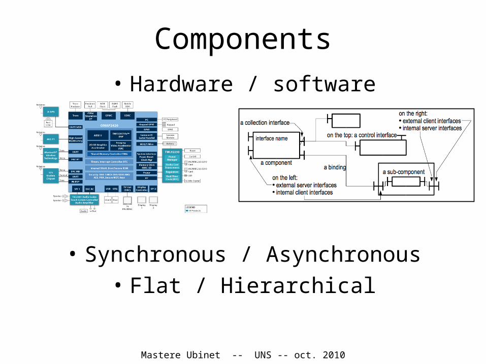
Component andComposite structure diagrams
Hierarchical components
Provided / required interfaces
Ports Bindings

Mastere Ubinet -- UNS -- oct. 2010
Deployment diagram
<<legacy RDBMS>>Apogée
<<Campus LAN>>
<<Campus LAN>><<Campus LAN>>
<<application server>>deptinfo
<<client workstation>>PC
Geisha
<<legacy>>
MatlabSimulateur VHDLEclipse
JDK 1.6
0..2000
1
1
11
1

Mastere Ubinet -- UNS -- oct. 2010
MARTE: UML Profile for Modeling and Analysis of Real-Time and Embedded
Systems
Mastere Ubinet -- UNS -- oct. 2010
UML pro/cons
• Widely accepted, in teaching and in software industry: most computer scientists
• Many proprietary or public-domain tools: modeling, meta-modeling, model transformation, code generation, …
• No precise semantics (specific profiles may give a semantics)
• Opposed to DSL (Domain Specific Languages)… small is beautiful ?

Mastere Ubinet -- UNS -- oct. 2010
AGENDA
• Vocabulary specification, modeling, testing, verification…: Formal methods in the design flow of distributed/embedded systems
• Graphical Modeling Languages a zoo of UML diagrams
• Components models : Fractal, GCM
• Tool for component-based software modeling Vercors Component Environment
Mastere Ubinet -- UNS -- oct. 2010
Components• Hardware / software
• Synchronous / Asynchronous
• Flat / Hierarchical

Mastere Ubinet -- UNS -- oct. 2010
The Fractal project
• Reflective software component model technology for the construction of highly adaptable, and reconfigurable distributed systems– A programming-language independent component model– A set of tools to support programming and assembling– Software industries needs (≠ object-orientation):
Dependencies, assembly, packaging, deployment, configuration
• Open and adaptable/extensible
• Component [Szyperski, 2002]: “A component is a unit of composition with contractually specified interfaces and context dependencies only. A software component can be deployed independently and is subject to composition by third parties.”

Mastere Ubinet -- UNS -- oct. 2010
The Fractalcomponent model
• Systems and middleware engineering– Generic enough to be applied to any other domain– Fine grain (opposed to EJB or CCM), close to a class model– Lightweight (low overhead on top of objects)– Independent from programming languages– Homogeneous vision of all layers (OS, middleware, services, applications)
• Usable as a component framework to build applications – with “standard” Fractal components
• Usable as a component framework framework– building different kinds of components– with minimum introspection and simple aggregation (à la COM)– with binding and lifecycle controllers (à la OSGi)– with a two-level hierarchy and bindings (à la SCA)– with persistence and transaction controllers (à la EJB)– with attribute controllers (à la MBean)

Mastere Ubinet -- UNS -- oct. 2010
FractalComponent
Binding
Interfaces
ProvidedRequired

Mastere Ubinet -- UNS -- oct. 2010
Fractal : controllers
• Control– Non functional (technical) properties– Implemented in the membrane– Made of a set of controllers– E.g. security, transaction, persistence, start/stop,
naming, autonomicity– Controllers accessible through a control interface– Controllers and membranes are open

Mastere Ubinet -- UNS -- oct. 2010
Fractal tools
• Fraclet– programming model based on annotations (within
Java programs)
• Fractal ADL– XML-based architecture description language (ADL)
• Fractal API– set of Java interfaces for
• introspection• reconfiguration• dynamic creation/modification
of Fractal components and component assemblies

Mastere Ubinet -- UNS -- oct. 2010
F4E: Eclipse development environment for Fractal applications
Fractal : development tools

Mastere Ubinet -- UNS -- oct. 2010
GCMGrid Component Model
A Fractal Extension
Scopes and Objectives:Grid/Cloud Codes that Compose and Deploy
No programming, No Scripting, …
Innovations:Abstract Deployment
Multicast and GatherCast
Controller (NF) Components
StandardizationBy the ETSI TC-GRID (2008-2010)

Mastere Ubinet -- UNS -- oct. 2010
GCM: asynchronous model
Distributed components : No shared memory Communication = Remote Method Call Physical infrastructure ≠ logical (virtual) architecture Asynchrony of computation :
Remote Calls are non-blocking
Notion of Future Objects.

Mastere Ubinet -- UNS -- oct. 2010
GCM: NxM communication• 1 to N = multicast / broadcast / scatter• N to 1 bindings = gathercast• Attach a behaviour (policy) to these interfaces

Mastere Ubinet -- UNS -- oct. 2010
GCM: components for controllers
“Componentize” the membrane:• Build controllers in a structured
way• Reuse of controller
components• Applications: control
components for self-optimization, self-healing, self-configuring, interceptors for encryption, authentication, …

Mastere Ubinet -- UNS -- oct. 2010
GCM architecture specifications: VCE tool

Mastere Ubinet -- UNS -- oct. 2010
CBSE approaches, Fractal and GCM
• Component models: Java Beans, EJBeans, Mbeans, Microsoft COM & .Net, OSGI bundles, UML 2.0 Components, Service Component Architecture (SCA), Common Component Architecture (CCA), etc.
• ADLs: Wright, Acme, Rapide, Unicon, C2, Darwin, Room, xArch, ComUnity, OpenCOM, Olan, etc.
• Programming languages: ArchJava, Jiazzi, ComponentJ, Piccola, Scala, etc.
Fractal is a component model: ◮ Programming-language independent:
Many different implementations ◮ Reflective: Components can provide
introspection capabilities ◮ Open: No predefined semantics for
connection, composition and reflectionWith extensible architecture description
language (ADL): ◮ Core ADL for basic concepts ◮ Additional ADL modules for different
architectures
GCM is a compliant extension to Fractal with :
• A specific asynchronous semantics for connection
• Specific communication constructs for collective interfaces
◮ A Java middleware implementation

Mastere Ubinet -- UNS -- oct. 2010
AGENDA
• Vocabulary specification, modeling, testing, verification…: Formal methods in the design flow of distributed/embedded systems
• Graphical Modeling Languages a zoo of UML diagrams
• Components models : Fractal, GCM
• Tool for component-based software modeling Vercors Component Environment

Mastere Ubinet -- UNS -- oct. 2010
VCEVerCors Component Editor
A “Domain Specific Language” for Fractal/GCM– Component architecture diagrams– Behaviour diagrams– Model generation for verification tools– Code generation
Agenda:– Tool architecture– Validation rules– “hands-on” exercices

Mastere Ubinet -- UNS -- oct. 2010
VCEArchitecture
BehavSpecification
(LTS)
Graphical Editor(Eclipse Plugin)
Vercors
GCM/
ProActive
ADL/IDL(final)
Runtime
pNets/Fiacre
ModelGenerator
Finitemodel
Prover

Mastere Ubinet -- UNS -- oct. 2010
VCE Architecture(middle term)
JDCSpecification
Graphical Editor(Eclipse Plugin)
Vercors
JDCFormula
GCM/
ProActive
CodeGenerator
ADL/IDL(final)
JavaSkeletons
Business code
Runtime
pNets/Fiacre
ModelGenerator
Finitemodel
FormulaCompiler
Prover

Mastere Ubinet -- UNS -- oct. 2010
VCEEclipse and MDE Tools
Eclipse Modeling Tools:– EMF (Eclipse Modeling Framework): XMI model definition and
Java code generation– GEF (Graphical Editing Framework)– GMF (Graphical Modeling Framework) for developing graphical
editors– Model Development Tools– Atlas Transformation Language (ATL)– ….

Mastere Ubinet -- UNS -- oct. 2010

Mastere Ubinet -- UNS -- oct. 2010
VCEValidation, OCL
Several notions of correctness in the diagram editors:– Geometric/Structural correctness, by construction: the graphical
tools maintain a number of constraints, like bindings attached to interfaces, interfaces on the box borders, etc.
– Static Semantics: some rules are related to the model structure, not to the graphical objects. E.g. bindings should not cross component levels, or sibling objects should have distinct names…
• There is a “Validation” function (and button), that must be checked only on “finished” diagrams, before model/code generation. It is defined using OCL rules.

Mastere Ubinet -- UNS -- oct. 2010
VCE : Validation, OCLOCL example :
context Binding inv FromClientToServer_InContent_ROLES:( Content.allInstances()->exists(c : Content | c.bindings->includes(self)) and Content.allInstances()->any(bindings->includes(self)).subcomponents
->exists(sc : Component | sc.oclAsType(ComponentDefinition).externalInterfaces->includes(self.sourceInterface))
and Content.allInstances()->any(bindings->includes(self)).subcomponents
->exists(sc : Component | sc.oclAsType(ComponentDefinition).externalInterfaces ->includes(self.targetInterface))
)implies self.sourceInterface.role = InterfaceRole::client
and self.targetInterface.role = InterfaceRole::server

Mastere Ubinet -- UNS -- oct. 2010
Conclusion
1) Modeling formalisms: capture various aspects of software design process
2) Component frameworks: provide method, tools, middleware for programming large-scale applications
3) Vercors: an example of a modeling framework for component-based applications
http://www-sop.inria.fr/oasis/Vercors
There will be at least one studentship proposal in the context of the Vercors plateform.

Mastere Ubinet -- UNS -- oct. 2010
More References
• Fractal:• http://fractal.objectweb.org/doc/ecoop06/Fractal-ECOOP2006-Tutorial.pdf• http://fractal.objectweb.org/tutorials/fractal• (in french) :
http://www-sop.inria.fr/members/Eric.Madelaine/Teaching/Ubinet2010/FractalSeinturier2008.pdf
• GCM:• http://www-sop.inria.fr/members/Eric.Madelaine/Teaching/Ubinet2010/2006-
GCM-GridsWork.ppt• F. Baude, D. Caromel, C. Dalmasso, M. Danelutto, V. Getov, L. Henrio, C.
Perez: GCM: A Grid Extension to Fractal for Autonomous Distributed Components, in Annals of Telecommunications, Vol. 64, no1, jan 2009.
• Vercors:• http://www-sop.inria.fr/oasis/Vercors (papers, download, case-studies)

Mastere Ubinet -- UNS -- oct. 2010
Bonus
• Service-oriented architectures
• Components versus Services
• VCE examples and exercices

Mastere Ubinet -- UNS -- oct. 2010
What is a Service?
• Standardized interface • Self-contained with no dependencies to other
services • available• Little integration need• Coarse-grained• Context-independent
– Services themselves have context
• Allows for Service Composition• Quality of Service(QoS)Attributes which can be
measured

Mastere Ubinet -- UNS -- oct. 2010
Components vs. Services1
• Components– Tight coupling
• Client requires library
– Client / Server– Extendable– Stateless– Fast– Small to medium
granularity
• Services– Loose coupling
• Message exchanges• Policy
– Peer-to-peer– Composable– Context independent– Some overhead– Medium to coarse
granularity
1) From Prof. Schahram Dustdar, S-Cube virtual campus

Mastere Ubinet -- UNS -- oct. 2010
VCEExamples for the SSDE course
Hands-on, Vercors environment
• Component: example, external view• Component: exercise, internal architecture• Multicast: example, workflow style• Multicast: exercise, build a matrix application• Master/slave, example, RPC style• Matrix: example, parameterized style• Diagram correctness: exercise

Mastere Ubinet -- UNS -- oct. 2010
External view

Mastere Ubinet -- UNS -- oct. 2010
Internal architecture(exercise)
Build a composite component, with :• Outside:
– 1 serveur interface SI– 2 client interface CI1, CI2– A number of control (NF) interfaces
• Inside:– 2 subcomponents– One connected to SI– Each connected to one client interface– One binding between them
Check its validity and produce the ADL

Mastere Ubinet -- UNS -- oct. 2010
Multicast and gathercast, workflow style

Mastere Ubinet -- UNS -- oct. 2010
Composite, multicast, matrix (travail à faire en cours)
Build a composite component, with:• One server interface, with an internal multicast
interface• 2 x 3 subcomponents representing matrix
blocks, each linked to its left neighbour

Mastere Ubinet -- UNS -- oct. 2010
Master/slave, RPC style

Mastere Ubinet -- UNS -- oct. 2010
Master/slave, parameterized style

Mastere Ubinet -- UNS -- oct. 2010
Master/slave, parameterized style

Mastere Ubinet -- UNS -- oct. 2010
Master/slave, parameterized style

Mastere Ubinet -- UNS -- oct. 2010
Matrix, parameterized style

Mastere Ubinet -- UNS -- oct. 2010
Exercice• Analyze this diagram (semantics, errors, …)