Embed Size (px)
Citation preview
Distributed By: M&M Control Service, Inc. www.mmcontrol.com/conbraco.php 800-876-0036 847-356-0566
A history ofQuality, Service and Innovation
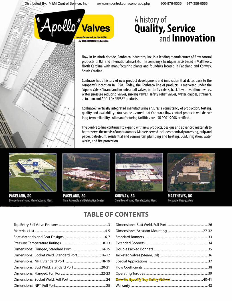
Now in its ninth decade, Conbraco Industries, Inc. is a leading manufacturer of flow control products for U.S. and international markets. The company’s headquarters is based in Matthews, North Carolina with manufacturing plants and foundries located in Pageland and Conway, South Carolina.
Conbraco has a history of new product development and innovation that dates back to the company’s inception in 1928. Today, the Conbraco line of products is marketed under the “Apollo Valves” brand and includes: ball valves, butterfly valves, backflow prevention devices, water pressure reducing valves, mixing valves, safety relief valves, water gauges, strainers, actuation and APOLLOXPRESS® products.
Conbraco’s vertically integrated manufacturing ensures a consistency of production, testing, quality and availability. You can be assured that Conbraco flow control products will deliver long term reliability. All manufacturing facilities are ISO 9001:2008 certified.
The Conbraco line continues to expand with new products, designs and advanced materials to better serve the needs of our customers. Markets served include: chemical processing, pulp and paper, petroleum, residential and commercial plumbing and heating, OEM, irrigation, water works, and fire protection.
Top Entry Ball Valve Features ..............................................................3
Materials List .........................................................................................4-5
Seat Materials and Seat Designs ...................................................6-7
Pressure-Temperature Ratings ................................................... 8-13
Dimensions: Flanged, Standard Port .....................................14-15
Dimensions: Socket Weld, Standard Port .............................16-17
Dimensions: NPT, Standard Port .............................................18-19
Dimensions: Butt Weld, Standard Port ..................................20-21
Dimensions: Flanged, Full Port .................................................22-23
Dimensions: Socket Weld, Full Port ............................................... 24
Dimensions: NPT, Full Port................................................................ 25
Dimensions: Butt Weld, Full Port ................................................... 26
Dimensions: Actuator Mounting .............................................27-32
Standard Bonnets ................................................................................ 33
Extended Bonnets ............................................................................... 34
Double Packed Bonnets ..................................................................... 35
Jacketed Valves (Steam, Oil) ............................................................. 36
Special Applications ........................................................................... 37
Flow Coefficients ................................................................................. 38
Operating Torques ............................................................................... 39
How to Specify Top Entry Valves ........................................40-41
Warranty .................................................................................................. 43
TABLE OF CONTENTS
Distributed By: M&M Control Service, Inc. www.mmcontrol.com/conbraco.php 800-876-0036 847-356-0566
TOP ENTRY BALL VALVES
800-876-0036 847-356-05663
TOP ENTRY ADVANTAGES:
£ Self-Adjusting Seats: Compensate for Wear & Temperature Fluctuations
£ Spring Loaded Low Pressure Seals
£ Pressure Activated Seating
£ Built-In Antistatic Feature
£ Simplified In-line Service
£ Minimal Potential Leak Paths
£ ISO 5211 Mounting Pad
NO SURPRISES
Apollo’s Top Entry Ball Valves offer more. In addition to the three things everyone has come to expect from Apollo: high quality products, competitive pricing and on time delivery, Apollo Top Entry Valves deliver additional premiums; a broader choice of material for both internal and external components, more optional features to choose from, and selectable seal material combinations all resulting in an expanded serviceable application range.
FIT FOR PURPOSE
These premiums can be combined to create a product uniquely tailored to customer specifications and applications. These additional options allow a valve to be selected without compromising critical performance requirements or operating conveniences and without adding unnecessary features and the costs associated with them.
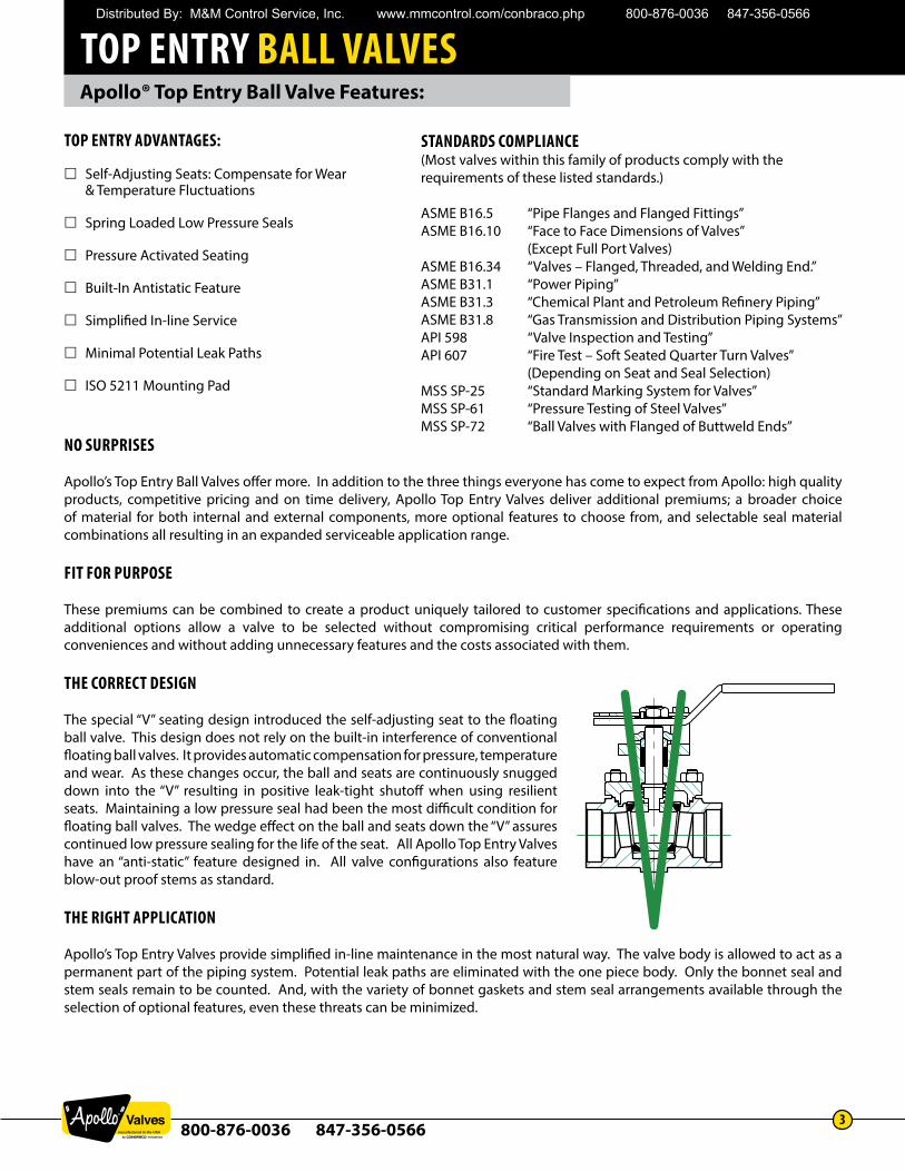
THE CORRECT DESIGN
The special “V” seating design introduced the self-adjusting seat to the floating ball valve. This design does not rely on the built-in interference of conventional floating ball valves. It provides automatic compensation for pressure, temperature and wear. As these changes occur, the ball and seats are continuously snugged down into the “V” resulting in positive leak-tight shutoff when using resilient seats. Maintaining a low pressure seal had been the most difficult condition for floating ball valves. The wedge effect on the ball and seats down the “V” assures continued low pressure sealing for the life of the seat. All Apollo Top Entry Valves have an “anti-static” feature designed in. All valve configurations also feature blow-out proof stems as standard.
THE RIGHT APPLICATION
Apollo’s Top Entry Valves provide simplified in-line maintenance in the most natural way. The valve body is allowed to act as a permanent part of the piping system. Potential leak paths are eliminated with the one piece body. Only the bonnet seal and stem seals remain to be counted. And, with the variety of bonnet gaskets and stem seal arrangements available through the selection of optional features, even these threats can be minimized.
Apollo® Top Entry Ball Valve Features:
STANDARDS COMPLIANCE(Most valves within this family of products comply with the requirements of these listed standards.)
ASME B16.5 “Pipe Flanges and Flanged Fittings”ASME B16.10 “Face to Face Dimensions of Valves”
(Except Full Port Valves)ASME B16.34 “Valves – Flanged, Threaded, and Welding End.”ASME B31.1 “Power Piping”ASME B31.3 “Chemical Plant and Petroleum Refinery Piping”ASME B31.8 “Gas Transmission and Distribution Piping Systems”API 598 “Valve Inspection and Testing”API 607 “Fire Test – Soft Seated Quarter Turn Valves”
(Depending on Seat and Seal Selection)MSS SP-25 “Standard Marking System for Valves”MSS SP-61 “Pressure Testing of Steel Valves”MSS SP-72 “Ball Valves with Flanged of Buttweld Ends”
Distributed By: M&M Control Service, Inc. www.mmcontrol.com/conbraco.php 800-876-0036 847-356-0566
TOP ENTRY BALL VALVES
800-876-0036 847-356-05664
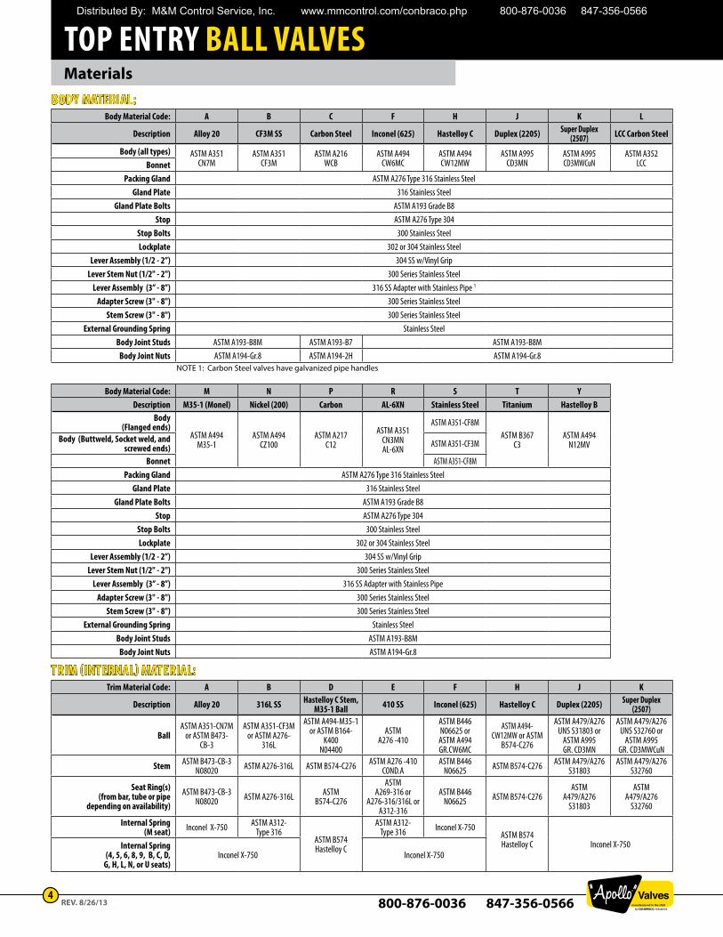
MaterialsBODY MATERIAL:
Body Material Code: A B C F H J K L
Description Alloy 20 CF3M SS Carbon Steel Inconel (625) Hastelloy C Duplex (2205) Super Duplex (2507) LCC Carbon Steel
Body (all types) ASTM A351CN7M
ASTM A351CF3M
ASTM A216WCB
ASTM A494CW6MC
ASTM A494CW12MW
ASTM A995CD3MN
ASTM A995CD3MWCuN
ASTM A352LCCBonnet
Packing Gland ASTM A276 Type 316 Stainless SteelGland Plate 316 Stainless Steel
Gland Plate Bolts ASTM A193 Grade B8Stop ASTM A276 Type 304
Stop Bolts 300 Stainless SteelLockplate 302 or 304 Stainless Steel
Lever Assembly (1/2 - 2”) 304 SS w/Vinyl GripLever Stem Nut (1/2" - 2") 300 Series Stainless Steel
Lever Assembly (3” - 8”) 316 SS Adapter with Stainless Pipe 1
Adapter Screw (3" - 8") 300 Series Stainless SteelStem Screw (3" - 8") 300 Series Stainless Steel
External Grounding Spring Stainless SteelBody Joint Studs ASTM A193-B8M ASTM A193-B7 ASTM A193-B8M
Body Joint Nuts ASTM A194-Gr.8 ASTM A194-2H ASTM A194-Gr.8NOTE 1: Carbon Steel valves have galvanized pipe handles
Body Material Code: M N P R S T YDescription M35-1 (Monel) Nickel (200) Carbon AL-6XN Stainless Steel Titanium Hastelloy B
Body(Flanged ends)
ASTM A494M35-1
ASTM A494CZ100
ASTM A217C12
ASTM A351CN3MN AL-6XN
ASTM A351-CF8MASTM B367
C3ASTM A494
N12MVBody (Buttweld, Socket weld, and
screwed ends) ASTM A351-CF3M
Bonnet ASTM A351-CF8MPacking Gland ASTM A276 Type 316 Stainless Steel
Gland Plate 316 Stainless SteelGland Plate Bolts ASTM A193 Grade B8
Stop ASTM A276 Type 304Stop Bolts 300 Stainless SteelLockplate 302 or 304 Stainless Steel
Lever Assembly (1/2 - 2”) 304 SS w/Vinyl GripLever Stem Nut (1/2" - 2") 300 Series Stainless Steel
Lever Assembly (3” - 8”) 316 SS Adapter with Stainless PipeAdapter Screw (3" - 8") 300 Series Stainless Steel
Stem Screw (3" - 8") 300 Series Stainless SteelExternal Grounding Spring Stainless Steel
Body Joint Studs ASTM A193-B8MBody Joint Nuts ASTM A194-Gr.8
TRIM (INTERNAL) MATERIAL:Trim Material Code: A B D E F H J K
Description Alloy 20 316L SS Hastelloy C Stem, M35-1 Ball 410 SS Inconel (625) Hastelloy C Duplex (2205) Super Duplex
(2507)
BallASTM A351-CN7M
or ASTM B473-CB-3
ASTM A351-CF3M or ASTM A276-
316L
ASTM A494-M35-1 or ASTM B164-
K400N04400
ASTMA276 -410
ASTM B446N06625 or
ASTM A494GR.CW6MC
ASTM A494-CW12MW or ASTM
B574-C276
ASTM A479/A276UNS S31803 or
ASTM A995GR. CD3MN
ASTM A479/A276UNS S32760 or
ASTM A995GR. CD3MWCuN
Stem ASTM B473-CB-3N08020 ASTM A276-316L ASTM B574-C276 ASTM A276 -410
COND.AASTM B446
N06625 ASTM B574-C276 ASTM A479/A276S31803
ASTM A479/A276S32760
Seat Ring(s) (from bar, tube or pipe
depending on availability)ASTM B473-CB-3
N08020 ASTM A276-316L ASTMB574-C276
ASTMA269-316 or
A276-316/316L orA312-316
ASTM B446N06625 ASTM B574-C276
ASTMA479/A276
S31803
ASTMA479/A276
S32760
Internal Spring (M seat) Inconel X-750 ASTM A312-
Type 316ASTM B574Hastelloy C
ASTM A312-Type 316 Inconel X-750
ASTM B574 Hastelloy C Inconel X-750Internal Spring
(4, 5, 6, 8, 9, B, C, D, G, H, L, N, or U seats)
Inconel X-750 Inconel X-750
REV. 8/26/13
Distributed By: M&M Control Service, Inc. www.mmcontrol.com/conbraco.php 800-876-0036 847-356-0566
TOP ENTRY BALL VALVES
800-876-0036 847-356-05665
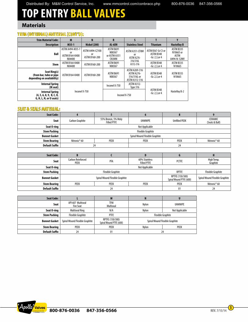
MaterialsTRIM (INTERNAL) MATERIAL (CONT’D):
Trim Material Code: M N R S T YDescription M35-1 Nickel (200) AL-6XN Stainless Steel Titanium Hastelloy B
BallASTM A494-M35-1
orASTM B164-K400
N04400
ASTM A494-CZ100 or
ASTM B160-200
ASTM B691N08367
or ASTM A351 CN3MN
ASTM A351-CF8M or
ASTM A276-316/316LA312-316
ASTM B367-Gr C3 orASTM B348-Gr. 2,3,or 4
ASTM B335N10665 or
ASTM A494-N-12MV
Stem ASTM B164-K400N04400 ASTM B160-200 ASTM B691
N08367ASTM B348-Gr. 2,3,or 4
ASTM B335N10665
Seat Ring(s) (from bar, tube or pipe
depending on availability)ASTM B164-K400 ASTM B160-200 ASTM B691
N08367
ASTM A269-316ASTM A276-316/316L or
ASTM A312-316
ASTM B348-Gr. 2,3,or 4
ASTM B335N10665
Internal Spring (M seat)
Inconel X-750
Inconel X-750 ASTM A312-Type 316
ASTM B348-Gr. 2,3,or 4 Hastelloy B-2Internal Spring
(4, 5, 6, 8, 9, B, C, D, G, H, L, N, or U seats)
Inconel X-750
SEAT & SEALS MATERIAL: Seat Code: 4 5 6 8 9
Seat Carbon Graphite 55% Bronze, 5% Moly Filled PTFE UHMWPE Unfilled PEEK CERAMIC
(Seats & Ball)Seat O-ring Not Applicable
Stem Packing Flexible GraphiteBonnet Gasket Spiral Wound Flexible Graphite
Stem Bearing Nitronic® 60 PEEK PEEK PEEK Nitronic® 60Default Suffix 24 24
Seat Code: B C D G H
Seat Carbon Reinforced PEEK PFA 60% Stainless
Filled PTFE PCTFE High Temp.Graphite
Seat O-ring Not ApplicableStem Packing Flexible Graphite RPTFE Flexible Graphite
Bonnet Gasket Spiral Wound Flexible Graphite RPTFE (150/300)Spiral Wound PTFE (600) Spiral Wound Flexible Graphite
Stem Bearing PEEK PEEK PEEK PEEK Nitronic® 60Default Suffix 24 01 24
Seat Code: L M N U
Seat API 607 MultisealFire Seat
TFMMultiseal Nylon UHMWPE
Seat O-ring Multiseal Ring N/A Nylon Not ApplicableStem Packing Flexible Graphite PTFE Flexible Graphite
Bonnet Gasket Spiral Wound Flexible Graphite RPTFE (150/300)Spiral Wound PTFE (600) Spiral Wound Flexible Graphite
Stem Bearing PEEK PEEK Nylon PEEKDefault Suffix 24 01 24
REV. 7/15/14
Distributed By: M&M Control Service, Inc. www.mmcontrol.com/conbraco.php 800-876-0036 847-356-0566
TOP ENTRY BALL VALVES
800-876-0036 847-356-05666
Seat Materials and Seat Designs
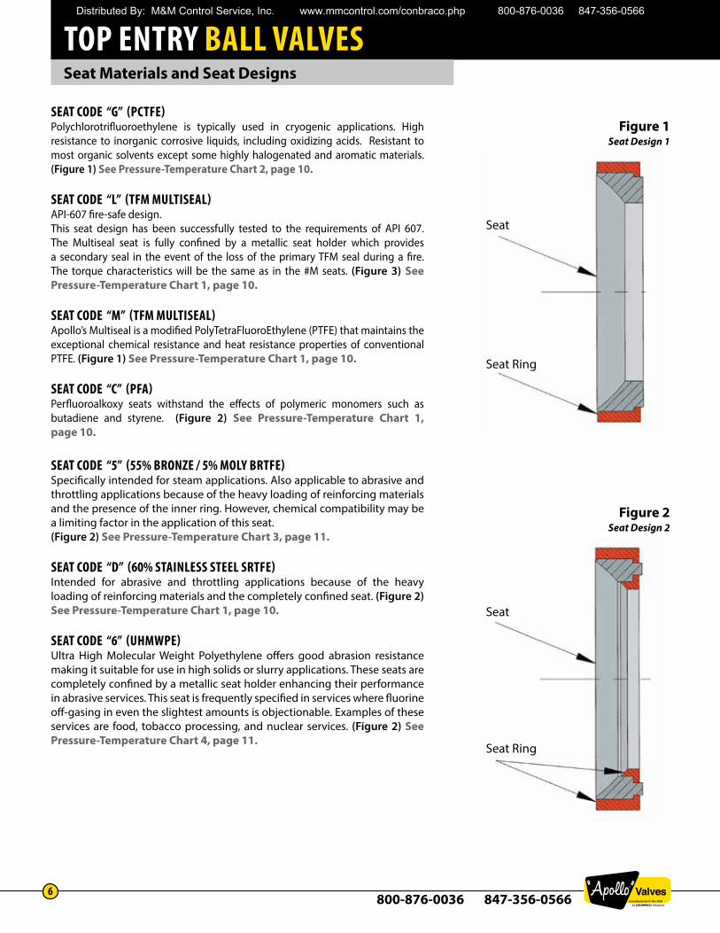
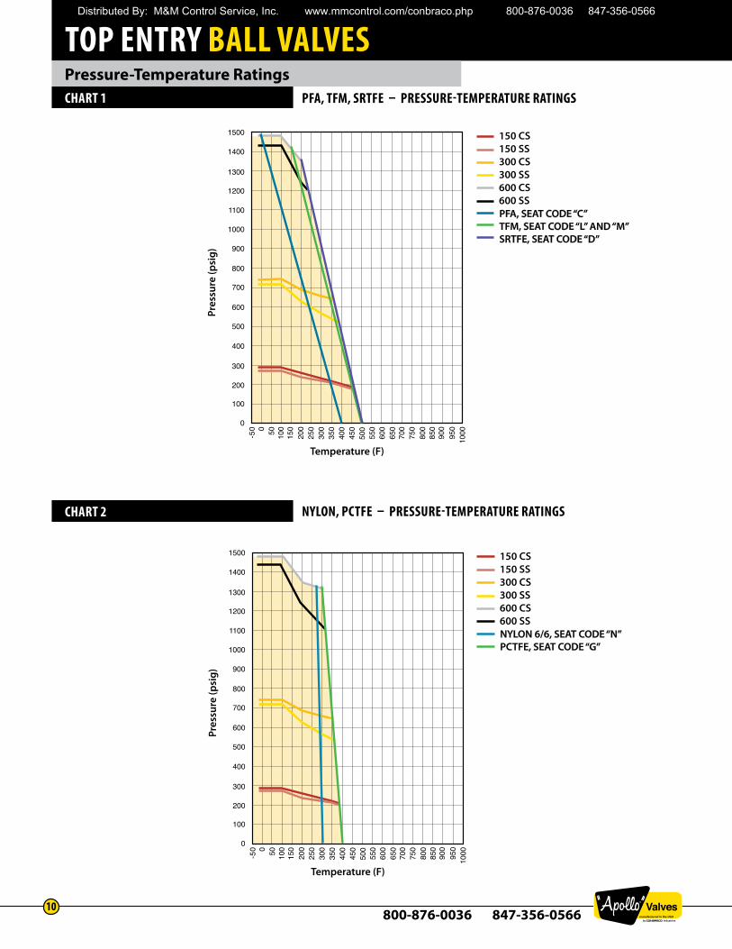
SEAT CODE “G” (PCTFE) Polychlorotrifluoroethylene is typically used in cryogenic applications. High resistance to inorganic corrosive liquids, including oxidizing acids. Resistant to most organic solvents except some highly halogenated and aromatic materials. (Figure 1) See Pressure-Temperature Chart 2, page 10.
SEAT CODE “L” (TFM MULTISEAL) API-607 fire-safe design. This seat design has been successfully tested to the requirements of API 607. The Multiseal seat is fully confined by a metallic seat holder which provides a secondary seal in the event of the loss of the primary TFM seal during a fire. The torque characteristics will be the same as in the #M seats. (Figure 3) See Pressure-Temperature Chart 1, page 10.
SEAT CODE “M” (TFM MULTISEAL) Apollo’s Multiseal is a modified PolyTetraFluoroEthylene (PTFE) that maintains the exceptional chemical resistance and heat resistance properties of conventional PTFE. (Figure 1) See Pressure-Temperature Chart 1, page 10.
SEAT CODE “C” (PFA) Perfluoroalkoxy seats withstand the effects of polymeric monomers such as butadiene and styrene. (Figure 2) See Pressure-Temperature Chart 1, page 10.
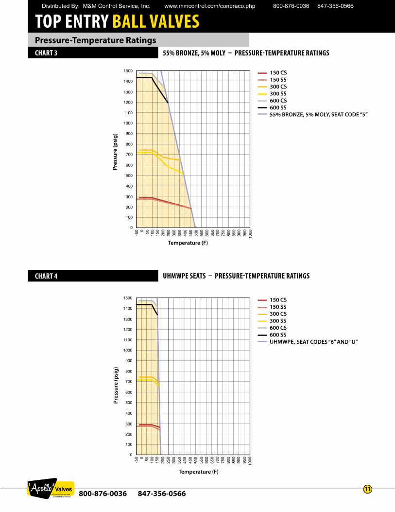
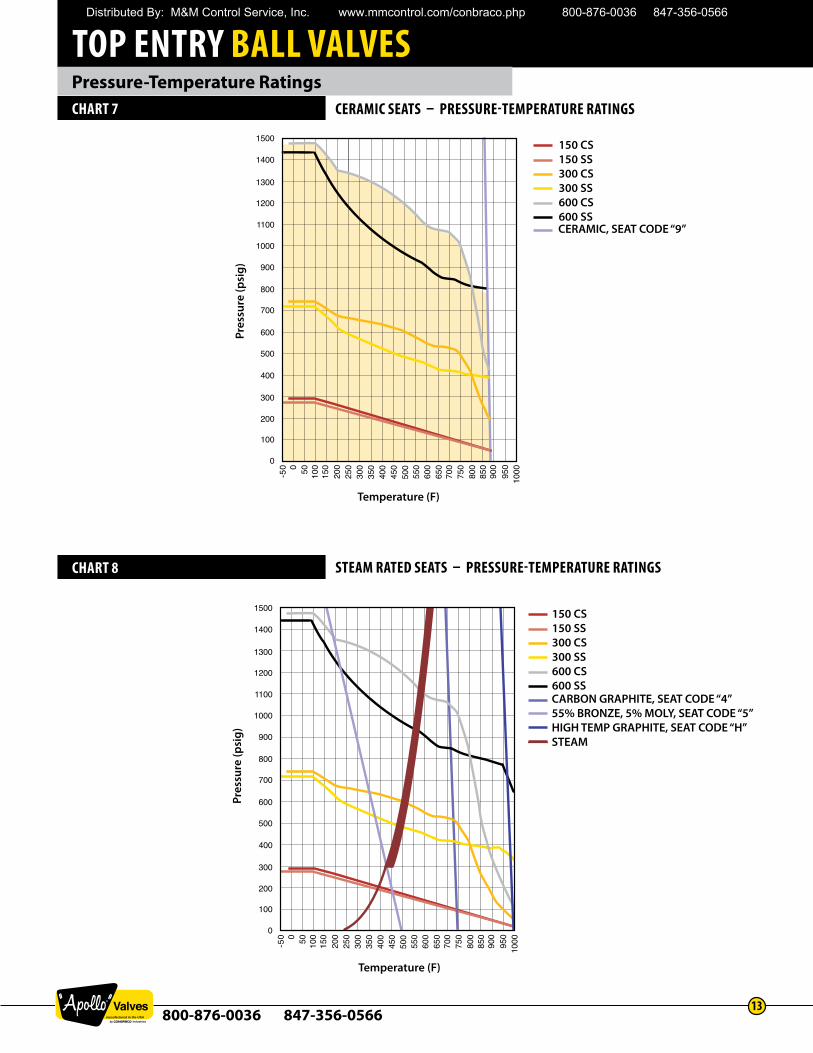
SEAT CODE “5” (55% BRONZE / 5% MOLY BRTFE) Specifically intended for steam applications. Also applicable to abrasive and throttling applications because of the heavy loading of reinforcing materials and the presence of the inner ring. However, chemical compatibility may be a limiting factor in the application of this seat.(Figure 2) See Pressure-Temperature Chart 3, page 11.
SEAT CODE “D” (60% STAINLESS STEEL SRTFE) Intended for abrasive and throttling applications because of the heavy loading of reinforcing materials and the completely confined seat. (Figure 2) See Pressure-Temperature Chart 1, page 10.
SEAT CODE “6” (UHMWPE) Ultra High Molecular Weight Polyethylene offers good abrasion resistance making it suitable for use in high solids or slurry applications. These seats are completely confined by a metallic seat holder enhancing their performance in abrasive services. This seat is frequently specified in services where fluorine off-gasing in even the slightest amounts is objectionable. Examples of these services are food, tobacco processing, and nuclear services. (Figure 2) See Pressure-Temperature Chart 4, page 11.
Seat
Seat Ring
Seat
Seat Ring
Figure 2Seat Design 2
Figure 1Seat Design 1
Distributed By: M&M Control Service, Inc. www.mmcontrol.com/conbraco.php 800-876-0036 847-356-0566
TOP ENTRY BALL VALVES
800-876-0036 847-356-05667
Seat Materials and Seat Designs
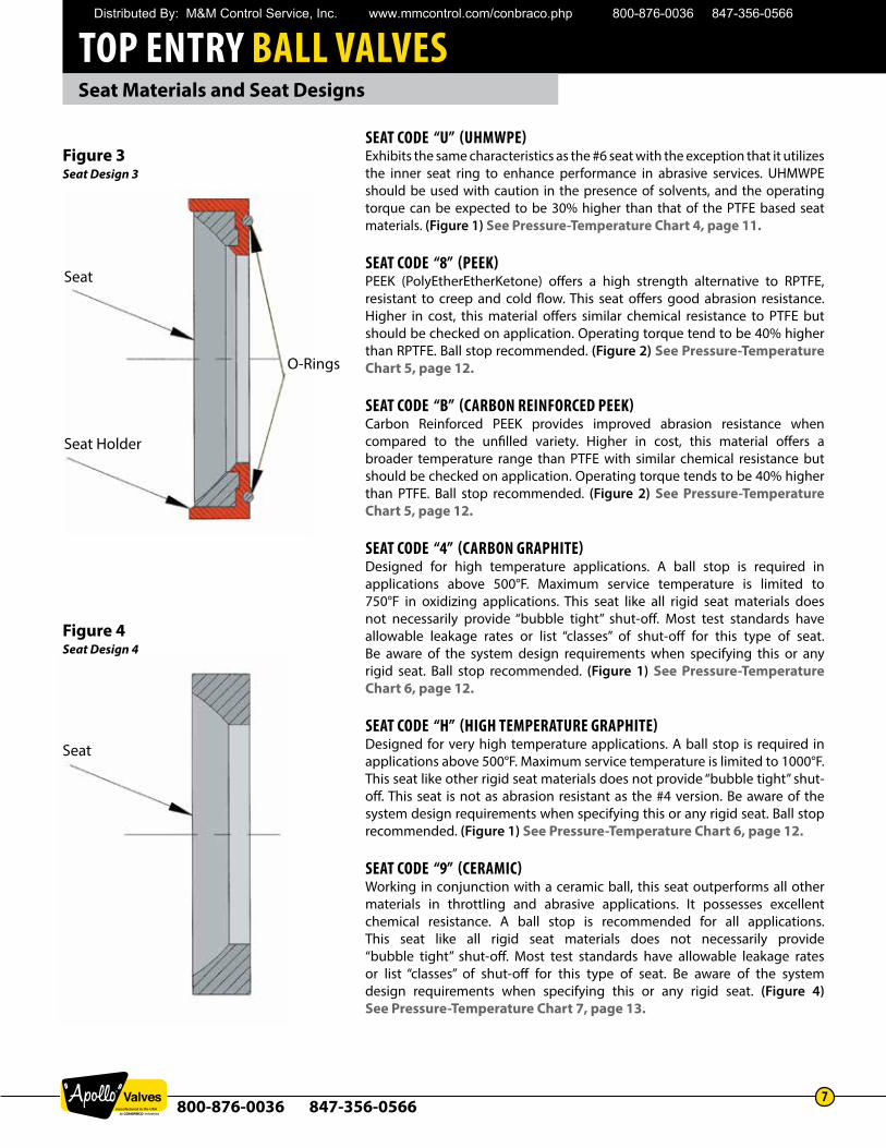
SEAT CODE “U” (UHMWPE) Exhibits the same characteristics as the #6 seat with the exception that it utilizes the inner seat ring to enhance performance in abrasive services. UHMWPE should be used with caution in the presence of solvents, and the operating torque can be expected to be 30% higher than that of the PTFE based seat materials. (Figure 1) See Pressure-Temperature Chart 4, page 11.
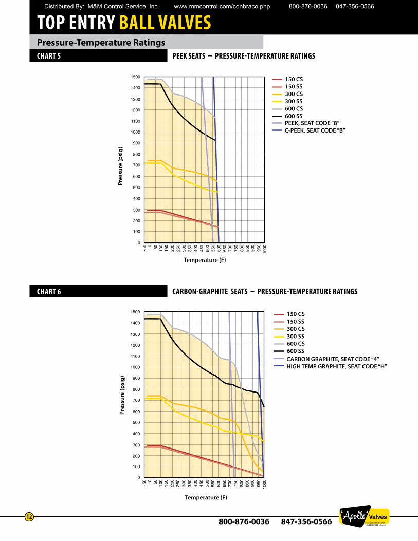
SEAT CODE “8” (PEEK) PEEK (PolyEtherEtherKetone) offers a high strength alternative to RPTFE, resistant to creep and cold flow. This seat offers good abrasion resistance. Higher in cost, this material offers similar chemical resistance to PTFE but should be checked on application. Operating torque tend to be 40% higher than RPTFE. Ball stop recommended. (Figure 2) See Pressure-Temperature Chart 5, page 12.
SEAT CODE “B” (CARBON REINFORCED PEEK) Carbon Reinforced PEEK provides improved abrasion resistance when compared to the unfilled variety. Higher in cost, this material offers a broader temperature range than PTFE with similar chemical resistance but should be checked on application. Operating torque tends to be 40% higher than PTFE. Ball stop recommended. (Figure 2) See Pressure-Temperature Chart 5, page 12.
SEAT CODE “4” (CARBON GRAPHITE) Designed for high temperature applications. A ball stop is required in applications above 500°F. Maximum service temperature is limited to 750°F in oxidizing applications. This seat like all rigid seat materials does not necessarily provide “bubble tight” shut-off. Most test standards have allowable leakage rates or list “classes” of shut-off for this type of seat. Be aware of the system design requirements when specifying this or any rigid seat. Ball stop recommended. (Figure 1) See Pressure-Temperature Chart 6, page 12.
SEAT CODE “H” (HIGH TEMPERATURE GRAPHITE) Designed for very high temperature applications. A ball stop is required in applications above 500°F. Maximum service temperature is limited to 1000°F. This seat like other rigid seat materials does not provide “bubble tight” shut-off. This seat is not as abrasion resistant as the #4 version. Be aware of the system design requirements when specifying this or any rigid seat. Ball stop recommended. (Figure 1) See Pressure-Temperature Chart 6, page 12.
SEAT CODE “9” (CERAMIC) Working in conjunction with a ceramic ball, this seat outperforms all other materials in throttling and abrasive applications. It possesses excellent chemical resistance. A ball stop is recommended for all applications. This seat like all rigid seat materials does not necessarily provide “bubble tight” shut-off. Most test standards have allowable leakage rates or list “classes” of shut-off for this type of seat. Be aware of the system design requirements when specifying this or any rigid seat. (Figure 4) See Pressure-Temperature Chart 7, page 13.
Seat
Seat Holder
O-Rings
Seat
Figure 3Seat Design 3
Figure 4Seat Design 4
Distributed By: M&M Control Service, Inc. www.mmcontrol.com/conbraco.php 800-876-0036 847-356-0566
TOP ENTRY BALL VALVES
800-876-0036 847-356-05668
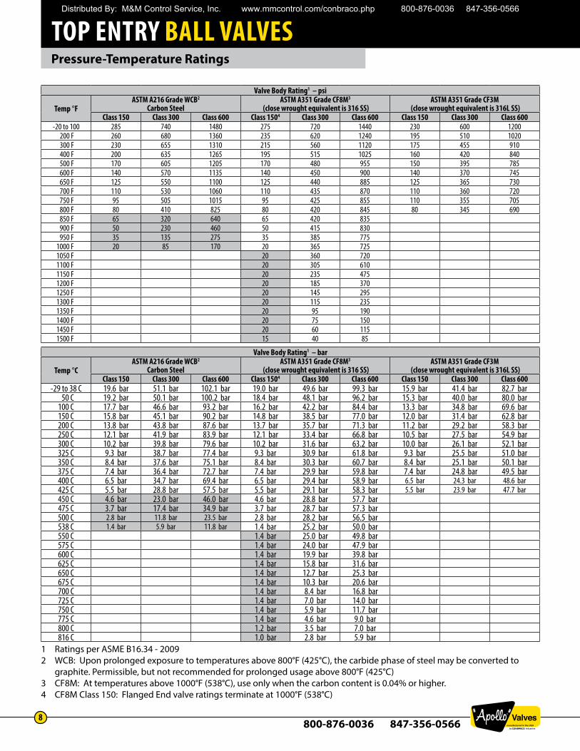
Pressure-Temperature Ratings
Valve Body Rating1 – psi
Temp °FASTM A216 Grade WCB2
Carbon SteelASTM A351 Grade CF8M3
(close wrought equivalent is 316 SS)ASTM A351 Grade CF3M
(close wrought equivalent is 316L SS)Class 150 Class 300 Class 600 Class 1504 Class 300 Class 600 Class 150 Class 300 Class 600
-20 to 100 285 740 1480 275 720 1440 230 600 1200200 F 260 680 1360 235 620 1240 195 510 1020300 F 230 655 1310 215 560 1120 175 455 910400 F 200 635 1265 195 515 1025 160 420 840500 F 170 605 1205 170 480 955 150 395 785600 F 140 570 1135 140 450 900 140 370 745650 F 125 550 1100 125 440 885 125 365 730700 F 110 530 1060 110 435 870 110 360 720750 F 95 505 1015 95 425 855 110 355 705800 F 80 410 825 80 420 845 80 345 690850 F 65 320 640 65 420 835900 F 50 230 460 50 415 830950 F 35 135 275 35 385 775
1000 F 20 85 170 20 365 7251050 F 20 360 7201100 F 20 305 6101150 F 20 235 4751200 F 20 185 3701250 F 20 145 2951300 F 20 115 2351350 F 20 95 1901400 F 20 75 1501450 F 20 60 1151500 F 15 40 85
Valve Body Rating1 – bar
Temp °CASTM A216 Grade WCB2
Carbon SteelASTM A351 Grade CF8M3
(close wrought equivalent is 316 SS)ASTM A351 Grade CF3M
(close wrought equivalent is 316L SS)Class 150 Class 300 Class 600 Class 1504 Class 300 Class 600 Class 150 Class 300 Class 600
-29 to 38 C 19.6 bar 51.1 bar 102.1 bar 19.0 bar 49.6 bar 99.3 bar 15.9 bar 41.4 bar 82.7 bar50 C 19.2 bar 50.1 bar 100.2 bar 18.4 bar 48.1 bar 96.2 bar 15.3 bar 40.0 bar 80.0 bar
100 C 17.7 bar 46.6 bar 93.2 bar 16.2 bar 42.2 bar 84.4 bar 13.3 bar 34.8 bar 69.6 bar150 C 15.8 bar 45.1 bar 90.2 bar 14.8 bar 38.5 bar 77.0 bar 12.0 bar 31.4 bar 62.8 bar200 C 13.8 bar 43.8 bar 87.6 bar 13.7 bar 35.7 bar 71.3 bar 11.2 bar 29.2 bar 58.3 bar250 C 12.1 bar 41.9 bar 83.9 bar 12.1 bar 33.4 bar 66.8 bar 10.5 bar 27.5 bar 54.9 bar300 C 10.2 bar 39.8 bar 79.6 bar 10.2 bar 31.6 bar 63.2 bar 10.0 bar 26.1 bar 52.1 bar325 C 9.3 bar 38.7 bar 77.4 bar 9.3 bar 30.9 bar 61.8 bar 9.3 bar 25.5 bar 51.0 bar350 C 8.4 bar 37.6 bar 75.1 bar 8.4 bar 30.3 bar 60.7 bar 8.4 bar 25.1 bar 50.1 bar375 C 7.4 bar 36.4 bar 72.7 bar 7.4 bar 29.9 bar 59.8 bar 7.4 bar 24.8 bar 49.5 bar400 C 6.5 bar 34.7 bar 69.4 bar 6.5 bar 29.4 bar 58.9 bar 6.5 bar 24.3 bar 48.6 bar425 C 5.5 bar 28.8 bar 57.5 bar 5.5 bar 29.1 bar 58.3 bar 5.5 bar 23.9 bar 47.7 bar450 C 4.6 bar 23.0 bar 46.0 bar 4.6 bar 28.8 bar 57.7 bar475 C 3.7 bar 17.4 bar 34.9 bar 3.7 bar 28.7 bar 57.3 bar500 C 2.8 bar 11.8 bar 23.5 bar 2.8 bar 28.2 bar 56.5 bar538 C 1.4 bar 5.9 bar 11.8 bar 1.4 bar 25.2 bar 50.0 bar550 C 1.4 bar 25.0 bar 49.8 bar575 C 1.4 bar 24.0 bar 47.9 bar600 C 1.4 bar 19.9 bar 39.8 bar625 C 1.4 bar 15.8 bar 31.6 bar650 C 1.4 bar 12.7 bar 25.3 bar675 C 1.4 bar 10.3 bar 20.6 bar700 C 1.4 bar 8.4 bar 16.8 bar725 C 1.4 bar 7.0 bar 14.0 bar750 C 1.4 bar 5.9 bar 11.7 bar775 C 1.4 bar 4.6 bar 9.0 bar800 C 1.2 bar 3.5 bar 7.0 bar816 C 1.0 bar 2.8 bar 5.9 bar
1 Ratings per ASME B16.34 - 20092 WCB: Upon prolonged exposure to temperatures above 800°F (425°C), the carbide phase of steel may be converted to graphite. Permissible, but not recommended for prolonged usage above 800°F (425°C)3 CF8M: At temperatures above 1000°F (538°C), use only when the carbon content is 0.04% or higher. 4 CF8M Class 150: Flanged End valve ratings terminate at 1000°F (538°C)
Distributed By: M&M Control Service, Inc. www.mmcontrol.com/conbraco.php 800-876-0036 847-356-0566
TOP ENTRY BALL VALVES
800-876-0036 847-356-05669
Pressure-Temperature Ratings
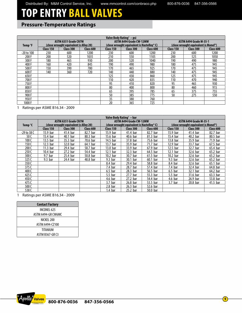
Contact FactoryINCONEL 625
ASTM A494-GR CW6MCNICKEL 200
ASTM A494-CZ100TITANIUM
ASTM B367-GR C3
Valve Body Rating1 – psi
Temp °FASTM A351 Grade CN7M
(close wrought equivalent is Alloy 20)ASTM A494 Grade CW-12MW
(close wrought equivalent is Hastelloy® C)ASTM A494 Grade M-35-1
(close wrought equivalent is Monel®)Class 150 Class 300 Class 600 Class 150 Class 300 Class 600 Class 150 Class 300 Class 600
-20 to 100 230 600 1200 230 600 1200 230 600 1200200 F 200 520 1035 210 550 1105 200 525 1050300 F 180 465 930 200 520 1040 190 490 980400 F 160 420 845 190 490 980 180 475 945500 F 150 390 780 170 465 925 170 475 945600 F 140 360 720 140 440 880 140 475 945650 F 125 430 860 125 475 945700 F 110 420 835 110 470 940750 F 95 410 820 95 465 930800 F 80 400 800 80 460 915850 F 65 395 785 65 375 755900 F 50 385 775 50 275 550950 F 35 380 760
1000 F 20 365 7251 Ratings per ASME B16.34 - 2009
Valve Body Rating1 – bar
Temp °CASTM A351 Grade CN7M
(close wrought equivalent is Alloy 20)ASTM A494 Grade CW-12MW
(close wrought equivalent is Hastelloy® C)ASTM A494 Grade M-35-1
(close wrought equivalent is Monel®)Class 150 Class 300 Class 600 Class 150 Class 300 Class 600 Class 150 Class 300 Class 600
-29 to 38 C 15.9 bar 41.4 bar 82.7 bar 15.9 bar 41.4 bar 82.7 bar 15.9 bar 41.4 bar 82.7 bar50 C 15.4 bar 40.1 bar 80.3 bar 15.6 bar 40.6 bar 81.3 bar 15.4 bar 40.2 bar 80.5 bar
100 C 13.5 bar 35.3 bar 70.6 bar 14.5 bar 37.8 bar 75.6 bar 13.8 bar 35.9 bar 71.9 bar150 C 12.3 bar 32.0 bar 64.1 bar 13.7 bar 35.9 bar 71.7 bar 12.9 bar 33.7 bar 67.5 bar200 C 11.3 bar 29.4 bar 58.7 bar 13.0 bar 33.9 bar 67.9 bar 12.5 bar 32.7 bar 65.4 bar250 C 10.4 bar 27.2 bar 54.4 bar 12.1 bar 32.3 bar 64.5 bar 12.1 bar 32.6 bar 65.2 bar300 C 9.7 bar 25.4 bar 50.8 bar 10.2 bar 30.7 bar 61.5 bar 10.2 bar 32.6 bar 65.2 bar325 C 9.3 bar 24.4 bar 48.8 bar 9.3 bar 30.1 bar 60.1 bar 9.3 bar 32.6 bar 65.2 bar350 C 8.4 bar 29.4 bar 58.8 bar 8.4 bar 32.6 bar 65.1 bar375 C 7.4 bar 28.7 bar 57.4 bar 7.4 bar 32.4 bar 64.8 bar400 C 6.5 bar 28.3 bar 56.5 bar 6.5 bar 32.1 bar 64.2 bar425 C 5.5 bar 27.7 bar 55.3 bar 5.5 bar 31.6 bar 63.3 bar450 C 4.6 bar 27.2 bar 54.4 bar 4.6 bar 26.9 bar 53.8 bar475 C 3.7 bar 26.8 bar 53.5 bar 3.7 bar 20.8 bar 41.5 bar500 C 2.8 bar 26.3 bar 52.6 bar538 C 1.4 bar 25.2 bar 50.0 bar
1 Ratings per ASME B16.34 - 2009
Distributed By: M&M Control Service, Inc. www.mmcontrol.com/conbraco.php 800-876-0036 847-356-0566
TOP ENTRY BALL VALVES
800-876-0036 847-356-056610
Pressure-Temperature RatingsCHART 1 PFA, TFM, SRTFE – PRESSURE-TEMPERATURE RATINGS
CHART 2 NYLON, PCTFE – PRESSURE-TEMPERATURE RATINGS
Distributed By: M&M Control Service, Inc. www.mmcontrol.com/conbraco.php 800-876-0036 847-356-0566
TOP ENTRY BALL VALVES
800-876-0036 847-356-056611
Pressure-Temperature RatingsCHART 3 55% BRONZE, 5% MOLY – PRESSURE-TEMPERATURE RATINGS
CHART 4 UHMWPE SEATS – PRESSURE-TEMPERATURE RATINGS
Distributed By: M&M Control Service, Inc. www.mmcontrol.com/conbraco.php 800-876-0036 847-356-0566
TOP ENTRY BALL VALVES
800-876-0036 847-356-056612
Pressure-Temperature RatingsCHART 5 PEEK SEATS – PRESSURE-TEMPERATURE RATINGS
CHART 6 CARBON-GRAPHITE SEATS – PRESSURE-TEMPERATURE RATINGS
Distributed By: M&M Control Service, Inc. www.mmcontrol.com/conbraco.php 800-876-0036 847-356-0566
TOP ENTRY BALL VALVES
800-876-0036 847-356-056613
Pressure-Temperature RatingsCHART 7 CERAMIC SEATS – PRESSURE-TEMPERATURE RATINGS
CHART 8 STEAM RATED SEATS – PRESSURE-TEMPERATURE RATINGS
Distributed By: M&M Control Service, Inc. www.mmcontrol.com/conbraco.php 800-876-0036 847-356-0566
TOP ENTRY BALL VALVES
800-876-0036 847-356-056614
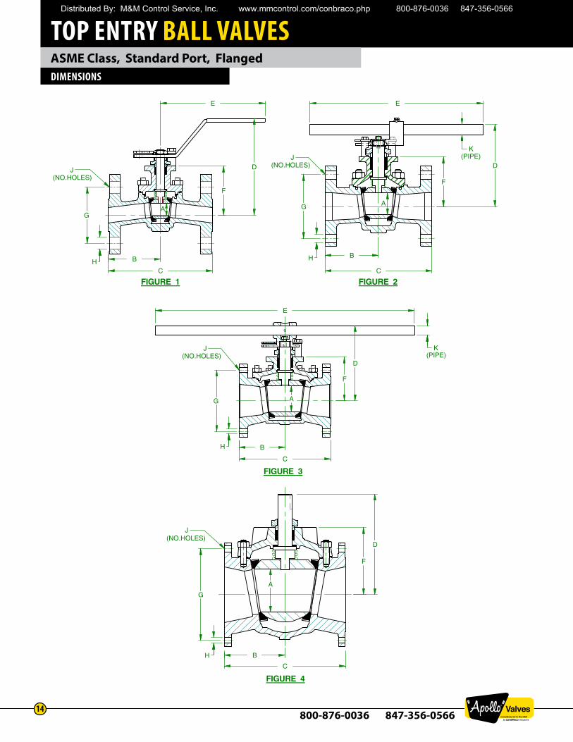
ASME Class, Standard Port, FlangedDIMENSIONS
D D
D
E E
G G
G
B
C
B
C
B
C
A
J
J
J
J
FIGURE 1
FIGURE 3
FIGURE 4
F
F
F(NO.HOLES)
(NO.HOLES)
(NO.HOLES)
(NO.HOLES)
E
C
B
G A
HH
H
H
D
F
K
K
(PIPE)
(PIPE)
AA
FIGURE 2
Distributed By: M&M Control Service, Inc. www.mmcontrol.com/conbraco.php 800-876-0036 847-356-0566
TOP ENTRY BALL VALVES
800-876-0036 847-356-056615
ASME Class, Standard Port, FlangedDIMENSIONS
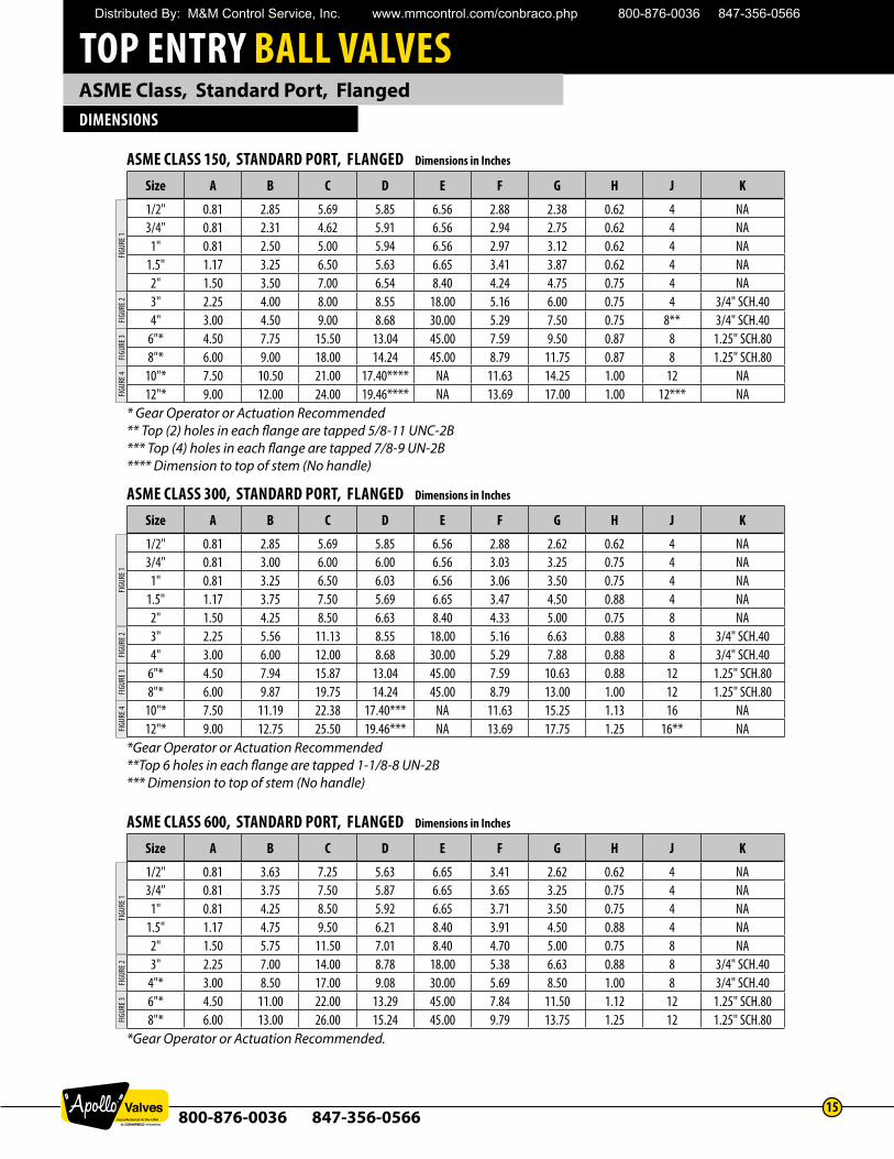
ASME CLASS 150, STANDARD PORT, FLANGED Dimensions in Inches
Size A B C D E F G H J K
1/2" 0.81 2.85 5.69 5.85 6.56 2.88 2.38 0.62 4 NA3/4" 0.81 2.31 4.62 5.91 6.56 2.94 2.75 0.62 4 NA
1" 0.81 2.50 5.00 5.94 6.56 2.97 3.12 0.62 4 NA1.5" 1.17 3.25 6.50 5.63 6.65 3.41 3.87 0.62 4 NA2" 1.50 3.50 7.00 6.54 8.40 4.24 4.75 0.75 4 NA3" 2.25 4.00 8.00 8.55 18.00 5.16 6.00 0.75 4 3/4" SCH.404" 3.00 4.50 9.00 8.68 30.00 5.29 7.50 0.75 8** 3/4" SCH.40
6"* 4.50 7.75 15.50 13.04 45.00 7.59 9.50 0.87 8 1.25" SCH.808"* 6.00 9.00 18.00 14.24 45.00 8.79 11.75 0.87 8 1.25" SCH.80
10"* 7.50 10.50 21.00 17.40**** NA 11.63 14.25 1.00 12 NA12"* 9.00 12.00 24.00 19.46**** NA 13.69 17.00 1.00 12*** NA
* Gear Operator or Actuation Recommended** Top (2) holes in each flange are tapped 5/8-11 UNC-2B *** Top (4) holes in each flange are tapped 7/8-9 UN-2B **** Dimension to top of stem (No handle)
FIGUR
E 1FIG
URE 2
FIGUR
E 3FIG
URE 4
ASME CLASS 300, STANDARD PORT, FLANGED Dimensions in Inches
Size A B C D E F G H J K
1/2" 0.81 2.85 5.69 5.85 6.56 2.88 2.62 0.62 4 NA3/4" 0.81 3.00 6.00 6.00 6.56 3.03 3.25 0.75 4 NA
1" 0.81 3.25 6.50 6.03 6.56 3.06 3.50 0.75 4 NA1.5" 1.17 3.75 7.50 5.69 6.65 3.47 4.50 0.88 4 NA2" 1.50 4.25 8.50 6.63 8.40 4.33 5.00 0.75 8 NA3" 2.25 5.56 11.13 8.55 18.00 5.16 6.63 0.88 8 3/4" SCH.404" 3.00 6.00 12.00 8.68 30.00 5.29 7.88 0.88 8 3/4" SCH.40
6"* 4.50 7.94 15.87 13.04 45.00 7.59 10.63 0.88 12 1.25" SCH.808"* 6.00 9.87 19.75 14.24 45.00 8.79 13.00 1.00 12 1.25" SCH.80
10"* 7.50 11.19 22.38 17.40*** NA 11.63 15.25 1.13 16 NA12"* 9.00 12.75 25.50 19.46*** NA 13.69 17.75 1.25 16** NA
*Gear Operator or Actuation Recommended**Top 6 holes in each flange are tapped 1-1/8-8 UN-2B *** Dimension to top of stem (No handle)
FIGUR
E 1FIG
URE 2
FIGUR
E 3FIG
URE 4
ASME CLASS 600, STANDARD PORT, FLANGED Dimensions in Inches
Size A B C D E F G H J K
1/2" 0.81 3.63 7.25 5.63 6.65 3.41 2.62 0.62 4 NA3/4" 0.81 3.75 7.50 5.87 6.65 3.65 3.25 0.75 4 NA
1" 0.81 4.25 8.50 5.92 6.65 3.71 3.50 0.75 4 NA1.5" 1.17 4.75 9.50 6.21 8.40 3.91 4.50 0.88 4 NA2" 1.50 5.75 11.50 7.01 8.40 4.70 5.00 0.75 8 NA3" 2.25 7.00 14.00 8.78 18.00 5.38 6.63 0.88 8 3/4" SCH.40
4"* 3.00 8.50 17.00 9.08 30.00 5.69 8.50 1.00 8 3/4" SCH.406"* 4.50 11.00 22.00 13.29 45.00 7.84 11.50 1.12 12 1.25" SCH.808"* 6.00 13.00 26.00 15.24 45.00 9.79 13.75 1.25 12 1.25" SCH.80
*Gear Operator or Actuation Recommended.
FIGUR
E 1FIG
URE 2
FIGUR
E 3
Distributed By: M&M Control Service, Inc. www.mmcontrol.com/conbraco.php 800-876-0036 847-356-0566
TOP ENTRY BALL VALVES
800-876-0036 847-356-056616
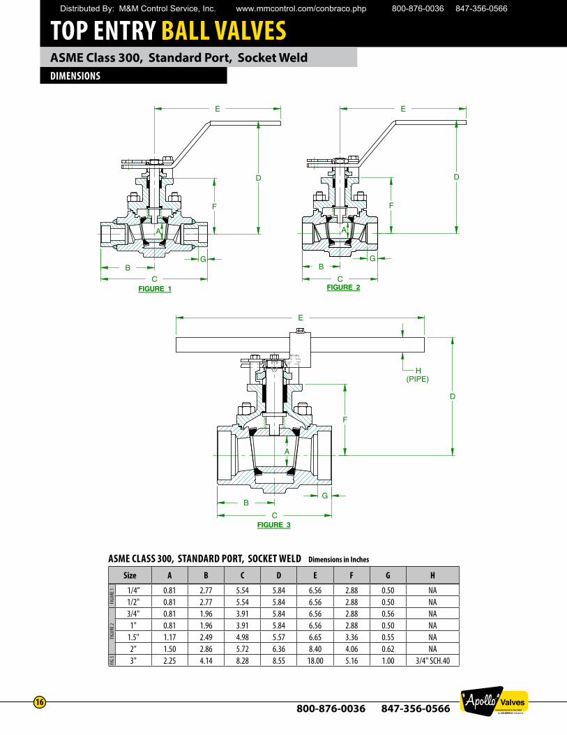
ASME Class 300, Standard Port, Socket WeldDIMENSIONS
FIGURE 3
FIGURE 2
E E
C
B
C
D
F F
B G G
E
B
C
G
A
F
D
FIGURE 1
H(PIPE)
D
A A
ASME CLASS 300, STANDARD PORT, SOCKET WELD Dimensions in Inches
Size A B C D E F G H
1/4” 0.81 2.77 5.54 5.84 6.56 2.88 0.50 NA1/2" 0.81 2.77 5.54 5.84 6.56 2.88 0.50 NA3/4" 0.81 1.96 3.91 5.84 6.56 2.88 0.56 NA
1" 0.81 1.96 3.91 5.84 6.56 2.88 0.50 NA1.5" 1.17 2.49 4.98 5.57 6.65 3.36 0.55 NA2" 1.50 2.86 5.72 6.36 8.40 4.06 0.62 NA3" 2.25 4.14 8.28 8.55 18.00 5.16 1.00 3/4" SCH.40
FIGUR
E 1FIG
URE 2
FIG 3
Distributed By: M&M Control Service, Inc. www.mmcontrol.com/conbraco.php 800-876-0036 847-356-0566
TOP ENTRY BALL VALVES
800-876-0036 847-356-056617
ASME Class 600, Standard Port, Socket WeldDIMENSIONS
FIGURE 1
E
C B
G
D
F
E
D
F
G
C B
FIGURE 2
A A
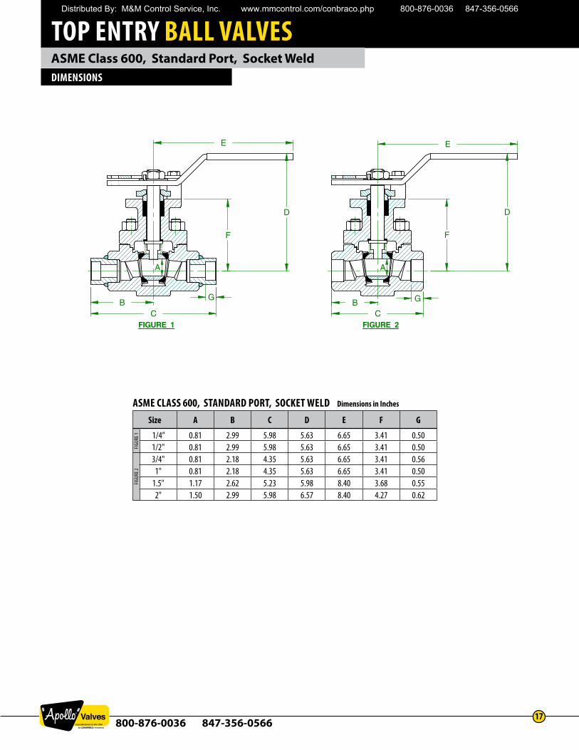
ASME CLASS 600, STANDARD PORT, SOCKET WELD Dimensions in Inches
Size A B C D E F G
1/4” 0.81 2.99 5.98 5.63 6.65 3.41 0.501/2" 0.81 2.99 5.98 5.63 6.65 3.41 0.503/4" 0.81 2.18 4.35 5.63 6.65 3.41 0.56
1" 0.81 2.18 4.35 5.63 6.65 3.41 0.501.5" 1.17 2.62 5.23 5.98 8.40 3.68 0.552" 1.50 2.99 5.98 6.57 8.40 4.27 0.62
FIGUR
E 1FIG
URE 2
Distributed By: M&M Control Service, Inc. www.mmcontrol.com/conbraco.php 800-876-0036 847-356-0566
TOP ENTRY BALL VALVES
800-876-0036 847-356-056618
ASME Class 300, Standard Port, NPTDIMENSIONS
FIGURE 3
FIGURE 2FIGURE 1
E
F
D
C
B
E
D
F
C
B
E
C B
F
D
G
A
(PIPE)
A A
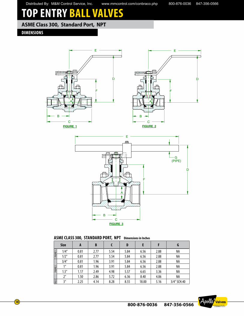
ASME CLASS 300, STANDARD PORT, NPT Dimensions in Inches
Size A B C D E F G
1/4” 0.81 2.77 5.54 5.84 6.56 2.88 NA1/2" 0.81 2.77 5.54 5.84 6.56 2.88 NA3/4" 0.81 1.96 3.91 5.84 6.56 2.88 NA
1" 0.81 1.96 3.91 5.84 6.56 2.88 NA1.5" 1.17 2.49 4.98 5.57 6.65 3.36 NA2" 1.50 2.86 5.72 6.36 8.40 4.06 NA3" 2.25 4.14 8.28 8.55 18.00 5.16 3/4" SCH.40
FIGUR
E 1FIG
URE 2
FIG 3
Distributed By: M&M Control Service, Inc. www.mmcontrol.com/conbraco.php 800-876-0036 847-356-0566
TOP ENTRY BALL VALVES
800-876-0036 847-356-056619
ASME Class 600, Standard Port, NPTDIMENSIONS
E E
C B
C B
F
D D
F
FIGURE 3
NPT NPT
A A
FIGURE 4
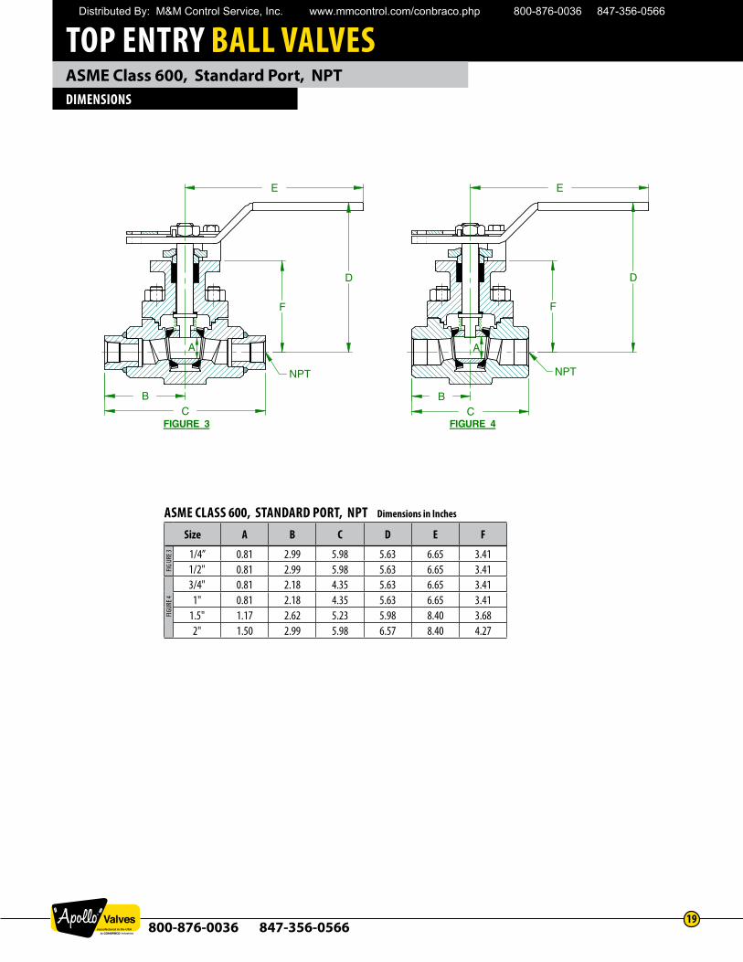
ASME CLASS 600, STANDARD PORT, NPT Dimensions in Inches
Size A B C D E F
1/4” 0.81 2.99 5.98 5.63 6.65 3.411/2" 0.81 2.99 5.98 5.63 6.65 3.413/4" 0.81 2.18 4.35 5.63 6.65 3.41
1" 0.81 2.18 4.35 5.63 6.65 3.411.5" 1.17 2.62 5.23 5.98 8.40 3.682" 1.50 2.99 5.98 6.57 8.40 4.27
FIG U
RE 3
FIGUR
E 4
Distributed By: M&M Control Service, Inc. www.mmcontrol.com/conbraco.php 800-876-0036 847-356-0566
TOP ENTRY BALL VALVES
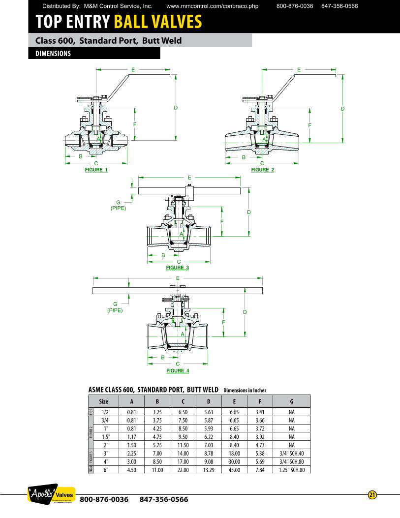
800-876-0036 847-356-056620
Class 300, Standard Port, Butt WeldDIMENSIONS
E E
C B
F
D D
F
C B
E
C B
D
F
G
E
B C
G
F
D
FIGURE 1
FIGURE 3
FIGURE 4
(PIPE)
(PIPE)
FIGURE 2
A A
A
A
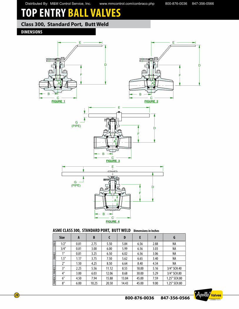
ASME CLASS 300, STANDARD PORT, BUTT WELD Dimensions in Inches
Size A B C D E F G
1/2" 0.81 2.75 5.50 5.84 6.56 2.88 NA3/4" 0.81 3.00 6.00 5.99 6.56 3.03 NA
1" 0.81 3.25 6.50 6.02 6.56 3.06 NA1.5" 1.17 3.75 7.50 5.62 6.65 3.40 NA2" 1.50 4.25 8.50 6.64 8.40 4.34 NA3" 2.25 5.56 11.12 8.55 18.00 5.16 3/4" SCH.404" 3.00 6.03 12.06 8.68 30.00 5.29 3/4" SCH.806" 4.50 7.94 15.88 13.04 45.00 7.59 1.25" SCH.808" 6.00 10.25 20.50 14.43 45.00 9.00 1.25" SCH.80
FIG 1
FIGUR
E 2FIG
URE 3
FIGUR
E 4
Distributed By: M&M Control Service, Inc. www.mmcontrol.com/conbraco.php 800-876-0036 847-356-0566
TOP ENTRY BALL VALVES
800-876-0036 847-356-056621
Class 600, Standard Port, Butt WeldDIMENSIONS
E E
C B
F
D D
F
C B
E
C B
D
F
G
E
B C
G
F
D
FIGURE 1
FIGURE 3
FIGURE 4
(PIPE)
(PIPE)
A A
A
A
FIGURE 2
ASME CLASS 600, STANDARD PORT, BUTT WELD Dimensions in Inches
Size A B C D E F G
1/2" 0.81 3.25 6.50 5.63 6.65 3.41 NA3/4" 0.81 3.75 7.50 5.87 6.65 3.66 NA
1" 0.81 4.25 8.50 5.93 6.65 3.72 NA1.5" 1.17 4.75 9.50 6.22 8.40 3.92 NA2" 1.50 5.75 11.50 7.03 8.40 4.73 NA3" 2.25 7.00 14.00 8.78 18.00 5.38 3/4" SCH.404" 3.00 8.50 17.00 9.08 30.00 5.69 3/4" SCH.806" 4.50 11.00 22.00 13.29 45.00 7.84 1.25" SCH.80
FIG 1
FIGUR
E 2FIG
URE 3
FIG 4
Distributed By: M&M Control Service, Inc. www.mmcontrol.com/conbraco.php 800-876-0036 847-356-0566
TOP ENTRY BALL VALVES
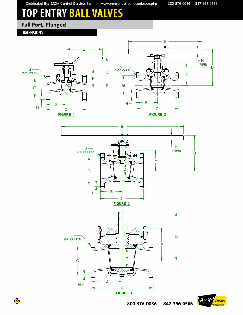
800-876-0036 847-356-056622
Full Port, FlangedDIMENSIONS
FIGURE 1
FIGURE 3
FIGURE 4
G
E
C B
F
D
E
C
B
D
F
G
K
H
JJ
J
J
(NO.HOLES)
(NO.HOLES)
(NO.HOLES)
(NO.HOLES)
(PIPE)
(PIPE)
E
C
A
D
F
G
B
K
H
C
B
D
F
A G
H
AA
FIGURE 2
H
Distributed By: M&M Control Service, Inc. www.mmcontrol.com/conbraco.php 800-876-0036 847-356-0566
TOP ENTRY BALL VALVES
800-876-0036 847-356-056623
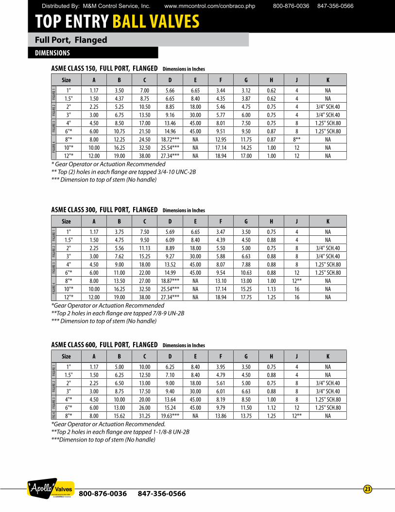
Full Port, FlangedDIMENSIONS
ASME CLASS 300, FULL PORT, FLANGED Dimensions in Inches
Size A B C D E F G H J K
1" 1.17 3.75 7.50 5.69 6.65 3.47 3.50 0.75 4 NA1.5" 1.50 4.75 9.50 6.09 8.40 4.39 4.50 0.88 4 NA2" 2.25 5.56 11.13 8.89 18.00 5.50 5.00 0.75 8 3/4" SCH.403" 3.00 7.62 15.25 9.27 30.00 5.88 6.63 0.88 8 3/4" SCH.404" 4.50 9.00 18.00 13.52 45.00 8.07 7.88 0.88 8 1.25" SCH.80
6"* 6.00 11.00 22.00 14.99 45.00 9.54 10.63 0.88 12 1.25" SCH.808"* 8.00 13.50 27.00 18.87*** NA 13.10 13.00 1.00 12** NA
10"* 10.00 16.25 32.50 25.54*** NA 17.14 15.25 1.13 16 NA12"* 12.00 19.00 38.00 27.34*** NA 18.94 17.75 1.25 16 NA
*Gear Operator or Actuation Recommended**Top 2 holes in each flange are tapped 7/8-9 UN-2B *** Dimension to top of stem (No handle)
FIGUR
E 1FIG
URE 2
FIGUR
E 3FIG
URE 4
ASME CLASS 150, FULL PORT, FLANGED Dimensions in Inches
Size A B C D E F G H J K
1" 1.17 3.50 7.00 5.66 6.65 3.44 3.12 0.62 4 NA1.5" 1.50 4.37 8.75 6.65 8.40 4.35 3.87 0.62 4 NA2" 2.25 5.25 10.50 8.85 18.00 5.46 4.75 0.75 4 3/4" SCH.403" 3.00 6.75 13.50 9.16 30.00 5.77 6.00 0.75 4 3/4" SCH.404" 4.50 8.50 17.00 13.46 45.00 8.01 7.50 0.75 8 1.25" SCH.80
6"* 6.00 10.75 21.50 14.96 45.00 9.51 9.50 0.87 8 1.25" SCH.808"* 8.00 12.25 24.50 18.72*** NA 12.95 11.75 0.87 8** NA
10"* 10.00 16.25 32.50 25.54*** NA 17.14 14.25 1.00 12 NA12"* 12.00 19.00 38.00 27.34*** NA 18.94 17.00 1.00 12 NA
* Gear Operator or Actuation Recommended** Top (2) holes in each flange are tapped 3/4-10 UNC-2B *** Dimension to top of stem (No handle)
FIGUR
E 1FIG
URE 2
FIGUR
E 3FIG
URE 4
ASME CLASS 600, FULL PORT, FLANGED Dimensions in Inches
Size A B C D E F G H J K
1" 1.17 5.00 10.00 6.25 8.40 3.95 3.50 0.75 4 NA1.5" 1.50 6.25 12.50 7.10 8.40 4.79 4.50 0.88 4 NA2" 2.25 6.50 13.00 9.00 18.00 5.61 5.00 0.75 8 3/4" SCH.403" 3.00 8.75 17.50 9.40 30.00 6.01 6.63 0.88 8 3/4" SCH.40
4"* 4.50 10.00 20.00 13.64 45.00 8.19 8.50 1.00 8 1.25" SCH.806"* 6.00 13.00 26.00 15.24 45.00 9.79 11.50 1.12 12 1.25" SCH.808"* 8.00 15.62 31.25 19.63*** NA 13.86 13.75 1.25 12** NA
*Gear Operator or Actuation Recommended.**Top 2 holes in each flange are tapped 1-1/8-8 UN-2B ***Dimension to top of stem (No handle)
FIGUR
E 1FIG
URE 2
FIGUR
E 3FIG
4
Distributed By: M&M Control Service, Inc. www.mmcontrol.com/conbraco.php 800-876-0036 847-356-0566
TOP ENTRY BALL VALVES
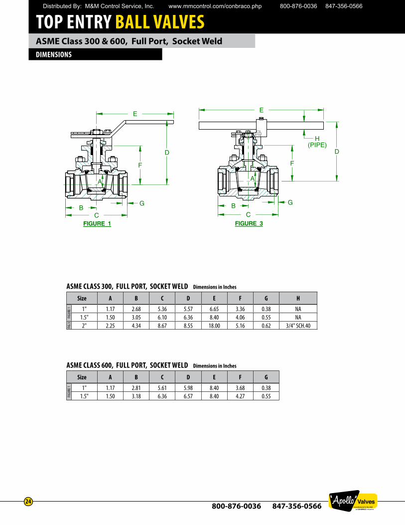
800-876-0036 847-356-056624
ASME Class 300 & 600, Full Port, Socket WeldDIMENSIONS
FIGURE 1
E
C B
G
D
F
E
CB G
D
F
FIGURE 3
H(PIPE)
A
A
FIGURE 1
E
CB
G
D
F
E
C B G
D
F
FIGURE 3
H(PIPE)
A
A
ASME CLASS 300, FULL PORT, SOCKET WELD Dimensions in Inches
Size A B C D E F G H
1" 1.17 2.68 5.36 5.57 6.65 3.36 0.38 NA1.5" 1.50 3.05 6.10 6.36 8.40 4.06 0.55 NA2" 2.25 4.34 8.67 8.55 18.00 5.16 0.62 3/4" SCH.40
FIGUR
E 1FIG
3
ASME CLASS 600, FULL PORT, SOCKET WELD Dimensions in Inches
Size A B C D E F G
1" 1.17 2.81 5.61 5.98 8.40 3.68 0.381.5" 1.50 3.18 6.36 6.57 8.40 4.27 0.55FIG
URE 1
Distributed By: M&M Control Service, Inc. www.mmcontrol.com/conbraco.php 800-876-0036 847-356-0566
TOP ENTRY BALL VALVES
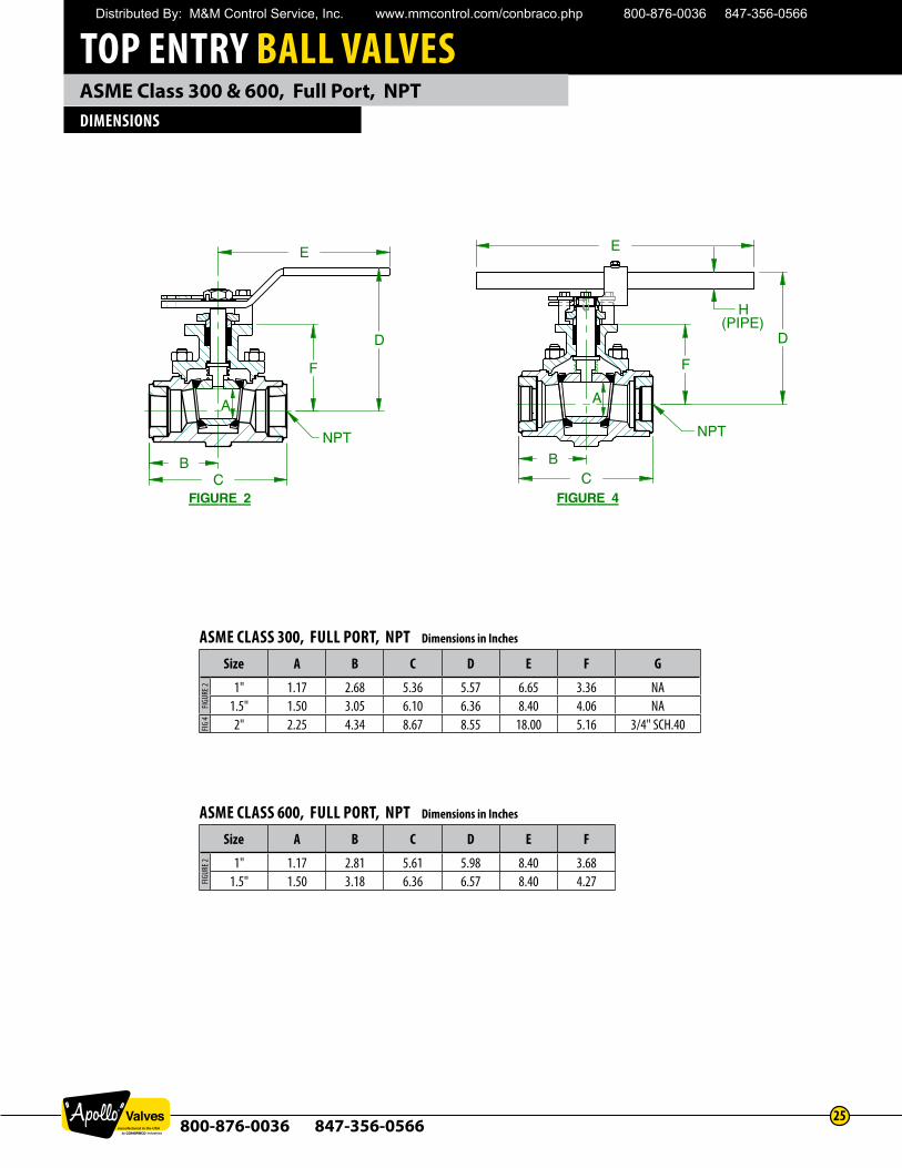
800-876-0036 847-356-056625
ASME Class 300 & 600, Full Port, NPTDIMENSIONS
E
E
B C
F
D
BC
D
F
FIGURE 2
FIGURE 4
H(PIPE)
NPT
NPT
A
A
E
E
BC
F
D
B C
D
F
FIGURE 2
FIGURE 4
H(PIPE)
NPT
NPT
A
A
ASME CLASS 300, FULL PORT, NPT Dimensions in Inches
Size A B C D E F G
1" 1.17 2.68 5.36 5.57 6.65 3.36 NA1.5" 1.50 3.05 6.10 6.36 8.40 4.06 NA2" 2.25 4.34 8.67 8.55 18.00 5.16 3/4" SCH.40
FIGUR
E 2FIG
4
ASME CLASS 600, FULL PORT, NPT Dimensions in Inches
Size A B C D E F
1" 1.17 2.81 5.61 5.98 8.40 3.681.5" 1.50 3.18 6.36 6.57 8.40 4.27FIG
URE 2
Distributed By: M&M Control Service, Inc. www.mmcontrol.com/conbraco.php 800-876-0036 847-356-0566
TOP ENTRY BALL VALVES
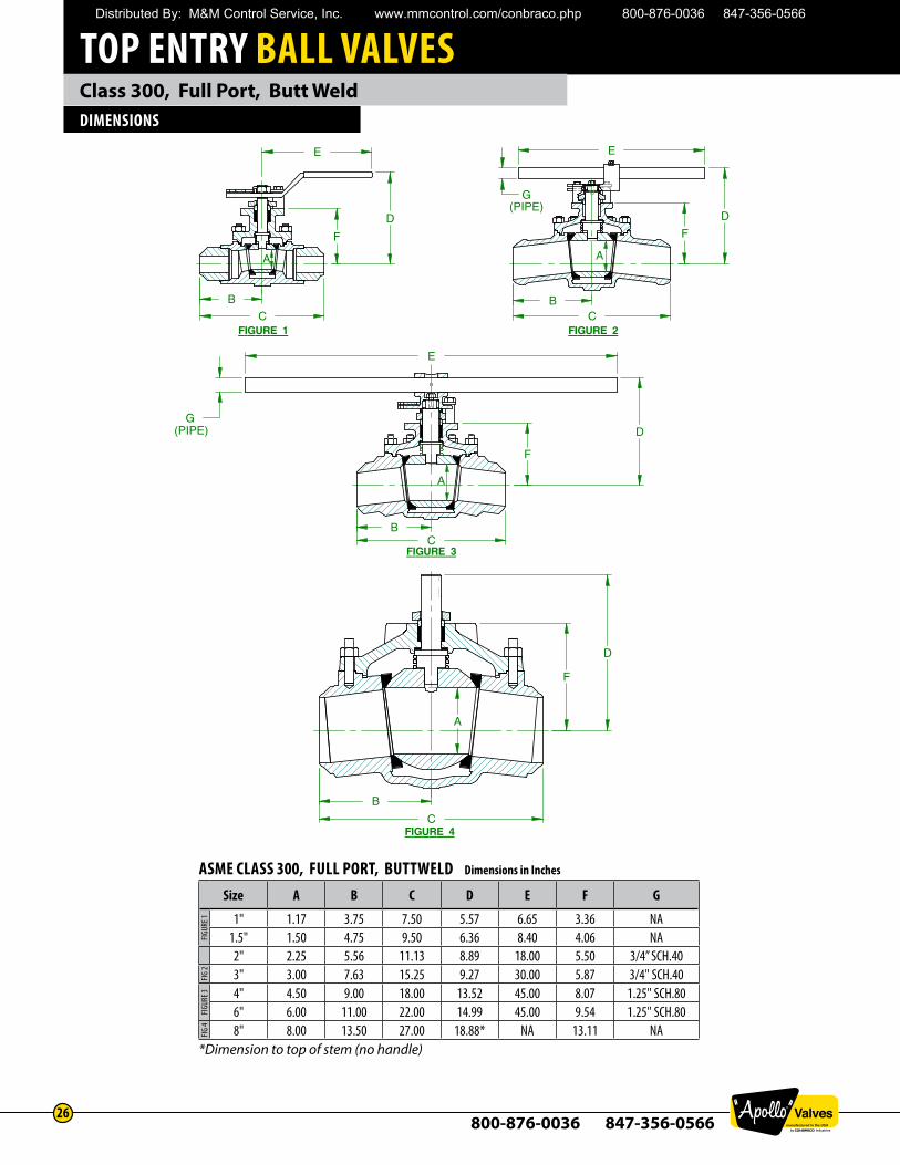
800-876-0036 847-356-056626
Class 300, Full Port, Butt WeldDIMENSIONS
E E
C
B
C B
D
F F
D
G(PIPE)
C
B
A
F
D
E
D
F
G
C B
FIGURE 1 FIGURE 2
FIGURE 3
FIGURE 4
(PIPE)
A A
A
ASME CLASS 300, FULL PORT, BUTTWELD Dimensions in Inches
Size A B C D E F G
1" 1.17 3.75 7.50 5.57 6.65 3.36 NA1.5" 1.50 4.75 9.50 6.36 8.40 4.06 NA2" 2.25 5.56 11.13 8.89 18.00 5.50 3/4” SCH.403" 3.00 7.63 15.25 9.27 30.00 5.87 3/4" SCH.404" 4.50 9.00 18.00 13.52 45.00 8.07 1.25" SCH.806" 6.00 11.00 22.00 14.99 45.00 9.54 1.25" SCH.808" 8.00 13.50 27.00 18.88* NA 13.11 NA
*Dimension to top of stem (no handle)
FIGUR
E 1FIG
2FIG
URE 3
FIG 4
Distributed By: M&M Control Service, Inc. www.mmcontrol.com/conbraco.php 800-876-0036 847-356-0566
TOP ENTRY BALL VALVES
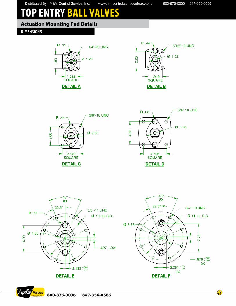
800-876-0036 847-356-056627
Actuation Mounting Pad DetailsDIMENSIONS
1.392SQUARE
DETAIL A DETAIL B
DETAIL C DETAIL D
DETAIL E
1.63 Ø 1.28
R .31
2.25
R .44
Ø 1.62
1.949SQUARE
R .44
Ø 2.50
2.840SQUARE
3.00
4.596SQUARE
4.60
R .62
Ø 3.50
2.133 +.000- .015
.627 ±.001
22.5°
45°8X
6.00
R .81Ø 10.00 B.C.
5/8"-11 UNC
1/4"-20 UNC 5/16"-18 UNC
3/8"-18 UNC
3/4"-10 UNC
Ø 4.50
DETAIL F
22.5°
45°8X
7.75
Ø 11.75 B.C.
3/4"-10 UNC
Ø 6.75
3.261 +.000- .015
2X
.876 +.002- .000
2X
Distributed By: M&M Control Service, Inc. www.mmcontrol.com/conbraco.php 800-876-0036 847-356-0566
TOP ENTRY BALL VALVES
800-876-0036 847-356-056628
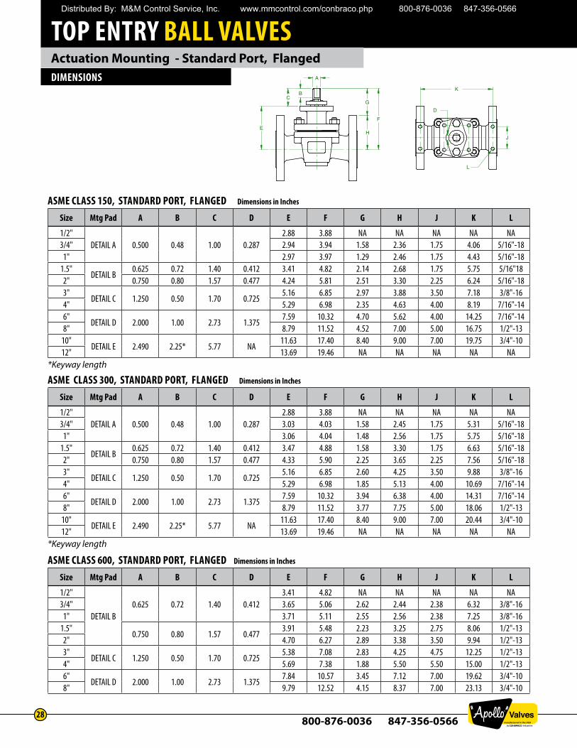
Actuation Mounting - Standard Port, FlangedDIMENSIONS
ASME CLASS 150, STANDARD PORT, FLANGED Dimensions in Inches
Size Mtg Pad A B C D E F G H J K L
1/2"DETAIL A 0.500 0.48 1.00 0.287
2.88 3.88 NA NA NA NA NA3/4" 2.94 3.94 1.58 2.36 1.75 4.06 5/16"-18
1" 2.97 3.97 1.29 2.46 1.75 4.43 5/16"-181.5"
DETAIL B0.625 0.72 1.40 0.412 3.41 4.82 2.14 2.68 1.75 5.75 5/16"18
2" 0.750 0.80 1.57 0.477 4.24 5.81 2.51 3.30 2.25 6.24 5/16"-183"
DETAIL C 1.250 0.50 1.70 0.7255.16 6.85 2.97 3.88 3.50 7.18 3/8"-16
4" 5.29 6.98 2.35 4.63 4.00 8.19 7/16"-146"
DETAIL D 2.000 1.00 2.73 1.3757.59 10.32 4.70 5.62 4.00 14.25 7/16"-14
8" 8.79 11.52 4.52 7.00 5.00 16.75 1/2"-1310"
DETAIL E 2.490 2.25* 5.77 NA11.63 17.40 8.40 9.00 7.00 19.75 3/4"-10
12" 13.69 19.46 NA NA NA NA NA*Keyway length
ASME CLASS 300, STANDARD PORT, FLANGED Dimensions in Inches
Size Mtg Pad A B C D E F G H J K L
1/2"DETAIL A 0.500 0.48 1.00 0.287
2.88 3.88 NA NA NA NA NA3/4" 3.03 4.03 1.58 2.45 1.75 5.31 5/16"-18
1" 3.06 4.04 1.48 2.56 1.75 5.75 5/16"-181.5"
DETAIL B0.625 0.72 1.40 0.412 3.47 4.88 1.58 3.30 1.75 6.63 5/16"-18
2" 0.750 0.80 1.57 0.477 4.33 5.90 2.25 3.65 2.25 7.56 5/16"-183"
DETAIL C 1.250 0.50 1.70 0.7255.16 6.85 2.60 4.25 3.50 9.88 3/8"-16
4" 5.29 6.98 1.85 5.13 4.00 10.69 7/16"-146"
DETAIL D 2.000 1.00 2.73 1.3757.59 10.32 3.94 6.38 4.00 14.31 7/16"-14
8" 8.79 11.52 3.77 7.75 5.00 18.06 1/2"-1310"
DETAIL E 2.490 2.25* 5.77 NA11.63 17.40 8.40 9.00 7.00 20.44 3/4"-10
12" 13.69 19.46 NA NA NA NA NA*Keyway length
ASME CLASS 600, STANDARD PORT, FLANGED Dimensions in Inches
Size Mtg Pad A B C D E F G H J K L
1/2"
DETAIL B0.625 0.72 1.40 0.412
3.41 4.82 NA NA NA NA NA3/4" 3.65 5.06 2.62 2.44 2.38 6.32 3/8"-16
1" 3.71 5.11 2.55 2.56 2.38 7.25 3/8"-161.5"
0.750 0.80 1.57 0.4773.91 5.48 2.23 3.25 2.75 8.06 1/2"-13
2" 4.70 6.27 2.89 3.38 3.50 9.94 1/2"-133"
DETAIL C 1.250 0.50 1.70 0.7255.38 7.08 2.83 4.25 4.75 12.25 1/2"-13
4" 5.69 7.38 1.88 5.50 5.50 15.00 1/2"-136"
DETAIL D 2.000 1.00 2.73 1.3757.84 10.57 3.45 7.12 7.00 19.62 3/4"-10
8" 9.79 12.52 4.15 8.37 7.00 23.13 3/4"-10
K
J
D
A
G
H E
C B
F
L
Distributed By: M&M Control Service, Inc. www.mmcontrol.com/conbraco.php 800-876-0036 847-356-0566
TOP ENTRY BALL VALVES
800-876-0036 847-356-056629
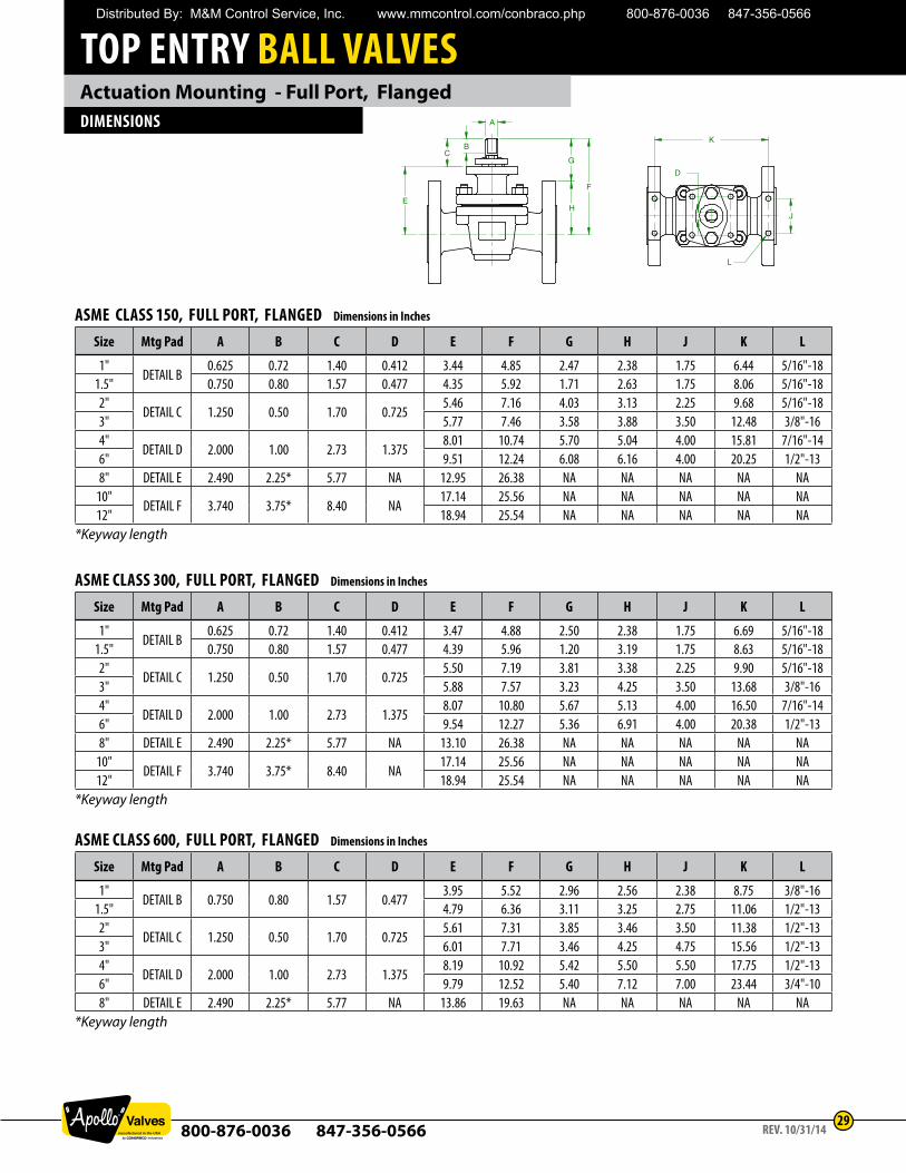
Actuation Mounting - Full Port, FlangedDIMENSIONS
K
J
D
A
G
H E
C B
F
L
ASME CLASS 150, FULL PORT, FLANGED Dimensions in Inches
Size Mtg Pad A B C D E F G H J K L
1"DETAIL B
0.625 0.72 1.40 0.412 3.44 4.85 2.47 2.38 1.75 6.44 5/16"-181.5" 0.750 0.80 1.57 0.477 4.35 5.92 1.71 2.63 1.75 8.06 5/16"-182"
DETAIL C 1.250 0.50 1.70 0.7255.46 7.16 4.03 3.13 2.25 9.68 5/16"-18
3" 5.77 7.46 3.58 3.88 3.50 12.48 3/8"-164"
DETAIL D 2.000 1.00 2.73 1.3758.01 10.74 5.70 5.04 4.00 15.81 7/16"-14
6" 9.51 12.24 6.08 6.16 4.00 20.25 1/2"-138" DETAIL E 2.490 2.25* 5.77 NA 12.95 26.38 NA NA NA NA NA
10"DETAIL F 3.740 3.75* 8.40 NA
17.14 25.56 NA NA NA NA NA12" 18.94 25.54 NA NA NA NA NA
*Keyway length
ASME CLASS 300, FULL PORT, FLANGED Dimensions in Inches
Size Mtg Pad A B C D E F G H J K L
1"DETAIL B
0.625 0.72 1.40 0.412 3.47 4.88 2.50 2.38 1.75 6.69 5/16"-181.5" 0.750 0.80 1.57 0.477 4.39 5.96 1.20 3.19 1.75 8.63 5/16"-182"
DETAIL C 1.250 0.50 1.70 0.7255.50 7.19 3.81 3.38 2.25 9.90 5/16"-18
3" 5.88 7.57 3.23 4.25 3.50 13.68 3/8"-164"
DETAIL D 2.000 1.00 2.73 1.3758.07 10.80 5.67 5.13 4.00 16.50 7/16"-14
6" 9.54 12.27 5.36 6.91 4.00 20.38 1/2"-138" DETAIL E 2.490 2.25* 5.77 NA 13.10 26.38 NA NA NA NA NA
10"DETAIL F 3.740 3.75* 8.40 NA
17.14 25.56 NA NA NA NA NA12" 18.94 25.54 NA NA NA NA NA
*Keyway length
ASME CLASS 600, FULL PORT, FLANGED Dimensions in Inches
Size Mtg Pad A B C D E F G H J K L
1"DETAIL B 0.750 0.80 1.57 0.477
3.95 5.52 2.96 2.56 2.38 8.75 3/8"-161.5" 4.79 6.36 3.11 3.25 2.75 11.06 1/2"-132"
DETAIL C 1.250 0.50 1.70 0.7255.61 7.31 3.85 3.46 3.50 11.38 1/2"-13
3" 6.01 7.71 3.46 4.25 4.75 15.56 1/2"-134"
DETAIL D 2.000 1.00 2.73 1.3758.19 10.92 5.42 5.50 5.50 17.75 1/2"-13
6" 9.79 12.52 5.40 7.12 7.00 23.44 3/4"-108" DETAIL E 2.490 2.25* 5.77 NA 13.86 19.63 NA NA NA NA NA
*Keyway length
REV. 10/31/14
Distributed By: M&M Control Service, Inc. www.mmcontrol.com/conbraco.php 800-876-0036 847-356-0566
TOP ENTRY BALL VALVES
800-876-0036 847-356-056630
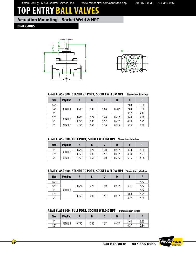
Actuation Mounting - Socket Weld & NPTDIMENSIONS
ASME CLASS 300, STANDARD PORT, SOCKET WELD & NPT Dimensions in Inches
Size Mtg Pad A B C D E F
1/2"DETAIL A 0.500 0.48 1.00 0.287
2.88 3.883/4" 2.88 3.88
1" 3.12 4.121.5"
DETAIL B0.625 0.72 1.40 0.412 3.40 4.80
2" 0.750 0.80 1.57 0.477 4.34 5.913" DETAIL C 1.250 0.50 1.70 0.725 5.16 6.86
ASME CLASS 300, FULL PORT, SOCKET WELD & NPT Dimensions in Inches
Size Mtg Pad A B C D E F
1"DETAIL B
0.625 0.72 1.40 0.412 3.40 4.801.5" 0.750 0.80 1.57 0.477 4.34 5.912" DETAIL C 1.250 0.50 1.70 0.725 5.16 6.86
ASME CLASS 600, STANDARD PORT, SOCKET WELD & NPT Dimensions in Inches
Size Mtg Pad A B C D E F
1/2"
DETAIL B0.625 0.72 1.40 0.412 3.41
4.823/4" 4.82
1" 4.821.5"
0.750 0.80 1.57 0.4773.68 5.25
2" 4.27 5.84
ASME CLASS 600, FULL PORT, SOCKET WELD & NPT Dimensions in Inches
Size Mtg Pad A B C D E F
1"DETAIL B 0.750 0.80 1.57 0.477
3.68 5.251.5" 4.27 5.84
A
B C
E
F
D
Distributed By: M&M Control Service, Inc. www.mmcontrol.com/conbraco.php 800-876-0036 847-356-0566
TOP ENTRY BALL VALVES
800-876-0036 847-356-056631
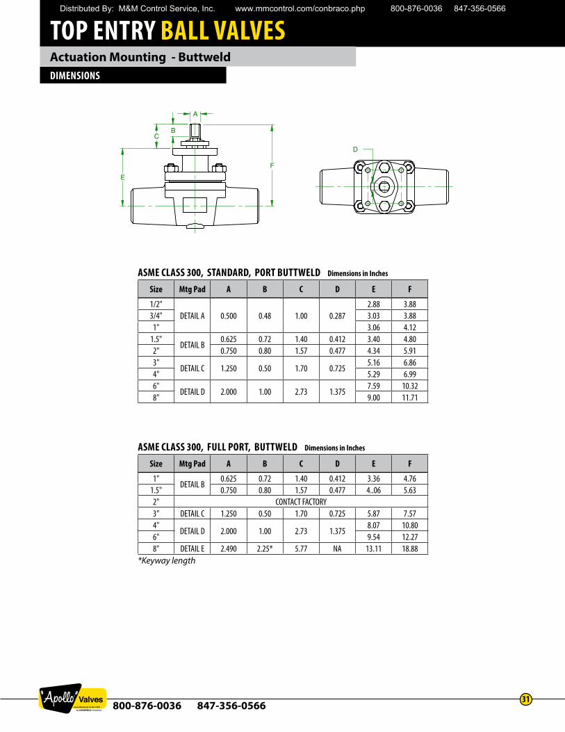
Actuation Mounting - ButtweldDIMENSIONS
ASME CLASS 300, STANDARD, PORT BUTTWELD Dimensions in Inches
Size Mtg Pad A B C D E F
1/2"DETAIL A 0.500 0.48 1.00 0.287
2.88 3.883/4" 3.03 3.88
1" 3.06 4.121.5"
DETAIL B0.625 0.72 1.40 0.412 3.40 4.80
2" 0.750 0.80 1.57 0.477 4.34 5.913"
DETAIL C 1.250 0.50 1.70 0.7255.16 6.86
4" 5.29 6.996"
DETAIL D 2.000 1.00 2.73 1.3757.59 10.32
8" 9.00 11.71
A
C B
E
F
D
ASME CLASS 300, FULL PORT, BUTTWELD Dimensions in Inches
Size Mtg Pad A B C D E F
1"DETAIL B
0.625 0.72 1.40 0.412 3.36 4.761.5" 0.750 0.80 1.57 0.477 4..06 5.632" CONTACT FACTORY3" DETAIL C 1.250 0.50 1.70 0.725 5.87 7.574"
DETAIL D 2.000 1.00 2.73 1.3758.07 10.80
6" 9.54 12.278" DETAIL E 2.490 2.25* 5.77 NA 13.11 18.88
*Keyway length
Distributed By: M&M Control Service, Inc. www.mmcontrol.com/conbraco.php 800-876-0036 847-356-0566
TOP ENTRY BALL VALVES
800-876-0036 847-356-056632
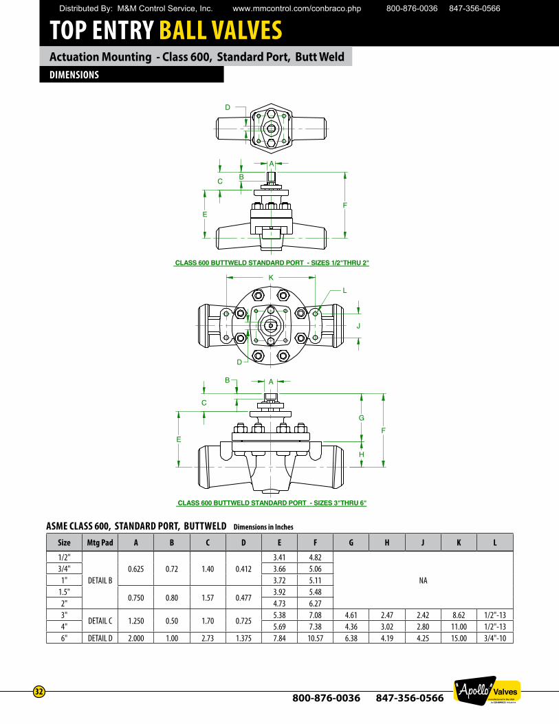
Actuation Mounting - Class 600, Standard Port, Butt WeldDIMENSIONS
ASME CLASS 600, STANDARD PORT, BUTTWELD Dimensions in Inches
Size Mtg Pad A B C D E F G H J K L
1/2"
DETAIL B0.625 0.72 1.40 0.412
3.41 4.82
NA3/4" 3.66 5.06
1" 3.72 5.111.5"
0.750 0.80 1.57 0.4773.92 5.48
2" 4.73 6.273"
DETAIL C 1.250 0.50 1.70 0.7255.38 7.08 4.61 2.47 2.42 8.62 1/2"-13
4" 5.69 7.38 4.36 3.02 2.80 11.00 1/2"-136" DETAIL D 2.000 1.00 2.73 1.375 7.84 10.57 6.38 4.19 4.25 15.00 3/4"-10
CLASS 600 BUTTWELD STANDARD PORT - SIZES 1/2"THRU 2"
CLASS 600 BUTTWELD STANDARD PORT - SIZES 3"THRU 6"
D
E F
C B
A
K
J
L
E F
C
AB
D
H
G
Distributed By: M&M Control Service, Inc. www.mmcontrol.com/conbraco.php 800-876-0036 847-356-0566
TOP ENTRY BALL VALVES
800-876-0036 847-356-056633
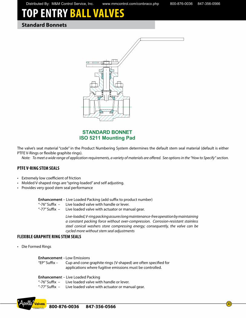
Standard Bonnets
The valve’s seat material “code” in the Product Numbering System determines the default stem seal material (default is either PTFE V-Rings or flexible graphite rings).
Note: To meet a wide range of application requirements, a variety of materials are offered. See options in the “How to Specify” section.
PTFE V-RING STEM SEALS
• Extremely low coefficient of friction• Molded V-shaped rings are “spring-loaded” and self adjusting.• Provides very good stem seal performance
FLEXIBLE GRAPHITE RING STEM SEALS
• Die Formed Rings
STANDARD BONNETISO 5211 Mounting Pad
Enhancement – Live Loaded Packing (add suffix to product number)“-76” Suffix – Live loaded valve with handle or lever. ”-77” Suffix – Live loaded valve with actuator or manual gear.
Live-loaded, V-ring packing assures long maintenance-free operation by maintaining a constant packing force without over-compression. Corrosion-resistant stainless steel conical washers store compressing energy; consequently, the valve can be cycled more without stem seal adjustments
Enhancement – Low Emissions“EP” Suffix – Cup and cone graphite rings (V-shaped) are often specified for
applications where fugitive emissions must be controlled.
Enhancement – Live Loaded Packing“-76” Suffix – Live loaded valve with handle or lever. ”-77” Suffix – Live loaded valve with actuator or manual gear.
Distributed By: M&M Control Service, Inc. www.mmcontrol.com/conbraco.php 800-876-0036 847-356-0566
TOP ENTRY BALL VALVES
800-876-0036 847-356-056634
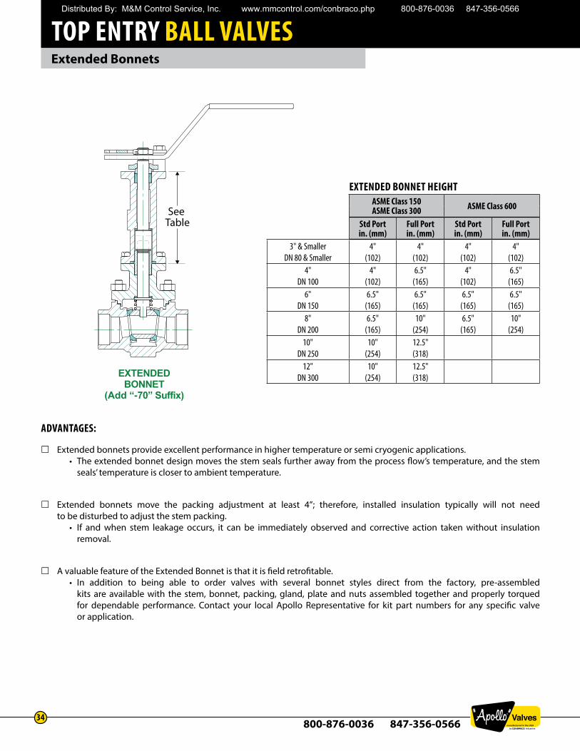
Extended Bonnets
ADVANTAGES:
£Extended bonnets provide excellent performance in higher temperature or semi cryogenic applications.• The extended bonnet design moves the stem seals further away from the process flow’s temperature, and the stem
seals’ temperature is closer to ambient temperature.
£Extended bonnets move the packing adjustment at least 4”; therefore, installed insulation typically will not need to be disturbed to adjust the stem packing.
• If and when stem leakage occurs, it can be immediately observed and corrective action taken without insulationremoval.
£A valuable feature of the Extended Bonnet is that it is field retrofitable.• In addition to being able to order valves with several bonnet styles direct from the factory, pre-assembled
kits are available with the stem, bonnet, packing, gland, plate and nuts assembled together and properly torquedfor dependable performance. Contact your local Apollo Representative for kit part numbers for any specific valveor application.
EXTENDEDBONNET
(Add “-70” Suffix)
See Table
EXTENDED BONNET HEIGHTASME Class 150ASME Class 300 ASME Class 600
Std Portin. (mm)
Full Portin. (mm)
Std Portin. (mm)
Full Portin. (mm)
3" & SmallerDN 80 & Smaller
4"(102)
4"(102)
4"(102)
4"(102)
4"DN 100
4"(102)
6.5"(165)
4"(102)
6.5"(165)
6"DN 150
6.5"(165)
6.5"(165)
6.5"(165)
6.5"(165)
8"DN 200
6.5"(165)
10"(254)
6.5"(165)
10"(254)
10"DN 250
10"(254)
12.5"(318)
12"DN 300
10"(254)
12.5"(318)
Distributed By: M&M Control Service, Inc. www.mmcontrol.com/conbraco.php 800-876-0036 847-356-0566
TOP ENTRY BALL VALVES
800-876-0036 847-356-056635
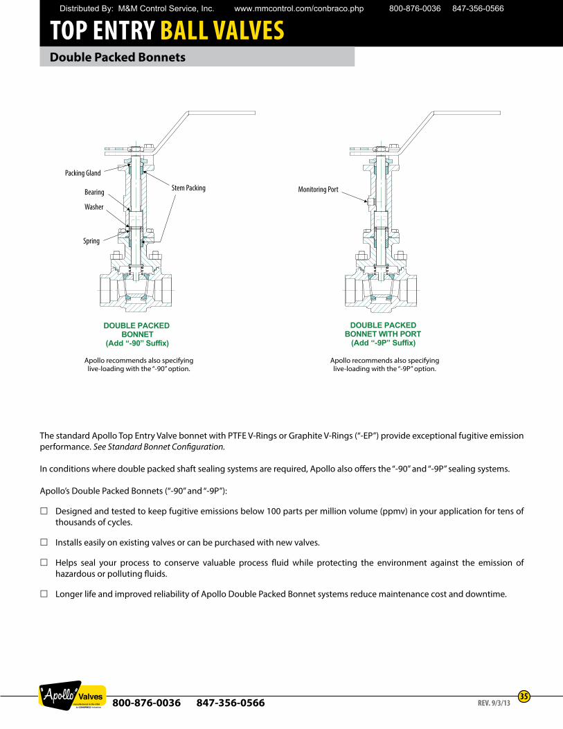
Double Packed Bonnets
DOUBLE PACKED BONNET
(Add “-90” Suffix)
DOUBLE PACKEDBONNET WITH PORT
(Add “-9P” Suffix)
Stem Packing
Packing Gland
Bearing
Washer
Spring
Monitoring Port
The standard Apollo Top Entry Valve bonnet with PTFE V-Rings or Graphite V-Rings (“-EP”) provide exceptional fugitive emission performance. See Standard Bonnet Configuration.
In conditions where double packed shaft sealing systems are required, Apollo also offers the “-90” and “-9P” sealing systems.
Apollo’s Double Packed Bonnets (“-90” and “-9P”):
£ Designed and tested to keep fugitive emissions below 100 parts per million volume (ppmv) in your application for tens of thousands of cycles.
£ Installs easily on existing valves or can be purchased with new valves.
£ Helps seal your process to conserve valuable process fluid while protecting the environment against the emission of hazardous or polluting fluids.
£ Longer life and improved reliability of Apollo Double Packed Bonnet systems reduce maintenance cost and downtime.
Apollo recommends also specifying live-loading with the “-90” option.
Apollo recommends also specifying live-loading with the “-9P” option.
REV. 9/3/13
Distributed By: M&M Control Service, Inc. www.mmcontrol.com/conbraco.php 800-876-0036 847-356-0566
TOP ENTRY BALL VALVES
800-876-0036 847-356-056636
Steam Jacketed Top Entry Valves
Conbraco’s Apollo® Top Entry Ball Valves are ideally suited for jacketed applications. The top entry concept allows for continued access to stem packings and valve internals for ease of maintenance without disturbing the jacket itself or removing the valve from the pipeline.
Partial jacketing may be used on standard valves. Partial jacketing is applied just to the center section of the valve and does not incorporate the neck area or flanges of the valve. It is generally specified to allow the use of standard flanges and retain conventional flange bolting.
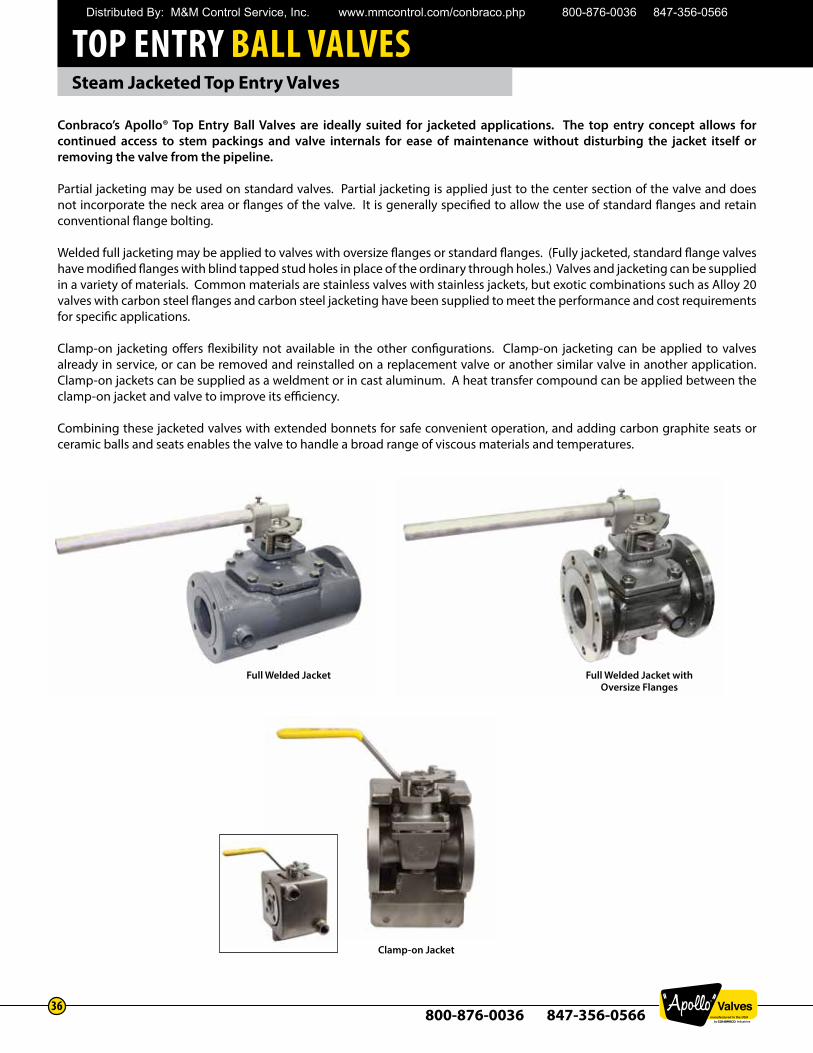
Welded full jacketing may be applied to valves with oversize flanges or standard flanges. (Fully jacketed, standard flange valves have modified flanges with blind tapped stud holes in place of the ordinary through holes.) Valves and jacketing can be supplied in a variety of materials. Common materials are stainless valves with stainless jackets, but exotic combinations such as Alloy 20 valves with carbon steel flanges and carbon steel jacketing have been supplied to meet the performance and cost requirements for specific applications.
Clamp-on jacketing offers flexibility not available in the other configurations. Clamp-on jacketing can be applied to valves already in service, or can be removed and reinstalled on a replacement valve or another similar valve in another application. Clamp-on jackets can be supplied as a weldment or in cast aluminum. A heat transfer compound can be applied between the clamp-on jacket and valve to improve its efficiency.
Combining these jacketed valves with extended bonnets for safe convenient operation, and adding carbon graphite seats or ceramic balls and seats enables the valve to handle a broad range of viscous materials and temperatures.
Full Welded Jacket Full Welded Jacket with Oversize Flanges
Clamp-on Jacket
Distributed By: M&M Control Service, Inc. www.mmcontrol.com/conbraco.php 800-876-0036 847-356-0566
TOP ENTRY BALL VALVES
800-876-0036 847-356-056637
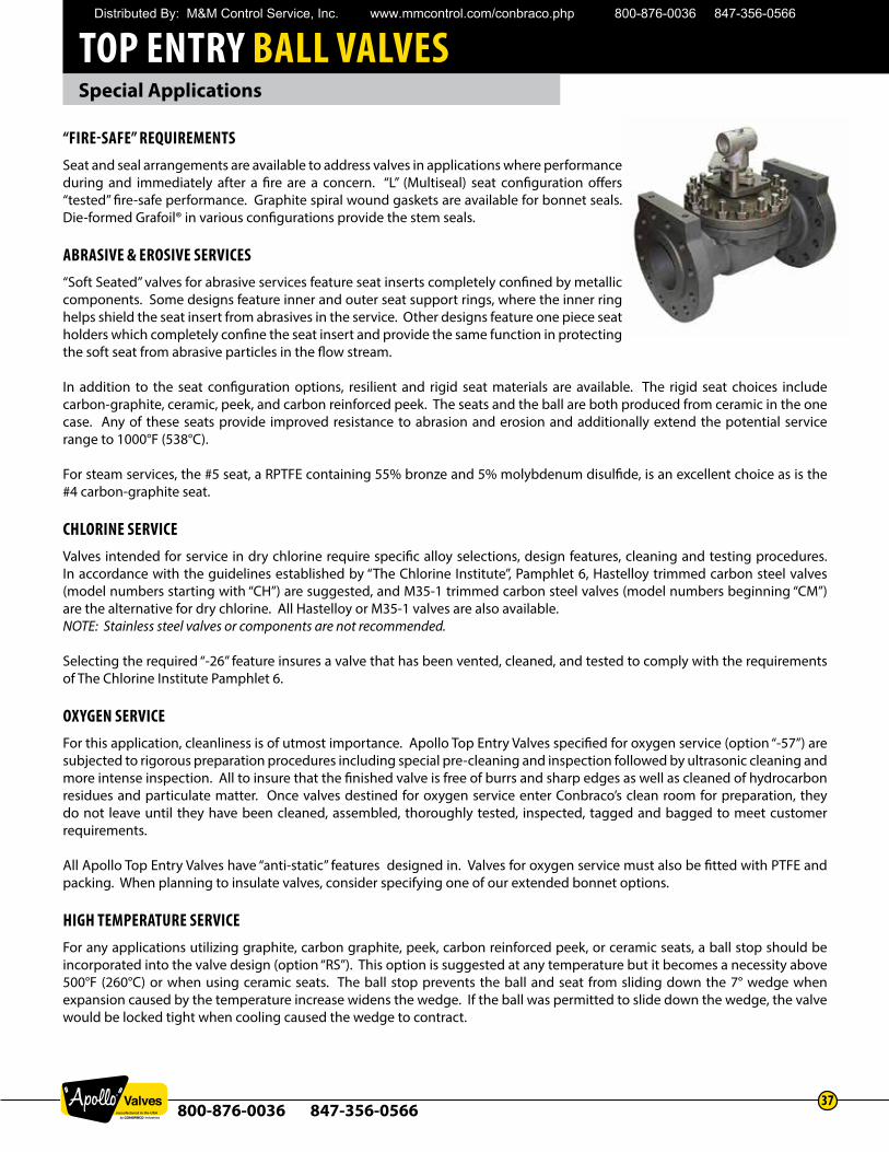
“FIRE-SAFE” REQUIREMENTSSeat and seal arrangements are available to address valves in applications where performance during and immediately after a fire are a concern. “L” (Multiseal) seat configuration offers “tested” fire-safe performance. Graphite spiral wound gaskets are available for bonnet seals. Die-formed Grafoil® in various configurations provide the stem seals.
ABRASIVE & EROSIVE SERVICES“Soft Seated” valves for abrasive services feature seat inserts completely confined by metallic components. Some designs feature inner and outer seat support rings, where the inner ring helps shield the seat insert from abrasives in the service. Other designs feature one piece seat holders which completely confine the seat insert and provide the same function in protecting the soft seat from abrasive particles in the flow stream.
In addition to the seat configuration options, resilient and rigid seat materials are available. The rigid seat choices include carbon-graphite, ceramic, peek, and carbon reinforced peek. The seats and the ball are both produced from ceramic in the one case. Any of these seats provide improved resistance to abrasion and erosion and additionally extend the potential service range to 1000°F (538°C).
For steam services, the #5 seat, a RPTFE containing 55% bronze and 5% molybdenum disulfide, is an excellent choice as is the #4 carbon-graphite seat.
CHLORINE SERVICEValves intended for service in dry chlorine require specific alloy selections, design features, cleaning and testing procedures. In accordance with the guidelines established by “The Chlorine Institute”, Pamphlet 6, Hastelloy trimmed carbon steel valves (model numbers starting with “CH”) are suggested, and M35-1 trimmed carbon steel valves (model numbers beginning “CM”) are the alternative for dry chlorine. All Hastelloy or M35-1 valves are also available. NOTE: Stainless steel valves or components are not recommended.
Selecting the required “-26” feature insures a valve that has been vented, cleaned, and tested to comply with the requirements of The Chlorine Institute Pamphlet 6.
OXYGEN SERVICEFor this application, cleanliness is of utmost importance. Apollo Top Entry Valves specified for oxygen service (option “-57”) are subjected to rigorous preparation procedures including special pre-cleaning and inspection followed by ultrasonic cleaning and more intense inspection. All to insure that the finished valve is free of burrs and sharp edges as well as cleaned of hydrocarbon residues and particulate matter. Once valves destined for oxygen service enter Conbraco’s clean room for preparation, they do not leave until they have been cleaned, assembled, thoroughly tested, inspected, tagged and bagged to meet customer requirements.
All Apollo Top Entry Valves have “anti-static” features designed in. Valves for oxygen service must also be fitted with PTFE and packing. When planning to insulate valves, consider specifying one of our extended bonnet options.
HIGH TEMPERATURE SERVICEFor any applications utilizing graphite, carbon graphite, peek, carbon reinforced peek, or ceramic seats, a ball stop should be incorporated into the valve design (option “RS”). This option is suggested at any temperature but it becomes a necessity above 500°F (260°C) or when using ceramic seats. The ball stop prevents the ball and seat from sliding down the 7° wedge when expansion caused by the temperature increase widens the wedge. If the ball was permitted to slide down the wedge, the valve would be locked tight when cooling caused the wedge to contract.
Special Applications
Distributed By: M&M Control Service, Inc. www.mmcontrol.com/conbraco.php 800-876-0036 847-356-0566
TOP ENTRY BALL VALVES
800-876-0036 847-356-056638
Flow Coefficients
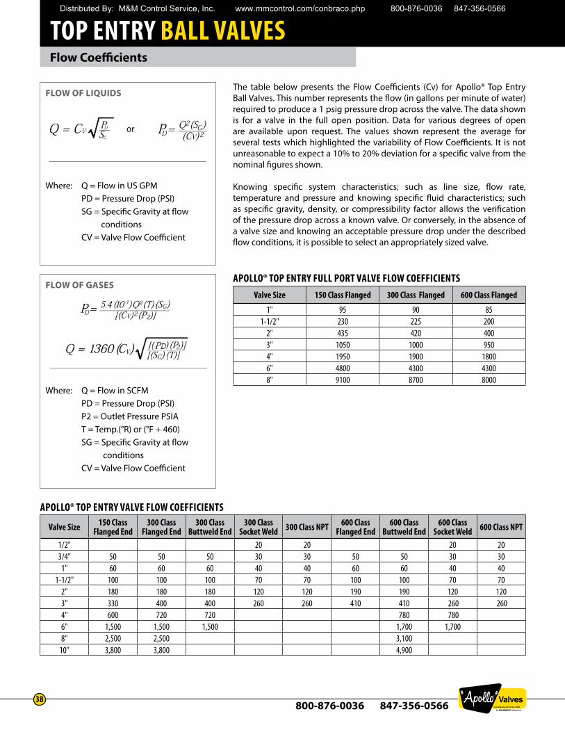
The table below presents the Flow Coefficients (Cv) for Apollo® Top Entry Ball Valves. This number represents the flow (in gallons per minute of water) required to produce a 1 psig pressure drop across the valve. The data shown is for a valve in the full open position. Data for various degrees of open are available upon request. The values shown represent the average for several tests which highlighted the variability of Flow Coefficients. It is not unreasonable to expect a 10% to 20% deviation for a specific valve from the nominal figures shown.
Knowing specific system characteristics; such as line size, flow rate, temperature and pressure and knowing specific fluid characteristics; such as specific gravity, density, or compressibility factor allows the verification of the pressure drop across a known valve. Or conversely, in the absence of a valve size and knowing an acceptable pressure drop under the described flow conditions, it is possible to select an appropriately sized valve.
APOLLO® TOP ENTRY FULL PORT VALVE FLOW COEFFICIENTSValve Size 150 Class Flanged 300 Class Flanged 600 Class Flanged
1" 95 90 851-1/2" 230 225 200
2" 435 420 4003" 1050 1000 9504" 1950 1900 18006" 4800 4300 43008" 9100 8700 8000
APOLLO® TOP ENTRY VALVE FLOW COEFFICIENTS
Valve Size 150 Class Flanged End
300 Class Flanged End
300 Class Buttweld End
300 Class Socket Weld 300 Class NPT 600 Class
Flanged End600 Class
Buttweld End600 Class
Socket Weld 600 Class NPT
1/2" 20 20 20 203/4" 50 50 50 30 30 50 50 30 30
1" 60 60 60 40 40 60 60 40 40 1-1/2" 100 100 100 70 70 100 100 70 70
2" 180 180 180 120 120 190 190 120 1203" 330 400 400 260 260 410 410 260 2604" 600 720 720 780 7806" 1,500 1,500 1,500 1,700 1,7008" 2,500 2,500 3,100
10" 3,800 3,800 4,900
FLOW OF GASES
Where: Q = Flow in SCFMPD = Pressure Drop (PSI)P2 = Outlet Pressure PSIAT = Temp.(°R) or (°F + 460)SG = Specific Gravity at flow conditionsCV = Valve Flow Coefficient
FLOW OF LIQUIDS
Where: Q = Flow in US GPMPD = Pressure Drop (PSI)SG = Specific Gravity at flow conditionsCV = Valve Flow Coefficient
or
Distributed By: M&M Control Service, Inc. www.mmcontrol.com/conbraco.php 800-876-0036 847-356-0566
TOP ENTRY BALL VALVES
800-876-0036 847-356-056639
Operating Torque
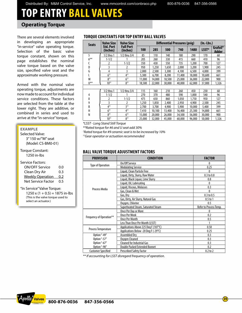
There are several elements involved in developing an appropriate “in-service” valve operating torque. Selection of the basic valve torque constant, shown on this page establishes the nominal valve torque based on the valve size, specified valve seat and the approximate working pressure.
Armed with the nominal valve operating torque, adjustments are now made to account for individual service conditions. These factors are selected from the table at the lower right. They are additive, or combined in series and used to arrive at the “in-service” torque.
BALL VALVE TORQUE ADJUSTMENT FACTORSPROVISION CONDITION FACTOR
Type of Operation On/Off Service 0Modulating Service 0.25
Process Media
Liquid, Clean Particle Free 0Liquid, Dirty, Slurry, Raw Water 0.3 to 0.8Liquid, Black Liquor, Lime Slurry 0.8Liquid, Oil, Lubricating 0Liquid, Viscous, Molasses 0.3Gas, Clean & Wet 0Gas, Dry 0.3 to 0.5Gas, Dirty, Air Slurry, Natural Gas 0.5 to 1Oxygen, Chlorine 0.5Superheated Steam, Saturated Steam Refer to Process Temp.
Frequency of Operation**
Once Per Day or More 0Once Per Week 0.2Once Per Month 0.5Less Than Once Per Month (LSST) 1
Process Temperature Applications Above 225 Deg F (107°C) 0.50Applications Below -20 Deg F (-29°C) 0.25
Option “-49”Option “-57”Option “-67”Option “-90”
Assembled Dry 0.3Oxygen Cleaned 0.3Cleaned for Industrial Gas 0.3Double Packed Extended Bonnet 0.2
Customer Specified Prescribed Safety Factor 0.2 to 2** If accounting for LSST disregard frequency of operation.
TORQUE CONSTANTS FOR TOP ENTRY BALL VALVES
Seats Valve SizeStd. Port(Inches)
Valve SizeFull Port(Inches)
Differential Pressures (psig) (In.-Lbs.)
100 285 500 740 1480 LSST* Grafoil®Adder
5 1/2 thru 1 1/2 thru 3/4 85 110 140 180 290 170 686** 1-1/2 1 205 260 330 415 660 410 96C 2 1-1/2 350 430 550 735 1,200 700 127D 3 2 950 1,250 1,650 2,000 3,200 1,900 245G 4 3 2,000 2,500 3,300 4,100 6,500 4,000 399L 6†† 4†† 5,300 6,700 8,200 11,400 18,000 10,600 661M 8†† 6†† 11,000 14,000 18,500 25,000 36,000 22,000 900U** 10†† 8†† 18,500 22,000 30,000 40,000 62,000 37,000 1,326
1/2 thru 1 1/2 thru 3/4 115 160 210 260 450 230 684 1-1/2 1 270 370 480 590 1,000 540 968 2 1-1/2 475 650 860 1,050 1,750 950 1279 3 2 1,250 1,850 2,400 2,950 4,900 2,500 245B 4†† 3†† 2,700 3,700 4,900 5,900 10,000 5,400 399H 6†† 4†† 7,410 10,100 13,400 16,400 25,300 14,800 661N 8†† 6†† 15,000 20,000 26,000 34,500 56,000 30,000 900
10†† 8†† 25,000 32,000 45,000 60,000 96,000 50,000 1,326*LSST - Long Stand Still Torque**Rated torque for #6 and U seat add 30%†Rated torque for #9 ceramic seat is to be increased by 10%††Gear operator or actuation recommended
EXAMPLESelected Valve:
3” 150 w/”M” seat(Model: CS-BM0-01)
Torque Constant: 1250 in-lbs
Service Factors: ON/OFF Service 0.0
Clean Dry Air 0.3 Weekly Operation 0.2
Net Service Factor 0.5
“In Service” Valve Torque: 1250 x (1 + 0.5) = 1875 in-lbs(This is the valve torque used to select an actuator.)
Distributed By: M&M Control Service, Inc. www.mmcontrol.com/conbraco.php 800-876-0036 847-356-0566
TOP ENTRY BALL VALVES
800-876-0036 847-356-056640
How to Specify Apollo Top Entry Ball Valves
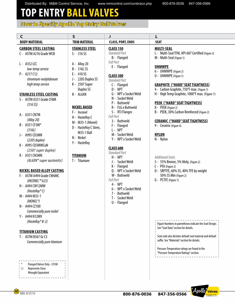
CARBON STEEL CASTINGC - ASTM A216 Grade WCB
L - A352 LCC low-temp service P - A217 C12
chromium-molybdenum high temp service
STAINLESS STEEL CASTING S - ASTM A351 Grade CF8M
(316 SS)
A - A351 CN7M (Alloy 20)
B - A351 CF3M* (316L) J - A995 CD3MN
(2205 duplex) K - A995 CD3MWCuN (2507 super duplex) R - A351 CN3MN
(AL6XN® super austenitic)
NICKEL BASED ALLOY CASTINGF - ASTM A494 Grade CW6MC (INCONEL™ 625) H - A494 CW12MW (Hastelloy® C)M - A494 M35-1 (MONEL®) N - A494 CZ100
Commercially pure nickel Y - A494 N12MV
(Hastelloy® B-2)
TITANIUM CASTINGT - ASTM B367 Gr C3
Commercially pure titanium
MULTI-SEALL - Multi-Seal TFM, API-607 Certified (Figure 3)M - Multi-Seal (Figure 1)
UHMWPE6 - UHMWPE (Figure 2)U - UHMWPE (Figure 1)
GRAPHITE (“HARD” SEAT TIGHTNESS)4 - Carbon Graphite, 750°F max. (Figure 1) H - High Temp Graphite, 1000°F max. (Figure 1)
PEEK (“HARD” SEAT TIGHTNESS)8 - PEEK (Figure 2) B - PEEK, 30% Carbon Reinforced (Figure 2)
CERAMIC (“HARD” SEAT TIGHTNESS)9 - Ceramic (Figure 4)
NYLONN - Nylon
Additional Seats 5 - 55% Bronze, 5% Moly, (Figure 2)C - PFA (Figure 2) D - SRPTFE, 60% SS, 40% TFE by weight 50% SS Min (Figure 2)G - PCTFE (Figure 1)
STAINLESS STEELS - 316 SS
A - Alloy 20B - 316L SSE - 410 SSJ - 220S Duplex SSK - 2507 Super Duplex SSR - AL6XN
NICKEL BASEDF - InconelH - Hastelloy CM - M35-1 (Monel)D - Hastelloy C Stem, M35-1 BallN - NickelY - Hastelloy
TITANIUMT - Titanium
CLASS 150Standard Port
B - FlangedFull Port
E - Flanged
CLASS 300Standard Port
C - FlangedD - NPTG - NPT x Socket WeldN - Socket WeldP - ButtweldR - FLG x ButtweldS - RTJ Flanges
Full Port3 - ButtweldF - FlangedL - NPTM - Socket WeldY - NPT x Socket Weld
CLASS 600Standard Port
H - NPTJ - Socket WeldK - FlangedQ - NPT x Socket WeldW - Buttweld
Full Port4 - NPT6 - NPT x Socket Weld7 - ButtweldT - Socket WeldU - Flanged
Figure Numbers in parentheses indicate the Seat Design.See “Seat Data” section for details.
Seat code also dictates default seal material and default suffix. See “Materials” section for details.
Pressure-Temperature ratings are found in the “Pressure-Temperature Ratings” section.
* Flanged Valves Only - CF3M( ) Represents Close
Wrought Equivalent
REV. 9/17/13
C S J L 4 24 BODY MATERIAL TRIM MATERIAL CLASS, PORT, ENDS SEAT SIZE (IN) OPTIONS
Distributed By: M&M Control Service, Inc. www.mmcontrol.com/conbraco.php 800-876-0036 847-356-0566
TOP ENTRY BALL VALVES
800-876-0036 847-356-056641
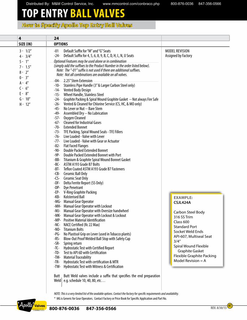
3 - 1/2”4 - 3/4”5 - 1”7 - 1.5”8 - 2”0 - 3”A - 4”C - 6” E - 8” G - 10” H - 12”
EXAMPLE:CSJL424A
Carbon Steel Body316 SS TrimClass 600Standard PortSocket Weld EndsAPI-607, Multiseal Seat3/4”Spiral Wound Flexible Graphite GasketFlexible Graphite PackingModel Revision = A
MODEL REVISIONAssigned by Factory
-01 Default Suffix for “M” and “G” Seats-24- Default Suffix for 4, 5, 6, 8, 9, B, C, D, H, L, N, U SeatsOptional Features may be used alone or in combination (simply add the suffixes to the Product Number in the order listed below). Note: The “-01” suffix is not used if there are additional suffixes. Note: Not all combinations are available on all valves.-04- 2.25” Stem Extension-10- Stainless Pipe Handle (3” & Larger Carbon Steel only)-14- Vented Body Design-15- Wheel Handle, Stainless Steel-24- Graphite Packing & Spiral Wound Graphite Gasket -- Not always Fire Safe-26- Vented & Cleaned for Chlorine Service (CS, HC, & MO only)-45- No Lever or Nut -- Bare Stem-49- Assembled Dry -- No Lubrication-57- Oxygen Cleaned-67- Cleaned for Industrial Gases-70- Extended Bonnet-73- TFE Packing, Spiral Wound Seals - TFE Fillers-76- Live Loaded - Valve with Lever-77- Live Loaded - Valve with Gear or Actuator-82- Flat Faced Flanges-90- Double Packed Extended Bonnet-9P- Double Packed Extended Bonnet with Port-BB- Titanium & Graphite Spiral Wound Bonnet Gasket-BC- ASTM A193 Grade B7 Bolts-BT- Teflon Coated ASTM A193 Grade B7 Fasteners-CB- Ceramic Ball Only-CS- Ceramic Seat Only-DF- Delta Ferrite Report (SS Only)-DP- Dye Penetrant-EP- V-Ring Graphite Packing-KB- Kolsterised Ball-MG- Manual Gear Operator-MH- Manual Gear Operator with Lockout-MJ- Manual Gear Operator with Oversize handwheel-MK- Manual Gear Operator with Lockout & Lockout-MP- Positive Material Identification-NC- NACE Certified (Rc 22 Max)-NO- Titanium Bolts-PG- No Plastisol Grip on Lever (used in Tobacco plants)-RS- Blow-Out Proof Welded Ball Stop with Safety Cap-SR- Spring return-TC- Hydrostatic Test with Certified Report-TD- Test to API 6D with Certification-TM- Material Traceability-TR- Hydrostatic Test with certification & MTR-TW- Hydrostatic Test with Witness & Certification
Butt Butt Weld valves include a suffix that specifies the end preparation Weld e.g. schedule 10, 40, 80, etc…
NOTE: This is a very limited list of the available options. Contact the factory for specific requirements and availability. * MG is Generic for Gear Operators. Contact Factory or Price Book for Specific Application and Part No.
How to Specify Apollo Top Entry Ball Valves
REV. 8/30/13
C S J L 4 24BODY MATERIAL TRIM MATERIAL CLASS, PORT, ENDS SEAT SIZE (IN) OPTIONS
Distributed By: M&M Control Service, Inc. www.mmcontrol.com/conbraco.php 800-876-0036 847-356-0566
TOP ENTRY BALL VALVES
800-876-0036 847-356-056642
REV. 7/21/14
How to Specify Apollo Top Entry Repair Kits
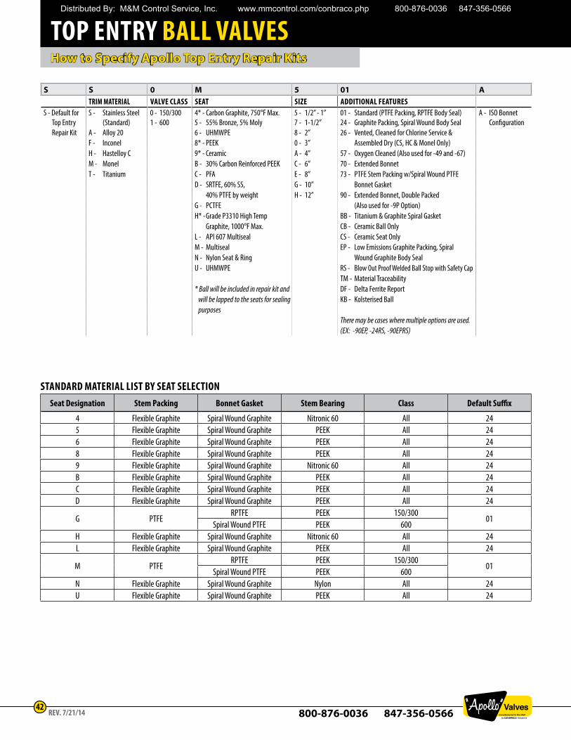
S S 0 M 5 01 ATRIM MATERIAL VALVE CLASS SEAT SIZE ADDITIONAL FEATURES
S - Default for S - Stainless Steel 0 - 150/300 4* - Carbon Graphite, 750°F Max. 5 - 1/2” - 1” 01 - Standard (PTFE Packing, RPTFE Body Seal) A - ISO BonnetTop Entry (Standard) 1 - 600 5 - 55% Bronze, 5% Moly 7 - 1-1/2” 24 - Graphite Packing, Spiral Wound Body Seal ConfigurationRepair Kit A - Alloy 20 6 - UHMWPE 8 - 2” 26 - Vented, Cleaned for Chlorine Service &
F - Inconel 8* - PEEK 0 - 3” Assembled Dry (CS, HC & Monel Only)H - Hastelloy C 9* - Ceramic A - 4” 57 - Oxygen Cleaned (Also used for -49 and -67)M - Monel B - 30% Carbon Reinforced PEEK C - 6” 70 - Extended BonnetT - Titanium C - PFA E - 8” 73 - PTFE Stem Packing w/Spiral Wound PTFE
D - SRTFE, 60% SS, G - 10” Bonnet Gasket 40% PTFE by weight H - 12” 90 - Extended Bonnet, Double PackedG - PCTFE (Also used for -9P Option)H* - Grade P3310 High Temp BB - Titanium & Graphite Spiral Gasket Graphite, 1000°F Max. CB - Ceramic Ball OnlyL - API 607 Multiseal CS - Ceramic Seat OnlyM - Multiseal EP - Low Emissions Graphite Packing, SpiralN - Nylon Seat & Ring Wound Graphite Body SealU - UHMWPE RS - Blow Out Proof Welded Ball Stop with Safety Cap
TM - Material Traceability* Ball will be included in repair kit and DF - Delta Ferrite Report
will be lapped to the seats for sealing KB - Kolsterised Ballpurposes
There may be cases where multiple options are used.(EX: -90EP, -24RS, -90EPRS)
STANDARD MATERIAL LIST BY SEAT SELECTIONSeat Designation Stem Packing Bonnet Gasket Stem Bearing Class Default Suffix
4 Flexible Graphite Spiral Wound Graphite Nitronic 60 All 245 Flexible Graphite Spiral Wound Graphite PEEK All 246 Flexible Graphite Spiral Wound Graphite PEEK All 248 Flexible Graphite Spiral Wound Graphite PEEK All 249 Flexible Graphite Spiral Wound Graphite Nitronic 60 All 24B Flexible Graphite Spiral Wound Graphite PEEK All 24C Flexible Graphite Spiral Wound Graphite PEEK All 24D Flexible Graphite Spiral Wound Graphite PEEK All 24
G PTFERPTFE PEEK 150/300
01Spiral Wound PTFE PEEK 600
H Flexible Graphite Spiral Wound Graphite Nitronic 60 All 24L Flexible Graphite Spiral Wound Graphite PEEK All 24
M PTFERPTFE PEEK 150/300
01Spiral Wound PTFE PEEK 600
N Flexible Graphite Spiral Wound Graphite Nylon All 24U Flexible Graphite Spiral Wound Graphite PEEK All 24
Distributed By: M&M Control Service, Inc. www.mmcontrol.com/conbraco.php 800-876-0036 847-356-0566