Embed Size (px)
Citation preview
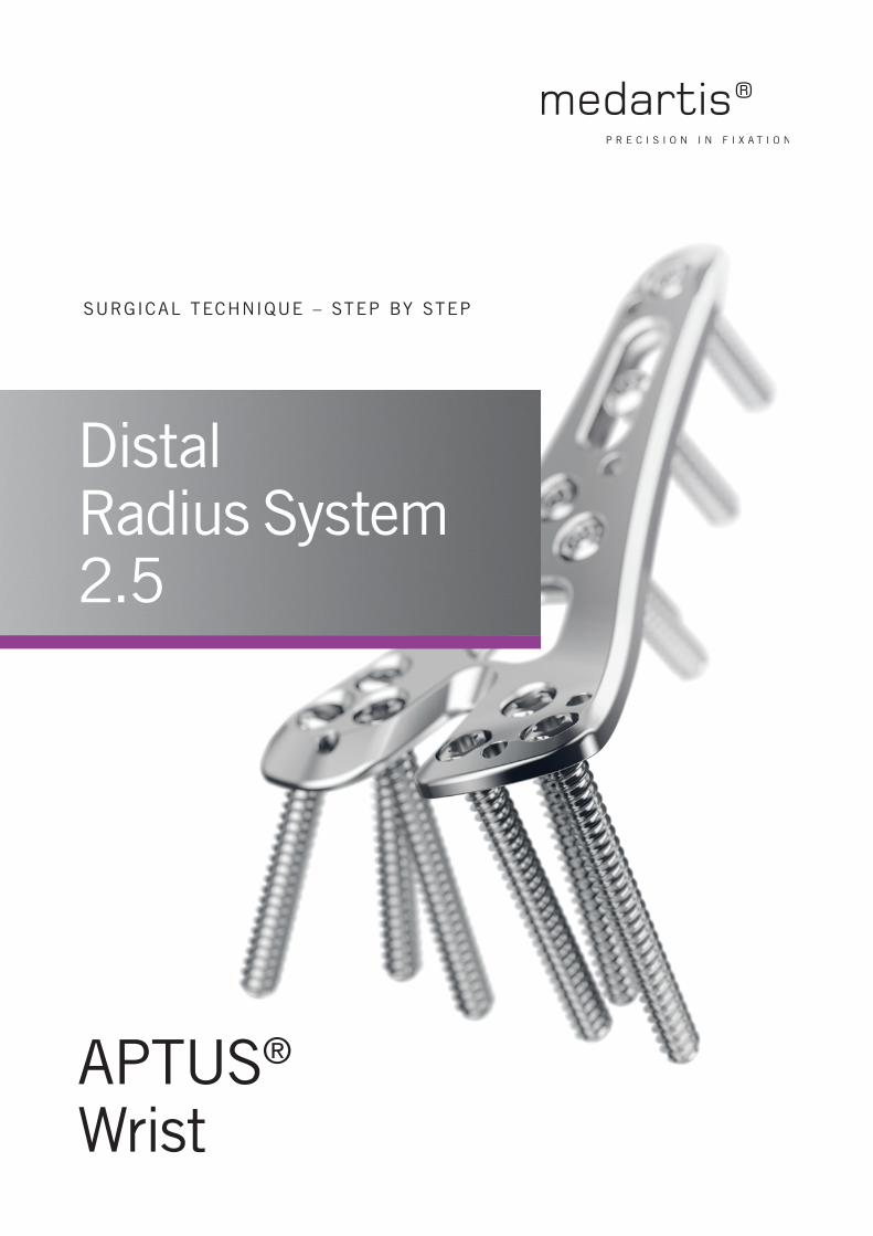
APTUS®
Wrist
SURGICAL TECHNIQUE – STEP BY STEP
Distal Radius System 2.5

2 | Distal Radius System 2.5
www.medartis.com/products/aptus/wrist
Contents
Medartis, APTUS, MODUS, TriLock, HexaDrive and SpeedTip are registered trademarks of Medartis AG / Medartis Holding AG, 4057 Basel, Switzerland
3 Introduction
3 Product Materials
3 Indications
3 Contraindications
3 Color Coding
3 Possible Combination of Plates and Screws
3 Symbols
4 Treatment Concept
5 Instrument Application
5 General Instrument Application
5 Plate Holding and Positioning
5 Plate Bending
8 Cutting
9 Drilling
11 Assigning the Screw Length
12 Screw Pick-Up
13 Specific Instrument Application
13 Drill Guide Blocks
15 Instrument for Restoration of the Volar Tilt
16 Surgical Techniques
16 General Surgical Techniques
16 Lag Screws
17 Distal Two-Row Screw Allocation
18 Specific Surgical Techniques
18 Hook Plates
19 TriLock Lunate Facet Plates
20 TriLock Distal Radius Rim Plates
21 XL Plates with TriLockPLUS
22 TriLock Locking Technology
22 Correct Application of the TriLock Locking Technology
23 Correct Locking (± 15°) of the TriLock Screws in the Plate
24 Appendix
24 Implants and Instruments
For further information regarding the APTUS product line visit:
www.medartis.com/products
Distal Radius System 2.5 | 3
www.medartis.com/products/aptus/wrist
Introduction
Product Materials
All APTUS implants are made of pure titanium (ASTM F67,
ISO 5832-2) or titanium alloy (ASTM F136, ISO 5832-3).
All of the titanium materials used are biocompatible,
corrosion-resistant and non-toxic in a biological environment.
K-wires are made of stainless steel (ASTM F 138);
instruments are made of stainless steel, PEEK, aluminum
or titanium.
Indications
APTUS Radius
• Intra- and extra-articular fractures
• Correction osteotomies
APTUS Ulna
• Management of fractures and osteotomies of the ulna
Contraindications
• Pre-existing or suspected infection at or near the
implantation site
• Known allergies and / or hypersensitivity to implant materials
• Inferior or insufficient bone quality to securely anchor
the implant
• Patients who are incapacitated and/or uncooperative during
the treatment phase
• Growth plates are not to be blocked with plates and screws
Color Coding
System Size Color Code
APTUS 2.5 purple
APTUS 1.5 green
Plates and Screws
Special implant plates and screws have their own color:
Implant plates gold Fixation plates
Implant plates blue TriLock plates (locking)
Implant screws gold Cortical screws (fixation)
Implant screws blue TriLock screws (locking)
Implant screws silver TriLock Express screws (locking)
Implant screws green SpeedTip screws (self-drilling)
Possible Combination of Plates and ScrewsPlates and screws can be combined within one system size:
2.5 TriLock Plates
2.5 Cortical Screws, HexaDrive 7
2.5 TriLock Screws, HexaDrive 7
2.5 TriLock Express Screws, HexaDrive 7
1.5 Fixation Plates
1.5 SpeedTip Screws, HexaDrive 4
Symbols
HexaDrive
See Instructions for Usewww.medartis.com
4 | Distal Radius System 2.5
www.medartis.com/products/aptus/wrist
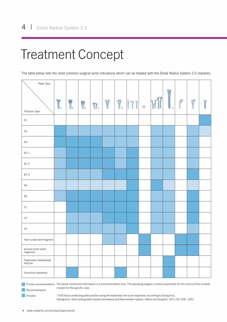
The table below lists the most common surgical wrist indications which can be treated with the Distal Radius System 2.5 implants.
A1
A2
A3
B1.1
B1.2
B1.3
B2
B3
C1
C2
C3
Volar lunate facet fragment
Avulsed small distal fragments
Diaphyseal-metaphyseal fracture
Correction osteotomy
Plate Type
Fracture Type
Treatment Concept
The above-mentioned information is a recommendation only. The operating surgeon is solely responsible for the choice of the suitable implant for the specific case.
* Soft tissue protecting plate position along the watershed line to be respected, according to Soong et al. (Soong et al.; Volar locking plate implant prominence and flexor tendon rupture; J Bone Joint Surg Am. 2011; 93: 328 – 335)
Primary recommendation
Recommendation
Possible
* *****
Distal Radius System 2.5 | 5
www.medartis.com/products/aptus/wrist
Instrument ApplicationGeneral Instrument Application
A-20472.0 – 2.8 Plate Bending Pliers, with Pins
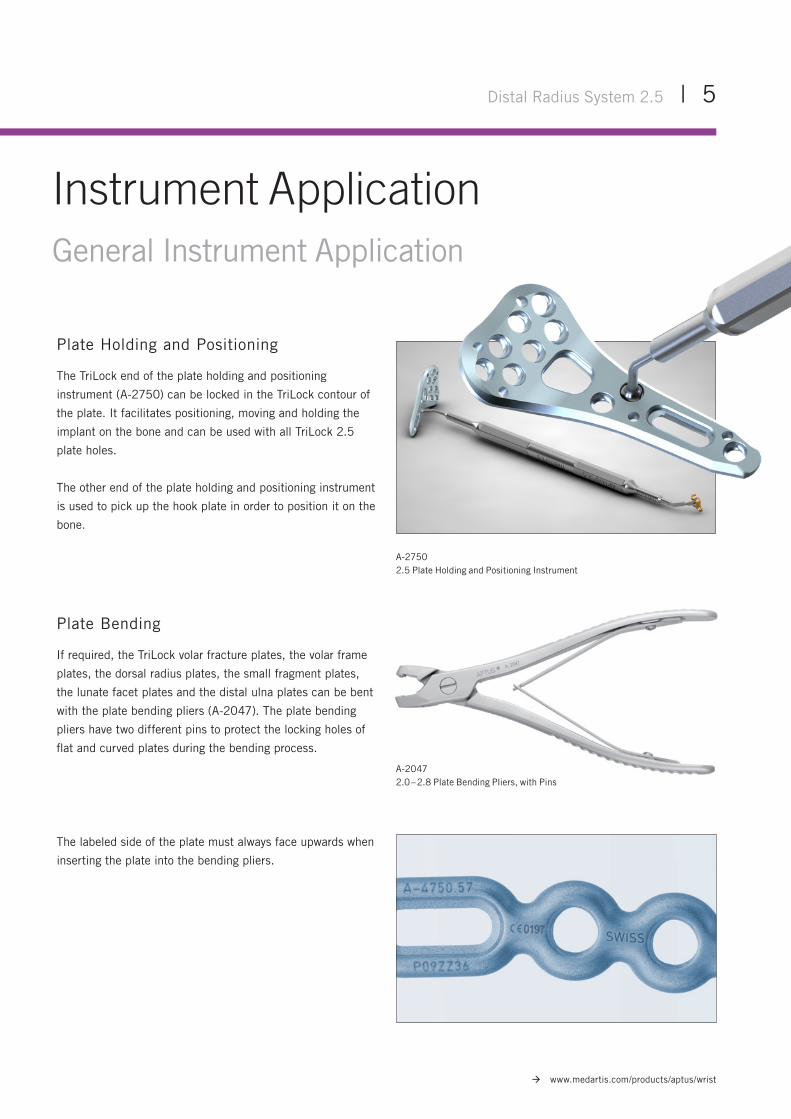
Plate Holding and Positioning
The TriLock end of the plate holding and positioning
instrument (A-2750) can be locked in the TriLock contour of
the plate. It facilitates positioning, moving and holding the
implant on the bone and can be used with all TriLock 2.5
plate holes.
The other end of the plate holding and positioning instrument
is used to pick up the hook plate in order to position it on the
bone.
Plate Bending
If required, the TriLock volar fracture plates, the volar frame
plates, the dorsal radius plates, the small fragment plates,
the lunate facet plates and the distal ulna plates can be bent
with the plate bending pliers (A-2047). The plate bending
pliers have two different pins to protect the locking holes of
flat and curved plates during the bending process.
The labeled side of the plate must always face upwards when
inserting the plate into the bending pliers.
A-27502.5 Plate Holding and Positioning Instrument
6 | Distal Radius System 2.5
www.medartis.com/products/aptus/wrist
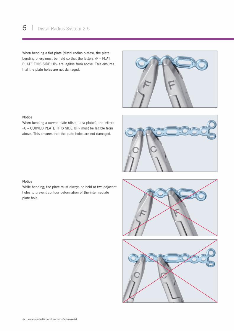
When bending a flat plate (distal radius plates), the plate
bending pliers must be held so that the letters «F – FLAT
PLATE THIS SIDE UP» are legible from above. This ensures
that the plate holes are not damaged.
Notice
When bending a curved plate (distal ulna plates), the letters
«C – CURVED PLATE THIS SIDE UP» must be legible from
above. This ensures that the plate holes are not damaged.
Notice
While bending, the plate must always be held at two adjacent
holes to prevent contour deformation of the intermediate
plate hole.
Distal Radius System 2.5 | 7
www.medartis.com/products/aptus/wrist
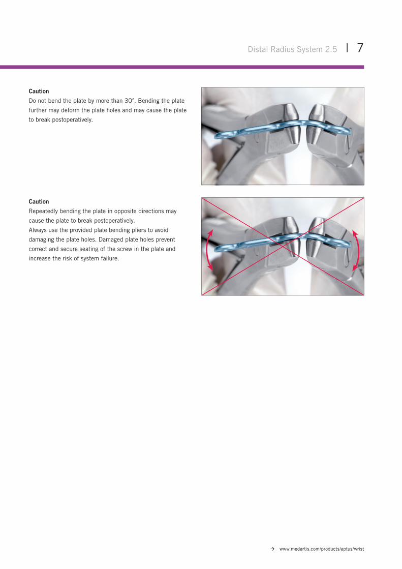
Caution
Do not bend the plate by more than 30°. Bending the plate
further may deform the plate holes and may cause the plate
to break postoperatively.
Caution
Repeatedly bending the plate in opposite directions may
cause the plate to break postoperatively.
Always use the provided plate bending pliers to avoid
damaging the plate holes. Damaged plate holes prevent
correct and secure seating of the screw in the plate and
increase the risk of system failure.
8 | Distal Radius System 2.5
www.medartis.com/products/aptus/wrist
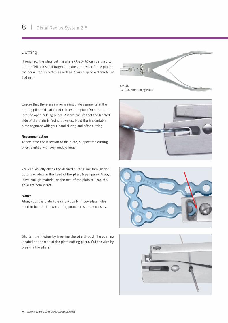
Ensure that there are no remaining plate segments in the
cutting pliers (visual check). Insert the plate from the front
into the open cutting pliers. Always ensure that the labeled
side of the plate is facing upwards. Hold the implantable
plate segment with your hand during and after cutting.
Recommendation
To facilitate the insertion of the plate, support the cutting
pliers slightly with your middle finger.
Cutting
If required, the plate cutting pliers (A-2046) can be used to
cut the TriLock small fragment plates, the volar frame plates,
the dorsal radius plates as well as K-wires up to a diameter of
1.8 mm.
A-20461.2 – 2.8 Plate Cutting Pliers
You can visually check the desired cutting line through the
cutting window in the head of the pliers (see figure). Always
leave enough material on the rest of the plate to keep the
adjacent hole intact.
Notice
Always cut the plate holes individually. If two plate holes
need to be cut off, two cutting procedures are necessary.
Shorten the K-wires by inserting the wire through the opening
located on the side of the plate cutting pliers. Cut the wire by
pressing the pliers.
Distal Radius System 2.5 | 9
www.medartis.com/products/aptus/wrist
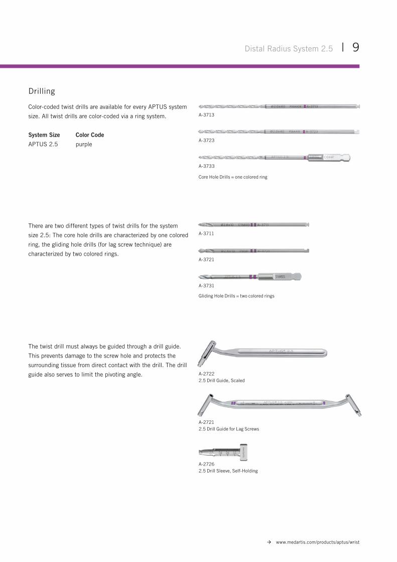
The twist drill must always be guided through a drill guide.
This prevents damage to the screw hole and protects the
surrounding tissue from direct contact with the drill. The drill
guide also serves to limit the pivoting angle. A-27222.5 Drill Guide, Scaled
A-27262.5 Drill Sleeve, Self-Holding
A-27212.5 Drill Guide for Lag Screws
Drilling
Color-coded twist drills are available for every APTUS system
size. All twist drills are color-coded via a ring system.
System Size Color Code
APTUS 2.5 purple
A-3733
Core Hole Drills = one colored ring
A-3723
A-3713
There are two different types of twist drills for the system
size 2.5: The core hole drills are characterized by one colored
ring, the gliding hole drills (for lag screw technique) are
characterized by two colored rings.
Gliding Hole Drills = two colored rings
A-3731
A-3711
A-3721
10 | Distal Radius System 2.5
www.medartis.com/products/aptus/wrist
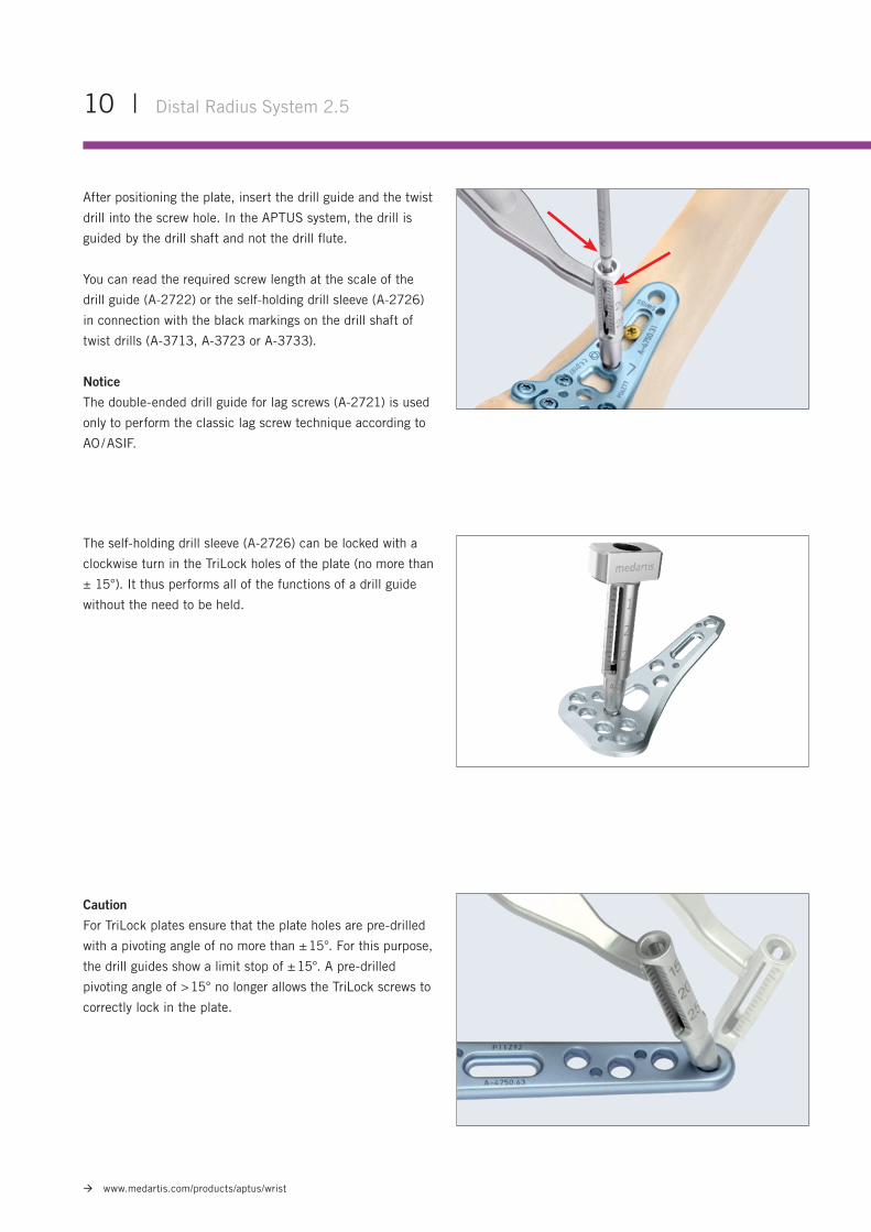
The self-holding drill sleeve (A-2726) can be locked with a
clockwise turn in the TriLock holes of the plate (no more than
± 15°). It thus performs all of the functions of a drill guide
without the need to be held.
Caution
For TriLock plates ensure that the plate holes are pre-drilled
with a pivoting angle of no more than ± 15°. For this purpose,
the drill guides show a limit stop of ± 15°. A pre-drilled
pivoting angle of > 15° no longer allows the TriLock screws to
correctly lock in the plate.
After positioning the plate, insert the drill guide and the twist
drill into the screw hole. In the APTUS system, the drill is
guided by the drill shaft and not the drill flute.
You can read the required screw length at the scale of the
drill guide (A-2722) or the self-holding drill sleeve (A-2726)
in connection with the black markings on the drill shaft of
twist drills (A-3713, A-3723 or A-3733).
Notice
The double-ended drill guide for lag screws (A-2721) is used
only to perform the classic lag screw technique according to
AO / ASIF.
Distal Radius System 2.5 | 11
www.medartis.com/products/aptus/wrist
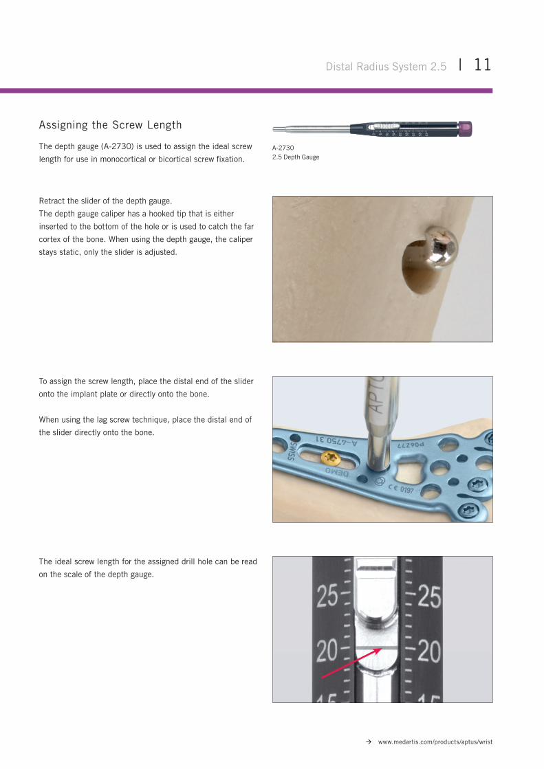
Assigning the Screw Length
The depth gauge (A-2730) is used to assign the ideal screw
length for use in monocortical or bicortical screw fixation.
Retract the slider of the depth gauge.
The depth gauge caliper has a hooked tip that is either
inserted to the bottom of the hole or is used to catch the far
cortex of the bone. When using the depth gauge, the caliper
stays static, only the slider is adjusted.
To assign the screw length, place the distal end of the slider
onto the implant plate or directly onto the bone.
When using the lag screw technique, place the distal end of
the slider directly onto the bone.
The ideal screw length for the assigned drill hole can be read
on the scale of the depth gauge.
A-27302.5 Depth Gauge
12 | Distal Radius System 2.5
www.medartis.com/products/aptus/wrist
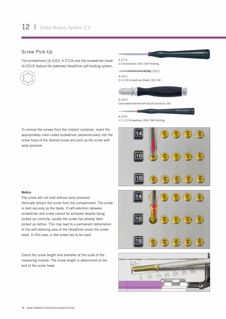
Screw Pick-Up
The screwdrivers (A-2310, A-2710) and the screwdriver blade
(A-2013) feature the patented HexaDrive self-holding system.
To remove the screws from the implant container, insert the
appropriately color-coded screwdriver perpendicularly into the
screw head of the desired screw and pick up the screw with
axial pressure.
Check the screw length and diameter at the scale of the
measuring module. The screw length is determined at the
end of the screw head.
Notice
The screw will not hold without axial pressure!
Vertically extract the screw from the compartment. The screw
is held securely by the blade. If self-retention between
screwdriver and screw cannot be achieved despite being
picked up correctly, usually the screw has already been
picked up before. This may lead to a permanent deformation
of the self-retaining area of the HexaDrive inside the screw
head. In this case, a new screw has to be used.
A-27102.5 Screwdriver, HD7, Self-Holding
A-2073Cannulated Handle with Quick Connector, AO
A-20132.5 / 2.8 Screwdriver Blade, HD7, AO
A-23101.2 / 1.5 Screwdriver, HD4, Self-Holding
Distal Radius System 2.5 | 13
www.medartis.com/products/aptus/wrist
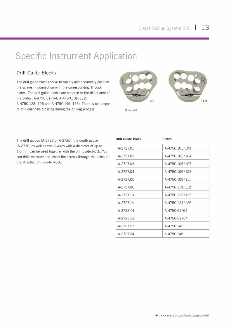
Drill Guide Blocks
The drill guide blocks serve to rapidly and accurately position
the screws in connection with the corresponding TriLock
plates. The drill guide blocks are adapted to the distal area of
the plates (A-4750.61 – 64, A-4750.101– 112,
A-4750.123 – 126 and A-4750.145– 146). There is no danger
of drill channels crossing during the drilling process.
The drill guides (A-2722 or A-2726), the depth gauge
(A-2730) as well as two K-wires with a diameter of up to
1.6 mm can be used together with the drill guide block. You
can drill, measure and insert the screws through the holes of
the attached drill guide block.
Specific Instrument Application
(Example)
rightleft
Drill Guide Block Plates
A-2727.01 A-4750.101 / 103
A-2727.02 A-4750.102 / 104
A-2727.03 A-4750.105 / 107
A-2727.04 A-4750.106 / 108
A-2727.05 A-4750.109 / 111
A-2727.06 A-4750.110 / 112
A-2727.13 A-4750.123 / 125
A-2727.14 A-4750.124 / 126
A-2723.01 A-4750.61 / 63
A-2723.02 A-4750.62 / 64
A-2727.23 A-4750.145
A-2727.24 A-4750.146
14 | Distal Radius System 2.5
www.medartis.com/products/aptus/wrist
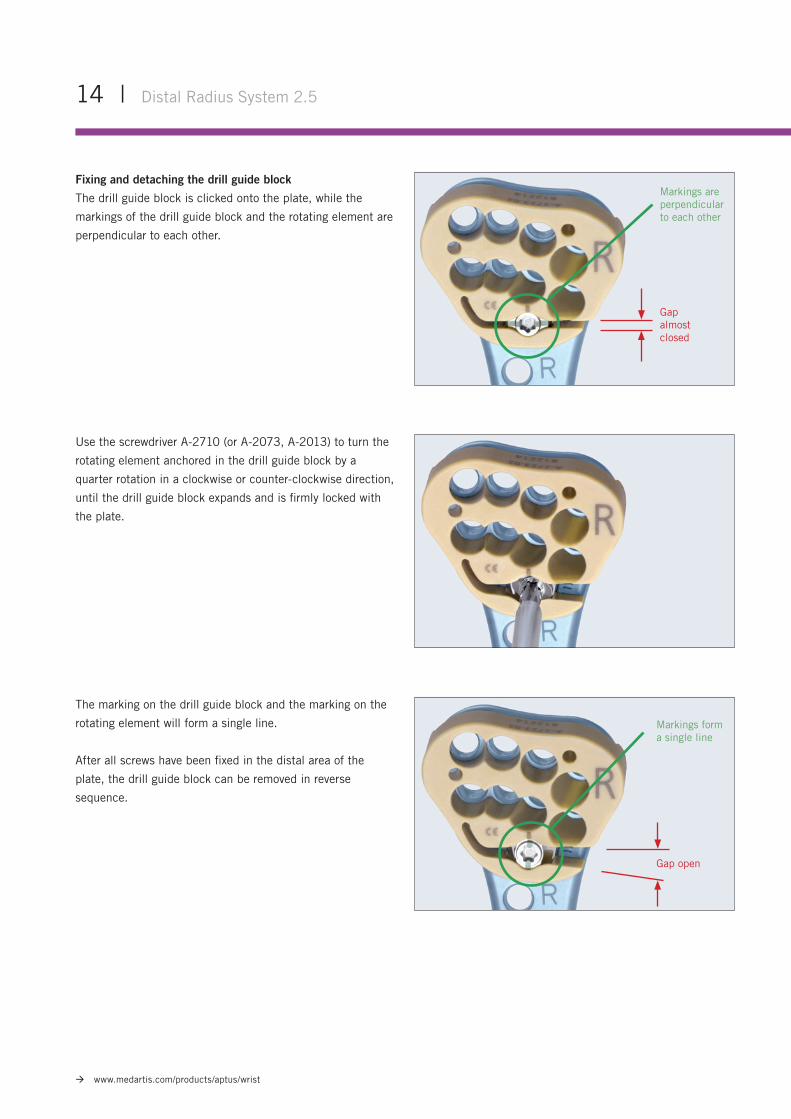
Use the screwdriver A-2710 (or A-2073, A-2013) to turn the
rotating element anchored in the drill guide block by a
quarter rotation in a clockwise or counter-clockwise direction,
until the drill guide block expands and is firmly locked with
the plate.
Markings form a single line
Gap open
The marking on the drill guide block and the marking on the
rotating element will form a single line.
After all screws have been fixed in the distal area of the
plate, the drill guide block can be removed in reverse
sequence.
Gap almost closed
Markings are perpendicular to each other
Fixing and detaching the drill guide block
The drill guide block is clicked onto the plate, while the
markings of the drill guide block and the rotating element are
perpendicular to each other.
22°
Example with 22°
Distal Radius System 2.5 | 15
www.medartis.com/products/aptus/wrist
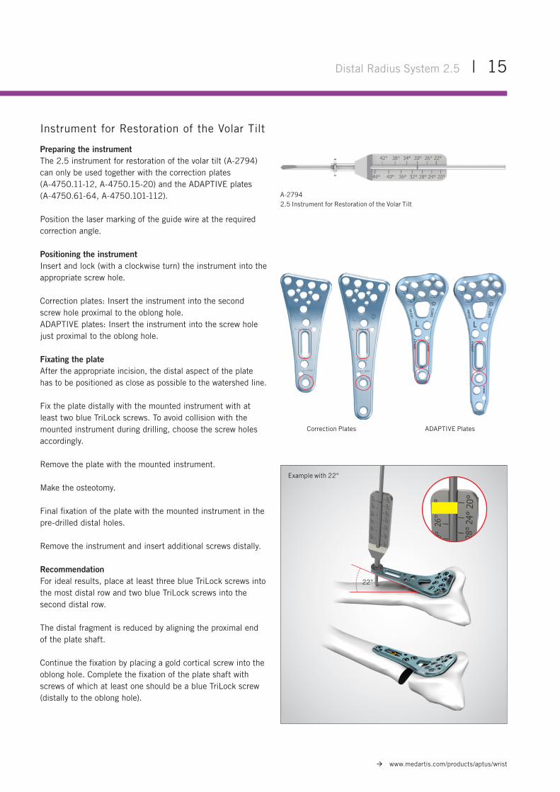
Instrument for Restoration of the Volar Tilt
Preparing the instrumentThe 2.5 instrument for restoration of the volar tilt (A-2794) can only be used together with the correction plates (A-4750.11-12, A-4750.15-20) and the ADAPTIVE plates (A-4750.61-64, A-4750.101-112).
Position the laser marking of the guide wire at the required correction angle.
Positioning the instrumentInsert and lock (with a clockwise turn) the instrument into the appropriate screw hole.
Correction plates: Insert the instrument into the second screw hole proximal to the oblong hole.ADAPTIVE plates: Insert the instrument into the screw hole just proximal to the oblong hole.
Fixating the plateAfter the appropriate incision, the distal aspect of the plate has to be positioned as close as possible to the watershed line.
Fix the plate distally with the mounted instrument with at least two blue TriLock screws. To avoid collision with the mounted instrument during drilling, choose the screw holes accordingly.
Remove the plate with the mounted instrument.
Make the osteotomy.
Final fixation of the plate with the mounted instrument in thepre-drilled distal holes.
Remove the instrument and insert additional screws distally.
RecommendationFor ideal results, place at least three blue TriLock screws into the most distal row and two blue TriLock screws into the second distal row.
The distal fragment is reduced by aligning the proximal end of the plate shaft.
Continue the fixation by placing a gold cortical screw into the oblong hole. Complete the fixation of the plate shaft with screws of which at least one should be a blue TriLock screw (distally to the oblong hole).
A-27942.5 Instrument for Restoration of the Volar Tilt
Correction Plates ADAPTIVE Plates
Surgical TechniquesGeneral Surgical Techniques
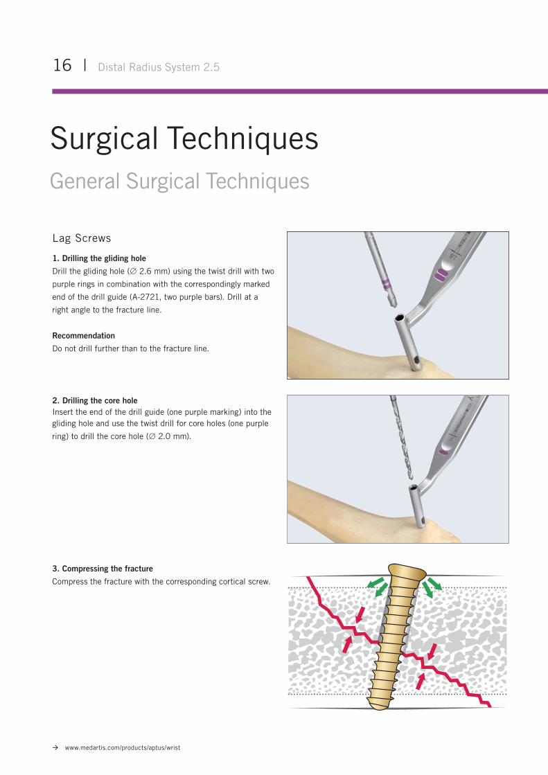
Lag Screws
1. Drilling the gliding hole
Drill the gliding hole (∅ 2.6 mm) using the twist drill with two
purple rings in combination with the correspondingly marked
end of the drill guide (A-2721, two purple bars). Drill at a
right angle to the fracture line.
Recommendation
Do not drill further than to the fracture line.
2. Drilling the core holeInsert the end of the drill guide (one purple marking) into the gliding hole and use the twist drill for core holes (one purple
ring) to drill the core hole (∅ 2.0 mm).
3. Compressing the fracture
Compress the fracture with the corresponding cortical screw.
16 | Distal Radius System 2.5
www.medartis.com/products/aptus/wrist
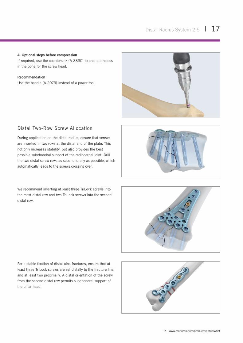
4. Optional steps before compression
If required, use the countersink (A-3830) to create a recess
in the bone for the screw head.
Recommendation
Use the handle (A-2073) instead of a power tool.
Distal Two-Row Screw Allocation
During application on the distal radius, ensure that screws
are inserted in two rows at the distal end of the plate. This
not only increases stability, but also provides the best
possible subchondral support of the radiocarpal joint. Drill
the two distal screw rows as subchondrally as possible, which
automatically leads to the screws crossing over.
We recommend inserting at least three TriLock screws into
the most distal row and two TriLock screws into the second
distal row.
For a stable fixation of distal ulna fractures, ensure that at
least three TriLock screws are set distally to the fracture line
and at least two proximally. A distal orientation of the screw
from the second distal row permits subchondral support of
the ulnar head.
Distal Radius System 2.5 | 17
www.medartis.com/products/aptus/wrist
18 | Distal Radius System 2.5
www.medartis.com/products/aptus/wrist
Specific Surgical Techniques
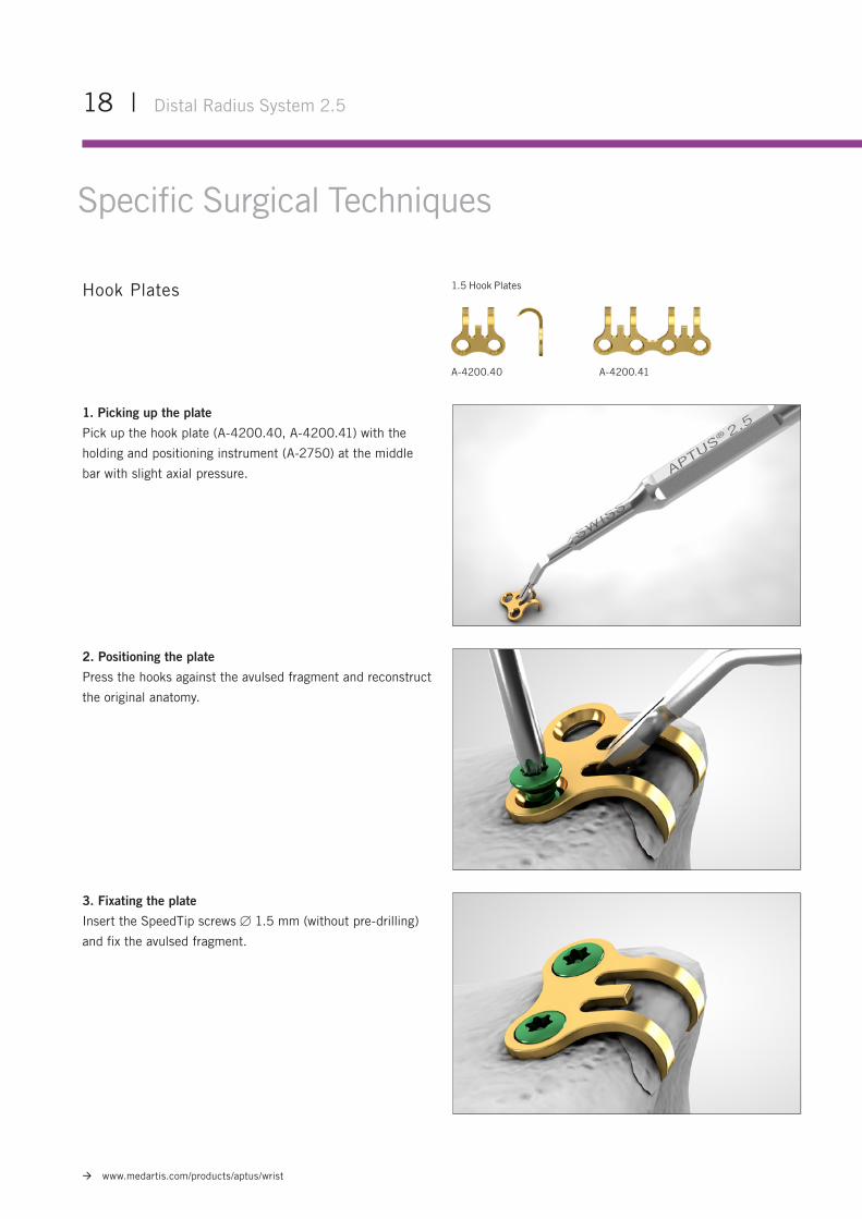
A-4200.40
1.5 Hook Plates
A-4200.41
Hook Plates
1. Picking up the plate
Pick up the hook plate (A-4200.40, A-4200.41) with the
holding and positioning instrument (A-2750) at the middle
bar with slight axial pressure.
2. Positioning the plate
Press the hooks against the avulsed fragment and reconstruct
the original anatomy.
3. Fixating the plate
Insert the SpeedTip screws 1.5 mm (without pre-drilling)
and fix the avulsed fragment.
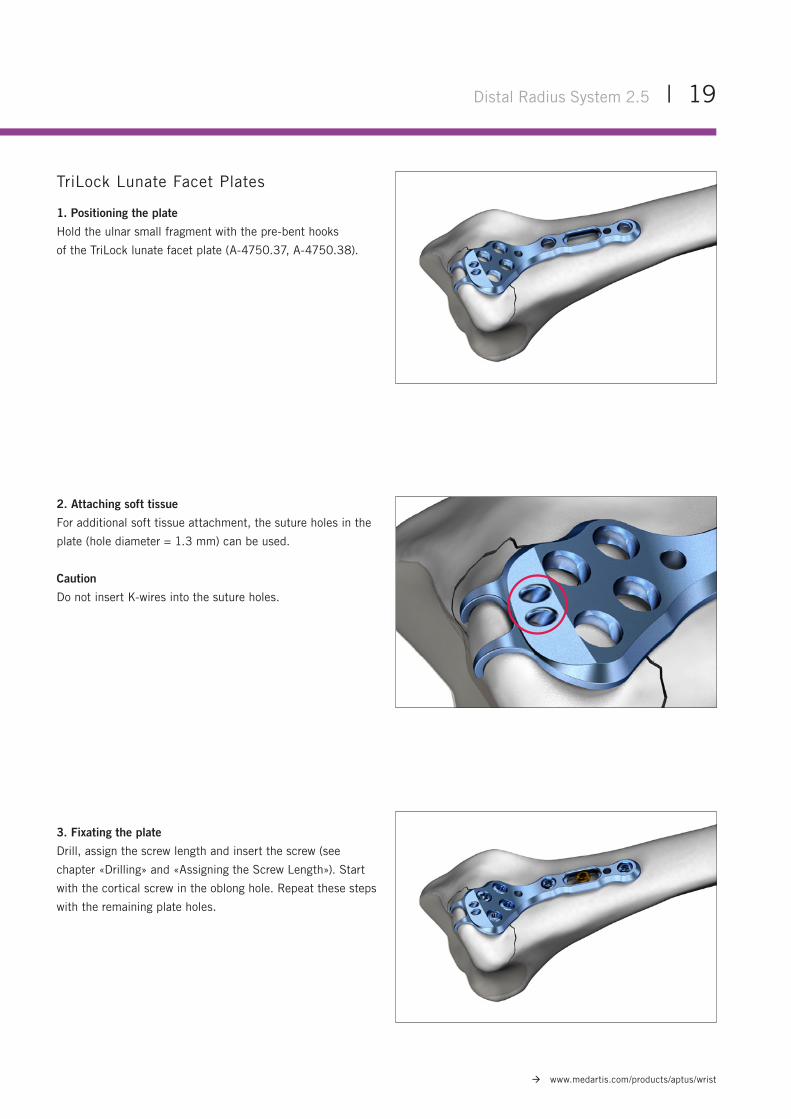
TriLock Lunate Facet Plates
1. Positioning the plate
Hold the ulnar small fragment with the pre-bent hooks
of the TriLock lunate facet plate (A-4750.37, A-4750.38).
2. Attaching soft tissue
For additional soft tissue attachment, the suture holes in the
plate (hole diameter = 1.3 mm) can be used.
Caution
Do not insert K-wires into the suture holes.
3. Fixating the plate
Drill, assign the screw length and insert the screw (see
chapter «Drilling» and «Assigning the Screw Length»). Start
with the cortical screw in the oblong hole. Repeat these steps
with the remaining plate holes.
Distal Radius System 2.5 | 19
www.medartis.com/products/aptus/wrist
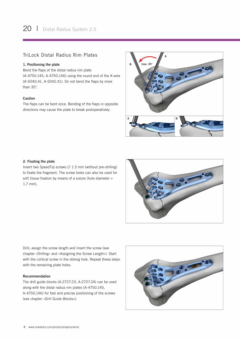
TriLock Distal Radius Rim Plates
1. Positioning the plate
Bend the flaps of the distal radius rim plate
(A-4750.145, A-4750.146) using the round end of the K-wire
(A-5040.41, A-5042.41). Do not bend the flaps by more
than 35°.
Caution
The flaps can be bent once. Bending of the flaps in opposite
directions may cause the plate to break postoperatively.
2. Fixating the plate
Insert two SpeedTip screws 1.5 mm (without pre-drilling)
to fixate the fragment. The screw holes can also be used for
soft tissue fixation by means of a suture (hole diameter =
1.7 mm).
A
A
max. 35°
B
B
20 | Distal Radius System 2.5
www.medartis.com/products/aptus/wrist
Drill, assign the screw length and insert the screw (see
chapter «Drilling» and «Assigning the Screw Length»). Start
with the cortical screw in the oblong hole. Repeat these steps
with the remaining plate holes.
Recommendation
The drill guide blocks (A-2727.23, A-2727.24) can be used
along with the distal radius rim plates (A-4750.145,
A-4750.146) for fast and precise positioning of the screws
(see chapter «Drill Guide Blocks»).
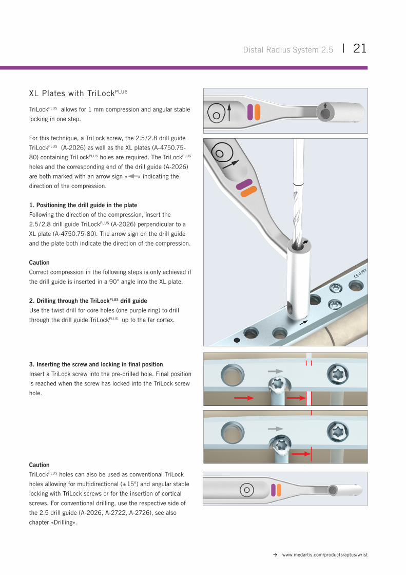
XL Plates with TriLockPLUS
TriLockPLUS allows for 1 mm compression and angular stable
locking in one step.
For this technique, a TriLock screw, the 2.5 / 2.8 drill guide
TriLockPLUS (A-2026) as well as the XL plates (A-4750.75-
80) containing TriLockPLUS holes are required. The TriLockPLUS
holes and the corresponding end of the drill guide (A-2026)
are both marked with an arrow sign « » indicating the
direction of the compression.
1. Positioning the drill guide in the plate
Following the direction of the compression, insert the
2.5 / 2.8 drill guide TriLockPLUS (A-2026) perpendicular to a
XL plate (A-4750.75-80). The arrow sign on the drill guide
and the plate both indicate the direction of the compression.
Caution
Correct compression in the following steps is only achieved if
the drill guide is inserted in a 90° angle into the XL plate.
2. Drilling through the TriLockPLUS drill guide
Use the twist drill for core holes (one purple ring) to drill
through the drill guide TriLockPLUS up to the far cortex.
3. Inserting the screw and locking in final position
Insert a TriLock screw into the pre-drilled hole. Final position
is reached when the screw has locked into the TriLock screw
hole.
Distal Radius System 2.5 | 21
www.medartis.com/products/aptus/wrist
Caution
TriLockPLUS holes can also be used as conventional TriLock
holes allowing for multidirectional (± 15°) and angular stable
locking with TriLock screws or for the insertion of cortical
screws. For conventional drilling, use the respective side of
the 2.5 drill guide (A-2026, A-2722, A-2726), see also
chapter «Drilling».
Insertion Torque MIn
Locking Torque MLock
Insertion Phase
ARelease
BLocking
C
Torq
ue M
Rotational Angle α
22 | Distal Radius System 2.5
www.medartis.com/products/aptus/wrist
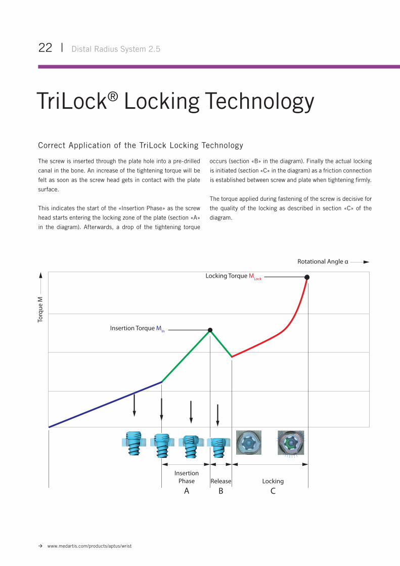
TriLock® Locking Technology
Correct Application of the TriLock Locking Technology
The screw is inserted through the plate hole into a pre-drilled
canal in the bone. An increase of the tightening torque will be
felt as soon as the screw head gets in contact with the plate
surface.
This indicates the start of the «Insertion Phase» as the screw
head starts entering the locking zone of the plate (section «A»
in the diagram). Afterwards, a drop of the tightening torque
occurs (section «B» in the diagram). Finally the actual locking
is initiated (section «C» in the diagram) as a friction connection
is established between screw and plate when tightening firmly.
The torque applied during fastening of the screw is decisive for
the quality of the locking as described in section «C» of the
diagram.
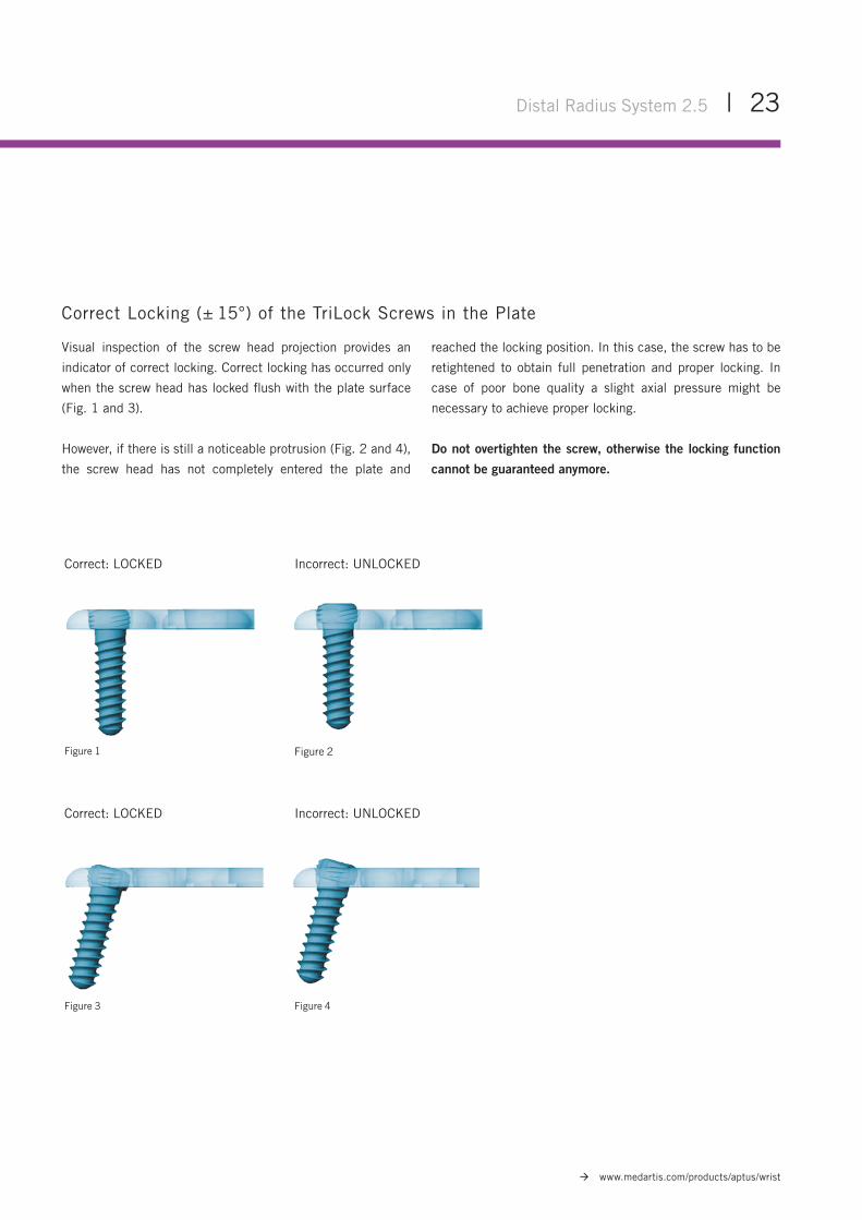
Figure 1
Figure 3
Figure 2
Figure 4
Correct: LOCKED
Correct: LOCKED
Incorrect: UNLOCKED
Incorrect: UNLOCKED
Distal Radius System 2.5 | 23
www.medartis.com/products/aptus/wrist
Correct Locking (± 15°) of the TriLock Screws in the Plate
Visual inspection of the screw head projection provides an
indicator of correct locking. Correct locking has occurred only
when the screw head has locked flush with the plate surface
(Fig. 1 and 3).
However, if there is still a noticeable protrusion (Fig. 2 and 4),
the screw head has not completely entered the plate and
reached the locking position. In this case, the screw has to be
retightened to obtain full penetration and proper locking. In
case of poor bone quality a slight axial pressure might be
necessary to achieve proper locking.
Do not overtighten the screw, otherwise the locking function
cannot be guaranteed anymore.
24 | Distal Radius System 2.5
www.medartis.com/products/aptus/wrist
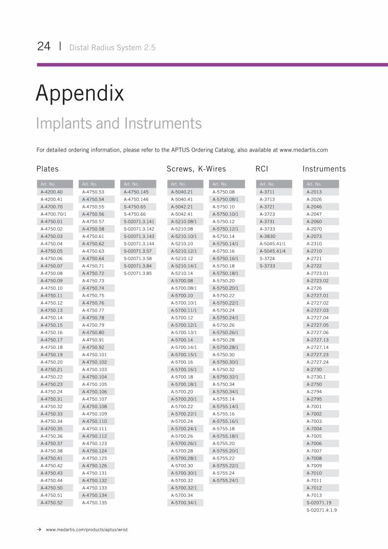
For detailed ordering information, please refer to the APTUS Ordering Catalog, also available at www.medartis.com
AppendixImplants and Instruments
Art. No.
A-4200.40
A-4200.41
A-4700.70
A-4700.70/1
A-4750.01
A-4750.02
A-4750.03
A-4750.04
A-4750.05
A-4750.06
A-4750.07
A-4750.08
A-4750.09
A-4750.10
A-4750.11
A-4750.12
A-4750.13
A-4750.14
A-4750.15
A-4750.16
A-4750.17
A-4750.18
A-4750.19
A-4750.20
A-4750.21
A-4750.22
A-4750.23
A-4750.24
A-4750.31
A-4750.32
A-4750.33
A-4750.34
A-4750.35
A-4750.36
A-4750.37
A-4750.38
A-4750.41
A-4750.42
A-4750.43
A-4750.44
A-4750.50
A-4750.51
A-4750.52
Art. No.
A-4750.53
A-4750.54
A-4750.55
A-4750.56
A-4750.57
A-4750.58
A-4750.61
A-4750.62
A-4750.63
A-4750.64
A-4750.71
A-4750.72
A-4750.73
A-4750.74
A-4750.75
A-4750.76
A-4750.77
A-4750.78
A-4750.79
A-4750.80
A-4750.91
A-4750.92
A-4750.101
A-4750.102
A-4750.103
A-4750.104
A-4750.105
A-4750.106
A-4750.107
A-4750.108
A-4750.109
A-4750.110
A-4750.111
A-4750.112
A-4750.123
A-4750.124
A-4750.125
A-4750.126
A-4750.131
A-4750.132
A-4750.133
A-4750.134
A-4750.135
Art. No.
A-4750.145
A-4750.146
S-4750.65
S-4750.66
S-02071.3.141
S-02071.3.142
S-02071.3.143
S-02071.3.144
S-02071.3.57
S-02071.3.58
S-02071.3.84
S-02071.3.85
Art. No.
A-5040.21
A-5040.41
A-5042.21
A-5042.41
A-5210.08/1
A-5210.08
A-5210.10/1
A-5210.10
A-5210.12/1
A-5210.12
A-5210.14/1
A-5210.14
A-5700.08
A-5700.08/1
A-5700.10
A-5700.10/1
A-5700.11/1
A-5700.12
A-5700.12/1
A-5700.13/1
A-5700.14
A-5700.14/1
A-5700.15/1
A-5700.16
A-5700.16/1
A-5700.18
A-5700.18/1
A-5700.20
A-5700.20/1
A-5700.22
A-5700.22/1
A-5700.24
A-5700.24/1
A-5700.26
A-5700.26/1
A-5700.28
A-5700.28/1
A-5700.30
A-5700.30/1
A-5700.32
A-5700.32/1
A-5700.34
A-5700.34/1
Art. No.
A-3711
A-3713
A-3721
A-3723
A-3731
A-3733
A-3830
A-5045.41/1
A-5045.41/4
S-3724
S-3733
Art. No.
A-2013
A-2026
A-2046
A-2047
A-2060
A-2070
A-2073
A-2310
A-2710
A-2721
A-2722
A-2723.01
A-2723.02
A-2726
A-2727.01
A-2727.02
A-2727.03
A-2727.04
A-2727.05
A-2727.06
A-2727.13
A-2727.14
A-2727.23
A-2727.24
A-2730
A-2730.1
A-2750
A-2794
A-2795
A-7001
A-7002
A-7003
A-7004
A-7005
A-7006
A-7007
A-7008
A-7009
A-7010
A-7011
A-7012
A-7013
S-02071.19
S-02071.4.1.9
Art. No.
A-5750.08
A-5750.08/1
A-5750.10
A-5750.10/1
A-5750.12
A-5750.12/1
A-5750.14
A-5750.14/1
A-5750.16
A-5750.16/1
A-5750.18
A-5750.18/1
A-5750.20
A-5750.20/1
A-5750.22
A-5750.22/1
A-5750.24
A-5750.24/1
A-5750.26
A-5750.26/1
A-5750.28
A-5750.28/1
A-5750.30
A-5750.30/1
A-5750.32
A-5750.32/1
A-5750.34
A-5750.34/1
A-5755.14
A-5755.14/1
A-5755.16
A-5755.16/1
A-5755.18
A-5755.18/1
A-5755.20
A-5755.20/1
A-5755.22
A-5755.22/1
A-5755.24
A-5755.24/1
Plates Screws, K-Wires RCI Instruments

WRIST-01030001_v9 / © 2018-03, Medartis AG, Switzerland. All technical data subject to alteration.
MANUFACTURER & HEADQUARTERS
Medartis AG | Hochbergerstrasse 60E | 4057 Basel / Switzerland
P +41 61 633 34 34 | F +41 61 633 34 00 | www.medartis.com
SUBSIDIARIES
Australia | Austria | Brazil | France | Germany | Mexico | New Zealand | Poland | UK | USA
For detailed information regarding our subsidiaries and distributors, please visit www.medartis.com
Disclaimer: This information is intended to demonstrate the Medartis portfolio of medical devices. A surgeon must always rely on her or his own professional clinical judgement when deciding whether to use a particular product when treating a particular patient. Medartis is not giving any medical advice. The devices may not be available in all countries due to registration and / or medical practices. For further questions, please contact your Medartis representative (www.medartis.com). This information contains CE-marked products.For US only: Federal law restricts this device to sale by or on the order of a physician.