Embed Size (px)
Citation preview
1. Introduction
Product quality and efficiency in the steelmaking indus-try are influenced by the chemical and rheological proper-ties of the slag produced as an integral part of the opera-tion. The chemistry of the slag is controlled by the additionof lime and other fluxes. Fluxes are required in steelmakingbasically for two purposes. Firstly, to lower the meltingpoint of slags so that slags of higher basicity can be used toreduce the level of residuals in steel. Secondly, to decreasethe viscosity of slags and thus speed up refining reactions.BOF steelmaking and ladle refining operations are nor-mally run with slag of high basicity, which is achieved byintroduction of high volumes of lime. Efficient steelmakingpractice requires rapid assimilation of lime by slag, whichis influenced strongly by temperature and slag composition.Mechanisms of lime dissolution into slag under differentconditions have been studied previously.1–9)
Umakoshi et al.,2) studied the dissolution of a rotatingburnt dolomite cylinder in FetO–CaO–SiO2 slag as a func-tion of temperature (1 350–1 400°C) and rotational speed.They found a film of Ca2SiO4 at a short distance from theCaO interface which hindered the dissolution of CaO. Theyalso concluded that the dissolution rate was affected by the(Fe, Mg)O solid solution, which was formed on the surfaceof the burnt lime. Matsushima et al.6) investigated the dis-solution of solid lime by dipping a crystalline lime cylinderinto the static CaO–SiO2–Al2O3 and FeO–CaO–SiO2 slagbath at 1 400°C and 1 500°C and measured the concentra-tion profile in the vicinity of interface. It was shown that
Ca2SiO4 precipitated slightly apart from the interface andthe slag near the interface was enriched in Al2O3 or FeO,which indicated silica depletion due to the formation of theCa2SiO4 film. These results seemed to confirm the longheld belief that when lime is immersed in slag; a layer ofdi-calcium silicate is formed that slows down the dissolu-tion process.
Fluxes such as fluorspar are usually added to increase therate of lime dissolution. However, fluorspar causes emissionof hazardous fluoride species, leaching of fluoride fromgenerated slag, and refractory wear. These factors anddwindling accessible supplies of fluorspar have stimulated asearch for alternative fluxes. The possibility of fluorsparsubstitution has been previously examined by a number ofresearchers.10–17) Tribe et al.13) presented a series of labora-tory and industrial tests in which fluorspar in steelmakingslag was partially or fully replaced with feldspathoid min-eral (a group of sodium and potassium aluminosilicate).They found that nepheline syenite tailing (NST) can be asuitable substitute for the fluorspar. NST slag exhibited asimilar rheological behaviour to the CaF2 slag. Also, whenusing NST, the steel chemistry was not affected and ade-quate desulphurisation was achieved. Singh et al.16) con-ducted extensive industrial trials to show that the fluidity ofslag with ilmenite (FeTiO3) is very close to the fluidity ofthe fluorspar-containing slag, and concluded that ilmenitecan be used as a fluorspar replacement in open hearth steel-making. Poggi et al.17) also found that the fluorspar and il-menite have close melting points and both are very fluidwhen molten.
32© 2007 ISIJ
ISIJ International, Vol. 47 (2007), No. 1, pp. 32–37
Dissolution of Dense Lime in Molten Slags under StaticConditions
Shahriar AMINI,1) Michael BRUNGS2) and Oleg OSTROVSKI3)
1) Formerly, School of Chemical Sciences and Engineering, The University of New South Wales and CSIRO Minerals. Now atSchool of Chemical Engineering and Analytical Science, The University of Manchester, UK., PO Box 88, Sackville St.,Manchester, M60 1 QD, UK. E-mail: [email protected] 2) School of Chemical Sciences and Engineering,The University of New South Wales, NSW, 2052, Australia. 3) School of Material Sciences and Engineering, TheUniversity of New South Wales, NSW, 2052, Australia.
(Received on July 3, 2006; accepted on September 20, 2006 )
Static dissolution of CaO into a CaO–SiO2–Al2O3 slag with fluxing agents (fluorspar, ilmenite and nephelinesyenite) was studied using two experimental techniques. In one method, the slag was packed into denseCaO crucibles, and heated to 1 500°C/1 600°C. After reaction, the crucible was air cooled and cross-sec-tioned. In the second technique, slag with a piece of lime was heated in a platinum capsule. The develop-ment of the Ca2SiO4 phase at the lime/slag interface and the CaO dissolved in the slag from the lime speci-men were examined by Electron Probe Micro Analysis and Scanning Electron Microscopy. Ilmenite andnepheline syenite were found to be effective substitutes for fluorspar, increasing the CaO dissolution rate inthe slag.
KEY WORDS: lime; dissolution; slag; fluorspar; nepheline syenite; ilmenite.
The current study examines the dissolution of lime atsteelmaking temperatures in calcium alumino-silicate slagswith basicity of 1. The aim of this study is to examine theeffect of addition of 10 wt% fluxing agents: fluorspar,nepheline syenite and ilmenite on the rate of lime dissolu-tion in the slag. While acknowledging that in industry, theburnt lime is porous (more than 50% porosity for soft-burnt lime and about 25% porosity for hard-burnt), it wasdecided to use a low porosity lime (8.4%). This was to en-sure a sharp lime/slag boundary and consequently bettercontrol of experimental conditions.
2. Experimental
Static dissolution of CaO into slag was studied by twoexperimental techniques. Firstly, holding slag in a denselime crucible, varying reaction time, temperature and slagchemistry. Secondly, by reacting a piece of lime with slagin a small platinum crucible, varying temperature.
2.1. Materials
Manufacture of the lime crucibles included the followingoperations. The limestone powder with 50–70 mm particlesize was milled with alumina balls producing 0.8–1 mmparticles that were then calcined to CaO and pressed in amould and subsequently fired to provide the necessary den-sity and strength. This technique allowed a close control ofbulk density and apparent porosity by precisely varyingcompacting pressure, sintering temperature, rate of heatingand cooling and sintering time.
The experimental slags were prepared in a platinum cru-cible by melting a mixture of slag components, quenchingthe melt and then re-melting to ensure slags’ homogeneity.The master slag was a three component CaO–SiO2–Al2O3
system with 45 wt% CaO, 45 wt% SiO2, and 10 wt% Al2O3.Flux additions were made by adding 10 wt% of fluorsparand fluorspar replacement candidates to the master slag.The flux compositions used in the present work are pre-sented in Table 1 and the chemical composition of slagsstudied in the present work are tabulated in Table 2. In thecase of the CaF2 addition, subsequent analysis revealed that
the CaF2 content of the resultant slag was only 5.7 wt% in-dicating a loss of fluorine. The fluorine loss and oxidationof calcium of fluorspar was previously reported by Shimizuet al.18)
2.2. Experimental Procedure
The dissolution of dense lime in molten slag was studiedat 1 500 and 1 600°C as a function of time and slag compo-sition. After cooling the samples the chemical compositionof various elements in the liquid slag and also phase identi-fication were quantitatively performed by EPMA mappingand SEM analysis.
In the first experimental technique performed at The Uni-versity of New South Wales, the CaO crucible was filledwith slag and charged to the muffle furnace. A sample washeated slowly at 100°C/h up to 1 250°C which is below themelting point of slag studied in this work, in order to mini-mize the risk of thermal shock in the crucible and thenheated quickly at 600°C/h up to 1 500°C/1 600°C. Zero re-action time was defined as the time when the furnace firstreached the desired temperature. After the required reactiontimes of 30 and 60 min, the crucible and slag were takenout of the furnace and quickly quenched in air. Due to thesevere thermal shock, in most cases and especially experi-ments at 1 600°C, the lime crucible was shattered intopieces after air quenching, making it difficult to prepare asample of lime with attached slag for further analysis. Therecovered crucible with its slag content was cross-sectionedand mounted in resin.
Samples were prepared with a flat and well-polished sur-face, finished to (0–1) mm and then coated with a carbonlayer (thickness �200 Å) for electron probe microanalysis(EPMA). A CAMECA SX50 EPMA at The University ofNew South Wales was used in quantitative analysis of samples. All samples were examined using an acceleratingvoltage of 15 kV, a beam current of 20 nA and a beam sizeof 1 mm. Point analysis was performed for each distinctphase identified using back-scattered electron mode. AMATLAB19) program was developed to convert the concen-tration profile of each element in the matrix to the molepercentage of various oxides and determined the phase lo-cations in the ternary phase diagram. The phase diagramsat different temperatures were obtained from FactSage.20)
The elemental distribution in the slag adjacent to thelime/slag interface was mapped by 2 mm step size stagemovement in an area of 512 by 512 mm size and at a 256 by256 image resolution. A MATLAB program was also de-veloped to analyze the results from mapping. The programenabled recognition of Ca2SiO4 and Ca3SiO5 phases in themapped area.
The formation of solid phases formed at the CaO cru-cible/slag interface was further investigated by carrying outanother series of static experiments at Commonwealth Sci-
ISIJ International, Vol. 47 (2007), No. 1
33 © 2007 ISIJ
Table 1. Chemical compositions of fluxes.
Table 2. Chemical compositions of slags.
entific and Industrial Research Organization (CSIRO) divi-sion of Minerals, in which a platinum capsule was used tocontain the slag and a piece of lime. The small platinumcapsules (15 mm ID by 32 mm height) were made by weld-ing two sides of a thin platinum foil. About 0.5 g of slagand 0.6–0.7 g of dense chipped CaO from crucible pieceswere contained in the platinum capsule and were held verti-cally by shallow holes drilled in a refractory brick. Themuffle furnace was ramped up to 1 000°C at the rate of100°C/h and then to the target temperature at the rate of800°C/h. After reaching the temperatures of 1 500 and1 600°C and exposure at temperature for the required reac-tion time, the platinum capsules were taken out of the muf-fle furnace and rapidly quenched on a brass plate, whichwas also cooled by an air flow on its back surface. The useof thin and small platinum foil in this technique provided avery fast cooling rate compared to the previous technique.The samples from the reaction experiments were cut,mounted in resin and coated with a carbon layer. Thesesamples were analyzed using a Philips XL30 ScanningElectron Microscope at University of Melbourne. The elec-tron optical system accelerating voltage was 20 kV.
3. Experimental Results and Discussion
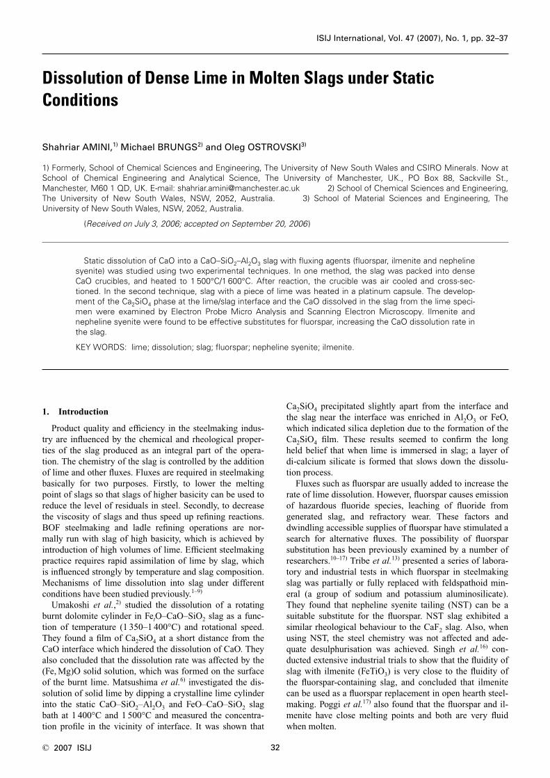
Electron Micrographs of the sample at 1 500°C from thelime crucible experiment (Fig. 1(a)) show formation of aCa2SiO4 layer, which was also observed by Matsushima etal.6) However at 1 600°C, no discrete layer of Ca2SiO4 wasdetected (Fig. 1(b)). The dendritic appearance of the crys-
tallites indicates that they were not present in the liquidphase but crystallised out during cooling. Although a layerof Ca2SiO4 was not observed at 1 600°C, it does not meanthat it was not formed at this temperature. The loss of mate-rials at the lime/slag interface because of the lime crucibleshattering on air quenching or the loss of the layer in sam-ple preparation cannot be excluded. “Slag composition” isthe composition of the slag at experimental temperaturesdetermined by analysis of quenched samples that consistedof both crystalline and glassy phases. Where the composi-tion of these phases has been determined, it will be referredto as the crystalline or glassy phase composition.
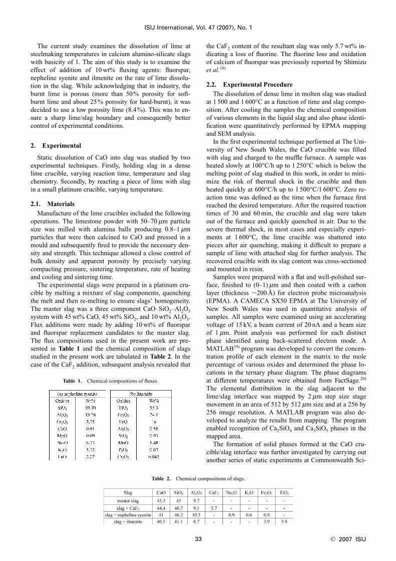
Change in the slag chemical and phase composition inthe process of lime dissolution measured by EPMA at1 500°C is shown in the CaO–SiO2–Al2O3 phase diagram inFig. 2. After achieving 1 500°C (zero time), CaO concen-tration in the slag increased from the initial 45 to 48 wt%.After 30 min reaction, it reached 52 wt% and increased fur-ther to 54 wt% after 60 min. In the CaO–SiO2–Al2O3 phasediagram, these compositions are within the liquid area (Fig.2). At zero reaction time, the observed presence of theCa2SiO4 phase at the slag crucible boundary (Fig. 1(a)) isthe result of local non equilibrium conditions. The growthrate of di-calcium layer at 1 500°C was measured by linescan with EPMA. The thickness of the layer is shown inTable 3. The measurement shows that at zero reaction time,the Ca2SiO4 layer has already been formed with a thicknessof 164 mm, although the CaO content in the liquid slag wasoutside the Ca2SiO4–liquid equilibrium curve. This means
ISIJ International, Vol. 47 (2007), No. 1
34© 2007 ISIJ
Fig. 1. SEM of base slag in the lime crucible experiments fortime�0 with 1 000 magnification at (a) 1 500°C, (b)1 600°C.
Fig. 2. The composition of bulk slag at various reaction times(min) in phase diagram for basic slag at 1 500°C.
Table 3. Growth of Ca2SiO4 layer at 1 500°C when the slag isreacted with CaO in the lime crucible and platinumcapsule.
that dissolution of lime into the slag occurred through thedi-calcium silicate layer. The liquid phase compositionachieved the equilibrium with Ca2SiO4 (Ca2SiO4–liquidcurve on the phase diagram) in 30 min. Slag CaO concen-tration increased slightly further with 1 h exposure. Obvi-ously the dissolution of lime has been hindered by the for-mation of the Ca2SiO4 layer, and the rate of the Ca2SiO4
layer growth was greater than the its dissolution rate. Thegrowth of the Ca2SiO4 layer was accompanied by a changein the chemistry of the liquid slag along the Ca2SiO4–liquidcurve in accordance with the phase diagram in Fig. 2; theliquid slag was depleted of SiO2 and enriched with Al2O3,while the CaO concentration in liquid phase changedslightly, although its total concentration increased as a re-sult of increasing thickness of the Ca2SiO4 layer.
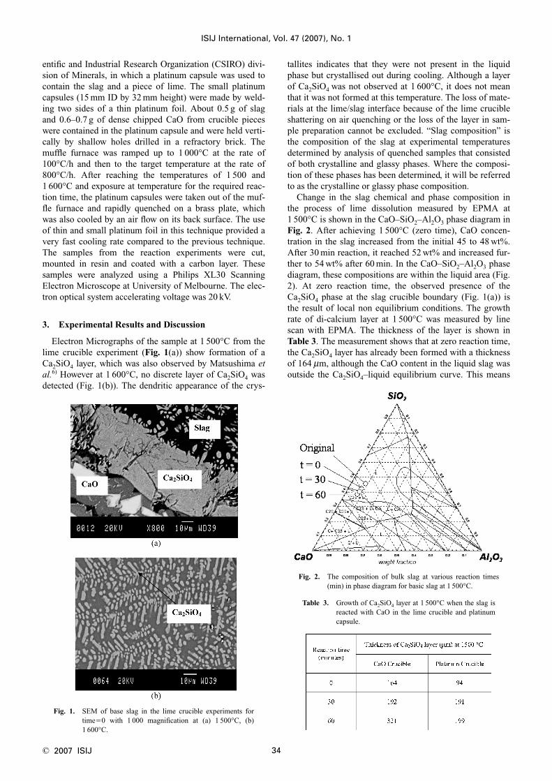
At 1 600°C the change in slag chemical and phase com-position in process of lime dissolution measured by EPMAis shown in the CaO–SiO2–Al2O3 phase diagram in Fig. 3.The initial dissolution rate of CaO into the slag was muchfaster than at 1 500°C. By “zero” reaction time, CaO con-centration in the slag increased from 45 to 53 wt%, which isvery close to the Ca2SiO4–liquid equilibrium curve. Changein the slag’s CaO content with increasing reaction time wassmall (to 54–55 wt%) indicating that dissolution of limehad slowed dramatically and at this CaO content, the slag issaturated with di-calcium silicate. The composition of liq-uid slag analyzed by EPMA revealed an increase in aluminaand a decrease in silica in the slag which indicates forma-tion of the di-calcium silicate phase. Total content of CaOin the slag was about the same at 1 500°C and 1 600°C after dissolution for 30 min (52–54 wt%) and 60 min (53–55 wt%). The fact that the CaO content of slag has not beenincreased at 1 600°C and after 1 h of reaction shows that alayer of di-calcium was formed on the lime and slag inter-face.
In experiments, conducted in platinum capsule, a solidphase product layer was formed between the lime particlesand the slag at both temperatures, which was identified byEDS analysis as Ca2SiO4. At 1 500°C, the formation of re-action layer at the lime/slag interface at 1 500°C for the re-action times of 0, 30 and 60 min was in agreement with the
observation from the previous experimental series. The mi-crographs of the reaction layer at 1 500°C and its growth isillustrated in Fig. 4. The average growth rate of the di-cal-cium layer as shown in Table 3 differs from the result of theexperiments conducted in lime crucible. This could be dueto the different slag to lime specimen ratio and also differ-ent cooling rate in both experimental techniques.
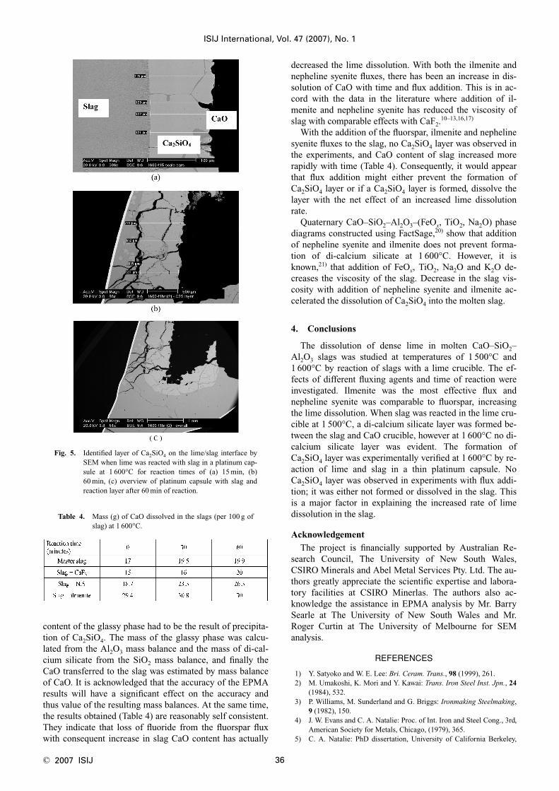
At 1 600°C, the experiments with platinum capsule wereperformed at the reaction times of 15, 30 and 60 min. Thesample recovery during these experiments was more diffi-cult than the experiments done at 1 500°C. The results forexperiments at 15 and 60 min of reaction time shown inFig. 5 clearly indicate the formation of Ca2SiO4, whichgrows with time. For the experiment at reaction time of30 min, the Ca2SiO4 was not recovered; it was presumablylost during quenching.
Mass balance calculations, based on the EPMA analysisof a glassy phase, were used to estimate the quantity of cal-cium oxide transferred to the slag at 1 600°C with additionof various fluxes in the lime crucible experiments (Table 4).The underlying assumption was that the increased alumina
ISIJ International, Vol. 47 (2007), No. 1
35 © 2007 ISIJ
Fig. 3. The composition of bulk slag at various reaction times(min) in phase diagram for basic slag at 1 600°C.
Fig. 4. Identified layer of Ca2SiO4 on the lime/slag interface bySEM when lime was reacted with slag in a platinum cap-sule at 1 500°C for reaction times of (a) 0, (b) 30 min and(c) 60 min.
content of the glassy phase had to be the result of precipita-tion of Ca2SiO4. The mass of the glassy phase was calcu-lated from the Al2O3 mass balance and the mass of di-cal-cium silicate from the SiO2 mass balance, and finally theCaO transferred to the slag was estimated by mass balanceof CaO. It is acknowledged that the accuracy of the EPMAresults will have a significant effect on the accuracy andthus value of the resulting mass balances. At the same time,the results obtained (Table 4) are reasonably self consistent.They indicate that loss of fluoride from the fluorspar fluxwith consequent increase in slag CaO content has actually
decreased the lime dissolution. With both the ilmenite andnepheline syenite fluxes, there has been an increase in dis-solution of CaO with time and flux addition. This is in ac-cord with the data in the literature where addition of il-menite and nepheline syenite has reduced the viscosity ofslag with comparable effects with CaF2.
10–13,16,17)
With the addition of the fluorspar, ilmenite and nephelinesyenite fluxes to the slag, no Ca2SiO4 layer was observed inthe experiments, and CaO content of slag increased morerapidly with time (Table 4). Consequently, it would appearthat flux addition might either prevent the formation ofCa2SiO4 layer or if a Ca2SiO4 layer is formed, dissolve thelayer with the net effect of an increased lime dissolutionrate.
Quaternary CaO–SiO2–Al2O3–(FeOx, TiO2, Na2O) phasediagrams constructed using FactSage,20) show that additionof nepheline syenite and ilmenite does not prevent forma-tion of di-calcium silicate at 1 600°C. However, it isknown,21) that addition of FeOx, TiO2, Na2O and K2O de-creases the viscosity of the slag. Decrease in the slag vis-cosity with addition of nepheline syenite and ilmenite ac-celerated the dissolution of Ca2SiO4 into the molten slag.
4. Conclusions
The dissolution of dense lime in molten CaO–SiO2–Al2O3 slags was studied at temperatures of 1 500°C and1 600°C by reaction of slags with a lime crucible. The ef-fects of different fluxing agents and time of reaction wereinvestigated. Ilmenite was the most effective flux andnepheline syenite was comparable to fluorspar, increasingthe lime dissolution. When slag was reacted in the lime cru-cible at 1 500°C, a di-calcium silicate layer was formed be-tween the slag and CaO crucible, however at 1 600°C no di-calcium silicate layer was evident. The formation ofCa2SiO4 layer was experimentally verified at 1 600°C by re-action of lime and slag in a thin platinum capsule. NoCa2SiO4 layer was observed in experiments with flux addi-tion; it was either not formed or dissolved in the slag. Thisis a major factor in explaining the increased rate of limedissolution in the slag.
Acknowledgement
The project is financially supported by Australian Re-search Council, The University of New South Wales,CSIRO Minerals and Abel Metal Services Pty. Ltd. The au-thors greatly appreciate the scientific expertise and labora-tory facilities at CSIRO Minerlas. The authors also ac-knowledge the assistance in EPMA analysis by Mr. BarrySearle at The University of New South Wales and Mr.Roger Curtin at The University of Melbourne for SEManalysis.
REFERENCES
1) Y. Satyoko and W. E. Lee: Bri. Ceram. Trans., 98 (1999), 261.2) M. Umakoshi, K. Mori and Y. Kawai: Trans. Iron Steel Inst. Jpn., 24
(1984), 532.3) P. Williams, M. Sunderland and G. Briggs: Ironmaking Steelmaking,
9 (1982), 150.4) J. W. Evans and C. A. Natalie: Proc. of Int. Iron and Steel Cong., 3rd,
American Society for Metals, Chicago, (1979), 365.5) C. A. Natalie: PhD dissertation, University of California Berkeley,
ISIJ International, Vol. 47 (2007), No. 1
36© 2007 ISIJ
Table 4. Mass (g) of CaO dissolved in the slags (per 100 g ofslag) at 1 600°C.
Fig. 5. Identified layer of Ca2SiO4 on the lime/slag interface bySEM when lime was reacted with slag in a platinum cap-sule at 1 600°C for reaction times of (a) 15 min, (b)60 min, (c) overview of platinum capsule with slag andreaction layer after 60 min of reaction.
(1978).6) M. Matsushima, S. Yadoomaru, K. Mori and Y. Kawai: Trans. Iron
Steel Inst. Jpn., 17 (1977), 442.7) F. Noguchi, Y. Ueda and T. Yanagase: Proc. World Min. Met. Tech-
nol., Vol. 2, American Institute of Mining, Metallurgical and Petro-leum Engineers, New York, (1976), 685.
8) H. Kimura, T. Yanagase, F. Noguchi and Y. Ueda: J. Jpn. Inst. Met.,38 (1974), 226.
9) W. J. Schlitt and G. W. Healy: Am. Ceram. Soc. Bull., 50 (1971), 954.10) W. F. Caley and J. B. MacDonald: Ironmaking Steelmaking, 28
(2001), 96.11) J. R. MacLean, P. W. Kingston, J. B. MacDonald and W. F. Caley:
Ironmaking Steelmaking, 24 (1997), 406.12) T. S. Tribe, P. W. Kingston and W. F. Caley: Can. Metall. Q., 36
(1997), 95.13) T. S. Tribe, P. W. Kingston, J. B. MacDonald and W. F. Caley: Iron-
making Steelmaking, 21 (1994), 145.
14) P. W. Kingston and W. F. Caley: Miner. Eng., 2 (1989), 207.15) R. H. Nafziger and G. W. Elger: New Steelmaking Technology From
the Bureau of Mines, Chicago, Illinois, USA, (1988), 23–7.16) B. N. Singh, Y. F. Ravat, A. Chatterjee and P. K. Chakravarty: Iron-
making Steelmaking, 4 (1977), 170.17) D. Poggi and H. Y. Lee: Can. Metall. Q., 13 (1974), 529.18) K. Shimizu, T. Suzuki, I. Jimbo and A. W. Cramb: Seventy Ninth
Conf. of the Steelmaking Division of the Iron and Steel Society, Ironand Steel Society/AIME, Pittsburgh, (1996), 727.
19) MATLAB, The Math Works, Inc, USA, (2000).20) C. W. Bale, P. Chartrand, S. A. Degterov, G. Eriksson, K. Hack, R.
Ben Mahfoud, J. Melancon, A. D. Pelton and S. Petersen: FactSage,École Polytechnique CRCT, Canada and GTT-Technologies GmbH,Germany, (2003).
21) V. D. Eisenhuttenleute: Slag Atlas, 2nd ed, Verlag Stahleisen GmbH,Düsseldorf, (1995), 21.
ISIJ International, Vol. 47 (2007), No. 1
37 © 2007 ISIJ