Embed Size (px)
Citation preview
Foundation Field bus Interoperability Test, System Configuration and Loop Design-(EMERSON)
by
Syaza Othman
Dissertation submitted in partial fulfilment of
the requirements for the
Bachelor of Engineering (Hons)
(Electrical and Electronics Engineering)
DECEMBER 2009
Universiti Teknologi PETRONAS Bandar Seri Iskandar 31750 Tronoh Perak Darul Ridzuan
CERTIFICATION OF APPROVAL
FOUNDATION Fieldbus lnteroperability Testing (FFIT). System Configuration and Loop Design
Approved by,
by
Syaza Othman
A project dissertation submitted to the
Electrical and Electronics Engineering
Universiti feknologi PEfRONAS
in partial fulfilment of the requirement for the
BACHELOR OF ENGINEERING (Hons)
(ELECTRICAL AND ELECTRONICS ENGINEERING)
(Dr. Nordin b Saad)
UNIVERSITI TEKNOLOGI PETRONAS
TRONOH, PERAK
DECEMBER 2009

CERTIFICATION OF ORIGINALITY
This is to certify that I am responsible for the work submitted in this project, that the
original work is my own except as specified in the references and acknowledgements,
and that the original work contained herein have not been undertaken or done by
unspecified sources or persons.
SY AZ OTHMAN (7659)
This report discusses the progress work that has been done Foundation Fieldbus
Interoperability Test (FFIT) System Configuration and Loop Design for Emerson
Host. In this report, several researches on fieldbus system and the needs of
interoperability testing and loop design are briefly discussed as well as the
continuation of testing work from FYP l(Basic Test).
Tills project is aligned With the FFIT SKG 14tl\ team project from PETRONAS. All
the standard testing procedures and results is documented for future review. This
project requires a deep understanding on the fieldbus technology which includes the
study on fieldbus technology architecture, wiring, control system and communication
network. From the testing, Foundation Fieldbus system for Emerson Host is found to
be interopembility which means the system can communicate not just within it self
but also with instruments from other vendors. The results of the testing are discussed
briefly in Chapter 4.
iv
AC:KNOWJ..EDGEMJ:NT
Thank you God Almighty for the successfulness of this project. First of all, I
would like to express my deepest gratitude to my supervisor, AP Dr. Nordin Saad for
the trust and support that he gave throughout completing this Final Year Project and
to my beloved family for the understanding, thank you.
I would like to thank all the PETRONAS GTS Engineers for the respective
professionalism and contribution in making this project a success. My deepest
apPreciation to all the Universiti Teknologi PETRONAS lab technologies for the
helps and ideas especially to the Electrical and Electronics department, and the
university as the whole for the opportunity that have been given. Not to be forgotten,
my great appreciation to all the vendors and manufacturers especially form Emerson,
Y okogawa, Honeywell and Foxboro for the knowledge that they shared.
I would also like to take this opportunity to thank everyone for their
continuous support especially my colleagues and fellow friends. These elements have
successfully assisted me to do my best and effort in upholding the individual learning
spirit during my final year in UTP. Thank you once again to everyone involved.
v
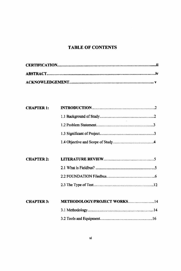
TABLE OF CONTENTS
CERTIFICATION .............................................................................. ii
ABSTRACT ...... ~~ ................................................ ._ .. ._ ................................ ...... iv
ACKNOWLEDGEMENT .................................................................. v
CHAPTER!: INTRODUCTION ................................................. 2
1.1 Background of Study ........................................... 2
1.2 Problem Statement ............................................. 3
L3 Signiftcant of Project .......................................... 3
1.4 Objective and Scope of Study ............................... .4
CHAPTER2: I.ITE~TURE RE~~ ....................................... 5
2.1 What is FieldbuJ>? ............................................................. 5
2.2 FOUNDATION Filedbus ...................................... 6
2.3 The Type of'Test ............................................... l2
CHAPTER3: METHODOI.OGY/PROJECT ~ORKS ..................... l4
3.1 Methodology ................................................... .14
3.2 Tools and Equipment.. ....................................... 16
vi
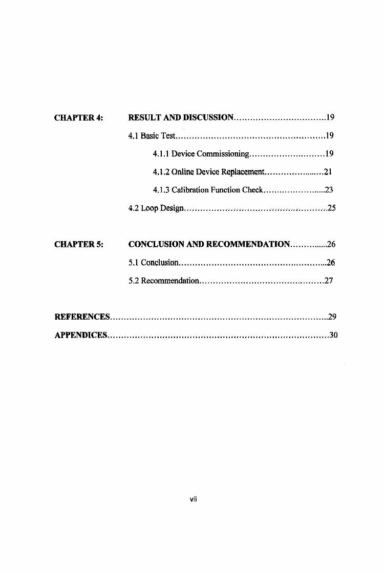
CHAPTER4: RESULT AND DISCUSSION ................................. .19
4.1 Basic Test ........................... ~ ............................ 19
4.1.1 Device Commissioning ............................ l9
4.1.2 Online Device R~placement ....................... 21
4.1.3 Calibration Function Check ........................ 23
4.2 Loop Design .................................................... -.. 25
CHAPTERS: CONCLUSION AND RECOMMENDATION ............... 26
5.1 Conclusion ....................................................... 26
5.2 Recommendation .............................................. 27
REFERENCES ................................................................................ 29
APPENDICES .•...••... .- ...•......•...•.•......... .-.- .......•..............•.....• .-.- .. -....•• .- ..• 30
vii
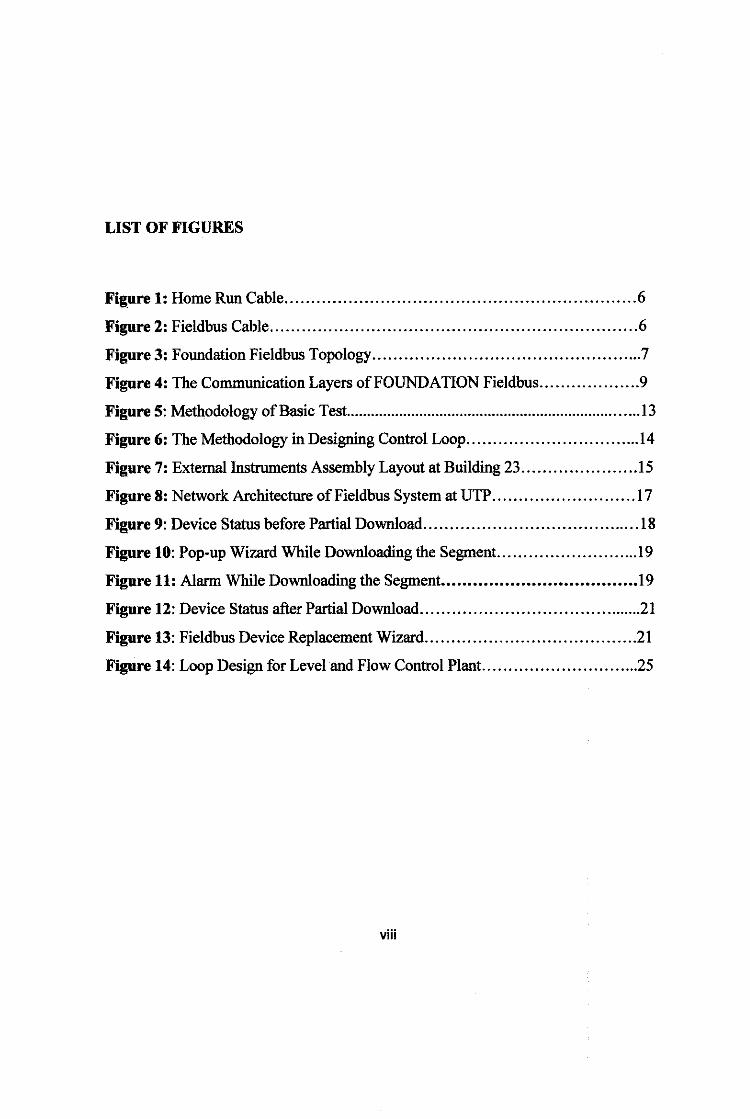
LIST OF FIGURES
Figure 1: Home Run Cable .................................................................. 6
Figure 2: Fieldbus Cable ..................................................................... 6
Figure 3: Foundation Fieldbus Topology ................................................... 7
Figure 4: The Communication Layers of FOUNDATION Fieldbus ................... 9
Figure 5: Methodology of Basic Test ........................................................................ 13
Figure 6: The Methodology in Designing Control Loop ................................. 14
Figure 7: External Instrmnents Assembly Layout at Building 23 ..................... .15
Figure 8: Network Architecture of Fieldbus System at UTP ........................... 17
Figure 9: Device Status before Partial Download ......................................... 18
Figure 10: Pop-up Wizard While Downloading the Segment .......................... .19
Figure 11: Alarm While Downloading the Segment •••...•••...•••.••••••••.••••.••••••• 19
Figure 12: Device Status after Partial Download ........................................... 21
Figure 13: Fieldbus Device Replacement Wizard ........................................ 21
Figure 14: Loop Design for Level and Flow Control Plant .............................. 25
viii
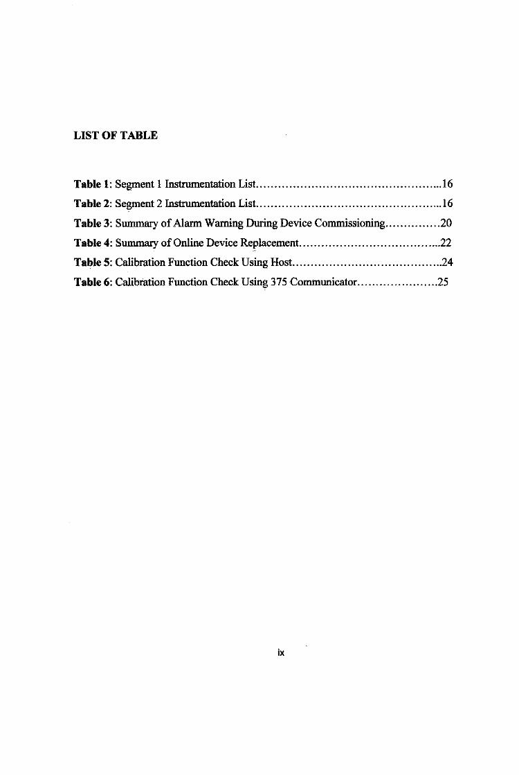
LIST OF TABLE
Table 1: Segment 1 Instrumentation List .................................................. .16
Table 2: Segment 2 Instrumentation List. ................................................. .16
Table 3: Summary of Alarm Warning During Device Commissioning ............... 20
Table 4: Summary of Online Device Replacement ....................................... 22
Table 5: Calibration Function Check Using Host ......................................... 24
Table 6: Calibration Function Check Using 375 Communicator. ..................... 25
ix
1.1 Batkground ofStudy
CHAPTER I
INTRODUCTION
In a process control system, 4-20 mA technology is widely used which
needs each device connects to computer control via its own cable and
communication point at the controller level. In this recent year, Fieldbus
technology has emerged and will be replacing the previous 4-20 mA technology.
Fieldbus is an industrial network system for real-time distributed control which
used microprocessor based cnntrol. It is two ways multi-drop communication
among the intelligent and control devices and automation and display system. The
idea of fillldbus was pf9POSlld ro solve problllms such as proprietary protocols,
slow transmission rate and different data formats. With Fieldbus technology,
various devices from different manufacturers and vendors. can communicate. via
the same language.
Thus, the need of Interoperability Testing is to ensure that the end used will
m>t fac.ed any difficulties or problem regarding to communication between devices.
from various manufacturer/ vendor such as Emerson, Y okogawa, Honeywell or
Foxboro. This project also aims to provide a simple loop design using EMERSON
configuration for brief familiarization to the fieldbus system for scientific
researchers and engineers, as foundation for further development for either
laboratory or industrial applications and testing. Because of several tests need to
be carried out, Foundation Fieldbus system have been installed in Universiti
Teknologi Petronas (UTP) process lab. All testing and maintenance of the system
will be. performed in UTP (together with vendors, contractors and SKG 14 team
projects). All FFTF equipment confirms to IEC 801, EN 50081-2 and EN 50083-
2. requirements for Electromagnetic Compatibility (EMC) [1]·[2] [3].
1
1.2 Problem Statement
The interoperability of FOUNDATION Fieldbus is a communication
between different devices to host from several manufacturers or vendors. Fieldbus
technology is claimed to be interoperability and can replaced the recent 4-20 mA
technology [8]. Furthermore since the main ol!jective of fieldbus technology is to
overcome the problem in current computer connection in term of the slow speed
of transmission rate, propriety protocol and data format, several testing need to be
done to ensure the real performance of this system. The design loop will be
introduced in this project that might be beneficial to author to understand the
whole system and also beneficial for further research.
The outcome of the tests will become the reference to the production of a
PETRONAS approved list for FOUNDATION Fieldbus system and field devices.
This will involve verification of open standard using several tests
1.3 Significance ofProjeet
Upon completion of the research and testing, the fmal results would be used
as reference in formulating test procedures and standard for implementation in
PETRONAS Group-wide. The testing and catcutation wilt determine the
performance of the Foundation Fieldbus system.
This project is a continuation of previous testing and performance evaluation
on the Fieldbus Interoperability Test (FFIT). However, for this project, new
design loop will be introduced and tried. A comprehensive technical report on the
FFIT will be the outcome of this project.
2
1.4 Objective and Scope of Study
Objective
I. To assist the SKG 14 in developing the test methodology (on StressTest
the second testing). The scope of testing will cover the interoperability
test using the EMERSON's host.
2. To design a new loop system for better understanding of the project and
might be beneficial for further research.
3. To monitor and discuss the system performance and issues especially the
communication between devices and host.
Scope of Study
The seeking of understanding on FOUNDATION Fieldbus must first be achieved
in completing this project. The scope of study consists of:
1. The detail approach in designing, configuring and implementing a
fieldbus test rig from the various loose field devices, controllers and
actuators, and the software development tool.
2. The familiarization with vendor Distributed Control System (DCS)
especially on EMERSON Delta V System.
3. The study on Basic lnteroperability Testing and its methodology which
consist of Stress test and Diagnostic test.
3
CHAPTER2
LITERATURE REVIEW
2.1 What is Fieldbus?
Fieldbus is an industrial network system for real-time distributed control
which used microprocessor based rontr~. It is digital, bi-directional, multi-drop,
serial-bus, communications to link isolated field devices, such as controllers,
transducers, actuat{li'S and sen8{)1'8. The Fieldbus teclmoiDgy is a data resoorce that
can provide maintenance information for field instrmnents on-line [7]. This
information Qlpability QIR assist the maintenance wmk and reduce the costs.
Fieldbus is actually a technique to connect instrmnents in a manufacturing
plant and replacing the previous -computer connection by which ooly 2 devices
could communicate at a certain time. This would be equivalent to a current widely
used 4-20 mA communication scheme that needs each device connects to
computer control via its own cable and communication point at the controller
level. However, the Fieklbus connection is equivalent to rurrent Local Area
Network (LAN) connections, which mean it requires only one communication
path for hundreds m analogue and digital devices. Thus, all devices QIR be
connected at the same time via the same port connection which means fieldbus
connection reduces both the length m the Qlb)e required and the nwnber m Qlbles
required[6][8].
Each field device has low cost computing power installed in it, making each
device a 'smart' device. Each device will be able to execute simple functions on
its own such as diagnostic, control, and maintenance functions as well as
providing bi-directional communication capabilities. With these devices not only
will the engineer be able to access the field devices, but they are also able to
communicate with other field devices J5].
4
2.2 FOUNDATION Fieldbus
Unlike proprietary network protocols, FOuNDATiON fieldbus is neither
owned by any individual company, nor regulated by a single nation or standards
body. The technology is controlled by the Fieldbus Foundation, a not-for-profit
organization consisting of more than 100 of the world's leading controls and
instrumentation suppliers and end users. ( 5]
FOUNDATION fieldbus retains many of the desirable features of the 4-20
rnA analog system, such as a standardized physical interface to the wire, bus
.powered devices on a single wire, and intrinsic safety options, it offers a host .of
additional benefits to users.
In FOUNDATION Fieldbus, there are two related implementations of have
been introduced. These two implementations use different physical media and
communication speeds to meets with the process control environment needs.
• HI works at 3 L25 Kbps and generally connects to field devius, It
provides communication and power over standard twisted-pair wiring. HI
is currently the most common implementation (5].
• Ethernet works at 100 Mbps and generally connects input/output
subsystems, host systems, linking .dev:ices, gateways, .and field .devices
using standard Ethernet cabling. It doesn't currently provide power over
the cable, although work is !lllder way to address this [5].
5
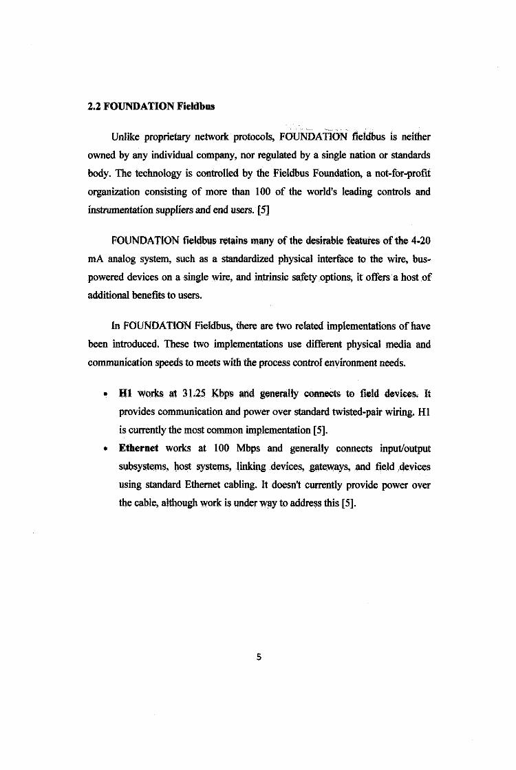
Figures below show the difference between home run cables (usually 4-20 rnA) to
Fieldbus.
CONTROL ROOM
Home-run cable
JlllhCtlon Box
Figure 1: Home Run Cable [5]
Hl r::"::=:ofieldbus CONTROL f---. ROOM
Hl ~ldbus
Figure 2: Fieldbus Cable [5]
The above figures show the different of the length and amount of cable used
by current system and fieldbus system. FOUNDATION Fieldbus' use of existing
wiring and multi-drop connections provides significant savings in network
installation costs. This includes reductions in intrinsic safety barrier termination
and cable costs, particularly in areas where wiring is already in place.
6
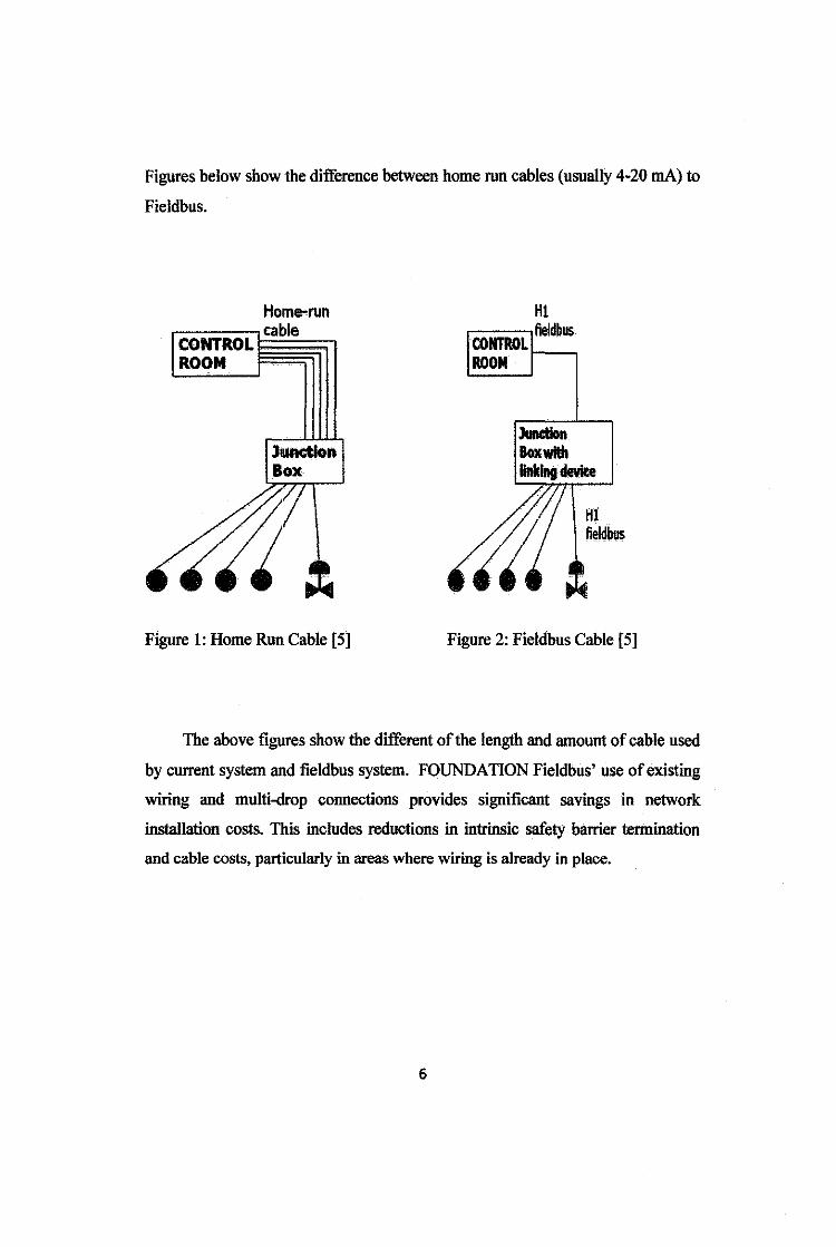
Figure below shows the FOUNDATION Fieldbus topology. On top of the
hierarchy, there is Human Machine Interface (HMI) where an operator can
monitor or operate the system. Hubs and switches provide a means to connect
multiple nodes. Hubs serve as a connection point and rejuvenate the electrical
signal as messages are forwarded on the control network.
HMI is typically linked to a middle layer of programmable logic controllers
(PLC) via a non time critical communications system (e.g. Ethernet). At the
bottom of the control chain is the fieldbus which links the PLCs to the
components which actually do the work such as sensors, actuators, electric
motors, console lights, switches, valves and contactors.
Trunk
Field ~Devices
Pigure 3: FOUNDA'TION Fieldbus Topology [2]
7
Furthennore, FOUNDATION Fieldbus will also improve safety by
providing operators with earlier notification and warning of pending and current
hazardous conditions. Since process production plant plants are heterogeneous
and complex in many aspects such as long cables distributed across buildings and
floors also many different types of instrument such as transmitter and sensors,
limiting the amount of energy in explosion hazardous area is crucial [2] [9].
Process production plants are heterogeneous and complex in many respects
where field devices of very different types are mounted alongside conventional
motors and simple digital sensors. Sites place requirements for long cable lengths
distributed across buildings and floors, with installation in safe and explosion
hazardous areas with their stringent safety regulations. In short, a typical plant
layout consists of practically any type of application, and this has to be taken into
consideration when designing and installing fieldbus systems. To validate the
overall intrinsic safety it is required to compile all field devices' and cables'
safety parameters, and match them against the power source. In the beginning this
effort and the very low amount of energy initially available prohibited application
of fieldbus in hazardous areas. Today the market is able to look back on a
respectable and rapid development of intrinsically safe fieldbus implementation
[2].
• Fieldbus Concept (HI Concept)
Since we shall be using the Hl in the project, the study was mainly done for the
Hl concept only. There are six conceptual parts to a Fieldbus network: links,
devices, blocks and parameters, linkages, loops, and schedules.
• Four Fieldbus Layers
FOUNDATION Fieldbus communication layers consists of the physical layer, the
communication stack, and the user layer.
8
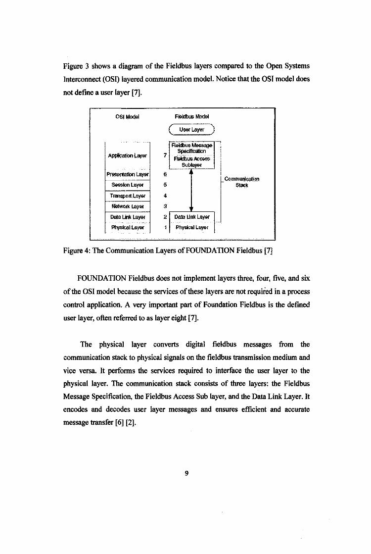
Figure 3 shows a diagram of the Fieldbus layers compared to the Open Systems
Interconnect (OSI) layered communication model. Notice that the OSI model does
not define a user layer [7].
OSI M<l<l&l
APP!i<;!'!iQn ~
Pr1l$9ftllll!>n L-
:i'~ionlay9r
TransportL-
Nl>lwt<l< L<tyl>r
Dala Lblll l.<r)<>r ··.·
Physir-.al L&Y"r
7
6
5
4
3
2
1
F~Mod<>l
( UMr L.ay&r )
Roldbuo~ $pQcilicaliOO
Fl&ldbcts -"'""*" Scrbkiol"'r
Da1lt Unk LOY"r
!>hysical L"Y"I
C.C.11~mtmi~!on S!;il&k
Figure 4: The Communication Layers of FOUNDATION Fieldbus [7]
FOUNDATION Fieldbus does not implement layers three, four, five, and six
of the OSI model because the services of these layers are not required in a process
control application. A very important part of Foundation Fieldbus is the defined
user layer, often referred to as layer eight [7].
The physical layer converts digital fieldbus messages from the
communication stack to physical signals on the fieldbus transmission medium and
vice versa. It performs the services required to interface the user layer to the
physical layer. The communication stack consists of three layers: the Fieldbus
Message Specification, the Fieldbus Access Sub layer, and the Data Link Layer. It
encodes and decodes user layer messages and ensures efficient and accurate
message transfer [ 6] [2].
9
The Data Link Layer manages access to the fieldbus through the Link
Active Scheduler by splitting data into frames to send on the physical layer,
receiving acknowledgment frames, and re-transmitting frames if they are not
received correctly. It also performs error checking to maintain a sound virtual
channel to the next layer. The Fieldbus Access Sub layer provides an interface
between the Data Link Layer and the Fieldbus Message Specification layer.
Within the Fieldbus Messaging Specification layer are two management layers
called System Management and Network Management. System Management
assigns addresses and physical device tags, maintains the function block schedule
for the function blocks in that device, and distributes application time. The device
can be located through System management [10]
The user layer provides the interface for user interaction with the system. It
uses the device description to tell the host system about device capabilities. It
defines blocks and objects that represent the functions and data available in a
device. Rather than interfacing to a device through a set of commands, like most
communication protocols, FOUNDATION Fieldbus lets user interacts with
devices through a set of blocks and objects that defme device capabilities in a
standardized way. The user layer for one device consists of the resource block,
and one or more transducer blocks and function blocks [3] [2]
A key objective for Foundation Fieldbus is interoperability, the ability to
build systems comprised of devices from a variety of manufacturers. Instead of
requiring that device manufacturers use only a given set of functious in a device to
ensure that a system can always communicate with a new device, Foundation
Fieldbus uses device descriptions, which describe all the functions in a device.
They allow manufacturers to add features beyond the standard Foundation
Fieldbus interface without fearing loss of interopembility [8] [7].
10
2.3 The Type of Tests
Fieldbus technology is one of process application that widely used in
process control application. It is a digital, two ways, multi drop communication
mechanism that will connect host systems, field devices and other automation
systems on a network [1]. Fieldbus is the equivalent of the current LAN type
connections, which require only one communication at the controller level and
allow multiple of analog and digital points to be connected at the same time thus
reducing both the length of the cable required, and the number of cables required
[2]. The testing for the FOUNDATION Fieldbus consists of two main tests, the
reliability test and the interoperability test [I].
• The Basic lnJeroperability Test
The reliability test consists of three tests. The Basic Interoperability test
which perform during the device commissioning. The test should show the effect
of the device beforehand, the interoperability between different host and field
device, the online device replacement, the bus health inspection and the device
fmnware upgrade [3].
• Stress Test
The second test is the Stress Test. This test should involve the fully loaded
segment which confmn the maximum number of devices that could be used, the
power failure recovery, communication integrity soak test, back up of LAS (Link
Active Scheduler), the control in field and the test of maximum cable length and
different cable type [3].
11
• Diagnostic
The third test is the diagnostic capability which involves the verification
operation of advance function blocks, the device health check, the verification
interoperability between different vendor devices and host and the ease of
calibration check and trims [4].
• Full Interoperability Test
The other main test which is the interoperability test involves the host
communication test and the full system test. The host communication test will
check only the control system from the m interface cards to the operator
workstations without connecting all the field instrument devices. A single field
instrument device will connect to the m interfaces one by one and check the basic
communication between a device and the interface. The full system test will
verilY the system hardware and configuration data downloaded to the field
devices. This approach has the benefit that all control functions, including the
field devices, are checked and problems solved before arrival at site [5].
12
CHAPTER3
METH6DOLGY I PROJECT WOR:K
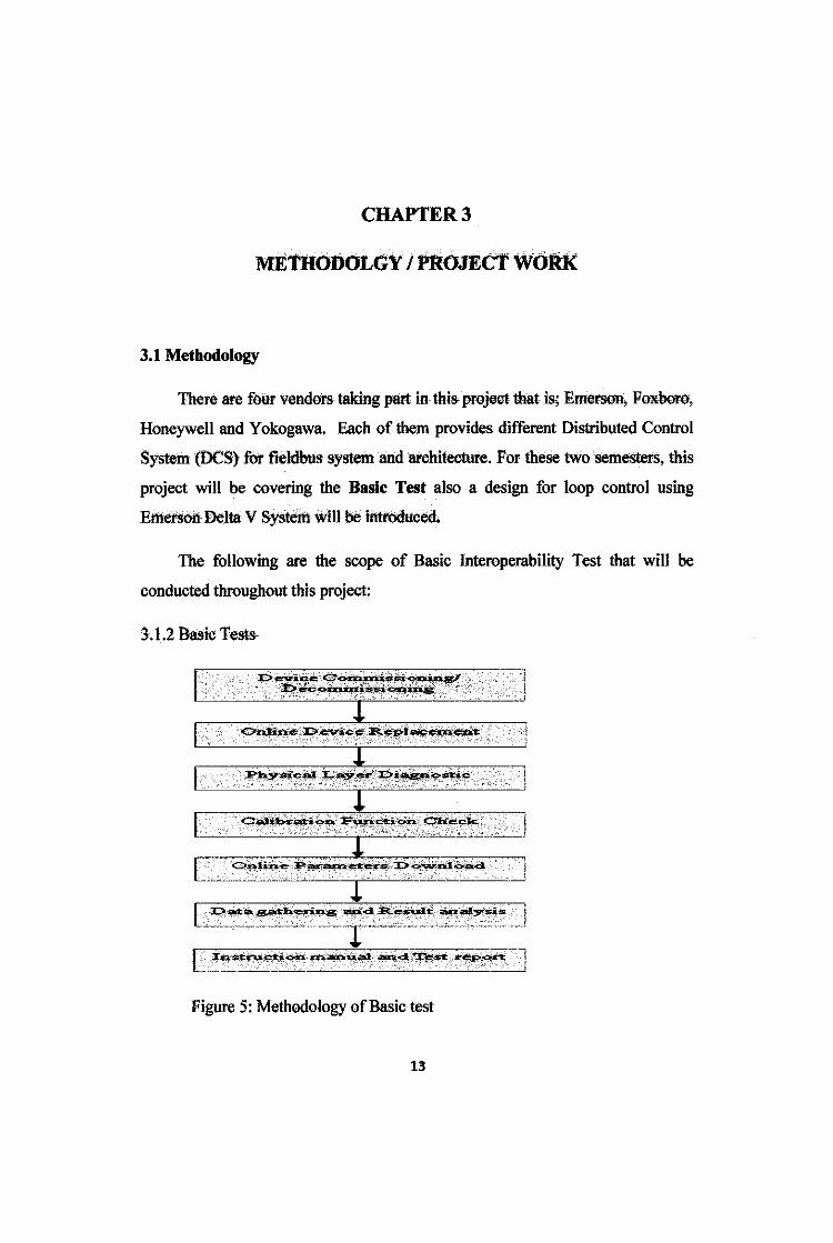
3.1 Methodology
There are four vendor& taking part in this- pl{)ject that i&; Emet"SOn, Poxbor{),
Honeywell and Yokogawa. Each of them provides different Distributed Control
System (DCS) for fieldbus system and architecture. For the&e tWo semesters, this
project will be covering the Basic Test also a design for loop control using
Emerson Delta v System will be inti"Odueed.
The following are the scope of Basic 111teroperability Test that will be
conducted throughout this project:
3.1.2 Basic Tests
[ [
J:?~i~~·::~~~~:-~~ - -:r>.l='JP'~-~~-oq.a...s~
1 ----i
I l
L ~ata:g;M;h'~*~-, ~-d, ~:e~J,t:_ -~-~Y~~- .... 1 ·-·----··-·-·---·- ----1""--------- "''''"''''"'- --- -L I0.$1:lru.~i()o.h -~ia[b:~;l;llt- --~ 'tt':~~ ~<>rt
Figure 5: Methodology of Basic test
13
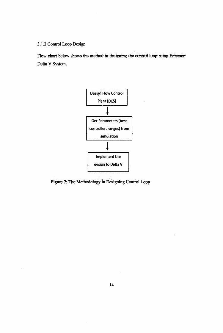
3 .1.2 Control Loop Design
Flow chart below shows the method in designing the control loop using Emerson
Delta V System.
Design Flow Control
Plant (DCS)
Get Parameters (best
controller, ranges) from
simulation
Implement the
design to Delta V
FigUre 7: The Methodology in Designing Control Loop
14
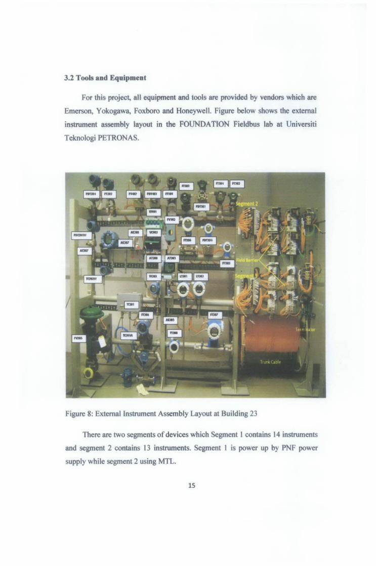
3.2 Tools and Equipment
For this project, all equipment and tools are provided by vendors which are
Emerson, Yokogawa, Foxboro and Honeywell. Figure below shows the external
instrument assembly layout in the FOUNDATION Fieldbus lab at Universiti
Teknologi PETRONAS.
Figure 8: External Instrument Assembly Layout at Building 23
There are two segments of devices which Segment 1 contains 14 instruments
and segment 2 contains 13 instruments. Segment l is power up by PNF power
supply while segment 2 using MTL.
15
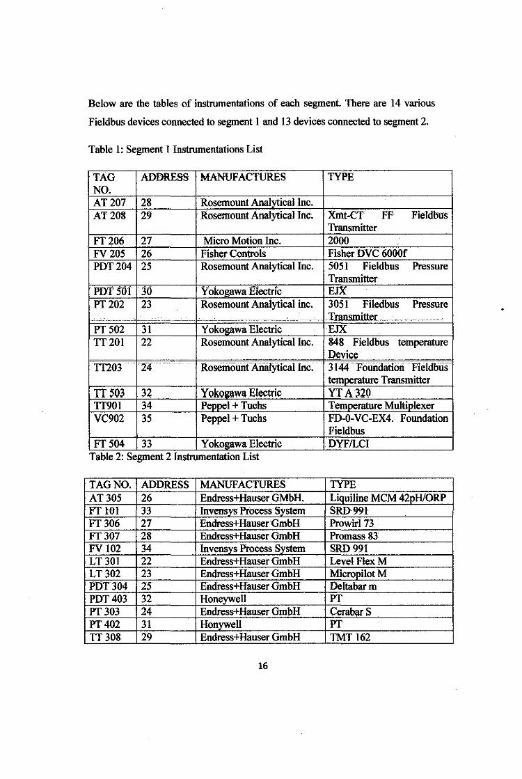
Below are the tables of instrumentations of each segment There are 14 various
Fieldbus devices connected to segment I and 13 devices connected to segment 2.
Table 1: Segment I Instrumentations List
TAG ADDRESS MANUFACTURES TYPE NO. AT207 28 Rosemount Analytical Inc. AT208 29 Rosemount Analytical Inc~ Xmt-CT FF Fieldbus
Transmitter FT206 27 Micro Motion Inc. 2000 FV205 26 Fisher Controls Fisher DVC 6000f PDT204 25 Rosemount Analytical Inc. 5051 Fieldbus Pressure
Transmitter PDT SOt 30 Yokogawa Electric EJX PT202 23 Rosemount Analytical inc. 3051 Filedbus Pressure
__ , __ . ----- ..:; . ·'·-·· - .. -·--- -'-- --- ---·-·· .... .. -- --------- _Transmitter ... . ....
PT502 31 Yokogawa Electric EJX TT201 22 Rosemount Analytical Inc. 848 Fieldbus temperature
---------··-~ ... -- -- ····--·---.. -- ................ ,. ____ Device ·---··--····- ...................... _ ..
TT203 . 24 RoseriioUIIt Anal)'tical Inc . 3144 Folllldation Fieldblls . temperature Transmitter
TIS03 32 Yokogawa Electric YT A320 TT90l 34 Peppel + Tuchs Temperature Multiplexer VC902 35 Peppel + Tuchs FD-O-VC-EX4. Foundation
Fieldbus FT504 33 Y okogawa Electric DYFILCI .
Table 2: Segment 2 Instrumentation Ltst
TAG NO. ADDRESS MANUFACTURES TYPE AT305 26 Endress+Hauser GMbH. Liquiline MCM 42pH!ORP FT 101 3-3 Invensys Process System SID991 FT306 27 Endress+Hauser GmbH Prowirl73 FT307 28 Endress+Hauser GmbH Promass 83 FV 102 34 Invensys Process System SRD991 LT301 22 Endress+Hauser GmbH LevelFlexM LT302 23 Endress+Hauser GmbH Micropilot M PDTJ04 25 Endress+Hauser GmbH Deltabarm PDT403 32 Honeywell PT PT303 24 Endress+Hauser GmbH Cerabar s PT402 31 Honywell PT TT308 29 Endress+Hauser GmbH TMT 162
16
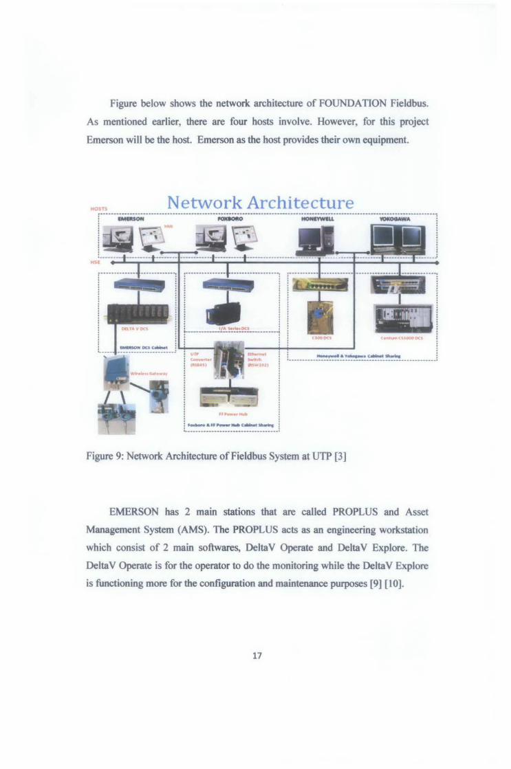
Figure below shows the network architecture of FOUNDATION Fieldbus.
As mentioned earlier, there are four hosts involve. However, for this project
Emerson will be the host. Emerson as the host provides their own equipment.
Network Architecture
. ,..-L~~.~-~-~~-~-
Figure 9: Network Architecture of Fieldbus System at UTP [3]
EMERSON has 2 main stations that are called PROPLUS and Asset
Management System (AMS). The PROPLUS acts as an engineering workstation
which consist of 2 main softwares, Delta V Operate and Delta V Explore. The
Delta V Operate is for the operator to do the monitoring while the Delta V Explore
is functioning more for the configuration and maintenance purposes [9] [1 0].
17
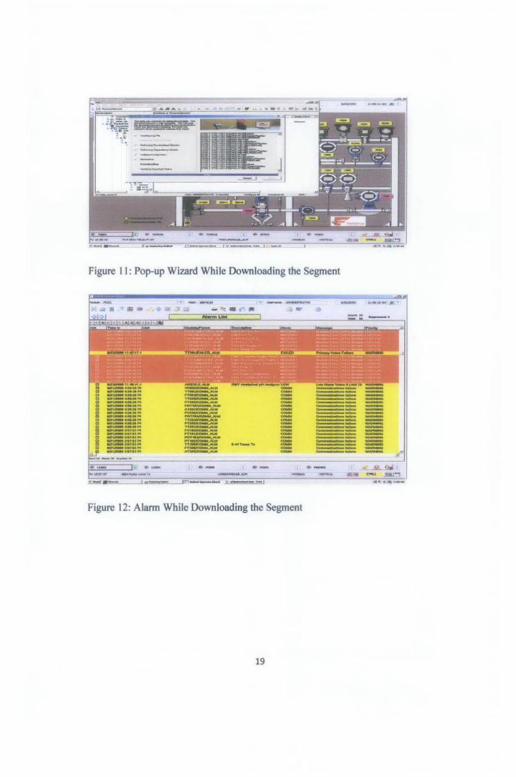
Figure 11 : Pop-up Wizard While Downloading the Segment
u»u-L T
--------------------------c;;;;;;;;;;o;;;=
.....
Figure 12: Alarm While Downloading the Segment
19
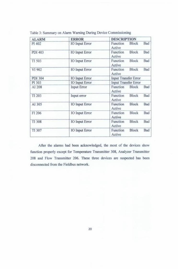
Table 3: Summary on Alarm Warning During Device Commissioning
ALARM ERROR DESCRIPTION PI402 10 Input Error Function Block Bad
Active PDI 403 10 Input Error Function Block Bad
Active TI 503 10 Input Error Function Block Bad
Active VI902 10 Input Error Function Block Bad
Active PDI 304 10 Input Error Input Transfer Error PI 303 10 Input Error Input Transfer Error AI 208 Input Error Function Block Bad
Active TI203 Input error Function Block Bad
Active AI 305 10 Input Error Function Block Bad
Active FI206 10 Input Error Function Block Bad
Active Tl308 10 Input Error Function Block Bad
Active TI 307 10 Input Error Function Block Bad
Active
After the alarms had been acknowledged, the most of the devices show
function properly except for Temperature Transmitter 308, Analyzer Transmitter
208 and Flow Transmitter 206. These three devices are suspected has been
disconnected from the Fieldbus network.
20
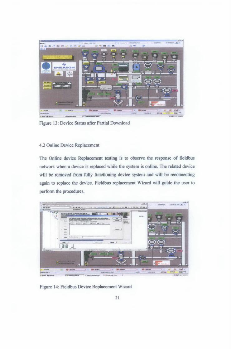
Figure 13: Device Status after Partial Download
4.2 Online Device Replacement
The Online device Replacement testing is to observe the response of fieldbus
network when a device is replaced while the system is online. The related device
will be removed from fully functioning device system and will be reconnecting
again to replace the device. Fieldbus replacement Wizard will guide the user to
perfonn the procedures .
., S:."'i:..":!.e.=:;:=--=t.-==-.-:-=- r ~ 1 - ... _._______ - _j
1
- !_h .. }4i.+iiio !-e I
., - _ _ .J -- - - r ---
Figure 14: Fieldbus Device Replacement Wizard
21
CHAPTER4
RESULT AND DISCUSSION
4.0 Basic Test
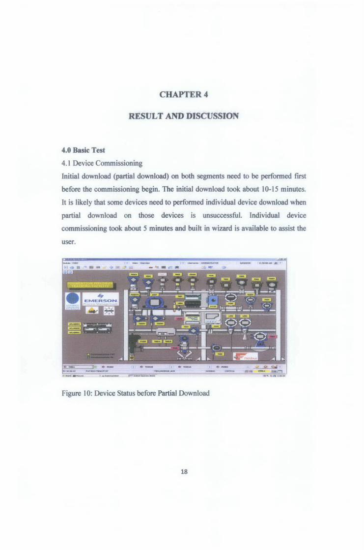
4.1 Device Commissioning
Initial download (partial download) on both segments need to be perfonned first
before the commissioning begin. The initial download took about 10-15 minutes.
It is likely that some devices need to perfonned individual device download when
partial download on those devices is unsuccessful. Individual device
commissioning took about 5 minutes and built in wizard is available to assist the
user.
Figure 10: Device Status before Partial Download
18
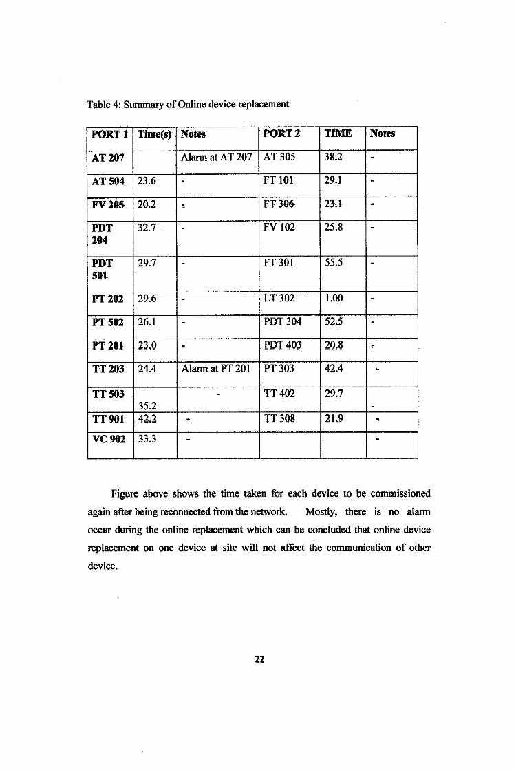
Table 4: Summary of Online device replacement
PORT! Time(s) Notes PORTZ TIME Notes
AT207 Alarm at AT 207 AT305 38.2 -AT504 23.6 - FT 101 29.1 -FV205 20.2 - FT306 23.1 -PDT 32.7 - FV 102 25.8 -204
PDT 29.7 - FT301 55.5 -501
PT202 29.6 - LT302 1.00 -PT502 26.1 - PDT304 52.5 -PT201 23.0 " PDT403 20.8 -TT203 24.4 Alarm at PT 201 PT303 42.4 -TT503 - TT402 29.7
35.2 -TT901 42.2 . TT308 21.9 -VC902 33.3 - -
Figure above shows the time taken for each device to be commissioned
again after being reconnected from the network. Mostly, there is no alarm
occur during the online replacement which can be concluded that online device
replacement on one device at site will not affect the communication of other
device.
22
However, when AT 207 is being replaced, there is alarm occur and online
replacement at this device cannot be perfonned successfully. There is also alarm
occur at PT 20 I when TI 203 is replaced. This might caused by the cable conflict
bus, this alarm does not affect the device perfonnance.
4.3 Calibration Function Check
Fieldbus device range value can be changed while in OUt Of Service (OOS)
mode. For basic test purposes, the parameter download is limited to change the
range of the device uslrtg Host and 37j HART IFF Commooicatot. Rescale Cliilfiot
be perfonned using Emerson AMS(iAMS)Asset Management System.
Summary Method:
1. Change the mode of respective device to OOS.
2. Change the range XD_scale and OUT_scale
3. Cliange back the mode to Auro. Record the response
4. Repeat the steps using 375 Communicator.
4.3.1 Using Host
The range of XD_scale and our_ scale are edited at Control Studio, The
Auto mode is changed to OOS at AI Block. When the mode is changed back to
Auto, the new value of range is updated automatically by tile device.
23
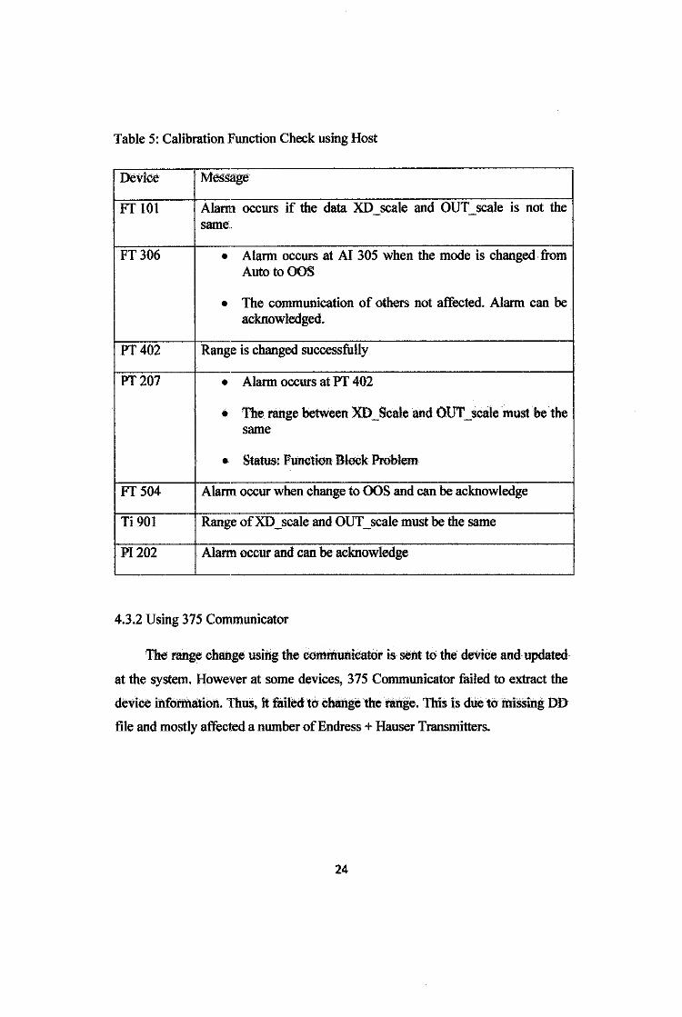
Table 5: Calibration Function Check using Host
Device Message
FT 101 Alarm occurs if the data XD_scale and OUT_scale is not the same ..
FT306 • Alarm occurs at AI 305 when the mode is changed from AutotoOOS
• The communication of others not affected. Alarm can be acknowledged.
PT402 Range is changed successfully
PT207 • Alann occurs at PT 402
• The range between XD_Scale and OUT_scale mustbe the same
• Status: Function Bleck Problem,
FT504 Alarm occur when change to OOS and can be acknowledge
Ti 901 Range ofXD _scale and OUT _scale must be the same
PI 202 Alarm occur and can be acknowledge
4.3.2 Using 375 Communicator
The range change using the commutticater is sent to the device and updated
at the system. However at some devices, 375 Communicator tailed to extract the
deviee iitfotmalion. ThuS, it failed to change the range. This is due to missing DD
file and mostly affected a number of Endress + Hauser Transmitters.
24
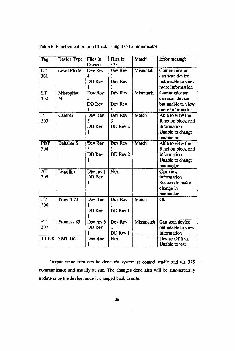
Table 6: Function calibration Check Using 375 Communicator
Tag Device Type File:> In Files in Match Error message Device 375
LT Level FlixM DevRev DevRev Mismatch Communicator 301 4 3 can scan device
DDRev DevRev but unable to view I 3 more information
LT Mictopilof DevRev DevRev Mismatch Comrttunicatot 302 M 5 3 can scan device
DDRev DevRev but unable to view I 3 more information
PT Care bar DevRev DevRev Match Able to view the 303 5 5 function block and
DDRev DDRev2 information I Unable to change
parameter PDT Deltabar S DevRev DevRev Match Able to view the 304 5 5 function block and
DDRev DDRev2 information I Unable to change
parameter AT l,iquillin l)ev rev 1 NIA C:an view 305 DDRev information
I Success to make change in parameter
FT Prowi1173 DevRev DevRev Match Ok 306 I I
DDRev DDRev I I
FT Promass 83 Devrev 3 DevRev Missmatch Can scan device 307 DDRev 2 but unable to view
I DDRev I information TT308 TMT I62 DevRev N/A Device Offline.
I Unable to test
Output range tJim can be done via system at control studio and via 375
communicator and usually at site. The changes done also will be automatically
update once the device mode is changed back to auto.
25
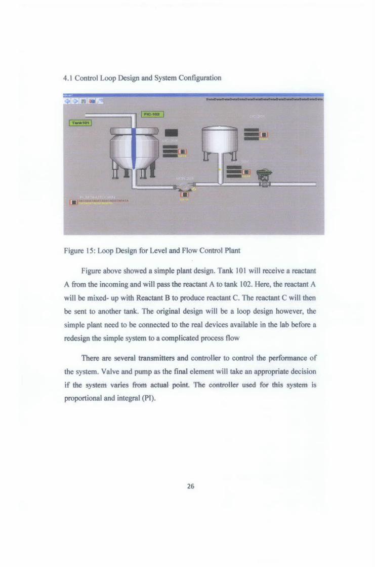
4.1 Control Loop Design and System Configuration
... .,. •• ••• a
Figure 15: Loop Design for Level and Flow Control Plant
Figure above showed a simple plant design. Tank 101 will receive a reactant
A from the incoming and will pass the reactant A to tank 102. Here, the reactant A
will be mixed- up with Reactant B to produce reactant C. The reactant C will then
be sent to another tank. The original design will be a loop design however, the
simple plant need to be connected to the real devices available in the lab before a
redesign the simple system to a complicated process flow
There are several transmitters and controller to control the performance of
the system. Valve and pump as the final element will take an appropriate decision
if the system varies frmn actual point The controller used for this system is
proportional and integral (PI).
26
CHAPTERS
CONCLUSION
5.1 Conclusion
The basic test which is the first test of Foundation Fieldbus Interoperability
Testing has been completed within the range of time. The virtual plant also has
been designed using Delta V system.
As conclusion, upon completing this project, a comprehensive technical
report on the Foundation Fieldbus Interoperability Testing (FFIT) will be emerged
after carrying out an intensive testing and research of the Foundation Fieldbus
system. Generally, two main testing will be done which are the stress test and
diagnostic capability test. A control loop design will be implemented on Delta V
for better understanding on system and its configuration and for further
researches.
The main outputs of this project are:
1. Perform basic test which including Device Commissioning, Online Device
Replacement and Calibration Function Check.
2. Design a control loop using Delta V software. The objective is to model
the plant using Delta V and implement on the real device. However due to
some limitation of the system capability that Delta V only allow certain
function, the real plant implementation cannot be conducted.
27
REFERENCES
[1] PETRONAS E-Learnlng Modules 3 (Plant Monitoring Control System)
and Modules 4 (Process Control Theory)
[2]Foundation Fieldbus Interoperability Testing- Terms of Reference, SKG
14, PETRONAS.
[3] Hisashi Sato, Journal of 'The Recent Movement of FOUNDATION
Fieldbus Engineering', SICE Annual Conference in Fukui, August 4-6,
2003
[4]Teohnical Support and Professional Services, National Instruments, May
2003 Edition.
[5] Fieldbus Org, Citing Internet source URL http://www.fieldbus.org
[ 6] FOUNDATION Fieldbus , Citing Internet sources
URL http://www .foundationfieldbus.com
[7] Emerson, Citing Internet source URL http://www.emerson.com
[8] EMERSON Fieldbus Tutorial Book and manuals
[9]Yologawa, Citing Internet source URL http:// www.yokogawa.com
[lO]William Stallings, ''Data and Computer Communication", Eight Edition:
Pearson Education International Publishing, 2007.
29

APPENDIX
30
Appendii 2
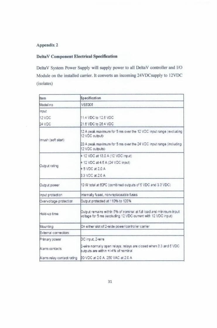
DeltaV Component Eleetrieal Speeifieation
Delta V System Power Supply will supply power to all Delta V controller and 110
Module on the installed carrier. It converts an incoming 24VDCsupply to 12VDC
(isolates)
~em ~pecific.Jtion
r.todel r.o ·.·::xe npu:
12VDC ~ 1-! VOC tot:! e '•JIX
124 vee h 1 6 VDC tc 26 4 \IOC
~2 A puk maxim .. m 'or 5 ms o•~r ~ 12 \IJ: npu: rarl\te {>!:1C :JC 11\t ~2 VDC c.Jtoo .. h
n-u~ :scf: sbrt) ~J A pnk m.1<irn.~m fer 5 ms c.&r r:h& :!4 v:: npu: r•rl\tt (induc1r.~ ~2 •J:C c.JID:~15J
12 V0C at 1~.0 A ( 11 'II[): inJ::.f.)
Ou;:.t ratng 12 VOC at 4 ~f.. ;:!4 VDC ir.pt.t)
+ 5 VOC a: '!.Q A
~.3 vJC l-:~C .:..
Ou;J.pOMr :> W :ctal a: 6JDC ~ccmt :'lid ou;:.r:s c: e VDC .1nd 3 :J VOC}
nou: ~-e:&ct o n:t'Tli'Y \He, nc~.l~a~·~ f.Jsts
pve.:--vc1:a~ pmo:K:.or, pu;..t. prtnctect at ·1~ to 1:c~
Holc-tiot~ Pu;..t. •t1l.l ns .. ~ir 5'h o: r.'lm"'ol l~ f.J lo.1danc r·ir m .. m iro~1 ·c tag~ for 5 ms •elCCiv::li-:g i ~ lfOC wren: flit. 1: VOC "~.J:I
r.tou,tirJ pn t Mer slot of2·wcl& oowt~!:>:lr.hl -.r clrrie•
l=.•el1"'3 cor:lt-~ton Print ;)r'>{ po~=r pc n~at, 2-w•t
~.'.rm CC'l"..JC:S ~·~noll'· a y oren :'!' ay-s: relays are c csed W"l!"l 3 3 ad f VDC p;,t.p ...tts :R wi:l' n +:~~ of nomir a.:
~. a"Tll relay coo:act ra:hg ~J VDC a:! C A Z.SC VA: l~ZC .:..
31

Appendix 3
Delta V Series 2 Serial Card, 2 Ports, RS232/RS485
~ltaV Series 2 Serial Cord, 2 Ports, RS2J2!RS485
-he OelbV Serial Card provides an mterface to a vanety r.l serta, deVJce!> that use the Mo11ous
R~u or ASCI. protocol W~h lhe DeitaV Explorer it is possible to conT;Jure each of the t'"''O oorts
prov•:!ed on :re seral card to sJpport RS232, RS422!ii85 half duole:<. or R$422!485 ful duplex
Signals and you can conflflure :he baud rat~ of each oort. The serla card reQuires a JeltaV Senal
Tennma Block to pllWlde :em1,natJons for Yming.
If the RS422/485 per:s are used, ltle stl•eld must aiso provide !he groond ·eference for the port
Connect the cable shteld :o the correspondi11g QI'OI.illd IG,..O) terminal on the seria: teml!nall:llock
lttnt Spfcifiution I r---
I Mocl!·l VE41l3e?2
N.;~· 'l' iif il j:'OOi Two
Fortt-n:u R3232, RS4~4a5 bl' 004 ~ll RS.:.2~485 f.J clll>ktx :corr~rilt
~,tho! >-!".JV ~~DOief)
ElC"" PO'": s J~t ca y sal.r.eo frc~ ~ sys:~~ a1d !'rom uc., ')'.her
IS0'3:i<:'1 .l'ld •achry :!sted :o :fX '~t'OC . Tnt: polis m..ti: b~701>'"1C'!O "a~
e;otema dt:¥"~
E3~d~ C.on!igwablt wrnl.hli'DtbV ~la'\f" I RS132: 1~ 111 ' 5C ~~ ~
Maxmt..mt call'= l~"lgt'lS R34224c!5 J!J nt :tiiliJ f: J I
L3Ca B.JS CUlT! "f. 1 I: VOC
rom nal}. p~ c.trc 2;lC ,.4 :y~ ~ . ~01) ~A. r.·»·m~m
....-
I F"tela c ~~1pc.-e-·. ~··caro None
1\km'lr~ AssiiJI•::I s!Gt of .c ~!r
32
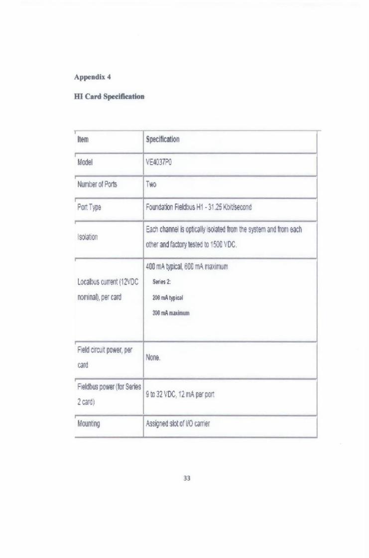
Appendix4
m Card Speei.fkation
r-lt~m Specification
I
Model VE403PO
Nur1ber of Pn TVfO
POii -ype ~ounda:m Fieldl.>us H1 • 31.25 Kbdsecond
lsOiabon Each channel s optcally sdated frQm ttle system and froM each
other and factor; tes~ed to 1500 VDC.
I
400 ntA tiJlical, ~nn mA r1axir1un·
Locan>us current i12VDC Seri~ 2:
nonmal), ~er card 200 mA typic.ll
300 rnA maximum
Peld c:rcu~ power, pe" None.
card
Peldbus power (for Seri&s 9 to 32 VDC, 12 MA per por:
2 card)
. Mount1ng Ass~nen slot or ~o carrer
33
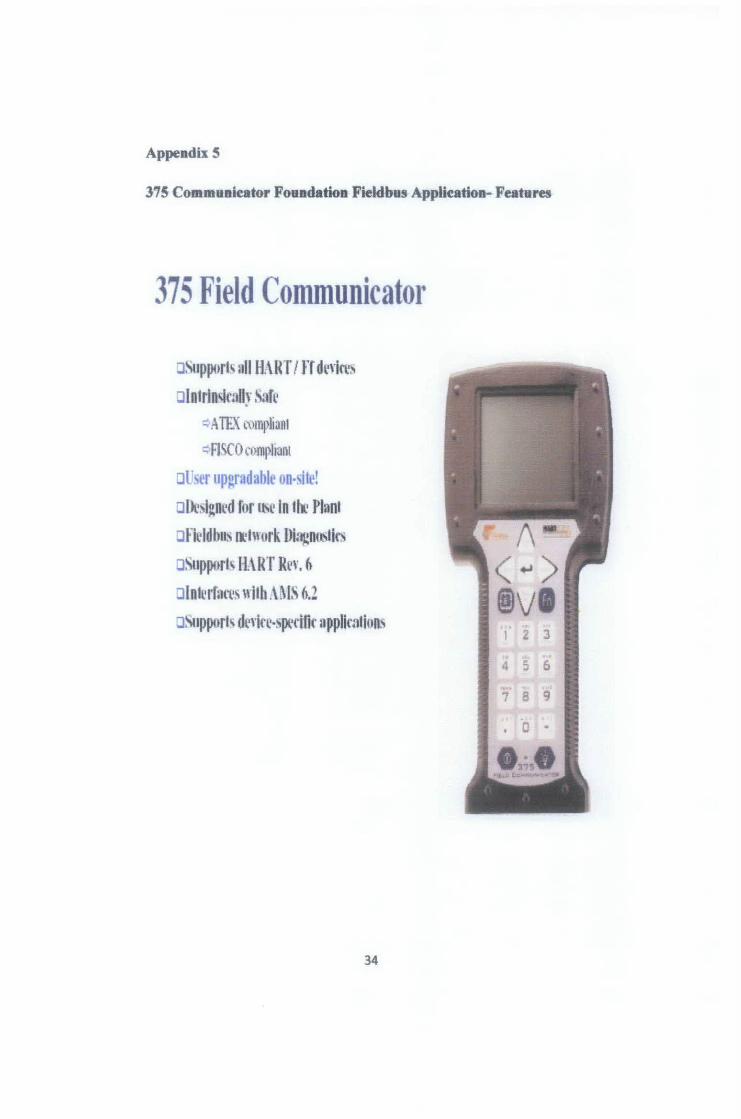
Appendix S
375 Communicator Foundation Field bus Applkation- Features
375 Field Communicator
asupport~ nil H.\ f( T I rr dl·,·in·~ :Jintrln~mn~· ,\afl'
Q_;\ TEX u>mpliant
~FI SCO Ctlmphnnt
ar er upgradable on-,ife!
altt·~I~nl•d f11r ItS~ In 11-.. Plant ol-"il'ldbns ll'ln urk Di~nt~llt~
aSupport~ H.\RT R~,·. (l
aln1l'rfllfl's n ilh .\~1.\ 6.2
osuppurt' dl'\'kl··~pcdfir llpplknJiun'
34
1 2 3
4 5 6
7 B 9
0 •
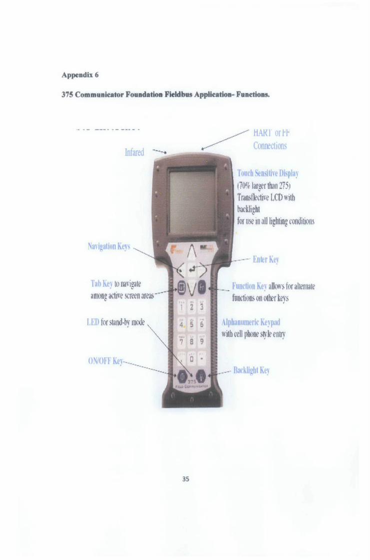
Appendix 6
315 Communicator Foundation Field bus Application- Funetions.
Infared
Na,· igation Kc) s
Tab~ to mwig~te ~
amcmg adive screen areas ''"' 2 3
5 6 8 9
ON/OFI' Ke)·--- 0 •
35
Tl)nl'h "' i'i·· •u ~la) 170r,tr lar~r than275)
~
T ranstl?ctwe LCD w11b backlight tor use 1n all hghting condibons
-- Enter Key
'••'l"t:n, I allows for alternate function~ on otlfr b:y~
'·· 1 · rn •·ir .' r:rd with rell ~hone )tyJe enny
Appendix 7
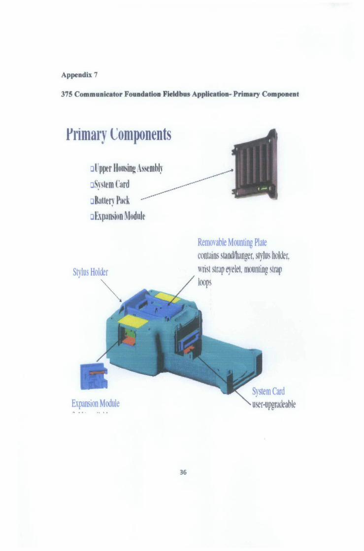
375 Communicator Foundation Fieldbus-AppHeation- Primary Component
l'rimary L:omponents
Jlfppcr llonsing As~~mbJ~· _____..
oS~·,trm tard .---.------J &ttu~ r~u·k .---~ J['f)utt\iun Mudulr
Stylus Holder
~
Expansion Module
36
Removable Mounting Plate contains standllmnger, Sfylus hokler. wri\t stmp eyelet nmuntlng strap loops
System Card user-upgmcleable
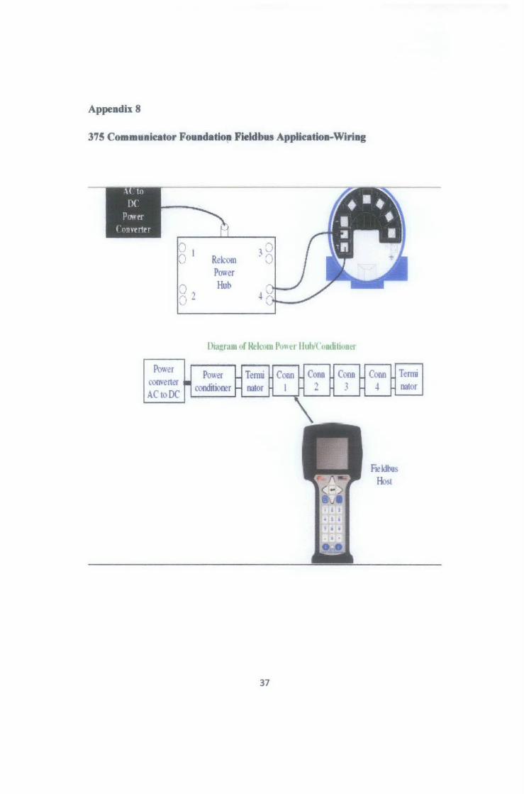
Appendix 8
375 Communieator Fouedation Field bus Applkation-Wiring
D l ,o 'l R~kom ·o ..
PO\\~r
J , Hub ,.... -
Dmgram of l~kom Poncr lluh'l'ondihoncr
Power Termi Po\\er COO\'~ner
ACto DC coo:fuit1rer nator
37
T~rmi
nat or