Embed Size (px)
Citation preview
Tuomo Aho
ELECTROMAGNETIC DESIGN OF A SOLID STEEL ROTOR MOTOR FOR DEMANDING OPERATION ENVIRONMENTS
Thesis for the degree of Doctor of Science (Technology) to be presented with due permission for public examination and criticism in the auditorium 1382 at Lappeenranta University of Technology, Lappeenranta, Finland on the 18th of December, 2007, at noon.
Acta UniversitatisLappeenrantaensis292
LAPPEENRANTAUNIVERSITY OF TECHNOLOGY
Supervisor Professor Juha Pyrhönen
Lappeenranta University of Technology Finland
Reviewers Professor Andreas Binder
Darmstadt University of Technology Germany
Dr. J.R. Bumby
Durham University, School of Engineering United Kingdom Opponent Professor Jorma Luomi Helsinki University of Technology
Finland
ISBN 978-952-214-498-0
ISBN 978-952-214-499-7 (PDF) ISSN 1456-4491
Lappeenrannan teknillinen yliopisto
Digipaino 2007
Abstract Tuomo Aho Electromagnetic Design of a Solid Steel Rotor Motor for Demanding Operation Environments Lappeenranta 2007 147 p. Acta Universitatis Lappeenrantaensis 292 Diss. Lappeenranta University of Technology ISBN 978-952-214-498-0, ISBN 978-952-214-499-7 (PDF) ISSN 1456-4491 The solid-rotor induction motor provides a mechanically and thermally reliable solution for demanding environments where other rotor solutions are prohibited or questionable. Solid rotors, which are manufactured of single pieces of ferromagnetic material, are commonly used in motors in which the rotation speeds exceed substantially the conventional speeds of laminated rotors with squirrel-cage. During the operation of a solid-rotor electrical machine, the rotor core forms a conductor for both the magnetic flux and the electrical current. This causes an increase in the rotor resistance and rotor leakage inductance, which essentially decreases the power factor and the efficiency of the machine. The electromagnetic problems related to the solid-rotor induction motor are mostly associated with the low performance of the rotor. Therefore, the main emphasis in this thesis is put on the solid steel rotor designs. The rotor designs studied in this thesis are based on the fact that the rotor construction should be extremely robust and reliable to withstand the high mechanical stresses caused by the rotational velocity of the rotor. In addition, the demanding operation environment sets requirements for the applied materials because of the high temperatures and oxidizing acids, which may be present in the cooling fluid. Therefore, the solid rotors analyzed in this thesis are made of a single piece of ferromagnetic material without any additional parts, such as copper end-rings or a squirrel-cage. A pure solid rotor construction is rigid and able to keep its balance over a large speed range. It also may tolerate other environmental stresses such as corroding substances or abrasive particles.
In this thesis, the main target is to improve the performance of an induction motor equipped with a solid steel rotor by traditional methods: by axial slitting of the rotor, by selecting a proper rotor core material and by coating the rotor with a high-resistive stainless ferromagnetic material. In the solid steel rotor calculation, the rotor end-effects have a significant effect on the rotor characteristics. Thus, the emphasis is also put on the comparison of different rotor end-factors. In addition, a corrective slip-dependent end-factor is proposed. The rotor designs covered in this thesis are the smooth solid rotor, the axially slitted solid rotor and the slitted rotor having a uniform ferromagnetic coating cylinder. The thesis aims at design rules for multi-megawatt machines. Typically, mega-watt-size solid-rotor machines find their applications mainly in the field of electric-motor-gas-compression systems, in steam-turbine applications, and in various types of large power pump applications, where high operational speeds are required. In this thesis, a 120 kW, 10 000 rpm solid-rotor induction motor is used as a small-scale model for such megawatt-range solid-rotor machines. The performance of the 120 kW solid-rotor induction motors is determined by experimental measurements and finite element calculations. Keywords: medium-speed induction machine, solid rotor, ferromagnetic material, rotor slitting, rotor coating, end-factor. UDC 621.313.333 : 621.3.043.3
Acknowledgements This research work has been carried out at the Department of Electrical Engineering of Lappeenranta University of Technology (LUT) during the years 2004–2007. The research activities related to this thesis started in 2004, being a part of the projects Large-Power Medium-Speed Electrical Drives and Rotor Materials for Electrical Machines. The projects were financed by the Finnish Funding Agency for Technology and Innovation (TEKES) and the Academy of Finland (Suomen Akatemia). I wish to express my gratitude to Professor Juha Pyrhönen, the supervisor of this thesis, for his valuable guidance throughout the work. I wish to thank D.Sc. Janne Nerg for the collaboration and encouragement during the years. Special thanks are due to PhD Hanna Niemelä for her professional help to review and improve the language of this work. I also thank the laboratory personnel for practical arrangement in the laboratory and all my colleagues for their support during these years. I wish to thank the pre-examiners of this thesis, Professor Binder and Dr. Bumby, for their valuable comments and corrections. The financial support by The Foundation of Technology (Tekniikan Edistämissäätiö), Walter Ahlström Foundation (Walter Ahlströmin säätiö), Ulla Tuominen Foundation (Ulla Tuominen säätiö) and Kauhajoki Cultural Foundation (Kauhajoen kulttuurisäätiö) is gratefully acknowledged. I am deeply grateful to my wife Satu for her love. Without your support and patience I would never have succeed. Espoo, November 2007 Tuomo Aho

Contents Abstract Acknowledgements Nomenclature 1. INTRODUCTION................................................................................................... 13 1.1 Medium-Speed Electric Drives ............................................................................. 17 1.2 Main Dimensions of a Solid Steel Rotor .............................................................. 20 1.3 Losses and Cooling of Solid-Rotor Induction Motor............................................ 24 1.4 Calculation of a Solid-Rotor Machine Performance............................................. 29 1.5 Electromagnetic Fields in Electrical Machine ...................................................... 30 1.6 Finite-Element-Based Solid Rotor Calculation..................................................... 34 1.7 Scope of the Work and Outline of the Thesis ....................................................... 38 1.8 Scientific Contributions ........................................................................................ 40 1.9 Most Relevant Scientific Papers Published During the Work .............................. 41 2. FERROMAGNETIC SOLID ROTOR MATERIALS............................................ 43 2.1 Effect of the Electromagnetic Material Parameters on the Rotor Performance.... 44 2.1.1 Relative Permeability and Saturation Flux Density .............................................. 45 2.1.2 Electrical Resistivity ............................................................................................. 70 2.2 Iron Alloys for Medium Speed Solid Rotor.......................................................... 76 2.3 Conclusion ............................................................................................................ 81 3. AXIAL SLITTING OF A SOLID STEEL ROTOR ............................................... 82 3.1 Rotor Slit Depth .................................................................................................... 84 3.1.1 Equal Slit Depth .................................................................................................... 85 3.1.2 Slit Depth Variation .............................................................................................. 90 3.2 Selecting the Rotor Slit Number ........................................................................... 91 3.2.1 Stator – Rotor Slot Combinations ......................................................................... 93 3.2.2 Effect on the Motor Performance.......................................................................... 94 3.2.3 Unbalanced Magnetic Pull Due to the Asymmetric Rotor.................................... 98 3.3 Conclusions......................................................................................................... 104 4. COATING OF A SOLID STEEL ROTOR........................................................... 105 4.1 Motor Performance with a Coated Solid Rotor .................................................. 108 4.2 Conclusions......................................................................................................... 115 5. SOLID ROTOR END-EFFECTS ......................................................................... 116 5.1 Experimental Measurements............................................................................... 121 5.2 Numerical Calculations....................................................................................... 127

5.3 Corrected End-Factor .......................................................................................... 130 5.4 Conclusion .......................................................................................................... 136 6. CONCLUSIONS ................................................................................................... 137 6.1 Future Work ........................................................................................................ 140 REFERENCES.................................................................................................................. 142
APPENDIX I
Nomenclature A Area, Linear current density A Magnetic vector potential B Flux density Bs Saturation flux density Bδ Air gap flux density C Constant Cmech Mechanical utilization factor CT Torque coefficient Dδ Stator bore diameter D Electric charge density ez Unit vector in z-direction E Electric field strength, Young’s modulus, back electromagnetic force E0 Axial electric field Fc Centrifugal force F Force vector g Positive integer f Frequency H Magnetic field strength Hn0 Normal magnetic field strength
0H Peak value of the sinusoidal magnetic field I Current, modulus of inertia I RMS current J Current density Js Surface current density k Ratio between critical frequency and nominal angular velocity ker Corrective end factor kf Roughness coefficient ks Order of stator harmonic ksafe Safety factor for mechanical stress kt Stress concentration coefficient k2 Velocity factor l Length of the core Leff Effective length Lew End winding inductance Lm Magnetizing inductance Lr Rotor length L’rσ Rotor leakage inductance referred to stator Lsσ Stator leakage inductance m Number of phases n Rotation speed nsynch Synchronous rotation speed n Unit normal vector
N Number of winding turns p Pole pair number P Real power Pin Input power Ploss Total loss power PCu,s Stator copper losses PCu,s Rotor copper losses Pexc Excess losses Pfr,a Additional friction loss Pfr,r Mechanical losses Pfund,r Fundamental resistive rotor losses PFe,r Rotor iron losses PFe,s Stator iron losses Physt,r Rotor hysteresis losses PJ,r Rotor total Joule losses Pr,loss Rotor total electrical losses Psurf,r Rotor surface losses Pδ Air gap power Pout Output power qm Mass flow rate q Slots per pole per phase Q Slot number Q Charge density r Radius rcg Distance of tooth mass centre from the axis of rotation R Resistance RFe Iron loss resistance R´r Rotor resistance referred to stator Rs Stator resistance s Slip, virtual displacement s Length vector S Stress S Surface vector t Time T Torque u Peripheral speed of the rotor U Voltage v Spatial harmonic, velocity, Poisson’s coefficient vslot Harmonic caused by slotting V Volume w Width Wco Magnetic co-energy yslit Rotor slit depth
Xm Magnetizing reactance Zfix Fixed rotor impedance Z Impedance Zlinear Impedance according to linear theory Znon-linear Impedance according to non-linear theory Zm Magnetizing impedance Z´r Rotor impedance referred to stator Zr Rotor impedance Zs Stator impedance Ztot Total impedance zer Rotor end region thickness Greek letters α Flux saturation factor, angle δ Air gap length δdp Depth of penetration η Efficiency ε Permittivity θ Virtual angular displacement μ Rotor harmonic μ Absolute magnetic permeability μ0 Vacuum magnetic permeability μr Relative magnetic permeability μr0 Initial relative permeability ρ Resistivity, mass density, electric charge density ρc Cylindrical shell region resistivity ρer Rotor end region resistivity φ Electric scalar potential ϕr Rotor phase angle ϕs Rotor phase angle ω Electrical angular frequency τp Pole pitch ξ Winding factor υ Magnetic reluctivity σ Electrical conductivity, leakage, Maxwell’s stress tensor φ Reduced electric scalar potential ψ Flux-linkage ψm Magnetizing flux-linkage vector ψs Stator flux-linkage vector ψsσ Stator flux-leakage vector ψrσ Rotor flux-leakage vector ψr Rotor flux-linkage vector
Ω Mechanical angular velocity Ωc Nominal mechanical angular velocity Ω Critical mechanical angular velocity Subscripts ave Average em Electromagnetic er End region in Inner, input m Mass mech Mechanical n Nominal out Output r Rotor, relative rad Radial s Stator tan Tangential tot Total v Harmonic Acronyms Co Cobalt Cu Copper Cr Chrome FEM Finite Element Method MLTM Multi Layer Transfer Matrix Si Silicon Zr Zirconium
13
1. INTRODUCTION
Since the invention of the induction motor with a rotating magnetic field by Nikola Tesla in 1888, the alternating-current rotating-field induction motor has played a major role in the development of the electrotechnical industry. An induction motor equipped with a solid steel rotor presents one of the most elementary types of the rotating electrical machines. The design problem of a solid ferromagnetic rotor has been an interesting research topic since the invention of the induction motor. The solid rotor is made of a single piece of ferromagnetic material and is ideal with respect to the fluid dynamical and mechanical performance, and it also has an excellent heat resistance. It is also quite easy and cheap to manufacture, and further, the ferromagnetic rotor material is in most of cases easily available. However, in most of the early cases, the rotor was a simple smooth solid rotor and the motor was used at conventional network frequency and speed. Hence, the performance of the solid-rotor induction motor was not at a satisfactory level compared with laminate-rotor squirrel-cage induction motors. Due to the increasing interest towards solid rotor technology, around the 1960s, the research with solid rotors was relatively active. Most of the early studies on solid rotors were accomplished with an assumption of unsaturated rotors having a constant permeability. It stands to reason that these studies inevitably resulted in poor validity. This can be explained by the fact that the eddy-current and the flux density distributions in the solid rotor are highly non-linear, thus leaving grey areas for the solid rotor designer with linear unsaturated approximations. To accurately calculate the behaviour of different rotor materials and rotor designs, the magnetic non-linearities of the material and the rotor end-region effects should be taken into account. One of the first attempts to include the saturation of the iron in the calculations was made in the late 1940s by Nechleba (1940). Later, different treatments involving the form of the BH curve of the rotor material were suggested. McConnell and Svedrup (1955) developed an equivalent circuit method, based on the magnetization characteristics of the square-wave form. A rather similar approach was also proposed by Wood and Concordia (1960a) and Heller (1968). The first more sophisticated method of the magnetic field analysis was introduced by Wilson (1969). He studied the magnetic field distribution in a solid rotor in two and three dimensions. A sophisticated digital computer-aided program with considerable ingenuity was developed. The method was able to take into account the field-dependent non-linear rotor permeability. It was shown that the electromagnetic torque increases when the rotor material has a low permeability and a high conductivity. However, the selection of materials was rather small
14
and the effect of the saturation flux density of the rotor material on the motor performance was not discussed. In two-dimensional finite element calculations, the three-dimensional nature of the solid rotor should be taken into account. The rotor ends have been taken into account in the two-dimensional calculation by modifying the rotor resistance by the end-factor. For this purpose, corrective end-effect factors for the solid rotor resistance have been suggested. Different authors, for instance Trickey (1936), Yee (1971), O’Kelly (1972) and Woolley (1973), have proposed end-effect factors that are mostly depending on the geometry of the solid rotor. Wood (1960c) made in his solid rotor analysis a certain approximation, the validity of which is questioned. Probably one of the most utilized end-effect factors is proposed by Russell (1958). Later, Ducreux (1995) performed a further study related to the end-effect factors. He applied the boundary integral method with edge elements as well as the finite element method with impedance boundary condition to determine the three-dimensional field distributions of the rotor end regions. A comparison with the results obtained from the two-dimensional FEM calculations using different rotor end-effect correction coefficients revealed that the end-effect correction factor should be frequency dependent. It was demonstrated that the eddy-current closure is a complex phenomenon that cannot be easily represented at high rotor frequencies with two-dimensional calculations. However, the suggested end-effect factors help to accurately estimate the rotor torque performance. The problem remains in evaluating the rotor power factor that is not usually corrected by the end-effect factors suggested. At the early stages, the solid-rotor induction machines were used, for instance, in military and aerospace applications, where their robust structure and relatively low weight made the difference. Although the solid-rotor induction motor offers a mechanically and thermally reliable solution for demanding applications, the electrical properties of such a motor may be poor. The problems of solid-rotor induction motor are mostly related to the low electrical performance of the rotor. The need for improved performance characteristics of solid rotors and the inadequacy of the conventional induction machine theory for solid rotor calculation has called for further development and research in the field. Most of the early studies for the determination of a solid rotor performance by means of analytical methods were reported by Agarwal (1956), Wood (1960d), Angst (1962), Heller (1968), Jamieson (1968), Rajagopalan (1969), Chalmers (1972), Yee and Wilson (1972), Sarma (1972), Liese (1977) and Riepe (1981). Most of the early theories were based either on the linear or on the limiting non-linear theory of the flux penetration into a solid rotor material. However, many significant observations were made. These long-standing theories, Agarwal’s theory in particular, are still shown valid in many present reports and analyses associated with the determination of the equivalent circuit parameters of the solid rotor.
15
Alternative methods that take into account the non-linear behaviour of the rotor material have been proposed. For instance, a method applying two- or three-dimensional multi-layer transfer-matrix method (MLTM) in the solid rotor calculation was proposed by Pipes (1956). In the MLTM, the electromagnetic properties are calculated in each layer and used as the initial value for the calculation of the following upper layer. This method allows the calculation of non-linear electromagnetic fields with a tolerable accuracy. Pyrhönen (1991) applied the MLTM in the determination of three-dimensional behaviour of electromagnetic fields in a smooth solid rotor. The smooth solid rotor geometry was subdivided into small layers in radial direction, and axially, the rotor was divided into slices. It was shown that the motor performance could be improved with a rotor material having a high saturation flux density and a high conductivity. Later, Huppunen (2004) further developed the MLTM and created a more practical and accurate calculation procedure for the solid-rotor machines. Huppunen showed that the calculation method can be utilized for slitted solid rotor constructions. It was also shown that the motor performance can be remarkably improved by attaching copper end rings on the end faces of the solid rotor body. In order to advance the solid-rotor induction motor performance, improvements in the solid rotor geometry were studied. For instance, the slitting of the rotor surface was suggested to decrease the induced eddy-current losses. Peesel (1958) performed extensive experimental tests with different slitted solid rotors. Later, the effect of axial slitting was investigated with experimental studies by Dorairaj and Krishnamurty (1967a,b) by taking into account the number of slits together with their width and depth both with and without copper end rings. A study based on calculations and tests was made by Rajagopalan and Murty (1969). In the calculations, they used the BH curve of a real shape, instead of the idealized curve with only two possible flux density values: +Bs and –Bs, which was favoured by Agarwal. A slitted solid-rotor induction motor was further analyzed also by Zaim (1999) and Laporte (1994) by a program based on the numerical finite element method. Comprehensive studies on the solid rotor designs were carried out by Lähteenmäki (2002) and Huppunen (2004). These studies were mainly based on experimental measurements and finite element studies. Bumby (2006) pointed out that an analysis of smooth solid-rotor induction machines could be based on the equivalent circuit approach. The stator parameters were calculated according to the conventional analytical equations applied in the equivalent circuit. The rotor parameters were determined through the field equations. The rotor calculation was based mostly on the traditional methods proposed by Russell (1958), Agarwal (1959), Chalmers and Woolley (1972) and O’Kelly (1976). However, for the solid rotor case, the equivalent circuit is still complex and difficult to build.
16
The desire to control the motor speed to suit the application has always been an important requirement. Since the mid-1980s, reliable electric adjustable-speed-control power-electronic converters have been available for high-power induction motors. Since frequency converters have became more and more common, more efficient and more advanced, the interest towards high-speed machines has also increased. With the evolution of the motor drive technology, solid-rotor solutions were able to meet the mechanical system requirements for high-speed direct-drive applications. Consequently, the solid rotor induction motors became a common type of the high-speed machines applied in industrial applications. High- and medium-speed rotors found their typical applications in fans, blowers, milling and machining tools and in large vacuum systems. If a rotor is not laminated, the generation of excessive eddy-current losses in the solid rotor surface is emphasized, if the machine is supplied with frequency converter drives. To reduce the amount of eddy-current losses in a solid-rotor induction motor, the same methods as in the conventional squirrel cage motor can be applied. In addition, some rotor-related solutions have been suggested. For instance, Lindgren and Väänänen (1997) have proposed that only the outer layer of the rotor could be laminated to reduce the eddy-currents. With a thick shaft, the critical speed of the rotor increases and allows higher rotational speeds. Earlier, before the time of every-day frequency converter drives, Wilson (1969), Sarma (1972) and Sharma (1996) studied a composite solid rotor construction, which consists of several solid layers of different materials, including conductive and resistive layers. It was concluded that the composite-rotor induction machines would have better characteristics than machines with a solid rotor. It was also found out that the equivalent circuit developed by McConnell (1955) and Heller (1968) yields reasonably good results in the composite rotor calculations. The effect of the rotor coating with high-conductive low permeability material on the solid rotor losses has been a subject of extensive research. The idea is that the coating material acts as a mirror for high-frequency air gap harmonics and does not let high-frequency harmonics to penetrate through the coating layer. Copper-coated solid rotors were comprehensively analyzed for instance by Lähteenmäki (2002). An analytical model for the selection of the copper coating thickness in the case of high-speed synchronous machines was introduced by Shah (2006). An alternative approach is to coat the rotor with a high-resistive ferromagnetic material. The idea in the high-resistive coating layer is that the coating increases the rotor surface impedance and attenuates the harmonic fields before they penetrate into the fairly well-conducting rotor core material and create excessive losses. Although it is obvious that the losses on the rotor surface caused by the air gap harmonic fields can be reduced also with a high-resistive coating material, only a few reports have been published on the subject. Pyrhönen and Kurronen (1994) have tested a high-resistance aluminium-iron alloy as a
17
coating material on a smooth solid rotor. Because of the high resistivity of the material, the surface impedance became high and the eddy-current losses were reduced. Jokinen and Arkkio (1996) have also mentioned that it would be possible to achieve further improvements in the motor performance, if the rotor surface were made of a material having a high resistance and a high permeability. In general, compressors and pumps find their optimum operation range at high speeds. The increasing demand for large power, energy-efficient and reliable compression systems for the petrochemical industry, has boosted the research done in the field of high-speed electric motors during the last few decades. In addition, the high-speed generators in the renewable energy sector and the demand for large efficient electrical pumps have accelerated the development of high-speed machines. Simultaneously, the knowledge in the area of numerical electromagnetic field calculation of an electrical machine with the finite element analysis has increased during the latest decades. Therefore, it is possible to perform complicated design processes with the assistance of the numerical field analysis. Performing reliable and repeatable measurements for an electrical machine is a very challenging task. It is also a very expensive and time-consuming process to construct prototypes to test the validity of the various machine designs. Trial-and-error type of prototyping cannot be replaced, but it can be reduced by means of finite element analysis. Therefore, designs based on the finite-element-analysis are used as a cornerstone for many present-day solid rotor designs. Numerical methods are among the keys for improving and estimating the rotor designs.
1.1 Medium-Speed Electric Drives
Modern high- and medium-speed electric machines typically find their applications in the field of petrochemical industry. Natural gas is a clean-burning low-carbon fossil fuel that is increasingly used as an energy source. Typically, natural gas reaches the end users via transmission pipelines. To meet the flow requirements a series of compressor stations are needed to force the gas flow over long distances. Usually, gas compressor systems are driven with traditional gas turbines, and the total thermal efficiency of the system is typically 30 % or less. At the time when these turbo-generators have to be replaced by new high-power compressors to meet the additional capacity and environmental demands, there is an alternative technology suitable for the task: high- and medium-speed electrical drives are able to offer significant technical and economical advantages in terms of losses, costs and volume. Comparative studies between conventional mechanical and modern electrical-motor-assisted compression systems have been reported for instance by Roberton (1998) and Rama (1997). According to various economical and technical evaluations, the compressors should be driven by variable-speed electric motors, Kleiner (2001). Taking into account the efficiency of
18
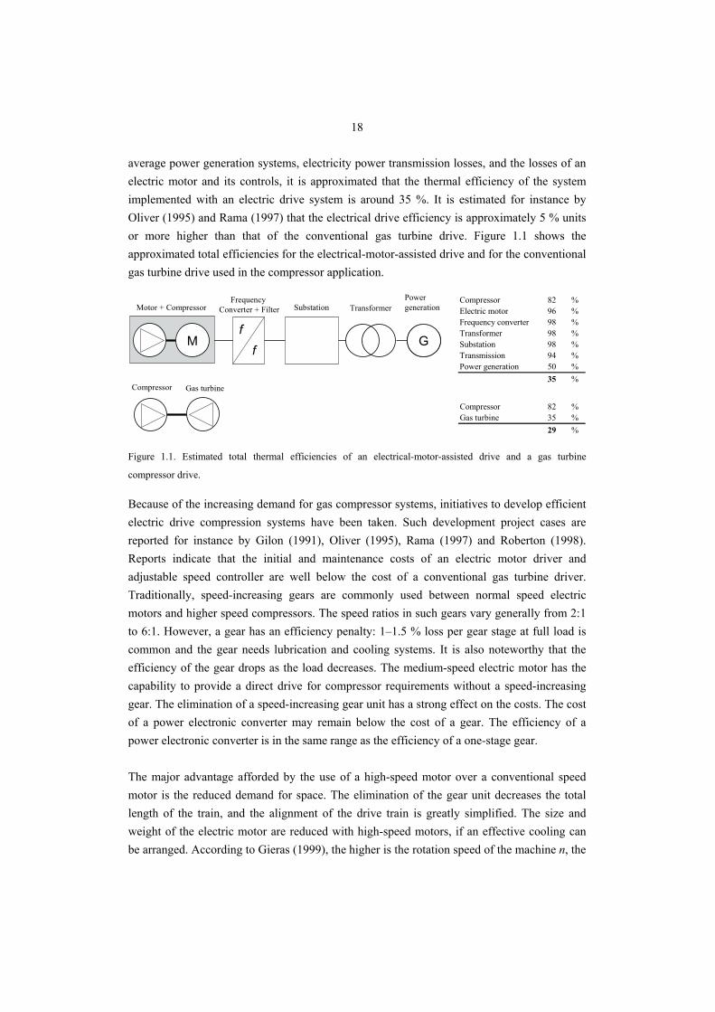
average power generation systems, electricity power transmission losses, and the losses of an electric motor and its controls, it is approximated that the thermal efficiency of the system implemented with an electric drive system is around 35 %. It is estimated for instance by Oliver (1995) and Rama (1997) that the electrical drive efficiency is approximately 5 % units or more higher than that of the conventional gas turbine drive. Figure 1.1 shows the approximated total efficiencies for the electrical-motor-assisted drive and for the conventional gas turbine drive used in the compressor application.
Mff
GG
Motor + CompressorFrequency
Converter + Filter TransformerPower generationSubstation
Compressor Gas turbine
Compressor 82 %Electric motor 96 %Frequency converter 98 %Transformer 98 %Substation 98 %Transmission 94 %Power generation 50 %
35 %
Compressor 82 %Gas turbine 35 %
29 %
Figure 1.1. Estimated total thermal efficiencies of an electrical-motor-assisted drive and a gas turbine
compressor drive.
Because of the increasing demand for gas compressor systems, initiatives to develop efficient electric drive compression systems have been taken. Such development project cases are reported for instance by Gilon (1991), Oliver (1995), Rama (1997) and Roberton (1998). Reports indicate that the initial and maintenance costs of an electric motor driver and adjustable speed controller are well below the cost of a conventional gas turbine driver. Traditionally, speed-increasing gears are commonly used between normal speed electric motors and higher speed compressors. The speed ratios in such gears vary generally from 2:1 to 6:1. However, a gear has an efficiency penalty: 1–1.5 % loss per gear stage at full load is common and the gear needs lubrication and cooling systems. It is also noteworthy that the efficiency of the gear drops as the load decreases. The medium-speed electric motor has the capability to provide a direct drive for compressor requirements without a speed-increasing gear. The elimination of a speed-increasing gear unit has a strong effect on the costs. The cost of a power electronic converter may remain below the cost of a gear. The efficiency of a power electronic converter is in the same range as the efficiency of a one-stage gear. The major advantage afforded by the use of a high-speed motor over a conventional speed motor is the reduced demand for space. The elimination of the gear unit decreases the total length of the train, and the alignment of the drive train is greatly simplified. The size and weight of the electric motor are reduced with high-speed motors, if an effective cooling can be arranged. According to Gieras (1999), the higher is the rotation speed of the machine n, the
19
smaller is the electric motor volume V for the same stator linear current density Alinear and air gap magnetic flux density Bδ
nBAPV
δlinear
out≅ . (1.1)
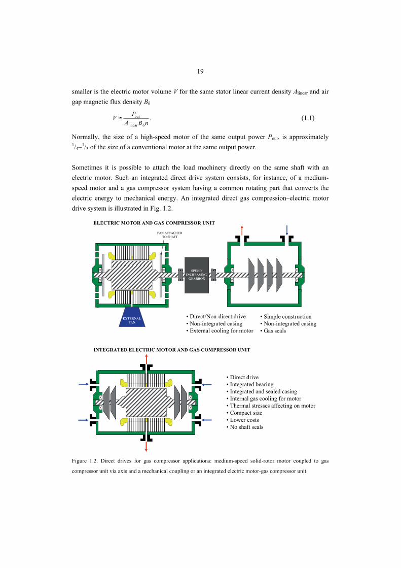
Normally, the size of a high-speed motor of the same output power Pout, is approximately 1/4−1/3 of the size of a conventional motor at the same output power. Sometimes it is possible to attach the load machinery directly on the same shaft with an electric motor. Such an integrated direct drive system consists, for instance, of a medium-speed motor and a gas compressor system having a common rotating part that converts the electric energy to mechanical energy. An integrated direct gas compression–electric motor drive system is illustrated in Fig. 1.2.
• Direct/Non-direct drive• Non-integrated casing• External cooling for motor
INTEGRATED ELECTRIC MOTOR AND GAS COMPRESSOR UNIT
ELECTRIC MOTOR AND GAS COMPRESSOR UNIT
• Simple construction• Non-integrated casing• Gas seals
• Direct drive• Integrated bearing• Integrated and sealed casing• Internal gas cooling for motor• Thermal stresses affecting on motor• Compact size• Lower costs• No shaft seals
EXTERNALFAN
FAN ATTACHEDTO SHAFT
SPEED INCREASING
GEARBOX
Figure 1.2. Direct drives for gas compressor applications: medium-speed solid-rotor motor coupled to gas
compressor unit via axis and a mechanical coupling or an integrated electric motor-gas compressor unit.
20
If the implementation of a compressor and an electric motor on the same shaft can be accomplished, the motor bearings can be used as the integrated machine bearing. Such a construction eliminates the need for the shaft seal and − in such a case − the induction motor can be cooled by the process gas. In addition, if magnetic bearings are used, it is possible to build a hermetically sealed, oil-free compressor system, which can be integrated, for instance, directly on the gas pipeline and be used as a sub-sea pump. Comprehensive studies related to the use of active magnetic bearings in solid rotor applications and at high speeds have been reported for instance by Antila (1998) and Lantto (1999). The solid-rotor induction motor provides a reliable solution for demanding environments where other solutions are prohibited or questionable. However, the problems related to the solid-rotor induction motor diverge from the low electrical performance of the rotor. An integrated approach has an impact on the electric machine design where all the design problems are strongly coupled to each other. In the case of a medium-speed direct drive construction, the rotor may be exposed to high temperatures and mechanical stresses. In some cases, the rotor surfaces should also be able to withstand cooling gases carrying oxidizing acids. Therefore, an integrated approach for the electromagnetic, mechanical and thermal designs is to be carried out coupled for the whole drive system in the preliminary design stage.
1.2 Main Dimensions of a Solid Steel Rotor
Even though the rotor of a high-speed machine is manufactured from a solid piece of steel, the designer cannot ignore the effects of a centrifugal force. The mechanical stresses acting in the rotor should be kept low enough. Actually, centrifugal stresses in high- and medium-speed rotors are no higher than in the largest generators, because the maximum surface velocity is kept within the same limits in both cases. The surface velocity, for the rotor having a 300 mm diameter and a rotating speed of 10 000 rpm, is 157 m/s. Equal surface velocity of the rotor is reached with a rotor having a diameter of 2000 mm and rotational speed of 1500 rpm. This is reached with 50 Hz synchronous generators. Overall, the mechanical constraints give limits to the size of the rotor diameter and the rotor design, affect the choice of materials, set requirements for the quality of manufacture, and manufacturing techniques. The mechanical strengths of the electrical silicon steels limit the surface speeds of laminated rotors to about 150 m/s. Cobalt-iron laminations can be used at somewhat higher speeds, but they are very expensive. The construction of a laminated cage rotor introduces the difficult mechanical problem of keeping the lamination layers tightly together attached to the shaft. Balance fluctuations and vibrations of the rotor caused by the movement of the laminated rotor stack have to be avoided throughout the whole speed range. Therefore, an extremely
21
rigid rotor construction is required in high- and medium-speed applications. In practice, the rotor laminated mass has no rigidity, but it increases the mass of a thin shaft causing low critical frequencies. At a high speed, the stress affecting the rotor iron may reach the level at which mechanical deformations are no longer reversible. Therefore, at higher speeds, the laminated construction may not be used at all without special arrangements. The alternative is to use a solid rotor body equipped with a squirrel cage, Ikeda (1990), Odegard (1996) and Wood (1997). A solid rotor body carrying the squirrel cage is usually made of ferromagnetic material such as carbon steel Fe52 (S355J0/EN 10025), while the squirrel cage is in most of cases made of copper alloy. The manufacturing of such a rotor is, however, complicated. The problem is that the rotor consists of several individual parts. In some cases, the squirrel cage is welded for instance by diffusion welding to the rotor core, but this manufacturing process is expensive. It is also a generally known fact that the apparent resistance of the solid rotor can be decreased by soldering or welding electrically high conductive end-rings to the end faces of the rotor body. In practice, copper or aluminium is often used as an end-ring material in high- and medium-speed machines. Unfortunately, the high centrifugal force caused by the high circumferential velocity, thermal stress and the demand of corrosion tolerance sets constraints for the end-ring material. When the end-ring material is not mechanically able to withstand the forces caused by the high circumferential velocity or the use of other metals should be avoided for some other reason, the rotor can be made of one single piece of ferromagnetic material without any end-rings. Diameter of the Rotor The mechanical tangential stress affecting the rotor is one of the parameters in the determination of the output torque of the motor. The torque T may be calculated from the electro-magnetic rotor surface tangential stress σtan
r2
tan π2 LrT σ= , (1.2)
where Lr and r are the length and the radius of the rotor, respectively. According to Eq. (1.2), an increase in the rotor diameter has a strong effect on the torque. The increase in the rotor diameter gives the benefit of a higher generated torque if the tangential stress is kept constant. However, the maximum rotor diameter is limited by the tangential stress affecting the rotor and the mechanical strength of the rotor material. While the rotor diameter increases, the circumferential force increases and. A solid rotor construction has to withstand higher mechanical stresses. According to Ylinen (1970), the mechanical stress affecting a cylindrical solid rotor can be estimated as
22
22max ΩrCρσ = , (1.3)
where ρ is the mass density of the material and Ω is the angular velocity of the rotor. The maximum stress of a smooth homogenous cylinder takes places at the centre of the cylinder. If the cylinder is hollow, the maximum stress will be found at the inner radius of the cylinder. The factor C for a cylinder can be estimated
83 vC +
= , (smooth homogenous cylinder) (1.4)
43 vC +
= , (cylinder with a small bore) (1.5)
1≈C , (thin cylinder) (1.6)
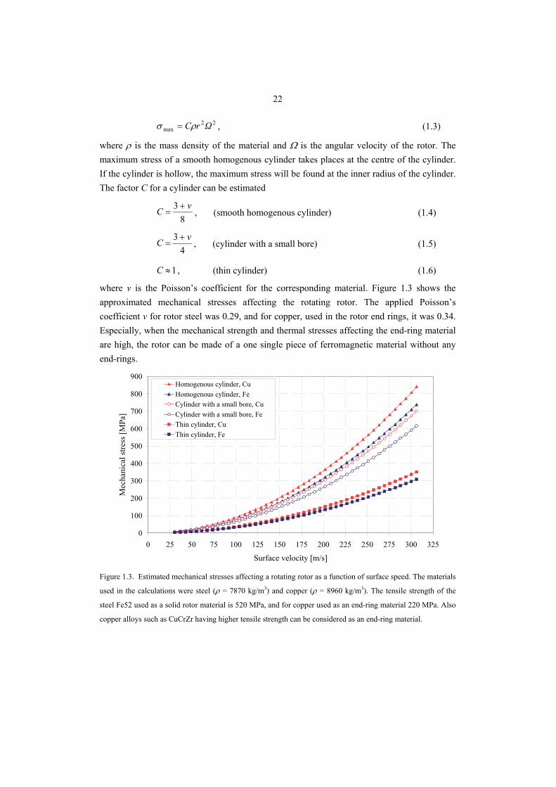
where v is the Poisson’s coefficient for the corresponding material. Figure 1.3 shows the approximated mechanical stresses affecting the rotating rotor. The applied Poisson’s coefficient v for rotor steel was 0.29, and for copper, used in the rotor end rings, it was 0.34. Especially, when the mechanical strength and thermal stresses affecting the end-ring material are high, the rotor can be made of a one single piece of ferromagnetic material without any end-rings.
0
100
200
300
400
500
600
700
800
900
0 25 50 75 100 125 150 175 200 225 250 275 300 325
Surface velocity [m/s]
Mec
hani
cal s
tress
[MPa
]
Homogenous cylinder, CuHomogenous cylinder, FeCylinder with a small bore, CuCylinder with a small bore, FeThin cylinder, CuThin cylinder, Fe
Figure 1.3. Estimated mechanical stresses affecting a rotating rotor as a function of surface speed. The materials
used in the calculations were steel (ρ = 7870 kg/m3) and copper (ρ = 8960 kg/m3). The tensile strength of the
steel Fe52 used as a solid rotor material is 520 MPa, and for copper used as an end-ring material 220 MPa. Also
copper alloys such as CuCrZr having higher tensile strength can be considered as an end-ring material.
23
The performance improvement in a solid rotor can be achieved by slitting the cross-section of the rotor in such a way that a better flux penetration into the rotor will be reached. The slitting also intensifies the cooling of the rotor, because the cooling surface of the rotor increases. The drawback of the axial slitting is that the ruggedness of the solid rotor is partly lost. The highest mechanical stress occurs either on the centre line of the cylinder or at the roots of the rotor teeth. This has to be taken into account when determining the mechanical performance and in the fatigue life prediction for a notched component. The analysis of the mechanical stresses affecting the roots of the solid rotor teeth is discussed in detail in Chapter 3. Length of the Rotor The length of the rotor is limited by the specific frequencies. At the critical speed, the rotor is operating at a range where the unbalance coincides with the natural frequency of the rotor and the rotor may start to vibrate excessively. If a rotor is operated at or near the critical speed, it will exhibit high vibration levels, and is likely to be damaged. The amplitude of the vibration is only limited by the damping capacity of the system, which is low in the robust solid rotor construction. Because the solid rotor is made of one single piece of ferromagnetic material, its critical frequencies are inherently high. The rigidity of the rotor depends highly on the elasticity and the density of the material as well as on the geometry. Young’s modulus E describes the elasticity of the core material. Therefore, it is one of the most important material characteristics when the applicability for high-speed operation is considered. According to Wiart (1982), the estimate for the maximum length of the rotor from the critical point of view can be found
AEI
kΩnL
ρ
222 π
= , (1.7)
where A is the cross-section of the cylinder and n is the ordinal of the critical speed and I is the modulus of inertia. The variable k is defined as a ratio between the nth critical frequency and the nominal angular velocity
n
C
ΩΩk = . (1.8)
Taking into account the safety factor ksafe for the maximum mechanical stress, the ratio between the rotor length Lr and the radius r can be estimated
4safer
4π
σCE
kkn
rL
= . (1.9)
Considering the critical speed, it would be better to have a short and thick rotor construction to achieve high speeds without vibrations. To be absolutely sure about this the first critical
24
speed should be above the operation range of the rotor. Nevertheless, the high-speed machine is often operated above its lowest critical speed between the first and the second specific frequencies. However, in high-speed drive systems, the rotating rotor may pass through one, two, or more lateral critical speeds during the start-up.
1.3 Losses and Cooling of Solid-Rotor Induction Motor
Electric motor efficiency describes the ability of an electric motor to convert electrical energy to mechanical energy. The motor efficiency η can be expressed as a ratio between the mechanical output power Pout and the supplied electrical input power Pin
%100in
out ⋅=PP
η . (1.10)
The power absorbed in the electric motor is the loss incurred in making the electro-mechanical energy conversion. The total loss power Ploss of the motor can be expressed as a difference between supplied power Pin and mechanical output energy Pout
outinloss PPP −= . (1.11)
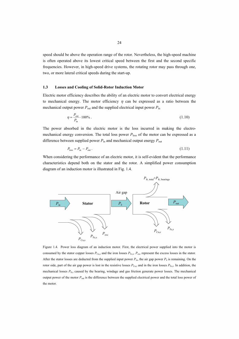
When considering the performance of an electric motor, it is self-evident that the performance characteristics depend both on the stator and the rotor. A simplified power consumption diagram of an induction motor is illustrated in Fig. 1.4.
Air gap
RotorStator
PCu,sPFe,s
PexcPCu,r
PFe,r
Pfr, total+Pfr, bearings
PoutPin Pδ
Figure 1.4. Power loss diagram of an induction motor. First, the electrical power supplied into the motor is
consumed by the stator copper losses PCu,s and the iron losses PFe,s. Pexc represent the excess losses in the stator.
After the stator losses are deducted from the supplied input power Pin, the air gap power Pδ is remaining. On the
rotor side, part of the air gap power is lost in the resistive losses PCu,r and in the iron losses PFe,r. In addition, the
mechanical losses Pfr,r caused by the bearing, windage and gas friction generate power losses. The mechanical
output power of the motor Pout is the difference between the supplied electrical power and the total loss power of
the motor.
25
The electrical power needed during the running operation is fed to the motor from an external source. First, part of the supplied electrical power is consumed in the stator windings. The stator loss is a sum of the copper loss PCu,s the iron loss PFe,s and the excess losses Pexc existing on the stator side
excsFe,sCu,losss, PPPP ++= . (1.12)
The air gap power Pδ transfers the power from the stator to the rotor over the air gap. The air gap power can be defined as
remlosss,inδ ΩTPPP =−= . (1.13)
The electromagnetic torque Tem includes the axial output torque and the loading torque caused by the friction of the bearings and the windage of the rotating rotor. In the rotor, part of the air gap power is lost in the rotor resistance, rotor iron losses, and in the rotor friction losses. The rest of the air gap power is converted into mechanical output power Pout. The rotor total electrical losses Pr,loss can be divided into fundamental resistive losses Pfund,r, which are associated with the electromagnetic torque production, into surface losses Psurf,r caused by the eddy-currents induced by the air gap harmonics, and into hysteresis losses Physt,r caused by to the pulsating excitation of the rotor iron. In addition to the electrical rotor losses, mechanical losses caused by the bearing and windage generate additional power losses
rfr,rhyst,rsurf,rfund,lossr, PPPPP +++= . (1.14)
Contrary to the laminated rotor bodies, the ferromagnetic solid rotor materials do not have a laminated structure to limit the induced eddy-currents. Therefore, the eddy-current losses, which are proportional to the square of the frequency, are considerably high. The friction losses, which are proportional to the cube of the speed, can be a dominant part of high-speed motor losses. The resistive losses on the rotor depend on the electrical resistivity of the applied material. The rotor resistive losses are also called rotor Joule losses, and these losses are the dominating ones. They consist of rotor fundamental losses and rotor surface losses. In the whole rotor volume V, the total Joule loss PJ,r can be estimated from the volume integral of the current densities squared
∫ ∫ ∫=V
VP d2rJ, Jρ , (1.15)
where ρ is the resistivity of the material.
26
The electrical losses of the solid steel rotor are closely connected to the slip of the rotor. The per unit slip s is defined as a ratio of the rotor slip frequency to the stator supply frequency fs
s
slip
s
rs
s
rs
ff
ΩΩΩ
s =−
=−
=ω
ωω . (1.16)
In Eq. (1.16), Ωs is the synchronous mechanical angular frequency of the machine corresponding to the supply frequency fs and Ωr is the mechanical angular frequency of the loaded rotor. Corresponding electrical angular frequencies for the stator and the rotor are ωs and ωr. Rotor fundamental losses Pfund,r together with the surface loss Psurf,r represent the dominant part of the total solid rotor losses Pr,loss. The fundamental rotor losses are proportional to the per-unit slip value. Because of the poor electromagnetic properties of the solid rotor, the per-unit slip tends to be large compared with the slip of a squirrel-cage rotor. Thus, to minimize the rotor losses and to achieve a high electrical efficiency, the nominal operation point of the motor should occur at a low value of per-unit slip. The rotor fundamental losses can be calculated from the well-known relationship between the air gap power and the per-unit slip
sPP ⋅= δrfund, . (1.17)
Consequently, the rotor fundamental efficiency may be defined as
sP
sPPPPP
−=−
=−
= 1δ
δδ
δ
rfund,δrfund,η . (1.18)
However, in the machines with a solid rotor, the air gap harmonics generate eddy-currents that have a low penetration depth. If the rotor hysteresis loss is neglected as insignificant, a simple formulation for the determination of the surface losses Psurf,r can be written
rfund,lossr,rsurf, PPP −= . (1.19)
The mechanical output power Pout of the rotor can be determined from the input power and the losses generated
rfr,lossr,δout PPPP −−= . (1.20)
The electromechanical output power Pmech at the rated speed of the motor can also be defined as a product of the electromagnetic torque Tem and the mechanical angular velocity of the rotor Ωr
( ) ( ) ⎟⎟⎠
⎞⎜⎜⎝
⎛−=⎟⎟
⎠
⎞⎜⎜⎝
⎛−==
pfsT
psTΩTP s
ems
emremmechπ211 ω , (1.21)
where s is the per-unit slip, p is the number of pole pairs, ωs is the stator angular frequency and fs is the frequency supplied into the stator winding.
27
At very high speeds the friction between a rotating rotor and a cooling gas increases remarkably. The analyses of friction losses in the air gap of high-speed solid motors are carried out by Larjola (1991), Saari (1998) and Kuosa (2002). The friction loss caused by the rotating surface of the rotor depends highly on the rotor dimensions and the angular velocity of the rotor. Owing to the high angular velocity of the rotor, the estimation of the friction losses is very important. The calculation of friction and cooling loss is often performed using analytical formulae based on experimental research. According to Saari (1998) and Aglen (2003), the friction power Pfr,r associated with the resisting drag torque of a rotation cylinder with the radius r can be estimated in a simple case by using the equation
r43
rTfrfr, π LrΩρCkP = , (1.22a)
where Ωr is the angular velocity of the rotor, r is the rotor radius and Lr is the axial length of the slitted rotor part. The torque coefficient CT depends on the tip Reynolds number. The coefficient should be determined separately for different flow regimes. Torque coefficients for the active rotor core part have been proposed for instance by Bilgren (1973). According to Larjola (1991), the surface roughness coefficient kf is 1.0 for a smooth rotor and approximately 2.5 with an axially slitted rotor surface. The friction losses are proportional to the cube of the speed. Furthermore, the rotor forces the axial cooling gas flow into a tangential movement. This causes an additional power loss Pf,a which can be approximated with
2m2af, uqkP = , (1.22b)
where k2 is the velocity factor, qm is the mass flow rate of the cooling gas and u is the peripheral speed of the rotor. The ends of the rotor do also have friction losses. The power needed to rotate the rotor end is
( )51
52
3Tendfr, 2
1 rrCP −= ρω , (1.22c)
where r2 and r1 are the outer and inner radii of the end, respectively. CT is the corresponding torque coefficient for the rotor end, which can be found for instance from Kreith (1968). In electrical machines, the free space for the rotor ends in the end-winding area is typically large, and the rotor end acts like a centrifugal pump. The total loss due to the gas friction is a sum of the aforementioned loss components, that is,
endfr,af,rfr,totalfr, 2PPPP ++= . (1.23)
The power loss, caused by the gas friction losses, is taken from the axle power of the motor. Therefore, smooth rotor surfaces are preferred over slitted ones at high speeds.
28
The mechanical utilization factor is a factor describing the power versus the motor size. The larger the utilization factor, the smaller the motor physical dimensions and the more efficient the cooling of the motor must be (Vogt 1996). The mechanical utilization factor Cmech can be defined as
syncheff2δ
mechmech nLD
PC = , (1.24)
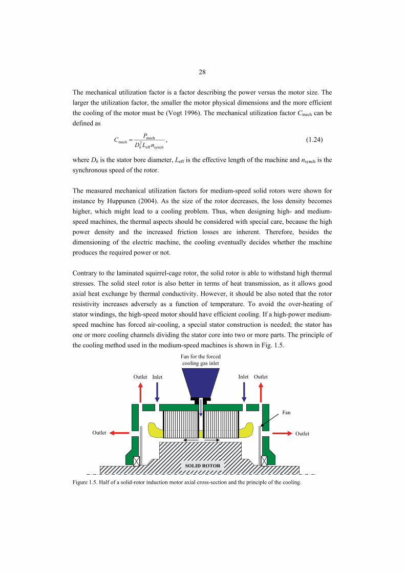
where Dδ is the stator bore diameter, Leff is the effective length of the machine and nsynch is the synchronous speed of the rotor. The measured mechanical utilization factors for medium-speed solid rotors were shown for instance by Huppunen (2004). As the size of the rotor decreases, the loss density becomes higher, which might lead to a cooling problem. Thus, when designing high- and medium-speed machines, the thermal aspects should be considered with special care, because the high power density and the increased friction losses are inherent. Therefore, besides the dimensioning of the electric machine, the cooling eventually decides whether the machine produces the required power or not. Contrary to the laminated squirrel-cage rotor, the solid rotor is able to withstand high thermal stresses. The solid steel rotor is also better in terms of heat transmission, as it allows good axial heat exchange by thermal conductivity. However, it should be also noted that the rotor resistivity increases adversely as a function of temperature. To avoid the over-heating of stator windings, the high-speed motor should have efficient cooling. If a high-power medium-speed machine has forced air-cooling, a special stator construction is needed; the stator has one or more cooling channels dividing the stator core into two or more parts. The principle of the cooling method used in the medium-speed machines is shown in Fig. 1.5.
Fan for the forcedcooling gas inlet
Outlet
OutletOutlet
Fan
SOLID ROTOR
InletInletOutlet
Figure 1.5. Half of a solid-rotor induction motor axial cross-section and the principle of the cooling.
29
The cooling gas is blown into the machine through the radial cooling ducts. Then the cooling gas flows along the air gap directing towards the end winding space. There are outlets at both sides of the frame between the stator core and end bells. Finally, the cooling fans attached to the ends of the motor shaft blow the cooling gas out from the machine frame. Especially in direct drive applications, it is possible to cool the motor by the process gas. In the case of natural gas compression systems, the cooling may use high-pressure methane that is much more efficient than air-cooling at ambient pressure.
1.4 Calculation of a Solid-Rotor Machine Performance
Traditionally, the design and performance analysis of rotating electric machines has been performed by analytical methods, by which the equivalent circuit parameters have been obtained. The veracity of the parameters used in the equivalent circuit is essential, especially in the accurate calculation of the performance of the induction motor. Induction motor drives are often variable-speed systems, in which the drive performance depends, to some extent, on the correctness of the equivalent circuit parameters. The parameters of an induction machine are not constant. Especially, in a solid-rotor induction motor, the rotor impedance is a function of penetration depth, which varies with slip and the magnetic state of the rotor. In a solid rotor, the current is eddy and distributive, which decides that the rotor parameters are also distributive. The analytical calculation routines have usually been designed for the analysis of squirrel cage induction motors. To model accurately the distributed electromagnetic fields inside the solid-rotor induction motor, one of the methods to be used is the numerical finite element method. The majority of electromagnetic machinery and devices nowadays cannot be analyzed purely by analytical means because of their complicated structure and the materials with nonlinear properties. The use of FEM techniques is becoming a common practice among electric machine manufacturers, Szücs (2001). For solid rotor research and design processes, the FEM-based analysis appears to be, up to the present, the leading method to estimate and compare rotor designs. The finite element method is able to calculate the non-linear magnetic fields even in complicated geometries, and it takes into account the effect of the spatial harmonics. It also allows the coupling between the field equations and the voltage equations of the windings and the motion equation of the rotor. The time harmonics in the supply voltage may also in some cases be taken into account, Kanerva (2005). In this thesis, numerical, finite-element-based software is used as a cornerstone in the determination of the solid-rotor induction motor performance. However, a two-dimensional finite element analysis of a three-dimensional magnetic field problem is not a simple task. The effect of the rotor end-region fields have somehow to be taken into account in the 2D
30
model. This can, to a certain extent, be tackled with an end-factor, which modifies the rotor resistivity. In chapter 6 of this thesis, an end-factor, which takes into account the curved current paths in the end regions of the ferromagnetic rotor, is determined by experimental and finite element studies. Also the effect of the solid rotor ends on the rotor phase angle is determined. The veracity of the applied 2D finite element method with respect to the real phenomenon is demonstrated by numerous laboratory measurements.
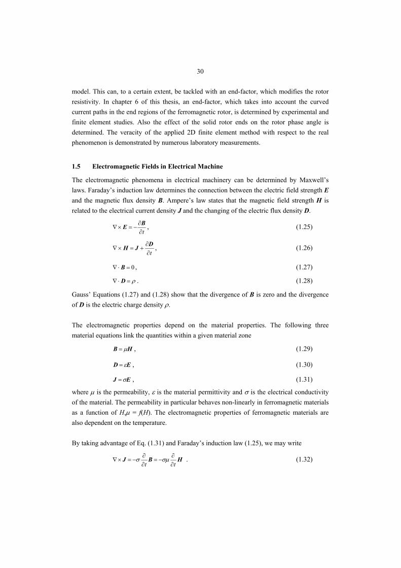
1.5 Electromagnetic Fields in Electrical Machine
The electromagnetic phenomena in electrical machinery can be determined by Maxwell’s laws. Faraday’s induction law determines the connection between the electric field strength E and the magnetic flux density B. Ampere’s law states that the magnetic field strength H is related to the electrical current density J and the changing of the electric flux density D.
t∂∂
−=×∇BE , (1.25)
t∂∂
+=×∇DJH , (1.26)
0=⋅∇ B , (1.27)
ρ=⋅∇ D . (1.28)
Gauss’ Equations (1.27) and (1.28) show that the divergence of B is zero and the divergence of D is the electric charge density ρ. The electromagnetic properties depend on the material properties. The following three material equations link the quantities within a given material zone
HB μ= , (1.29)
ED ε= , (1.30)
EJ σ= , (1.31)
where μ is the permeability, ε is the material permittivity and σ is the electrical conductivity of the material. The permeability in particular behaves non-linearly in ferromagnetic materials as a function of H,μ = f(H). The electromagnetic properties of ferromagnetic materials are also dependent on the temperature. By taking advantage of Eq. (1.31) and Faraday’s induction law (1.25), we may write
HBJtt ∂
∂−=
∂∂
−=×∇ σμσ . (1.32)
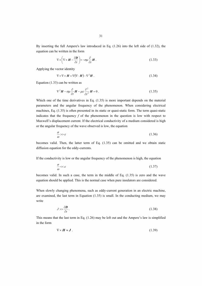
31
By inserting the full Ampere's law introduced in Eq. (1.26) into the left side of (1.32), the equation can be written in the form
HDHtt ∂
∂−=⎟
⎠⎞
⎜⎝⎛
∂∂
−×∇×∇ σμ . (1.33)
Applying the vector identity
( ) HHH 2∇−⋅∇∇=×∇×∇ . (1.34)
Equation (1.33) can be written as
02
22 =
∂∂
−∂∂
−∇ HHHtt
μεσμ . (1.35)
Which one of the time derivatives in Eq. (1.35) is more important depends on the material parameters and the angular frequency of the phenomenon. When considering electrical machines, Eq. (1.35) is often presented in its static or quasi-static form. The term quasi-static indicates that the frequency f of the phenomenon in the question is low with respect to Maxwell’s displacement current. If the electrical conductivity of a medium considered is high or the angular frequency of the wave observed is low, the equation
εωσ
>> (1.36)
becomes valid. Then, the latter term of Eq. (1.35) can be omitted and we obtain static diffusion equation for the eddy-currents. If the conductivity is low or the angular frequency of the phenomenon is high, the equation
εωσ
<< (1.37)
becomes valid. In such a case, the term in the middle of Eq. (1.35) is zero and the wave equation should be applied. This is the normal case when pure insulators are considered. When slowly changing phenomena, such as eddy-current generation in an electric machine, are examined, the last term in Equation (1.35) is small. In the conducting medium, we may write
tJ
∂∂
>>D . (1.38)
This means that the last term in Eq. (1.26) may be left out and the Ampere’s law is simplified in the form
JH ≈×∇ . (1.39)
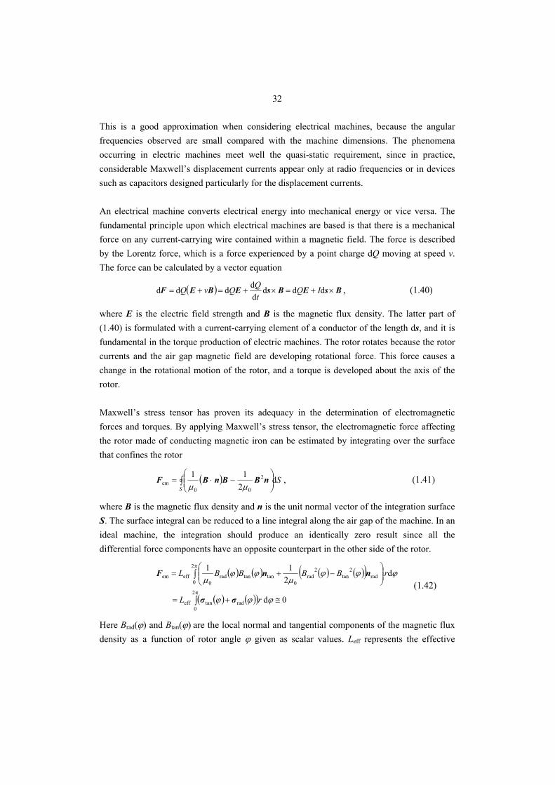
32
This is a good approximation when considering electrical machines, because the angular frequencies observed are small compared with the machine dimensions. The phenomena occurring in electric machines meet well the quasi-static requirement, since in practice, considerable Maxwell’s displacement currents appear only at radio frequencies or in devices such as capacitors designed particularly for the displacement currents. An electrical machine converts electrical energy into mechanical energy or vice versa. The fundamental principle upon which electrical machines are based is that there is a mechanical force on any current-carrying wire contained within a magnetic field. The force is described by the Lorentz force, which is a force experienced by a point charge dQ moving at speed v. The force can be calculated by a vector equation
( ) BsEBsEBEF ×+=×+=+= dddddddd IQ
tQQvQ , (1.40)
where E is the electric field strength and B is the magnetic flux density. The latter part of (1.40) is formulated with a current-carrying element of a conductor of the length ds, and it is fundamental in the torque production of electric machines. The rotor rotates because the rotor currents and the air gap magnetic field are developing rotational force. This force causes a change in the rotational motion of the rotor, and a torque is developed about the axis of the rotor. Maxwell’s stress tensor has proven its adequacy in the determination of electromagnetic forces and torques. By applying Maxwell’s stress tensor, the electromagnetic force affecting the rotor made of conducting magnetic iron can be estimated by integrating over the surface that confines the rotor
( ) SS
d2
11 2
00em ∫ ⎟⎟
⎠
⎞⎜⎜⎝
⎛−⋅= nBBnBF
μμ, (1.41)
where B is the magnetic flux density and n is the unit normal vector of the integration surface S. The surface integral can be reduced to a line integral along the air gap of the machine. In an ideal machine, the integration should produce an identically zero result since all the differential force components have an opposite counterpart in the other side of the rotor.
( ) ( ) ( ) ( )( )
( ) ( )( ) 0d
d 2
11
π2
0radtaneff
π2
0rad
2tan
2rad
0tantanrad
0effem
≅+=
⎟⎟⎠
⎞⎜⎜⎝
⎛−+=
∫
∫
ϕϕϕ
ϕϕϕμ
ϕϕμ
rL
rBBBBL
σσ
nnF (1.42)
Here Brad(ϕ) and Btan(ϕ) are the local normal and tangential components of the magnetic flux density as a function of rotor angle ϕ given as scalar values. Leff represents the effective
33
length of the machine. Integrating the radial component in a machine with an offset rotor gives the unbalanced magnetic pull. The tangential component of the tension produces the differential pairs of the forces [dFtan(ϕ), dFtan(ϕ + π)] on opposite sides of the rotor (assuming a two-pole motor). The differential force components are dependent on the local tangential stress σtan(ϕ)
( )ϕtanefftan π2d σF rL= . (1.43)
The tangential tension affecting the rotor can be determined directly from the interaction between the rotor surface local current density Jr(ϕ) and the radial air gap flux component Brad(ϕ). Using scalar values gives
( ) ( ) ( ) ( ) ( )ϕϕϕϕμϕσ rradrrad0tan JBJH == . (1.44)
If it is assumed that the air gap magnetic field varies sinusoidally, the sum of all differential electromagnetic tangential forces integrated as scalar values around the rotor perimeter may be expressed as
rrrad
efftan cos2
ˆˆπ ϕ
JBrLF =Σ . (1.45)
The dimensioning of the electric machine decides whether the machine produces the required torque or not. The force acts at the distance of the rotor radius r from the shaft. Thus, the average electromagnetic torque attempting to accelerate the rotor Tem will be
rrrad
rrrrad2
efftanem cos2
ˆˆcos
2
ˆˆπ ϕϕ
JBV
JBrLrFT ≈== Σ , (1.46)
where cosϕr is the power factor and Vr volume of a solid rotor. Accurate definition of the solid rotor power factor is a very challenging task, and therefore this subject is discussed in more detail later in Chapter 5. In the case of the high-speed induction machine, the large shaft power is normally achieved, instead of high electromagnetic torque, via the high angular velocity of the rotor. This is applicable especially in fan, blower and compressor applications, where the loading torque is quadratic and very high values of torque are normally not required. The generated power of the machine can be written as a product of mechanical angular velocity of the rotor Ωr and electromagnetic torque Tem
emr
emremπ2 TpfTΩP == , (1.47)
where p is the number of pole pairs and fr is the rotor frequency.
34
1.6 Finite-Element-Based Solid Rotor Calculation
The determination of the solid-rotor induction motor performance has to be carried out through the solution of Maxwell’s field equations. In order to take into account the whole machine geometry, a large number of partial differential equations or integral equations have to be solved. An effective and widely used method of numerically computing eddy-current fields is the finite element analysis. For accurately solving distributed eddy-current problems containing partial differential equations or integral equations an effective computer program is a useful tool. In this thesis for the determination of the solid-rotor induction motor performance a finite element based numerical analysis was chosen. The comprehensive considerations and covering equations for the finite element method are reported for instance by Arkkio (1987), Silvester (1990) and Biro (1990). The leading process in FEM is subdividing the described machine geometry into portions for which a particular covering equation is valid. The described geometrical portions are further subdivided into a large amount of smaller elements, finite elements. The sizes of finite elements should be well proportioned in the motor geometry and, especially, the meshing of the air gap should be done carefully. The air gap is divided into three layers of equal width: the outer and inner layers are static and the middle layer is the dynamic layer in which the meshing is regenerated for each time step. In saturating parts – such as a solid rotor – the maximum element size is usually considered to be one third of the depth of penetration. Although a fine meshing requires a long computation time, special attention has to be paid also to the meshing of the rotor to accurately describe the complex eddy-current problem in the ferromagnetic solid rotor. Therefore, a very dense meshing of the rotor and, in particular, on its outer layers is preferred. In this thesis, the meshing of the rotor was intentionally selected to be over-dense to accurately calculate the electromagnetic fields in the whole rotor cross section and to be able to compare different rotor designs. In each finite element, a simple polynomial function is used to approximate the solution for the electromagnetic fields. In general, some simplifications have to be made to keep the demand of the computer resources and the calculation time at acceptable levels. When applied to electrical machines, the described problem is usually reduced. With the help of boundary and symmetry conditions, the described problem can usually be reduced to cover only one pole or one pole pair of the machine. This reduces the amount of polynomial functions to be solved and thus the computation time needed is decreased. It is also often rationalized to reduce the electromagnetic field problem to a 2D plane and to use the 2D finite element analysis instead of 3D.
35
The non-linearity of rotor material and the movement of the rotor require the use of the time-stepping method to accurately solve the magnetic field. The assumption of sinusoidal time variation becomes valid only in steady-state operation. The time variation of the induced fields in the non-linear materials of an electric machine is practically never sinusoidal. Thus, a two-dimensional, non-linear, time-stepping finite element analysis was applied in the calculation of the performance characteristics of the solid-rotor induction motor. The calculation is based on the numerical solution of the magnetic vector potential A in the two-dimensionally modelled core region of the machine. To satisfy the non-divergence of the magnetic field, the curl of magnetic vector potential is defined as
BA =×∇ , (1.48)
0=⋅∇ A . (1.49)
Substituting the magnetic vector potential definition in the induction law gives
t∂∂
×−∇=×∇AE . (1.50)
The electric field strength can be written as
φ∇−∂∂
−=tAE , (1.51)
where φ is the reduced electric scalar potential. Equation (1.52) fulfils Equation (1.49) since 0=∇×∇ φ and the induction law is now automatically satisfied.
The current density J can be written as
φσσσ ∇−∂∂
−==tAEJ . (1.52)
The electromagnetic field of the motor in the Cartesian plane can be described in terms of the magnetic vector potential and Ampere’s law as
( ) JA =×∇×∇ υ , (1.53)
where υ is the magnetic reluctivity and J is the current density. The reluctivity is also field dependent and Eq. (1.54) becomes nonlinear. Substituting Eq. (1.53) to (1.54) gives
( ) 0=∇+∂∂
+×∇×∇ φσσυtAA . (1.54)
Equation (1.52) is valid in the eddy-current regions while Eq. (1.53) is valid in the regions of source currents, such as coil currents, and in the regions with no current densities at all J = 0.
36
The current density can be expressed as a function of vector potential A and electric scalar potential ϕ
ϕσσ ∇−∂∂
−=tAJ , (1.55)
where σ is the electric conductivity of the material and t is time. The reluctivities of the stator and rotor irons are defined as single-valued functions of the magnetic field strength. The saturation effects in the stator and the rotor are simultaneously considered, but the eddy-currents in the stator windings and in the laminated stator core are usually ignored. The conductance of the lamination sections and the windings areas is set zero. However, the total resistance of the windings is usually given as an absolute value, that is, the resistive voltage drop of the stator windings is taken into account in the analysis. In two-dimensional FEM calculations, the axial coordinate is chosen to be the z-coordinate. In addition, the vector potential and the current density have only the axial component and the magnetic field is in the xy plane. This facilitates the solution of the field equations and thus reduces the requirements of computer resources. The magnetic vector potential and current density vector can be given by
( ) z,, eA tyxA= , (1.56)
( ) z,, eJ tyxJ= , (1.57)
where x and y are the Cartesian spatial components and ez is the unit vector of the z-direction. If the axial length of the core region in the z-direction is l and the voltage between the ends of the conductor on which an external source is imposed is u, the electric scalar potential φ in the conductor can be defined similarly as in the axial z-direction
zlu
−=φ . (1.58)
The main disadvantage of using finite elements in machine analysis is that the FEM usually involves the use of a large amount of computer capacity. To reduce the number of field equations, the solid conductors placed to a stator slot are simplified and modelled as a single filamentary conductor. This approximation is applicable when the skin effect and proximity effect in the conductor are not a matter of substance. A filamentary conductor is a theoretical circuit element in which the current i is supposed to be uniformly distributed over the conductor radial cross-section. Thus, the conductivity σ is assumed constant in the conductor. The conducting region is thought to form a straight conductor the axial length of which is the same as that of the core region. The two-dimensional eddy-current density in the conducting medium is
37
lu
tσσ −
∂∂
−=AJ . (1.59)
The two-dimensional non-linear eddy-current calculation and the machine terminal voltage must be coupled. In the cases studied, the solid-rotor motors were set up under sine excitation. In addition to voltage supply, to include the end winding effects of the stator coils, Eq. (1.59) is coupled with the following circuit equation
tψ
tiLRiu
dd
dd
ew ++= , (1.60)
where u and i are the voltage and the current of the stator winding, R is the resistance of the winding, ψ is the flux linkage associated with the two-dimensionally modelled magnetic field and Lew is the end-winding inductance, representing the part of flux linkage, which is not included in ψ. In 2D calculations of a solid-rotor induction motor, where the whole rotor is treated as an infinitely long eddy-current area it must be emphasized that the inductance of the rotor end is not taken into account in the coupled circuit equation. Because of this, the rotor power factor angle remains too small and thus, the motor power-factor obtained from the 2D FE analysis is slightly overestimated. The calculation of the electromagnetic force and torque affecting the ferromagnetic rotor core is based on the principle of virtual work. The method of virtual work method allows computing the torque exerted on parts that keep their shape and that are surrounded by air. According to reports by Arkkio (1995) and Coulomb (1983), the virtual work method has proven to give reliable results when computing the air gap torques of rotating electric machines. In the virtual work method, the force is calculated as a partial differential of the magnetic co-energy Wco with respect to the virtual displacement s
∫ ∫∂∂
=∂
∂=
VVWF
HHB
ss 0
co dd , (1.61)
where B is the magnetic flux density, H is the magnetic field intensity and V is the volume studied. It must be noticed that in the two-dimensional case, the volume integral in Eq. (1.62) becomes a surface integration over the air gap finite elements. The electromagnetic torque Tem, exerted in a given direction can be obtained by replacing the virtual displacement s with a virtual angular displacement θ
∫ ∫∂∂
=∂
∂=
VVWT
HHB
0
coem dd
θθ. (1.62)
The comparison of experimental tests and results obtained from the numerical calculations, presented by Saari (1998), Lähteenmäki (2002) and Huppunen (2004), have shown that the time-stepping, finite element analysis is a valuable tool in the design of medium- and high-
38
speed machines. Although the finite element method has been a significant tool in modelling and analysis in this thesis, the emphasis has not been placed on the finite element analysis itself. Finite element calculations are used in the comparative analysis of different solid rotor designs. All the FEM results presented in the following chapters of this thesis are obtained using commercial Flux2D™ software package from CEDRAT.
1.7 Scope of the Work and Outline of the Thesis
The electromagnetic problems related to the solid-rotor induction motor are mostly associated with the low performance of the rotor. Therefore, this thesis provides the methods to improve the electromagnetic performance of large medium-speed induction motors equipped with a solid steel rotor. The rotor designs studied in this thesis are based on the fact that the rotor construction should be extremely robust to withstand the high mechanical stresses caused by the rotational velocity of the rotor. In addition, the rotor material should be able to withstand cooling gases carrying oxidizing acids. Thus, the solid rotors equipped with end-rings, a squirrel cage or coating materials made of copper or aluminium are excluded from the study; these kinds of constructions are mechanically vulnerable since they contain individual parts, which may move with respect to each other and easily lose the rotor balance at high-speed operation. The solid rotors analyzed in this thesis are made of a single piece of ferromagnetic material without any additional parts, because such a rigid rotor construction is able to keep its balance over a large speed range. The thesis aims in design rules for multi-megawatt machines. However, in this thesis, a 120 kW solid-rotor induction motor is used as a small-scale model for such megawatt- range solid-rotor machines. The performance of the 120 kW solid-rotor induction motors is determined by experimental measurements and finite element calculations. The main emphasis is put on the solid steel rotor designs. In this thesis, the target is to improve the performance of a solid-rotor induction motor by traditional methods: by axial slitting of the rotor, with a correct rotor core material and by coating the rotor with a high-resistive stainless ferromagnetic material. The rotor designs covered in this thesis are the simple smooth solid rotor, the axially slitted solid rotor and the solid rotor having a ferromagnetic coating layer. All these comprehensive rotor designs are illustrated in Fig. 1.6. The motor and particularly its stator used in the research work for this thesis resemble an existing product by The Switch Electrical Machines. The rotor of the original product is normally a solid rotor having copper end-rings attached on the end faces. For this particular research, the rotor was replaced with a pure solid steel rotor without copper end-rings. This almost halves the output power of the motor at rated speeds. Although the motor equipped with a solid steel rotor considered in this thesis had an output power of only 120 kW, the main
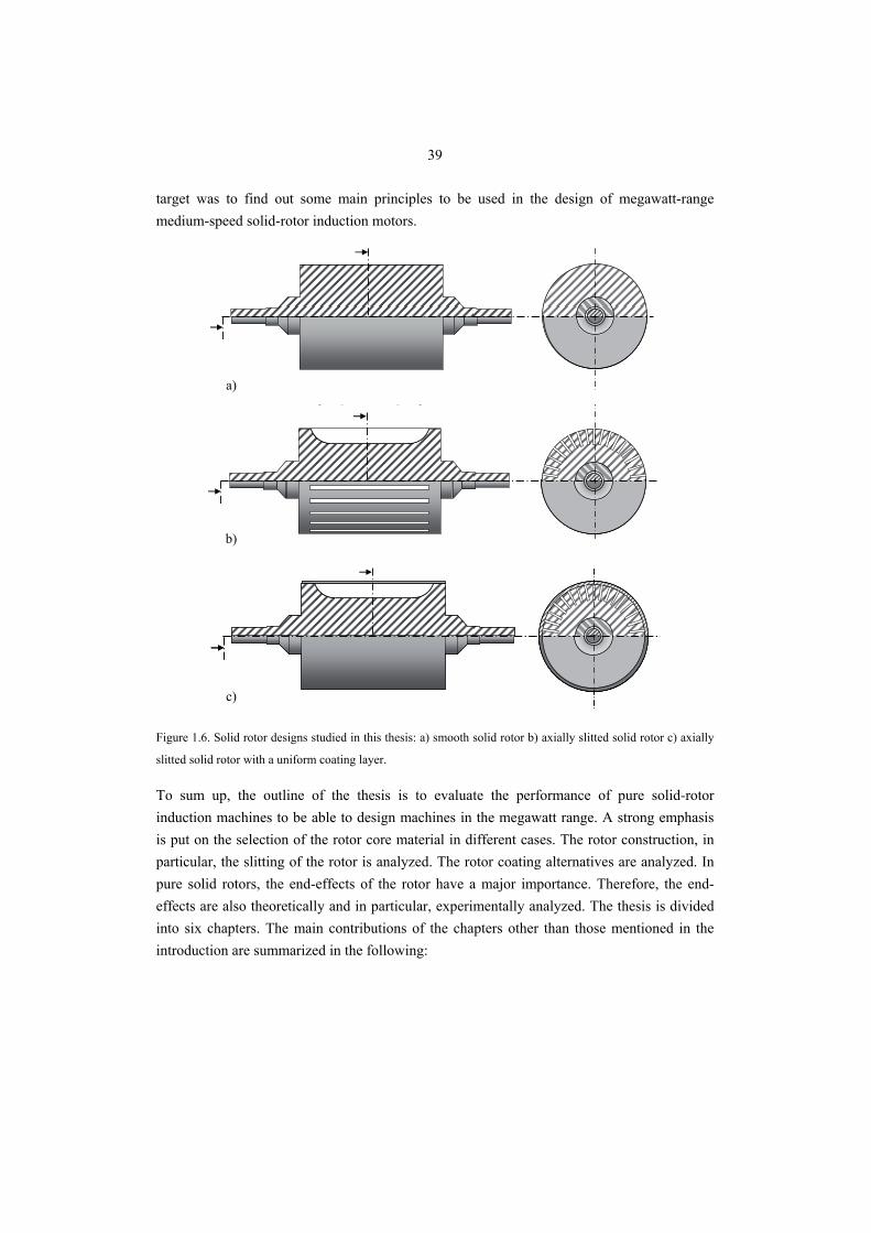
39
target was to find out some main principles to be used in the design of megawatt-range medium-speed solid-rotor induction motors.
a)
b)
c)
Figure 1.6. Solid rotor designs studied in this thesis: a) smooth solid rotor b) axially slitted solid rotor c) axially
slitted solid rotor with a uniform coating layer.
To sum up, the outline of the thesis is to evaluate the performance of pure solid-rotor induction machines to be able to design machines in the megawatt range. A strong emphasis is put on the selection of the rotor core material in different cases. The rotor construction, in particular, the slitting of the rotor is analyzed. The rotor coating alternatives are analyzed. In pure solid rotors, the end-effects of the rotor have a major importance. Therefore, the end-effects are also theoretically and in particular, experimentally analyzed. The thesis is divided into six chapters. The main contributions of the chapters other than those mentioned in the introduction are summarized in the following:
40
Chapter 2 The effect of rotor material on the motor performance is numerically studied on smooth and slitted rotors. The effect of electromagnetic parameters, that is, the saturation flux density, magnetic permeability and electrical resistivity, are studied in detail. In addition, some commercially available materials satisfying the mechanical requirements are included in the study.
Chapter 3 The rotor slitting design is studied. The depth of the rotor slitting and the
number of the rotor slits are analyzed in detail. In addition, the mechanical constraints set by the axial rotor slitting are discussed. The performance of a solid rotor having an odd number of slits and its unbalanced magnetic pull are analyzed.
Chapter 4 To achieve further improvements in the electromagnetic, mechanical and fluid
dynamical properties of a slitted solid-rotor induction motor, the coated rotor construction was analyzed. It is shown by numerical calculations that the rotor surface losses can be reduced by coating the solid rotor surface with a high-resistive material. The effect of the ferromagnetic coating material on the motor performance and desirable electromagnetic coating material properties are discussed.
Chapter 5 The accuracy of the finite element calculations compared with the measured
values is discussed. In addition, the rotor end-effects in solid rotor calculation and the accuracy of the finite element calculations are studied.
Chapter 6 The final chapter presents the conclusions and suggestions for future research
work.
1.8 Scientific Contributions
The scientific contribution of this thesis is: • A slip-dependent end-effect factor for the slitted solid rotor is introduced. It describes
the effect of the curved current paths in the rotor end regions at a wide operation range.
• Solid rotor constructions with odd slit numbers are discussed in detail. • The effects of electromagnetic material parameters on the motor performance are
studied in detail in the cases of smooth and slitted solid rotors. • The effects of high-resistive ferromagnetic coating materials on the motor
performance are analyzed in detail. The optimal design principles for the ferromagnetic coating are discussed.
41
1.9 Most Relevant Scientific Papers Published During the Work
The range of the output power for the reported motors is from 120 kW to 9 MW. All the machines analyzed are medium-speed (~10 000 rpm) solid-rotor induction motors. At the preliminary stage of each megawatt size motor designs, a small-scale prototype motor was used in the calculations and also in the experimental measurements. The results of the work were reported in several scientific papers. The most relevant of the publications listed below are categorized to follow the outline of thesis. The effect of different solid rotor materials in the medium-speed motors was analyzed in two publications. In the first publication P1, the analyzed motor was a 250 kW induction motor equipped with a solid rotor having copper end-rings on the end-faces of the rotor. In the second paper P2, the motor was similar as in P1, except that the rotor was not equipped with copper end-rings. It was concluded in both papers that the most desirable ferromagnetic solid rotor material has a low resistivity and a high saturation flux density. The effect of initial relative permeability was found to be almost negligible. P1 T. Aho, J. Nerg and J. Pyrhönen: ’The Effect of the Rotor Material on the Performance of
Medium-Speed Solid-Rotor Induction Motors’, Proceedings of XII International Symposium on Electromagnetic Fields in Mechatronics, Electrical and Electronic Engineering ISEF 2005, Baiona, Spain 2005.
P2 T. Aho, V. Sihvo, J. Nerg, J. Pyrhönen: ’Rotor Materials for Medium-Speed Solid- Rotor
Induction Motors’, International Electric Machines and Drives Conference (IEMDC) 2007, Antalya, Turkey 2007.
The comparison of different solid rotor slitting strategies was reported in three publications. The first paper P3 deals with different rotor slitting depths in a 200 kW, 10200 rpm solid-rotor induction motor. It was shown that the depth of the rotor slitting should be approximately half of the rotor radius. In the latter two papers P4 and P5, the electrical performance of the motor and the unbalanced pull due to the asymmetric rotor was studied in the case of a 9 MW, 12 000 rpm medium-speed solid-rotor induction motor. It was found out that there are relatively large radial force differences between different rotor slit numbers. It was also found that the odd rotor slit number could be advantageous when the torque ripple and rotor power loss is considered. P3 T. Aho, J. Nerg, J. Sopanen, J. Huppunen, J. Pyrhönen: ’Analyzing the Effect of the Rotor Slit
Depth on the Electric and Mechanical Performance of a Solid-Rotor Induction Motor’, International Review of Electrical Engineering (I.R.E.E), Vol. 1, No. 4, September – October 2006, pp. 516-524.
P4 T. Aho, J. Nerg and J. Pyrhönen: ’The Effect of the Number of Rotor Slits on the Performance
Characteristics of Medium-Speed Solid-Rotor Induction Motor’, Proceedings of 3rd International Conference on Power Electronics, Machines and Drives PEMD 2006, Dublin, Ireland 2006, pp. 515-519.
42
P5 J. Nerg, T. Aho, J. Pyrhönen: ’Effects of an Odd Number of Rotor Slits on the Torque Ripple,
Rotor Losses and Unbalanced Magnetic Pull of a High-Speed, High-Power, Solid-Rotor Induction Motor’, WSEAS Transactions on Power Systems, Vol. 1, Issue 10, October 2006, pp. 1762-1769.
The possibility of coating the solid rotor with a uniform layer made of high-resistivity stainless steel was analyzed in three publications. The analyzed motor was a 9 MW, 12 000 rpm induction motor equipped with a coated solid steel rotor. It was shown in P6 that the coating material resistivity should be approximately three times higher than the resistivity of the rotor core material. It was shown in P7 that the thickness and the resistivity of the coating should be selected in such a way that the air gap harmonics caused by the stator slotting are attenuated in the coating layer. The results of the two previous publications were summarized in P8. P6 T. Aho, J. Nerg and J. Pyrhönen: ’Analysing the effect of the rotor coating on the rotor losses
of medium-speed solid-rotor induction motor’, Proceedings of International Symposium on Power Electronics, Electrical Drives, Automation and Motion, SPEEDAM 2006, Taormina, Italy 2006, pp. 103-107.
P7 T. Aho, J. Nerg, J. Pyrhönen: ’Analyzing the Effect of the Rotor Coating Thickness on the
Rotor Losses of Medium-Speed Solid-Rotor Induction Motor’, Proceedings of 2006 International Conference on Electrical Machines and Systems (ICEMS 2006), Nagasaki, Japan 2006, paper DS2F4-01.
P8 T. Aho, J. Nerg, J. Pyrhönen: ’Decreasing the Rotor Eddy-Current Losses of a Medium-Speed
Solid-Rotor Induction Motor’, 10th Joint MMM/Intermag Conference, 2007, Baltimore, USA. The three-dimensional field problem in the solid rotor end region was analyzed in two publications. A 120 kW small-scale model was used in the studies. In the first publication P9, the length of the rotor end region was experimentally analyzed. It was found that the rotor end region should be axially as short as possible. In the second publication P10, different corrective end-effect factors were analyzed. A slip-dependent end-factor, which takes into account the curved current paths in the rotor ends and also the effect of different motor loading conditions, was proposed. P9 T. Aho, J. Nerg, J. Pyrhönen: ’Optimizing the Axial Length of the Slitted Solid Iron Rotor’,
2007, 2nd IEEE Conference on Industrial Electronics and Applications (ICIEA), 2007, Harbin, China, CD.
P10 T. Aho, J. Nerg, J. Pyrhönen: ’Experimental and Finite Element Analysis of Solid Rotor End
Effects’, 2007, IEEE International Symposium on Industrial Electronics 2007, Vigo, Spain, CD.
43
2. FERROMAGNETIC SOLID ROTOR MATERIALS
The analysis of the performance of a magnetically non-linear solid rotor has been a complicated problem to be tackled with conventional lumped-parameter equivalent circuits. This is because in a solid rotor the path for the magnetic flux and the induced eddy-currents is the same, that is, the ferromagnetic solid rotor core. The magnetic field strength at the surface of the rotor is usually sufficiently high to drive the rotor well into magnetic saturation, thus greatly affecting the eddy-current distribution of the solid iron rotor. The interaction between the induced eddy-currents of the rotor and the revolving field of the air gap produces the electromagnetic torque. It is obvious that the non-linearity of the rotor material permeability must be taken into account when evaluating the performance of a solid-rotor machine. Hence, the solid rotor performance should be determined directly from the analysis of the electromagnetic fields. Most of the early studies on solid rotors, for instance by McConnell and Svedrup (1955), Wood and Concordia (1960), Agarwal (1956), Angst (1962), Jamieson (1968), Chalmers (1972) and Yee and Wilson (1972), were at least partly analytic, and the permeability for the rotor material was kept constant. In the aforementioned reports, the authors showed that the rotor material properties of a solid-rotor motor have a substantial influence on the motor characteristics. However, finite elements were not, in practice, available for the researchers mentioned above and, hence, the exact behaviour of the solid rotor remained partly unresolved. At present, we still have some difficulties in finite element calculations of the solid rotor. However, two-dimensional calculations are well available and describe quite adequately the behaviour of the solid rotor in the radial cross-section of the motor. The main objective of this chapter is to numerically analyze the effects of different ferromagnetic materials on the electromagnetic performance characteristics of a medium-speed solid-rotor induction motor. The intention is also to verify the earlier results or find other desirable properties. Finite element method may bring some new information on the behaviour of the rotor materials. It is also pointed out that all the early studies were made for smooth solid rotor constructions. In this chapter, the effects of different ferromagnetic materials on the electromagnetic performance characteristics of solid-rotor induction motor are comprehensively analyzed by using two-dimensional numerical calculations as the analysis tool. Hence, it has to be borne in mind that the results obtained for the power factor, slip and torque are somewhat too optimistic for a rotor without end rings; nevertheless, a comparison between different materials is well possible.
44
The studied solid rotor constructions present a smooth rotor design without any machined grooves on the rotor surface and an axially slitted rotor. The effects of the initial relative permeability μr0, the saturation flux density Bs and the electrical resistivity ρ of the rotor core material on the motor performance characteristics are studied extensively. To cover a wide range of electromagnetic material property combinations, numerous fictitious ferromagnetic rotor core materials were created. To achieve comparable results, both the stator and the rotor dimensions were kept as constants in all calculations. This limitation had to be adopted to keep the calculation time within the limits of the thesis work. In this study, as a base reference, a 120 kW two-pole, 170 Hz induction motor equipped with a slitted solid iron rotor (rotor diameter 195 mm, stator core length 280 mm) is used. Its synchronous speed is 10200 rpm, rated slip 1 %, efficiency 93 %, cosφ = 0.61 and the rated torque 110 Nm. The rated current of the motor at 230 V (phase voltage) supply is 300 A. The number of coils per pole per phase is 16. These values are used as reference values when comparing rotors made of different materials. The solid rotor of the motor used as a base reference is made of construction steel, the electromagnetic properties of which are Bs = 2.0 T, µr0 = 1000 and ρ = 30 μΩcm. In the FE calculations, the rotor end-effects were taken into account with the Russell’s end factor. The solid rotor end-effects are discussed in more detail in Chapter 5. The electromagnetic properties chosen for the rotor material of the base reference motor are close to the commercial low-carbon steel Fe52. Actually, it has been proven in practice that the Fe52 steel satisfies quite well the practical needs for the rotor material. The actual, commercially available ferromagnetic materials, introduced in the latter part of this chapter, were selected such that they satisfy the mechanical requirements set by the high-speed operation.
2.1 Effect of the Electromagnetic Material Parameters on the Rotor Performance
The magnetization behaviour of a medium can be represented by drawing the magnetic saturation flux density B as a function of magnetic field strength H. A non-linear, single-valued B-H dependence for a ferromagnetic material, taking the magnetic saturation into account, can be expressed with a model comprising of a straight line and an arc tangent curve. The slope of the straight line is defined according to the given initial permeability and the applied magnetic field strength. The non-linear part of the BH curve is defined according to the given magnetic flux density saturation value and the initial permeability. The corresponding mathematical formula applied in the Flux2d™ software can be written
( ) ( )⎟⎟⎠
⎞⎜⎜⎝
⎛ −+=
s
0rs0 2
1πarctanπ
2B
HBHHBμμ
μ , (2.1)
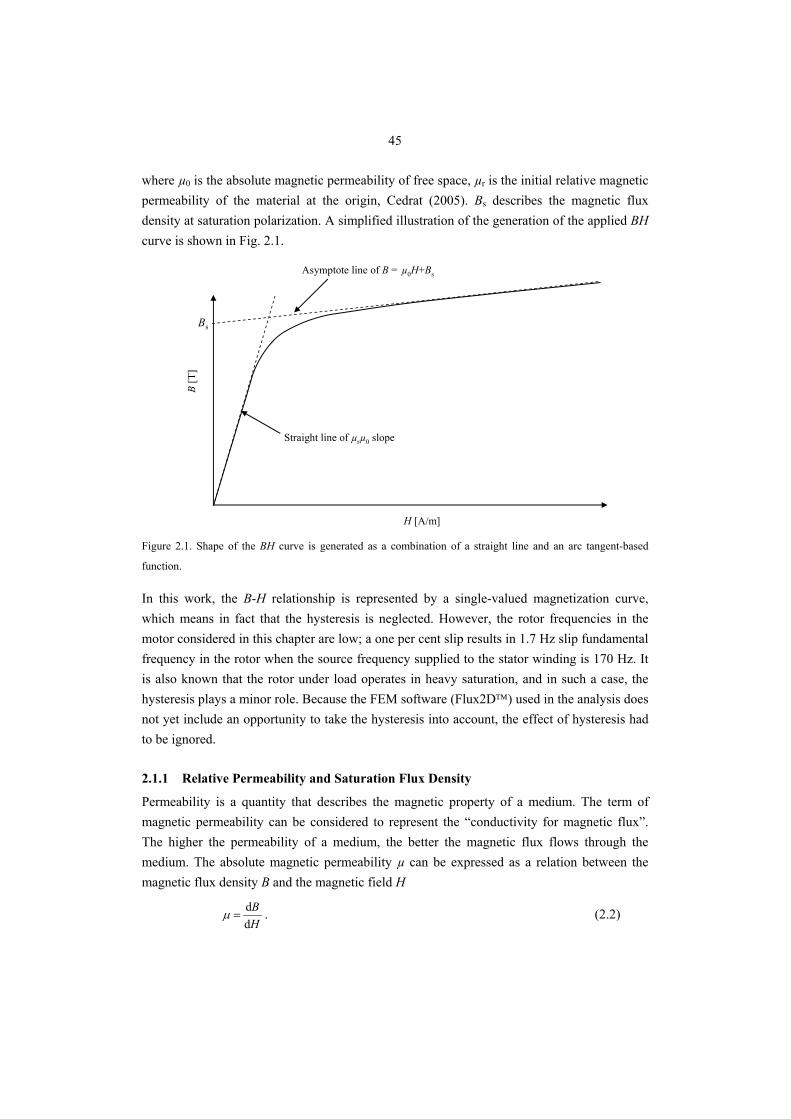
45
where µ0 is the absolute magnetic permeability of free space, µr is the initial relative magnetic permeability of the material at the origin, Cedrat (2005). Bs describes the magnetic flux density at saturation polarization. A simplified illustration of the generation of the applied BH curve is shown in Fig. 2.1.
Bs
B[T
]
H [A/m]
Straight line of µrµ0 slope
Asymptote line of B = µ0H+Bs
Figure 2.1. Shape of the BH curve is generated as a combination of a straight line and an arc tangent-based
function.
In this work, the B-H relationship is represented by a single-valued magnetization curve, which means in fact that the hysteresis is neglected. However, the rotor frequencies in the motor considered in this chapter are low; a one per cent slip results in 1.7 Hz slip fundamental frequency in the rotor when the source frequency supplied to the stator winding is 170 Hz. It is also known that the rotor under load operates in heavy saturation, and in such a case, the hysteresis plays a minor role. Because the FEM software (Flux2D™) used in the analysis does not yet include an opportunity to take the hysteresis into account, the effect of hysteresis had to be ignored.
2.1.1 Relative Permeability and Saturation Flux Density
Permeability is a quantity that describes the magnetic property of a medium. The term of magnetic permeability can be considered to represent the “conductivity for magnetic flux”. The higher the permeability of a medium, the better the magnetic flux flows through the medium. The absolute magnetic permeability µ can be expressed as a relation between the magnetic flux density B and the magnetic field H
HB
dd
=μ . (2.2)
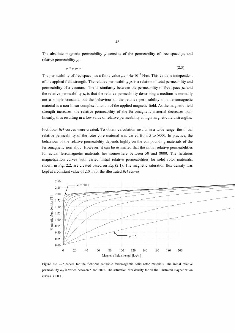
46
The absolute magnetic permeability µ consists of the permeability of free space µ0 and relative permeability µr
r0 μμμ = . (2.3)
The permeability of free space has a finite value μ0 = 4π⋅10−7 H/m. This value is independent of the applied field strength. The relative permeability μr is a relation of total permeability and permeability of a vacuum. The dissimilarity between the permeability of free space μ0 and the relative permeability μr is that the relative permeability describing a medium is normally not a simple constant, but the behaviour of the relative permeability of a ferromagnetic material is a non-linear complex function of the applied magnetic field. As the magnetic field strength increases, the relative permeability of the ferromagnetic material decreases non-linearly, thus resulting in a low value of relative permeability at high magnetic field strengths. Fictitious BH curves were created. To obtain calculation results in a wide range, the initial relative permeability of the rotor core material was varied from 5 to 8000. In practice, the behaviour of the relative permeability depends highly on the compounding materials of the ferromagnetic iron alloy. However, it can be estimated that the initial relative permeabilities for actual ferromagnetic materials lies somewhere between 50 and 8000. The fictitious magnetization curves with varied initial relative permeabilities for solid rotor materials, shown in Fig. 2.2, are created based on Eq. (2.1). The magnetic saturation flux density was kept at a constant value of 2.0 T for the illustrated BH curves.
0.00
0.25
0.50
0.75
1.00
1.25
1.50
1.75
2.00
2.25
2.50
0 20 40 60 80 100 120 140 160 180 200Magnetic field strength [kA/m]
Mag
netic
flux
den
sity
[T]
µr = 5
µr = 8000
Figure 2.2. BH curves for the fictitious saturable ferromagnetic solid rotor materials. The initial relative
permeability µr0 is varied between 5 and 8000. The saturation flux density for all the illustrated magnetization
curves is 2.0 T.
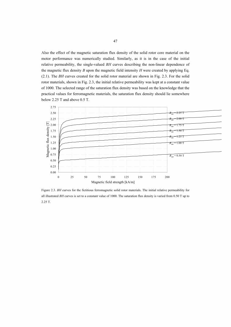
47
Also the effect of the magnetic saturation flux density of the solid rotor core material on the motor performance was numerically studied. Similarly, as it is in the case of the initial relative permeability, the single-valued BH curves describing the non-linear dependence of the magnetic flux density B upon the magnetic field intensity H were created by applying Eq. (2.1). The BH curves created for the solid rotor material are shown in Fig. 2.3. For the solid rotor materials, shown in Fig. 2.3, the initial relative permeability was kept at a constant value of 1000. The selected range of the saturation flux density was based on the knowledge that the practical values for ferromagnetic materials, the saturation flux density should lie somewhere below 2.25 T and above 0.5 T.
0.00
0.25
0.50
0.75
1.00
1.25
1.50
1.75
2.00
2.25
2.50
2.75
0 25 50 75 100 125 150 175 200
Magnetic field strength [kA/m]
Mag
netic
flux
den
sity
[T]
Bsat = 2.25 T
Bsat = 2.00 T
Bsat = 1.75 T
Bsat = 1.50 T
Bsat = 1.25 T
Bsat = 1.00 T
Bsat = 0.50 T
Figure 2.3. BH curves for the fictitious ferromagnetic solid rotor materials. The initial relative permeability for
all illustrated BH curves is set to a constant value of 1000. The saturation flux density is varied from 0.50 T up to
2.25 T.
48
Smooth Solid Rotor Let us first consider the effect of the material’s magnetic properties on the motor performance in the case of a conventional smooth solid rotor. The effects of the initial relative permeability and the magnetic saturation flux density on the electromagnetic torque in the case of a smooth solid rotor are shown in Figs. 2.4 and 2.5. The results obtained from the numerical calculations show that the highest electromagnetic torque is reached when the saturation flux density of the rotor core material is relatively low and the initial relative permeability is high. For this particular rotor, the optimum rotor material from the torque production point of view should have a saturation flux density around only 1.0 T and the initial relative permeability should be above 250. On the other hand, it was found that if the saturation flux density of the applied rotor material is high, it is advantageous from the torque production point of view if the initial relative permeability is lower than that in the previous case. Overall, the initial relative permeability of the applied solid rotor core material can be unexpectedly low. These observations deviate somewhat from the previous studies. For instance, Pyrhönen (1991) proposed that the high magnetic saturation flux density is a desirable electromagnetic property for the ferromagnetic rotor material applied in the smooth solid rotors. In addition, Lähteenmäki (2002) reported that a high permeability flux path in the solid rotor core is required. These conclusions can be said to be partly valid, but in practice, they do not always bring satisfactory results because of the deep saturation of the medium. The results presented here follow quite well the trend shown by Wilson (1969) in his dissertation. In his study, only three values for the initial relative permeability were used: 500, 750 and 1000. Analogously with Wilson’s results, the highest torque was reached with quite a low value of initial relative permeability. However, Wilson (1969) did not discuss the effects of the magnetic saturation flux density of the medium. It is also worth noticing that even though a low permeability gives a high torque, the power factor of the rotor remains very low and low permeability rotor materials may hence be impractical. In this light, the high permeability and saturation flux density suggested by Pyrhönen (1991) and Lähteenmäki (2002) can be understood as a practical choice.
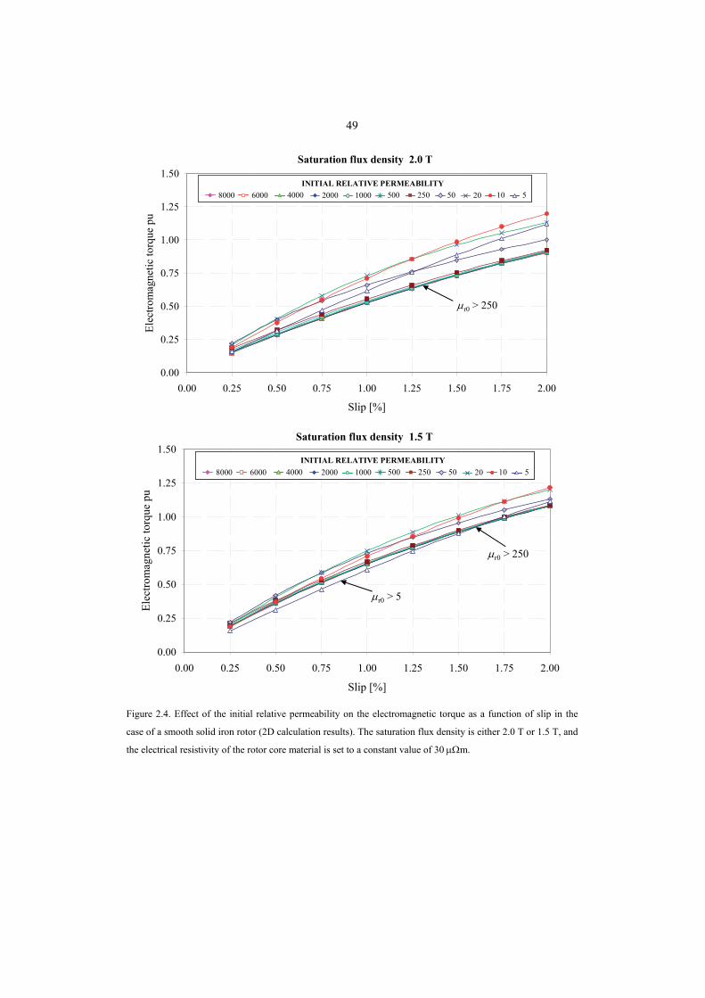
49
0.00
0.25
0.50
0.75
1.00
1.25
1.50
0.00 0.25 0.50 0.75 1.00 1.25 1.50 1.75 2.00
Slip [%]
Elec
trom
agne
tic to
rque
pu
Saturation flux density 2.0 T
8000 6000 4000 2000 500 250 50INITIAL RELATIVE PERMEABILITY
1000 20 10 58000 6000 4000 2000 500 250 50INITIAL RELATIVE PERMEABILITY
1000 20 10 5
μr0 > 250
0.00
0.25
0.50
0.75
1.00
1.25
1.50
0.00 0.25 0.50 0.75 1.00 1.25 1.50 1.75 2.00
Slip [%]
Elec
trom
agne
tic to
rque
pu
Saturation flux density 1.5 T
8000 6000 4000 2000 500 250 50INITIAL RELATIVE PERMEABILITY
1000 20 10 58000 6000 4000 2000 500 250 50INITIAL RELATIVE PERMEABILITY
1000 20 10 5
μr0 > 250
μr0 > 5
Figure 2.4. Effect of the initial relative permeability on the electromagnetic torque as a function of slip in the
case of a smooth solid iron rotor (2D calculation results). The saturation flux density is either 2.0 T or 1.5 T, and
the electrical resistivity of the rotor core material is set to a constant value of 30 μΩm.
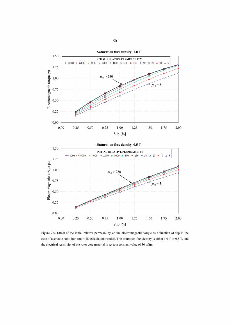
50
0.00
0.25
0.50
0.75
1.00
1.25
1.50
0.00 0.25 0.50 0.75 1.00 1.25 1.50 1.75 2.00
Slip [%]
Elec
trom
agne
tic to
rque
pu
Saturation flux density 1.0 T
8000 6000 4000 2000 500 250 50INITIAL RELATIVE PERMEABILITY
1000 20 10 58000 6000 4000 2000 500 250 50INITIAL RELATIVE PERMEABILITY
1000 20 10 5
μr0 > 250
μr0 = 5
0.00
0.25
0.50
0.75
1.00
1.25
1.50
0.00 0.25 0.50 0.75 1.00 1.25 1.50 1.75 2.00
Slip [%]
Elec
trom
agne
tic to
rque
pu
Saturation flux density 0.5 T
8000 6000 4000 2000 500 250 50INITIAL RELATIVE PERMEABILITY
1000 20 10 58000 6000 4000 2000 500 250 50INITIAL RELATIVE PERMEABILITY
1000 20 10 5
μr0 > 250
μr0 = 5
Figure 2.5. Effect of the initial relative permeability on the electromagnetic torque as a function of slip in the
case of a smooth solid iron rotor (2D calculation results). The saturation flux density is either 1.0 T or 0.5 T, and
the electrical resistivity of the rotor core material is set to a constant value of 30 μΩm.
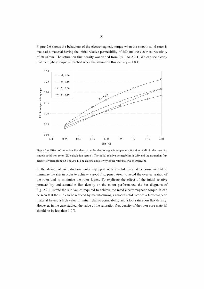
51
Figure 2.6 shows the behaviour of the electromagnetic torque when the smooth solid rotor is made of a material having the initial relative permeability of 250 and the electrical resistivity of 30 μΩcm. The saturation flux density was varied from 0.5 T to 2.0 T. We can see clearly that the highest torque is reached when the saturation flux density is 1.0 T.
0.00
0.25
0.50
0.75
1.00
1.25
1.50
0.00 0.25 0.50 0.75 1.00 1.25 1.50 1.75 2.00
Slip [%]
Elec
trom
agne
tic to
rque
pu
Bsat 1.00
Bsat 1.50
Bsat 2.00
Bsat 0.50
Bs
Bs
Bs
Bs
B s= 1.0 T
Figure 2.6. Effect of saturation flux density on the electromagnetic torque as a function of slip in the case of a
smooth solid iron rotor (2D calculation results). The initial relative permeability is 250 and the saturation flux
density is varied from 0.5 T to 2.0 T. The electrical resistivity of the rotor material is 30 μΩcm.
In the design of an induction motor equipped with a solid rotor, it is consequential to minimize the slip in order to achieve a good flux penetration, to avoid the over-saturation of the rotor and to minimize the rotor losses. To explicate the effect of the initial relative permeability and saturation flux density on the motor performance, the bar diagrams of Fig. 2.7 illustrate the slip values required to achieve the rated electromagnetic torque. It can be seen that the slip can be reduced by manufacturing a smooth solid rotor of a ferromagnetic material having a high value of initial relative permeability and a low saturation flux density. However, in the case studied, the value of the saturation flux density of the rotor core material should no be less than 1.0 T.
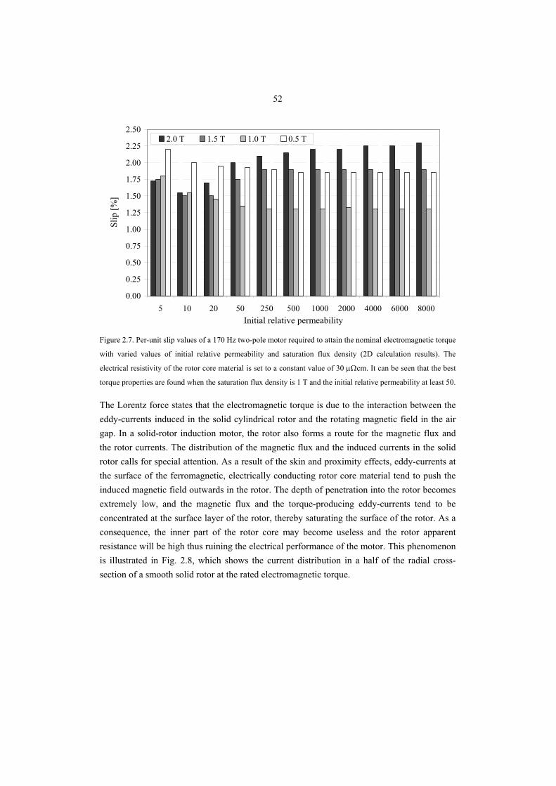
52
0.00
0.25
0.50
0.75
1.00
1.25
1.50
1.75
2.00
2.25
2.50
5 10 20 50 250 500 1000 2000 4000 6000 8000Initial relative permeability
Slip
[%]
2.0 T 1.5 T 1.0 T 0.5 T
Figure 2.7. Per-unit slip values of a 170 Hz two-pole motor required to attain the nominal electromagnetic torque
with varied values of initial relative permeability and saturation flux density (2D calculation results). The
electrical resistivity of the rotor core material is set to a constant value of 30 μΩcm. It can be seen that the best
torque properties are found when the saturation flux density is 1 T and the initial relative permeability at least 50.
The Lorentz force states that the electromagnetic torque is due to the interaction between the eddy-currents induced in the solid cylindrical rotor and the rotating magnetic field in the air gap. In a solid-rotor induction motor, the rotor also forms a route for the magnetic flux and the rotor currents. The distribution of the magnetic flux and the induced currents in the solid rotor calls for special attention. As a result of the skin and proximity effects, eddy-currents at the surface of the ferromagnetic, electrically conducting rotor core material tend to push the induced magnetic field outwards in the rotor. The depth of penetration into the rotor becomes extremely low, and the magnetic flux and the torque-producing eddy-currents tend to be concentrated at the surface layer of the rotor, thereby saturating the surface of the rotor. As a consequence, the inner part of the rotor core may become useless and the rotor apparent resistance will be high thus ruining the electrical performance of the motor. This phenomenon is illustrated in Fig. 2.8, which shows the current distribution in a half of the radial cross-section of a smooth solid rotor at the rated electromagnetic torque.
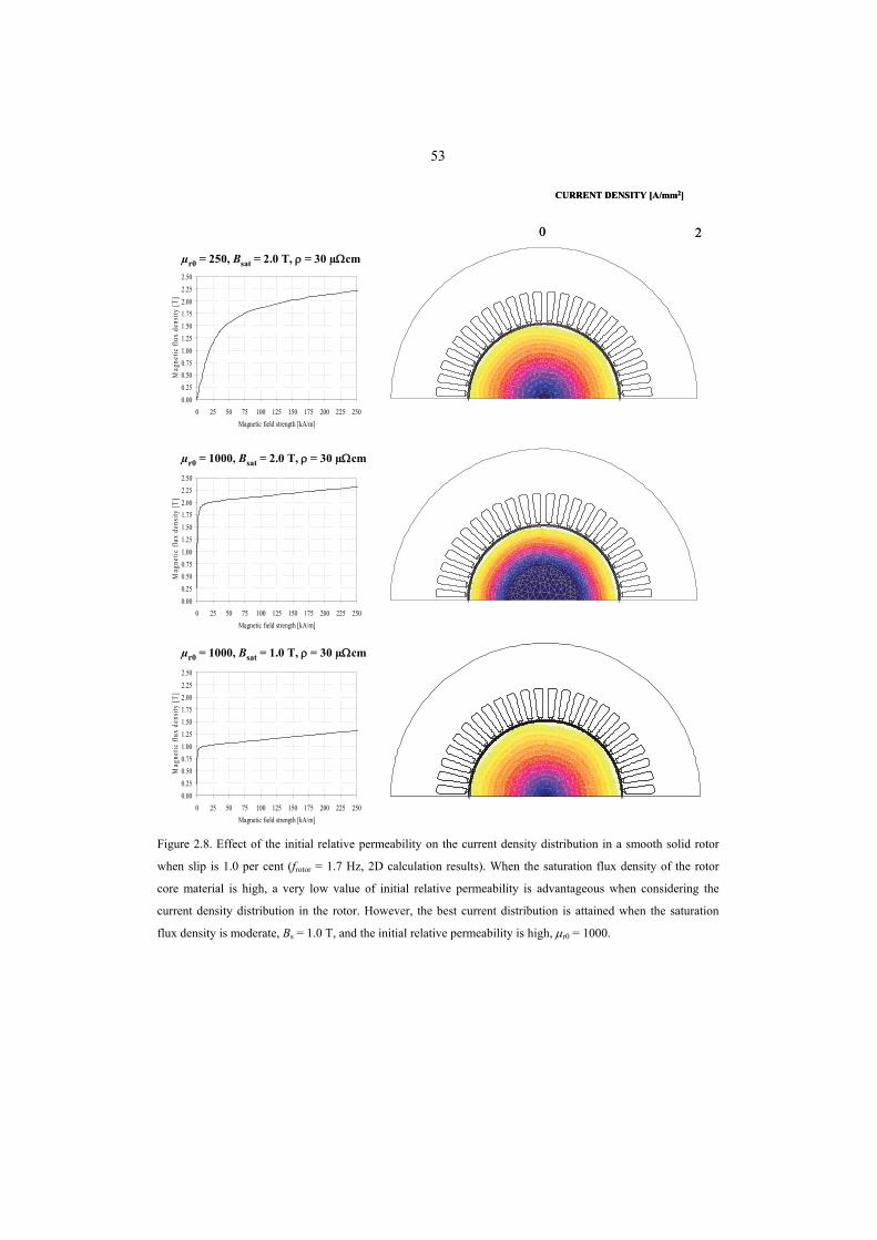
53
µr0 = 250, Bsat = 2.0 T, ρ = 30 µΩcm
µr0 = 1000, Bsat = 2.0 T, ρ = 30 µΩcm
µr0 = 1000, Bsat = 1.0 T, ρ = 30 µΩcm
0.000.250.500.751.001.251.501.752.002.252.50
0 25 50 75 100 125 150 175 200 225 250Magnetic field strength [kA/m]
Mag
netic
flux
den
sity
[T]
0.000.250.500.751.001.251.501.752.002.252.50
0 25 50 75 100 125 150 175 200 225 250Magnetic field strength [kA/m]
Mag
netic
flux
den
sity
[T]
0.000.250.500.751.001.251.501.752.002.252.50
0 25 50 75 100 125 150 175 200 225 250Magnetic field strength [kA/m]
Mag
netic
flux
den
sity
[T]
0 2
CURRENT DENSITY [A/mm2]
0 2
CURRENT DENSITY [A/mm2]
Figure 2.8. Effect of the initial relative permeability on the current density distribution in a smooth solid rotor
when slip is 1.0 per cent (frotor = 1.7 Hz, 2D calculation results). When the saturation flux density of the rotor
core material is high, a very low value of initial relative permeability is advantageous when considering the
current density distribution in the rotor. However, the best current distribution is attained when the saturation
flux density is moderate, Bs = 1.0 T, and the initial relative permeability is high, μr0 = 1000.
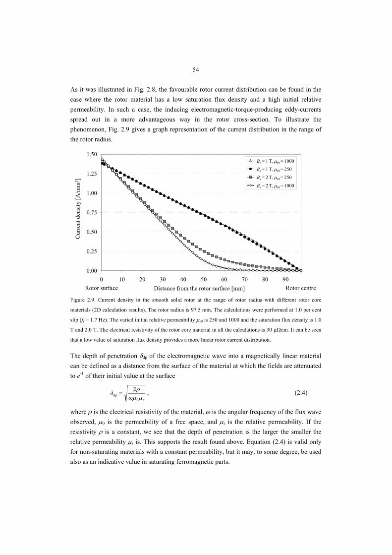
54
As it was illustrated in Fig. 2.8, the favourable rotor current distribution can be found in the case where the rotor material has a low saturation flux density and a high initial relative permeability. In such a case, the inducing electromagnetic-torque-producing eddy-currents spread out in a more advantageous way in the rotor cross-section. To illustrate the phenomenon, Fig. 2.9 gives a graph representation of the current distribution in the range of the rotor radius.
0.00
0.25
0.50
0.75
1.00
1.25
1.50
0 10 20 30 40 50 60 70 80 90Distance from the rotor surface [mm]
Cur
rent
den
sity
[A/m
m ]
1.0 T, Mur 10001.0 T, Mur 2502.0 T, Mur 2502.0 T, Mur 1000
Rotor surface Rotor centre
Cur
rent
den
sity
[A/m
m2 ]
Bs = 2 T, μr0 = 1000
Bs = 2 T, μr0 = 250
Bs = 1 T, μr0 = 250Bs = 1 T, μr0 = 1000
Distance from the rotor surface [mm] Figure 2.9. Current density in the smooth solid rotor at the range of rotor radius with different rotor core
materials (2D calculation results). The rotor radius is 97.5 mm. The calculations were performed at 1.0 per cent
slip (fr = 1.7 Hz). The varied initial relative permeability μr0 is 250 and 1000 and the saturation flux density is 1.0
T and 2.0 T. The electrical resistivity of the rotor core material in all the calculations is 30 µΩcm. It can be seen
that a low value of saturation flux density provides a more linear rotor current distribution.
The depth of penetration δdp of the electromagnetic wave into a magnetically linear material can be defined as a distance from the surface of the material at which the fields are attenuated to e-1 of their initial value at the surface
r0dp
2μμ
ρω
δ = , (2.4)
where ρ is the electrical resistivity of the material, ω is the angular frequency of the flux wave observed, μ0 is the permeability of a free space, and μr is the relative permeability. If the resistivity ρ is a constant, we see that the depth of penetration is the larger the smaller the relative permeability μr is. This supports the result found above. Equation (2.4) is valid only for non-saturating materials with a constant permeability, but it may, to some degree, be used also as an indicative value in saturating ferromagnetic parts.
55
Figure 2.10 illustrates the behaviour of the relative permeability μr of the rotor material in the range of the rotor radius when the saturation flux density of the rotor core material is 1.0 T and 2.0 T and the initial relative permeability is between 250 and 1000. The relative permeability illustrated is obtained from the numerical finite element calculations. The electrical resistivity for all the applied rotor core materials was 30 Ωcm. It can be seen that despite the initial relative permeability μr0 of the rotor core material, the calculated relative permeability μr at the rotor cross-section remains at a low level when the magnetic flux is penetrating into the rotor. The rotor surface magnetic field has a strong intensity and the rotor outer layers are deeply saturated independent of the saturation flux density of the rotor material. This explains why the shape of the magnetization curve becomes almost insignificant when the relative permeability and the penetration depth for the fundamental flux wave are considered at the surface layer of the rotor. This also is in agreement with Agarwal's limiting non-linear theory. When the magnetic flux continues to penetrate deeper into the rotor core, towards the rotor centre, the magnetic field is attenuated and the initial relative permeability μr0 and saturation flux density Bs begins to strongly influence the relative permeability μr and the flux penetration depth. To ensure the flux penetration deep into the centre of the rotor, thereby utilizing the whole rotor cross-section in the electromagnetic torque production, a low-permeability flow path for the fundamental flux wave on its way is required. With a rotor core material having a low saturation flux density, the relative permeability remains naturally low on its way towards the rotor centre, because the magnetic fields in the medium are high enough to operate beyond the linear part of the BH curve. The low permeability of the medium ensures a better penetration depth for the magnetic flux and the rotor currents. The results in Fig. 2.10 illustrate that with a material having a low initial permeability and a low saturation flux density, the behaviour of the permeability is more uniform in the smooth solid rotor. In a case, where the rotor material has a high saturation flux density, the low initial relative permeability becomes favourable. The magnetic fields in the centre part of the rotor are acting in the linear part of the BH curve. The low relative permeability in the linear part of the BH curve ensures a better depth of penetration in the centre part of the rotor. Therefore, the current distribution will be disadvantageous from the electromagnetic torque production point of view, as it was illustrated in Figs. 2.8 and 2.9.
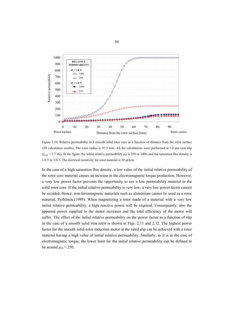
56
Rotor surface Rotor centre
0
100
200
300
400
500
600
700
800
900
1000
0 10 20 30 40 50 60 70 80 90
Distance from the rotor surface [mm]
Rel
ativ
e pe
rmea
bilit
y 1000250
1000
RELATIVE PERMEABILITY
250
Bs = 1.0 T
Bs = 2.0 T1000250
1000
RELATIVE PERMEABILITY
250
Bs = 1.0 T
Bs = 2.0 T
Figure 2.10. Relative permeability in a smooth solid rotor core as a function of distance from the rotor surface
(2D calculation results). The rotor radius is 97.5 mm. All the calculations were performed at 1.0 per cent slip
(frotor = 1.7 Hz). In the figure, the initial relative permeability μr0 is 250 or 1000, and the saturation flux density is
1.0 T or 2.0 T. The electrical resistivity for rotor material is 30 µΩcm.
In the case of a high saturation flux density, a low value of the initial relative permeability of the rotor core material causes an increase in the electromagnetic torque production. However, a very low power factor prevents the opportunity to use a low permeability material in the solid rotor core. If the initial relative permeability is very low, a very low power factor cannot be avoided. Hence, non-ferromagnetic materials such as aluminium cannot be used as a rotor material, Pyrhönen (1989). When magnetizing a rotor made of a material with a very low initial relative permeability, a high reactive power will be required. Consequently, also the apparent power supplied to the motor increases and the total efficiency of the motor will suffer. The effect of the initial relative permeability on the power factor as a function of slip in the case of a smooth solid iron rotor is shown in Figs. 2.11 and 2.12. The highest power factor for the smooth solid-rotor induction motor at the rated slip can be achieved with a rotor material having a high value of initial relative permeability. Similarly, as it is in the case of electromagnetic torque, the lower limit for the initial relative permeability can be defined to be around μr0 = 250.
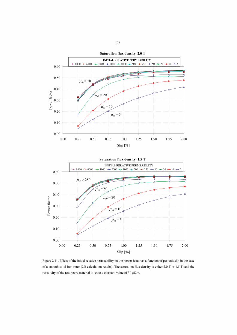
57
0.00
0.10
0.20
0.30
0.40
0.50
0.60
0.00 0.25 0.50 0.75 1.00 1.25 1.50 1.75 2.00
Slip [%]
Pow
er fa
ctor
8000 6000 4000 2000 500 250 50INITIAL RELATIVE PERMEABILITY
1000 20 10 58000 6000 4000 2000 500 250 50INITIAL RELATIVE PERMEABILITY
1000 20 10 5
Saturation flux density 2.0 T
μr0 > 50
μr0 = 20
μr0 = 10
μr0 = 5
0.00
0.10
0.20
0.30
0.40
0.50
0.60
0.00 0.25 0.50 0.75 1.00 1.25 1.50 1.75 2.00
Slip [%]
Pow
er fa
ctor
Saturation flux density 1.5 T
8000 6000 4000 2000 500 250 50INITIAL RELATIVE PERMEABILITY
1000 20 10 58000 6000 4000 2000 500 250 50INITIAL RELATIVE PERMEABILITY
1000 20 10 5
μr0 > 250
μr0 = 5
μr0 = 20
μr0 = 10
μr0 = 50
Figure 2.11. Effect of the initial relative permeability on the power factor as a function of per-unit slip in the case
of a smooth solid iron rotor (2D calculation results). The saturation flux density is either 2.0 T or 1.5 T, and the
resistivity of the rotor core material is set to a constant value of 30 μΩm.
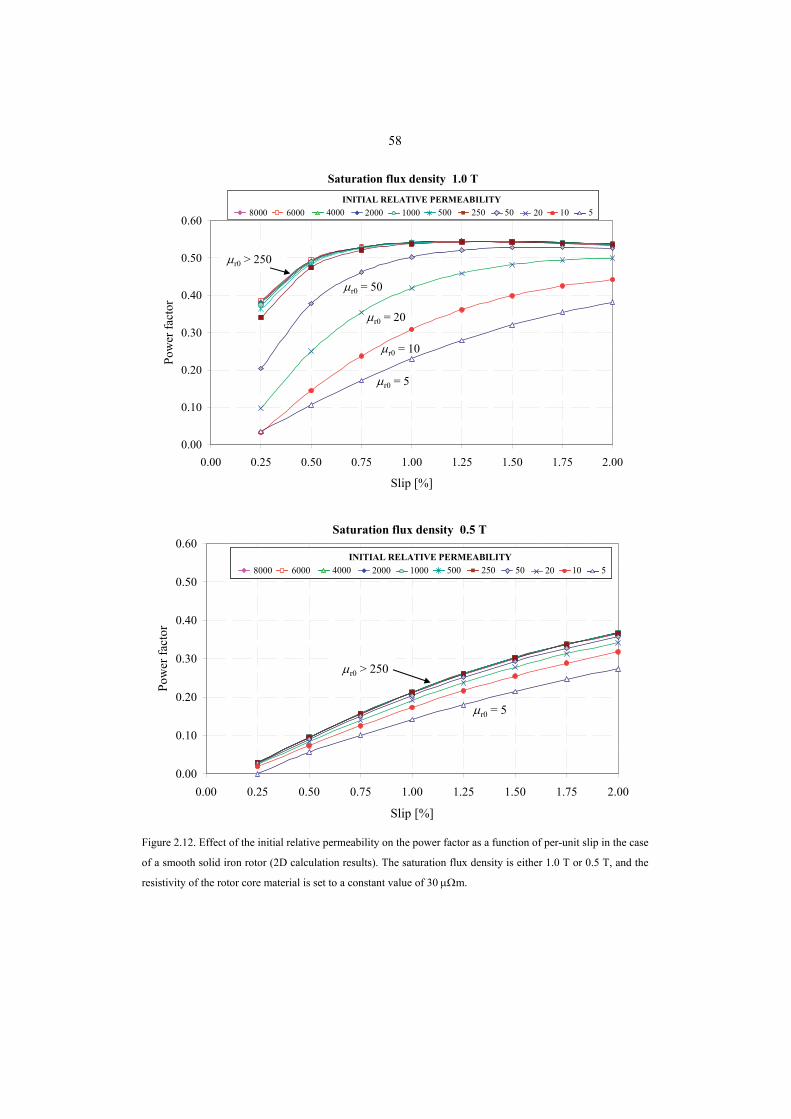
58
0.00
0.10
0.20
0.30
0.40
0.50
0.60
0.00 0.25 0.50 0.75 1.00 1.25 1.50 1.75 2.00
Slip [%]
Pow
er fa
ctor
Saturation flux density 1.0 T
8000 6000 4000 2000 500 250 50INITIAL RELATIVE PERMEABILITY
1000 20 10 58000 6000 4000 2000 500 250 50INITIAL RELATIVE PERMEABILITY
1000 20 10 5
μr0 > 250
μr0 = 5
μr0 = 10
μr0 = 50
μr0 = 20
0.00
0.10
0.20
0.30
0.40
0.50
0.60
0.00 0.25 0.50 0.75 1.00 1.25 1.50 1.75 2.00
Slip [%]
Pow
er fa
ctor
Saturation flux density 0.5 T
8000 6000 4000 2000 500 250 50INITIAL RELATIVE PERMEABILITY
1000 20 10 58000 6000 4000 2000 500 250 50INITIAL RELATIVE PERMEABILITY
1000 20 10 5
μr0 > 250
μr0 = 5
Figure 2.12. Effect of the initial relative permeability on the power factor as a function of per-unit slip in the case
of a smooth solid iron rotor (2D calculation results). The saturation flux density is either 1.0 T or 0.5 T, and the
resistivity of the rotor core material is set to a constant value of 30 μΩm.
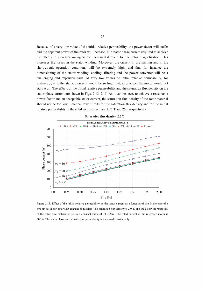
59
Because of a very low value of the initial relative permeability, the power factor will suffer and the apparent power of the rotor will increase. The stator phase current required to achieve the rated slip increases owing to the increased demand for the rotor magnetization. This increases the losses in the stator winding. Moreover, the current in the starting and in the short-circuit operation conditions will be extremely high, and thus for instance the dimensioning of the stator winding, cooling, filtering and the power converter will be a challenging and expensive task. At very low values of initial relative permeability, for instance µr = 5, the start-up current would be so high that, in practice, the motor would not start at all. The effects of the initial relative permeability and the saturation flux density on the stator phase current are shown in Figs. 2.13–2.15. As it can be seen, to achieve a reasonable power factor and an acceptable stator current, the saturation flux density of the rotor material should not be too low. Practical lower limits for the saturation flux density and for the initial relative permeability in the solid rotor studied are 1.25 T and 250, respectively.
0
100
200
300
400
500
600
700
0.00 0.25 0.50 0.75 1.00 1.25 1.50 1.75 2.00
Slip [%]
Phas
e cu
rren
t [A
]
8000 6000 4000 2000 500 250 50INITIAL RELATIVE PERMEABILITY
1000 20 10 58000 6000 4000 2000 500 250 50INITIAL RELATIVE PERMEABILITY
1000 20 10 5
Saturation flux density 2.0 T
μr0 > 250
μr0 = 5
μr0 = 10
μr0 = 20
μr0 = 50
Figure 2.13. Effect of the initial relative permeability on the stator current as a function of slip in the case of a
smooth solid iron rotor (2D calculation results). The saturation flux density is 2.0 T, and the electrical resistivity
of the rotor core material is set to a constant value of 30 μΩcm. The rated current of the reference motor is
300 A. The stator phase current with low permeability is increased considerably.
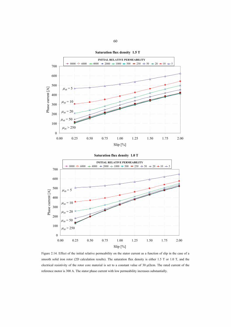
60
0
100
200
300
400
500
600
700
0.00 0.25 0.50 0.75 1.00 1.25 1.50 1.75 2.00
Slip [%]
Phas
e cu
rren
t [A
]
8000 6000 4000 2000 500 250 50INITIAL RELATIVE PERMEABILITY
1000 20 10 58000 6000 4000 2000 500 250 50INITIAL RELATIVE PERMEABILITY
1000 20 10 5
Saturation flux density 1.5 T
μr0 > 250
μr0 = 5
μr0 = 10
μr0 = 20
μr0 = 50
0
100
200
300
400
500
600
700
0.00 0.25 0.50 0.75 1.00 1.25 1.50 1.75 2.00
Slip [%]
Phas
e cu
rren
t [A
]
8000 6000 4000 2000 500 250 50INITIAL RELATIVE PERMEABILITY
1000 20 10 58000 6000 4000 2000 500 250 50INITIAL RELATIVE PERMEABILITY
1000 20 10 5
Saturation flux density 1.0 T
μr0 > 250
μr0 = 5
μr0 = 10
μr0 = 20
μr0 = 50
Figure 2.14. Effect of the initial relative permeability on the stator current as a function of slip in the case of a
smooth solid iron rotor (2D calculation results). The saturation flux density is either 1.5 T or 1.0 T, and the
electrical resistivity of the rotor core material is set to a constant value of 30 μΩcm. The rated current of the
reference motor is 300 A. The stator phase current with low permeability increases substantially.
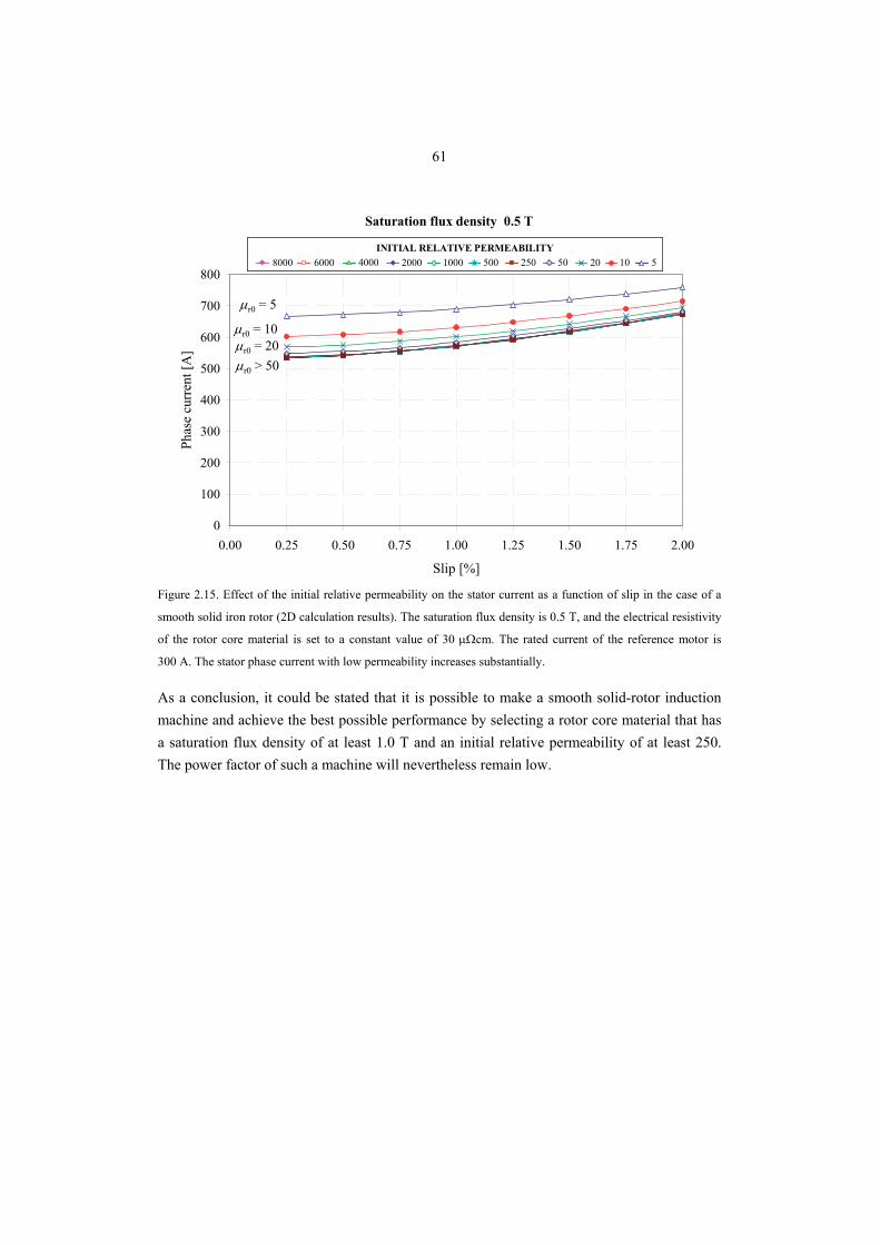
61
0
100
200
300
400
500
600
700
800
0.00 0.25 0.50 0.75 1.00 1.25 1.50 1.75 2.00
Slip [%]
Phas
e cu
rren
t [A
]
8000 6000 4000 2000 500 250 50INITIAL RELATIVE PERMEABILITY
1000 20 10 58000 6000 4000 2000 500 250 50INITIAL RELATIVE PERMEABILITY
1000 20 10 5
Saturation flux density 0.5 T
μr0 > 50
μr0 = 5
μr0 = 10μr0 = 20
Figure 2.15. Effect of the initial relative permeability on the stator current as a function of slip in the case of a
smooth solid iron rotor (2D calculation results). The saturation flux density is 0.5 T, and the electrical resistivity
of the rotor core material is set to a constant value of 30 μΩcm. The rated current of the reference motor is
300 A. The stator phase current with low permeability increases substantially.
As a conclusion, it could be stated that it is possible to make a smooth solid-rotor induction machine and achieve the best possible performance by selecting a rotor core material that has a saturation flux density of at least 1.0 T and an initial relative permeability of at least 250. The power factor of such a machine will nevertheless remain low.
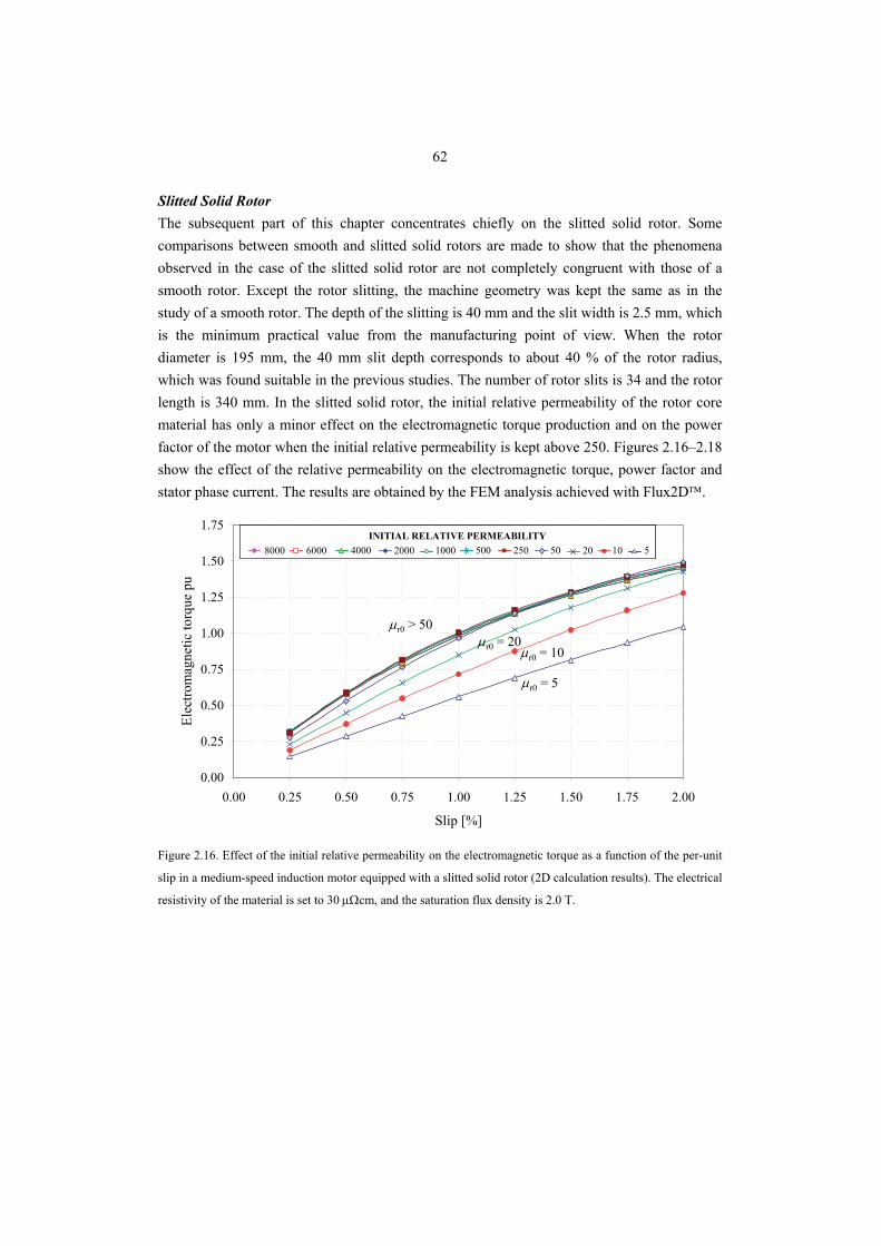
62
Slitted Solid Rotor The subsequent part of this chapter concentrates chiefly on the slitted solid rotor. Some comparisons between smooth and slitted solid rotors are made to show that the phenomena observed in the case of the slitted solid rotor are not completely congruent with those of a smooth rotor. Except the rotor slitting, the machine geometry was kept the same as in the study of a smooth rotor. The depth of the slitting is 40 mm and the slit width is 2.5 mm, which is the minimum practical value from the manufacturing point of view. When the rotor diameter is 195 mm, the 40 mm slit depth corresponds to about 40 % of the rotor radius, which was found suitable in the previous studies. The number of rotor slits is 34 and the rotor length is 340 mm. In the slitted solid rotor, the initial relative permeability of the rotor core material has only a minor effect on the electromagnetic torque production and on the power factor of the motor when the initial relative permeability is kept above 250. Figures 2.16–2.18 show the effect of the relative permeability on the electromagnetic torque, power factor and stator phase current. The results are obtained by the FEM analysis achieved with Flux2D™.
0.00
0.25
0.50
0.75
1.00
1.25
1.50
1.75
0.00 0.25 0.50 0.75 1.00 1.25 1.50 1.75 2.00
Slip [%]
Elec
trom
agne
tic to
rque
pu
8000 6000 4000 2000 500 250 50INITIAL RELATIVE PERMEABILITY
1000 20 10 58000 6000 4000 2000 500 250 50INITIAL RELATIVE PERMEABILITY
1000 20 10 5
μr0 > 50
μr0 = 5
μr0 = 10μr0 = 20
Figure 2.16. Effect of the initial relative permeability on the electromagnetic torque as a function of the per-unit
slip in a medium-speed induction motor equipped with a slitted solid rotor (2D calculation results). The electrical
resistivity of the material is set to 30 μΩcm, and the saturation flux density is 2.0 T.
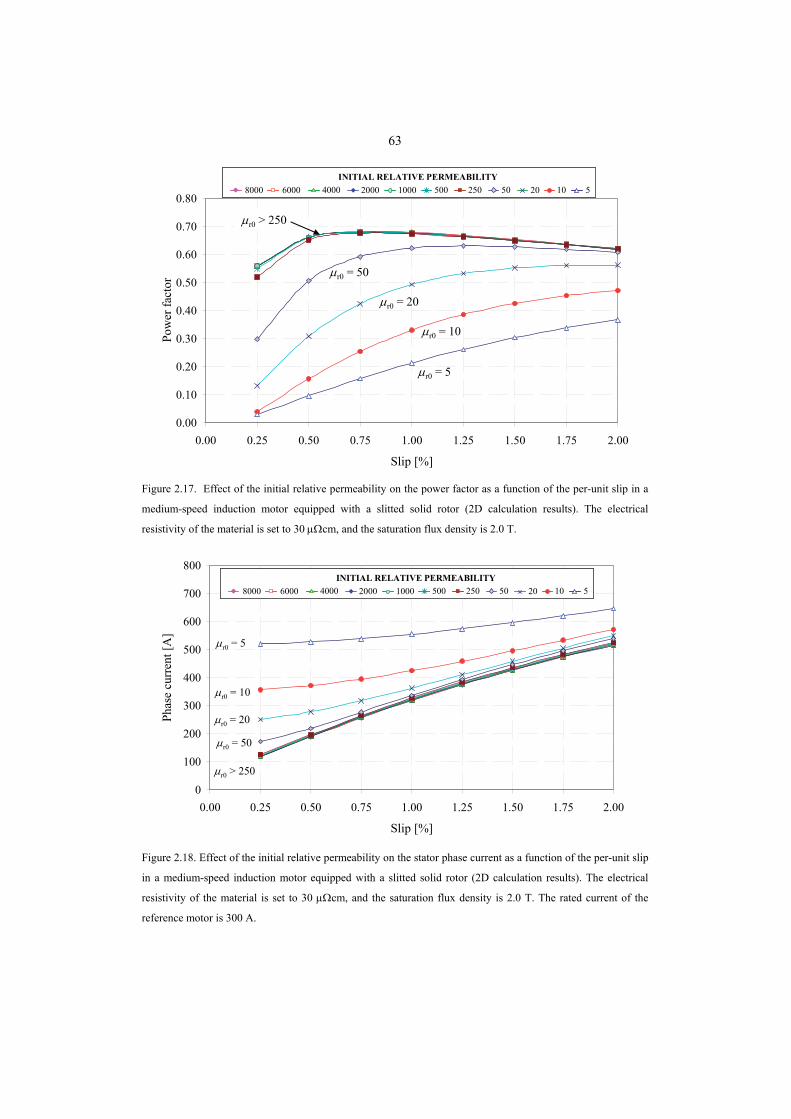
63
0.00
0.10
0.20
0.30
0.40
0.50
0.60
0.70
0.80
0.00 0.25 0.50 0.75 1.00 1.25 1.50 1.75 2.00
Slip [%]
Pow
er fa
ctor
8000 6000 4000 2000 500 250 50INITIAL RELATIVE PERMEABILITY
1000 20 10 58000 6000 4000 2000 500 250 50INITIAL RELATIVE PERMEABILITY
1000 20 10 5
μr0 > 250
μr0 = 5
μr0 = 10
μr0 = 20
μr0 = 50
Figure 2.17. Effect of the initial relative permeability on the power factor as a function of the per-unit slip in a
medium-speed induction motor equipped with a slitted solid rotor (2D calculation results). The electrical
resistivity of the material is set to 30 μΩcm, and the saturation flux density is 2.0 T.
0
100
200
300
400
500
600
700
800
0.00 0.25 0.50 0.75 1.00 1.25 1.50 1.75 2.00
Slip [%]
Phas
e cu
rren
t [A
]
8000 6000 4000 2000 500 250 50INITIAL RELATIVE PERMEABILITY
1000 20 10 58000 6000 4000 2000 500 250 50INITIAL RELATIVE PERMEABILITY
1000 20 10 5
μr0 > 250
μr0 = 5
μr0 = 10
μr0 = 20
μr0 = 50
Figure 2.18. Effect of the initial relative permeability on the stator phase current as a function of the per-unit slip
in a medium-speed induction motor equipped with a slitted solid rotor (2D calculation results). The electrical
resistivity of the material is set to 30 μΩcm, and the saturation flux density is 2.0 T. The rated current of the
reference motor is 300 A.
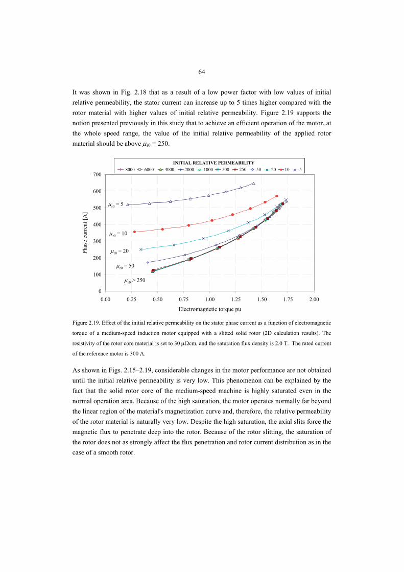
64
It was shown in Fig. 2.18 that as a result of a low power factor with low values of initial relative permeability, the stator current can increase up to 5 times higher compared with the rotor material with higher values of initial relative permeability. Figure 2.19 supports the notion presented previously in this study that to achieve an efficient operation of the motor, at the whole speed range, the value of the initial relative permeability of the applied rotor material should be above μr0 = 250.
0
100
200
300
400
500
600
700
0.00 0.25 0.50 0.75 1.00 1.25 1.50 1.75 2.00
Electromagnetic torque pu
Phas
e cu
rren
t [A
]
8000 6000 4000 2000 500 250 50INITIAL RELATIVE PERMEABILITY
1000 20 10 58000 6000 4000 2000 500 250 50INITIAL RELATIVE PERMEABILITY
1000 20 10 5
μr0 > 250
μr0 = 5
μr0 = 10
μr0 = 20
μr0 = 50
Figure 2.19. Effect of the initial relative permeability on the stator phase current as a function of electromagnetic
torque of a medium-speed induction motor equipped with a slitted solid rotor (2D calculation results). The
resistivity of the rotor core material is set to 30 μΩcm, and the saturation flux density is 2.0 T. The rated current
of the reference motor is 300 A.
As shown in Figs. 2.15–2.19, considerable changes in the motor performance are not obtained until the initial relative permeability is very low. This phenomenon can be explained by the fact that the solid rotor core of the medium-speed machine is highly saturated even in the normal operation area. Because of the high saturation, the motor operates normally far beyond the linear region of the material's magnetization curve and, therefore, the relative permeability of the rotor material is naturally very low. Despite the high saturation, the axial slits force the magnetic flux to penetrate deep into the rotor. Because of the rotor slitting, the saturation of the rotor does not as strongly affect the flux penetration and rotor current distribution as in the case of a smooth rotor.
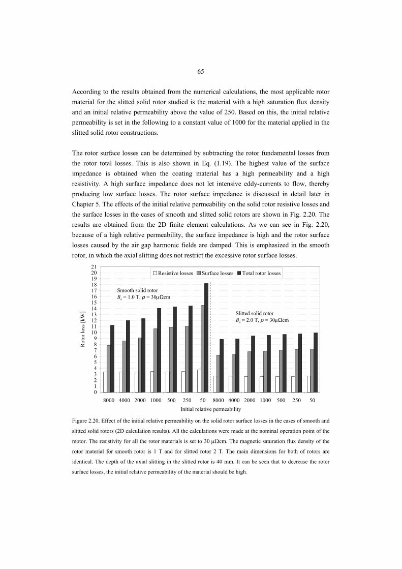
65
According to the results obtained from the numerical calculations, the most applicable rotor material for the slitted solid rotor studied is the material with a high saturation flux density and an initial relative permeability above the value of 250. Based on this, the initial relative permeability is set in the following to a constant value of 1000 for the material applied in the slitted solid rotor constructions. The rotor surface losses can be determined by subtracting the rotor fundamental losses from the rotor total losses. This is also shown in Eq. (1.19). The highest value of the surface impedance is obtained when the coating material has a high permeability and a high resistivity. A high surface impedance does not let intensive eddy-currents to flow, thereby producing low surface losses. The rotor surface impedance is discussed in detail later in Chapter 5. The effects of the initial relative permeability on the solid rotor resistive losses and the surface losses in the cases of smooth and slitted solid rotors are shown in Fig. 2.20. The results are obtained from the 2D finite element calculations. As we can see in Fig. 2.20, because of a high relative permeability, the surface impedance is high and the rotor surface losses caused by the air gap harmonic fields are damped. This is emphasized in the smooth rotor, in which the axial slitting does not restrict the excessive rotor surface losses.
0123456789
101112131415161718192021
8000 4000 2000 1000 500 250 50 8000 4000 2000 1000 500 250 50Initial relative permeability
Rot
or lo
ss [k
W]
Resistive losses Surface losses Total rotor losses
Slitted solid rotorBs = 2.0 T, ρ = 30μΩcm
Smooth solid rotorBs = 1.0 T, ρ = 30μΩcm
Figure 2.20. Effect of the initial relative permeability on the solid rotor surface losses in the cases of smooth and
slitted solid rotors (2D calculation results). All the calculations were made at the nominal operation point of the
motor. The resistivity for all the rotor materials is set to 30 μΩcm. The magnetic saturation flux density of the
rotor material for smooth rotor is 1 T and for slitted rotor 2 T. The main dimensions for both of rotors are
identical. The depth of the axial slitting in the slitted rotor is 40 mm. It can be seen that to decrease the rotor
surface losses, the initial relative permeability of the material should be high.
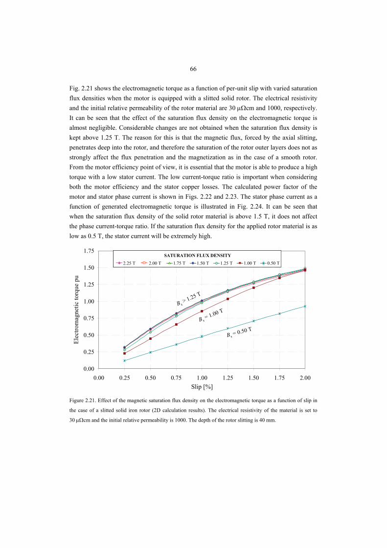
66
Fig. 2.21 shows the electromagnetic torque as a function of per-unit slip with varied saturation flux densities when the motor is equipped with a slitted solid rotor. The electrical resistivity and the initial relative permeability of the rotor material are 30 μΩcm and 1000, respectively. It can be seen that the effect of the saturation flux density on the electromagnetic torque is almost negligible. Considerable changes are not obtained when the saturation flux density is kept above 1.25 T. The reason for this is that the magnetic flux, forced by the axial slitting, penetrates deep into the rotor, and therefore the saturation of the rotor outer layers does not as strongly affect the flux penetration and the magnetization as in the case of a smooth rotor. From the motor efficiency point of view, it is essential that the motor is able to produce a high torque with a low stator current. The low current-torque ratio is important when considering both the motor efficiency and the stator copper losses. The calculated power factor of the motor and stator phase current is shown in Figs. 2.22 and 2.23. The stator phase current as a function of generated electromagnetic torque is illustrated in Fig. 2.24. It can be seen that when the saturation flux density of the solid rotor material is above 1.5 T, it does not affect the phase current-torque ratio. If the saturation flux density for the applied rotor material is as low as 0.5 T, the stator current will be extremely high.
0.00
0.25
0.50
0.75
1.00
1.25
1.50
1.75
0.00 0.25 0.50 0.75 1.00 1.25 1.50 1.75 2.00Slip [%]
Elec
trom
agne
tic to
rque
pu
2.25 T 2.00 T 1.75 T 1.50 T 1.00 T 0.50 T
SATURATION FLUX DENSITY
1.25 T2.25 T 2.00 T 1.75 T 1.50 T 1.00 T 0.50 T
SATURATION FLUX DENSITY
1.25 T
B s> 1.25 T
B s = 0.50 T
B s= 1.00 T
Figure 2.21. Effect of the magnetic saturation flux density on the electromagnetic torque as a function of slip in
the case of a slitted solid iron rotor (2D calculation results). The electrical resistivity of the material is set to
30 μΩcm and the initial relative permeability is 1000. The depth of the rotor slitting is 40 mm.
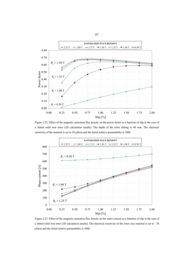
67
0.00
0.10
0.20
0.30
0.40
0.50
0.60
0.70
0.80
0.00 0.25 0.50 0.75 1.00 1.25 1.50 1.75 2.00Slip [%]
Pow
er fa
ctor
2.25 T 2.00 T 1.75 T 1.50 T 1.00 T 0.50 T
SATURATION FLUX DENSITY
1.25 T2.25 T 2.00 T 1.75 T 1.50 T 1.00 T 0.50 T
SATURATION FLUX DENSITY
1.25 T
Bs > 1.50 T
Bs = 0.50 T
Bs = 1.00 T
Bs = 1.25 T
Figure 2.22. Effect of the magnetic saturation flux density on the power factor as a function of slip in the case of
a slitted solid iron rotor (2D calculation results). The depth of the rotor slitting is 40 mm. The electrical
resistivity of the material is set to 30 μΩcm and the initial relative permeability is 1000.
0
100
200
300
400
500
600
700
800
0.00 0.25 0.50 0.75 1.00 1.25 1.50 1.75 2.00Slip [%]
Phas
e cu
rren
t [A
]
2.25 T 2.00 T 1.75 T 1.50 T 1.00 T 0.50 T
SATURATION FLUX DENSITY
1.25 T2.25 T 2.00 T 1.75 T 1.50 T 1.00 T 0.50 T
SATURATION FLUX DENSITY
1.25 T
Bs > 1.25 T
Bs = 0.50 T
Bs = 1.00 T
Figure 2.23. Effect of the magnetic saturation flux density on the stator current as a function of slip in the case of
a slitted solid iron rotor (2D calculation results). The electrical resistivity of the rotor core material is set to 30
μΩcm and the initial relative permeability is 1000.
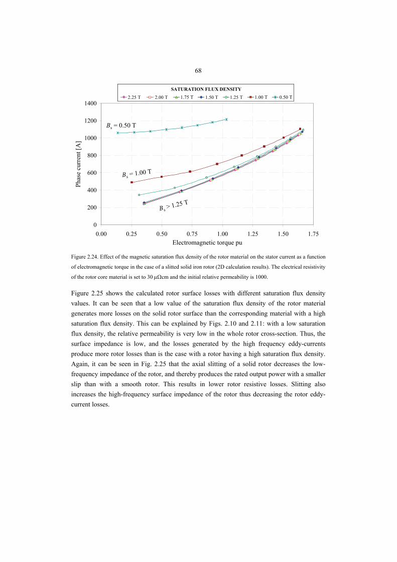
68
0
200
400
600
800
1000
1200
1400
0.00 0.25 0.50 0.75 1.00 1.25 1.50 1.75Electromagnetic torque pu
Phas
e cu
rren
t [A
]
2.25 T 2.00 T 1.75 T 1.50 T 1.00 T 0.50 T
SATURATION FLUX DENSITY
1.25 T2.25 T 2.00 T 1.75 T 1.50 T 1.00 T 0.50 T
SATURATION FLUX DENSITY
1.25 T
Bs > 1.25 T
Bs = 0.50 T
Bs = 1.00 T
Figure 2.24. Effect of the magnetic saturation flux density of the rotor material on the stator current as a function
of electromagnetic torque in the case of a slitted solid iron rotor (2D calculation results). The electrical resistivity
of the rotor core material is set to 30 μΩcm and the initial relative permeability is 1000.
Figure 2.25 shows the calculated rotor surface losses with different saturation flux density values. It can be seen that a low value of the saturation flux density of the rotor material generates more losses on the solid rotor surface than the corresponding material with a high saturation flux density. This can be explained by Figs. 2.10 and 2.11: with a low saturation flux density, the relative permeability is very low in the whole rotor cross-section. Thus, the surface impedance is low, and the losses generated by the high frequency eddy-currents produce more rotor losses than is the case with a rotor having a high saturation flux density. Again, it can be seen in Fig. 2.25 that the axial slitting of a solid rotor decreases the low-frequency impedance of the rotor, and thereby produces the rated output power with a smaller slip than with a smooth rotor. This results in lower rotor resistive losses. Slitting also increases the high-frequency surface impedance of the rotor thus decreasing the rotor eddy-current losses.
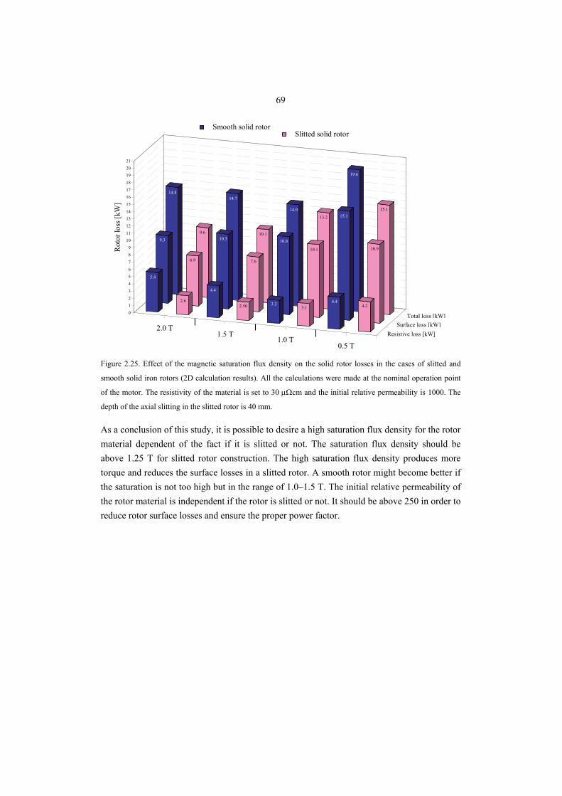
69
Resistive loss
Surface
To
0.5 T, slitted0.5 T, smooth1.0 T, slitted1.0 T, smooth1.5 T, slitted1.5 T, smooth2.0 T, slitted2.0 T, smooth
14.8
9.3
5.4
9.6
6.9
2.6
14.7
10.3
4.4
10.1
7.6
2.56
14.0
10.8
3.2
13.2
10.1
3.1
19.6
15.1
4.4
15.1
10.9
4.20123456789
101112131415161718192021
2.0 T1.5 T
1.0 T0.5 T
Total loss [kW]Surface loss [kW]
Resistive loss [kW]
Rot
or lo
ss [k
W]
Slitted solid rotorSmooth solid rotor
Figure 2.25. Effect of the magnetic saturation flux density on the solid rotor losses in the cases of slitted and
smooth solid iron rotors (2D calculation results). All the calculations were made at the nominal operation point
of the motor. The resistivity of the material is set to 30 μΩcm and the initial relative permeability is 1000. The
depth of the axial slitting in the slitted rotor is 40 mm.
As a conclusion of this study, it is possible to desire a high saturation flux density for the rotor material dependent of the fact if it is slitted or not. The saturation flux density should be above 1.25 T for slitted rotor construction. The high saturation flux density produces more torque and reduces the surface losses in a slitted rotor. A smooth rotor might become better if the saturation is not too high but in the range of 1.0–1.5 T. The initial relative permeability of the rotor material is independent if the rotor is slitted or not. It should be above 250 in order to reduce rotor surface losses and ensure the proper power factor.
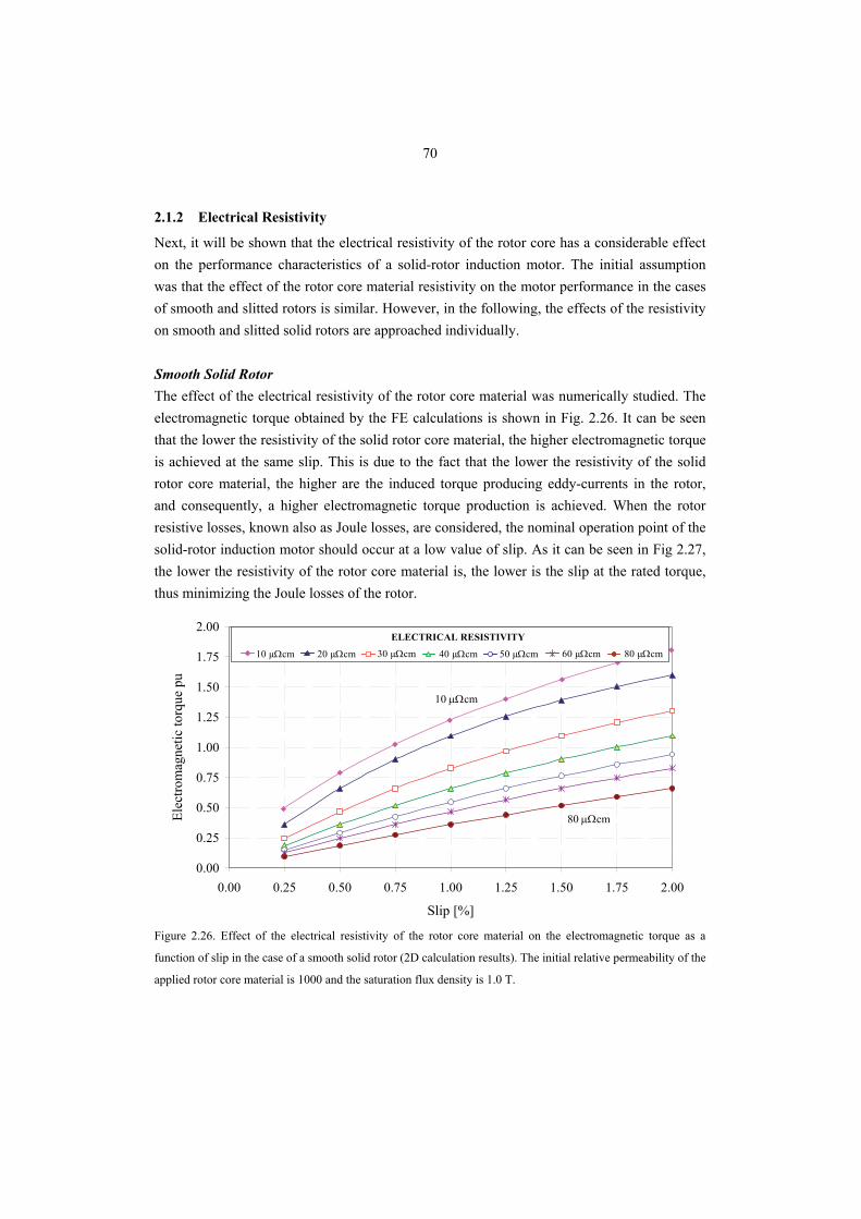
70
2.1.2 Electrical Resistivity
Next, it will be shown that the electrical resistivity of the rotor core has a considerable effect on the performance characteristics of a solid-rotor induction motor. The initial assumption was that the effect of the rotor core material resistivity on the motor performance in the cases of smooth and slitted rotors is similar. However, in the following, the effects of the resistivity on smooth and slitted solid rotors are approached individually. Smooth Solid Rotor The effect of the electrical resistivity of the rotor core material was numerically studied. The electromagnetic torque obtained by the FE calculations is shown in Fig. 2.26. It can be seen that the lower the resistivity of the solid rotor core material, the higher electromagnetic torque is achieved at the same slip. This is due to the fact that the lower the resistivity of the solid rotor core material, the higher are the induced torque producing eddy-currents in the rotor, and consequently, a higher electromagnetic torque production is achieved. When the rotor resistive losses, known also as Joule losses, are considered, the nominal operation point of the solid-rotor induction motor should occur at a low value of slip. As it can be seen in Fig 2.27, the lower the resistivity of the rotor core material is, the lower is the slip at the rated torque, thus minimizing the Joule losses of the rotor.
0.00
0.25
0.50
0.75
1.00
1.25
1.50
1.75
2.00
0.00 0.25 0.50 0.75 1.00 1.25 1.50 1.75 2.00
Slip [%]
Elec
trom
agne
tic to
rque
pu
10 µΩcm 20 µΩcm 30 µΩcm 40 µΩcm 60 µΩcm 80 µΩcm
ELECTRICAL RESISTIVITY
50 µΩcm
80 μΩcm
10 μΩcm
Figure 2.26. Effect of the electrical resistivity of the rotor core material on the electromagnetic torque as a
function of slip in the case of a smooth solid rotor (2D calculation results). The initial relative permeability of the
applied rotor core material is 1000 and the saturation flux density is 1.0 T.
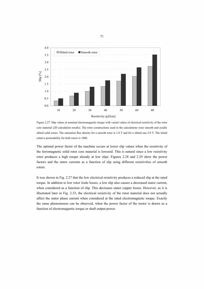
71
0.0
0.5
1.0
1.5
2.0
2.5
3.0
3.5
4.0
10 20 30 40 50 60 80
Resistivity []
Slip
[%]
Slitted rotor Smooth rotor
Resistivity [μΩcm] Figure 2.27. Slip values at nominal electromagnetic torque with varied values of electrical resistivity of the rotor
core material (2D calculation results). The rotor constructions used in the calculations were smooth and axially
slitted solid rotors. The saturation flux density for a smooth rotor is 1.0 T and for a slitted one 2.0 T. The initial
relative permeability for both rotors is 1000.
The optimal power factor of the machine occurs at lower slip values when the resistivity of the ferromagnetic solid rotor core material is lowered. This is natural since a low resistivity rotor produces a high torque already at low slips. Figures 2.28 and 2.29 show the power factors and the stator currents as a function of slip using different resistivities of smooth rotors. It was shown in Fig. 2.27 that the low electrical resistivity produces a reduced slip at the rated torque. In addition to low rotor Joule losses, a low slip also causes a decreased stator current, when considered as a function of slip. This decreases stator copper losses. However, as it is illustrated later in Fig. 2.33, the electrical resistivity of the rotor material does not actually affect the stator phase current when considered at the rated electromagnetic torque. Exactly the same phenomenon can be observed, when the power factor of the motor is drawn as a function of electromagnetic torque or shaft output power.
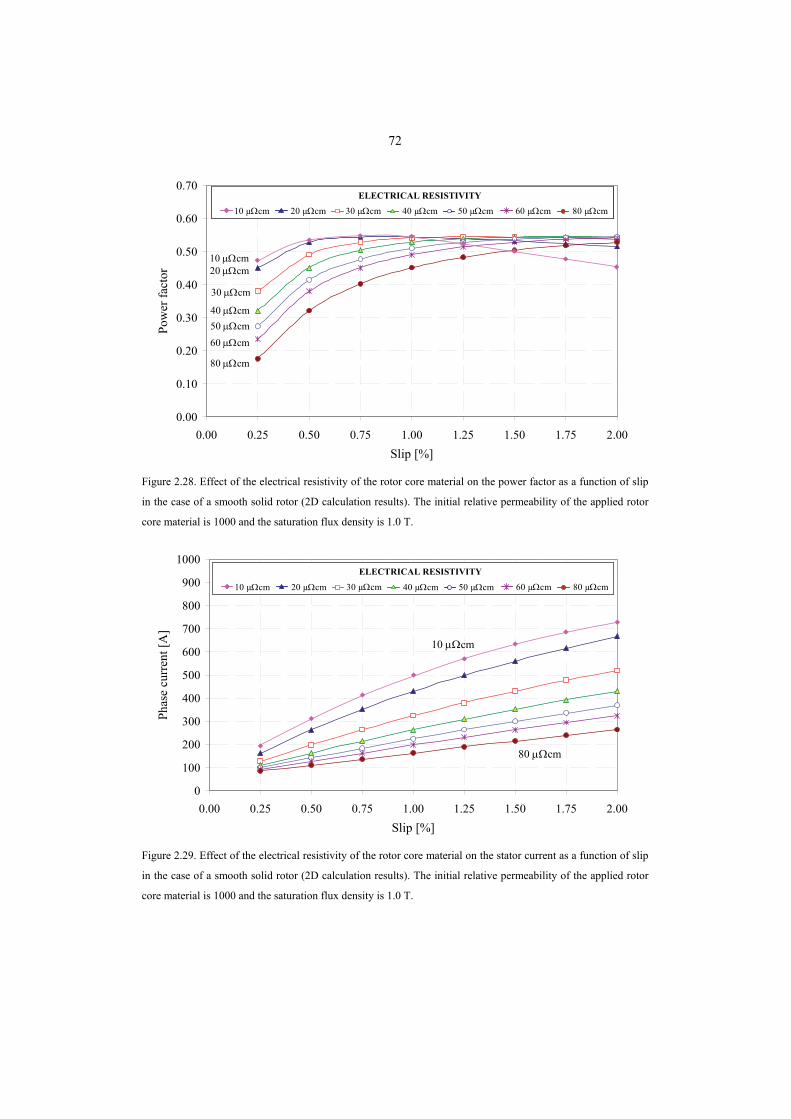
72
0.00
0.10
0.20
0.30
0.40
0.50
0.60
0.70
0.00 0.25 0.50 0.75 1.00 1.25 1.50 1.75 2.00Slip [%]
Pow
er fa
ctor
10 µΩcm 20 µΩcm 30 µΩcm 40 µΩcm 60 µΩcm 80 µΩcm
ELECTRICAL RESISTIVITY
50 µΩcm10 µΩcm 20 µΩcm 30 µΩcm 40 µΩcm 60 µΩcm 80 µΩcm
ELECTRICAL RESISTIVITY
50 µΩcm
30 μΩcm
40 μΩcm50 μΩcm60 μΩcm
80 μΩcm
20 μΩcm10 μΩcm
Figure 2.28. Effect of the electrical resistivity of the rotor core material on the power factor as a function of slip
in the case of a smooth solid rotor (2D calculation results). The initial relative permeability of the applied rotor
core material is 1000 and the saturation flux density is 1.0 T.
0
100
200
300
400
500
600
700
800
900
1000
0.00 0.25 0.50 0.75 1.00 1.25 1.50 1.75 2.00Slip [%]
Phas
e cu
rren
t [A
]
10 µΩcm 20 µΩcm 30 µΩcm 40 µΩcm 60 µΩcm 80 µΩcm
ELECTRICAL RESISTIVITY
50 µΩcm10 µΩcm 20 µΩcm 30 µΩcm 40 µΩcm 60 µΩcm 80 µΩcm
ELECTRICAL RESISTIVITY
50 µΩcm
80 μΩcm
10 μΩcm
Figure 2.29. Effect of the electrical resistivity of the rotor core material on the stator current as a function of slip
in the case of a smooth solid rotor (2D calculation results). The initial relative permeability of the applied rotor
core material is 1000 and the saturation flux density is 1.0 T.
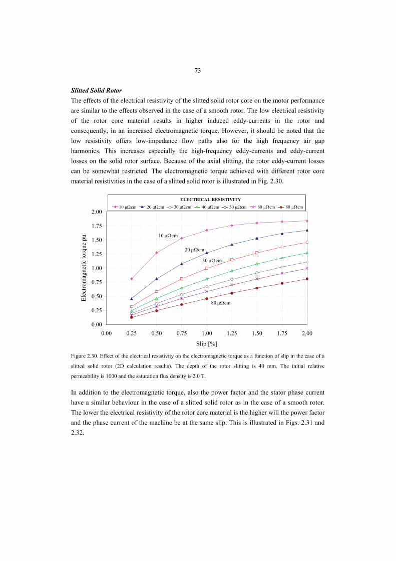
73
Slitted Solid Rotor The effects of the electrical resistivity of the slitted solid rotor core on the motor performance are similar to the effects observed in the case of a smooth rotor. The low electrical resistivity of the rotor core material results in higher induced eddy-currents in the rotor and consequently, in an increased electromagnetic torque. However, it should be noted that the low resistivity offers low-impedance flow paths also for the high frequency air gap harmonics. This increases especially the high-frequency eddy-currents and eddy-current losses on the solid rotor surface. Because of the axial slitting, the rotor eddy-current losses can be somewhat restricted. The electromagnetic torque achieved with different rotor core material resistivities in the case of a slitted solid rotor is illustrated in Fig. 2.30.
0.00
0.25
0.50
0.75
1.00
1.25
1.50
1.75
2.00
0.00 0.25 0.50 0.75 1.00 1.25 1.50 1.75 2.00
Slip [%]
Elec
trom
agne
tic to
rque
pu
10 µΩcm 20 µΩcm 30 µΩcm 40 µΩcm 60 µΩcm 80 µΩcmELECTRICAL RESISTIVITY
50 µΩcm10 µΩcm 20 µΩcm 30 µΩcm 40 µΩcm 60 µΩcm 80 µΩcmELECTRICAL RESISTIVITY
50 µΩcm
10 μΩcm
30 μΩcm
80 μΩcm
20 μΩcm
Figure 2.30. Effect of the electrical resistivity on the electromagnetic torque as a function of slip in the case of a
slitted solid rotor (2D calculation results). The depth of the rotor slitting is 40 mm. The initial relative
permeability is 1000 and the saturation flux density is 2.0 T.
In addition to the electromagnetic torque, also the power factor and the stator phase current have a similar behaviour in the case of a slitted solid rotor as in the case of a smooth rotor. The lower the electrical resistivity of the rotor core material is the higher will the power factor and the phase current of the machine be at the same slip. This is illustrated in Figs. 2.31 and 2.32.
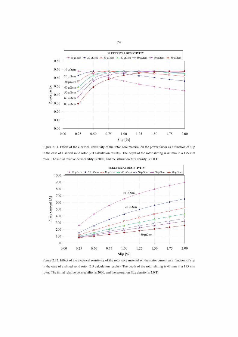
74
0.00
0.10
0.20
0.30
0.40
0.50
0.60
0.70
0.80
0.00 0.25 0.50 0.75 1.00 1.25 1.50 1.75 2.00Slip [%]
Pow
er fa
ctor
10 µΩcm 20 µΩcm 30 µΩcm 40 µΩcm 60 µΩcm 80 µΩcmELECTRICAL RESISTIVITY
50 µΩcm10 µΩcm 20 µΩcm 30 µΩcm 40 µΩcm 60 µΩcm 80 µΩcmELECTRICAL RESISTIVITY
50 µΩcm
10 μΩcm
30 μΩcm
40 μΩcm50 μΩcm
60 μΩcm
80 μΩcm
20 μΩcm
Figure 2.31. Effect of the electrical resistivity of the rotor core material on the power factor as a function of slip
in the case of a slitted solid rotor (2D calculation results). The depth of the rotor slitting is 40 mm in a 195 mm
rotor. The initial relative permeability is 2000, and the saturation flux density is 2.0 T.
0
100
200
300
400
500
600
700
800
900
1000
0.00 0.25 0.50 0.75 1.00 1.25 1.50 1.75 2.00Slip [%]
Phas
e cu
rren
t [A
]
10 µΩcm 20 µΩcm 30 µΩcm 40 µΩcm 60 µΩcm 80 µΩcmELECTRICAL RESISTIVITY
50 µΩcm10 µΩcm 20 µΩcm 30 µΩcm 40 µΩcm 60 µΩcm 80 µΩcmELECTRICAL RESISTIVITY
50 µΩcm
10 μΩcm
80 μΩcm
20 μΩcm
Figure 2.32. Effect of the electrical resistivity of the rotor core material on the stator current as a function of slip
in the case of a slitted solid rotor (2D calculation results). The depth of the rotor slitting is 40 mm in a 195 mm
rotor. The initial relative permeability is 2000, and the saturation flux density is 2.0 T.
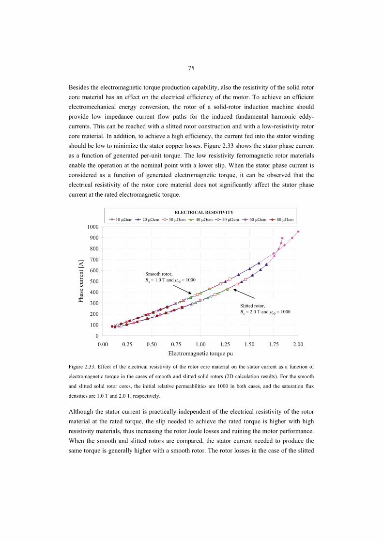
75
Besides the electromagnetic torque production capability, also the resistivity of the solid rotor core material has an effect on the electrical efficiency of the motor. To achieve an efficient electromechanical energy conversion, the rotor of a solid-rotor induction machine should provide low impedance current flow paths for the induced fundamental harmonic eddy-currents. This can be reached with a slitted rotor construction and with a low-resistivity rotor core material. In addition, to achieve a high efficiency, the current fed into the stator winding should be low to minimize the stator copper losses. Figure 2.33 shows the stator phase current as a function of generated per-unit torque. The low resistivity ferromagnetic rotor materials enable the operation at the nominal point with a lower slip. When the stator phase current is considered as a function of generated electromagnetic torque, it can be observed that the electrical resistivity of the rotor core material does not significantly affect the stator phase current at the rated electromagnetic torque.
0
100
200
300
400
500
600
700
800
900
1000
0.00 0.25 0.50 0.75 1.00 1.25 1.50 1.75 2.00Electromagnetic torque pu
Phas
e cu
rren
t [A
]
10 µΩcm 20 µΩcm 30 µΩcm 40 µΩcm 60 µΩcm 80 µΩcmELECTRICAL RESISTIVITY
50 µΩcm10 µΩcm 20 µΩcm 30 µΩcm 40 µΩcm 60 µΩcm 80 µΩcmELECTRICAL RESISTIVITY
50 µΩcm
Slitted rotor,Bs = 2.0 T and μr0 = 1000
Smooth rotor,Bs = 1.0 T and μr0 = 1000
Figure 2.33. Effect of the electrical resistivity of the rotor core material on the stator current as a function of
electromagnetic torque in the cases of smooth and slitted solid rotors (2D calculation results). For the smooth
and slitted solid rotor cores, the initial relative permeabilities are 1000 in both cases, and the saturation flux
densities are 1.0 T and 2.0 T, respectively.
Although the stator current is practically independent of the electrical resistivity of the rotor material at the rated torque, the slip needed to achieve the rated torque is higher with high resistivity materials, thus increasing the rotor Joule losses and ruining the motor performance. When the smooth and slitted rotors are compared, the stator current needed to produce the same torque is generally higher with a smooth rotor. The rotor losses in the case of the slitted
76
solid rotor are lower, because the rotor current density at the nominal operation point is lower than in the smooth rotor. This is because the low-frequency impedance as well as the apparent resistivity of the rotor are lower when it is slitted, and the motor reaches its nominal operation point with a lower slip value. At the nominal operation point, the slip with a smooth rotor made of a material having the saturation flux density of 1.0 T and the initial relative permeability of 1000 is 1.3 per cent. In the case of the slitted rotor having the electromagnetic parameters Bs = 2.0 T and μr0 = 1000, the slip is 1.0 per cent. Thus, the slip-dependent rotor resistive losses are 30 per cent higher in the case of the smooth rotor. This is a remarkable difference from the motor cooling point of view.
2.2 Iron Alloys for Medium Speed Solid Rotor
The most common base material in a high-speed rotor body is iron. It has good electromagnetic properties, high saturation flux density, low resistivity and high initial permeability. Unfortunately, pure iron has inadequate mechanical properties, such as low hardness and tensile strength. The tensile strength of pure iron is only around 150 MPa. The minimum required yield strength for a 10 000 rpm solid rotor having 40 mm deep slitting, is above 200 MPa. Pure iron material is also very expensive, and hence impractical. Therefore, it has to be doped with some other element in order to obtain better mechanical properties. Improving the mechanical properties of iron is not, in general, a difficult task, because most elements increase the strength of iron. However, the doping of other elements into iron without simultaneously sacrificing its electromagnetic properties is a challenging task, which is outside the scope of this work. The main focus is to show the practicability of different iron-based alloys for the solid rotor application from the electromagnetic point of view. A set of actual ferromagnetic iron alloys satisfying the mechanical requirements set by the high-speed operation are included in the analysis. The performance of the motor is calculated at 120 °C. The iron alloys used as a solid rotor material are not originally intended for electrical engineering purposes. Therefore, the manufacturers do not usually give the electromagnetic properties of iron alloys. In this thesis, the temperature coefficients of resistances for all the analyzed iron alloys were not found. Hence, in the calculations, the temperature coefficient of resistivity 0.0038 1/K was used for all the iron alloys. The corresponding coefficient for steel Fe52 (S355J0/EN 10025) is the same. This simplification has to be taken into account when analyzing the results shown in this chapter. Detailed data and descriptions of the selected iron alloys including the composition percentages are listed in Appendix I.
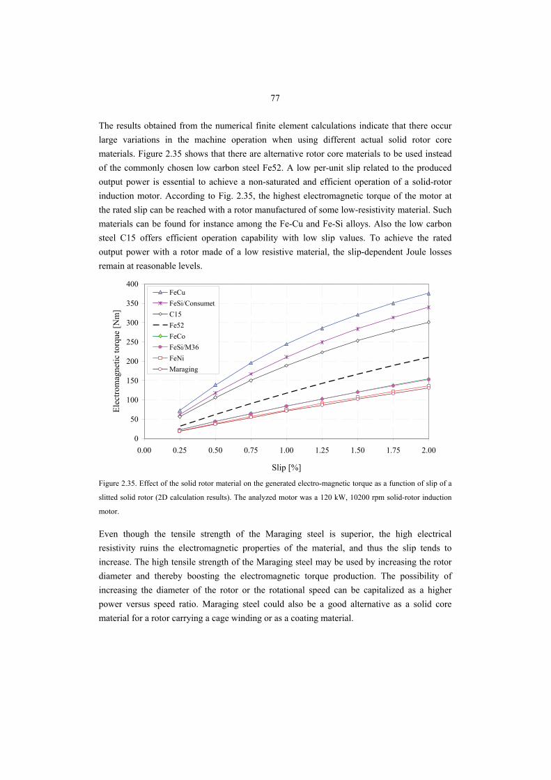
77
The results obtained from the numerical finite element calculations indicate that there occur large variations in the machine operation when using different actual solid rotor core materials. Figure 2.35 shows that there are alternative rotor core materials to be used instead of the commonly chosen low carbon steel Fe52. A low per-unit slip related to the produced output power is essential to achieve a non-saturated and efficient operation of a solid-rotor induction motor. According to Fig. 2.35, the highest electromagnetic torque of the motor at the rated slip can be reached with a rotor manufactured of some low-resistivity material. Such materials can be found for instance among the Fe-Cu and Fe-Si alloys. Also the low carbon steel C15 offers efficient operation capability with low slip values. To achieve the rated output power with a rotor made of a low resistive material, the slip-dependent Joule losses remain at reasonable levels.
0
50
100
150
200
250
300
350
400
0.00 0.25 0.50 0.75 1.00 1.25 1.50 1.75 2.00
Slip [%]
Elec
trom
agne
tic to
rque
[Nm
]
FeCuFeSi/ConsumetC15Fe52FeCoFeSi/M36FeNiMaraging
Figure 2.35. Effect of the solid rotor material on the generated electro-magnetic torque as a function of slip of a
slitted solid rotor (2D calculation results). The analyzed motor was a 120 kW, 10200 rpm solid-rotor induction
motor.
Even though the tensile strength of the Maraging steel is superior, the high electrical resistivity ruins the electromagnetic properties of the material, and thus the slip tends to increase. The high tensile strength of the Maraging steel may be used by increasing the rotor diameter and thereby boosting the electromagnetic torque production. The possibility of increasing the diameter of the rotor or the rotational speed can be capitalized as a higher power versus speed ratio. Maraging steel could also be a good alternative as a solid core material for a rotor carrying a cage winding or as a coating material.
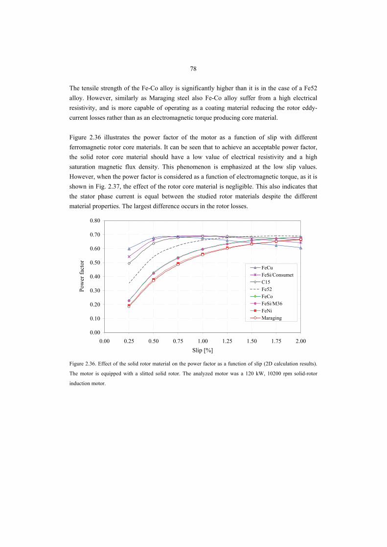
78
The tensile strength of the Fe-Co alloy is significantly higher than it is in the case of a Fe52 alloy. However, similarly as Maraging steel also Fe-Co alloy suffer from a high electrical resistivity, and is more capable of operating as a coating material reducing the rotor eddy-current losses rather than as an electromagnetic torque producing core material. Figure 2.36 illustrates the power factor of the motor as a function of slip with different ferromagnetic rotor core materials. It can be seen that to achieve an acceptable power factor, the solid rotor core material should have a low value of electrical resistivity and a high saturation magnetic flux density. This phenomenon is emphasized at the low slip values. However, when the power factor is considered as a function of electromagnetic torque, as it is shown in Fig. 2.37, the effect of the rotor core material is negligible. This also indicates that the stator phase current is equal between the studied rotor materials despite the different material properties. The largest difference occurs in the rotor losses.
0.00
0.10
0.20
0.30
0.40
0.50
0.60
0.70
0.80
0.00 0.25 0.50 0.75 1.00 1.25 1.50 1.75 2.00Slip [%]
Pow
er fa
ctor
FeCuFeSi/ConsumetC15Fe52FeCoFeSi/M36FeNiMaraging
Figure 2.36. Effect of the solid rotor material on the power factor as a function of slip (2D calculation results).
The motor is equipped with a slitted solid rotor. The analyzed motor was a 120 kW, 10200 rpm solid-rotor
induction motor.
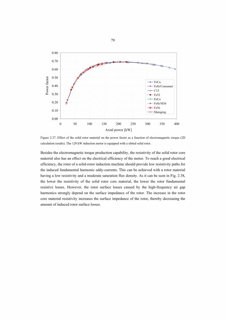
79
0.00
0.10
0.20
0.30
0.40
0.50
0.60
0.70
0.80
0 50 100 150 200 250 300 350 400
Axial power [kW]
Pow
er fa
ctor
FeCuFeSi/ConsumetC15Fe52FeCoFeSi/M36FeNiMaraging
Figure 2.37. Effect of the solid rotor material on the power factor as a function of electromagnetic torque (2D
calculation results). The 120 kW induction motor is equipped with a slitted solid rotor.
Besides the electromagnetic torque production capability, the resistivity of the solid rotor core material also has an effect on the electrical efficiency of the motor. To reach a good electrical efficiency, the rotor of a solid-rotor induction machine should provide low resistivity paths for the induced fundamental harmonic eddy-currents. This can be achieved with a rotor material having a low resistivity and a moderate saturation flux density. As it can be seen in Fig. 2.38, the lower the resistivity of the solid rotor core material, the lower the rotor fundamental resistive losses. However, the rotor surface losses caused by the high-frequency air gap harmonics strongly depend on the surface impedance of the rotor. The increase in the rotor core material resistivity increases the surface impedance of the rotor, thereby decreasing the amount of induced rotor surface losses.
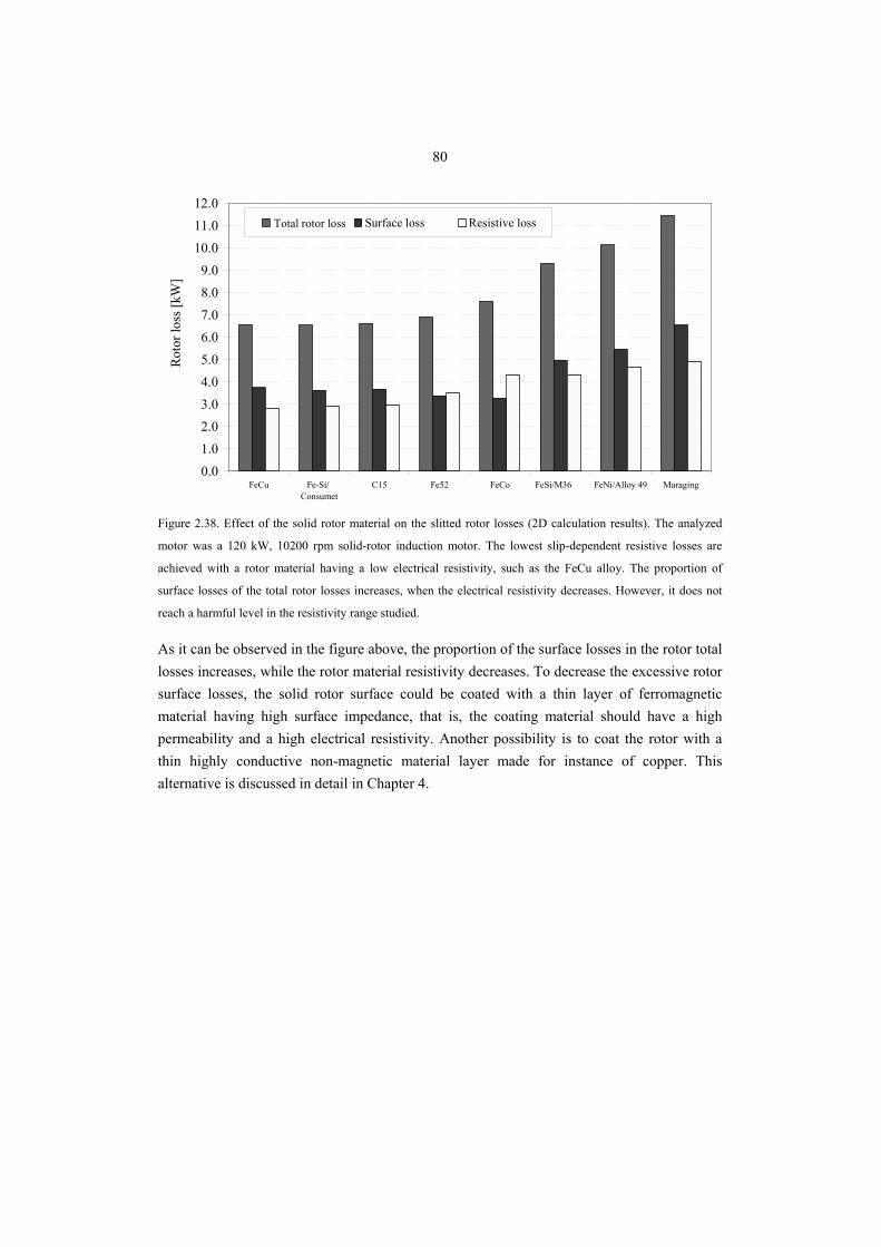
80
0.01.02.03.04.05.06.07.08.09.0
10.011.012.0
FeCu Fe-Si/ Consumet
C15 Fe52 FeCo FeSi/M36 FeNi/Alloy 49 Maraging
Rot
or lo
ss [k
W]
Total loss Surface loss Resistive lossTotal rotor loss
Figure 2.38. Effect of the solid rotor material on the slitted rotor losses (2D calculation results). The analyzed
motor was a 120 kW, 10200 rpm solid-rotor induction motor. The lowest slip-dependent resistive losses are
achieved with a rotor material having a low electrical resistivity, such as the FeCu alloy. The proportion of
surface losses of the total rotor losses increases, when the electrical resistivity decreases. However, it does not
reach a harmful level in the resistivity range studied.
As it can be observed in the figure above, the proportion of the surface losses in the rotor total losses increases, while the rotor material resistivity decreases. To decrease the excessive rotor surface losses, the solid rotor surface could be coated with a thin layer of ferromagnetic material having high surface impedance, that is, the coating material should have a high permeability and a high electrical resistivity. Another possibility is to coat the rotor with a thin highly conductive non-magnetic material layer made for instance of copper. This alternative is discussed in detail in Chapter 4.
81
2.3 Conclusion
In this chapter, the effects of the saturation flux density, initial relative permeability and the electrical resistivity on the performance of the medium-speed solid rotor were comprehensively analyzed. The optimization of the solid rotor material is, however, a very complicated process; the main guidelines may be found in the text above, but are included here for the convenience of the reader:
• The most important torque-production-related factor is the resistivity of the material. The lower the resistivity, the higher the torque at a small slip. This is essential from the efficiency point of view. A low resistivity causes a low surface impedance, and the rotor surface losses caused by the air gap harmonics may be increased. The surface losses do not reach harmful levels in the resistivity range of ferromagnetic alloys. If the resistivity is very low as it would be in the case of surface copper, the surface losses will decrease.
• The saturation flux density is not an essential factor in the torque production. As a compromise for slitted rotor behaviour, the saturation should be fairly high, Bs >1.25 T. For a smooth solid rotor, the saturation should be lower, approximately Bs ≈ 1 T. From the rotor surface losses point of view, the higher saturation flux density values are preferred.
• The initial permeability is not an important factor. We may conclude that the suitable range for slitted solid rotor starts at about the relative initial permeability of 250. If a smooth rotor is made of a material having a high saturation flux density (Bs ≈ 2 T), a low value for the initial relative permeability (μr ≈ 250) is preferred. It is also noteworthy that the surface impedance increases when the relative permeability of the material is increased and the rotor surface losses caused by the air gap harmonics can thus be reduced.
82
3. AXIAL SLITTING OF A SOLID STEEL ROTOR
The simplest and the most traditional solid rotor construction is a smooth steel cylinder. Such a rotor was illustrated in Fig. 1.6. This kind of a rotor is easy to manufacture, and it has the best mechanical and fluid-dynamical properties; however, it is shown by several authors, for instance by Pyrhönen (1996), Bumby (2006) that the electrical performance of a smooth solid-rotor induction motor is often unsatisfactory. The smooth solid iron rotor is characterized by a large apparent resistance and a low magnetization inductance. The electrical performance of a motor with such a rotor is quite poor, as, the slip of the rotor tends to be large and the power factor low. This is mainly because of the low depth of flux penetration in the solid material and the deep saturation of the rotor material. A performance improvement in a solid rotor can be achieved by slitting the cross-section of the rotor in such a way that a better flux penetration into the rotor should be enabled. Slitted solid rotor constructions have been studied for instance by Dorairaj (1967a,b), Jamieson (1968), Rajagopalan (1969), Yamada (1970), Bergmann (1982) and Jinning (1987). Later, a slitted solid-rotor induction motor was analyzed by Zaim (1999) by a FEM program, but only a few rotor slit parameters were used. Also Laporte (1994) investigated optimal rotor slitting, but his studies were not very extensive either. The issue of solid rotor slitting strategies was comprehensively studied by Lähteenmäki (2002) and Huppunen (2004). It is obvious that slitting the rotor decreases the low-frequency impedance of the rotor, thus producing more torque. Slitting also increases the high-frequency surface impedance of the rotor, thus decreasing the rotor eddy-current loss. The drawback of the axial slitting is that the ruggedness of the solid rotor is partly lost. In addition, at very high speeds, the friction between the rotating rotor and air increases remarkably, Eq. (1.23). However, the slitting intensifies the cooling of the rotor owing to the increased cooling surface of the rotor and is thus justified in medium-speed (~10 000 rpm) but maybe not in high-speed applications. A slitted solid rotor construction was illustrated in Fig. 1.6. Although the benefits of rotor slitting are known, relatively little has been published on the effect of the rotor slitting on the performance of the solid-rotor induction motor. Neither the selection of proper rotor slit number has been a topic of discussion in research reports. The effect of the number of rotor slits on the torque of the solid-rotor induction motor was numerically studied by Huppunen (2004); the number of the rotor slits was varied between 28 and 52 while the number of the stator slots was 48 in all the calculations. The study showed that the output torque of the motor as a function of the number of rotor slits has a form of a
83
downwards-opening parabola, the maximum value of which is achieved when the number of the rotor slits lies between 34 and 42, sliding to a higher number when the slip is increased. However, the study was limited only to even numbers of the rotor slits. This was mainly because the use of odd numbers of rotor slits is not allowed in most of the recommendations for slit numbers presented in textbooks (e.g. Richter 1954) on the construction and operation of electrical machines. The effect of an odd number of rotor slots on the motor performance characteristics in the case of a four-pole 15 kW squirrel-cage induction motor was studied by Arkkio (1995); the study showed that the magnitude of the unbalanced magnetic pull caused by the odd numbers of the rotor slots may be large. It was also shown that an odd number of rotor slots might be a good choice when the synchronous torques and rotor losses are considered. Simulations done for the two-pole and four-pole motor showed that the unbalanced forces due to the odd number of rotor slots can be larger than the weight of the rotor. The unbalanced magnetic pull in cage induction motors with eccentric rotors have been studied extensively for instance by Dorrell (1993) and Tenhunen (2003). Among others, Belmans (1991), Kobayashi (1997), Nau (2000) and Maliti (2000) have studied the effects of slot combinations of a squirrel-cage motor on acoustic noise. The effects of different slot combinations are mainly analyzed by both analytical and FEM-based methods. Kim (1999) has studied the optimal slot number of the rotor to reduce the specific harmonics. According to Jinning (1987), the optimal number of slits is between 5 and 15 per pole pair. It was also stated that the optimal depth of a slit equals approximately the magnetic flux penetration depth. In the US patent 5,473,211 (1995) related to high-speed solid-rotor machines, it was claimed that the rotor slit number should be higher than the stator slot number. It was also suggested that the rotor slit number should be larger than the rotor outer diameter in millimetres divided by 3.2. This advice results in a considerably high rotor slit number in a medium-speed solid-rotor machine. In this chapter, the effects of the rotor slit depth and rotor slit number on the torque and power factor of a solid-rotor motor are numerically analyzed. In addition, the effect of the rotor slit number on the torque ripple and the rotor losses are analyzed. The influence of the asymmetric rotor construction on the unbalanced magnetic pull of a medium-speed, high-power solid-rotor induction motor is included in this chapter.
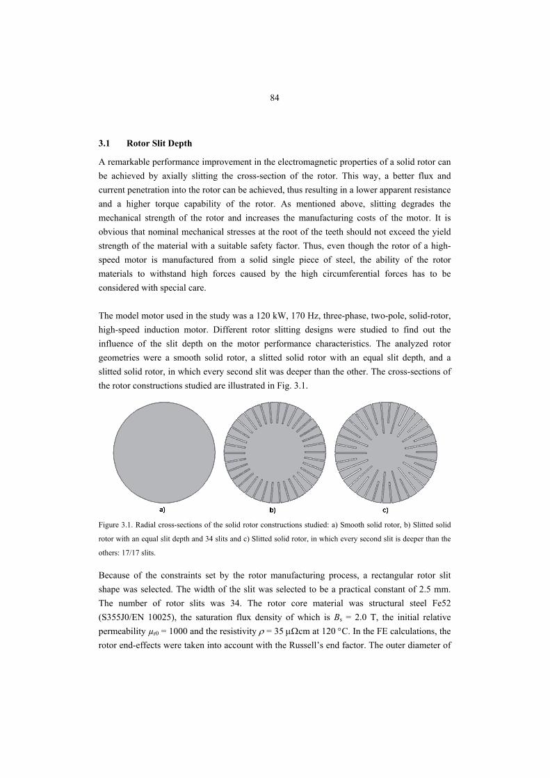
84
3.1 Rotor Slit Depth
A remarkable performance improvement in the electromagnetic properties of a solid rotor can be achieved by axially slitting the cross-section of the rotor. This way, a better flux and current penetration into the rotor can be achieved, thus resulting in a lower apparent resistance and a higher torque capability of the rotor. As mentioned above, slitting degrades the mechanical strength of the rotor and increases the manufacturing costs of the motor. It is obvious that nominal mechanical stresses at the root of the teeth should not exceed the yield strength of the material with a suitable safety factor. Thus, even though the rotor of a high-speed motor is manufactured from a solid single piece of steel, the ability of the rotor materials to withstand high forces caused by the high circumferential forces has to be considered with special care. The model motor used in the study was a 120 kW, 170 Hz, three-phase, two-pole, solid-rotor, high-speed induction motor. Different rotor slitting designs were studied to find out the influence of the slit depth on the motor performance characteristics. The analyzed rotor geometries were a smooth solid rotor, a slitted solid rotor with an equal slit depth, and a slitted solid rotor, in which every second slit was deeper than the other. The cross-sections of the rotor constructions studied are illustrated in Fig. 3.1.
Figure 3.1. Radial cross-sections of the solid rotor constructions studied: a) Smooth solid rotor, b) Slitted solid
rotor with an equal slit depth and 34 slits and c) Slitted solid rotor, in which every second slit is deeper than the
others: 17/17 slits.
Because of the constraints set by the rotor manufacturing process, a rectangular rotor slit shape was selected. The width of the slit was selected to be a practical constant of 2.5 mm. The number of rotor slits was 34. The rotor core material was structural steel Fe52 (S355J0/EN 10025), the saturation flux density of which is Bs = 2.0 T, the initial relative permeability µr0 = 1000 and the resistivity ρ = 35 μΩcm at 120 °C. In the FE calculations, the rotor end-effects were taken into account with the Russell’s end factor. The outer diameter of
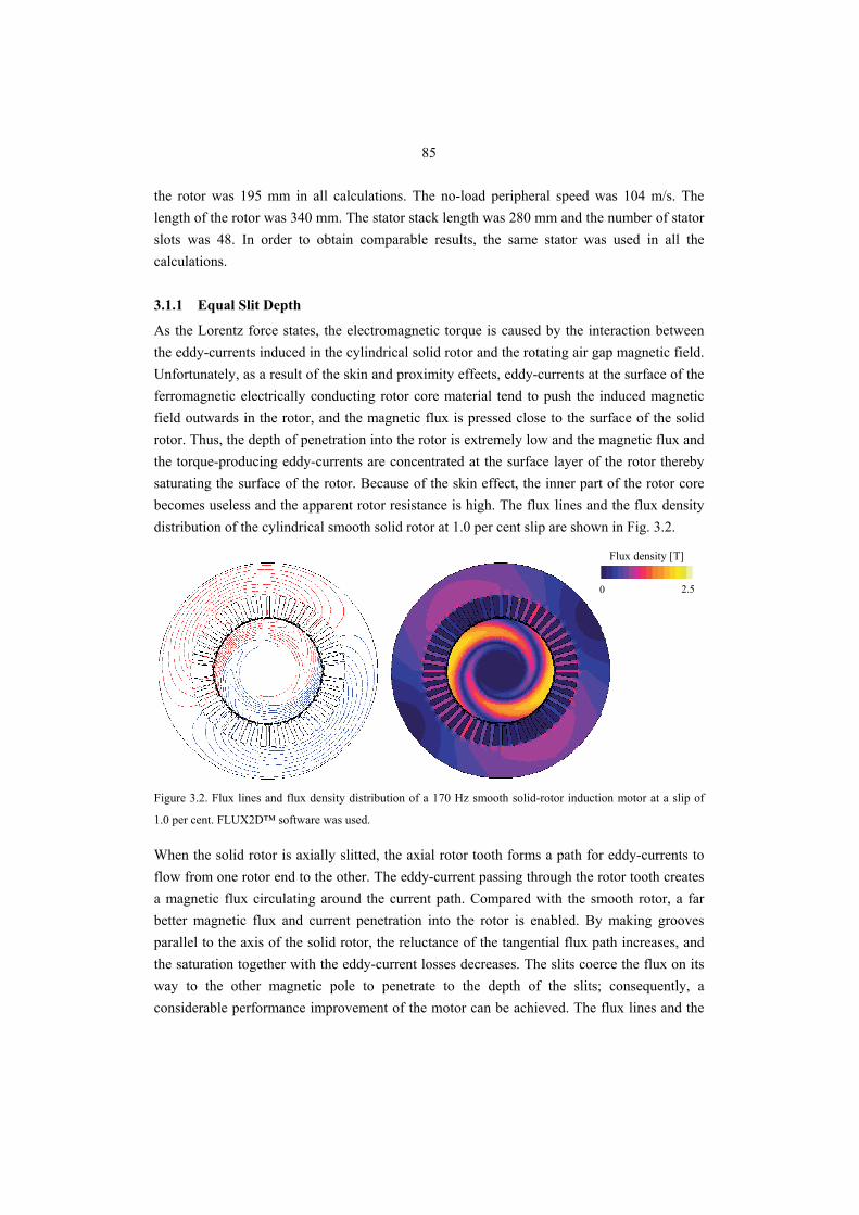
85
the rotor was 195 mm in all calculations. The no-load peripheral speed was 104 m/s. The length of the rotor was 340 mm. The stator stack length was 280 mm and the number of stator slots was 48. In order to obtain comparable results, the same stator was used in all the calculations.
3.1.1 Equal Slit Depth
As the Lorentz force states, the electromagnetic torque is caused by the interaction between the eddy-currents induced in the cylindrical solid rotor and the rotating air gap magnetic field. Unfortunately, as a result of the skin and proximity effects, eddy-currents at the surface of the ferromagnetic electrically conducting rotor core material tend to push the induced magnetic field outwards in the rotor, and the magnetic flux is pressed close to the surface of the solid rotor. Thus, the depth of penetration into the rotor is extremely low and the magnetic flux and the torque-producing eddy-currents are concentrated at the surface layer of the rotor thereby saturating the surface of the rotor. Because of the skin effect, the inner part of the rotor core becomes useless and the apparent rotor resistance is high. The flux lines and the flux density distribution of the cylindrical smooth solid rotor at 1.0 per cent slip are shown in Fig. 3.2.
0 2.5
Flux density [T]
Figure 3.2. Flux lines and flux density distribution of a 170 Hz smooth solid-rotor induction motor at a slip of
1.0 per cent. FLUX2D™ software was used.
When the solid rotor is axially slitted, the axial rotor tooth forms a path for eddy-currents to flow from one rotor end to the other. The eddy-current passing through the rotor tooth creates a magnetic flux circulating around the current path. Compared with the smooth rotor, a far better magnetic flux and current penetration into the rotor is enabled. By making grooves parallel to the axis of the solid rotor, the reluctance of the tangential flux path increases, and the saturation together with the eddy-current losses decreases. The slits coerce the flux on its way to the other magnetic pole to penetrate to the depth of the slits; consequently, a considerable performance improvement of the motor can be achieved. The flux lines and the
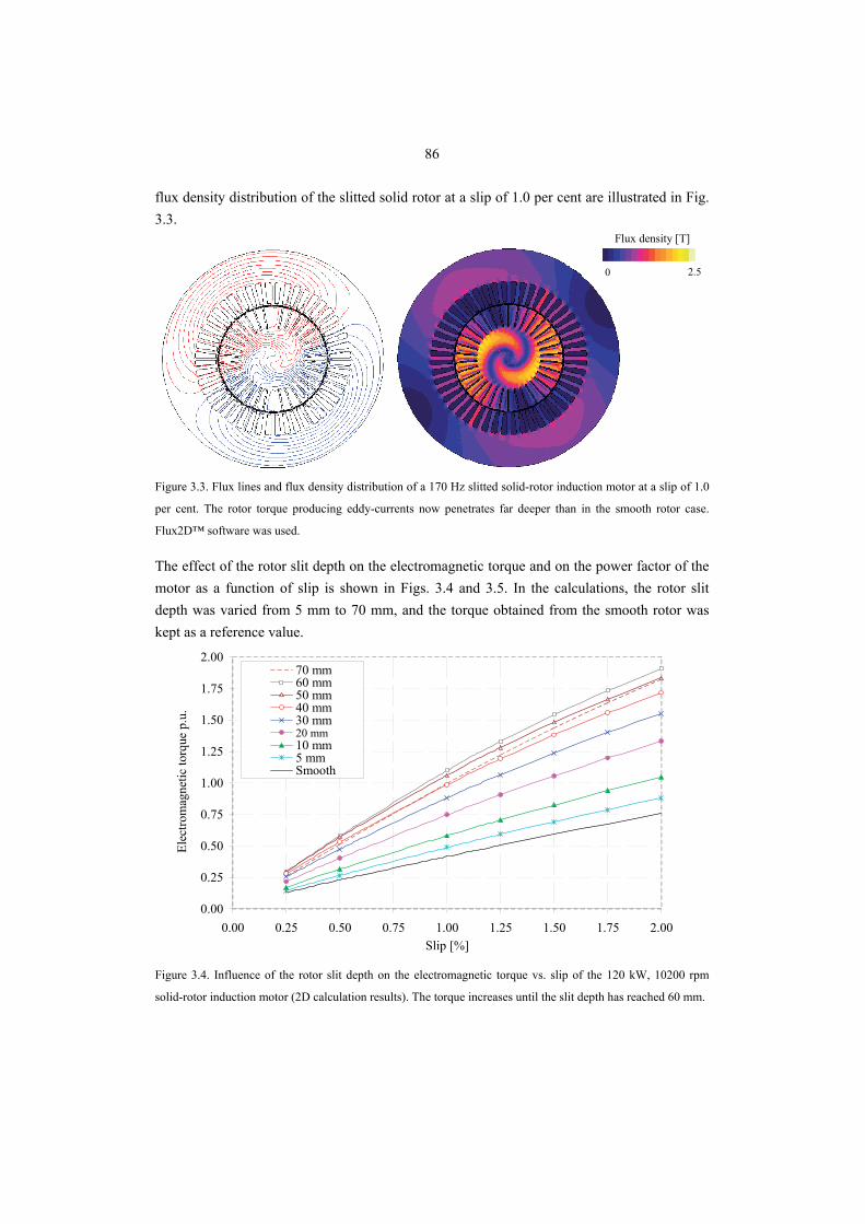
86
flux density distribution of the slitted solid rotor at a slip of 1.0 per cent are illustrated in Fig. 3.3.
0 2.5
Flux density [T]
Figure 3.3. Flux lines and flux density distribution of a 170 Hz slitted solid-rotor induction motor at a slip of 1.0
per cent. The rotor torque producing eddy-currents now penetrates far deeper than in the smooth rotor case.
Flux2D™ software was used.
The effect of the rotor slit depth on the electromagnetic torque and on the power factor of the motor as a function of slip is shown in Figs. 3.4 and 3.5. In the calculations, the rotor slit depth was varied from 5 mm to 70 mm, and the torque obtained from the smooth rotor was kept as a reference value.
0.00
0.25
0.50
0.75
1.00
1.25
1.50
1.75
2.00
0.00 0.25 0.50 0.75 1.00 1.25 1.50 1.75 2.00Slip [%]
Elec
trom
agne
tic to
rque
p.u
.
70 mm60 mm50 mm40 mm30 mm20 mm10 mm5 mmSmooth
Figure 3.4. Influence of the rotor slit depth on the electromagnetic torque vs. slip of the 120 kW, 10200 rpm
solid-rotor induction motor (2D calculation results). The torque increases until the slit depth has reached 60 mm.
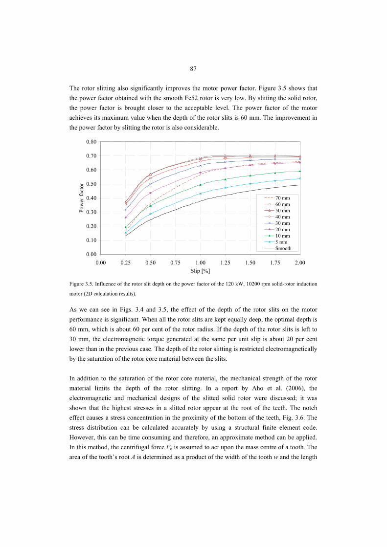
87
The rotor slitting also significantly improves the motor power factor. Figure 3.5 shows that the power factor obtained with the smooth Fe52 rotor is very low. By slitting the solid rotor, the power factor is brought closer to the acceptable level. The power factor of the motor achieves its maximum value when the depth of the rotor slits is 60 mm. The improvement in the power factor by slitting the rotor is also considerable.
0.00
0.10
0.20
0.30
0.40
0.50
0.60
0.70
0.80
0.00 0.25 0.50 0.75 1.00 1.25 1.50 1.75 2.00Slip [%]
Pow
er fa
ctor
70 mm60 mm50 mm40 mm30 mm20 mm10 mm5 mmSmooth
Figure 3.5. Influence of the rotor slit depth on the power factor of the 120 kW, 10200 rpm solid-rotor induction
motor (2D calculation results).
As we can see in Figs. 3.4 and 3.5, the effect of the depth of the rotor slits on the motor performance is significant. When all the rotor slits are kept equally deep, the optimal depth is 60 mm, which is about 60 per cent of the rotor radius. If the depth of the rotor slits is left to 30 mm, the electromagnetic torque generated at the same per unit slip is about 20 per cent lower than in the previous case. The depth of the rotor slitting is restricted electromagnetically by the saturation of the rotor core material between the slits. In addition to the saturation of the rotor core material, the mechanical strength of the rotor material limits the depth of the rotor slitting. In a report by Aho et al. (2006), the electromagnetic and mechanical designs of the slitted solid rotor were discussed; it was shown that the highest stresses in a slitted rotor appear at the root of the teeth. The notch effect causes a stress concentration in the proximity of the bottom of the teeth, Fig. 3.6. The stress distribution can be calculated accurately by using a structural finite element code. However, this can be time consuming and therefore, an approximate method can be applied. In this method, the centrifugal force Fc is assumed to act upon the mass centre of a tooth. The area of the tooth’s root A is determined as a product of the width of the tooth w and the length
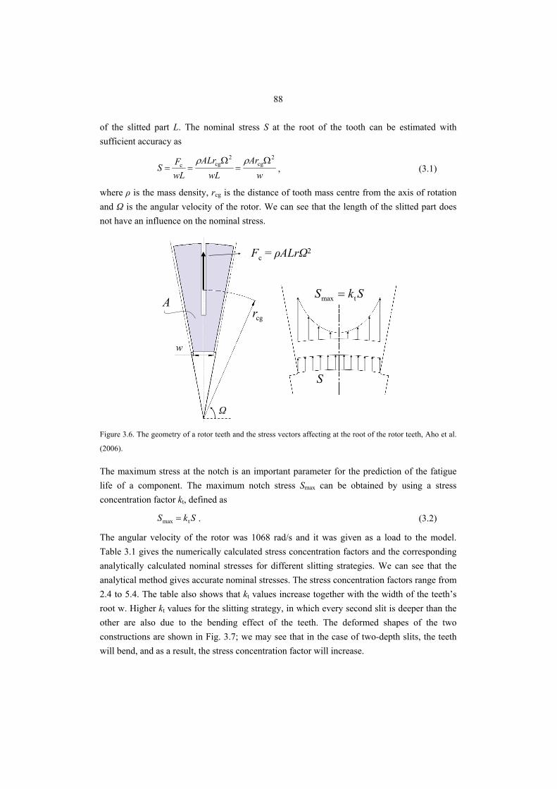
88
of the slitted part L. The nominal stress S at the root of the tooth can be estimated with sufficient accuracy as
wAr
wLALr
wLFS
2cg
2cgc Ω
=Ω
==ρρ
, (3.1)
where ρ is the mass density, rcg is the distance of tooth mass centre from the axis of rotation and Ω is the angular velocity of the rotor. We can see that the length of the slitted part does not have an influence on the nominal stress.
cgrA
s
2c cgF ALrρ ω=
max tS k S=
S
ω
w
Ω
Fc = ρALrΩ2
Figure 3.6. The geometry of a rotor teeth and the stress vectors affecting at the root of the rotor teeth, Aho et al.
(2006).
The maximum stress at the notch is an important parameter for the prediction of the fatigue life of a component. The maximum notch stress Smax can be obtained by using a stress concentration factor kt, defined as
SkS tmax = . (3.2)
The angular velocity of the rotor was 1068 rad/s and it was given as a load to the model. Table 3.1 gives the numerically calculated stress concentration factors and the corresponding analytically calculated nominal stresses for different slitting strategies. We can see that the analytical method gives accurate nominal stresses. The stress concentration factors range from 2.4 to 5.4. The table also shows that kt values increase together with the width of the teeth’s root w. Higher kt values for the slitting strategy, in which every second slit is deeper than the other are also due to the bending effect of the teeth. The deformed shapes of the two constructions are shown in Fig. 3.7; we may see that in the case of two-depth slits, the teeth will bend, and as a result, the stress concentration factor will increase.
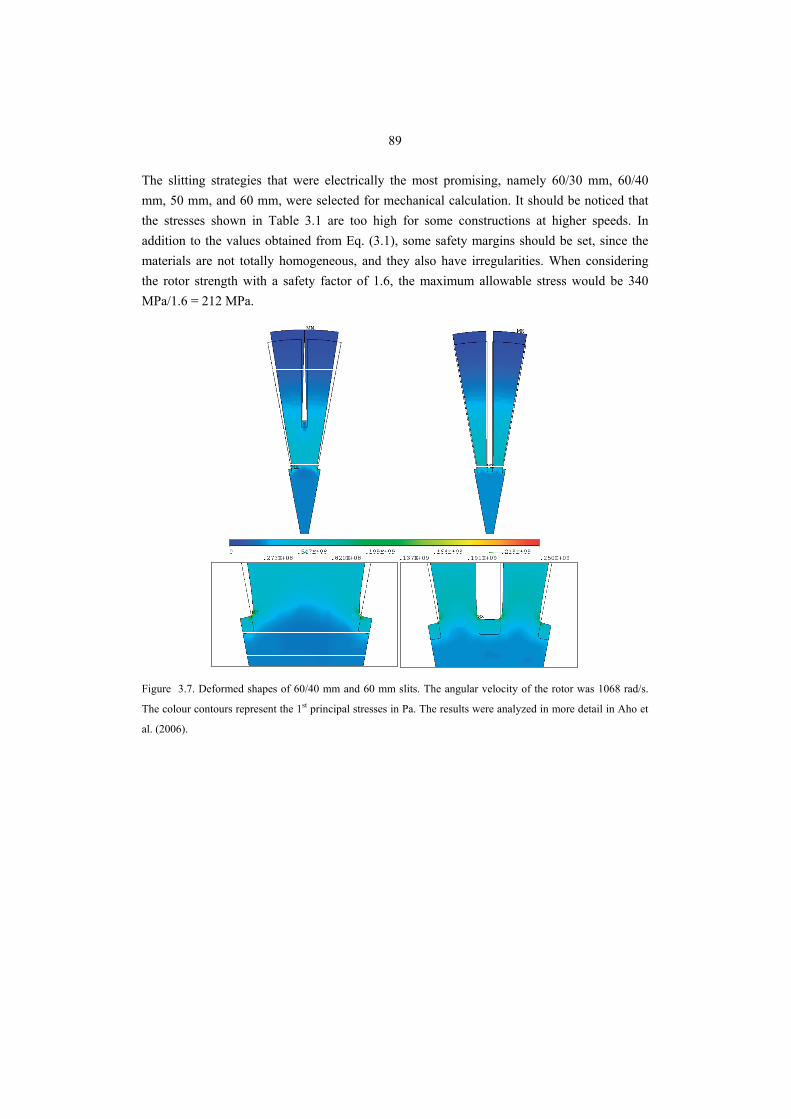
89
The slitting strategies that were electrically the most promising, namely 60/30 mm, 60/40 mm, 50 mm, and 60 mm, were selected for mechanical calculation. It should be noticed that the stresses shown in Table 3.1 are too high for some constructions at higher speeds. In addition to the values obtained from Eq. (3.1), some safety margins should be set, since the materials are not totally homogeneous, and they also have irregularities. When considering the rotor strength with a safety factor of 1.6, the maximum allowable stress would be 340 MPa/1.6 = 212 MPa.
Figure 3.7. Deformed shapes of 60/40 mm and 60 mm slits. The angular velocity of the rotor was 1068 rad/s.
The colour contours represent the 1st principal stresses in Pa. The results were analyzed in more detail in Aho et
al. (2006).
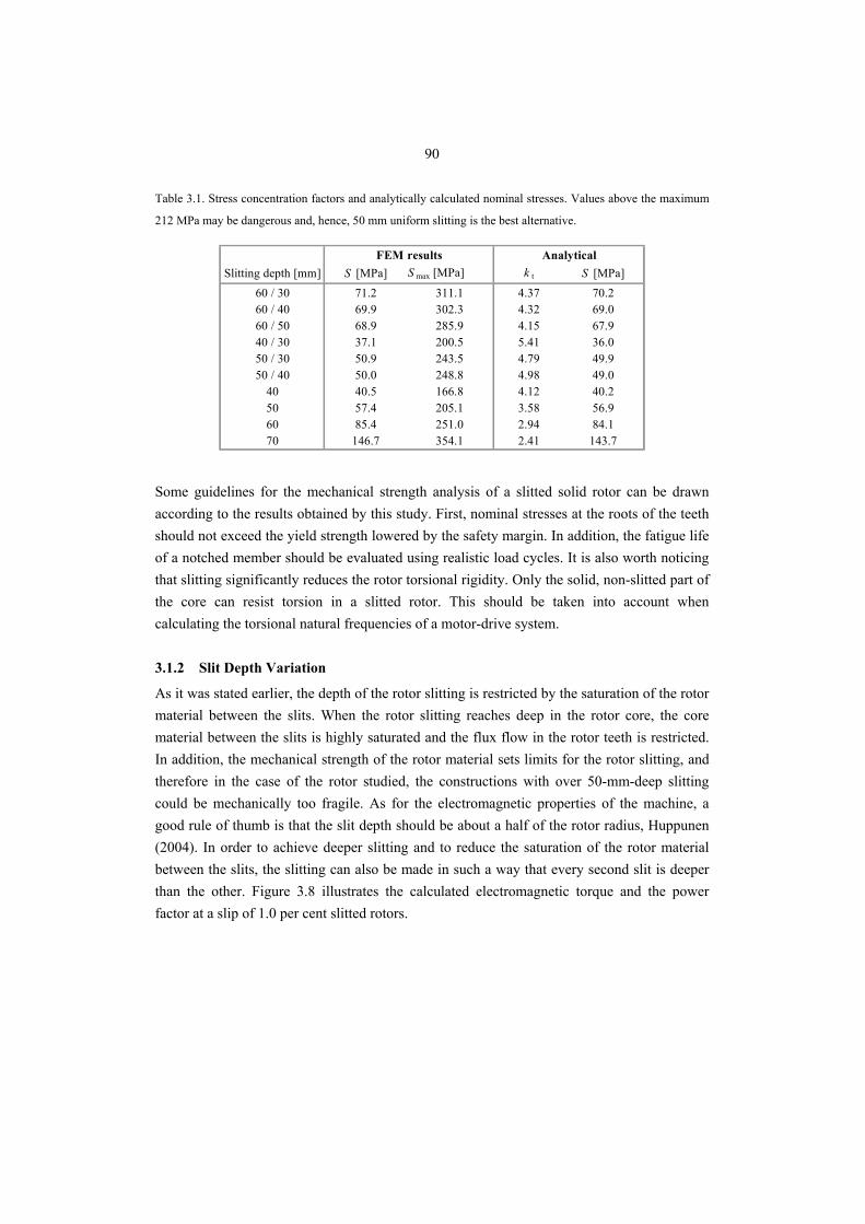
90
Table 3.1. Stress concentration factors and analytically calculated nominal stresses. Values above the maximum
212 MPa may be dangerous and, hence, 50 mm uniform slitting is the best alternative.
Slitting depth [mm] S [MPa] S max [MPa] k t S [MPa]60 / 30 71.2 311.1 4.37 70.260 / 40 69.9 302.3 4.32 69.060 / 50 68.9 285.9 4.15 67.940 / 30 37.1 200.5 5.41 36.050 / 30 50.9 243.5 4.79 49.950 / 40 50.0 248.8 4.98 49.0
40 40.5 166.8 4.12 40.250 57.4 205.1 3.58 56.960 85.4 251.0 2.94 84.170 146.7 354.1 2.41 143.7
FEM results Analytical
Some guidelines for the mechanical strength analysis of a slitted solid rotor can be drawn according to the results obtained by this study. First, nominal stresses at the roots of the teeth should not exceed the yield strength lowered by the safety margin. In addition, the fatigue life of a notched member should be evaluated using realistic load cycles. It is also worth noticing that slitting significantly reduces the rotor torsional rigidity. Only the solid, non-slitted part of the core can resist torsion in a slitted rotor. This should be taken into account when calculating the torsional natural frequencies of a motor-drive system.
3.1.2 Slit Depth Variation
As it was stated earlier, the depth of the rotor slitting is restricted by the saturation of the rotor material between the slits. When the rotor slitting reaches deep in the rotor core, the core material between the slits is highly saturated and the flux flow in the rotor teeth is restricted. In addition, the mechanical strength of the rotor material sets limits for the rotor slitting, and therefore in the case of the rotor studied, the constructions with over 50-mm-deep slitting could be mechanically too fragile. As for the electromagnetic properties of the machine, a good rule of thumb is that the slit depth should be about a half of the rotor radius, Huppunen (2004). In order to achieve deeper slitting and to reduce the saturation of the rotor material between the slits, the slitting can also be made in such a way that every second slit is deeper than the other. Figure 3.8 illustrates the calculated electromagnetic torque and the power factor at a slip of 1.0 per cent slitted rotors.
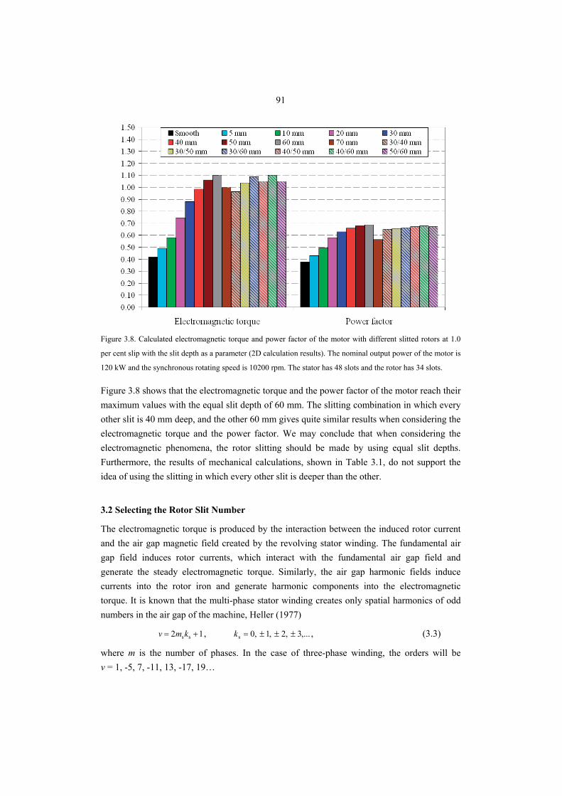
91
Figure 3.8. Calculated electromagnetic torque and power factor of the motor with different slitted rotors at 1.0
per cent slip with the slit depth as a parameter (2D calculation results). The nominal output power of the motor is
120 kW and the synchronous rotating speed is 10200 rpm. The stator has 48 slots and the rotor has 34 slots.
Figure 3.8 shows that the electromagnetic torque and the power factor of the motor reach their maximum values with the equal slit depth of 60 mm. The slitting combination in which every other slit is 40 mm deep, and the other 60 mm gives quite similar results when considering the electromagnetic torque and the power factor. We may conclude that when considering the electromagnetic phenomena, the rotor slitting should be made by using equal slit depths. Furthermore, the results of mechanical calculations, shown in Table 3.1, do not support the idea of using the slitting in which every other slit is deeper than the other.
3.2 Selecting the Rotor Slit Number
The electromagnetic torque is produced by the interaction between the induced rotor current and the air gap magnetic field created by the revolving stator winding. The fundamental air gap field induces rotor currents, which interact with the fundamental air gap field and generate the steady electromagnetic torque. Similarly, the air gap harmonic fields induce currents into the rotor iron and generate harmonic components into the electromagnetic torque. It is known that the multi-phase stator winding creates only spatial harmonics of odd numbers in the air gap of the machine, Heller (1977)
12 ss += kmv , ,...3,2,1,0s ±±±=k , (3.3)
where m is the number of phases. In the case of three-phase winding, the orders will be v = 1, -5, 7, -11, 13, -17, 19…
92
Stator slotting causes permeance harmonics, the orders of which are
slots
slotssslot 121 kp
Qkqmv +=+= , ,...3,2,1slot ±±±=k (3.4)
where Qs is the number of stator slots and q is the number of slots per pole and per phase. In addition to spatial harmonics caused by the distributed winding system and permeance harmonics, also time harmonics caused by an inverter supply are possible. The electric angular frequency of the rotating air gap magnetic field can be defined as
vvωω = . (3.5)
The air gap magnetic field induces a current in the rotor iron. The angular frequency of the rotor current ωrv reflects from the air gap magnetic field
( ) vv ssv
v ωωωω =⎥⎦⎤
⎢⎣⎡ −−= 1r . (3.6)
The currents induced in the rotor iron create their own air gap magnetic fields having orders
rr k
pQv +=μ , ,...3,2,1,0r ±±±=k (3.7)
where Qr is the number of rotor slits. Following the basic principles for the rotor and stator air gap fields, the following interactions can be derived:
• The fundamental fields with v = 1 and μ = 1 generate asynchronous torque and form the basis for the operation of an induction machine.
• The rotor harmonic magnetic field μ = v induced by the stator harmonic fields (v ≠ 1) generates harmonic asynchronous air gap torque components.
• The rotor harmonic magnetic fields μ ≠ v induced by stator fundamental wave (v = 1) may interact with stator harmonic fields and generate synchronous air gap torques.
• The rotor harmonic magnetic fields μ ≠ v created by stator harmonics (v ≠ 1) may generate synchronous air gap torques.
In the following, interactions with different stator-rotor slot combinations are studied. In principle, the phenomena observed can be explained based on the above list. To reduce the frequency-dependent losses and to obtain acceptable power factors, the high-speed machines normally have a two-pole winding. In three-phase machines, the -5th and 7th -order air gap harmonic components tend to generate the 6th -order harmonic current on the rotor side. This causes pulsating electromagnetic torque, which has the frequency of six times the supply frequency. The induction of the 6th -order rotor current harmonic can be reduced with a 5/6 short pitch winding on the stator side. For a 5/6 short pitch winding, the number of stator slots
93
has to be evenly divisible with 2pm. Therefore, the possible numbers of the stator slots for a two-pole motor are 12, 24, 36, 48, 60, etc. In the following study, the selection of the rotor slit number in the case of a motor with 48 stator slots is discussed. In the study, the rotor dimensions were kept as constants. In the study, the rotor dimensions were kept constant: however, the rotor slit number was varied between 28 and 39.
3.2.1 Stator – Rotor Slot Combinations
The effect of the air gap harmonic fields on the vibration of electromagnetic torque depends highly on the ratio of the slot numbers of the stator and the rotor. In order to avoid the disturbance caused by asynchronous and synchronous torques and vibration in the operation of an induction motor, the rotor slit number Qr with respect to the stator slot number has to be selected properly. The following conditions, shown in Eqs. (3.8)–(3.16), are based on the work presented by Richter (1954). To reduce the asynchronous harmonic torque, the rotor slit number has to be as small as possible. It is generally recommended that
sr 25.1 QQ < , (3.8)
where Qs is the number of the stator slots. Therefore, in the case of 48 stator slots, the number of rotor slits should be smaller than 60. A three-phase winding creates only harmonics of odd numbers. To limit the synchronous torques when the motor is at stall, the slit number of the rotor has to meet the condition
,6r pgQ ≠ (3.9)
where p is the number of pole pairs and g may be any positive integer. Equation (3.9) shows that in the studied range of rotor slits, the rotor slit numbers 30 and 36 are not recommended. However, in the speed-controlled electrical drives, the supply frequency of the motor is gradually increased. Thus, the situation where the rotor is at stall and the stator frequency has its nominal value cannot exist. To avoid synchronous torques created by slot harmonics, the selection of the rotor slit number has to meet the following conditions
srsrsr 2 ; 21 ; QQQQQQ ≠≠≠ . (3.10)
All of the studied rotor slit numbers meet the conditions of (3.10).
94
To avoid harmful synchronous torques during running, the following inequality has to be valid
ppgQ 26r ±≠ , (3.11)
where g is again any positive integer. The + sign is valid for positive rotation speeds and - sign for negative rotation speeds. We see in Eq. (3.11) that the rotor slit numbers 32 and 38 would create synchronous torques at positive rotation speeds, while the rotor slit numbers 28 and 34 would create synchronous torques at negative rotation speeds. To avoid dangerous slot harmonics, the following inequalities have to be valid
pQQpQQ 22 ; 2 srsr ±≠±≠ , (3.12)
pQQpQQ ±≠±≠2
; srsr . (3.13)
We see that none of the studied rotor slit numbers meets the conditions of (3.12) or (3.13). In order to avoid mechanical vibrations, the following inequalities have to be valid
16r ±≠ pgQ (3.14)
126r ±±≠ ppgQ (3.15)
126r mppgQ ±≠ . (3.16)
As it is seen in Eqs. (3.14)–(3.16), all odd rotor slit numbers should cause mechanical vibrations. This can be explained as follows. When the number of rotor slits is an even number, the large local normal forces between the stator teeth and the rotor teeth cancel each other on the perimeter on the air gap, and the net force acting on the rotor is zero. If the number of rotor slits is an odd number, the motor geometry is not symmetric enough to eliminate the forces, and a net force, known as unbalanced magnetic pull, usually occurs. However, the estimation of the magnitude of the unbalanced magnetic pull caused by the odd number of rotor slits is very difficult, and therefore odd numbers of rotor slits are very rarely approached in the machine design.
3.2.2 Effect on the Motor Performance
In the following, the selection of the rotor slit number in the case of a two-pole motor with 48 stator slots is discussed. The solid rotor was axially slitted and six different odd rotor slit numbers, 29, 31, 33, 35, 37 and 39 were analyzed. In order to compare the effect of the odd number of the rotor slits on the performance of the motor, the calculations were also performed with six different even rotor slit numbers, viz. 28, 30, 32, 34, 36 and 38. In all calculations, the shape of the rotor slit was selected to be rectangular. The depth of a slit was
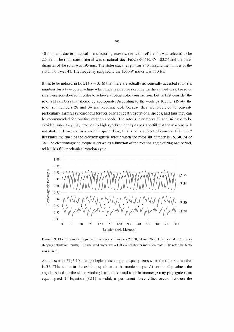
95
40 mm, and due to practical manufacturing reasons, the width of the slit was selected to be 2.5 mm. The rotor core material was structural steel Fe52 (S355J0/EN 10025) and the outer diameter of the rotor was 195 mm. The stator stack length was 340 mm and the number of the stator slots was 48. The frequency supplied to the 120 kW motor was 170 Hz. It has to be noticed in Eqs. (3.8)–(3.16) that there are actually no generally accepted rotor slit numbers for a two-pole machine when there is no rotor skewing. In the studied case, the rotor slits were non-skewed in order to achieve a robust rotor construction. Let us first consider the rotor slit numbers that should be appropriate. According to the work by Richter (1954), the rotor slit numbers 28 and 34 are recommended, because they are predicted to generate particularly harmful synchronous torques only at negative rotational speeds, and thus they can be recommended for positive rotation speeds. The rotor slit numbers 30 and 36 have to be avoided, since they may produce so high synchronic torques at standstill that the machine will not start up. However, in a variable speed drive, this is not a subject of concern. Figure 3.9 illustrates the trace of the electromagnetic torque when the rotor slit number is 28, 30, 34 or 36. The electromagnetic torque is drawn as a function of the rotation angle during one period, which is a full mechanical rotation cycle.
0.91
0.92
0.93
0.94
0.95
0.96
0.97
0.98
0.99
1.00
0 30 60 90 120 150 180 210 240 270 300 330 360
Rotation angle [degrees]
Elec
trom
agne
tic to
rque
p.u
.
Qr 28
Qr 34
Qr 30
Qr 36
Figure 3.9. Electromagnetic torque with the rotor slit numbers 28, 30, 34 and 36 at 1 per cent slip (2D time-
stepping calculation results). The analyzed motor was a 120 kW solid-rotor induction motor. The rotor slit depth
was 40 mm.
As it is seen in Fig 3.10, a large ripple in the air gap torque appears when the rotor slit number is 32. This is due to the existing synchronous harmonic torque. At certain slip values, the angular speed for the stator winding harmonics v and rotor harmonics μ may propagate at an equal speed. If Equation (3.11) is valid, a permanent force effect occurs between the
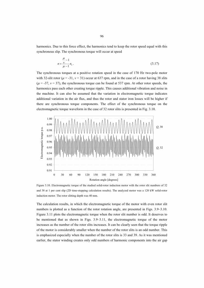
96
harmonics. Due to this force effect, the harmonics tend to keep the rotor speed equal with this synchronous slip. The synchronous torque will occur at speed
s1
1nvn
−
−=
μ
μ
. (3.17)
The synchronous torques at a positive rotation speed in the case of 170 Hz two-pole motor with 32-slit rotor (μ = -31, v = 31) occur at 637 rpm, and in the case of a rotor having 38 slits (μ = -37, v = 37), the synchronous torque can be found at 537 rpm. At other rotor speeds, the harmonics pass each other creating torque ripple. This causes additional vibration and noise in the machine. It can also be assumed that the variation in electromagnetic torque indicates additional variation in the air flux, and thus the rotor and stator iron losses will be higher if there are synchronous torque components. The effect of the synchronous torque on the electromagnetic torque waveform in the case of 32 rotor slits is presented in Fig. 3.10.
0.91
0.92
0.93
0.94
0.95
0.96
0.97
0.98
0.99
1.00
0 30 60 90 120 150 180 210 240 270 300 330 360
Rotation angle [degrees]
Elec
trom
agne
tic to
rque
p.u
.
Qr 32
Qr 38
Figure 3.10. Electromagnetic torque of the studied solid-rotor induction motor with the rotor slit numbers of 32
and 38 at 1 per cent slip (2D time-stepping calculation results). The analyzed motor was a 120 kW solid-rotor
induction motor. The rotor slitting depth was 40 mm.
The calculation results, in which the electromagnetic torque of the motor with even rotor slit numbers is plotted as a function of the rotor rotation angle, are presented in Figs. 3.9–3.10. Figure 3.11 plots the electromagnetic torque when the rotor slit number is odd. It deserves to be mentioned that as shown in Figs. 3.9–3.11, the electromagnetic torque of the motor increases as the number of the rotor slits increases. It can be clearly seen that the torque ripple of the motor is considerably smaller when the number of the rotor slits is an odd number. This is emphasized especially when the number of the rotor slits is 33 and 39. As it was mentioned earlier, the stator winding creates only odd numbers of harmonic components into the air gap
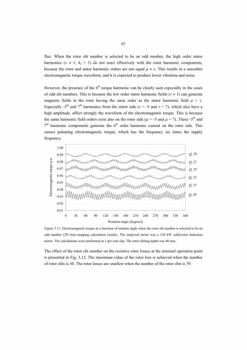
97
flux. When the rotor slit number is selected to be an odd number, the high order stator harmonics (v ≠ 1, ks > 1) do not react effectively with the rotor harmonic components, because the rotor and stator harmonic orders are not equal μ ≠ v. This results in a smoother electromagnetic torque waveform, and it is expected to produce lower vibration and noise. However, the presence of the 6th torque harmonic can be clearly seen especially in the cases of odd slit numbers. This is because the low order stator harmonic fields (v ≠ 1) can generate magnetic fields in the rotor having the same order as the stator harmonic field μ = v. Especially -5th and 7th harmonics from the stator side (v = -5 and v = 7), which also have a high amplitude, affect strongly the waveform of the electromagnetic torque. This is because the same harmonic field orders exist also on the rotor side (μ = -5 and μ = 7). These -5th and 7th harmonic components generate the 6th order harmonic current on the rotor side. This causes pulsating electromagnetic torque, which has the frequency six times the supply frequency.
0.91
0.92
0.93
0.94
0.95
0.96
0.97
0.98
0.99
1.00
0 30 60 90 120 150 180 210 240 270 300 330 360
Rotation angle [degrees]
Elec
trom
agne
tic to
rque
p.u
.
Qr 29
Qr 35
Qr 31
Qr 37
Qr 33
Qr 39
Figure 3.11. Electromagnetic torque as a function of rotation angle when the rotor slit number is selected to be an
odd number (2D time-stepping calculation results). The analyzed motor was a 120 kW solid-rotor induction
motor. The calculations were performed at 1 per cent slip. The rotor slitting depth was 40 mm.
The effect of the rotor slit number on the resistive rotor losses at the nominal operation point is presented in Fig. 3.12. The maximum value of the rotor loss is achieved when the number of rotor slits is 30. The rotor losses are smallest when the number of the rotor slits is 39.
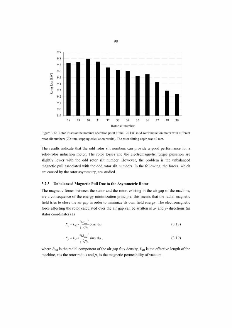
98
8.9
9.0
9.1
9.2
9.3
9.4
9.5
9.6
9.7
9.8
9.9
28 29 30 31 32 33 34 35 36 37 38 39
Rotor slit number
Rot
or lo
ss [k
W]
Figure 3.12. Rotor losses at the nominal operation point of the 120 kW solid-rotor induction motor with different
rotor slit numbers (2D time-stepping calculation results). The rotor slitting depth was 40 mm.
The results indicate that the odd rotor slit numbers can provide a good performance for a solid-rotor induction motor. The rotor losses and the electromagnetic torque pulsation are slightly lower with the odd rotor slit number. However, the problem is the unbalanced magnetic pull associated with the odd rotor slit numbers. In the following, the forces, which are caused by the rotor asymmetry, are studied.
3.2.3 Unbalanced Magnetic Pull Due to the Asymmetric Rotor
The magnetic forces between the stator and the rotor, existing in the air gap of the machine, are a consequence of the energy minimization principle; this means that the radial magnetic field tries to close the air gap in order to minimize its own field energy. The electromagnetic force affecting the rotor calculated over the air gap can be written in x- and y- directions (in stator coordinates) as
ααμ
d cos2
2π
0 0
2rad
effx ∫=BrLF , (3.18)
ααμ
d sin2
2π
0 0
2rad
effy ∫=BrLF , (3.19)
where Brad is the radial component of the air gap flux density, Leff is the effective length of the machine, r is the rotor radius and μ0 is the magnetic permeability of vacuum.
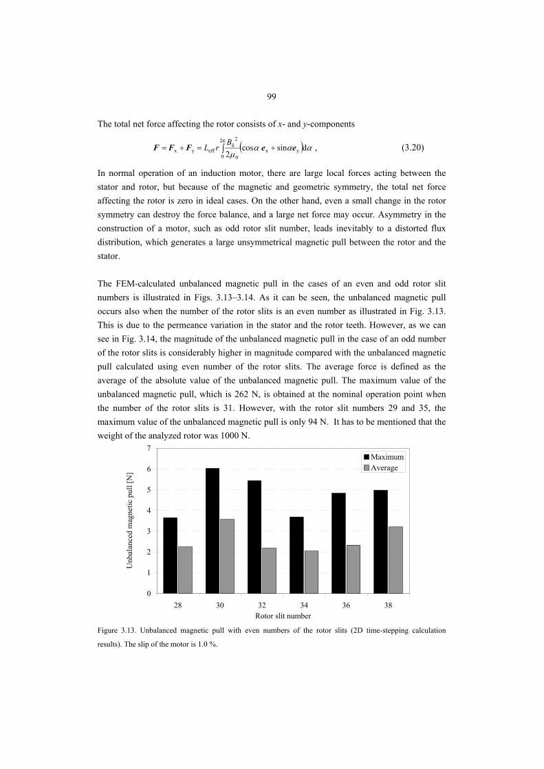
99
The total net force affecting the rotor consists of x- and y-components
( ) αααμ
dsin cos2 yx
2π
0 0
2δ
effyx eeFFF +=+= ∫BrL , (3.20)
In normal operation of an induction motor, there are large local forces acting between the stator and rotor, but because of the magnetic and geometric symmetry, the total net force affecting the rotor is zero in ideal cases. On the other hand, even a small change in the rotor symmetry can destroy the force balance, and a large net force may occur. Asymmetry in the construction of a motor, such as odd rotor slit number, leads inevitably to a distorted flux distribution, which generates a large unsymmetrical magnetic pull between the rotor and the stator. The FEM-calculated unbalanced magnetic pull in the cases of an even and odd rotor slit numbers is illustrated in Figs. 3.13–3.14. As it can be seen, the unbalanced magnetic pull occurs also when the number of the rotor slits is an even number as illustrated in Fig. 3.13. This is due to the permeance variation in the stator and the rotor teeth. However, as we can see in Fig. 3.14, the magnitude of the unbalanced magnetic pull in the case of an odd number of the rotor slits is considerably higher in magnitude compared with the unbalanced magnetic pull calculated using even number of the rotor slits. The average force is defined as the average of the absolute value of the unbalanced magnetic pull. The maximum value of the unbalanced magnetic pull, which is 262 N, is obtained at the nominal operation point when the number of the rotor slits is 31. However, with the rotor slit numbers 29 and 35, the maximum value of the unbalanced magnetic pull is only 94 N. It has to be mentioned that the weight of the analyzed rotor was 1000 N.
0
1
2
3
4
5
6
7
28 30 32 34 36 38Rotor slit number
Unb
alan
ced
mag
netic
pul
l [N
]
MaximumAverage
Figure 3.13. Unbalanced magnetic pull with even numbers of the rotor slits (2D time-stepping calculation
results). The slip of the motor is 1.0 %.
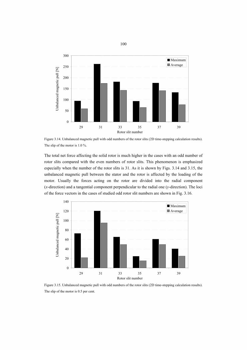
100
0
50
100
150
200
250
300
29 31 33 35 37 39Rotor slit number
Unb
alan
ced
mag
netic
pul
l [N
]MaximumAverage
Figure 3.14. Unbalanced magnetic pull with odd numbers of the rotor slits (2D time-stepping calculation results).
The slip of the motor is 1.0 %.
The total net force affecting the solid rotor is much higher in the cases with an odd number of rotor slits compared with the even numbers of rotor slits. This phenomenon is emphasized especially when the number of the rotor slits is 31. As it is shown by Figs. 3.14 and 3.15, the unbalanced magnetic pull between the stator and the rotor is affected by the loading of the motor. Usually the forces acting on the rotor are divided into the radial component (x-direction) and a tangential component perpendicular to the radial one (y-direction). The loci of the force vectors in the cases of studied odd rotor slit numbers are shown in Fig. 3.16.
0
20
40
60
80
100
120
140
29 31 33 35 37 39Rotor slit number
Unb
alan
ced
mag
netic
pul
l [N
]
MaximumAverage
Figure 3.15. Unbalanced magnetic pull with odd numbers of the rotor slits (2D time-stepping calculation results).
The slip of the motor is 0.5 per cent.
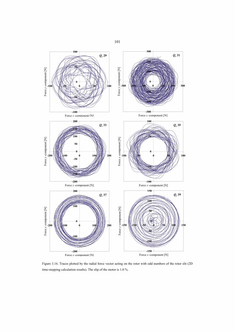
101
-100
-50
0
50
100
-100 -50 0 50 100
Force x -component [N]
Forc
e y-
com
pone
nt [N
]
-300
-200
-100
0
100
200
300
-300 -200 -100 0 100 200 300
Force x -component [N]Fo
rce
y-co
mpo
nent
[N]
-200
-150
-100
-50
0
50
100
150
200
-200 -100 0 100 200
Force x -component [N]
Forc
e y-
com
pone
nt [N
]
-100
-50
0
50
100
-100 -50 0 50 100
Force x -component [N]
Forc
e y-
com
pone
nt [N
]
-200
-100
0
100
200
-200 -100 0 100 200
Force x -component [N]
Forc
e y-
com
pone
nt [N
]
-150
-100
-50
0
50
100
150
-150 -100 -50 0 50 100 150
Force x -component [N]
Forc
e y-
com
pone
nt [N
]
Qr 29 Qr 31
Qr 35Qr 33
Qr 37 Qr 39
Figure 3.16. Traces plotted by the radial force vector acting on the rotor with odd numbers of the rotor slit (2D
time-stepping calculation results). The slip of the motor is 1.0 %.
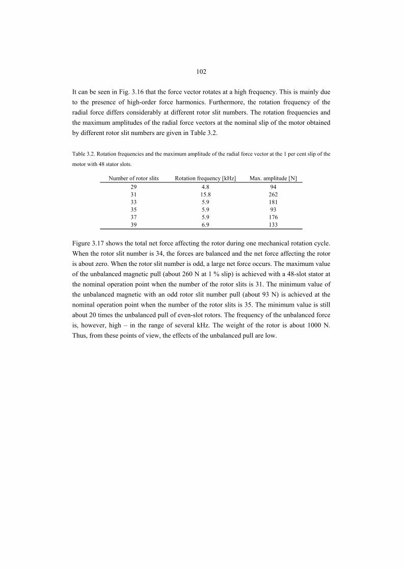
102
It can be seen in Fig. 3.16 that the force vector rotates at a high frequency. This is mainly due to the presence of high-order force harmonics. Furthermore, the rotation frequency of the radial force differs considerably at different rotor slit numbers. The rotation frequencies and the maximum amplitudes of the radial force vectors at the nominal slip of the motor obtained by different rotor slit numbers are given in Table 3.2. Table 3.2. Rotation frequencies and the maximum amplitude of the radial force vector at the 1 per cent slip of the
motor with 48 stator slots.
Number of rotor slits Rotation frequency [kHz] Max. amplitude [N]29 4.8 9431 15.8 26233 5.9 18135 5.9 9337 5.9 17639 6.9 133
Figure 3.17 shows the total net force affecting the rotor during one mechanical rotation cycle. When the rotor slit number is 34, the forces are balanced and the net force affecting the rotor is about zero. When the rotor slit number is odd, a large net force occurs. The maximum value of the unbalanced magnetic pull (about 260 N at 1 % slip) is achieved with a 48-slot stator at the nominal operation point when the number of the rotor slits is 31. The minimum value of the unbalanced magnetic with an odd rotor slit number pull (about 93 N) is achieved at the nominal operation point when the number of the rotor slits is 35. The minimum value is still about 20 times the unbalanced pull of even-slot rotors. The frequency of the unbalanced force is, however, high – in the range of several kHz. The weight of the rotor is about 1000 N. Thus, from these points of view, the effects of the unbalanced pull are low.
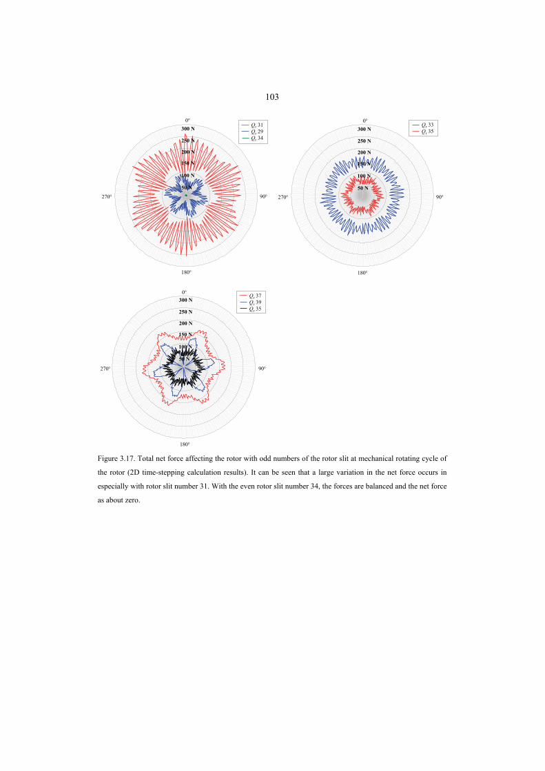
103
Qr 33Qr 35300 N
250 N
200 N
150 N
100 N
50 N
0°
90°270°
180°
Qr 31Qr 29Qr 34
300 N
250 N
200 N
150 N
100 N
50 N
0°
90°270°
180°
Qr 37Qr 39Qr 35
0°
90°270°
180°
300 N
250 N
200 N
150 N
100 N
50 N
Figure 3.17. Total net force affecting the rotor with odd numbers of the rotor slit at mechanical rotating cycle of
the rotor (2D time-stepping calculation results). It can be seen that a large variation in the net force occurs in
especially with rotor slit number 31. With the even rotor slit number 34, the forces are balanced and the net force
as about zero.
104
3.3 Conclusions
Slitting and its mechanical and performance effects were studied in this chapter. It was observed that a suitable number of rotor slits of correct depth produces the best efficiency and the best power factor for a solid rotor. In this case, the best electromechanical performance at the rated torque was achieved when the rotor slit number was 34 and the slits were of even depth of about 60 % of the rotor radius. The rotor mechanical strength, however, limits the practical slit depth to about 40–50 % of the rotor radius. The motor behaviour with odd rotor slit numbers was also analyzed. Odd numbers of rotor slits produce significant unbalanced magnetic pull at a high frequency. The unbalanced magnetic pull is at least 20 times larger with odd slit numbers compared with even rotor slit numbers. Although the unbalanced net force does not exceed the weight of the rotor, the force is quite large and should therefore be considered with special care. It was also found that the torque ripple of odd-slit-number rotors may however be lower than that of even-slit-number rotors.
105
4. COATING OF A SOLID STEEL ROTOR
When designing medium-speed, solid-rotor induction motors, special attention has to be paid on the elimination of the air gap harmonic fields. Three different factors cause harmonic distortion on the rotor surface flux density: 1. spatial stator winding harmonics, 2. stator slot openings and 3. time harmonics in the supply current. The induced fundamental eddy-currents on the rotor surface contribute to the normal operation of the machine, but the eddy-currents induced by the harmonic fields cause harmful additional losses. The higher the electrical conductivity of the rotor material is, the higher are the induced eddy-currents on the rotor. In machines with correctly designed short pitch stator windings, the flux density waveform distortion is mainly due to the permeance variations caused by the stator slot openings. The more distorted the air gap flux density waveform is, the more rotor eddy-current losses are generated. Because of high peripheral speeds, this phenomenon is emphasized in high-speed motors. Also frequency converter supplies contribute to extra losses in high-speed machines, since the voltage pulse width modulation causes additional time-harmonic components to the air gap flux. The change in the local permeance between the stator and the rotor causes a change in the air gap flux below the slot openings, which can be estimated for instance by the method proposed by Heller (1977). An efficient and commonly applied method to reduce the effects of the permeance harmonics on the rotor surface that are mainly caused by the stator slotting is to increase the air gap length. A long air gap length settles down the flux density distortion before it reaches the rotor surface. However, it also decreases the magnetizing inductance over the air gap of the motor and leads to a larger stator current. The magnetizing inductance of a rotating field winding is proportional to the pole pitch τp and inversely proportional to the pole pair number p. For instance, Vogt (1996) gives the formula for the magnetizing inductance Lm, which in the case of a three-phase machine is
( )ii
p210m
1π4
21
23
ατ
pLNξμL
δ= , (4.1)
where Nξ1 is the effective number of turns, δi is the equivalent air gap length and αi is the main flux saturation factor. To get acceptable power factors and to limit the frequency dependent losses, we usually have to adopt the use p = 1 constructions for solid-rotor high- speed induction machines. The further reduction of the air gap flux variation due to the slot permeance harmonics can be achieved by selecting as small stator slot number as the constructional factors allow. However, a small number of stator slots causes a larger amount of winding harmonics, and
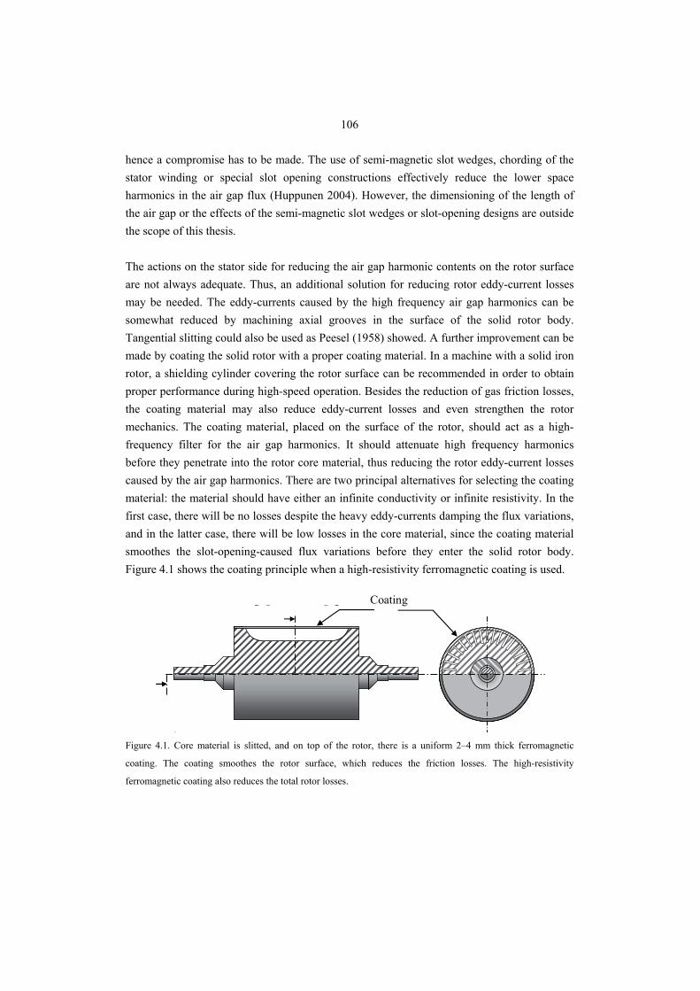
106
hence a compromise has to be made. The use of semi-magnetic slot wedges, chording of the stator winding or special slot opening constructions effectively reduce the lower space harmonics in the air gap flux (Huppunen 2004). However, the dimensioning of the length of the air gap or the effects of the semi-magnetic slot wedges or slot-opening designs are outside the scope of this thesis. The actions on the stator side for reducing the air gap harmonic contents on the rotor surface are not always adequate. Thus, an additional solution for reducing rotor eddy-current losses may be needed. The eddy-currents caused by the high frequency air gap harmonics can be somewhat reduced by machining axial grooves in the surface of the solid rotor body. Tangential slitting could also be used as Peesel (1958) showed. A further improvement can be made by coating the solid rotor with a proper coating material. In a machine with a solid iron rotor, a shielding cylinder covering the rotor surface can be recommended in order to obtain proper performance during high-speed operation. Besides the reduction of gas friction losses, the coating material may also reduce eddy-current losses and even strengthen the rotor mechanics. The coating material, placed on the surface of the rotor, should act as a high-frequency filter for the air gap harmonics. It should attenuate high frequency harmonics before they penetrate into the rotor core material, thus reducing the rotor eddy-current losses caused by the air gap harmonics. There are two principal alternatives for selecting the coating material: the material should have either an infinite conductivity or infinite resistivity. In the first case, there will be no losses despite the heavy eddy-currents damping the flux variations, and in the latter case, there will be low losses in the core material, since the coating material smoothes the slot-opening-caused flux variations before they enter the solid rotor body. Figure 4.1 shows the coating principle when a high-resistivity ferromagnetic coating is used.
c)
Coating
Figure 4.1. Core material is slitted, and on top of the rotor, there is a uniform 2–4 mm thick ferromagnetic
coating. The coating smoothes the rotor surface, which reduces the friction losses. The high-resistivity
ferromagnetic coating also reduces the total rotor losses.
107
The effect of the rotor coating with a high-conductivity low-permeability material on the rotor losses in the case of smooth solid-rotor machines has been studied extensively; the results of these studies are reported by Lähteenmäki (2002). An analytical model for the selection of the copper coating thickness in the case of high-speed synchronous machines was introduced by Shah (2006). It was shown that in order to reduce the total rotor losses, the copper coating thickness must be carefully determined in conjunction with the air gap length and all the significant air gap harmonics. However, it is significant to realize that the manufacturing of a copper-coated rotor is a complicated and expensive process. Thus, the rotor with a copper coating is not always the most desired or even practical solid rotor construction. The use of a high-conductivity material will not be discussed further here, since the use of, for instance, copper on a large rotor surface is difficult from the manufacturing point of view and, especially, in this very case it was not allowed by the rotor environment. It may, however be mentioned that, in principle a copper coating is a good alternative from the electro magnetic performance point of view. An alternative approach is to cover the solid rotor surface for instance with high-resistivity ferromagnetic stainless steel. The high-resistivity coating material for the solid iron rotor should be selected such that it can be firmly attached on the rotor iron by welding, thus boosting the rigidity of the slitted solid rotor construction. The coating may be manufactured by using a stainless ferromagnetic tube, which may be welded to every tooth and the ends. This procedure may significantly strengthen the slitted rotor construction and ease the fulfilment of the mechanical requirements set by the high circumferential velocity of the rotor. In addition that the sleeve closes the rotor surface and thus reduces the gas friction losses, it should also have a tendency to damp the losses induced by the eddy-currents. In this chapter, the possibility and the effect of coating the slitted solid rotor with high-resistivity ferromagnetic material is discussed. A series of finite element calculations was performed to analyze the effect of the rotor coating material electrical resistivity, initial relative permeability and saturation flux density on the induced rotor eddy-current losses.
108
4.1 Motor Performance with a Coated Solid Rotor
When the rotor is coated with a high-resistivity ferromagnetic material, a high-surface impedance is achieved to damp the air gap harmonic effects in the coating layer. The surface impedance for the corresponding flux wave may be defined as a relation between the electric and magnetic field strengths. The highest value of the rotor surface impedance Zrs can be obtained when the coating material has a high permeability and a low conductivity. If the medium has a high surface impedance, it damps the magnetic flux variations trying to penetrate through it. If the surface impedance of a coating material is large, it offers the flux density variations, without causing large losses, to settle down before penetrating into the well-conducting rotor core material. According to the knowledge of the author, for the practical commercially available ferromagnetic materials, the range of electrical resistivity is somewhere between 10 μΩcm and 140 μΩcm. To determine the effect of the rotor coating layer on the motor performance, and especially on its rotor losses, the resistivity, initial relative permeability and the saturation flux density of the coating material were varied. Figures 4.2–4.4 show the FEM-calculated rotor losses in the 120 kW two-pole solid iron rotor. The thickness of the coating layer was 3 mm and the length of the air gap was 2.5 mm. The number of rotor slits was 34 and the number of stator slots was 48. The inner diameter of the stator and the mechanical air gap length were kept constant in all the calculations to obtain comparable results. The rotor core material beneath the coating layer has a resistivity of 30 μΩcm, a saturation flux density of 2 T and an initial relative permeability of 1000. The initial relative permeability for the coating material was 200 and the saturation flux density was 1 T. These values were selected, because such materials are available in practice. It can be seen in Figs. 4.2–4.4 that the electrical resistivity is dominating; the higher the resistivity, the more effectively the rotor losses are reduced. According to Fig. 4.2, if the coating material resistivity is higher than the corresponding value of the rotor core material, the rotor losses are reduced. The effects of the initial permeability and saturation flux density of the coating material on the rotor losses are small. However, the results indicate that the saturation flux density and the initial relative permeability of the rotor coating material should be high. It should be noted that when the rotor is coated, the effect of the rotor slitting on the rotor surface is partly lost. Therefore, in Fig. 4.2 the rotor losses are slightly higher compared with the uncoated rotor, although the resistivities of the coating and the rotor core material are the same.
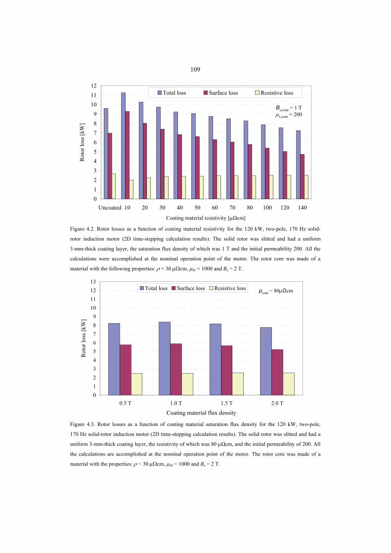
109
Coating material resistivity [μΩcm]
0123456789
101112
Uncoated 10 20 30 40 50 60 70 80 100 120 140
Rot
or lo
ss [k
W]
Total loss Surface loss Resistive loss
Bs,coat = 1 Tμr,coat = 200
Figure 4.2. Rotor losses as a function of coating material resistivity for the 120 kW, two-pole, 170 Hz solid-
rotor induction motor (2D time-stepping calculation results). The solid rotor was slitted and had a uniform
3-mm-thick coating layer, the saturation flux density of which was 1 T and the initial permeability 200. All the
calculations were accomplished at the nominal operation point of the motor. The rotor core was made of a
material with the following properties: ρ = 30 μΩcm, μr0 = 1000 and Bs = 2 T.
0123456789
10111213
0.5 T 1.0 T 1.5 T 2.0 T
Coating material flux density
Rot
or lo
ss [k
W]
Total loss Surface loss Resistive loss ρcoat = 80μΩcm
Figure 4.3. Rotor losses as a function of coating material saturation flux density for the 120 kW, two-pole,
170 Hz solid-rotor induction motor (2D time-stepping calculation results). The solid rotor was slitted and had a
uniform 3-mm-thick coating layer, the resistivity of which was 80 μΩcm, and the initial permeability of 200. All
the calculations are accomplished at the nominal operation point of the motor. The rotor core was made of a
material with the properties: ρ = 30 μΩcm, μr0 = 1000 and Bs = 2 T.
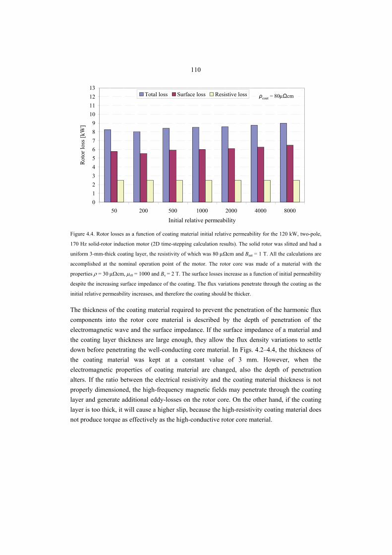
110
0123456789
10111213
50 200 500 1000 2000 4000 8000
Initial relative permeability
Rot
or lo
ss [k
W]
Total loss Surface loss Resistive loss ρcoat = 80μΩcm
Figure 4.4. Rotor losses as a function of coating material initial relative permeability for the 120 kW, two-pole,
170 Hz solid-rotor induction motor (2D time-stepping calculation results). The solid rotor was slitted and had a
uniform 3-mm-thick coating layer, the resistivity of which was 80 μΩcm and Bsat = 1 T. All the calculations are
accomplished at the nominal operation point of the motor. The rotor core was made of a material with the
properties ρ = 30 μΩcm, μr0 = 1000 and Bs = 2 T. The surface losses increase as a function of initial permeability
despite the increasing surface impedance of the coating. The flux variations penetrate through the coating as the
initial relative permeability increases, and therefore the coating should be thicker.
The thickness of the coating material required to prevent the penetration of the harmonic flux components into the rotor core material is described by the depth of penetration of the electromagnetic wave and the surface impedance. If the surface impedance of a material and the coating layer thickness are large enough, they allow the flux density variations to settle down before penetrating the well-conducting core material. In Figs. 4.2–4.4, the thickness of the coating material was kept at a constant value of 3 mm. However, when the electromagnetic properties of coating material are changed, also the depth of penetration alters. If the ratio between the electrical resistivity and the coating material thickness is not properly dimensioned, the high-frequency magnetic fields may penetrate through the coating layer and generate additional eddy-losses on the rotor core. On the other hand, if the coating layer is too thick, it will cause a higher slip, because the high-resistivity coating material does not produce torque as effectively as the high-conductive rotor core material.
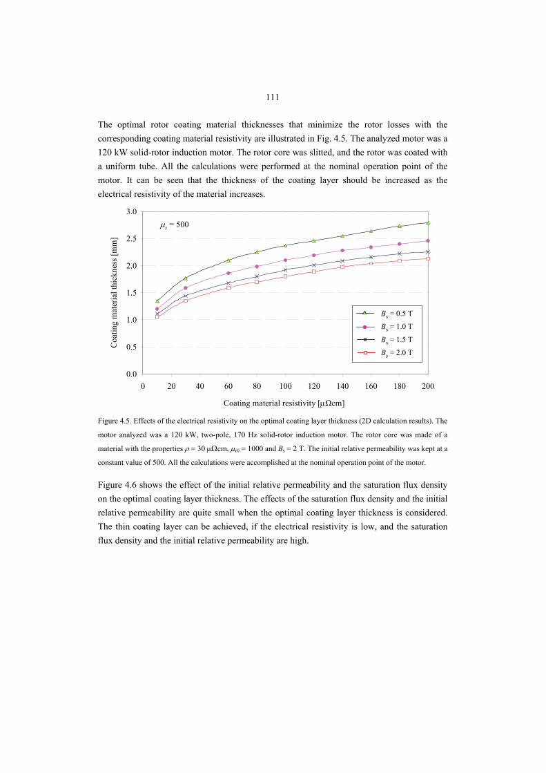
111
The optimal rotor coating material thicknesses that minimize the rotor losses with the corresponding coating material resistivity are illustrated in Fig. 4.5. The analyzed motor was a 120 kW solid-rotor induction motor. The rotor core was slitted, and the rotor was coated with a uniform tube. All the calculations were performed at the nominal operation point of the motor. It can be seen that the thickness of the coating layer should be increased as the electrical resistivity of the material increases.
0.0
0.5
1.0
1.5
2.0
2.5
3.0
0 20 40 60 80 100 120 140 160 180 200
Coating material resistivity [μΩcm]
Coa
ting
mat
eria
l thi
ckne
ss [m
m]
Bs = 0.5 T
Bs = 1.0 T
Bs = 1.5 T
Bs = 2.0 T
μr = 500
Figure 4.5. Effects of the electrical resistivity on the optimal coating layer thickness (2D calculation results). The
motor analyzed was a 120 kW, two-pole, 170 Hz solid-rotor induction motor. The rotor core was made of a
material with the properties ρ = 30 μΩcm, μr0 = 1000 and Bs = 2 T. The initial relative permeability was kept at a
constant value of 500. All the calculations were accomplished at the nominal operation point of the motor.
Figure 4.6 shows the effect of the initial relative permeability and the saturation flux density on the optimal coating layer thickness. The effects of the saturation flux density and the initial relative permeability are quite small when the optimal coating layer thickness is considered. The thin coating layer can be achieved, if the electrical resistivity is low, and the saturation flux density and the initial relative permeability are high.
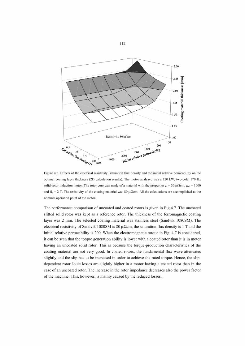
112
0.51.0
1.5
2.0
50200
5001000
20004000
8000
1.00
1.25
1.50
1.75
2.00
2.25
2.50
Initial relative permeabilitySaturation flux density [T]
Coa
ting
mat
eria
l thi
ckne
ss [m
m]
0.51.0
1.5
2.0
50200
5001000
20004000
8000
1.00
1.25
1.50
1.75
2.00
2.25
2.50
Initial relative permeabilitySaturation flux density [T]
Coa
ting
mat
eria
l thi
ckne
ss [m
m]
Resistivity 80 μΩcm
Figure 4.6. Effects of the electrical resistivity, saturation flux density and the initial relative permeability on the
optimal coating layer thickness (2D calculation results). The motor analyzed was a 120 kW, two-pole, 170 Hz
solid-rotor induction motor. The rotor core was made of a material with the properties ρ = 30 μΩcm, μr0 = 1000
and Bs = 2 T. The resistivity of the coating material was 80 μΩcm. All the calculations are accomplished at the
nominal operation point of the motor.
The performance comparison of uncoated and coated rotors is given in Fig 4.7. The uncoated slitted solid rotor was kept as a reference rotor. The thickness of the ferromagnetic coating layer was 2 mm. The selected coating material was stainless steel (Sandvik 1080SM). The electrical resistivity of Sandvik 1080SM is 80 μΩcm, the saturation flux density is 1 T and the initial relative permeability is 200. When the electromagnetic torque in Fig. 4.7 is considered, it can be seen that the torque generation ability is lower with a coated rotor than it is in motor having an uncoated solid rotor. This is because the torque-production characteristics of the coating material are not very good. In coated rotors, the fundamental flux wave attenuates slightly and the slip has to be increased in order to achieve the rated torque. Hence, the slip-dependent rotor Joule losses are slightly higher in a motor having a coated rotor than in the case of an uncoated rotor. The increase in the rotor impedance decreases also the power factor of the machine. This, however, is mainly caused by the reduced losses.
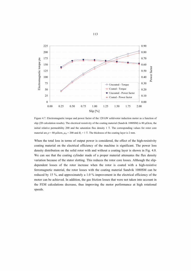
113
0
25
50
75
100
125
150
175
200
225
0.00 0.25 0.50 0.75 1.00 1.25 1.50 1.75 2.00
Slip [%]
Elec
trom
agne
tic to
rque
pu
0.00
0.10
0.20
0.30
0.40
0.50
0.60
0.70
0.80
0.90
Pow
er fa
ctor
Uncoated - TorqueCoated - TorqueUncoated - Power factorCoated - Power factor
Figure 4.7. Electromagnetic torque and power factor of the 120 kW solid-rotor induction motor as a function of
slip (2D calculation results). The electrical resistivity of the coating material (Sandvik 1080SM) is 80 μΩcm, the
initial relative permeability 200 and the saturation flux density 1 T. The corresponding values for rotor core
material are ρ = 80 μΩcm, μr0 = 200 and Bs = 1 T. The thickness of the coating layer is 2 mm.
When the total loss in terms of output power is considered, the effect of the high-resistivity coating material on the electrical efficiency of the machine is significant. The power loss density distribution on the solid rotor with and without a coating layer is shown in Fig. 4.8. We can see that the coating cylinder made of a proper material attenuates the flux density variation because of the stator slotting. This reduces the rotor core losses. Although the slip-dependent losses of the rotor increase when the rotor is coated with a high-resistive ferromagnetic material, the rotor losses with the coating material Sandvik 1080SM can be reduced by 15 %, and approximately a 1.0 % improvement in the electrical efficiency of the motor can be achieved. In addition, the gas friction losses that were not taken into account in the FEM calculations decrease, thus improving the motor performance at high rotational speeds.
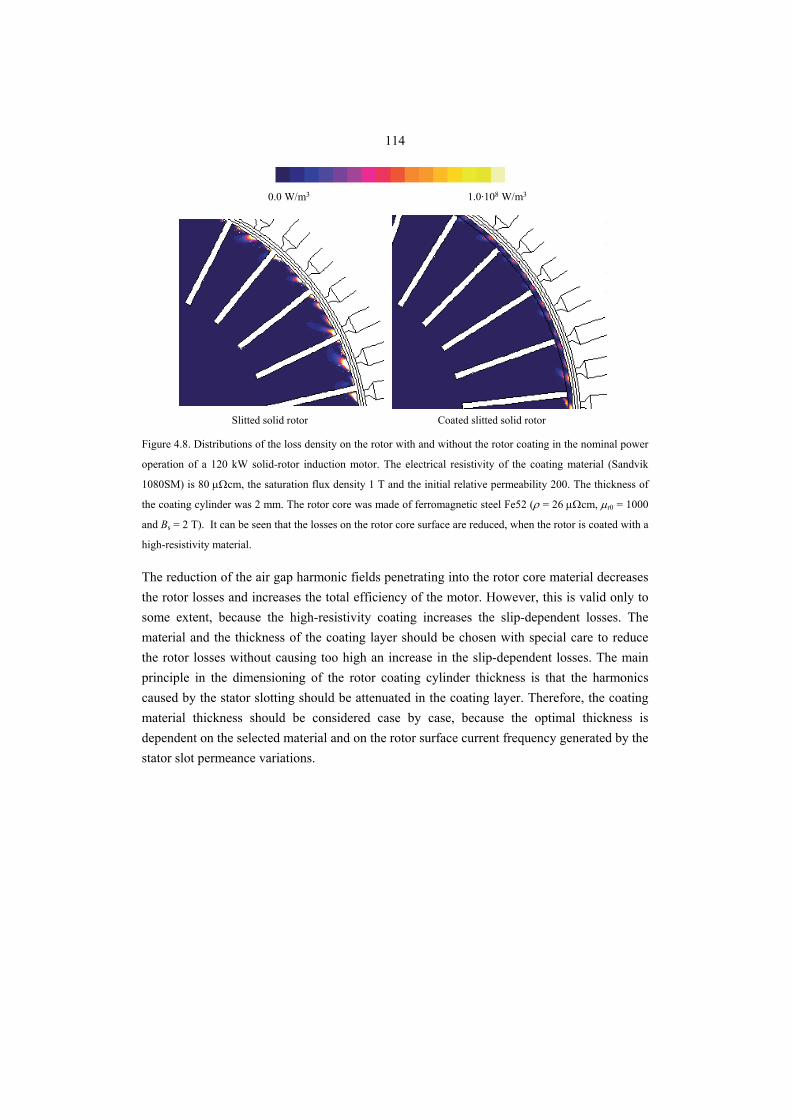
114
Slitted solid rotor Slitted coated solid rotor
0.0 W/m3 1.0·108 W/m3
Slitted solid rotor Coated slitted solid rotor Figure 4.8. Distributions of the loss density on the rotor with and without the rotor coating in the nominal power
operation of a 120 kW solid-rotor induction motor. The electrical resistivity of the coating material (Sandvik
1080SM) is 80 μΩcm, the saturation flux density 1 T and the initial relative permeability 200. The thickness of
the coating cylinder was 2 mm. The rotor core was made of ferromagnetic steel Fe52 (ρ = 26 μΩcm, μr0 = 1000
and Bs = 2 T). It can be seen that the losses on the rotor core surface are reduced, when the rotor is coated with a
high-resistivity material.
The reduction of the air gap harmonic fields penetrating into the rotor core material decreases the rotor losses and increases the total efficiency of the motor. However, this is valid only to some extent, because the high-resistivity coating increases the slip-dependent losses. The material and the thickness of the coating layer should be chosen with special care to reduce the rotor losses without causing too high an increase in the slip-dependent losses. The main principle in the dimensioning of the rotor coating cylinder thickness is that the harmonics caused by the stator slotting should be attenuated in the coating layer. Therefore, the coating material thickness should be considered case by case, because the optimal thickness is dependent on the selected material and on the rotor surface current frequency generated by the stator slot permeance variations.
115
4.2 Conclusions
Coating of a solid rotor with a suitable ferromagnetic material may considerably improve the performance of a solid-rotor induction motor. The material properties and the thickness of the coating material must, however, be carefully selected. The effects of the coating material resistivity, initial permeability and saturation flux density on the rotor losses were studied. As a practical coating material example, one commercial ferromagnetic stainless steel was studied. This material has a resistivity of about 80 μΩcm, a saturation of about 1 T and an initial permeability of about 200. Using this material as a coating material improved the efficiency of the 120 kW machine by one per cent unit. If higher resistivity materials were available, the improvement would even be greater. Using a coating that closes the rotor surface may be problematic in a machine that operates at ambient pressure, since the effective cooling surface of the rotor is significantly reduced by the coating. The coating may, however, be highly beneficial, if the air gap pressure is high and the decrease in the rotor surface caused by the coating does not disturb the heat transfer of the rotor. In such a case, the friction losses are also considerably smaller, and the effect of the rotor coating may be remarkable.
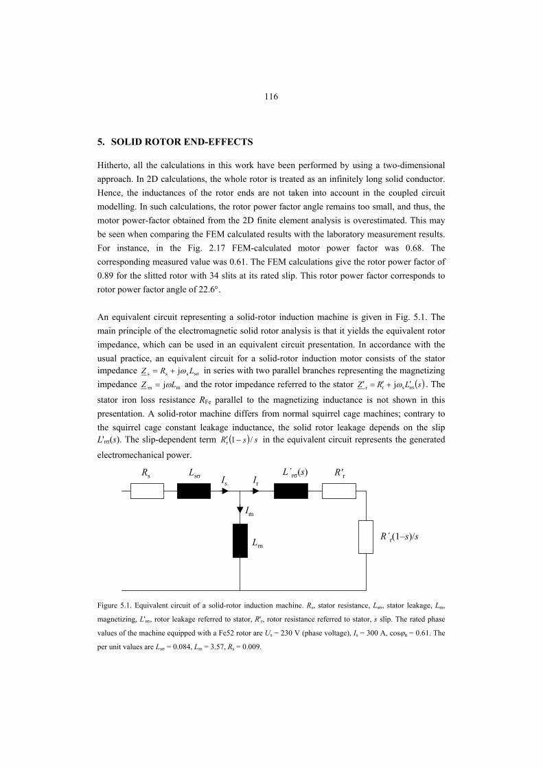
116
5. SOLID ROTOR END-EFFECTS
Hitherto, all the calculations in this work have been performed by using a two-dimensional approach. In 2D calculations, the whole rotor is treated as an infinitely long solid conductor. Hence, the inductances of the rotor ends are not taken into account in the coupled circuit modelling. In such calculations, the rotor power factor angle remains too small, and thus, the motor power-factor obtained from the 2D finite element analysis is overestimated. This may be seen when comparing the FEM calculated results with the laboratory measurement results. For instance, in the Fig. 2.17 FEM-calculated motor power factor was 0.68. The corresponding measured value was 0.61. The FEM calculations give the rotor power factor of 0.89 for the slitted rotor with 34 slits at its rated slip. This rotor power factor corresponds to rotor power factor angle of 22.6°. An equivalent circuit representing a solid-rotor induction machine is given in Fig. 5.1. The main principle of the electromagnetic solid rotor analysis is that it yields the equivalent rotor impedance, which can be used in an equivalent circuit presentation. In accordance with the usual practice, an equivalent circuit for a solid-rotor induction motor consists of the stator impedance sσsss j LRZ ω+= in series with two parallel branches representing the magnetizing impedance mm j LZ ω= and the rotor impedance referred to the stator ( )sLRZ rσsrr j ′+′=′ ω . The
stator iron loss resistance RFe parallel to the magnetizing inductance is not shown in this presentation. A solid-rotor machine differs from normal squirrel cage machines; contrary to the squirrel cage constant leakage inductance, the solid rotor leakage depends on the slip L'rσ(s). The slip-dependent term ( ) ssR /1r −′ in the equivalent circuit represents the generated
electromechanical power.
Lm
Rs Lsσ L´rσ(s) R′r
R´r(1–s)/s
IrIs
Im
Figure 5.1. Equivalent circuit of a solid-rotor induction machine. Rs, stator resistance, Lsσ, stator leakage, Lm,
magnetizing, L'rσ, rotor leakage referred to stator, R'r, rotor resistance referred to stator, s slip. The rated phase
values of the machine equipped with a Fe52 rotor are Us = 230 V (phase voltage), Is = 300 A, cosϕn = 0.61. The
per unit values are Lsσ = 0.084, Lm = 3.57, Rs = 0.009.
117
The rotor surface impedance Zr seen by an axial electric field Ê0 at the surface of the solid rotor can be expressed in the form
0
0
s
0r ˆ
ˆˆˆ
HnE
JE
×==Z , (5.1)
where n is the unit vector normal to the surface, 0H is the magnetic field strength at the surface of the solid rotor, and sJ presents the induced rotor surface current in A/m. The finite
element field solution, hence, gives the rotor impedance and its phase angle. The linear theory of eddy-currents in solid conductors is well known and documented. In the linear analysis, it is assumed that the active part and the reactive part of the surface impedance are equal and constant. This results in a rotor surface impedance as
( ) o452
j1j1rs
sliplinearr, ∠=+=
+= Z
σμω
δσZ . (5.2)
In Eq. (5.2) the depth of penetration of the electromagnetic wave into the conducting material is defined as
σμslipdp
2ω
δ = , (5.3)
where σ is the electrical conductivity of the material and ωslip is the angular frequency of the penetrating field. In the linear theory, it is assumed that the penetration depth of the penetrating field is calculated with a constant permeability μ. When the active and reactive parts of the surface impedance are considered to be equal, there is a 45° phase shift between the electric field strength and the surface current. This produces for a non-saturating rotor a power factor of cosϕ r = 0.707. This is contrary to many results obtained with practical experiments, which have shown that the phase angle of solid rotor is far less than 45°. This can be explained with the fact that the ferromagnetic steel saturates and a constant value of μ cannot satisfactorily represent the nonlinear magnetic behaviour of the rotor steel. Agarwal’s limiting non-linear theory (1959) assumes idealized rectangular magnetization characteristics. In Agarwal’s model, it is assumed that the flux density within the material may exist only at a magnitude to a saturation level. The depth of penetration is defined as in the linear theory, except that the permeability μ is defined in terms of the peak value of the sinusoidal applied surface magnetic field 0H and the saturation value of magnetic field flux
density Bs
118
s
0dp
ˆ22ωσB
Hωσμ
δ == . (5.4)
In the case of a sinusoidal imposed tangential magnetic field, the rotor surface impedance according to Agarwal’s limiting non-linear theory, that is Zr,non-linear is
( ) o6.26π3
58j2π38j
m
mAgarwalAgarwallinear-nonr, ∠=+=+=
σδσδHHXRZ . (5.5)
According to Agarwal's limiting non-linear theory, the phase shift for a totally saturated rotor is 26.6 degrees. This gives a rotor power factor of cosϕr = 0.894. Correspondingly sinϕr = 0.448. Hence, Agarwal’s limiting non-linear theory suggests that there are a per unit resistance of 0.894 and a corresponding per unit inductive reactance of 0.448 in the rotor. In practice, the rotor power factor is somewhat lower. Both the linear theory and the limiting non-linear theory produce a constant power factor for the rotor impedance. An approximate solution obtained by assuming the permeability to be constant may yield good results as long as the material remains on the linear portion of the magnetization curve. This, however, takes place only at very small slips. At rated operation points of typical solid-rotor machines, the rotor surfaces are heavily saturated and their behaviour approaches Agarwal's non-limiting theory. Assuming heavy saturation, the rotor phase angle ϕ r approaches the theoretical value of 26.6° given by Agarwal’s theory. If the saturation is lower, the rotor phase angle starts to approach the value of 45° given by the linear theory. It is assumed that the phase angle of the rotor impedance is somewhere between these two extremes, given by the linear theory and the limiting non-linear theory. Pillai (1969) used a non-linear variation of fundamental BH curve in the calculations. It was concluded that the rotor impedance phase angle varies between 35.3° and 45°. Test results showed that the real phase angle of the rotor impedance approaches the lower value when the slip increases and the magnetic field strength drives the surface of the rotor steel into the magnetic saturation. Respectively, at very low slips the magnetic state of the rotor is lighter and the phase angle approaches 45°. Figure 5.2 shows the phasor diagram of the solid-rotor induction motor studied. In the figure, Lsσ is the leakage inductance of the stator, Lm is the magnetizing inductance of the machine at the nominal point, L'rσ is the rotor leakage inductance of the machine referred to the stator, R'r is the rotor resistance referred to the stator and Ir is the rotor current. Because of a very low value of the stator per unit resistance, the voltage loss caused by the stator winding resistance Rs is neglected in the phasor diagram. The slip is represented with the symbol s. Ψs is the stator flux linkage, which includes the air gap flux linkage Ψm and the stator flux leakage Ψsσ. Correspondingly, Ψr is the flux linkage of the rotor, which includes the air gap flux linkage Ψm and the rotor flux leakage Ψrσ. The stator voltage Us creates the stator flux linkage, of
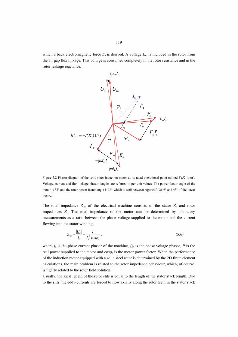
119
which a back electromagnetic force Es is derived. A voltage Em is included in the rotor from the air gap flux linkage. This voltage is consumed completely in the rotor resistance and in the rotor leakage reactance.
Im
−I'r
Is
Ψs
Ψm
Ψ r'
Em
ϕr
Es
Us Um
= −I'rR'r(1/s)
−I'r
E'r
ssσIL
rrσIL ′′
ssσj ILω
rrσj IL ′′− ω
ssσj ILω−
ϕ s
Figure 5.2 Phasor diagram of the solid-rotor induction motor at its rated operational point (slitted Fe52 rotor).
Voltage, current and flux linkage phasor lengths are referred to per unit values. The power factor angle of the
motor is 52° and the rotor power factor angle is 36° which is well between Agarwal's 26.6° and 45° of the linear
theory.
The total impedance Ztot of the electrical machine consists of the stator Zs and rotor impedances Zr. The total impedance of the motor can be determined by laboratory measurements as a ratio between the phase voltage supplied to the motor and the current flowing into the stator winding
s2
ss
stot cosϕI
PI
UZ == , (5.6)
where Is is the phase current phasor of the machine, Us is the phase voltage phasor, P is the real power supplied to the motor and cosφs is the motor power factor. When the performance of the induction motor equipped with a solid steel rotor is determined by the 2D finite element calculations, the main problem is related to the rotor impedance behaviour, which, of course, is tightly related to the rotor field solution. Usually, the axial length of the rotor slits is equal to the length of the stator stack length. Due to the slits, the eddy-currents are forced to flow axially along the rotor teeth in the stator stack
120
region. The rotor end-regions that are beyond the laminated stator core short-circuit the rotor teeth and act as “end-rings” made of ferromagnetic material. 2D calculations are not capable of taking the magnetic fields of the end-areas into account and, hence, the three-dimensional rotor end-effects should be taken into account with a complex corrective end-effect factor ker. The rotor impedance, fixed with end-factor is
rerfix ZkZ = . (5.7)
The end-effect factor is in principle a complex number, since it should be capable of evaluating also the inductance of the end-region, as the end-region impedance angle might not be the same as in the active areas of the rotor. The phase angle of the rotor impedance is
( ) ( )2rσs
2r
r2
rσr2
r
r
r
rrcos
LsR
R
LR
RZR
ωωϕ
+=
+== . (5.8)
When the rotor is made of one single piece of ferromagnetic material without electrically high-conductive end-rings, the rotor end fields have a significant effect on the motor characteristics. It is obvious that if the effects of the end-areas of a solid steel rotor are not included in the analysis, the rotor impedance will be too small and the output power of the motor will be too optimistic. In two-dimensional numerical finite element calculations, the three dimensional rotor end-effects are traditionally taken into account by modifying the rotor effective resistivity by an end-factor, described, for instance, by Trickey (1936), Russell (1958), Yee (1971), O’Kelly (1972) and Woolley (1973). To take into account the induced eddy-currents flowing peripherally at the ends of the rotor, a variety of correction factors have been suggested to modify the rotor impedance. Further, to take into account the complex three-dimensional current distribution in the end regions of the rotor iron, a full three-dimensional finite element analysis is required. However, modelling of the whole solid-rotor induction motor with the three-dimensional time-stepping finite element method is too large a problem for the present-day computers. However, the proposed end-factors can be applied only to the resistive part of the rotor impedance, which may result in a correct torque, but the calculation of the power factor of the rotor and also the motor will indisputably fail. This is demonstrated in Fig 5.3.
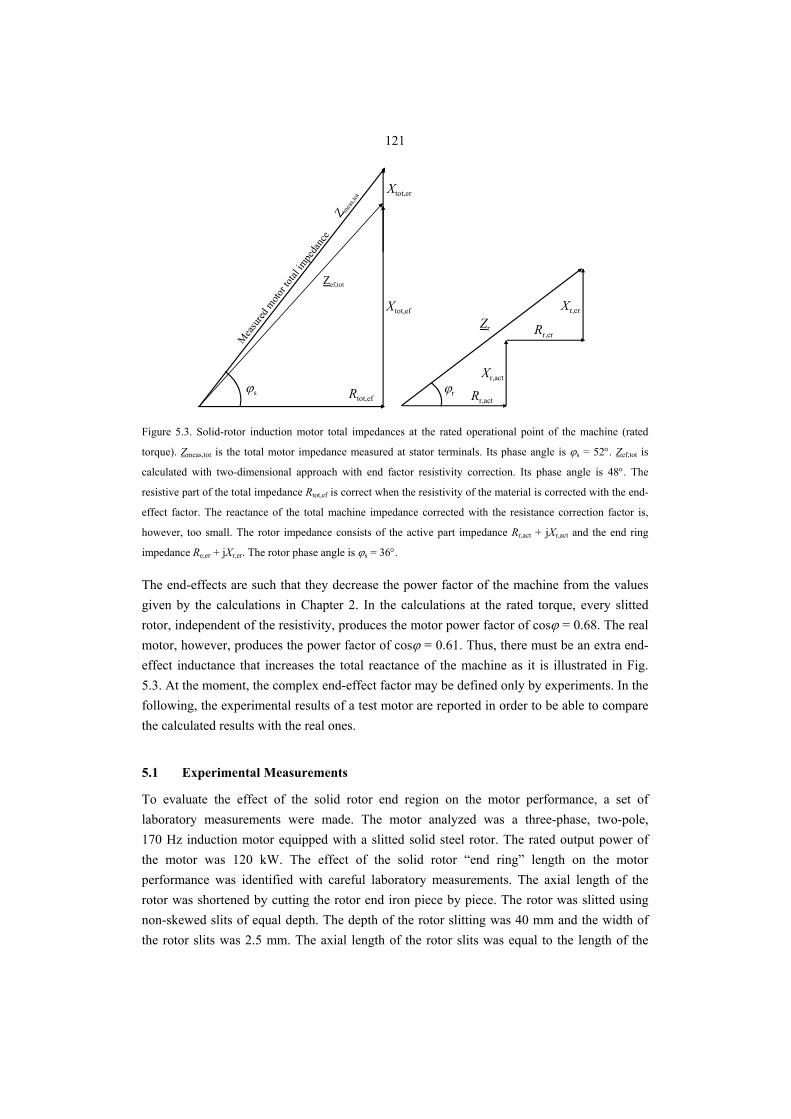
121
Mea
sured
moto
r tota
l impe
danc
e Z mea
s,tot
Zef,tot
Xtot,ef
Xtot,er
Rtot,ef
Zr
Rr,act
Xr,act
Rr,er
Xr,er
ϕs ϕr
Figure 5.3. Solid-rotor induction motor total impedances at the rated operational point of the machine (rated
torque). Zmeas,tot is the total motor impedance measured at stator terminals. Its phase angle is ϕs = 52°. Zef,tot is
calculated with two-dimensional approach with end factor resistivity correction. Its phase angle is 48°. The
resistive part of the total impedance Rtot,ef is correct when the resistivity of the material is corrected with the end-
effect factor. The reactance of the total machine impedance corrected with the resistance correction factor is,
however, too small. The rotor impedance consists of the active part impedance Rr,act + jXr,act and the end ring
impedance Re,er + jXr,er. The rotor phase angle is ϕs = 36°.
The end-effects are such that they decrease the power factor of the machine from the values given by the calculations in Chapter 2. In the calculations at the rated torque, every slitted rotor, independent of the resistivity, produces the motor power factor of cosϕ = 0.68. The real motor, however, produces the power factor of cosϕ = 0.61. Thus, there must be an extra end-effect inductance that increases the total reactance of the machine as it is illustrated in Fig. 5.3. At the moment, the complex end-effect factor may be defined only by experiments. In the following, the experimental results of a test motor are reported in order to be able to compare the calculated results with the real ones.
5.1 Experimental Measurements
To evaluate the effect of the solid rotor end region on the motor performance, a set of laboratory measurements were made. The motor analyzed was a three-phase, two-pole, 170 Hz induction motor equipped with a slitted solid steel rotor. The rated output power of the motor was 120 kW. The effect of the solid rotor “end ring” length on the motor performance was identified with careful laboratory measurements. The axial length of the rotor was shortened by cutting the rotor end iron piece by piece. The rotor was slitted using non-skewed slits of equal depth. The depth of the rotor slitting was 40 mm and the width of the rotor slits was 2.5 mm. The axial length of the rotor slits was equal to the length of the
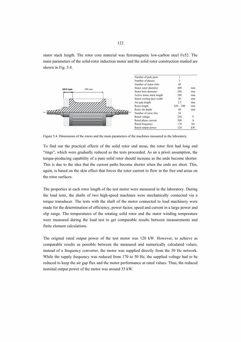
122
stator stack length. The rotor core material was ferromagnetic low-carbon steel Fe52. The main parameters of the solid-rotor induction motor and the solid rotor construction studied are shown in Fig. 5.4.
60-0 mm60-0 mm 300 mm
Number of pole pairs 1Number of phases 3Number of stator slots 48Stator outer diameter 400 mmStator bore diameter 200 mmActive stator stack length 280 mmStator cooling duct width 20 mmAir-gap length 2.5 mmRotor length 420 – 300 mmRotor slit depth 40 mmNumber of rotor slits 34Rated voltage 230 VRated phase current 300 ARated frequency 170 HzRated output power 120 kW
Figure 5.4. Dimensions of the rotors and the main parameters of the machines measured in the laboratory.
To find out the practical effects of the solid rotor end areas, the rotor first had long end "rings", which were gradually reduced as the tests proceeded. As an a priori assumption, the torque-producing capability of a pure solid rotor should increase as the ends become shorter. This is due to the idea that the current paths become shorter when the ends are short. This, again, is based on the skin effect that forces the rotor current to flow in the free end areas on the rotor surfaces. The properties at each rotor length of the test motor were measured in the laboratory. During the load tests, the shafts of two high-speed machines were mechanically connected via a torque transducer. The tests with the shaft of the motor connected to load machinery were made for the determination of efficiency, power factor, speed and current in a large power and slip range. The temperatures of the rotating solid rotor and the stator winding temperature were measured during the load test to get comparable results between measurements and finite element calculations. The original rated output power of the test motor was 120 kW. However, to achieve as comparable results as possible between the measured and numerically calculated values, instead of a frequency converter, the motor was supplied directly from the 50 Hz network. While the supply frequency was reduced from 170 to 50 Hz, the supplied voltage had to be reduced to keep the air gap flux and the motor performance at rated values. Thus, the reduced nominal output power of the motor was around 35 kW.
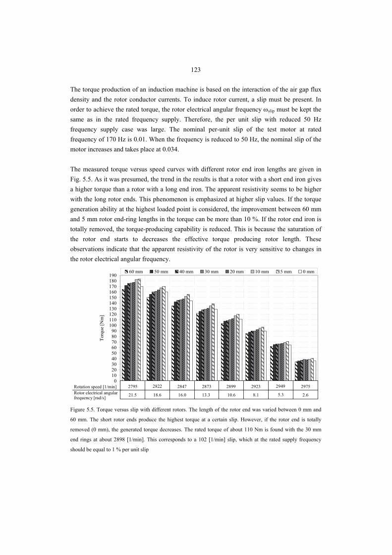
123
The torque production of an induction machine is based on the interaction of the air gap flux density and the rotor conductor currents. To induce rotor current, a slip must be present. In order to achieve the rated torque, the rotor electrical angular frequency ωslip must be kept the same as in the rated frequency supply. Therefore, the per unit slip with reduced 50 Hz frequency supply case was large. The nominal per-unit slip of the test motor at rated frequency of 170 Hz is 0.01. When the frequency is reduced to 50 Hz, the nominal slip of the motor increases and takes place at 0.034. The measured torque versus speed curves with different rotor end iron lengths are given in Fig. 5.5. As it was presumed, the trend in the results is that a rotor with a short end iron gives a higher torque than a rotor with a long end iron. The apparent resistivity seems to be higher with the long rotor ends. This phenomenon is emphasized at higher slip values. If the torque generation ability at the highest loaded point is considered, the improvement between 60 mm and 5 mm rotor end-ring lengths in the torque can be more than 10 %. If the rotor end iron is totally removed, the torque-producing capability is reduced. This is because the saturation of the rotor end starts to decreases the effective torque producing rotor length. These observations indicate that the apparent resistivity of the rotor is very sensitive to changes in the rotor electrical angular frequency.
0102030405060708090
100110120130140150160170180190
Torq
ue [N
m]
60 mm 50 mm 40 mm 30 mm 20 mm 10 mm 5 mm 0 mm
2795 2822 2847 2873 2899 2923 2949 2975
21.5 18.6 16.0 13.3 10.6 8.1 5.3 2.6
Rotation speed [1/min]Rotor electrical angular frequency [rad/s]
Figure 5.5. Torque versus slip with different rotors. The length of the rotor end was varied between 0 mm and
60 mm. The short rotor ends produce the highest torque at a certain slip. However, if the rotor end is totally
removed (0 mm), the generated torque decreases. The rated torque of about 110 Nm is found with the 30 mm
end rings at about 2898 [1/min]. This corresponds to a 102 [1/min] slip, which at the rated supply frequency
should be equal to 1 % per unit slip
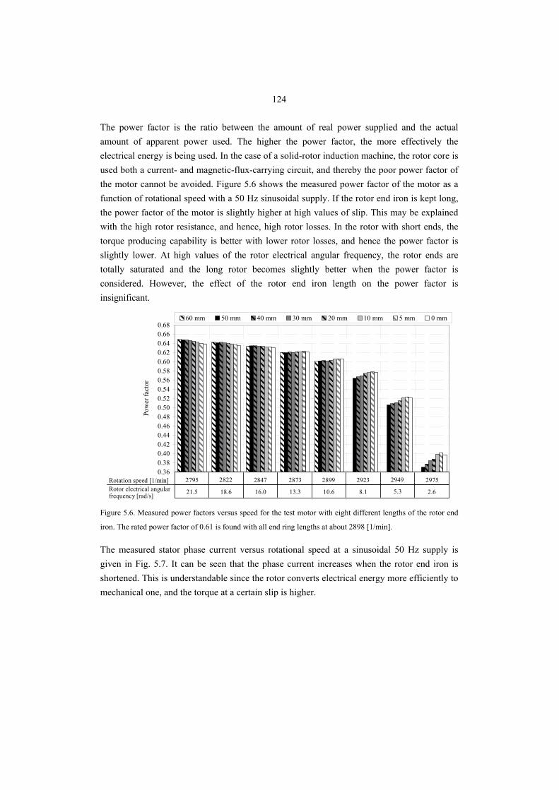
124
The power factor is the ratio between the amount of real power supplied and the actual amount of apparent power used. The higher the power factor, the more effectively the electrical energy is being used. In the case of a solid-rotor induction machine, the rotor core is used both a current- and magnetic-flux-carrying circuit, and thereby the poor power factor of the motor cannot be avoided. Figure 5.6 shows the measured power factor of the motor as a function of rotational speed with a 50 Hz sinusoidal supply. If the rotor end iron is kept long, the power factor of the motor is slightly higher at high values of slip. This may be explained with the high rotor resistance, and hence, high rotor losses. In the rotor with short ends, the torque producing capability is better with lower rotor losses, and hence the power factor is slightly lower. At high values of the rotor electrical angular frequency, the rotor ends are totally saturated and the long rotor becomes slightly better when the power factor is considered. However, the effect of the rotor end iron length on the power factor is insignificant.
0.360.380.400.420.440.460.480.500.520.540.560.580.600.620.640.660.68
2795 2822 2847 2873 2899 2923 2949 2975
Pow
er fa
ctor
60 mm 50 mm 40 mm 30 mm 20 mm 10 mm 5 mm 0 mm
2795 2822 2847 2873 2899 2923 2949 2975
21.5 18.6 16.0 13.3 10.6 8.1 5.3 2.6
Rotation speed [1/min]Rotor electrical angular frequency [rad/s]
Figure 5.6. Measured power factors versus speed for the test motor with eight different lengths of the rotor end
iron. The rated power factor of 0.61 is found with all end ring lengths at about 2898 [1/min].
The measured stator phase current versus rotational speed at a sinusoidal 50 Hz supply is given in Fig. 5.7. It can be seen that the phase current increases when the rotor end iron is shortened. This is understandable since the rotor converts electrical energy more efficiently to mechanical one, and the torque at a certain slip is higher.
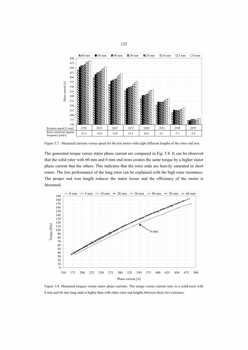
125
150
175
200
225
250275
300
325
350
375400
425
450475
500
2795 2822 2847 2873 2899 2923 2949 2975
Rotation speed [rpm]
Phas
e cu
rren
t [A
]
60 mm 50 mm 40 mm 30 mm 20 mm 10 mm 5 mm 0 mm
2795 2822 2847 2873 2899 2923 2949 2975
21.5 18.6 16.0 13.3 10.6 8.1 5.3 2.6
Rotation speed [1/min]Rotor electrical angular frequency [rad/s]
Figure 5.7. Measured currents versus speed for the test motor with eight different lengths of the rotor end iron.
The generated torque versus stator phase current are compared in Fig. 5.8. It can be observed that the solid rotor with 60 mm and 0 mm end irons creates the same torque by a higher stator phase current that the others. This indicates that the rotor ends are heavily saturated in short rotors. The low performance of the long rotor can be explained with the high rotor resistance. The proper end iron length reduces the stator losses and the efficiency of the motor is increased.
0102030405060708090
100110120130140150160170180190
150 175 200 225 250 275 300 325 350 375 400 425 450 475 500
Phase current [A]
Torq
ue [N
m]
0 mm 5 mm 10 mm 20 mm 30 mm 40 mm 50 mm 60 mm
0 mm
Figure 5.8. Measured torques versus stator phase currents. The torque versus current ratio in a solid-rotor with
0 mm and 60 mm long ends is higher than with other rotor end lengths between these two extremes.
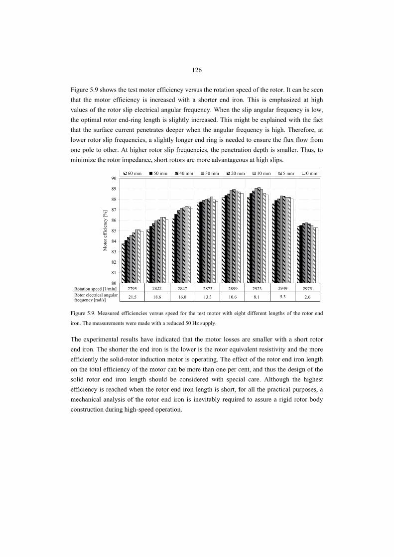
126
Figure 5.9 shows the test motor efficiency versus the rotation speed of the rotor. It can be seen that the motor efficiency is increased with a shorter end iron. This is emphasized at high values of the rotor slip electrical angular frequency. When the slip angular frequency is low, the optimal rotor end-ring length is slightly increased. This might be explained with the fact that the surface current penetrates deeper when the angular frequency is high. Therefore, at lower rotor slip frequencies, a slightly longer end ring is needed to ensure the flux flow from one pole to other. At higher rotor slip frequencies, the penetration depth is smaller. Thus, to minimize the rotor impedance, short rotors are more advantageous at high slips.
80
81
82
83
84
85
86
87
88
89
90
Mot
or e
ffic
ienc
y [%
]
60 mm 50 mm 40 mm 30 mm 20 mm 10 mm 5 mm 0 mm
2795 2822 2847 2873 2899 2923 2949 2975
21.5 18.6 16.0 13.3 10.6 8.1 5.3 2.6
Rotation speed [1/min]Rotor electrical angular frequency [rad/s]
Figure 5.9. Measured efficiencies versus speed for the test motor with eight different lengths of the rotor end
iron. The measurements were made with a reduced 50 Hz supply.
The experimental results have indicated that the motor losses are smaller with a short rotor end iron. The shorter the end iron is the lower is the rotor equivalent resistivity and the more efficiently the solid-rotor induction motor is operating. The effect of the rotor end iron length on the total efficiency of the motor can be more than one per cent, and thus the design of the solid rotor end iron length should be considered with special care. Although the highest efficiency is reached when the rotor end iron length is short, for all the practical purposes, a mechanical analysis of the rotor end iron is inevitably required to assure a rigid rotor body construction during high-speed operation.
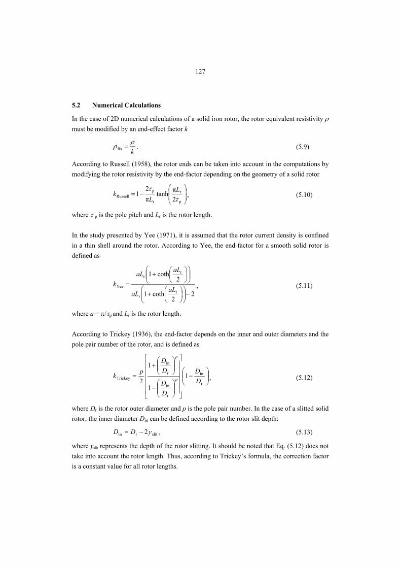
127
5.2 Numerical Calculations
In the case of 2D numerical calculations of a solid iron rotor, the rotor equivalent resistivity ρ must be modified by an end-effect factor k
kρρ =fix . (5.9)
According to Russell (1958), the rotor ends can be taken into account in the computations by modifying the rotor resistivity by the end-factor depending on the geometry of a solid rotor
⎟⎟⎠
⎞⎜⎜⎝
⎛−=
p
r
r
pRussell 2
πtanhπ2
1τ
τ LL
k , (5.10)
where τ p is the pole pitch and Lr is the rotor length. In the study presented by Yee (1971), it is assumed that the rotor current density is confined in a thin shell around the rotor. According to Yee, the end-factor for a smooth solid rotor is defined as
22
coth1
2coth1
rr
rr
Yee
−⎟⎟⎠
⎞⎜⎜⎝
⎛⎟⎠⎞
⎜⎝⎛+
⎟⎟⎠
⎞⎜⎜⎝
⎛⎟⎠⎞
⎜⎝⎛+
=aLaL
aLaLk , (5.11)
where a = π/τp and Lr is the rotor length. According to Trickey (1936), the end-factor depends on the inner and outer diameters and the pole pair number of the rotor, and is defined as
⎟⎟⎠
⎞⎜⎜⎝
⎛−
⎥⎥⎥⎥⎥
⎦
⎤
⎢⎢⎢⎢⎢
⎣
⎡
⎟⎟⎠
⎞⎜⎜⎝
⎛−
⎟⎟⎠
⎞⎜⎜⎝
⎛+
=r
in
r
in
r
in
Trickey 1
1
1
2 DD
DD
DD
pk p
p
, (5.12)
where Dr is the rotor outer diameter and p is the pole pair number. In the case of a slitted solid rotor, the inner diameter Din can be defined according to the rotor slit depth:
slitrin 2yDD −= , (5.13)
where yslit represents the depth of the rotor slitting. It should be noted that Eq. (5.12) does not take into account the rotor length. Thus, according to Trickey’s formula, the correction factor is a constant value for all rotor lengths.
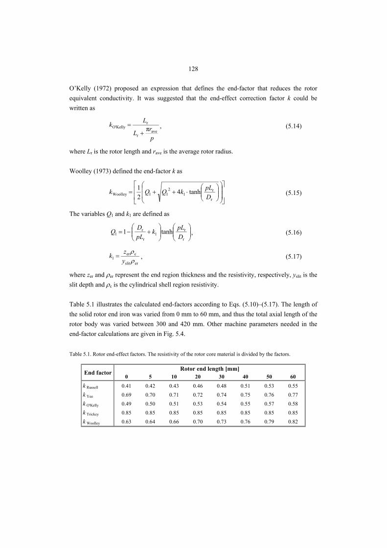
128
O’Kelly (1972) proposed an expression that defines the end-factor that reduces the rotor equivalent conductivity. It was suggested that the end-effect correction factor k could be written as
prL
Lkave
r
rKellyO' π
+= , (5.14)
where Lr is the rotor length and rave is the average rotor radius. Woolley (1973) defined the end-factor k as
⎥⎥
⎦
⎤
⎢⎢
⎣
⎡
⎟⎟
⎠
⎞
⎜⎜
⎝
⎛⎟⎟⎠
⎞⎜⎜⎝
⎛⋅++=
r
r1
211Woolley tanh4
21
DpLkQQk (5.15)
The variables Q1 and k1 are defined as
⎟⎟⎠
⎞⎜⎜⎝
⎛⎟⎟⎠
⎞⎜⎜⎝
⎛+−=
r
r1
r
r1 tanh1
DpLk
pLDQ , (5.16)
erslit
cer1 ρ
ρyzk = , (5.17)
where zer and ρer represent the end region thickness and the resistivity, respectively, yslit is the slit depth and ρc is the cylindrical shell region resistivity. Table 5.1 illustrates the calculated end-factors according to Eqs. (5.10)–(5.17). The length of the solid rotor end iron was varied from 0 mm to 60 mm, and thus the total axial length of the rotor body was varied between 300 and 420 mm. Other machine parameters needed in the end-factor calculations are given in Fig. 5.4. Table 5.1. Rotor end-effect factors. The resistivity of the rotor core material is divided by the factors.
0 5 10 20 30 40 50 60
k Russell 0.41 0.42 0.43 0.46 0.48 0.51 0.53 0.55k Yee 0.69 0.70 0.71 0.72 0.74 0.75 0.76 0.77k O'Kelly 0.49 0.50 0.51 0.53 0.54 0.55 0.57 0.58k Trickey 0.85 0.85 0.85 0.85 0.85 0.85 0.85 0.85k Woolley 0.63 0.64 0.66 0.70 0.73 0.76 0.79 0.82
Rotor end length [mm]End factor
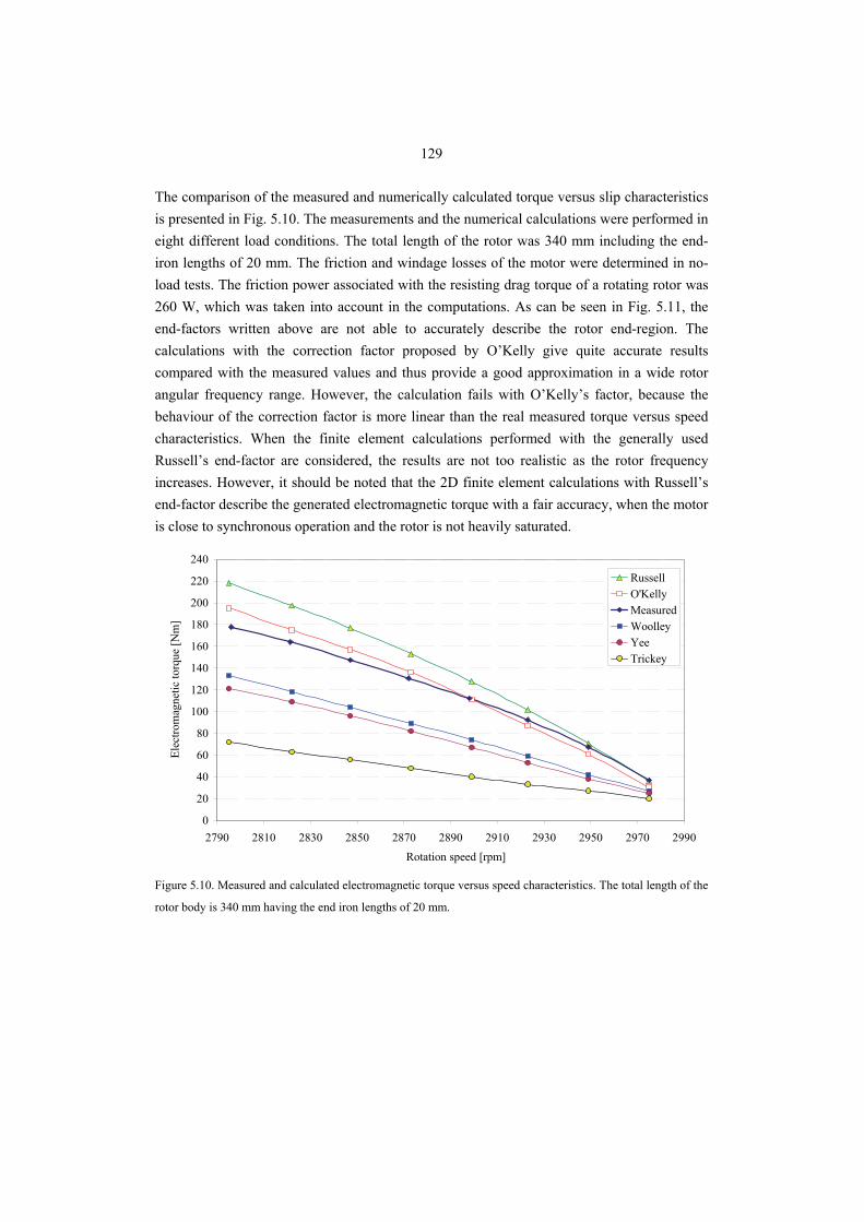
129
The comparison of the measured and numerically calculated torque versus slip characteristics is presented in Fig. 5.10. The measurements and the numerical calculations were performed in eight different load conditions. The total length of the rotor was 340 mm including the end-iron lengths of 20 mm. The friction and windage losses of the motor were determined in no-load tests. The friction power associated with the resisting drag torque of a rotating rotor was 260 W, which was taken into account in the computations. As can be seen in Fig. 5.11, the end-factors written above are not able to accurately describe the rotor end-region. The calculations with the correction factor proposed by O’Kelly give quite accurate results compared with the measured values and thus provide a good approximation in a wide rotor angular frequency range. However, the calculation fails with O’Kelly’s factor, because the behaviour of the correction factor is more linear than the real measured torque versus speed characteristics. When the finite element calculations performed with the generally used Russell’s end-factor are considered, the results are not too realistic as the rotor frequency increases. However, it should be noted that the 2D finite element calculations with Russell’s end-factor describe the generated electromagnetic torque with a fair accuracy, when the motor is close to synchronous operation and the rotor is not heavily saturated.
0
20
40
60
80
100
120
140
160
180
200
220
240
2790 2810 2830 2850 2870 2890 2910 2930 2950 2970 2990
Rotation speed [rpm]
Elec
trom
agne
tic to
rque
[Nm
]
RussellO'KellyMeasuredWoolleyYeeTrickey
Figure 5.10. Measured and calculated electromagnetic torque versus speed characteristics. The total length of the
rotor body is 340 mm having the end iron lengths of 20 mm.
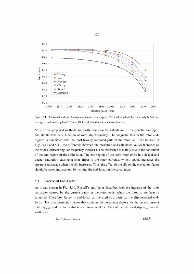
130
0.30
0.35
0.40
0.45
0.50
0.55
0.60
0.65
0.70
0.75
2790 2810 2830 2850 2870 2890 2910 2930 2950 2970 2990Rotation speed [rpm]
Pow
er fa
ctor
TrickeyYeeWoolleyO'KellyRussellMeasured
Figure 5.11. Measured and calculated power factors versus speed. The total length of the rotor body is 340 mm
having the end iron lengths of 20 mm. All the calculated results are too optimistic.
Most of the proposed methods are partly based on the calculation of the penetration depth, and should thus be a function of rotor slip frequency. The magnetic flux in the rotor end-regions is associated with the most heavily saturated parts of the rotor. As it can be seen in Figs. 5.10 and 5.11, the difference between the measured and calculated values increases as the rotor electrical angular frequency increases. The difference is mainly due to the saturation of the end region of the solid rotor. The end region of the solid rotor drifts in a deeper and deeper saturation causing a skin effect to the rotor currents, which, again, increases the apparent resistance when the slip increases. Thus, the effect of the slip on the correction factor should be taken into account by varying the end-factor in the calculation.
5.3 Corrected End-Factor
As it was shown in Fig. 5.10, Russell’s end-factor describes well the increase of the rotor resistivity caused by the current paths in the rotor ends, when the rotor is not heavily saturated. Therefore, Russell’s end-factor can be used as a basis for the slip-corrected end-factor. The total correction factor that contains the correction factors for the curved current paths kRussell, and the factor that takes into account the effect of the increased slip kAho, may be written as
AhoRusselltot kkk ⋅= . (5.18)
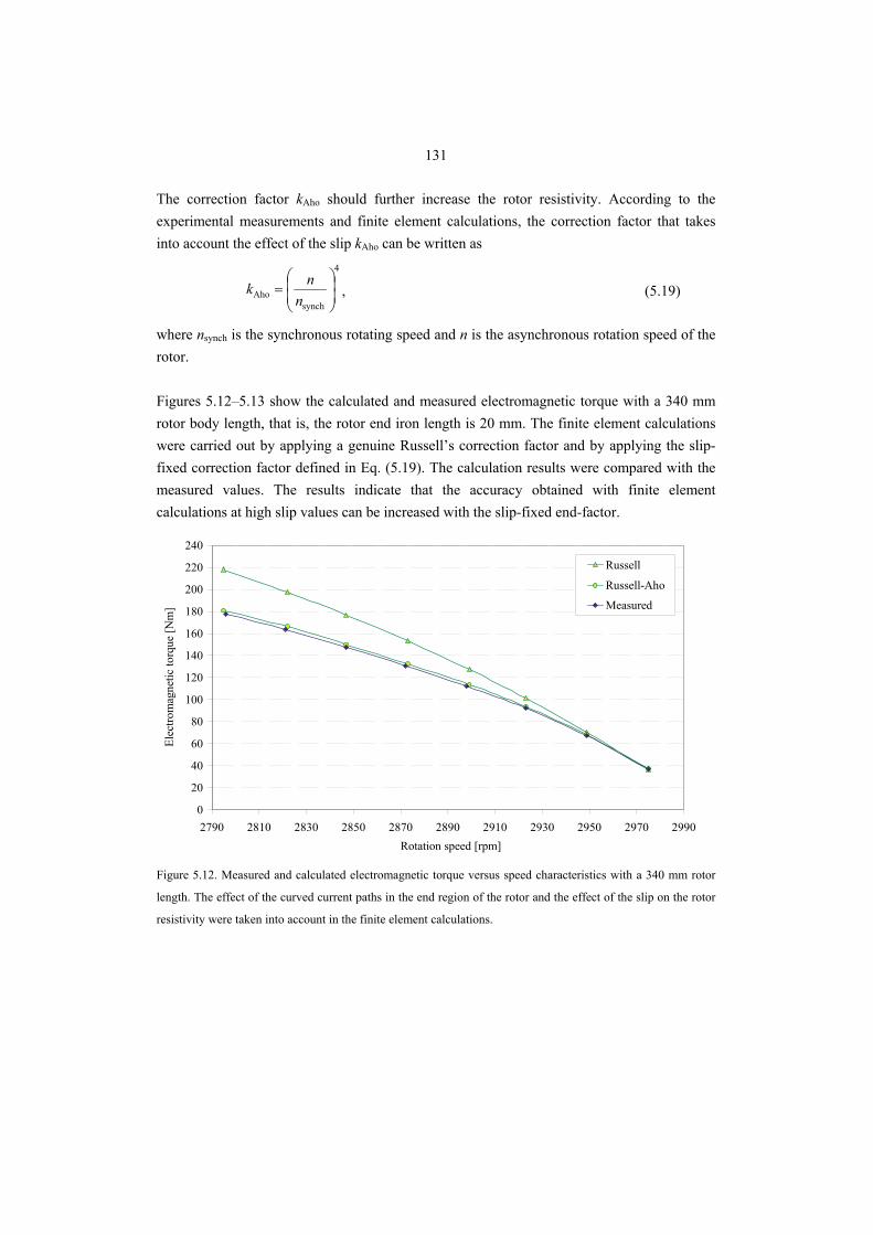
131
The correction factor kAho should further increase the rotor resistivity. According to the experimental measurements and finite element calculations, the correction factor that takes into account the effect of the slip kAho can be written as
4
synchAho ⎟
⎟⎠
⎞⎜⎜⎝
⎛=
nnk , (5.19)
where nsynch is the synchronous rotating speed and n is the asynchronous rotation speed of the rotor. Figures 5.12–5.13 show the calculated and measured electromagnetic torque with a 340 mm rotor body length, that is, the rotor end iron length is 20 mm. The finite element calculations were carried out by applying a genuine Russell’s correction factor and by applying the slip-fixed correction factor defined in Eq. (5.19). The calculation results were compared with the measured values. The results indicate that the accuracy obtained with finite element calculations at high slip values can be increased with the slip-fixed end-factor.
0
20
40
60
80
100
120
140
160
180
200
220
240
2790 2810 2830 2850 2870 2890 2910 2930 2950 2970 2990Rotation speed [rpm]
Elec
trom
agne
tic to
rque
[Nm
]
Russell
Russell-Aho
Measured
Figure 5.12. Measured and calculated electromagnetic torque versus speed characteristics with a 340 mm rotor
length. The effect of the curved current paths in the end region of the rotor and the effect of the slip on the rotor
resistivity were taken into account in the finite element calculations.
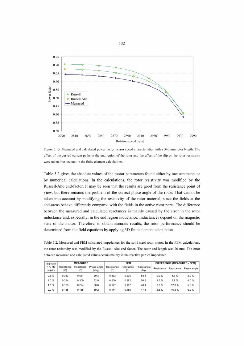
132
0.30
0.35
0.40
0.45
0.50
0.55
0.60
0.65
0.70
0.75
2790 2810 2830 2850 2870 2890 2910 2930 2950 2970 2990Rotation speed [rpm]
Pow
er fa
ctor
RussellRussell-AhoMeasured
Figure 5.13. Measured and calculated power factor versus speed characteristics with a 340 mm rotor length. The
effect of the curved current paths in the end region of the rotor and the effect of the slip on the rotor resistivity
were taken into account in the finite element calculations. Table 5.2 gives the absolute values of the motor parameters found either by measurements or by numerical calculations. In the calculations, the rotor resistivity was modified by the Russell-Aho end-factor. It may be seen that the results are good from the resistance point of view, but there remains the problem of the correct phase angle of the rotor. That cannot be taken into account by modifying the resistivity of the rotor material, since the fields at the end-areas behave differently compared with the fields in the active rotor parts. The difference between the measured and calculated reactances is mainly caused by the error in the rotor inductance and, especially, in the end region inductance. Inductances depend on the magnetic state of the motor. Therefore, to obtain accurate results, the rotor performance should be determined from the field equations by applying 3D finite element calculation. Table 5.2. Measured and FEM-calculated impedances for the solid steel rotor motor. In the FEM calculations,
the rotor resistivity was modified by the Russell-Aho end factor. The rotor end length was 20 mm. The error
between measured and calculated values occurs mainly in the reactive part of impedance.
Resistance [Ω]
Reactance [Ω]
Phase angle [deg]
Resistance [Ω]
Reactance [Ω]
Phase angle [deg] Resistance Reactance Phase angle
0.5 % 0.333 0.561 59.3 0.333 0.535 58.1 0.0 % 4.6 % 2.0 %
1.0 % 0.234 0.309 52.9 0.230 0.282 50.8 1.5 % 8.7 % 4.0 %
1.5 % 0.183 0.224 50.8 0.177 0.197 48.1 3.3 % 12.0 % 5.3 %
2.0 % 0.155 0.185 50.2 0.144 0.155 47.1 6.6 % 16.3 % 6.2 %
Slip with 170 Hz supply
MEASURED DIFFERENCE (MEASURED - FEM)FEM
133
The theoretical justification of the behaviour of magnetic fields in the rotor would require a 3D nonlinear eddy-current analysis. Some analytic estimations using Agarwal's theory might be made. The resistive part of the rotor in 2D calculations is corrected by increasing the rotor material resistivity in the calculations, as was done above. This, however, neglects the rotor end leakage inductance. The rotor end leakage may be estimated roughly by using Agarwal's non-limiting theory. The rectangular approximation to the BH curve is good only at very high levels of magnetization. This analysis gives a constant value of 26.6° to the rotor impedance phase angle when the applied magnetizing force is assumed to be sinusoidally distributed (MacLean 1954, Chalmers 1972, Yee 1972). We assume that the ferromagnetic end ring is heavily saturated and produces an inductance corresponding to the phase angle of 26.6°. The effect of the length of the rotor end area on the accuracy of 2D finite element calculation is shown in Figs. 5.14 and 5.15. The electrical angular frequencies of the rotor currents were 10.6 rad/s, 16.0 rad/s or 21.5 rad/s (i.e., the per unit slips with 170 Hz supply are 0.01, 0.015 and 0.02, respectively). It can be seen that the 2D calculations with the proposed corrected Russell’s factor show a quite high accuracy when the slip is large. The calculations follow well the measured values, if the rotor end length exceeds Agarwal’s penetration depth. We calculate Agarwal's penetration depth by using the saturation flux density of 2 T and a corresponding saturation field strength of 10000 A/m for Fe52 (Pyrhönen 1991) at 0.01 slip corresponding to a 10.6 1/s angular frequency.
m 016.02107.36.10
100002ˆ26
sr
0Agarwal =
⋅⋅⋅⋅
==Bω
Hδσ
(5.20)
Based on this result, we may say that the suitable end ring length of the motor at its rated operation point is about 15 mm. Figures 5.14 and 5.15 show the correlation of calculated and measured torque at three operation points. In the FEM calculations, the rotor end-effects were taken into account by modifying the rotor resistance by the end-factor: the end-factor based on the work by Russell is shown in Eq. (5.10) and the definition of the modified Russell’s end-factor, Russell-Aho, is shown in Eq. (5.18). In Fig. 5.14, it should be noted that some end correction factor should be applied even when the rotor is as long as the active stator stack and there are no ferromagnetic end rings.
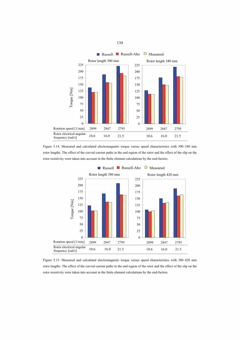
134
Torq
ue [N
m]
Rotation speed [1/min]Rotor electrical angular frequency [rad/s] 21.516.010.621.516.010.6
Rotor length 300 mm Rotor length 340 mm
MeasuredRussell-AhoRussell
0
25
50
75
100
125
150
175
200
225
2899 2847 27950
25
50
75
100
125
150
175
200
225
2899 2847 2795
Figure 5.14. Measured and calculated electromagnetic torque versus speed characteristics with 300–340 mm
rotor lengths. The effect of the curved current paths in the end region of the rotor and the effect of the slip on the
rotor resistivity were taken into account in the finite element calculations by the end-factors.
Rotation speed [1/min]Rotor electrical angular frequency [rad/s] 21.516.010.621.516.010.6
Torq
ue [N
m]
Rotor length 380 mm Rotor length 420 mm
MeasuredRussell-AhoRussell
0
25
50
75
100
125
150
175
200
225
2899 2847 27950
25
50
75
100
125
150
175
200
225
2899 2847 2795
Figure 5.15. Measured and calculated electromagnetic torque versus speed characteristics with 380–420 mm
rotor lengths. The effect of the curved current paths in the end region of the rotor and the effect of the slip on the
rotor resistivity were taken into account in the finite element calculations by the end-factors.
135
In Figures 5.14–5.15, we see that the torque calculation is satisfactorily correct when Russell's corrected end-effect factor is used. However, in Fig 5.13 we may see that the machine power factor is still too optimistic when this resistivity correction is used. We now adopt a new approach and assume that the power factor may be corrected by using Agarwal's inductance at the rotor end. This is done in the following example. EXAMPLE: We correct the rotor resistivity by the Russell factor for a 20 mm long end area
46.02π
tanhπ2
1p
r
r
pRussell =⎟
⎟⎠
⎞⎜⎜⎝
⎛−=
ττ LL
k .
We also calculate kAho at n = 2898 at 50 Hz supply (i.e. slip is 1 % at 170 Hz supply)
87.04
synchAho =⎟
⎟⎠
⎞⎜⎜⎝
⎛=
nnk .
40.087.046.0AhoRussellAho-Russell =⋅== kkk .
50.240.011
AhoRussell==
−k.
The end leakage field effect is, hence, 1.50 times the active part effect. The end corresponds to about 1.50/2.50 = 0.60 of the rotor total resistivity. The rotor end leakage reactance when the rotor ends are totally saturated is
( ) 30.0j6.26tan60.0jer =°⋅=X
We now take the rotor per unit impedance from the 2D FEM calculation result which is Zr = 1∠22.6°. This is a natural result since the rotor core is slitted and Agarwal’s 26.6° is valid for a smooth surface. When we add the reactive part of Agarwal's impedance j0.30 to rotor’s active part impedance 1∠22.6° = 0.92 + j0.38 we get the rotor total impedance
( ) °∠=+=++= 3614.1.680j92.030.038.0j92.0rZ .
The measured rotor impedance at 1 % slip with 20 mm ends is 1.16∠36°. We may, hence, conclude that the addition of Agarwal's inductance in a correct proportion to the rotor impedance gives a very good agreement with the measured values. The motor power factor after the addition of Agarwal's inductance is shown in Fig. 5.16.
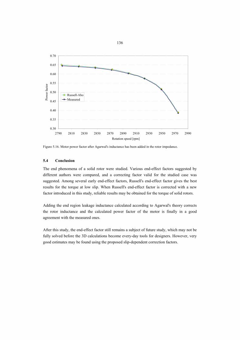
136
0.30
0.35
0.40
0.45
0.50
0.55
0.60
0.65
0.70
2790 2810 2830 2850 2870 2890 2910 2930 2950 2970 2990Rotation speed [rpm]
Pow
er fa
ctor
Russell-AhoMeasured
Figure 5.16. Motor power factor after Agarwal's inductance has been added in the rotor impedance.
5.4 Conclusion
The end phenomena of a solid rotor were studied. Various end-effect factors suggested by different authors were compared, and a correcting factor valid for the studied case was suggested. Among several early end-effect factors, Russell's end-effect factor gives the best results for the torque at low slip. When Russell's end-effect factor is corrected with a new factor introduced in this study, reliable results may be obtained for the torque of solid rotors. Adding the end region leakage inductance calculated according to Agarwal's theory corrects the rotor inductance and the calculated power factor of the motor is finally in a good agreement with the measured ones. After this study, the end-effect factor still remains a subject of future study, which may not be fully solved before the 3D calculations become every-day tools for designers. However, very good estimates may be found using the proposed slip-dependent correction factors.
137
6. CONCLUSIONS
A comprehensive analysis of solid-rotor induction machines is presented in the thesis. However, the state-of-the-art computational power is still limited today, and therefore, most of the analyses were performed by two-dimensional calculations, and the real three-dimensional end-effects were mainly studied by experiments. All the main characteristics of the solid rotor were studied; the results of these studies may be regarded as the main contributions of this dissertation: Ferromagnetic solid rotor material The optimization of the solid rotor material is a very complicated process; the main guidelines may be found in Chapter 2, but are repeated here for the convenience of the reader:
Resistivity of the ferromagnetic solid rotor material should be as low as possible to produce torque at a low slip. The lower the resistivity of the rotor core material the lower are the rotor slip-dependent losses and the more efficiently the motor is operating. The rotor surface losses caused by the air gap harmonics increase while the resistivity of the rotor material decreases. However, the conductivity of the ferromagnetic material alloys does not reach the values at which the surface losses increase to a harmful level.
Saturation flux density of the rotor core material in the case of a smooth rotor should be about 1 T to ensure the flux penetration deep into the rotor core. For a slitted solid rotor, the saturation flux density can be higher. The practical values for a slitted rotor construction are between 1 T and 2 T.
Initial relative permeability of the ferromagnetic rotor core material at the origin of the BH curve is rather insignificant. If the saturation flux density of the smooth rotor core material is about 1 T, the practical lower limit for the initial relative permeability is about 250. If the saturation flux density of the smooth rotor core material is higher, the initial relative permeability has to be decreased to obtain a proper penetration depth of the magnetic flux. In the case of a slitted rotor, the initial relative permeability should be above 250.
138
Axial rotor slitting In addition to the rotor material optimization, also the optimization of the solid rotor slitting strategy is a very complicated process, and it should be studied case by case. The rotor slitting designs were studied in Chapter 3. Below, the main contributions of the study associated with the rotor slitting are presented:
Rotor slit depth should be approximately half of the rotor radius. A suitable number of rotor slits of a correct depth produce the best efficiency and the best power factor for a solid rotor. In the cases studied, the best electromechanical performance at the rated torque was achieved when the rotor slit number was 34 and the slits were of an even depth of about 60 % of the rotor radius. The rotor mechanical strength, however, limits the practical slit depth to about 40–50 % of the rotor radius.
The rotor construction, where every other rotor slit is deeper than the other is mechanically vulnerable and it is therefore not recommended for the medium-speed solid rotor applications.
Odd numbers of rotor slits produce a significant unbalanced magnetic pull at a high frequency. The unbalanced magnetic pull is at least 20 times larger with odd slit numbers compared with even rotor slit numbers. Although the unbalanced net force does not exceed the weight of the rotor, the force is yet quite large. Therefore, the use of odd rotor slit number should be carefully considered. The torque ripple and the rotor losses of odd-slit-number rotors are lower than those of even-slit-number rotors.
Coating of a slitted solid rotor Coating of a solid rotor with a suitable ferromagnetic material may considerably improve the performance of a solid-rotor induction motor. However, the material properties and the thickness of the coating material must be selected with care. Below, the main observations found in Chapter 4 are given.
A uniform ferromagnetic coating cylinder surrounding the rotor core improves the medium-speed rotor performance at high rotational speeds. The ferromagnetic cylinder can be attached tightly on the rotor core material, thus improving the mechanical properties of the slitted solid rotor. In addition, a solid coating layer makes the rotor surface smooth, thus reducing the gas friction losses. A smooth surface, however, needs an effective cooling system. Rotors operating in ambient air pressure may be better cooled by using open rotor slits.
139
When the total loss in terms of output power is considered, the effect of the high resistivity coating material on the electrical efficiency of the machine is significant. The reduction of the air gap harmonic fields penetrating into rotor core material decreases the rotor losses and increases the total efficiency of the motor. Although the slip-dependent losses of the rotor slightly increase when the rotor is coated with a high-resistive ferromagnetic material, the total rotor losses with the coating material Sandvik 1080SM can be reduced by 15 %, and approximately a 1.0 % improvement in the electrical efficiency of the motor can be achieved. If higher resistivity materials were available, the improvement would even be greater.
Solid rotor end-effects When the rotor is made of a single piece of ferromagnetic material without electrically high-conductive end-rings, the rotor end fields have a significant effect on the motor characteristics. The length of the rotor ends should be approximately equal to the Agarwal’s penetration depth. If the rotor end region is longer, the apparent resistivity of the rotor is increased and the performance gets worse. If the rotor end is too short, it will saturate and the active torque producing rotor length becomes shorter, hence, reducing the torque output.
Veracity of performed FEM calculations The performance of the solid steel rotor induction machine can be determined through the FE calculations with tolerable accuracy. Although the calculation of a solid rotor is a pure three-dimensional eddy-current problem, the performance of the rotor can be estimated quite well using 2D tools. However, an end-factor, which considers the curves current paths in the rotor ends, is needed. This is because the rotor ends form a significant fraction of the total rotor impedance. Otherwise, the rotor impedance and the phase angle will be too small and the output power of the motor will be too optimistic.
Corrected end-factor Several corrective end-factors to describe the behaviour of the curved current paths in the rotor ends have been proposed in the literature. However, most of the proposed correction factors, which are dependent on the geometry of the rotor, are unsuccessful, because they do not depend on the electric angular rotor frequency. The performance of a ferromagnetic solid steel rotor, and especially the rotor ends, is very sensitive to changes in the rotor frequency. Therefore, a slip-dependent correction factor, which estimates the magnetic state of the rotor, is required to increase the calculation accuracy at high values of slip. The correction factor, proposed by Russell, can be
140
used as a base point for the corrective slip dependent end-factor, because it gives quite accurate results close to synchronous operation.
Veracity of proposed end-factor
The slip-dependent rotor correction factor, which is partly based on Russell’s end-factor, gives accurate results at a wide speed range. It should be noted that the slip-fixed end-factor, proposed in this thesis, is a fitting between measured and calculated values. Therefore, it cannot be guaranteed that it can be applied to different rotor geometries. Moreover, most probably, at very high slip values, the correction is too strong and the calculation loses its veracity. The accurate justification of the magnetic fields in the rotor ends would indisputably require a 3D nonlinear eddy-current analysis.
6.1 Future Work
Traditionally, the analysis of the rotating electric machines has been performed by analytical means. However, the effects of the stator and the rotor slotting, saturation of ferromagnetic materials and the movement of the rotor with respect to the stator are difficult to model by analytical methods. Furthermore, the actual electromagnetic field problem in the case of a solid-rotor induction motor is a pure three-dimensional non-linear eddy-current problem, which is a very complicated one to be tackled with analytical equations. When the solid rotor is not equipped with electrically high-conductive end rings, the rotor end fields have a significant effect on the motor characteristics. In 2D numerical finite element calculations, the 3D rotor end-effects can be approximated in the 2D model by modifying the rotor effective resistivity by an end factor. This gives the torque with a proper accuracy, but indisputably fails in the calculation of the rotor phase angle. Therefore, the power factor obtained from the FEM calculations is too optimistic. To take into account the complex three-dimensional current distribution in the end regions of the rotor iron, a full three-dimensional finite element analysis is required. In addition, to accurately model the electromagnetic fields inside the motor, a time-stepping 3D FEM should be used. The use of the transient 3D FEM is not recommended, because the problem in which the vector potential is to be solved within the whole rotor volume substantially increases the number of unknown variables, thus making the problem too demanding for the present-day personal computers.
141
The rotor materials play a major role in the improvement of the solid-rotor induction motor efficiency. The copper-iron alloy seems promising, but so far, it is not a readily commercially available material. The higher resistive ferromagnetic materials used as a coating cylinder for the slitted solid rotor also have potential to increase the motor efficiency. Further experimental measurements with different rotor core and coating materials are needed to complement and strengthen the picture of the optimal rotor design with different materials.
142
REFERENCES
Agarwal, P. D. (1959). Eddy-current losses in solid and laminated iron. AIEE trans. 78, 1959, pp. 169–181. Aglen, O. and Andersson, A. (2003). Thermal analysis of a high-speed generator. Proc. IEEE IAS annual meeting, vol. 1, 2003, pp. 547–554. Angst, G. (1962). Polyphase induction motor with solid rotor. Effects of saturation and finite length. AIEE Trans. P. III 81, 1962, pp. 902–909. Antila, M. (1998). Electromechanical properties of radial active magnetic bearings. Acta Polytechnica Scandinavica, Electrical Engineering Series no. 92. Dissertation, Helsinki University of Technology. Arkkio, A. (1987). Analysis of induction motors based on the numerical solution of the magnetic field and circuit equations. Acta Polytechnica Scandinavica, Electrical Engineering Series no. 59. Dissertation, Helsinki University of Technology. Arkkio, A. (1995). Unbalanced Magnetic Pull in a Four-Pole Induction Motor with an Odd Number of Rotor Slots, Proc. 2nd Chinese Int. Conf. Electrical Machines (CICEM), Hanzhou, China, 1995, pp. 343–348. Belmans, R., Verdyck, D., Geysen, W., Findlay, R. (1991). Electro-mechanical Analysis of the Audible Noise of an Inverter-Fed Squirrel-Cage Induction Motor. IEEE Transactions on Industry Applications, Vol. 27, No. 3, May/June 1991, pp. 539–544. Bergmann, D. (1982). Betriebseigenschaften von wärmeohrgekühlten Asynchron-Maschinen mit gerillten Massivrotor und Kurzschlusskäfig unter besonderer Berücksichtigung der Stromrichterspeisung. Dissertation, TH-Aachen. Bilgren, E., Boulos, R. (1973). Functional dependence of torque coefficient of coaxial cylinders on gap width and Reynolds numbers. Transactions on ASME, Journal of Fluids Engineering, series I, Vol. 95, 1973, pp. 122–126. Biro, O., K. Preis (1990). Finite Element Analysis of 3-D Eddy Currents. IEEE Transactions on Magnetics, Vol. 26, No. 2, March 1990, pp. 418–423. Bumby, J. R., Spooner, E., Jagiela, M. (2006). A Solid Rotor Induction Motor for Turbo-Assist Operation. XVII International Conference on Electrical Machines (ICEM) 2006, Chania, Greece. Cedrat, 2005. User’s guide of Flux2D™ (version 9.10) finite element program. Chalmers, B. J., Woolley, I. (1972). General theory of solid-rotor induction machines. Proc. IEE. Vol. 119, No. 9, 1972, pp. 1301–1308.
143
Coulomb, J. L. (1983). A methodology for the determination of global electromechanical quantities from a finite element analysis and its application to the evaluation of magnetic forces, torques and stiffness. IEEE Transactions on Magnetics, Vol. 19, pp. 1410–1413, (1983). Dorairaj, K. R., Krishnamurthy, M. R. (1967a). Polyphase Induction Machine with a Slitted Ferromagnetic Rotor: I – Experimental Investigations and a Novel Slipmeter. IEEE Trans. on Power Apparatus and Systems, vol. PAS-86, no. 7, July 1967, pp. 835–843. Dorairaj, K. R., Krishnamurthy, M. R. (1967b). Polyphase Induction Machine with a Slitted Ferromagnetic Rotor: II – Analysis. IEEE Transaction on Power Apparatus and Systems, Vol. PAS-86, No. 7, July 1967, pp. 844–855. Dorrell, D. G. (1993). Calculation of Unbalanced Magnetic Pull in Cage Induction Machines. Doctoral Thesis, University of Cambridge, Cambridge, United Kingdom, 1993. Ducreux J. P. and Nicolas, G. (1995). Finite length effects study in massive iron rotors using 3D electromagnetic field computation. IEEE Transactions on Power Apparatus and Systems Vol. 31, No. 3, 1995, pp. 2096–2099. Gieras, J. F. (1999). Comparison of High-Power High-Speed Machines: Cage-Induction versus Switched Reluctance Motors. Proc. of 5th Africon Conference 1999, Vol. 2, pp. 675–678. Gilon, D. C. (1991). Design and Testing of a 6 MW, 10 000 rpm Induction Motor. Proc. of 5th International Conference on Electrical Machines and Drives 1991, pp. 6–10. Heller, B. Hamata, V. (1977). Harmonic Field Effects in Induction Machines. Amsterdam: Elsevier. Heller, B. and Sarma, M. S. (1968). The Electromagnetic Field in Solid Iron. Acta. Tech. Prague. Huppunen, J. (2004). High-speed solid-rotor induction machine - Electromagnetic calculation and design. Acta Universitatis Lappeenrantaensis no. 197, Dissertation, Lappeenranta University of Technology. Ikeda, M., Sakabe, S., Higashi, K. (1990). Experimental study of high speed induction motor varying rotor core construction. IEEE Trans. on Energy Conversion. Vol. 5, No. 1, 1990, pp. 98–103. Jamieson, R.A. (1968). Eddy-current Effects in Solid, Unslotted Iron Rotors. Proc. IEE. Vol. 115, No. 6. pp. 813–820. Jamieson, R.A. (1968). Effects on Slots on Eddy Currents in Solid Iron Rotors. Proc. IEE. Vol. 115, No. 6. pp. 821–827. Jinning, L. and Fengli, F. (1987) Calculation of Magnetic Fields and Rotor Parameters for Induction Motor with Slitted Rotor. Proc. Electric Energy Conference. pp. 306–310.
144
Jokinen, T., Arkkio, A. (1996). High-Speed AC Machines. Proc. of Symposium on Power Electronics, Industrial Drives, Power Quality, Traction Systems (SPEEDAM) 1996. pp. B5-9–B5-14. Kanerva, S. (2005) Simulation of Electrical Machines, Circuits and Control Systems Using Finite Element Method and System Simulator. Dissertation, Helsinki University of Technology. Kim B.-T., Kwon, B-.I., Park, S.-C. (1999). Reduction of Electromagnetic Force Harmonics in Asynchronous Tractions Motor by Adapting the Rotor Slot Number. IEEE Transactions on Magnetics, Vol. 35, No. 5, September 1999, pp. 3742–3744. Kleiner, F., de Wit, B. and Ponick, B. (2001). Choosing electric turbo-compressor drives, IEEE Industry Applications Magazine, 2001, pp. 45–52. Kreith, F. (1968). Convection heat transfer in rotating systems. Advances in heat transfer, Vol. 5, Academic press Inc., USA. 1968, pp. 129–251. Kobayashi, T., Tajima, F., Ito, M., Shibukawa, S. (1997). Effects of Slot Combination on Acoustic Noise from Induction Motors. IEEE Transactions on Magnetics, Vol. 33, No. 2, March 1997, pp. 2101–2104. Kuosa, M. (2002). Numerical and experimental modelling of gas flow and heat transfer in the air gap of an electric machine. Acta Universitatis Lappeenrantaensis no. 129, Dissertation, Lappeenranta University of Technology. Lantto, E. Robust control of magnetic bearings in subcritical machines (1999). Acta Polytechnica Scandinavica, Electrical Engineering Series no. 94. Dissertation, Helsinki University of Technology, Espoo. Laporte B., Chabane, M., Sargos, F.M. (1994). Application of a Boundary Integral Method to the Optimization of Solid Rotor Machines. IEEE Transactions on Energy Conversion. Vol. 9, No. 3. pp. 604–612. Larjola, J., Sallinen, P., Lindgren, O., Esa, H., Pyrhönen, J., Lattu, J., Falck, R., (1991). Basic Research in High-Speed Technology. Research report EN B-71, Lappeenranta University of Technology, (in Finnish). Liese, M. (1977). Verfahren zur Berechnung von Wirbelströmen in Massiven Eisen. Archiv für Electrotechnik 59, pp. 75–85. Lindgren, O. and Väänänen, J. (1997). Plate Rotor Construction Used in the Rotor of an Asynchronous Electric Machine (WO/1997/002640). Publication International Application No. PCT/FI1996/000376. Lähteenmäki, J. (2002). Design and Voltage Supply of High-Speed Induction Machines. Dissertation, Acta Polytechnica Scandinavica, Electrical Engineering Series no. 108, Dissertation, Helsinki University of Technology.
145
Nau, S. L., and Mello, H.G.G (2000). Acoustic Noise in Induction Motors: Causes and Solutions. Proc. of Petroleum and Chemical Industry Conference 2000, 11–13. September, San Antonio, USA. pp. 253–263. Nechleba, F. (1940). Eindringen eines magnetischen Wechselfeldes in massives Eisen mit einer von der Feldstaerke abhaengigen Permeabilitaet. Archiv für Electrotechnik, Vol. 39. pp. 301–322. Maliti, K. C. (2000) Modelling and Analysis of Magnetic Noise in Squirrel-Cage Induction Motors. Doctoral Thesis, Royal Institute of Technology, Stockholm. McConnell, H. M. and Svedrup, E. F. (1955). The Induction Machine with Solid Iron Rotor. AIEE Transactions, Vol. 74, Part III (Power Apparatus and Systems), June 1955. Odegard, B., Stulz, A., Steimer, P. K. (1996). High-Speed, Variable Speed System in Megawatt Power Range. IEEE Industry Application Magazine, 1996. O’Kelly, D. (1972). Theory and Performance of Solid-Rotor Induction and Hysteresis Machines. Proc. IEE, Vol. 119, No. 9, September 1972, pp. 1301–1308. Oliver, J. A. and Samotyj, M. J. (1995). High-Speed, High-Horsepower Electric Motors For Pipeline Compressors: Available ASD Technology, Reliability, Harmonic Control. IEEE Transactions on Energy Conversion, Vol. 109, September 1995, pp. 470–476. Peesel, H. (1958). Über das Verhalten eines Asynchronmotors bei verschiedenen Läufern aus massive Stahl. Dissertation. Technische Hochschule Carolo-Wilhelmina zu Braunschweig. Pillai, K. P. (1969). Fundamental-frequency eddy-current loss due to rotating magnetic field. Part 1 – Eddy current loss in solid rotors. Proc. IEE, Vol. 116, No. 3, 1969, pp. 407–410. Pipes, L. A. (1956). Matrix theory of skin effect in laminations. J. of the Franklin Inst. 262, 1956, pp. 127–138. Pyrhönen, J., (1989). Massiiviroottorisen suurnopeusoikosulkumoottorin roottorimateriaalin vaikutus koneen ominaisuuksiin [Effects of the solid rotor core material on the high-speed induction machine characteristics]. Licentiate thesis, Lappeenranta University of Technology. (in Finnish) Pyrhönen, J., (1991). The high speed induction motor: Calculating the effects of solid rotor material on machine characteristics. Acta Polytechnica Scandinavica, Electrical Engineering Series, no. 68, Dissertation, Lappeenranta University of Technology. Pyrhönen, J. and, Kurronen, P. (1994). Massiiviroottorisen suurnopeusoikosulkumoottorin hyötysuhteen parantaminen, osa 3 [Increasing the efficiency of high-speed solid-rotor induction machine, part 3]. Research Report, EN B-19 Lappeenranta University of Technology. (in Finnish) Pyrhönen, J., Huppunen, J. (1996). A New Medium Speed Solid Rotor Induction Motor for a High Speed Milling Machine. Proc. of Symposium on Power Electronics, Industrial Drives, Power Quality, Traction Systems (SPEEDAM) 1996. pp. B5-1–B5-8.
146
Rajagopalan, P. K., Balarama Murty, V. (1969). Effects of axial slits on the performance of induction machines with solid rotors. IEEE Transaction on Power Apparatus and Systems 88, 1969, pp. 1695–1709. Rama, J. C., Gieseche, A. (1997). High-Speed Electric Drives: Technology and Opportunity. IEEE Industry Applications Magazine. Vol. 3, September/October, 1997, pp. 48–55. Richter, R. (1954). Elektrische Maschinen IV Die Induktionsmaschinen, Zweite verbesserte Auflage. Basel/Stuttgart, Verlag Birkhäuser. 1954. (in German). Riepe, F. (1981). Zweidimensionaler rechnergestützter Entwurf von Drehstrom-Asynkronmaschinen mit massiven Läufern. EtzArchiv 3 no. 3, 1981, pp. 71–75. Roberton, R. A., Harald Bornes, A. (1998). Adjustable-Frequency Drive Systems for North Gas Pipeline. IEEE Transactions on Industry Applications, Vol. 34, Issue 1, January-February 1998, pp. 187–195. Russell, R. L. and Norsworthy, K. H. (1958). Eddy Current and Wall Losses in Screened Rotor Induction Motors. Proc. IEE, Vol. 105A, No. 20, April 1958, pp. 163–173. Saari, J. (1998). Thermal analysis of high-speed induction machines. Acta Polytechnica Scandinavica, Electrical Engineering Series no. 90. Dissertation, Helsinki University of Technology, Espoo. Sarma M. S., Soni, G. R. Solid Rotor and Composite Rotor Induction Machines. IEEE Transaction on Aerospace and Electronic Systems, Vol. 8. No, 2, March 1972, pp. 147–155. Shah, M. R. and Lee, S. B. (2006). Rapid Analytical Optimization of Eddy-Current Shield Thickness for Associated Loss Minimization in Electrical Machines. IEEE Transaction on Industry Applications, Vol. 42, no. 3, May/June 2006, pp 642-649. Sharma, N. D. & al. (1996). Experimental investigations on high speed solid and composite rotor induction motor. Proceedings of the IEEE International Conference on Power Electronics, Drives & Energy Systems for Industrial Growth, PEDES, v 2, 1996, pp. 913–919. Silvester, P. P., Ferrari, R. L. (1990). Finite elements for electrical engineers. 2nd edition. Cambridge University Press, 1990. Szücs, A (2001). Macro Element Method for Modelling Eddy Currents in the Multi-conductor Windings of Electrical Machines. Acta Polytechnica Scandinavica, Electrical Engineering Series no. 106, Dissertation, Helsinki University of Technology. Tenhunen, A. (2003), Electromagnetic Forces Acting Between the Stator and Eccentric Cage Rotor. Dissertation, Report 69. Helsinki University of Technology. Trickey, P. H. (1936). Induction Motor Resistance Ring Width. Trans. Am. Inst. Elect. Eng. 55, 1936, pp. 144–150. United States Patent no: 5,473,211. Asynchronous Electric Machine and Rotor and Stator for Use in Association Therewith, (1995).
147
Vogt, K. (1996) Berechnung elektrischer Maschinen. VCH Verlagsgesellschaft mbH, Weinheim, 1996. Wiart, A (1982). New high-speed high-power machines with converter power supply. Motorcon September 1982, proceedings, pp. 354–365. Wilson, J. C. (1969). Theory of Solid Rotor Induction Machine. Dissertation, University of Colorado. Wood, A., Concordia, C. (1960a) An analysis of solid rotor machines: Part I, Operational impedance and equivalent circuits. AIEE Transactions on Power Apparatus and Systems, Vol. 78, 1960, pp. 1657-1665. Wood, A., Concordia, C. (1960b) An analysis of solid rotor machines: Part III, Finite length effects. AIEE Transactions on Power Apparatus and Systems, Vol. 79, 1960, pp. 21-26. Wood, A., Concordia, C. (1960c) An analysis of solid rotor machines: Part IV, An approximate nonlinear analysis. AIEE Transactions on Power Apparatus and Systems, Vol. 79, 1960, pp. 26-31. Wood, B. M., Olsen, C. L., HArtzo, G. D., Rama, J. C. Szenazi, F. R. (1997). Development of an 11 000 r/min 3500-hp induction motor and adjustable-speed drive for refinery service. IEEE Transactions on Industry Applications, Vol. 33, No. 3, 1997, pp. 815-825. Woolley, I., Chalmers, B. J. (1973). End-effects in Unlaminated Rotor Induction Machines. IEE Proc., Vol. 120, No. 6. pp. 641–646. Yamada, H. Calculation of torque characteristics of solid-rotor induction machines. Electrical Engineering in Japan, No. 2, 1970, pp. 1–9. Yee, H., Wilson, T. (1972). Saturation and Finite Length Effects in Solid-Rotor Induction Machines. Proc. IEE. Vol. 119, No. 7. pp. 877–882. Ylinen, A. (1970). Kimmo- ja lujuusoppi I-II, [Elasticity and strength of materials]. Porvoo: WSOY (in Finnish). Zaim, M. E. (1999). Non-linear Models for the Design of Solid Rotor Induction Machines. IEEE Transactions on Magnetics, Vol. 35, No. 3. pp. 1310–1313.
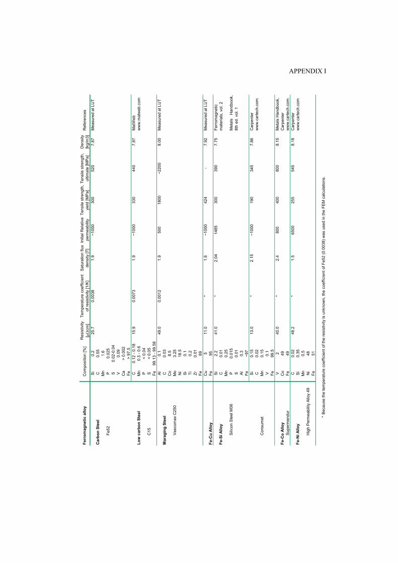
APPENDIX I
S
i0.
225
.70.
0038
1.9
~100
030
052
07.
87M
easu
red
at L
UT
Car
bon
Stee
lC
0.55
Mn
1.6
Fe52
P0.
025
S0.
02-0
.04
V0.
09C
a>
0.00
2Fe
> 97
.5C
0.12
- 0.
1815
.90.
0073
1.9
~100
033
044
07.
87M
atW
ebLo
w c
arbo
n St
eel
Mn
0.3
- 0.6
ww
w.m
atw
eb.c
omP
< 0.
04C
15S
< 0.
05Fe
99.1
3 - 9
9.58
Al
0.1
49.0
0.00
121.
950
018
00~2
200
8.00
Mea
sure
d at
LU
TM
arag
ing
Stee
lC
0.03
Co
8.5
Vas
com
ax C
250
Mo
3.25
Ni
18.5
Si
0.1
Ti0.
2Zr
0.01
Fe69
Cu
511
.0*
1.6
~100
042
4-
7.92
Mea
sure
d at
LU
TFe
-Cu
Allo
yFe
95S
i2.
2*
390
Fe-S
i Allo
yC
0.01
Mn
0.25
Sili
con
Ste
el M
36P
0.01
5S
0.01
Al
0.3
Fe~9
7S
i0.
1513
.0*
2.15
~100
019
034
57.
86C
arpe
nter
C0.
02w
ww
.car
tech
.com
Con
sum
etM
n0.
15V
0.1
Fe99
.5V
2*
800
Met
als
Han
dboo
k,
Fe-C
o Al
loy
Co
49C
arpe
nter
Supe
rmen
dur
Fe49
ww
w.c
arte
ch.c
omC
0.02
48.2
*1.
565
0025
554
58.
18C
arpe
nter
Fe-N
i Allo
yS
i0.
35w
ww
.car
tech
.com
Mn
0.5
Hig
h P
erm
eabi
lity
Allo
y 49
Ni
48Fe
51
*Be
caus
e th
e te
mpe
ratu
re c
oeffi
cien
t of t
he re
sist
ivity
is u
nkno
wn,
the
coef
ficie
nt o
f Fe5
2 (0
.003
8) w
as u
sed
in th
e FE
M c
alcu
latio
ns.
Ferr
omag
netic
allo
yC
ompo
sitio
n [%
]R
esis
tivity
[ μ
Ωcm
]S
atur
atio
n flu
x de
nsity
[T]
Initi
al R
elat
ive
perm
eabi
lity
Tens
ile s
treng
th,
yiel
d [M
Pa]
Tens
ile s
treng
th,
ultim
ate
[MP
a]D
ensi
ty
[kg/
m3]
300
7.75
Ferr
omag
netic
m
ater
ials
, vol
. 2
Met
als
Han
dboo
k,8t
h ed
. vol
. 1
Ref
eren
ces
41.0
2.04
8.15
40.0
2.4
800
400
1485
Tem
pera
ture
coe
ffici
ent
of re
sist
ivity
[1/K
]
ACTA UNIVERSITATIS LAPPEENRANTAENSIS
241. TENHUNEN, JARKKO. Johdon laskentatoimi kärkiyritysverkostoissa. Soveltamismahdollisuudet ja yritysten tarpeet. 2006. Diss.
242. KEMPPINEN, JUKKA. Digitaaliongelma. Kirjoitus oikeudesta ja ympäristöstä. 2006. 243. PÖLLÄNEN, KATI. Monitoring of crystallization processes by using infrared spectroscopy and
multivariate methods. 2006. Diss. 244. AARNIO, TEIJA. Challenges in packaging waste management: A case study in the fast food
industry. 2006. Diss. 245. PANAPANAAN, VIRGILIO M. Exploration of the social dimension of corporate responsibility in
a welfare state. 2006. Diss. 246. HEINOLA, JANNE-MATTI. Relative permittivity and loss tangent measurements of PWB
materials using ring resonator structures. 2006. Diss. 247. SALMELA, NINA. Washing and dewatering of different starches in pressure filters. 2006.
Diss. 248. SISSONEN, HELI. Information sharing in R&D collaboration – context-dependency and
means of governance. 2006. Diss. 249. PURANEN, JUSSI. Induction motor versus permanent magnet synchronous motor in motion
control applications: a comparative study. 2006. Diss. 250. PERÄLÄ, KARI. Kassanhallintakäytännöt Suomen kunnissa. 2006. Diss. 251. POUTIAINEN, ILKKA. A modified structural stress method for fatigue assessment of welded
structures. 2006. Diss. 252. LIHAVAINEN, VELI-MATTI. A novel approach for assessing the fatigue strength of ultrasonic
impact treated welded structures. 2006. Diss. 253. TANG, JIN. Computational analysis and optimization of real gas flow in small centrifugal
compressors. 2006. Diss. 254. VEHVILÄINEN, JUHA. Procurement in project implementation. 2006. Diss. 255. MIROLA, TUULI. Impacts of the European integration and the European Union membership
on Finnish export industries – Perceptions of export business managers. 2006. Diss. 256. RAUMA, KIMMO. FPGA-based control design for power electronic applications. 2006. Diss. 257. HIRVONEN, MARKUS. On the analysis and control of a linear synchronous servomotor with a
flexible load. 2006. Diss. 258. LIU, JUNHONG. On the differential evolution algorithm and its application to training radial
basis function networks. 2006. Diss. 259. LAITINEN, RISTO. Development of LC-MS and extraction methods for the analyses of AKD,
ASA, and rosin sizes in paper products. 2006. Diss. 260. KUISMA, PETRI. Seinärakenteen infrapunakontrastin pienentäminen käyttäen ilmajäähdytystä
ja säteilysuojausta. 2007. Diss. 261. ELLONEN, HANNA-KAISA. Exploring the strategic impact of technological change – studies
on the role of Internet in magazine publishing. 2007. Diss. 262. SOININEN, AURA. Patents in the information and communications technology sector –
development trends, problem areas and pressures for change. 2007. Diss.
263. MATTILA, MERITA. Value processing in organizations – individual perceptions in three case
companies. 2007. Diss. 264. VARTIAINEN, JARKKO. Measuring irregularities and surface defects from printed patterns.
2007. Diss. 265. VIRKKI-HATAKKA. TERHI. Novel tools for changing chemical engineering practice. 2007.
Diss. 266. SEKKI, ANTTI. Successful new venturing process implemented by the founding entrepreneur:
A case of Finnish sawmill industry. 2007. Diss. 267. TURKAMA, PETRA. Maximizing benefits in information technology outsourcing. 2007. Diss. 268. BUTYLINA, SVETLANA. Effect of physico-chemical conditions and operating parameters on
flux and retention of different components in ultrafiltration and nanofiltration fractionation of sweet whey. 2007. Diss.
269. YOUSEFI, HASSAN. On modelling, system identification and control of servo-systems with a
flexible load. 2007. Diss. 270. QU, HAIYAN. Towards desired crystalline product properties: In-situ monitoring of batch
crystallization. 2007. Diss. 271. JUSSILA, IIRO. Omistajuus asiakasomisteisissa osuuskunnissa. 2007. Diss. 272. 5th Workshop on Applications of Wireless Communications. Edited by Jouni Ikonen, Matti
Juutilainen and Jari Porras. 2007. 273. 11th NOLAMP Conference in Laser Processing of Materials Lappeenranta, August 20-22,
2007. Ed. by Veli Kujanpää and Antti Salminen. 2007. 274. 3rd JOIN Conference Lappeenranta, August 21-24, 2007. International Conference on Total
Welding Management in Industrial Applications. Ed. by Jukka Martikainen. 2007. 275. SOUKKA, RISTO. Applying the principles of life cycle assessment and costing in process
modeling to examine profit-making capability. 2007. Diss. 276. TAIPALE, OSSI. Observations on software testing practice. 2007. Diss. 277. SAKSA, JUHA-MATTI. Organisaatiokenttä vai paikallisyhteisö: OP-ryhmän strategiat
institutionaalisten ja kilpailullisten paineiden ristitulessa. 2007. Diss. 278. NEDEOGLO, NATALIA. Investigation of interaction between native and impurity defects in
ZnSe. 2007. Diss. 279. KÄRKKÄINEN, ANTTI. Dynamic simulations of rotors during drop on retainer bearings. 2007.
Diss. 280. KARPOVA, TATJANA. Aqueous photocatalytic oxidation of steroid estrogens. 2007. Diss. 281. SHIPILOVA, OLGA. Particle transport method for convection-diffusion-reaction problems.
2007. Diss. 282. ILONEN, JARMO. Supervised local image feature detection. 2007. Diss. 283. BOTAR-JID, CLAUDIU CRISTIAN. Selective catalytic reduction of nitrogen oxides with
ammonia in forced unsteady state reactors. Case based and mathematical model simulation reasoning. 2007. Diss.
284. KINNUNEN, JANNE. Direct-on-line axial flux permanent magnet synchronous generator static and dynamic performance. 2007. Diss.


![Diss Adriana Doria[1]](https://img.pdfslide.us/doc/110x75/55cf9b1e550346d033a4cf28/diss-adriana-doria1.jpg)