Embed Size (px)
Citation preview

Part No. 14175 - January 2007
DIS POS ER CONTROL CENTERInstallation Manual
Model CC-101K
www.insinkerator.com
Please be certain that the person who installs or uses this appliance carefully reads and understands the Safety Instructions contained in this manual.
The Danger signal indicates an immediately hazardous situation which, if not avoided, will result in death or serious injury.
The Warning signal alerts you to potential hazards or unsafe practices which, if not avoided, could result in severe personal injury or death.
The Caution signal alerts you to hazards of unsafe practices which, if not avoided, may result in minor personal injury or property damage.

2
Table of Contents
Introduction/Features Introduction ..................................................................................... 3 Features .......................................................................................... 3
Mounting The Control Center/Plumbing Connections Mounting the Control Center........................................................... 4 Plumbing Connections .................................................................... 4
Electrical Connections Diagrams ................................................................ 5
Electrical Connections .................................................................................. 6Operating Instructions .................................................................................. 7
Troubleshooting ............................................................................................. 8
Wiring Diagrams Model No. CC-101K-1 (120V, 1 phase, 1/2-2 HP) .......................... 9 Model No. CC-101K-2 (208-240V, 1 phase, 1/2-2 HP) ................. 10 Model No. CC-101K-3 (208-240V, 3 phase, 1/2-10 HP) ............... 11 Model No. CC-101K-4 (380-460V, 3 phase, 1/2-10 HP) ............... 12
Warranty
FOODSERVICE DISPOSER CONTROL CENTER LIMITED WARRANTY
InSinkErator Foodservice Disposer Control Centers are warranted against defects in material and workmanship for one year from the date of installation. The warranty includes parts and labor, provided the service is performed by an InSinkErator Factory Authorized Service Center. This warranty does not apply if failure is due to: faulty or improper electrical installation, faulty or improper plumbing installation, product abuse or misuse, or accidental damage.

3
Introduction/Features
PROPERTY DAMAGEUse of more than two solenoid valves will affect the overall function of the CC-101K control center. Extra solenoid valves will cause a reduction in voltage and solenoid actuation will not occur.
INTRODUCTIONThe CC-101K Control Center is UL® approved for use with InSinkErator Foodservice Disposers. See Table 1 for approved disposer and control center combinations. The control center operates the disposer. Its main functions are:
• To start and stop the disposer.
• To reverse the direction of the disposer motor automatically upon restart.
• To start the water fl ow to the disposer.
• To allow water fl ow for several minutes to fl ush the drain line after the disposer is turned off.
Model Waste Disposer Model
CC-101K-1CC-101K-2
SS50-26, SS75-27, SS100-28, SS125-25, SS150-34, SS150-38, SS200-27, SS200-31
CC-101K-3CC-101K-4
SS50-27, SS75-28, SS100-29, SS125-26, SS150-36, SS150-39, SS200-29, SS200-32, SS300-25, SS300-27, SS500-28, SS500-30, SS750-13,
SS750-15, SS1000-10, SS1000-12
Model Voltage Phase HP
CC-101K-1 120V 1 1/2-2
CC-101K-2 208-240V 1 1/2-2
CC-101K-3 208-240V 3 1/2-10
CC-101K-4 380-460V 3 1/2-10
FEATURESAUTOMATIC REVERSEThe disposer motor will reverse its direction of rotation automatically upon restart. To avoid motor damage, a fi ve second delay feature prevents reversing while the motor is coasting.
WATER SHUTOFF DELAY (POST FLUSH)After the motor is turned off, the water continues to fl ow for up to 10 minutes. The length of this post fl ush is controlled by the water shutoff delay timer. The post fl ush helps ensure that ground food waste is fl ushed out of the drain line. Adjust water shutoff delay as described in the operating instructions on page 7.
AUTOMATIC TIMED DISPOSER SHUTOFFThis water saving feature allows the disposer to run for up to 10 minutes before it automatically shuts off and must be manually restarted.
NOTE: This feature is set in the manual position at the factory. To activate the automatic timed disposer shutoff, disconnect the electric power to the control center, then open the control center door. Locate the shutoff plug at the top of the printed circuit board in the CC-101K (see Figure 8). Move the plug from manual (MAN) pins to automatic (AUTO) pins. The disposer now automatically shuts off 10 minutes after it starts.
EXTERNAL REMOTE CONTROLOne or more remote controls may be connected to the control center. These enable the operator to start or stop the disposer from any control station. A 24 V control circuit provides low voltage push button operation.
ELECTRIC DISCONNECT SWITCHThe lever switch on the front panel of the control center disconnects the line voltage. It interlocks with the front cover so that the cover cannot be opened unless the switch is in the off position.
NOTE: Use of the electrical disconnect switch results in a 30-second delay before system can be restarted. You must wait 30 seconds after reactivation of the line disconnect switch before system will start.
LOW VOLTAGE CONTROLControls operate on a 24 V solid state control circuit.
ENCLOSURENEMA 4 construction.
PUSH BUTTON OPERATIONPush Black button to start disposer.
Tabel 1. Approved Disposer and Control Center Combinations
Table 2. Electrical Specifi cations
4
Mounting the Control Center/Plumbing Connections
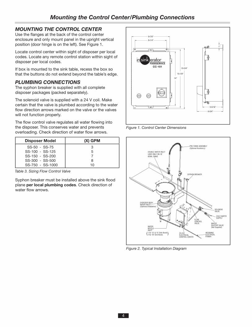
Figure 2. Typical Installation Diagram
MOUNTING THE CONTROL CENTERUse the fl anges at the back of the control center enclosure and only mount panel in the upright vertical position (door hinge is on the left). See Figure 1.
Locate control center within sight of disposer per local codes. Locate any remote control station within sight of disposer per local codes.
If box is mounted to the sink table, recess the box so that the buttons do not extend beyond the table’s edge.
PLUMBING CONNECTIONSThe syphon breaker is supplied with all complete disposer packages (packed separately).
The solenoid valve is supplied with a 24 V coil. Make certain that the valve is plumbed according to the water fl ow direction arrows marked on the valve or the valves will not function properly.
The fl ow control valve regulates all water fl owing into the disposer. This conserves water and prevents overloading. Check direction of water fl ow arrows.
Disposer Model (X) GPM
SS-50 - SS-75SS-100 - SS-125SS-150 - SS-200SS-300 - SS-500
SS-750 - SS-1000
357810
Syphon breaker must be installed above the sink fl ood plane per local plumbing codes. Check direction of water fl ow arrows.
Figure 1. Control Center Dimensions
Table 3. Sizing Flow Control Valve
5
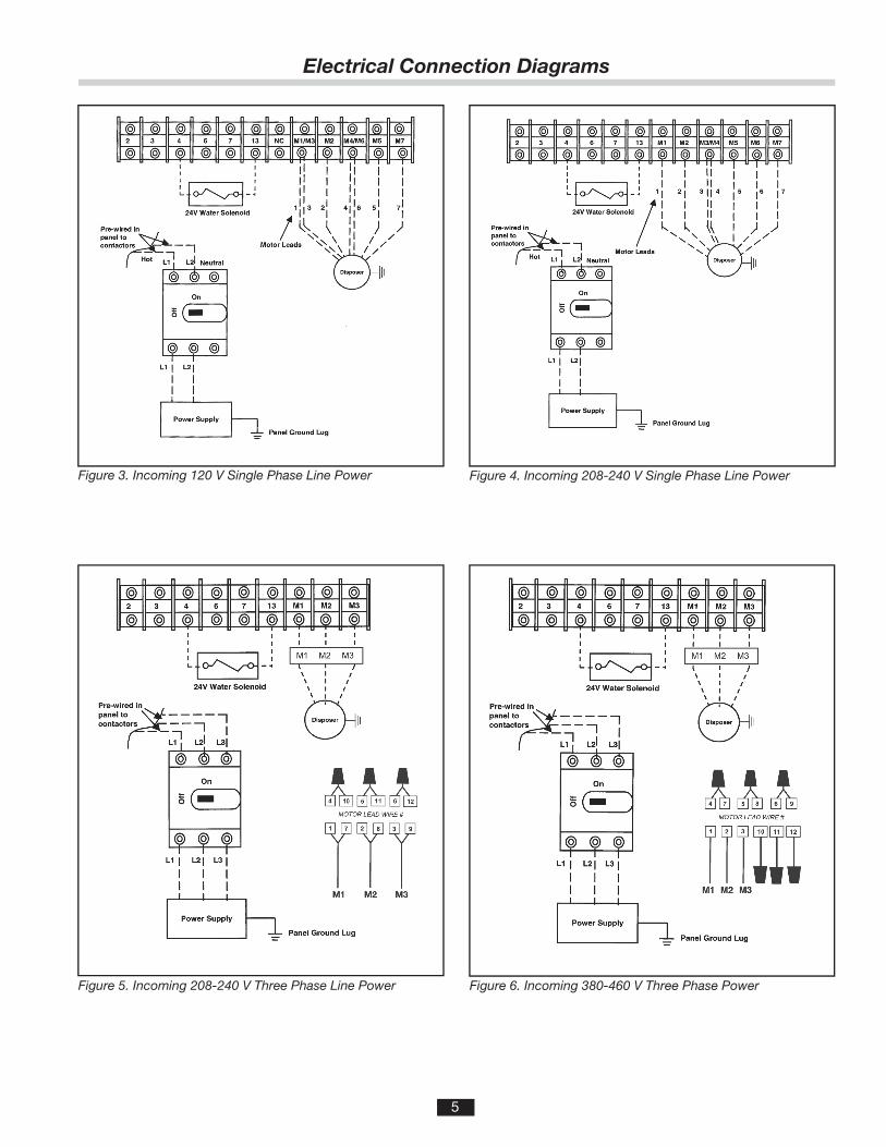
Figure 4. Incoming 208-240 V Single Phase Line PowerFigure 3. Incoming 120 V Single Phase Line Power
Figure 5. Incoming 208-240 V Three Phase Line Power Figure 6. Incoming 380-460 V Three Phase Power
Electrical Connection Diagrams
6
PERSONAL INJURY • Allow only trained personnel to operate disposer.
• Use baffl es and guarding to avoid splashing and ejection of materials.
• Do not put fi ngers or hands into the disposer.
• When attempting to remove objects from a disposer, use long-handled tongs or pliers.
• Turn power off before clearing a jam, removing an object from the disposer or pressing the red reset button. (See Troubleshooting).
• Disconnect electricity before adjusting set points.
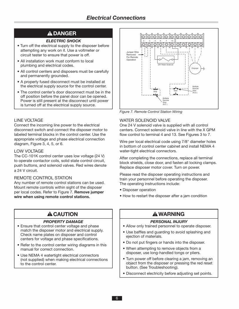
ELECTRIC SHOCK • Turn off the electrical supply to the disposer before attempting any work on it. Use a voltmeter or circuit tester to ensure that power is off.
• All installation work must conform to local plumbing and electrical codes.
• All control centers and disposers must be carefully and permanently grounded.
• A properly fused disconnect must be installed at the electrical supply source for the control center.
• The control center’s door disconnect must be in the off position before the panel door can be opened.Power is still present at the disconnect until power is turned off at the electrical supply source.
LINE VOLTAGEConnect the incoming line power to the electrical disconnect switch and connect the disposer motor to labeled terminal blocks in the control center. Use the appropriate voltage and phase electrical connection diagram, Figure 3, 4, 5, or 6.
LOW VOLTAGEThe CC-101K control center uses low voltage (24 V) to operate contactor coils, solid state control circuit, push buttons, and solenoid valves. Red wires denote a 24 V circuit.
REMOTE CONTROL STATIONAny number of remote control stations can be used. Mount remote controls within sight of the disposer per local codes. Refer to Figure 7. Remove jumper wire when using remote control stations.
Figure 7. Remote Control Station Wiring
WATER SOLENOID VALVEOne 24 V solenoid valve is supplied with all control centers. Connect solenoid valve in line with the X GPM fl ow control to terminal 4 and 13. See Figures 3 to 7.
Wire per local electrical code using 7/8" diameter holes in bottom of control center cabinet and install NEMA 4 water-tight electrical connectors.
After completing the connections, replace all terminal block shields, close door, and fasten all locking clamps. Replace disposer motor cover. Turn on power.
Please read the disposer operating instructions and train your personnel before operating the disposer. The operating instructions include:
• Disposer operation
• How to restart the disposer after a jam condition
PROPERTY DAMAGE • Ensure that control center voltage and phase
match the disposer motor and electrical supply. Check name plates on disposer and control centers for voltage and phase specifi cations.
• Refer to the control center wiring diagrams in this manual for correct connection.
• Use NEMA 4 watertight electrical connectors (not supplied) when making electrical connections to the control center.
Electrical Connections

7
OPERATING INSTRUCTIONSTO START1. Check to ensure disposer is free of foreign objects.
2. Ensure power is on.
3. Push start button. Disposer motor will run and water will fl ow into the disposer.
TO STOP1. Push stop button. Disposer motor and water will stop.
2. Water may continue to fl ow into disposer for up to 10 minutes, per the time set on the water shutoff delay timer.
NOTE: This post-fl ush clears the drain lines of food waste.
WATER SHUTOFF DELAY ADJUSTMENTThe water shutoff delay is adjustable from 30 secondsto 10 minutes.
Locate the water shutoff delay at the top of the printed circuit board in the CC-101K (See Figure 8). Set the dip switches for the desired water shut off delay. Use the guide printed on the circuit board to set minutes of delay. The dip switches should be moved to match the fi lled in areas of the guide.
Figure 8.
PERSONAL INJURYTo adjust the water shutoff delay, disconnect the electrical power to the control panel and open the control center door.
Example 1: Dip switches 1, 2, 3, 4 pushed to the down position will give a 0 minute delay.
Example 2: Dip switches 1, 3, 4 pushed to the up position; and dip switch 2 pushed to the down position will give a 10 minute delay.
AUTOMATIC TIMED DISPOSER SHUTOFFThis water saving feature allows the disposer to run for up to 10 minutes before it automatically shuts-off and must be manually restarted.
NOTE: This feature is set in the manual position at the factory. To activate the automatic timed disposer shut-off, disconnect the electric power to the control center, then open the control center door. Locate the Dip Switch Module at the top of the printed circuit board (see Figure 8). Move the #5 dip switch from MANUAL to AUTOMATIC. The disposer now automatically shuts off 10 minutes after it starts.
Operating Instructions

8
This control center was inspected and tested under operating conditions before shipment from the factory. In case of trouble, check the items listed below.
A. Disposer motor will not start and water does not fl ow.
1. No incoming line power, turn line power on.
2. Electric disconnect switch is not ON. Turn electric disconnect to ON position.
3. Electrical disconnect switch has been reactivated and 30-second delay has not yet expired. Wait 30 seconds and try starting again.
4. Control circuit fuse FNA2 is blown. Replace fuse.
B. Disposer motor stops while grinding but water continues to fl ow.
1. Control center wired for automatic shut-off. Repress start button. If disposer runs for 10 minutes then shuts off, the automatic shutoff is active. If the manual setting is desired, change as indicated in the feature section.
2. Disposer is jammed. Press the stop button and follow directions for unjamming that were supplied with the disposer.
3. Disposer motor overload protector has tripped. Follow instruction in C1.
C. Disposer will not start but water fl ows. 1. Overload protector on the disposer may have
tripped. Press stop button. Locate red reset button on front of disposer electrical cover. Press to reset. If motor had been running, wait fi ve minutes for the motor and overload to cool down before starting.
2. Disposer is jammed. Press the stop button and follow directions for unjamming that were supplied with the disposer.
PERSONAL INJURY • Allow only trained personnel to operate disposer.
• Use baffl es and guarding to avoid splashing and ejection of materials.
• Do not put fi ngers or hands into the disposer.
• When attempting to remove objects from a disposer, use long-handled tongs or pliers.
• Turn power off before clearing a jam, removing an object from the disposer or pressing the red reset button.
PROPERTY DAMAGEUse only an FNA2 replacement fuse. Using another replacement fuse will result in product damage.
ELECTRICAL SHOCK/PROPERTY DAMAGE • Troubleshooting other than what is recommended
in this section should only be performed by qualifi ed service personnel.
• Further troubleshooting performed by untrained personnel could result in electric shock or damage to the control center.
• All electrical checks must be performed by a qualifi ed professional.
Troubleshooting
D. Water fl ows constantly before start button is pushed
1. Water solenoid valve is installed backward. Water fl ow should be in the direction of the arrow on valve.
E. Overload trips frequently. 1. Do not overload disposer with excess amounts of
garbage and water. (See disposer instructions for recommended water fl ows.)

9
120 V1-phase
1/2 to 2 HP
CC-101K-1 Wiring Diagram
Call Toll Free 1-800-845-8345 for the nearest InSinkEratorAuthorized Service Agency or to reach Technical Support.
ELECTRICAL SHOCK • Turn off the electrical supply to the disposer before
attempting any work on it. Use a voltmeter or circuit tester to ensure that power is off.
• Installation must conform to local electrical codes.
• All control centers and disposers must be carefully and permanently grounded.
• A properly fused disconnect must be installed at the electrical supply source for the control center.
PROPERTY DAMAGE • Ensure that the control center voltage and phase
match the disposer motor and electrical supply. Check nameplates on disposers and control centers for voltage and phase specifi cation.
• The disposer motor wiring connection is shown in the disposer terminal box.
10
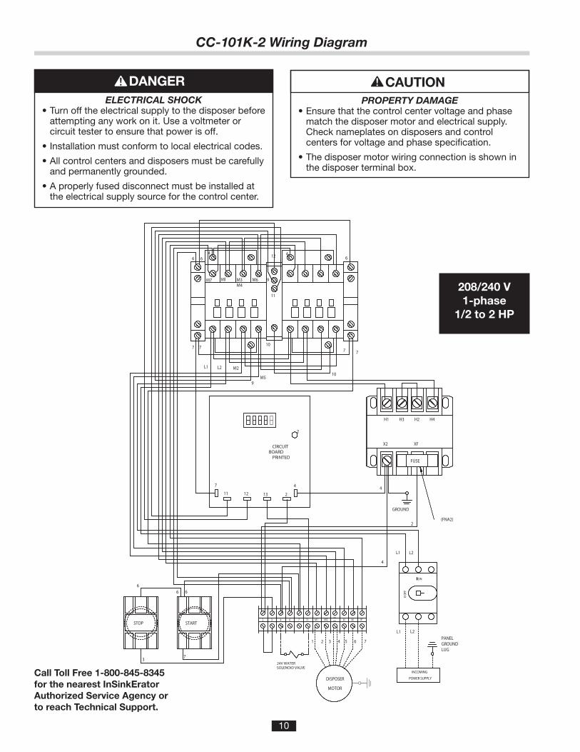
CC-101K-2 Wiring Diagram
208/240 V1-phase
1/2 to 2 HP
Call Toll Free 1-800-845-8345 for the nearest InSinkEratorAuthorized Service Agency or to reach Technical Support.
ELECTRICAL SHOCK • Turn off the electrical supply to the disposer before
attempting any work on it. Use a voltmeter or circuit tester to ensure that power is off.
• Installation must conform to local electrical codes.
• All control centers and disposers must be carefully and permanently grounded.
• A properly fused disconnect must be installed at the electrical supply source for the control center.
PROPERTY DAMAGE • Ensure that the control center voltage and phase
match the disposer motor and electrical supply. Check nameplates on disposers and control centers for voltage and phase specifi cation.
• The disposer motor wiring connection is shown in the disposer terminal box.

11
208/240 V3-phase
1/2 to 10 HP
CC-101K-3 Wiring Diagram
Call Toll Free 1-800-845-8345 for the nearest InSinkEratorAuthorized Service Agency or to reach Technical Support.
ELECTRICAL SHOCK • Turn off the electrical supply to the disposer before
attempting any work on it. Use a voltmeter or circuit tester to ensure that power is off.
• Installation must conform to local electrical codes.
• All control centers and disposers must be carefully and permanently grounded.
• A properly fused disconnect must be installed at the electrical supply source for the control center.
PROPERTY DAMAGE • Ensure that the control center voltage and phase
match the disposer motor and electrical supply. Check nameplates on disposers and control centers for voltage and phase specifi cation.
• The disposer motor wiring connection is shown in the disposer terminal box.

12
CC-101K-4 Wiring Diagram
380/460 V3-phase
1/2 to 10 HP
Call Toll Free 1-800-845-8345 for the nearest InSinkEratorAuthorized Service Agency or to reach Technical Support.
ELECTRICAL SHOCK • Turn off the electrical supply to the disposer before
attempting any work on it. Use a voltmeter or circuit tester to ensure that power is off.
• Installation must conform to local electrical codes.
• All control centers and disposers must be carefully and permanently grounded.
• A properly fused disconnect must be installed at the electrical supply source for the control center.
PROPERTY DAMAGE • Ensure that the control center voltage and phase
match the disposer motor and electrical supply. Check nameplates on disposers and control centers for voltage and phase specifi cation.
• The disposer motor wiring connection is shown in the disposer terminal box.