Embed Size (px)
Citation preview
Page 1 of 17
Permit Number: PRPSW Roll Number:
Required Information:
Signature of Applicant on Permit Applicant Declaration Disposal Field Design Considerations & Details - This form Completed.
Detailed System Schematics and Drawings - Attached
Wastewater Characteristics:Wastewater Peak Flow:
•• Fixture Unit Loads (please check all that apply):
Main Bathroom = 6 fixture units Ensuite with Shower = 6 fixture units
Site Evaluation Diagram - Appendix A - Attach a detailed site diagram including the system location in relation to buildings, distance to water supply and /or surface water bodies, and other pertinent information (as per Part 7 of the Private Sewage Standard of Practice 2009) .
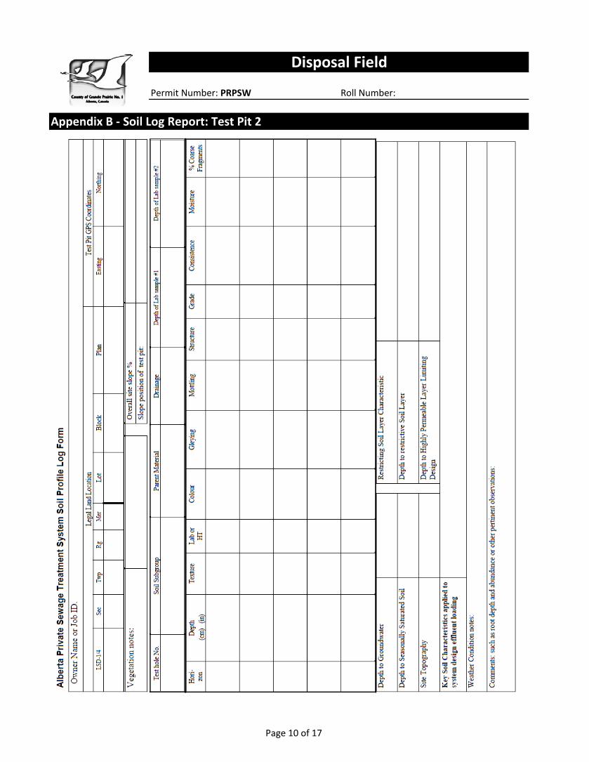
Soil Log Report from two (2) test pits with Soil Analysis Report - Appendix B - Completed.
Worksheets - Complete both 'Primary Effluent Treatment Field' - Appendix C and 'Pressure Distribution, Orifice, Pipe & Pump Sizing' - Appendix D
Specifications for System Components - Attached for Initial Treatment Component Design Details, including Septic Tank, Dose Tank, Effluent Pump.
Any other qualifications of limitations that in your opinion as the designer/installer are needed.
This private sewage system is for a (# of) bedroom single family dwelling. Total peak wastewater flow per day used in this design is imperial gallons. The average operating flow is expected to be gallons per day.
Disposal Field Design Considerations & Details
10001 - 84th Avenue, Clairmont, AB T0H 0W0Phone: 780.513.3950 Fax: 780.539.7686
The following information is to accompany the Private Sewage Disposal Permit Application for a Disposal Field.
Private Sewage Disposal Permit Application - Completed (please put N/A in spaces which are not applicable).
The sewage system includes a septic tank and disposal field. This system is suitable for the site and soil conditions of your property. The design reflected in the flowing applies, and meets the requirements of the current Alberta Private Sewage Systems Standards of Practice adopted under the Safety Codes Act to achieve effective treatment of the wastewater from this residence.
The development served is a (# of) bedroom single family dwelling.
Page 2 of 17
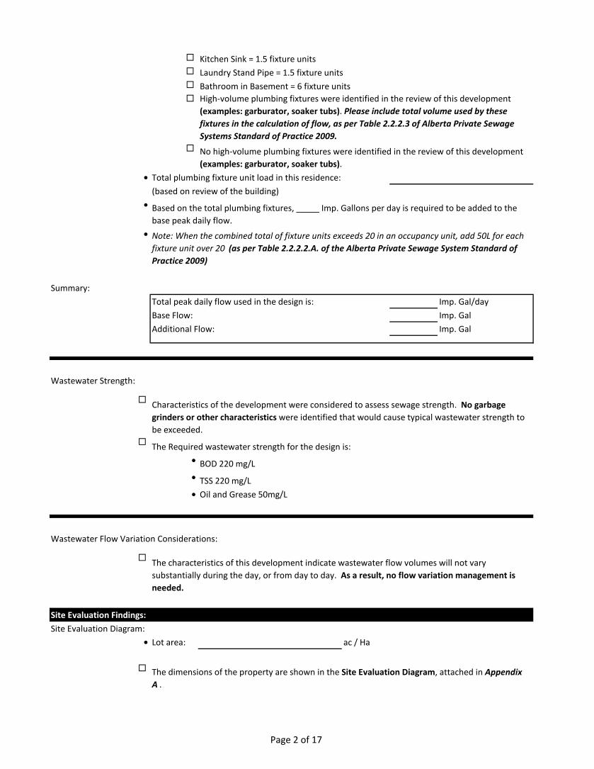
Kitchen Sink = 1.5 fixture units Laundry Stand Pipe = 1.5 fixture units Bathroom in Basement = 6 fixture units
• Total plumbing fixture unit load in this residence:(based on review of the building)
•
•
Total peak daily flow used in the design is: Imp. Gal/dayBase Flow: Imp. GalAdditional Flow: Imp. Gal
Wastewater Strength:
The Required wastewater strength for the design is:• BOD 220 mg/L• TSS 220 mg/L• Oil and Grease 50mg/L
Wastewater Flow Variation Considerations:
Site Evaluation Findings:Site Evaluation Diagram:
• Lot area: ac / Ha
Summary:
Characteristics of the development were considered to assess sewage strength. No garbage grinders or other characteristics were identified that would cause typical wastewater strength to be exceeded.
The characteristics of this development indicate wastewater flow volumes will not vary substantially during the day, or from day to day. As a result, no flow variation management is needed.
The dimensions of the property are shown in the Site Evaluation Diagram, attached in Appendix A .
High-volume plumbing fixtures were identified in the review of this development (examples: garburator, soaker tubs). Please include total volume used by these fixtures in the calculation of flow, as per Table 2.2.2.3 of Alberta Private Sewage Systems Standard of Practice 2009.
No high-volume plumbing fixtures were identified in the review of this development (examples: garburator, soaker tubs).
Based on the total plumbing fixtures, Imp. Gallons per day is required to be added to the base peak daily flow.
Note: When the combined total of fixture units exceeds 20 in an occupancy unit, add 50L for each fixture unit over 20 (as per Table 2.2.2.2.A. of the Alberta Private Sewage System Standard of Practice 2009)
Page 3 of 17
Soil Evaluation:
Restrictive Soil Conditions:•
•
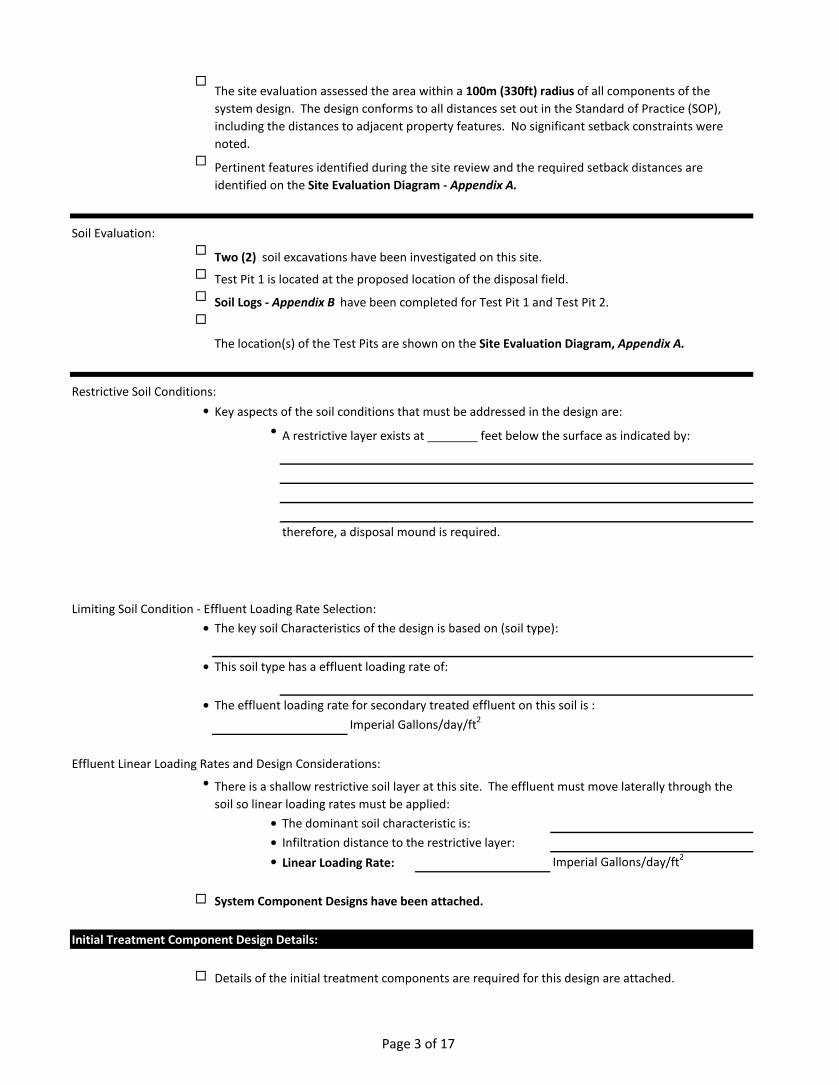
therefore, a disposal mound is required.
Limiting Soil Condition - Effluent Loading Rate Selection:•
• This soil type has a effluent loading rate of:
• The effluent loading rate for secondary treated effluent on this soil is :Imperial Gallons/day/ft2
Effluent Linear Loading Rates and Design Considerations:•
• The dominant soil characteristic is:• Infiltration distance to the restrictive layer:• Linear Loading Rate: Imperial Gallons/day/ft2
System Component Designs have been attached.
Initial Treatment Component Design Details:
The site evaluation assessed the area within a 100m (330ft) radius of all components of the system design. The design conforms to all distances set out in the Standard of Practice (SOP), including the distances to adjacent property features. No significant setback constraints were noted.
Pertinent features identified during the site review and the required setback distances are identified on the Site Evaluation Diagram - Appendix A.
The key soil Characteristics of the design is based on (soil type):
There is a shallow restrictive soil layer at this site. The effluent must move laterally through the soil so linear loading rates must be applied:
Details of the initial treatment components are required for this design are attached.
Two (2) soil excavations have been investigated on this site.
Test Pit 1 is located at the proposed location of the disposal field.
Soil Logs - Appendix B have been completed for Test Pit 1 and Test Pit 2.
The location(s) of the Test Pits are shown on the Site Evaluation Diagram, Appendix A.
Key aspects of the soil conditions that must be addressed in the design are:
A restrictive layer exists at feet below the surface as indicated by:
Page 4 of 17
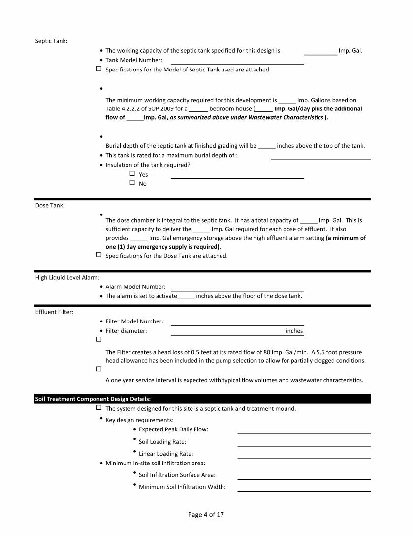
Septic Tank:• The working capacity of the septic tank specified for this design is Imp. Gal.• Tank Model Number: Specifications for the Model of Septic Tank used are attached.
•
•
• This tank is rated for a maximum burial depth of :• Insulation of the tank required?
Yes - No
Dose Tank:•
Specifications for the Dose Tank are attached.
High Liquid Level Alarm:• Alarm Model Number:• The alarm is set to activate inches above the floor of the dose tank.
Effluent Filter:• Filter Model Number:• Filter diameter: inches
Soil Treatment Component Design Details:
•
• Expected Peak Daily Flow:• Soil Loading Rate:• Linear Loading Rate:
•• Soil Infiltration Surface Area:• Minimum Soil Infiltration Width:
The minimum working capacity required for this development is Imp. Gallons based on Table 4.2.2.2 of SOP 2009 for a bedroom house ( Imp. Gal/day plus the additional flow of Imp. Gal, as summarized above under Wastewater Characteristics ).
Burial depth of the septic tank at finished grading will be inches above the top of the tank.
The dose chamber is integral to the septic tank. It has a total capacity of Imp. Gal. This is sufficient capacity to deliver the Imp. Gal required for each dose of effluent. It also provides Imp. Gal emergency storage above the high effluent alarm setting (a minimum of one (1) day emergency supply is required).
The Filter creates a head loss of 0.5 feet at its rated flow of 80 Imp. Gal/min. A 5.5 foot pressure head allowance has been included in the pump selection to allow for partially clogged conditions.
A one year service interval is expected with typical flow volumes and wastewater characteristics.
The system designed for this site is a septic tank and treatment mound.
Key design requirements:
Minimum in-site soil infiltration area:
Page 5 of 17
Effluent Distribution Design Detail:
Effluent Pressure Distribution:
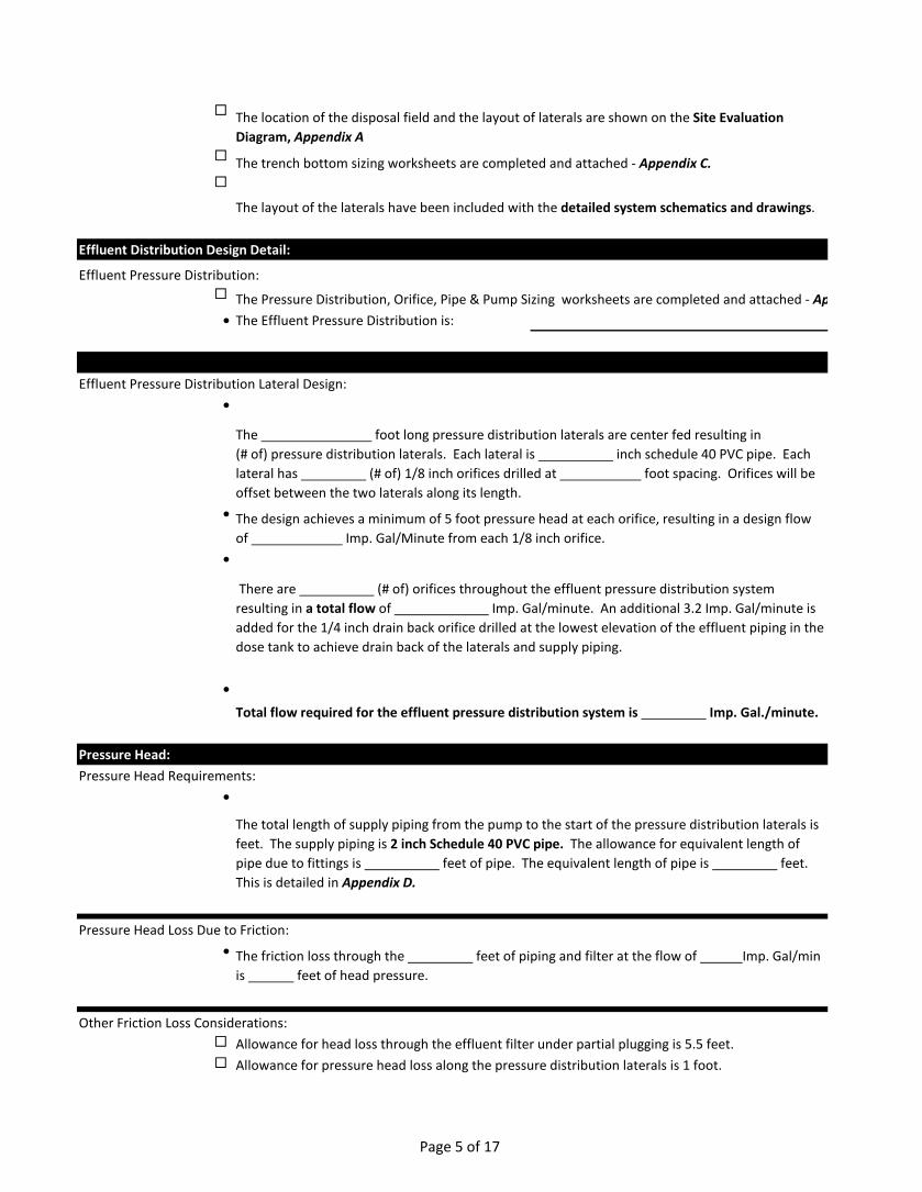
• The Effluent Pressure Distribution is:
Effluent Pressure Distribution Lateral Design:•
•
•
•
Pressure Head:Pressure Head Requirements:
•
Pressure Head Loss Due to Friction:•
Other Friction Loss Considerations: Allowance for head loss through the effluent filter under partial plugging is 5.5 feet. Allowance for pressure head loss along the pressure distribution laterals is 1 foot.
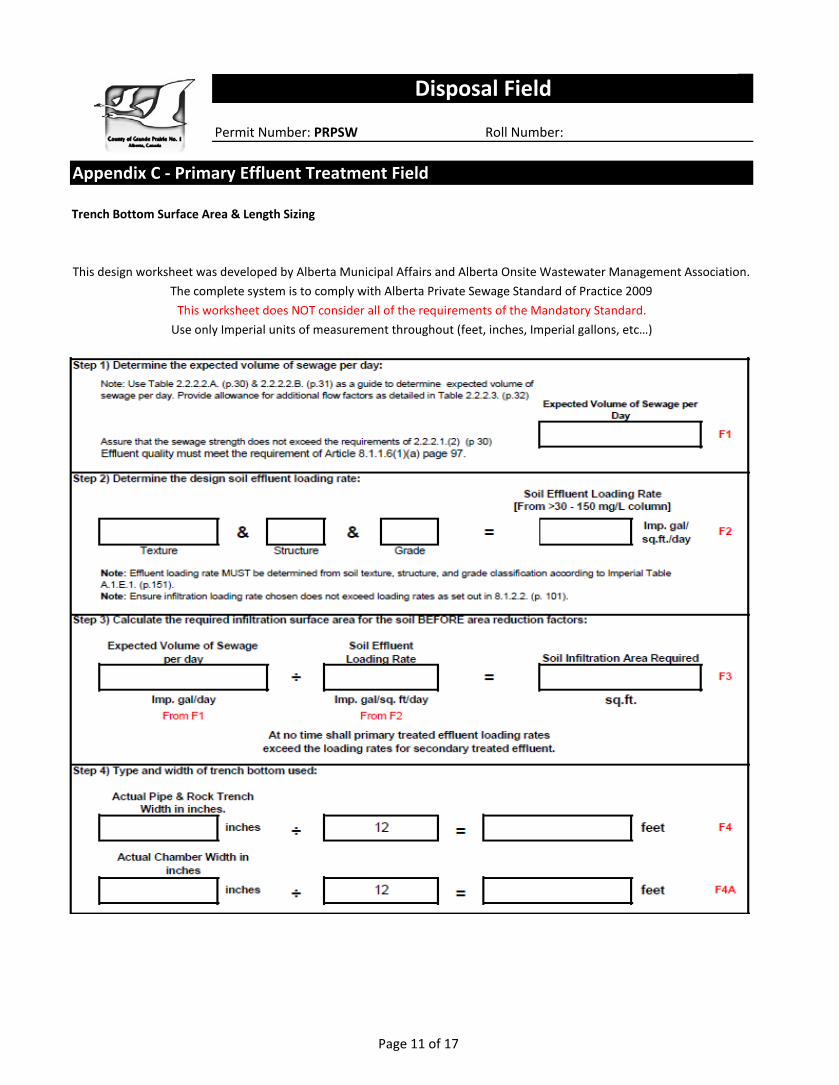
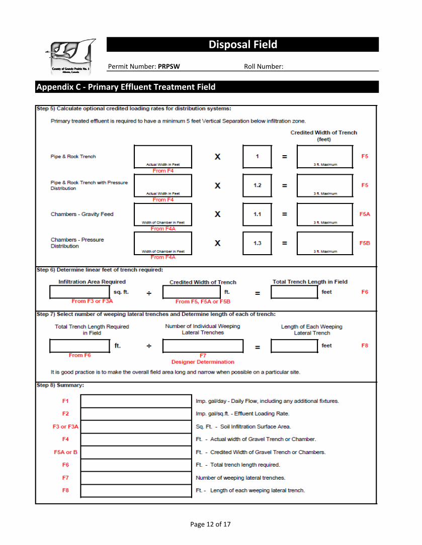
The trench bottom sizing worksheets are completed and attached - Appendix C.
The layout of the laterals have been included with the detailed system schematics and drawings.
The Pressure Distribution, Orifice, Pipe & Pump Sizing worksheets are completed and attached - Ap
The foot long pressure distribution laterals are center fed resulting in (# of) pressure distribution laterals. Each lateral is inch schedule 40 PVC pipe. Each lateral has (# of) 1/8 inch orifices drilled at foot spacing. Orifices will be offset between the two laterals along its length.
The design achieves a minimum of 5 foot pressure head at each orifice, resulting in a design flow of Imp. Gal/Minute from each 1/8 inch orifice.
There are (# of) orifices throughout the effluent pressure distribution system resulting in a total flow of Imp. Gal/minute. An additional 3.2 Imp. Gal/minute is added for the 1/4 inch drain back orifice drilled at the lowest elevation of the effluent piping in the dose tank to achieve drain back of the laterals and supply piping.
The location of the disposal field and the layout of laterals are shown on the Site Evaluation Diagram, Appendix A
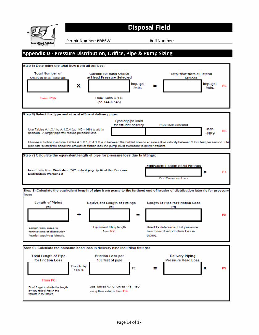
Total flow required for the effluent pressure distribution system is Imp. Gal./minute.
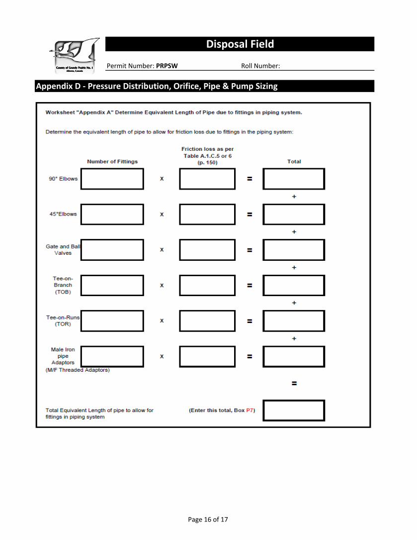
The total length of supply piping from the pump to the start of the pressure distribution laterals is feet. The supply piping is 2 inch Schedule 40 PVC pipe. The allowance for equivalent length of pipe due to fittings is feet of pipe. The equivalent length of pipe is feet. This is detailed in Appendix D.
The friction loss through the feet of piping and filter at the flow of Imp. Gal/min is feet of head pressure.
Page 6 of 17
•
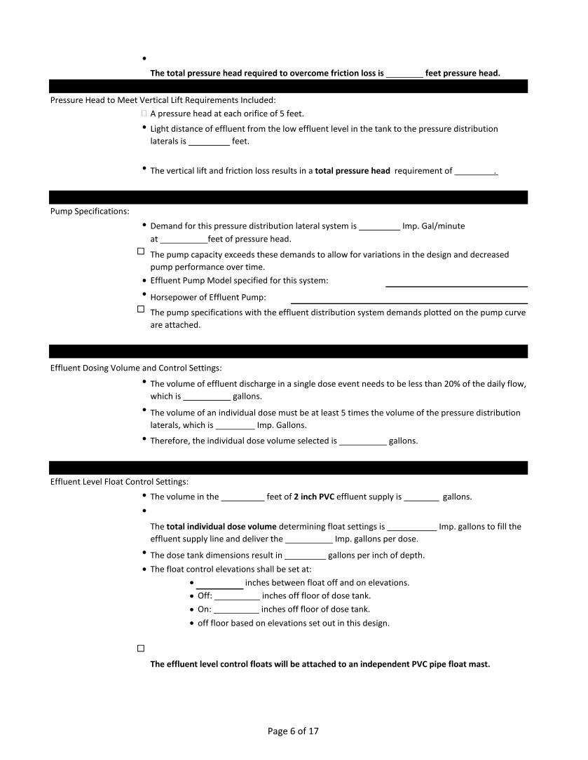
Pressure Head to Meet Vertical Lift Requirements Included:�•
•
Pump Specifications:•
at feet of pressure head.
• Effluent Pump Model specified for this system:• Horsepower of Effluent Pump:
Effluent Dosing Volume and Control Settings:•
•
• Therefore, the individual dose volume selected is gallons.
Effluent Level Float Control Settings:• The volume in the feet of 2 inch PVC effluent supply is gallons.•
• The dose tank dimensions result in gallons per inch of depth.• The float control elevations shall be set at:
• inches between float off and on elevations.• Off: inches off floor of dose tank.• On: inches off floor of dose tank.•
The vertical lift and friction loss results in a total pressure head requirement of .
Demand for this pressure distribution lateral system is Imp. Gal/minute
The pump capacity exceeds these demands to allow for variations in the design and decreased pump performance over time.
The pump specifications with the effluent distribution system demands plotted on the pump curve are attached.
The volume of effluent discharge in a single dose event needs to be less than 20% of the daily flow, which is gallons.
The volume of an individual dose must be at least 5 times the volume of the pressure distribution laterals, which is Imp. Gallons.
The total pressure head required to overcome friction loss is feet pressure head.
A pressure head at each orifice of 5 feet.
Light distance of effluent from the low effluent level in the tank to the pressure distribution laterals is feet.
The total individual dose volume determining float settings is Imp. gallons to fill the effluent supply line and deliver the Imp. gallons per dose.
off floor based on elevations set out in this design.
The effluent level control floats will be attached to an independent PVC pipe float mast.
Page 7 of 17
Operation Monitoring:
Effluent Quality Sampling: Effluent samples can be taken from the effluent dose tank if required.
Initial Operational Setup Parameters:The following activities need to be conducted to commission the system:
Clean the septic tank and effluent chamber of any construction debris.
Operation and Maintenance Manual:
Signature and Closing by the Designer/Installer:
Signature of Designer/Installer:
Flush effluent distribution laterals.
Conduct a squirt test to assess the residual head pressure required by the design is achieved and that the volume from each orifice is within allowed tolerances.
Confirm the correct float levels and ensure this delivers the dose volume required by this design.
The Owner's Manual detailing the design, operation, and maintenance of the installed system will be provided to the owner in accordance with Article 2.1.2.8. of the Standard of Practice.
This design has been developed by . This design meets the requirements of the Alberta Private Sewage System Standard of Practice 2009 unless specifically noted otherwise and in such case special approval is to be obtained prior to proceeding with installation of this design.
The following components are included in the system design and detailed drawings showing locations have been attached:
Monitoring Ports - provided at both ends of the laterals to enable inspection of the effluent ponding depth that may result.
Pressure Distribution Lateral Clean Outs - provided at the end of each pressure distribution lateral with access to grade through an access box suitable for its purpose and anticipated traffic.
Page 8 of 17
Permit Number: PRPSW Roll Number:
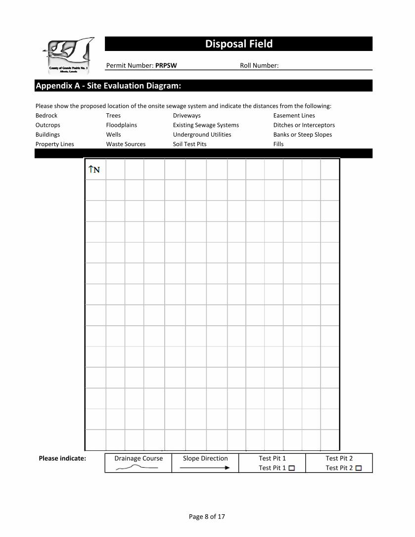
Appendix A - Site Evaluation Diagram:
Please show the proposed location of the onsite sewage system and indicate the distances from the following:Bedrock Trees Driveways Easement LinesOutcrops Floodplains Existing Sewage Systems Ditches or InterceptorsBuildings Wells Underground Utilities Banks or Steep SlopesProperty Lines Waste Sources Soil Test Pits Fills
Please indicate:
Disposal Field
Drainage Course Slope Direction Test Pit 1 Test Pit 2Test Pit 1 Test Pit 2
Page 9 of 17
Permit Number: PRPSW Roll Number:
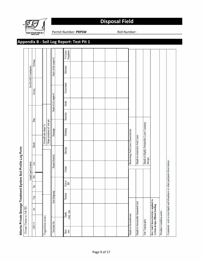
Appendix B - Soil Log Report: Test Pit 1
Disposal Field
Page 10 of 17
Permit Number: PRPSW Roll Number:
Disposal Field
Appendix B - Soil Log Report: Test Pit 2
Page 11 of 17
Permit Number: PRPSW Roll Number:
Trench Bottom Surface Area & Length Sizing
Disposal Field
Appendix C - Primary Effluent Treatment Field
This design worksheet was developed by Alberta Municipal Affairs and Alberta Onsite Wastewater Management Association.The complete system is to comply with Alberta Private Sewage Standard of Practice 2009
This worksheet does NOT consider all of the requirements of the Mandatory Standard.Use only Imperial units of measurement throughout (feet, inches, Imperial gallons, etc…)
Page 12 of 17
Permit Number: PRPSW Roll Number:
Disposal Field
Appendix C - Primary Effluent Treatment Field
Page 13 of 17
Permit Number: PRPSW Roll Number:
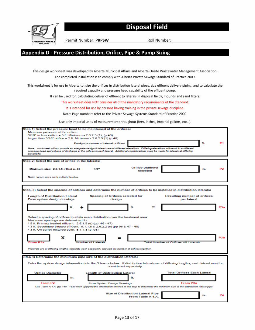
It is intended for use by persons having training in the private sewage discipline.
Note: Page numbers refer to the Private Sewage Systems Standard of Practice 2009.
Use only Imperial units of measurement throughout (feet, inches, Imperial gallons, etc…).
Appendix D - Pressure Distribution, Orifice, Pipe & Pump Sizing
This design worksheet was developed by Alberta Municipal Affairs and Alberta Onsite Wastewater Management Association.
The completed installation is to comply with Alberta Private Sewage Standard of Practice 2009.
This worksheet is for use in Alberta to: size the orifices in distribution lateral pipes, size effluent delivery piping, and to calculate the required capacity and pressure head capability of the effluent pump.
It can be used for: calculating deliver of effluent to laterals in disposal fields, mounds and sand filters.
This worksheet does NOT consider all of the mandatory requirements of the Standard.
Disposal Field
Page 14 of 17
Permit Number: PRPSW Roll Number:
Disposal Field
Appendix D - Pressure Distribution, Orifice, Pipe & Pump Sizing

Page 15 of 17
Permit Number: PRPSW Roll Number:
Appendix D - Pressure Distribution, Orifice, Pipe & Pump Sizing
Disposal Field
Page 16 of 17
Permit Number: PRPSW Roll Number:
Disposal Field
Appendix D - Pressure Distribution, Orifice, Pipe & Pump Sizing


![Tender Document June 9 for the Disposal of LPG Items · PDF filefor the Disposal of LPG Items June 9th ... through your email ids provided. 3. ... [Part – 2 ] : Sales Tax Details](https://img.pdfslide.us/doc/110x75/5a7bf3c67f8b9a72118c5469/tender-document-june-9-for-the-disposal-of-lpg-items-the-disposal-of-lpg-items-june.jpg)