Embed Size (px)
Citation preview
8/16/2019 Dispensig c 740 nordson
http://slidepdf.com/reader/full/dispensig-c-740-nordson 1/240
Century Series
C-740/C-741
Dispensing System
Installation, Operations, andMaintenance Manual
P/N 7209675, Revision A

8/16/2019 Dispensig c 740 nordson
http://slidepdf.com/reader/full/dispensig-c-740-nordson 2/240
8/16/2019 Dispensig c 740 nordson
http://slidepdf.com/reader/full/dispensig-c-740-nordson 3/240
Text P/N 7209676 (Revision A) ©2006
NOTICE
This is an Asymtek publication which is protected by copyright. Original copyright date 2006. No partof this document may be photocopied, reproduced, or translated to another language without theprior written consent of Asymtek. The information contained in this publication is subject to changewithout notice.
Manuals on the Internet
For the convenience of Asymtek customers and field service representatives, copies of Asymtek manualscan be downloaded from:
http://www.asymtek.com/support/manuals.htm
Contact Us
Asymtek welcomes requests for information, comments, and inquiries about its products. Please contactus using the information below:
Headquarters 2762 Loker Avenue WestCarlsbad, CA 92010-6603USA
Tol l Free: 1-800-ASYMTEK (1-800-279-6835)
Tel: +1-760-431-1919
Fax: +1-760-431-2678
E-mail: [email protected]
Website: www.asymtek.com
Technical Support
USA: 1-800-ASYMTEK (1-800-279-6835)
Other regions: www.asymtek.com/support.htm
Trademarks
Asymtek®, Century
®, and Easy Coat
® are registered trademarks of Asymtek.
Microsoft®, Windows
®, and Windows XP
® are registered trademarks of Microsoft Corporation.
Pentium® is a registered trademark of Intel Corporation.Delrin
®, Kalrez
®, Teflon
®, and Viton
® are registered trademarks of E.I. DuPont de Nemours & Co.
8/16/2019 Dispensig c 740 nordson
http://slidepdf.com/reader/full/dispensig-c-740-nordson 4/240
iv
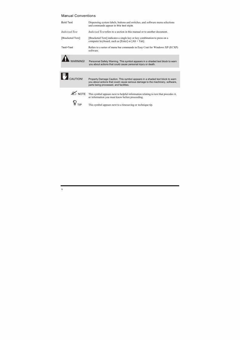
Manual Conventions
Bold Text Dispensing system labels, buttons and switches, and software menu selections
and commands appear in this text style.
Italicized Text Italicized Text refers to a section in this manual or to another document.
[Bracketed Text] [Bracketed Text] indicates a single key or key combination to press on acomputer keyboard, such as [Enter] or [Alt + Tab].
Text>Text Refers to a series of menu bar commands in Easy Coat for Windows XP (ECXP)
software.
WARNING!
Personnel Safety Warning. This symbol appears in a shaded text block to warnyou about actions that could cause personal injury or death.
CAUTION! Property Damage Caution. This symbol appears in a shaded text block to warnyou about actions that could cause serious damage to the machinery, software,parts being processed, and facilities.
NOTE This symbol appears next to helpful information relating to text that precedes it,or information you must know before proceeding.
TIP
This symbol appears next to a timesaving or technique tip.
8/16/2019 Dispensig c 740 nordson
http://slidepdf.com/reader/full/dispensig-c-740-nordson 5/240
Table of Contents v
TABLE OF CONTENTS
1
Introduction.......................................................................................................... 1-1
1.1 Overview..................................................................................................................................1-1
1.2 Safety First ............................................................................................................................... 1-1
1.3
Getting Started.........................................................................................................................1-2
1.3.1
System Status.............................................................................................................. 1-2 1.3.2
Training........................................................................................................................1-2
1.3.3 Manuals Supplied ........................................................................................................1-2
1.4 Basic System Description........................................................................................................1-3
1.4.1
Standard Equipment....................................................................................................1-3
1.4.2
Optional Equipment .....................................................................................................1-3
1.4.3 Fluid Delivery System..................................................................................................1-3
1.5 System Features......................................................................................................................1-4
1.5.1 Front View Features ....................................................................................................1-4
1.5.2
Rear View Features...................................................................................................1-14
2
Safety .................................................................................................................... 2-1
2.1
Overview..................................................................................................................................2-1
2.2
Facility Requirements ..............................................................................................................2-1
2.3 Intended Use............................................................................................................................2-1
2.4
Basic Safety Precautions and Practices..................................................................................2-2
2.4.1 Safety of Personnel ..................................................................................................... 2-2
2.4.2 Material Safety.............................................................................................................2-3
2.4.3
Preventing Dispensing System and Workpiece Damage............................................2-3
2.4.4
High-Pressure Fluids ...................................................................................................2-4
2.5
Laser Radiation........................................................................................................................2-5
2.6 Earthquake Precautions ..........................................................................................................2-6
2.6.1
Personnel.....................................................................................................................2-6 2.6.2 System Safe Mode ......................................................................................................2-6
2.6.3
Movement ....................................................................................................................2-6
2.7
Safety Warning Labels.............................................................................................................2-7
2.8 Emergency Shutdown............................................................................................................2-10
2.8.1 Emergency Shutdown Situations...............................................................................2-11
2.8.2 Emergency Shutdown Recovery ...............................................................................2-11
2.9 Lockout of Electrical and Pneumatic Energy .........................................................................2-12
2.10 Integrated Safety Systems.....................................................................................................2-14
2.10.1 Safety Interlock System.............................................................................................2-14
2.10.2 Light Beacon..............................................................................................................2-17
2.10.3
Electrical Fuses .........................................................................................................2-19
3
Component Description ...................................................................................... 3-1
3.1
Overview..................................................................................................................................3-1
3.2 Safety First ............................................................................................................................... 3-1
3.3 Troubleshooting.......................................................................................................................3-1
3.4 Maintenance ............................................................................................................................3-1
8/16/2019 Dispensig c 740 nordson
http://slidepdf.com/reader/full/dispensig-c-740-nordson 6/240
vi Table of Contents
3.5 Specifications...........................................................................................................................3-2
3.6 Testing .....................................................................................................................................3-2
3.7 Standard Components.............................................................................................................3-3
3.7.1 Computer System........................................................................................................3-3
3.7.2 Easy Coat for Windows XP Software ..........................................................................3-3
3.7.3 Chain Conveyor (C-740)..............................................................................................3-3
3.7.4 Board Pinning Assembly (C-740) ................................................................................3-3
3.7.5
Tooling Plate or Adjustable Tooling Rails (C-741) ......................................................3-3 3.7.6 Integrated Safety Systems ..........................................................................................3-3
3.7.7 Light Beacon................................................................................................................3-4
3.7.8
Low Air Pressure Sensor.............................................................................................3-4
3.7.9
Exhaust Vent Duct .......................................................................................................3-4
3.8 Optional Equipment .................................................................................................................3-5
3.8.1 Bar Code Recognition System ....................................................................................3-5
3.8.2 Board Present Sensor .................................................................................................3-5
3.8.3
Brush Box ....................................................................................................................3-5
3.8.4 Dual Simultaneous Mounting Bracket .........................................................................3-6
3.8.5 Dual Toggle Mounting Bracket ....................................................................................3-6
3.8.6
Laser Fan Width Control System.................................................................................3-7
3.8.7
Flow Monitoring System ..............................................................................................3-8
3.8.8
Hour Meter...................................................................................................................3-8
3.8.9 Laser Pointer Programming Tool.................................................................................3-8
3.8.10 Inline Inverter Module ..................................................................................................3-9
3.8.11 Light Curtain ..............................................................................................................3-10
3.8.12 Low Fluid Sensor (for external reservoir) ..................................................................3-12
3.8.13 Low Solvent Cup Sensor ...........................................................................................3-12
3.8.14 Material Change Over................................................................................................3-12
3.8.15
Upstream and Downstream SMEMA Sensors ..........................................................3-13
3.9
Fluid Delivery Systems ..........................................................................................................3-14
3.9.1
Micro-Adjustment.......................................................................................................3-14
3.9.2 SC-104HS/SC-105HS High Speed Circulating Film Coater......................................3-15
3.9.3 SC-10XVCS Viscosity Control System......................................................................3-16
3.9.4 SC-200 Slim Swirl Applicator.....................................................................................3-17
3.9.5
SC-204HS/SC-205HS High Speed Non-Circulating Film Coater..............................3-19
3.9.6 SC-300 Swirl Coat Applicator ....................................................................................3-20
4
Installation............................................................................................................ 4-1
4.1 Overview..................................................................................................................................4-1
4.2 Safety First ............................................................................................................................... 4-1
4.3 Facility Requirements ..............................................................................................................4-1
4.4
Uncrating and Placing the Dispensing System........................................................................4-2
4.5 Unpacking the Dispensing Area ..............................................................................................4-4
4.6
Unpacking the Accessories Crate............................................................................................4-4
4.7
Leveling the Dispensing System..............................................................................................4-5
4.8
Component Installation............................................................................................................4-6
4.8.1
Installing the Fluid Dispensing Applicator....................................................................4-6
4.8.2 Installing the Monitor.................................................................................................... 4-6
4.8.3 Installing the Keyboard and Mouse .............................................................................4-8
4.8.4 Installing the Light Beacon ........................................................................................4-10
4.9
Pneumatic Connections.........................................................................................................4-12
8/16/2019 Dispensig c 740 nordson
http://slidepdf.com/reader/full/dispensig-c-740-nordson 7/240
Table of Contents vii
4.10 Electrical Connections ...........................................................................................................4-12
4.11 Exhaust Connection...............................................................................................................4-12
4.12 Connecting Power and Air Supply.........................................................................................4-13
4.13 Earthquake Precautions ........................................................................................................4-15
4.14
ECXP Configuration...............................................................................................................4-15
4.14.1
ECW.INI File ..............................................................................................................4-15
4.15
System Configuration.............................................................................................................4-16
4.16 Beacon Configuration ............................................................................................................4-19
5
Power-up and Testing ......................................................................................... 5-1
5.1
Overview..................................................................................................................................5-1
5.2 Safety First ............................................................................................................................... 5-1
5.3 Powering Up the System .........................................................................................................5-1
5.4
Starting Easy Coat for Windows (ECXP).................................................................................5-4
5.5 Testing the System..................................................................................................................5-5
5.6
Robot/Conveyor I/O .................................................................................................................5-5
5.7 Pneumatics ..............................................................................................................................5-8
5.8 Robot (Dispensing Head) Function........................................................................................5-11
5.8.1 ECXP Robot Utilities..................................................................................................5-12
5.9 Conveyor Panel/Mechanics (C-740)......................................................................................5-14
5.9.1
ECXP Conveyor Utilities............................................................................................5-15
5.9.2 Inverter.......................................................................................................................5-15
5.10
Dispensing System Options...................................................................................................5-16
5.10.1 Laser Fan Width Control............................................................................................5-16
5.10.2 Flow Meter .................................................................................................................5-17
5.10.3
Bar Code Scanner .....................................................................................................5-17
6
Operation.............................................................................................................. 6-1
6.1
Overview..................................................................................................................................6-1
6.2
Basic System Operation ..........................................................................................................6-1
6.3
Conformal Coating...................................................................................................................6-1
6.4 Detailed Operation (C-740)......................................................................................................6-2
6.4.1 Dispensing Process.....................................................................................................6-2
6.5 Computer System....................................................................................................................6-4
6.5.1 ECXP Software............................................................................................................6-4
6.6 Dispensing Operations.............................................................................................................6-6
6.6.1
Robot Concepts...........................................................................................................6-6 6.6.2 Coordinate Systems ....................................................................................................6-7
6.7
Conveyor Operations...............................................................................................................6-8
6.7.1 Chain Conveyor (C-740)..............................................................................................6-8
6.8 Dispensing System Controls..................................................................................................6-10
6.8.1 Power Buttons and Switches.....................................................................................6-10
6.8.2 Control Panel .............................................................................................................6-12
6.8.3 Pneumatic Regulators and Gauges...........................................................................6-18
6.8.4 Air Assist Regulator and Gauge ................................................................................6-22
8/16/2019 Dispensig c 740 nordson
http://slidepdf.com/reader/full/dispensig-c-740-nordson 8/240
viii Table of Contents
6.9 System Startup/Shutdown.....................................................................................................6-23
6.9.1
Startup .......................................................................................................................6-23
6.9.2
Shutdown...................................................................................................................6-24
6.9.3 Daily Routine Procedures..........................................................................................6-26
6.10 Conformal Coating Setup Procedures...................................................................................6-27
6.10.1 Performing a Characterization...................................................................................6-27
6.10.2 Developing a Coating Program .................................................................................6-27
6.10.3 Performing a System Test .........................................................................................6-28
6.11 Loading a Program ................................................................................................................6-29
6.12 Running a Program................................................................................................................6-31
6.12.1 Operator Screen ........................................................................................................6-31
6.12.2 Edit Screen ................................................................................................................6-33
6.13
Production Statistics ..............................................................................................................6-34
6.13.1 Database Utility..........................................................................................................6-34
7
Configuration and Characterization ...................................................................7-1
7.1
Overview..................................................................................................................................7-1
7.2 Safety First ............................................................................................................................... 7-1
7.3
Record Keeping .......................................................................................................................7-1
7.4
Tool Configuration....................................................................................................................7-2
7.4.1 Tool Offset ...................................................................................................................7-2
7.5 Characterization.......................................................................................................................7-4
7.6 Fan Width Configuration..........................................................................................................7-7
7.6.1
Fan Width Setup..........................................................................................................7-7
7.7
Fixture Configuration................................................................................................................7-8
7.7.1
Fixture Constraint Location..........................................................................................7-8
7.8 Conveyor Configuration.........................................................................................................7-11
7.9
Inverter Configuration ............................................................................................................7-13
7.10
Robot Configuration...............................................................................................................7-14
7.11 Bar Code Scanner Configuration...........................................................................................7-15
7.11.1 PSC5312 (Hand-Held) Scanner Configuration..........................................................7-15
7.11.2
MS810 (Fixed Mount) Scanner Configuration ...........................................................7-15
7.12
Reconfigure............................................................................................................................7-17
8
Troubleshooting ..................................................................................................8-1
8.1 Overview..................................................................................................................................8-1
8.2
Basic System Troubleshooting ................................................................................................8-1
9
Maintenance .........................................................................................................9-1
9.1 Overview..................................................................................................................................9-1
9.2 Safety First ............................................................................................................................... 9-1
9.3
Hazardous Materials................................................................................................................9-1
9.4
Record Keeping .......................................................................................................................9-1
8/16/2019 Dispensig c 740 nordson
http://slidepdf.com/reader/full/dispensig-c-740-nordson 9/240
Table of Contents ix
9.5 Routine Maintenance Procedures ...........................................................................................9-2
9.5.1
Filling the Fluid Reservoir ............................................................................................9-4
9.5.2
Changing Material/Flushing Fluid System...................................................................9-5
9.5.3 Emptying the Water Trap.............................................................................................9-6
9.5.4 Cleaning the Fluid Filter...............................................................................................9-7
9.5.5
Lubricating the Mechanical Drive Cables ....................................................................9-8
9.5.6
X-Axis Lubrication........................................................................................................9-9
9.5.7 Tensioning the Cables...............................................................................................9-11
10
Parts Replacement.............................................................................................10-1
10.1 Overview................................................................................................................................10-1
10.2 Safety First.............................................................................................................................10-1
10.2.1 Hazardous Materials..................................................................................................10-1
10.3 Parts Ordering Information ....................................................................................................10-2
10.3.1 Placing Your Order ....................................................................................................10-2
10.3.2 Shipping Instructions .................................................................................................10-2
10.3.3 Warranty ....................................................................................................................10-2
10.3.4
Credit and Exchanges ...............................................................................................10-2
10.3.5
Return Material Authorization....................................................................................10-2
10.4
Cleaning and Inspection ........................................................................................................10-3
10.5 Unpacking and Inspecting Replacement Parts......................................................................10-3
10.6
Record Keeping .....................................................................................................................10-3
10.7
Gaining Access to Dispensing System Components ............................................................10-4
10.8 Replacing Conveyor Chains (C-740).....................................................................................10-5
10.9 Replacing Fuses ....................................................................................................................10-8
10.9.1 Replacement Fuses...................................................................................................10-8
10.9.2
Replacing Main Line Fuses .....................................................................................10-10
10.9.3
Replacing Panel-Mounted Fuses ............................................................................10-12
10.10
Replacing Control Modules..................................................................................................10-14
11
Specifications ....................................................................................................11-1
11.1
Overview................................................................................................................................11-1
11.2
Safety First.............................................................................................................................11-1
11.3 Facility Requirements ............................................................................................................11-2
11.4 Drive System..........................................................................................................................11-2
11.5
Conveyor................................................................................................................................11-2
11.6 Dispensing Area.....................................................................................................................11-3
11.7 Software.................................................................................................................................11-3
Appendix A - Pneumatic Diagrams.......................................................................... A-1
A.1
Overview ..................................................................................................................................A-1
A.2 Safety First...............................................................................................................................A-1
A.3 List of Pneumatic Diagrams.....................................................................................................A-1
8/16/2019 Dispensig c 740 nordson
http://slidepdf.com/reader/full/dispensig-c-740-nordson 10/240
x Table of Contents
Appendix B - Electrical Diagrams............................................................................ B-1
B.1 Overview ..................................................................................................................................B-1
B.2
Safety First...............................................................................................................................B-1
B.3 List of Electrical Diagrams .......................................................................................................B-1
Appendix C - Illustrated Parts Lists......................................................................... C-1
C.1
Overview................................................................................................................................. C-1
C.2
Safety First.............................................................................................................................. C-1
Appendix D - Dispensing System Electronics........................................................ D-1
D.1 I/O Communications ............................................................................................................... D-1
D.2
Dispenser Electronics............................................................................................................. D-2
D.3
CC-201-W Conveyor Electronics (C-740 only)....................................................................... D-3
D.4 Auxiliary I/O Connector Pinouts.............................................................................................. D-4
D.5
Conveyor Controller Rear Connections (C-740 only) ............................................................. D-6
D.6
Robot ...................................................................................................................................... D-7
D.7
Robot Main Board................................................................................................................... D-7
D.8 Rear Connections ................................................................................................................... D-8
Glossary..................................................................................................................... G-1
Index............................................................................................................................. I-1
8/16/2019 Dispensig c 740 nordson
http://slidepdf.com/reader/full/dispensig-c-740-nordson 11/240
Table of Contents xi
Table of Figures
Figure 1-1 C-740/C-741 Front View.....................................................................................................1-5
Figure 1-2 C-740/C-741 Control Panel ................................................................................................1-7
Figure 1-3 C-740 Dispensing Area ...................................................................................................... 1-9
Figure 1-4 C-740/C-741 Dispensing Area Close-up..........................................................................1-11
Figure 1-5 C-740 Lower Front Cabinet ..............................................................................................1-13
Figure 1-6 Rear View (with Material Changeover Option) .................................................................1-15 Figure 1-7 Right Rear Close-up.........................................................................................................1-17
Figure 1-8 Lower Rear View .............................................................................................................. 1-19
Figure 2-1 Earthquake Precautions .....................................................................................................2-6
Figure 2-2 Safety Warning Labels, Front View ....................................................................................2-8
Figure 2-3 Safety Warning Labels, Rear View.....................................................................................2-9
Figure 2-4 EMO/Main Circuit Breaker Locations ...............................................................................2-10
Figure 2-5 Lockout of Electrical Power ..............................................................................................2-12
Figure 2-6 Lockout of Pneumatic Pressure........................................................................................2-13
Figure 2-7 Safety Interlock Keyswitch................................................................................................2-14
Figure 2-8 Optional Interlock Warning Tag........................................................................................2-15
Figure 2-9 Interlock Shutdown Recovery...........................................................................................2-16
Figure 2-10 Light Beacon/System Status LED’s..................................................................................2-17
Figure 3-1 Brush Box ...........................................................................................................................3-5
Figure 3-2 Dual Simultaneous Mounting Bracket ................................................................................3-6
Figure 3-3 Laser Fan Width Control System........................................................................................3-7
Figure 3-4 Flow Meter ..........................................................................................................................3-8
Figure 3-5 Hour Meter ..........................................................................................................................3-8
Figure 3-6 Inline Inverter Module .........................................................................................................3-9
Figure 3-7 Light Curtain (option) ........................................................................................................3-10
Figure 3-8 Material Change Over Option...........................................................................................3-12
Figure 3-9 Upstream and Downstream SMEMA Sensors .................................................................3-13
Figure 3-10 SC-104HS High Speed Circulating Film Coater...............................................................3-15
Figure 3-11 SC-105HS High Speed Circulating Film Coater...............................................................3-15
Figure 3-12 Century Series C-740 with Viscosity Control System.......................................................3-16
Figure 3-13 SC-200 Slim Swirl Applicator............................................................................................3-17
Figure 3-14 Tri-Mode Swirl Box ........................................................................................................... 3-18
Figure 3-15 SC-204HS Non-Circulating Film Coater...........................................................................3-19
Figure 3-16 SC-205 Non-Circulating Film Coater................................................................................3-19
Figure 3-17 SC-300 Swirl Coat Applicator...........................................................................................3-20
Figure 4-1 Leveling the Dispensing System ........................................................................................4-5
Figure 4-2 Installing the Monitor...........................................................................................................4-7
Figure 4-3 Installing the Keyboard and Mouse ....................................................................................4-9
Figure 4-4 Installing the Light Beacon ...............................................................................................4-11
Figure 4-5 Connecting the Facilities Power and Air Supply...............................................................4-14
Figure 4-6 ECXP Operator Screen ....................................................................................................4-16
Figure 4-7 ECXP Edit Screen ............................................................................................................ 4-17
Figure 4-8 ECXP Configure Dialog Box.............................................................................................4-17
Figure 4-9 Log Trigger Faults Dialog Box ..........................................................................................4-19
Figure 4-10 Subsystem Dialog Box .....................................................................................................4-20
Figure 5-1 Power, Air, and Exhaust Connections................................................................................5-2
Figure 5-2 Control Panel Buttons.........................................................................................................5-3
Figure 5-3 Starting ECXP.....................................................................................................................5-4
Figure 5-4 ECXP Edit Screen - Utilities Menu .....................................................................................5-5
Figure 5-5 Robot IO Tool ..................................................................................................................... 5-6
Figure 5-6 Conveyor IO Tool................................................................................................................5-7
8/16/2019 Dispensig c 740 nordson
http://slidepdf.com/reader/full/dispensig-c-740-nordson 12/240
xii Table of Contents
Figure 5-7 Main Air Regulator and Gauge...........................................................................................5-8
Figure 5-8 Stop/Clamp Air Regulator and Gauge................................................................................5-9
Figure 5-9 Fluid Pressure Pneumatic Controls..................................................................................5-10
Figure 5-10 Robot/Conveyor Position Controls ...................................................................................5-11
Figure 5-11 ECXP Edit Screen – Robot Utilities..................................................................................5-12
Figure 5-12 Pendant Dialog Box..........................................................................................................5-13
Figure 5-13 ECXP Edit Screen - Conveyor Utilities Menu...................................................................5-15
Figure 5-14 ECXP Edit Screen - Pressure Adjust Menu .....................................................................5-16
Figure 5-15 Pressure Output Dialog Box.............................................................................................5-17
Figure 6-1 Operational Flow Chart.......................................................................................................6-3
Figure 6-2 Computer Front Panel ........................................................................................................6-5
Figure 6-3 Reference Frames..............................................................................................................6-7
Figure 6-4 Manual Conveyor Width Adjustment ..................................................................................6-9
Figure 6-5 Power Buttons and Switches............................................................................................6-10
Figure 6-6 Control Panel Functional Areas........................................................................................6-12
Figure 6-7 Adjusting Main Air Pressure .............................................................................................6-19
Figure 6-8 Adjusting Conveyor Stop/Clamp Air Pressure..................................................................6-20
Figure 6-9 Adjusting Fluid Pressure...................................................................................................6-21
Figure 6-10 Air Assist Regulator and Gauge .......................................................................................6-22
Figure 6-11 Setup Flow Chart..............................................................................................................6-28
Figure 6-12 Loading a Program - Operator Screen .............................................................................6-29 Figure 6-13 Loading a Program - Edit Screen .....................................................................................6-30
Figure 6-14 Running a Program - Operator Screen (C-740) ...............................................................6-31
Figure 6-15 Running a Program - Operator Screen (C-741) ...............................................................6-32
Figure 6-16 Running a Program - Edit Screen.....................................................................................6-33
Figure 7-1 Tool Offset ..........................................................................................................................7-2
Figure 7-2 Tool Configuration Dialog Box............................................................................................7-3
Figure 7-3 ECXP Characterization Wizard Dialog Box........................................................................7-4
Figure 7-4 Characterization Sheet .......................................................................................................7-5
Figure 7-5 Material Characterization....................................................................................................7-6
Figure 7-6 Fixture Constraint Location.................................................................................................7-8
Figure 7-7 ECXP Fixture Configuration ...............................................................................................7-9
Figure 7-8 Teaching XYZ Coordinates .............................................................................................. 7-10
Figure 7-9 Conveyor Settings Dialog Box..........................................................................................7-11
Figure 7-10 Robot Settings Dialog Box................................................................................................7-14
Figure 9-1 Filling the Fluid Reservoir ...................................................................................................9-4
Figure 9-2 Water Trap..........................................................................................................................9-6
Figure 9-3 Cleaning the Fluid Filter......................................................................................................9-7
Figure 9-4 Mechanical Drive Cable Location.......................................................................................9-8
Figure 9-5 Lubricating the X-Axis Bearings .......................................................................................9-10
Figure 9-6 System Access (Rear View).............................................................................................9-12
Figure 9-7 ECXP Tension Procedure ................................................................................................9-13
Figure 10-1 System Access Locations (Rear View).............................................................................10-4
Figure 10-2 Creating Slack in the Chain ..............................................................................................10-5
Figure 10-3 Removing the Retainer Clip..............................................................................................10-6
Figure 10-4 Removing the Female Link...............................................................................................10-6
Figure 10-5 Removing the Master Link (Male Link) .............................................................................10-6
Figure 10-6 Installing the Chain on the Sprocket Rail..........................................................................10-6
Figure 10-7 Inserting the Master Link (Male Link) ...............................................................................10-7
Figure 10-8 Inserting the Master Link (Female Link) ..........................................................................10-7
Figure 10-9 Installing the Retainer Clip................................................................................................10-7
Figure 10-10 Conveyor Controller Fuse Locations................................................................................10-9
Figure 10-11 Main Line Fuse Replacement.........................................................................................10-11
Figure 10-12 Panel-Mounted Fuse Replacement................................................................................10-13
8/16/2019 Dispensig c 740 nordson
http://slidepdf.com/reader/full/dispensig-c-740-nordson 13/240
Table of Contents xiii
Figure C-1 Parts List – C-740 Front Open View.................................................................................. C-2
Figure C-2 Parts List – C-740 Rear Open View .................................................................................. C-3
Figure C-3 Parts List – C-740 Conveyor Components........................................................................ C-4
Figure C-4 Parts List – C-740 Computer Components ....................................................................... C-5
Figure C-5 Parts List – C-741Front View............................................................................................. C-6
Figure C-6 Parts List – C-741 Rear Open View .................................................................................. C-7
Figure C-7 Parts List – C-741 Dispensing Area Components............................................................. C-8
Figure C-8 Parts List – C-741 Computer Components ....................................................................... C-9
Figure D-1 Conveyor Controller Rear Connections............................................................................. D-6
Figure D-2 C-740 Rear Connections................................................................................................... D-9
8/16/2019 Dispensig c 740 nordson
http://slidepdf.com/reader/full/dispensig-c-740-nordson 14/240
xiv Table of Contents
Table of Tables
Table 2-1 Laser Fan Width Control Specifications .............................................................................2-5
Table 2-2 Safety Warning Symbols ....................................................................................................2-7
Table 2-3 Light Beacon Color Indications.........................................................................................2-18
Table 2-4 Replaceable Fuse Descriptions........................................................................................2-19
Table 3-1 Light Curtain Status Indicators .........................................................................................3-11
Table 3-2 C-740/C-741 Fluid Dispensing Applicators ......................................................................3-14
Table 5-1 ECXP Robot Utilities Commands .....................................................................................5-13
Table 5-2 ECXP Utilities Commands (Robot)...................................................................................5-13
Table 5-3 ECXP Conveyor Utilities Commands ...............................................................................5-15
Table 6-1 Power Buttons and Switches............................................................................................6-11
Table 6-2 Download Program Controls ............................................................................................ 6-13
Table 6-3 Motion Controls................................................................................................................. 6-14
Table 6-4 System Status Controls....................................................................................................6-16
Table 6-5 Recommended Pressure Settings....................................................................................6-18
Table 6-6 Daily Routine Procedures.................................................................................................6-26
Table 7-1 Conveyor Settings ............................................................................................................ 7-12
Table 7-2 Inverter Configuration.......................................................................................................7-13
Table 8-1 Basic System Troubleshooting...........................................................................................8-1
Table 9-1 Routine Maintenance Procedures ......................................................................................9-2
Table 10-1 Replaceable Fuses...........................................................................................................10-8
Table 11-1 Facility Requirements.......................................................................................................11-2
Table 11-2 Drive System .................................................................................................................... 11-2
Table 11-3 Conveyor Specifications ...................................................................................................11-2
Table 11-4 Dispensing Area Specifications........................................................................................11-3
Table 11-5 Software Specifications ....................................................................................................11-3
Table A-1 Pneumatic Diagram............................................................................................................A-1
Table B-1 Electrical Diagrams.............................................................................................................B-1
Table C-1 Illustrated Parts Lists ......................................................................................................... C-1
Table D-1 Dispenser Electronics........................................................................................................ D-2
Table D-2 Bit Mapping and Functions................................................................................................ D-3
Table D-3 Connector 60-0255-00 PCA Pin Designation.................................................................... D-5
Table D-4 Conveyor Controller Rear Connections............................................................................. D-6
Table D-5 Century Series C-740 Dispensing System Rear Connections .......................................... D-8
8/16/2019 Dispensig c 740 nordson
http://slidepdf.com/reader/full/dispensig-c-740-nordson 15/240
Introduction 1-1
1 Introduction
1.1 Overview
Congratulations on your choice of the Century C-740/C-741 Series Dispensing System! This manual isintended primarily as a reference for production operators, process engineers, and service technicians.
However, others unfamiliar with Asymtek products may also find this manual useful as a generalintroduction to the system.
The Century C-740/C-741 Series Dispensing Systems are designed to meet the diverse needs of the
conformal coating market. The C-740/C-741 systems provide consistent, uniform dispensing of a variety
of conformal coating materials for both conveyorized (C-740) and batch (C-741) coating applications.
Patented dispensing technology replaces traditional dip, brush, handgun, and aerosol spray systems with
field-proven, repeatable delivery of solvent-based and 100-percent solids materials. The system virtually
eliminates the requirement for labor-intensive board masking, providing accurately controlled patterns,
film builds, and production flexibility in an automated process. Film thickness is achieved in a single pass
with little or no masking and with virtually no overspray.
This section covers the following topics:
• Getting Started • Standard
• System Status • Optional Equipment
• Training • Fluid Delivery System
• Manuals Supplied • Front View Features
• Basic System Description • Rear View Features
1.2 Safety First
Operation of your C-740/C-741 Dispensing System involves heat, air pressure, pneumatic devices,
electrical power, mechanical devices, and the use of hazardous materials. Read this manual in its entirety
before attempting any system or component operation. It is essential for all personnel working on or
around the dispensing system to fully understand the hazards, risks, and safety precautions associated
with operating the dispensing system. When properly operated and maintained, the dispensing systemshould be safe and reliable. Refer to Section 2 - Safety for additional information.
WARNING! CAUTION! Consult the Material Safety Data Sheet (MSDS) for all fluids used with thedispensing system. The MSDS provides material usage instructions, disposalinstructions, and safety precautions.
8/16/2019 Dispensig c 740 nordson
http://slidepdf.com/reader/full/dispensig-c-740-nordson 16/240
1-2 Introduction
1.3 Getting Started
1.3.1 System Status
The Century Series Dispensing System is installed and tested on-site by an Asymtek technician. To
ensure that the system is in good working order, only Asymtek-trained technicians should install, move,
or service the system.
1.3.2 Training
In order to optimize the full capabilities and features of your dispensing system, Asymtek recommends
certification for all operators, technicians, and engineers using, programming, and servicing the
dispensing system.
Asymtek offers several levels of training courses to enable customer operators, technicians, and engineers
to become fully certified in dispensing system safety, operation, hardware, software, and fluid
applications. For more information on training courses and certification, contact Asymtek.
1.3.3 Manuals Supplied
Your Century Series Dispensing System arrives with manuals for installation and operation of major
system components and software. For some system components, you may receive Original Equipment
Manufacturer (OEM) manuals. Generally, these OEM manuals are only needed for reference and
advanced troubleshooting. Consult only Asymtek manuals, unless directed to do otherwise by Asymtek
Technical Support or Asymtek documentation. For the convenience of Asymtek customers, manuals may
be downloaded from: http://www.asymtek.com/support/manuals.htm.
Below is a sample list of manuals that may be shipped with a Century Series Dispensing System.
Optional manuals listed may or may not be included, depending on your system’s configuration.
• Century Series C-740/C-741 Installation, Operations, and Maintenance Manual (P/N 194589)
• Century Series C-740/C-741 Quick Operations Manual (P/N 211035)
• Fluid Dispensing System Manual (specific to your application)
- SC-100 Series High Speed Film Coater (P/N 108384)
- SC10XVCS Viscosity Control System (P/N 7204869)
- SC-204HS High Speed Non-Circulating Film Coater (P/N 106966)
- SC-205 Non-Circulating Film Coater (P/N 107101)
- SC-200 Slim Swirl Applicator (P/N 303776)
- SC-300 Swirl Coat Applicator (P/N 7201127)
• Easy Coat for Windows User Guide (P/N 7203045)
Optional:
• Laser Fan Width Control Owner’s Manual (P/N 7201445)
• Flow Monitoring System Installation, Operations, and Maintenance Manual
• Original Equipment Manufacturer Manuals (as applicable)
8/16/2019 Dispensig c 740 nordson
http://slidepdf.com/reader/full/dispensig-c-740-nordson 17/240
Introduction 1-3
1.4 Basic System Description
All Century C-740/C-741 Series Dispensing Systems have a standard platform. Optional components may
be added to suit your particular requirements. Your system was configured for your application at the
Asymtek factory prior to shipping. Standard and optional equipment is listed below. Brief descriptions of
all features are found later in this section.
1.4.1 Standard Equipment
• Computer System • Integrated Safety Systems
• Easy Coat for Windows XP software • Light Beacon
• Chain Conveyor (C-740) • Low Air Pressure Sensor
• Board Pinning Assembly (C-740) • Exhaust Vent Duct
• Tooling Plate/Adjustable Tooling Rails (C-741)
1.4.2 Optional Equipment
• Bar Code Recognition System • Laser Pointer Programming Tool
• Board Present Sensor • Inline Inverter Module
• Brush Box • Light Curtain
• Dual Simultaneous Mounting Bracket • Low Fluid Sensor (for external reservoir)
• Dual Toggle Mounting Bracket • Low Solvent Cup Sensor
• Laser Fan Width Control System • Material Change Over
• Flow Monitoring System • Upstream /Downstream SMEMA Sensors
• Hour Meter
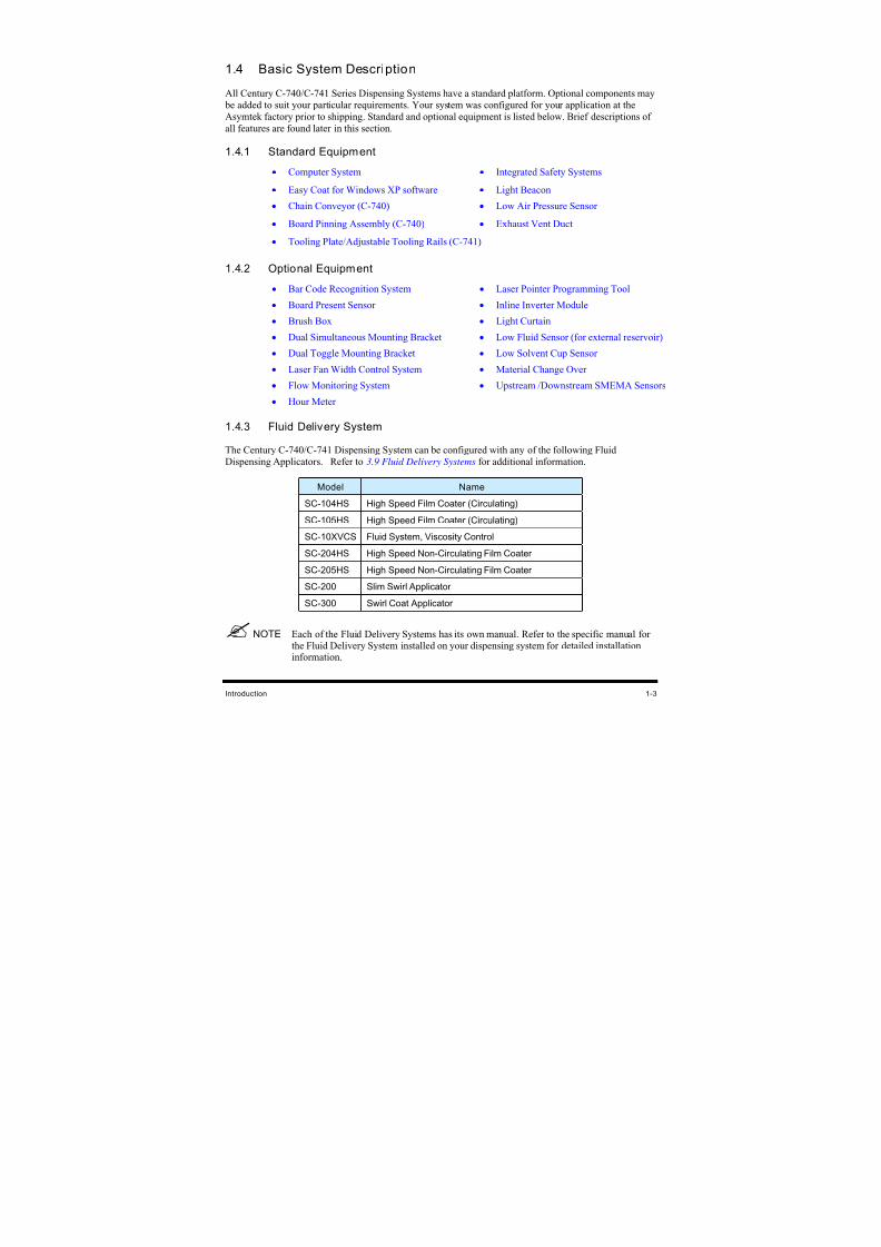
1.4.3 Fluid Delivery System
The Century C-740/C-741 Dispensing System can be configured with any of the following Fluid
Dispensing Applicators. Refer to 3.9 Fluid Delivery Systems for additional information.
Model Name
SC-104HS High Speed Film Coater (Circulating)
SC-105HS High Speed Film Coater (Circulating)
SC-10XVCS Fluid System, Viscosity Control
SC-204HS High Speed Non-Circulating Film Coater
SC-205HS High Speed Non-Circulating Film Coater
SC-200 Slim Swirl Applicator
SC-300 Swirl Coat Applicator
NOTE Each of the Fluid Delivery Systems has its own manual. Refer to the specific manual forthe Fluid Delivery System installed on your dispensing system for detailed installationinformation.
8/16/2019 Dispensig c 740 nordson
http://slidepdf.com/reader/full/dispensig-c-740-nordson 18/240
1-4 Introduction
1.5 System Features
The figures in this section show features of the dispensing system. Callouts locate major components,
options, and switches. The item numbers associated with the descriptions correspond to the callout
numbers in the illustration. Detailed operating instructions for some of these features are treated in other
sections of this manual. Unless otherwise noted, Figures 1-1 to 1-8 apply to both the C-740 and C-741
models.
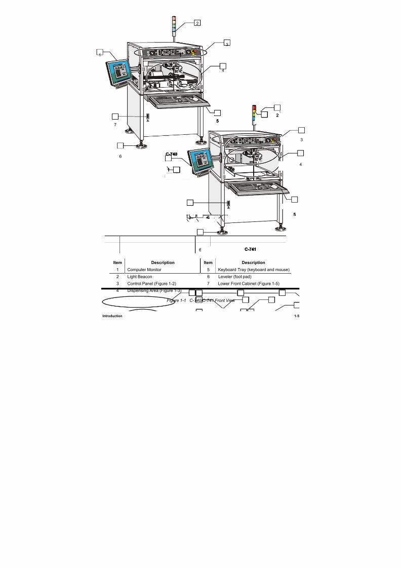
1.5.1 Front View Features
Below are functional descriptions of C-740/C-741 Series Dispensing System components shown in
Figure 1-1.
1. Computer Monitor
The Computer Monitor provides the operator with Easy Coat for Windows XP (ECXP)
software displays.
2. Light Beacon
The Light Beacon is a warning device for the operator. The beacon signals a dispensing status
condition by displaying a colored light and/or issuing an audible tone. Refer to Section 2 - Safety for
additional information.
3. Control Panel
The Control Panel buttons and switches let you control certain programming and run functions. You
can move the Robot (Dispensing Head) and the Conveyor, enable the Safety Interlock, make an
emergency stop, check dispensing status, and adjust valve controls. Refer to Section 6 - Operation
for detailed descriptions of Control Panel functions.
NOTE The terms Robot and Dispensing Head are synonymous and are used interchangeablythroughout this manual.
4. Dispensing Area
The Dispensing Head, Solvent Cups, Conveyor, Stop Pins, and Board Sensors are all located in the
dispensing area. (See Figure 1-3 and Figure 1-4).
5. Keyboard Tray
The Keyboard and Mouse Tray holds and protects the Computer System keyboard and mouse.
6. Levelers (Foot Pads)
The Levelers are the footpads of the dispensing system. The Levelers are adjusted during installationand should not need attention unless the system is moved to a new location. To protect the
dispensing system from moving during an earthquake, the Levelers should be anchored to the floor
with bolt anchors. See 2.6 Earthquake Precautions.
7. Lower Front Cabinet
The Lower Front Cabinet allows access to the system Computer, Conveyor Controller Module, and
the Tri-Mode Swirl Box (for the Swirl Coat Module only). See Figure 1-5.
8/16/2019 Dispensig c 740 nordson
http://slidepdf.com/reader/full/dispensig-c-740-nordson 19/240
Introduction 1-5
Item Description Item Description
1 Computer Monitor 5 Keyboard Tray (keyboard and mouse)
2 Light Beacon 6 Leveler (foot pad)
3 Control Panel (Figure 1-2) 7 Lower Front Cabinet (Figure 1-5)
4 Dispensing Area (Figure 1-3)
Figure 1-1 C-740/C-741 Front View
C-741
C-740
1
1
2
2
3
3
4
5
4
5
7
6
6
7
C-741
C-740
1
2
3
4
5
5
7
6 C-741
C-740
1
2
3
4
5
5
7
6
8/16/2019 Dispensig c 740 nordson
http://slidepdf.com/reader/full/dispensig-c-740-nordson 20/240
8/16/2019 Dispensig c 740 nordson
http://slidepdf.com/reader/full/dispensig-c-740-nordson 21/240
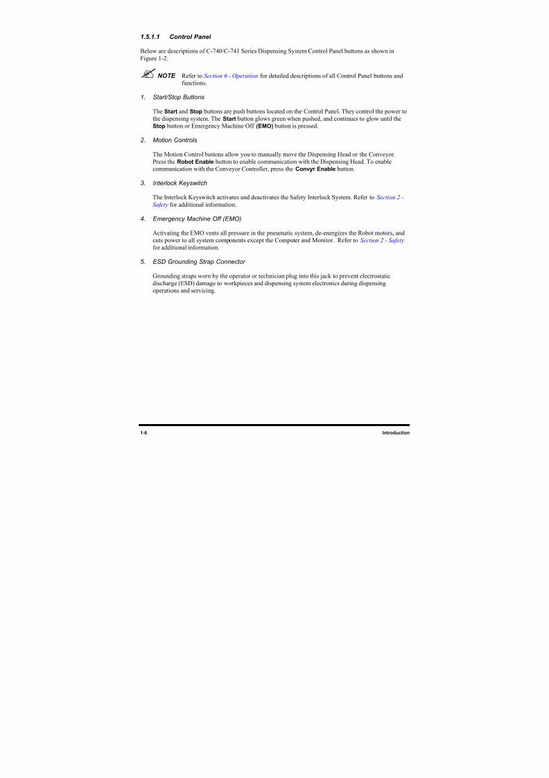
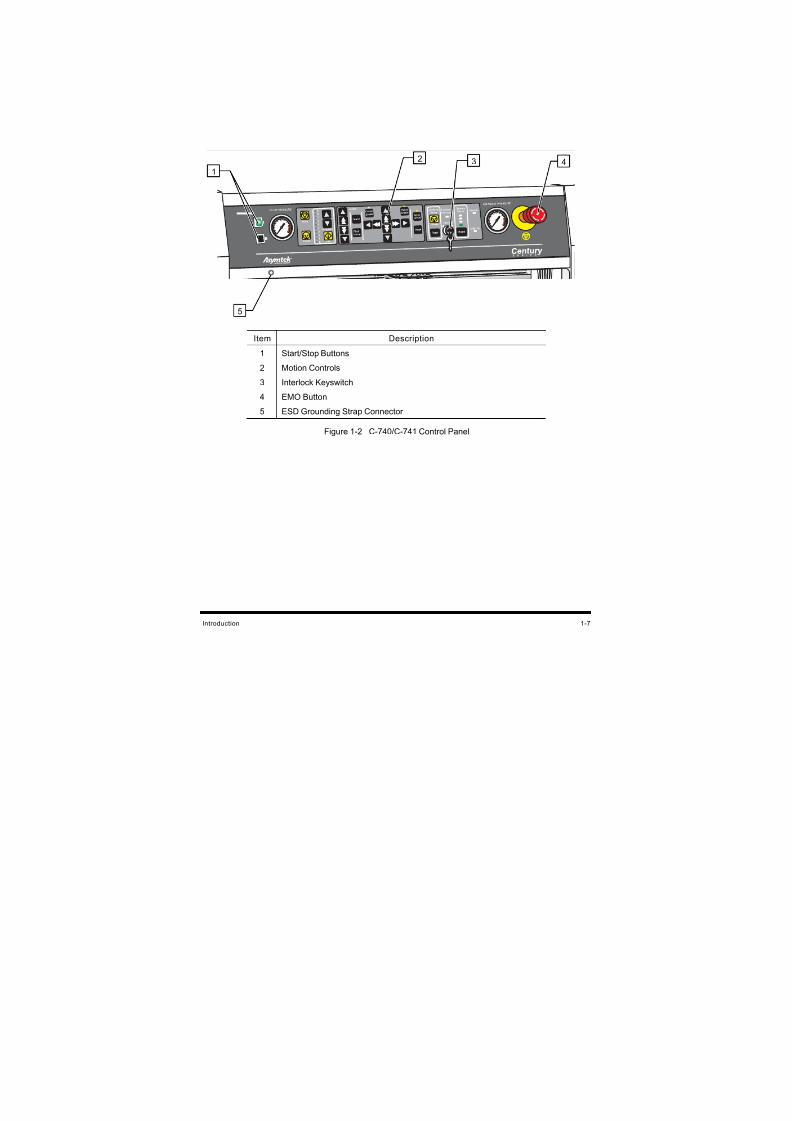
Introduction 1-7
Item Description
1 Start/Stop Buttons
2 Motion Controls
3 Interlock Keyswitch
4 EMO Button
5 ESD Grounding Strap Connector
Figure 1-2 C-740/C-741 Control Panel
43
5
1
2
8/16/2019 Dispensig c 740 nordson
http://slidepdf.com/reader/full/dispensig-c-740-nordson 22/240
1-8 Introduction
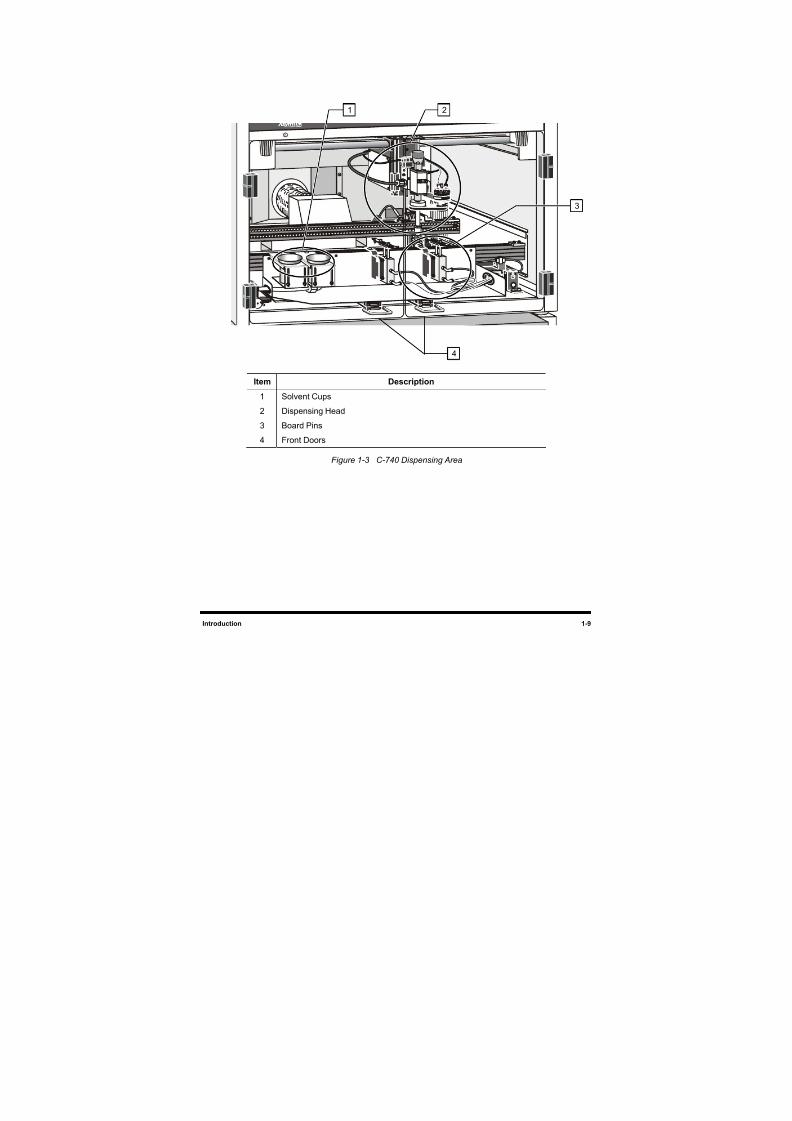
1.5.1.2 Dispensing Area
Below are functional descriptions of C-740/C-741 Series Dispensing System components shown in
Figure 1-3.
1. Solvent Cups
The Century C-740 conveyorized system has two 125 ml stainless steel cups that are installed onseparate brackets mounted to the front Conveyor rail. One cup holds solvent for cleaning the
dispensing needle. A second cup is used for the purging of conformal coating fluid. The solvent cups
can be positioned as desired by the operator on the C-741 batch dispensing system.
2. Dispensing Head (Robot)
The Dispensing Head moves in the XYZ planes. It is controlled through the ECXP software and the
Control Panel. The Fluid Dispensing Applicator, Laser Pointer Programming Tool, and Board
Present Sensor are mounted on the Dispensing Head.
3. Board Pins (C–740)
Pneumatically actuated Board Pins lower into holes in the board to secure it precisely in place for
accurate fluid dispensing.
4. Front Doors
The Front Doors allow the operator to view, and if necessary, access the dispensing area. Door
Sensors connect the front doors to the Safety Interlock System.
8/16/2019 Dispensig c 740 nordson
http://slidepdf.com/reader/full/dispensig-c-740-nordson 23/240
Introduction 1-9
Item Description
1 Solvent Cups
2 Dispensing Head
3 Board Pins
4 Front Doors
Figure 1-3 C-740 Dispensing Area
4
21
3
8/16/2019 Dispensig c 740 nordson
http://slidepdf.com/reader/full/dispensig-c-740-nordson 24/240
1-10 Introduction
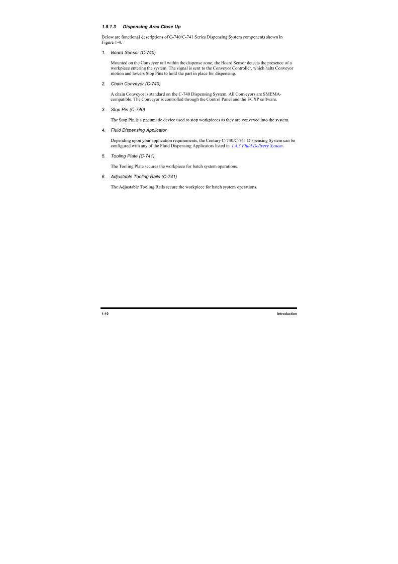
1.5.1.3 Dispensing Area Close Up
Below are functional descriptions of C-740/C-741 Series Dispensing System components shown in
Figure 1-4.
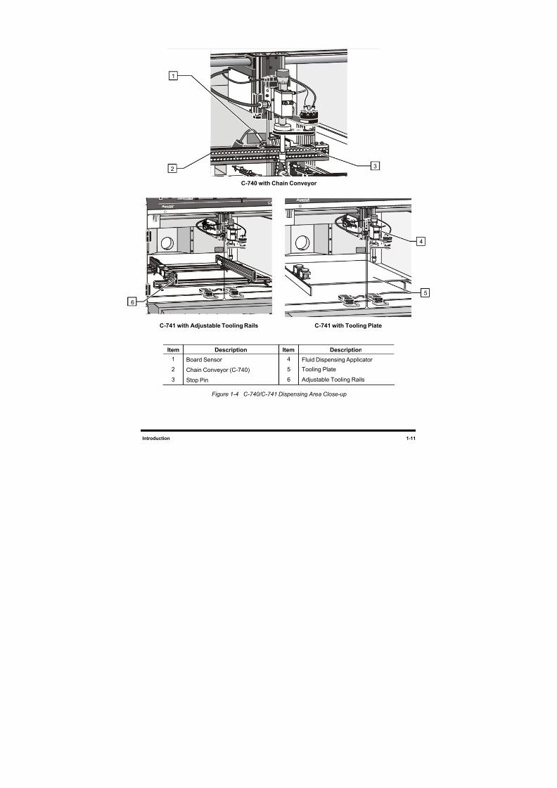
1. Board Sensor (C-740)
Mounted on the Conveyor rail within the dispense zone, the Board Sensor detects the presence of aworkpiece entering the system. The signal is sent to the Conveyor Controller, which halts Conveyor
motion and lowers Stop Pins to hold the part in place for dispensing.
2. Chain Conveyor (C-740)
A chain Conveyor is standard on the C-740 Dispensing System. All Conveyors are SMEMA-compatible. The Conveyor is controlled through the Control Panel and the ECXP software.
3. Stop Pin (C-740)
The Stop Pin is a pneumatic device used to stop workpieces as they are conveyed into the system.
4. Fluid Dispensing Applicator
Depending upon your application requirements, the Century C-740/C-741 Dispensing System can be
configured with any of the Fluid Dispensing Applicators listed in 1.4.3 Fluid Delivery System.
5. Tooling Plate (C-741)
The Tooling Plate secures the workpiece for batch system operations.
6. Adjustable Tooling Rails (C-741)
The Adjustable Tooling Rails secure the workpiece for batch system operations.
8/16/2019 Dispensig c 740 nordson
http://slidepdf.com/reader/full/dispensig-c-740-nordson 25/240
Introduction 1-11
C-740 with Chain Conveyor
C-741 with Adjustable Tooling Rails C-741 with Tooling Plate
Item Description Item Description
1 Board Sensor 4 Fluid Dispensing Applicator
2 Chain Conveyor (C-740) 5 Tooling Plate
3 Stop Pin 6 Adjustable Tooling Rails
Figure 1-4 C-740/C-741 Dispensing Area Close-up
1
2 3
4
5
6
8/16/2019 Dispensig c 740 nordson
http://slidepdf.com/reader/full/dispensig-c-740-nordson 26/240
1-12 Introduction
1.5.1.4 Lower Front Cabinet
Below are functional descriptions of C-740/C-741 Series Dispensing System components shown in
Figure 1-5.
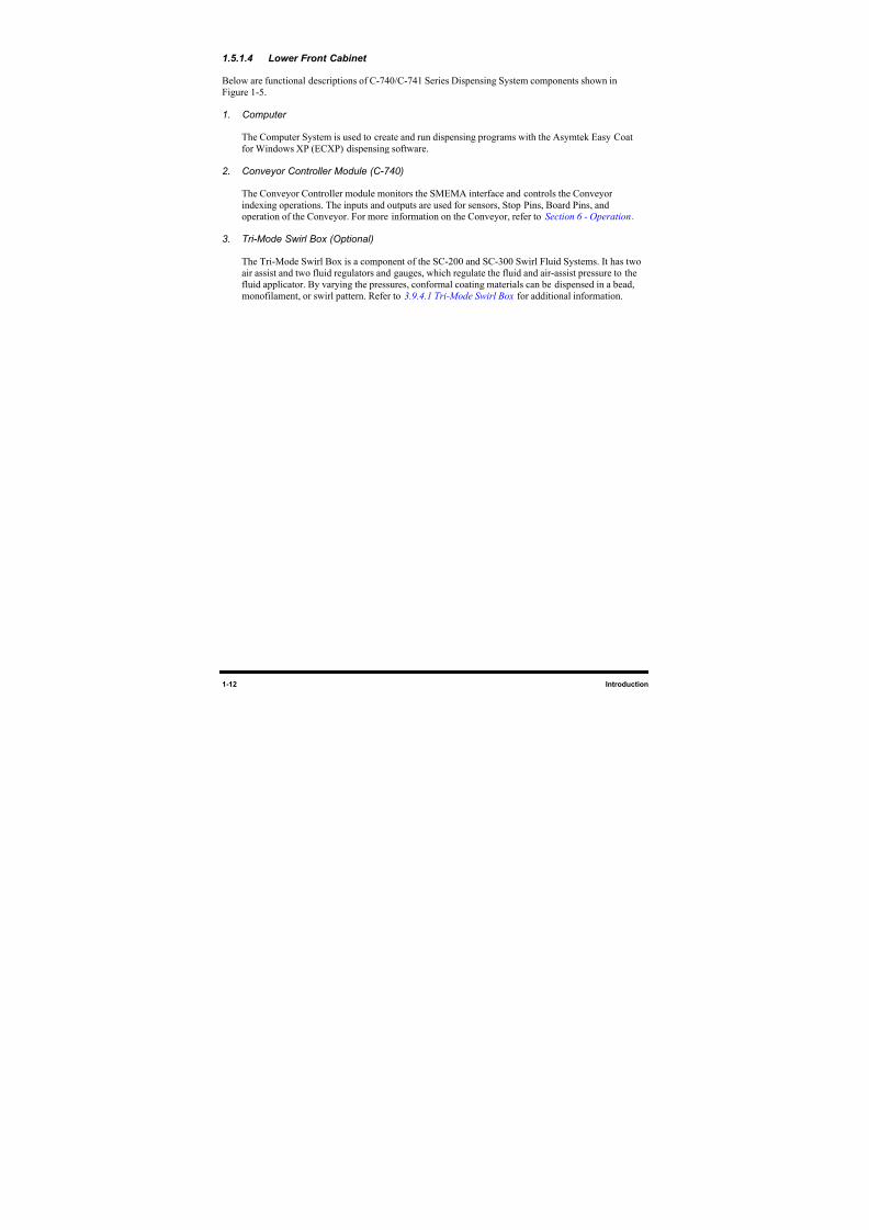
1. Computer
The Computer System is used to create and run dispensing programs with the Asymtek Easy Coatfor Windows XP (ECXP) dispensing software.
2. Conveyor Controller Module (C-740)
The Conveyor Controller module monitors the SMEMA interface and controls the Conveyor
indexing operations. The inputs and outputs are used for sensors, Stop Pins, Board Pins, andoperation of the Conveyor. For more information on the Conveyor, refer to Section 6 - Operation.
3. Tri-Mode Swirl Box (Optional)
The Tri-Mode Swirl Box is a component of the SC-200 and SC-300 Swirl Fluid Systems. It has two
air assist and two fluid regulators and gauges, which regulate the fluid and air-assist pressure to thefluid applicator. By varying the pressures, conformal coating materials can be dispensed in a bead,
monofilament, or swirl pattern. Refer to 3.9.4.1 Tri-Mode Swirl Box for additional information.
8/16/2019 Dispensig c 740 nordson
http://slidepdf.com/reader/full/dispensig-c-740-nordson 27/240
8/16/2019 Dispensig c 740 nordson
http://slidepdf.com/reader/full/dispensig-c-740-nordson 28/240
1-14 Introduction
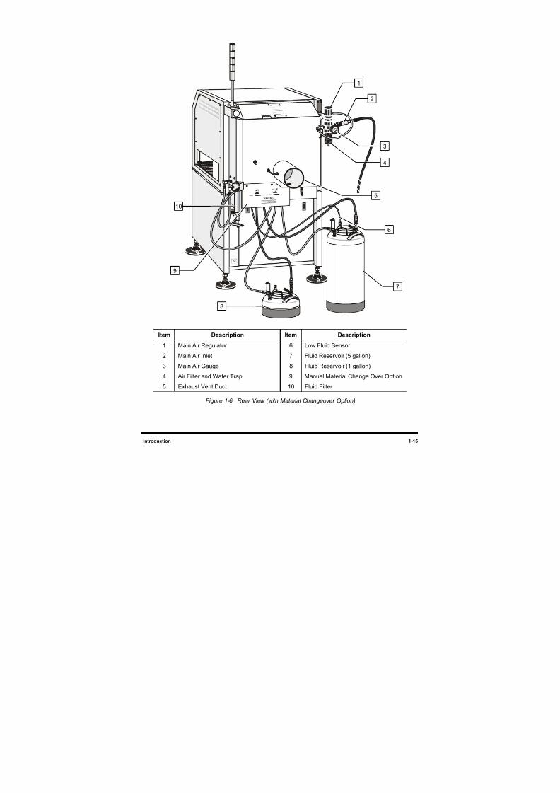
1.5.2 Rear View Features
Below are functional descriptions of C-740/C-741 Series Dispensing System components shown in
Figure 1-6.
1. Main Air Regulator
The Main Air Regulator controls air pressure supplied to the dispensing system through the Main AirInlet.
2. Main Air Inlet
The Main Air Inlet connects the Century Series Dispensing System to your facility air supply.
3. Main Air Gauge
The Main Air Gauge indicates the air pressure to which the Main Air Regulator is set. The
recommended setting is 551 to 620 kPa (80 to 90 psi).
4. Air Filter and Water Trap
The Air Filter and Water Trap remove particles and impurities in the facility air supply and are
contained in a single assembly.
5. Exhaust Vent Duct
The Exhaust Vent Duct removes fumes from the dispensing area. A customer-supplied air duct
must be connected from the dispensing system to the facility air ventilation system for the system
to operate.
6. Low Fluid Sensor (optional)
Located within the external reservoir, the Low Fluid Sensor triggers a Light Beacon display or
software error message when the level of coating material is low.
7. Fluid Reservoir - 5 gallon (optional)
The fluid reservoir contains conformal coating fluid or solvent.
8. Fluid Reservoir - 1 gallon
The fluid reservoir contains conformal coating fluid or solvent.
9. Manual Material Change Over (optional)
If your dispensing system is equipped with two fluid reservoirs, the Manual Material Change Over
mechanism is used to switch between a fluid reservoir and solvent reservoir and toggle the airsupplied between the reservoirs.
10. Fluid Filter
The Fluid Filter blocks small particles in the conformal coating fluid from passing to the Fluid
Dispensing Applicator.
8/16/2019 Dispensig c 740 nordson
http://slidepdf.com/reader/full/dispensig-c-740-nordson 29/240
Introduction 1-15
Item Description Item Description
1 Main Air Regulator 6 Low Fluid Sensor
2 Main Air Inlet 7 Fluid Reservoir (5 gallon)3 Main Air Gauge 8 Fluid Reservoir (1 gallon)
4 Air Filter and Water Trap 9 Manual Material Change Over Option
5 Exhaust Vent Duct 10 Fluid Filter
Figure 1-6 Rear View (with Material Changeover Option)
1
2
3
4
5
6
7
8
9
10
8/16/2019 Dispensig c 740 nordson
http://slidepdf.com/reader/full/dispensig-c-740-nordson 30/240
1-16 Introduction
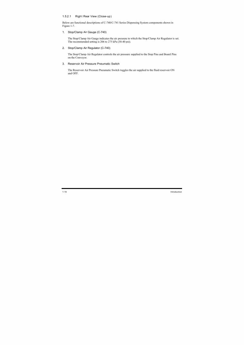
1.5.2.1 Right Rear View (Close-up)
Below are functional descriptions of C-740/C-741 Series Dispensing System components shown in
Figure 1-7.
1. Stop/Clamp Air Gauge (C-740)
The Stop/Clamp Air Gauge indicates the air pressure to which the Stop/Clamp Air Regulator is set.The recommended setting is 206 to 275 kPa (30-40 psi).
2. Stop/Clamp Air Regulator (C-740)
The Stop/Clamp Air Regulator controls the air pressure supplied to the Stop Pins and Board Pins
on the Conveyor.
3. Reservoir Air Pressure Pneumatic Switch
The Reservoir Air Pressure Pneumatic Switch toggles the air supplied to the fluid reservoir ON
and OFF.
8/16/2019 Dispensig c 740 nordson
http://slidepdf.com/reader/full/dispensig-c-740-nordson 31/240
Introduction 1-17
Item Description
1 Stop/Clamp Air Gauge
2 Stop/Clamp Air Regulator
3 Reservoir Air Pressure Pneumatic Switch
Figure 1-7 Right Rear Close-up
3
1
2
8/16/2019 Dispensig c 740 nordson
http://slidepdf.com/reader/full/dispensig-c-740-nordson 32/240
1-18 Introduction
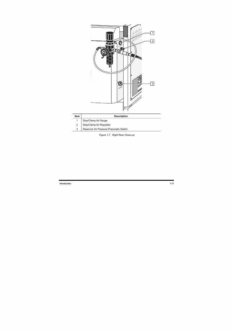
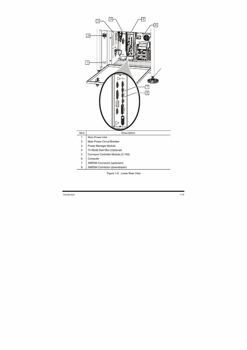
1.5.2.2 Lower Rear View
Below are functional descriptions of the C-740/C-741 Series Dispensing System components shown in
Figure 1-8.
1. Main Power Inlet
The Main Power Inlet connects the Main Power Cord from the facility power source to thedispensing system.
2. Main Power Circuit Breaker
The Main Power Circuit Breaker controls all electrical power to the entire system including the
dispensing system, Computer, and Computer Monitor.
3. Power Manager Module
The Power Manager Module controls both AC and DC power supplied to all system components.
4. Tri-Mode Swirl Box (Optional)
The Tri-Mode Swirl Box is a component of the SC-200 and SC-300 Swirl Fluid Systems. It has two
air assist and two fluid regulators and gauges, which regulate the fluid and air-assist pressure to the
fluid applicator. By varying the pressures, conformal coating materials can be dispensed in a bead,
monofilament, or swirl pattern. Refer to 3.9.4.1 Tri-Mode Swirl Box for additional information
5. Conveyor Controller Module (C-740)
The Conveyor Controller module monitors the SMEMA interface and controls the Conveyor
indexing operations. The inputs and outputs are used for sensors, Stop Pins, Board Pins, and
operation of the Conveyor. For more information on the Conveyor, refer to Section 6 - Operation.
6. Computer
The Computer System is used to create and run dispensing programs with the Asymtek Easy Coat
for Windows XP (ECXP) dispensing software.
7. SMEMA Connector (upstream)
The upstream SMEMA connector is located on the Conveyor Controller Module and allows for
SMEMA communication between the dispensing system and an upstream machine such as a loader.
8. SMEMA Connector (downstream)
The downstream SMEMA connector is located on the Conveyor Controller Module and allows forSMEMA communication between the dispensing system and a downstream machine such as an
unloader.
8/16/2019 Dispensig c 740 nordson
http://slidepdf.com/reader/full/dispensig-c-740-nordson 33/240
Introduction 1-19
Item Description
1 Main Power Inlet
2 Main Power Circuit Breaker
3 Power Manager Module
4 Tri-Mode Swirl Box (Optional)
5 Conveyor Controller Module (C-740)
6 Computer
7 SMEMA Connector (upstream)
8 SMEMA Connector (downstream)
Figure 1-8 Lower Rear View
5
6
1
43
2
7
8

8/16/2019 Dispensig c 740 nordson
http://slidepdf.com/reader/full/dispensig-c-740-nordson 34/240
8/16/2019 Dispensig c 740 nordson
http://slidepdf.com/reader/full/dispensig-c-740-nordson 35/240
Safety 2-1
2 Safety
2.1 Overview
This section is intended to provide basic safety information necessary for operating and servicing the
Century C-740/C-741 Series Dispensing System. This section covers the following topics:
Facility Requirements • Safety Warning Labels
Intended Use • Emergency Shutdown
Basic Safety Precautions and Practices • Lockout of Electrical and Pneumatic Energy
Laser Radiation • Integrated Safety Systems
Earthquake Precautions
To further optimize safe dispensing system operation, precautions and recommended practices are
included with the procedures throughout this manual.
WARNING! CAUTION! Unsafe equipment conditions can result in personal injury or property damage.Failure to properly operate and maintain the system in accordance with thismanual may compromise the built-in safety features.
NOTE Safety is considered a joint responsibility between the original equipment manufacturer(Asymtek) and the end-user (owner). All safety precautions and practices should be inaccordance with local regulations and facility practice.
2.2 Facility Requirements
To ensure optimal performance and safety, it is necessary to install the dispensing system in a facility that
meets the necessary requirements. See 11.3 Facility Requirements. If you have any questions, please
contact Asymtek Technical Support.
2.3 Intended Use
Use of Asymtek equipment in ways other than those described in the documentation supplied with the
equipment may result in injury to persons or damage to property. Some examples of unintended use of
equipment include:
• Using incompatible materials
• Making unauthorized modifications
• Removing or bypassing safety guards or interlocks
• Using incompatible or damaged parts
• Using unapproved auxiliary equipment
• Operating equipment in excess of maximum ratings
8/16/2019 Dispensig c 740 nordson
http://slidepdf.com/reader/full/dispensig-c-740-nordson 36/240
2-2 Safety
2.4 Basic Safety Precautions and Practices
Compliance with the following recommended precautions and practices will prevent personal injury or
damage to property during Century C-740/C-741 Series Dispensing System operation and maintenance.
WARNING! CAUTION!
Failure to comply with any of the safety recommendations could cause seriousinjury to the user or damage to the dispensing system.
2.4.1 Safety of Personnel
• Only trained personnel should be permitted to perform operation, maintenance, and
troubleshooting procedures.
• There should always be a second person present when performing maintenance on a system
under power.
• Locate, identify, and obey all safety warning labels on your system before initial use. See
2.7 Safety Warning Labels for details.
• Immediately push the red emergency machine off (EMO) button if personnel are in danger of
being injured.
• Lock out and tag out power and disconnect facility air to the dispensing system before
performing service or maintenance on the dispensing system. See 2.9 Lockout of Electrical
and Pneumatic Energy for details.
• Lock out and tag out power to upstream and downstream machines before performing service
or maintenance on the dispensing system.
• Do not wear loose clothing or jewelry while operating the system. Tie back long hair to
prevent it from being caught in moving parts.
• Do not touch the dispensing head, conveyor, or other moving parts while the dispensing
system is operating.
• To prevent burn injury, wear thermal gloves when working around heater tooling and fluid
heaters.
• If your system is equipped with Laser Fan Width Control, use extreme care to avoid looking
directly at the laser beam or its reflection off of mirror-like surfaces. See 2.5 Laser Radiation.
• Always wear appropriate personal protective equipment (PPE) as recommended by facility
safety practices and the material manufacturer’s Material Safety Data Sheet (MSDS).
• Make sure that the main power cable and main air supply hose are securely connected before
operating the dispensing system.
• If in a confined room, ensure adequate and uninterrupted air ventilation, heating, and cooling
to meet environmental stress limits of personnel and the dispensing system.
8/16/2019 Dispensig c 740 nordson
http://slidepdf.com/reader/full/dispensig-c-740-nordson 37/240
Safety 2-3
• Where volatile organic compound (VOC) emissions can exceed safe limits, facility
ventilation and filtration systems must be operational.
• Provide adequate space around the dispensing system to allow for movement of maintenance
and service personnel. Allow space for access doors and service panels to open fully.
• Make sure all facility power sources are safely grounded.
• Routinely inspect all air hoses and electrical cables for damage.
• Make sure that power cords and air supply hoses do not cross a walkway or aisle.
• Before attempting to lift a load, take into consideration facility lifting and transport
precautions.
• Maintain a clean and orderly work area.
2.4.2 Material Safety
• Follow Material Safety Data Sheet (MSDS) recommendations for the proper handling,cleanup, and disposal of hazardous materials.
• Know the MSDS recommendations for treatment of injury resulting from exposure to
hazardous materials. See 2.4.4 High-Pressure Fluids.
• When working with multiple fluids, refer to the MSDS to ensure the materials are
compatible.
2.4.3 Preventing Dispensing System and Workpiece Damage
• Immediately push the EMO button if dispensing system or a workpiece is in danger of
being damaged.
• Use standard Electrostatic Discharge (ESD) precautions when working near sensitive
components. Always wear a grounding strap and connect it to the ESD ground before
handling workpieces.
• Immediately contain and clean up any caustic or conductive fluid spills as recommended in
the material manufacturer’s MSDS. If fluid gets into internal portions of the machine,
immediately contact Asymtek Technical Support.
• Follow all recommended system maintenance procedures.
• Always keep the dispensing area clear of any fallen workpieces or obstacles.
• Ensure that no air intake or exhaust grilles are blocked when the system is in operation.
8/16/2019 Dispensig c 740 nordson
http://slidepdf.com/reader/full/dispensig-c-740-nordson 38/240
2-4 Safety
2.4.4 High-Pressure Fluids
High-pressure fluids, unless they are safely contained, are extremely hazardous. Always relieve fluid
pressure before adjusting or servicing high-pressure equipment. A jet of high-pressure fluid can cut like a
knife and cause serious bodily injury, amputation, or death. Fluids penetrating the skin can also cause
toxic poisoning.
If you suffer a fluid injection injury, seek medical care immediately. If possible, provide a copy of theMSDS for the injected fluid to the health care provider.
The National Spray Equipment Manufacturers Association has created a wallet card that you should carry
when you are operating high-pressure spray equipment. These cards are supplied with your equipment.
The following is the text of this card:
WARNING: Any injury caused by high-pressure liquid can be serious. If you are injured oreven suspect an injury:
• Go to an emergency room immediately.
• Tell the physician that you suspect an injection injury.
• Show the physician this card.
• Tell the physician what kind of material you were spraying.
MEDICAL ALERT – AIRLESS SPRAY WOUNDS: NOTE TO PHYSICIAN
Injection in the skin is a serious traumatic injury. It is important to treat the injurysurgically as soon as possible. Do not delay treatment to research toxicity. Toxicity isa concern with some exotic coatings injected directly into the bloodstream.
Consultation with a plastic surgeon or a reconstructive hand surgeon may beadvisable.
The seriousness of the wound depends on where the injury is on the body, whetherthe substance hit something on its way in and deflected causing more damage, andmany other variables including skin microflora residing in the paint or gun, which areblasted into the wound. If the injected paint contains acrylic latex and titanium dioxidethat damage the tissue’s resistance to infection, bacterial growth will flourish. Thetreatment that doctors recommend for an injection injury to the hand includesimmediate decompression of the closed vascular compartments of the hand torelease the underlying tissue distended by the injected paint, judicious wounddepravement, and immediate antibiotic treatment.

8/16/2019 Dispensig c 740 nordson
http://slidepdf.com/reader/full/dispensig-c-740-nordson 39/240
Safety 2-5
2.5 Laser Radiation
The optional Laser Fan Width Control uses a Class II laser sensor. The following safety precautions
should be observed in addition to the standard coating system safety precautions.
• Operate the Laser Fan Width Control only according to the procedures described in the
instructions included. Failure to do so may result in injury due to exposure to the laser beam.
• DO NOT look directly at the laser beam.
WARNING ! Looking directly at the laser beam may result in serious eye injury.
NOTE The laser beam is not harmful to the skin. There is no danger in exposing arms or handsto the beam. The only possible health hazard is in exposing the eyes to the laser beam.
Table 2-1 Laser Fan Width Control Specifications
ORGANIZATION CLASSIFICATIONFDA CLASS II
IEC 60825-1 1998-01 CLASS 2
DIN EN 60825-1 1998-01 KLASSE 2
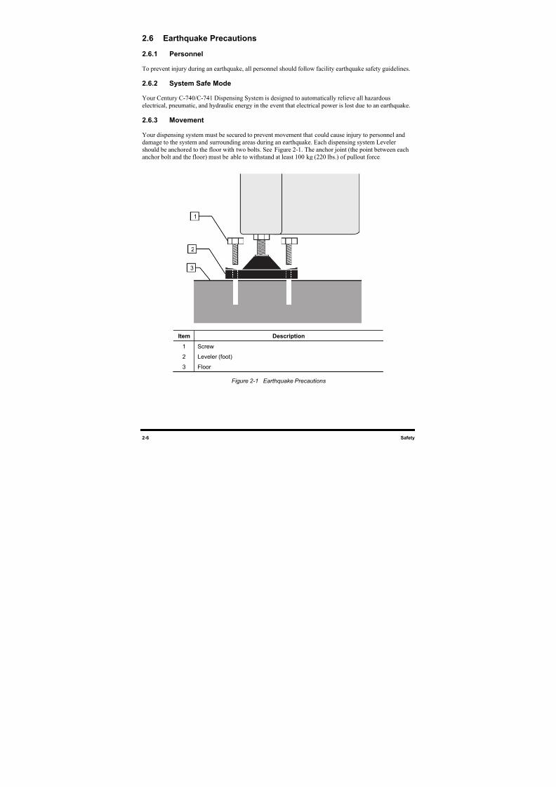
8/16/2019 Dispensig c 740 nordson
http://slidepdf.com/reader/full/dispensig-c-740-nordson 40/240
2-6 Safety
2.6 Earthquake Precautions
2.6.1 Personnel
To prevent injury during an earthquake, all personnel should follow facility earthquake safety guidelines.
2.6.2 System Safe Mode
Your Century C-740/C-741 Dispensing System is designed to automatically relieve all hazardous
electrical, pneumatic, and hydraulic energy in the event that electrical power is lost due to an earthquake.
2.6.3 Movement
Your dispensing system must be secured to prevent movement that could cause injury to personnel and
damage to the system and surrounding areas during an earthquake. Each dispensing system Leveler
should be anchored to the floor with two bolts. See Figure 2-1. The anchor joint (the point between each
anchor bolt and the floor) must be able to withstand at least 100 kg (220 lbs.) of pullout force.
Item Description
1 Screw
2 Leveler (foot)
3 Floor
Figure 2-1 Earthquake Precautions
1
2
3
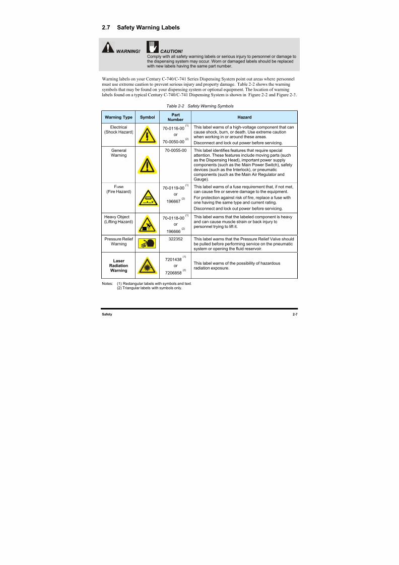
8/16/2019 Dispensig c 740 nordson
http://slidepdf.com/reader/full/dispensig-c-740-nordson 41/240
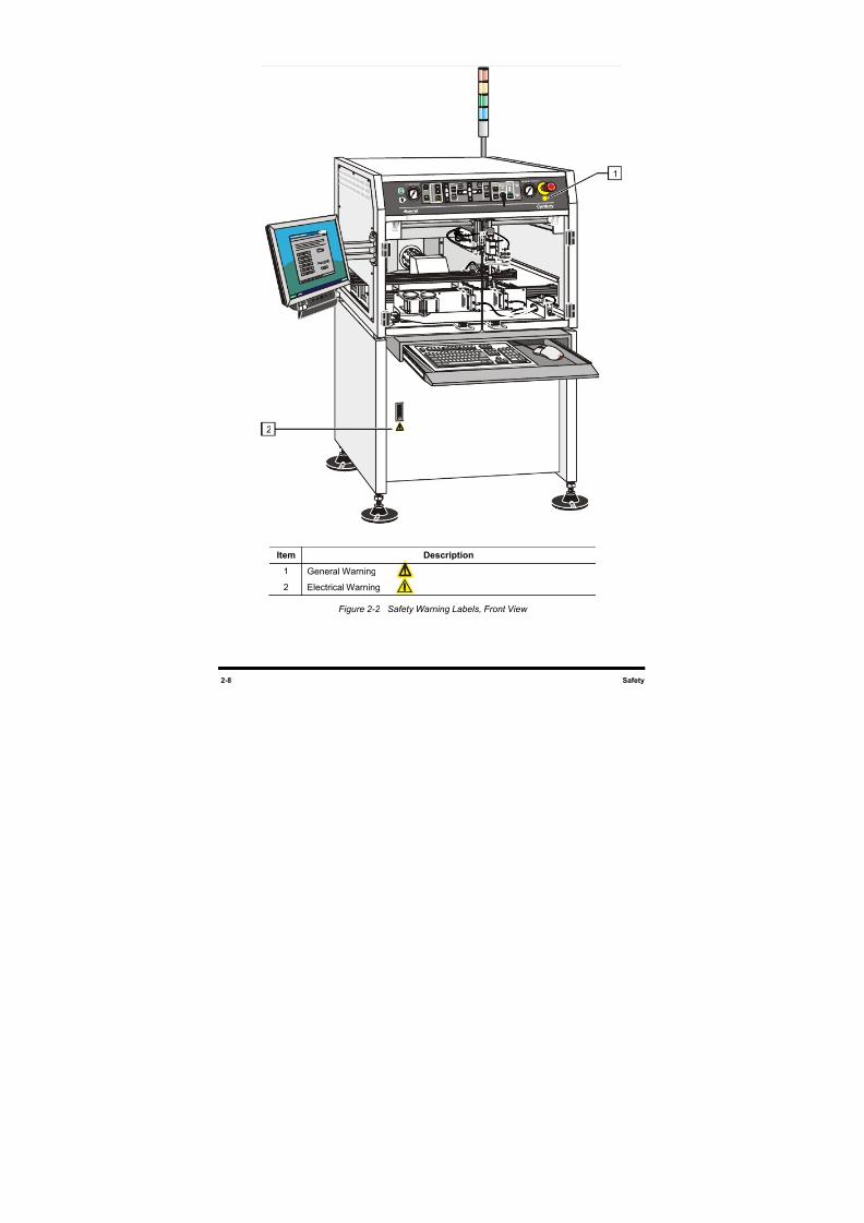
8/16/2019 Dispensig c 740 nordson
http://slidepdf.com/reader/full/dispensig-c-740-nordson 42/240
2-8 Safety
Item Description
1 General Warning
2 Electrical Warning
Figure 2-2 Safety Warning Labels, Front View
1
2
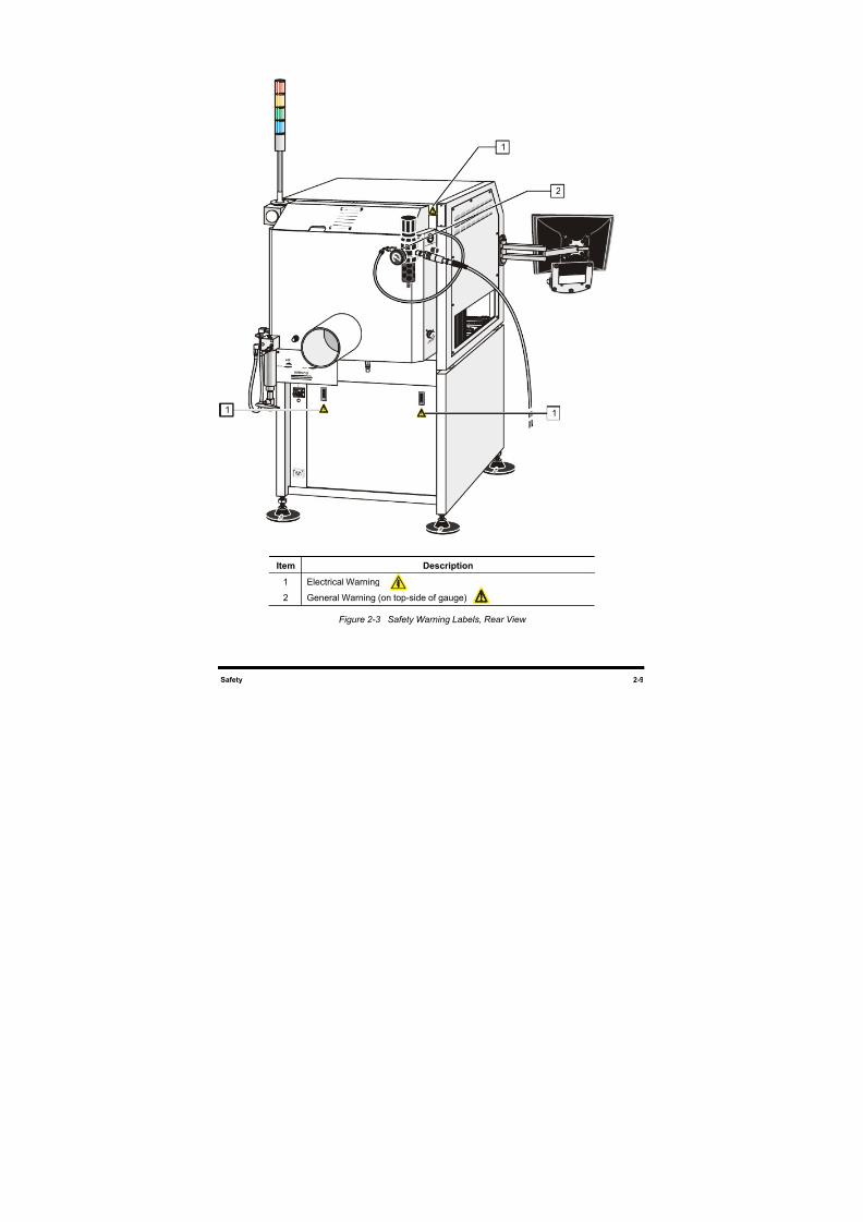
8/16/2019 Dispensig c 740 nordson
http://slidepdf.com/reader/full/dispensig-c-740-nordson 43/240
Safety 2-9
Item Description
1 Electrical Warning
2 General Warning (on top-side of gauge)
Figure 2-3 Safety Warning Labels, Rear View
2
1
1 1
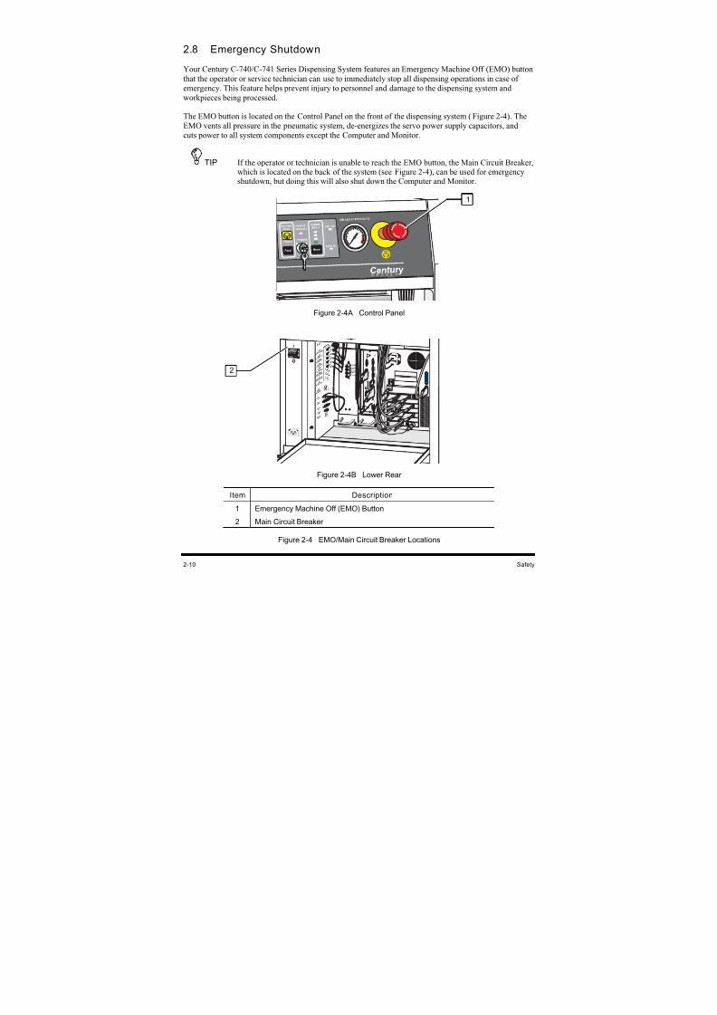
8/16/2019 Dispensig c 740 nordson
http://slidepdf.com/reader/full/dispensig-c-740-nordson 44/240
2-10 Safety
2.8 Emergency Shutdown
Your Century C-740/C-741 Series Dispensing System features an Emergency Machine Off (EMO) button
that the operator or service technician can use to immediately stop all dispensing operations in case of
emergency. This feature helps prevent injury to personnel and damage to the dispensing system and
workpieces being processed.
The EMO button is located on the Control Panel on the front of the dispensing system (Figure 2-4). TheEMO vents all pressure in the pneumatic system, de-energizes the servo power supply capacitors, and
cuts power to all system components except the Computer and Monitor.
TIP If the operator or technician is unable to reach the EMO button, the Main Circuit Breaker,which is located on the back of the system (see Figure 2-4), can be used for emergencyshutdown, but doing this will also shut down the Computer and Monitor.
Figure 2-4A Control Panel
Figure 2-4B Lower Rear
Item Description
1 Emergency Machine Off (EMO) Button
2 Main Circuit Breaker
Figure 2-4 EMO/Main Circuit Breaker Locations
1
2
1
8/16/2019 Dispensig c 740 nordson
http://slidepdf.com/reader/full/dispensig-c-740-nordson 45/240
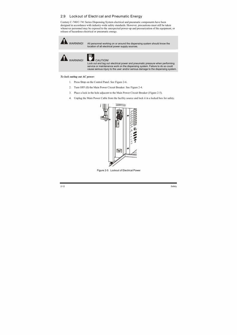
8/16/2019 Dispensig c 740 nordson
http://slidepdf.com/reader/full/dispensig-c-740-nordson 46/240
2-12 Safety
2.9 Lockout of Electrical and Pneumatic Energy
Century C-740/C-741 Series Dispensing System electrical and pneumatic components have been
designed in accordance with industry-wide safety standards. However, precautions must still be taken
whenever personnel may be exposed to the unexpected power-up and pressurization of the equipment, or
release of hazardous electrical or pneumatic energy.
WARNING! All personnel working on or around the dispensing system should know thelocation of all electrical power supply sources.
WARNING! CAUTION!
Lock out and tag out electrical power and pneumatic pressure when performingservice or maintenance work on the dispensing system. Failure to do so couldcause serious injury to the user and/or serious damage to the dispensing system.
To lock out/tag out AC power:
1. Press Stop on the Control Panel. See Figure 2-6.
2. Turn OFF (0) the Main Power Circuit Breaker. See Figure 2-4.
3. Place a lock in the hole adjacent to the Main Power Circuit Breaker (Figure 2-5).
4. Unplug the Main Power Cable from the facility source and lock it in a locked box for safety.
Figure 2-5 Lockout of Electrical Power
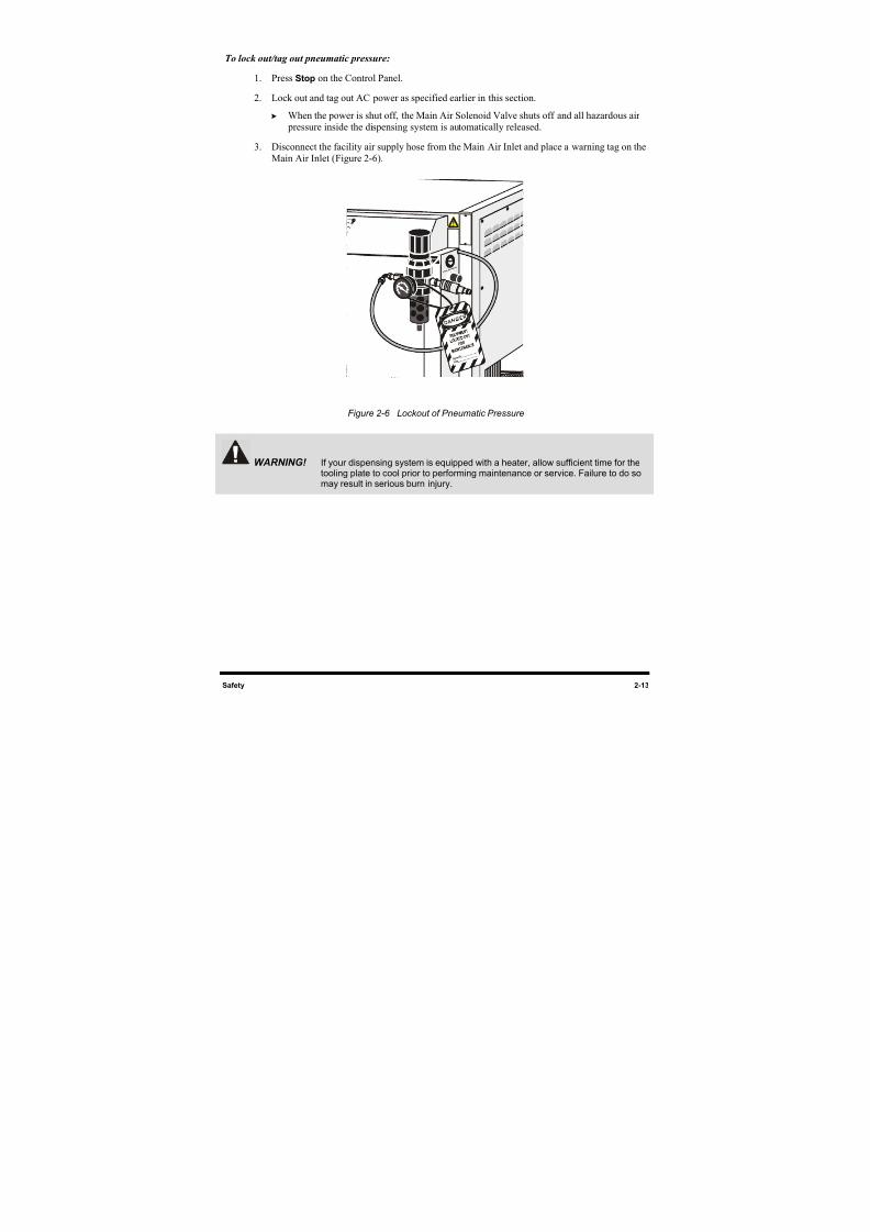
8/16/2019 Dispensig c 740 nordson
http://slidepdf.com/reader/full/dispensig-c-740-nordson 47/240
Safety 2-13
To lock out/tag out pneumatic pressure:
1. Press Stop on the Control Panel.
2. Lock out and tag out AC power as specified earlier in this section.
When the power is shut off, the Main Air Solenoid Valve shuts off and all hazardous air
pressure inside the dispensing system is automatically released.
3. Disconnect the facility air supply hose from the Main Air Inlet and place a warning tag on the
Main Air Inlet (Figure 2-6).
Figure 2-6 Lockout of Pneumatic Pressure
WARNING! If your dispensing system is equipped with a heater, allow sufficient time for thetooling plate to cool prior to performing maintenance or service. Failure to do somay result in serious burn injury.
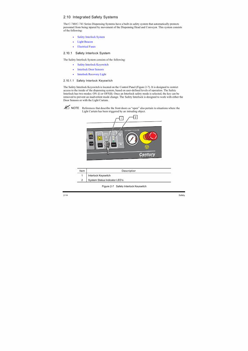
8/16/2019 Dispensig c 740 nordson
http://slidepdf.com/reader/full/dispensig-c-740-nordson 48/240
2-14 Safety
2.10 Integrated Safety Systems
The C-740/C-741 Series Dispensing Systems have a built-in safety system that automatically protects
personnel from being injured by movement of the Dispensing Head and Conveyor. This system consists
of the following:
• Safety Interlock System
• Light Beacon
• Electrical Fuses
2.10.1 Safety Interlock System
The Safety Interlock System consists of the following:
• Safety Interlock Keyswitch
• Interlock Door Sensors
• Interlock Recovery Light
2.10.1.1 Safety Interlock Keyswi tch
The Safety Interlock Keyswitch is located on the Control Panel (Figure 2-7). It is designed to restrict
access to the inside of the dispensing system, based on user-defined levels of operation. The Safety
Interlock has two modes: ON (l) or OFF(0). Once an Interlock safety mode is selected, the key can be
removed to prevent an inadvertent mode change. The Safety Interlock is designed to work with either the
Door Sensors or with the Light Curtain.
NOTE References that describe the front doors as “open” also pertain to situations where theLight Curtain has been triggered by an intruding object.
Item Description
1 Interlock Keyswitch
2 System Status Indicator LED’s
Figure 2-7 Safety Interlock Keyswitch
12
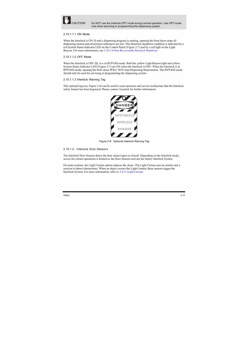
8/16/2019 Dispensig c 740 nordson
http://slidepdf.com/reader/full/dispensig-c-740-nordson 49/240
Safety 2-15
CAUTION! Do NOT use the Interlock OFF mode during normal operation. Use OFF modeonly when servicing or programming the dispensing system.
2.10.1.1.1 ON Mode
When the Interlock is ON (I) and a dispensing program is running, opening the front doors stops alldispensing motion and all position references are lost. This Interlock shutdown condition is indicated by a
red System Status Indicator LED on the Control Panel (Figure 2-7) and by a red light on the Light
Beacon. For more information, see 2.10.1.4 Non-Recoverable Interlock Shutdown.
2.10.1.1.2 OFF Mode
When the Interlock is OFF (0), it is in BYPASS mode. Both the yellow Light Beacon light and yellow
System Status Indicator LED (Figure 2-7) are ON when the Interlock is OFF. When the Interlock is in
BYPASS mode, opening the front doors WILL NOT stop Dispensing Head motion. The BYPASS mode
should only be used for servicing or programming the dispensing system.
2.10.1.1.3 Interlock Warning Tag
This optional tag (see Figure 2-8) can be used to warn operators and service technicians that the Interlock
safety feature has been bypassed. Please contact Asymtek for further information.
DANGER
S A F E T Y S H I E L D
I N T E R L O C K
B Y P A S S E D
Figure 2-8 Optional Interlock Warning Tag
2.10.1.2 Interlock Door Sensors
The Interlock Door Sensors detect the door status (open or closed). Depending on the Interlock mode,
access for certain operations is limited as the Door Sensors activate the Safety Interlock System.
On some systems, the Light Curtain option replaces the doors. The Light Curtain uses an emitter and a
receiver to detect obstructions. When an object crosses the Light Curtain, these sensors trigger the
Interlock System. For more information, refer to 3.8.11 Light Curtain.
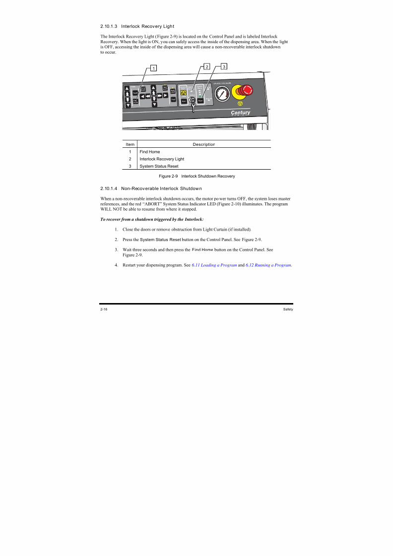
8/16/2019 Dispensig c 740 nordson
http://slidepdf.com/reader/full/dispensig-c-740-nordson 50/240
2-16 Safety
2.10.1.3 Interlock Recovery Light
The Interlock Recovery Light (Figure 2-9) is located on the Control Panel and is labeled Interlock
Recovery. When the light is ON, you can safely access the inside of the dispensing area. When the lightis OFF, accessing the inside of the dispensing area will cause a non-recoverable interlock shutdown
to occur.
Item Description
1 Find Home
2 Interlock Recovery Light
3 System Status Reset
Figure 2-9 Interlock Shutdown Recovery
2.10.1.4 Non-Recoverable Interlock Shutdown
When a non-recoverable interlock shutdown occurs, the motor power turns OFF, the system loses master
references, and the red “ABORT” System Status Indicator LED (Figure 2-10) illuminates. The program
WILL NOT be able to resume from where it stopped.
To recover from a shutdown triggered by the Interlock:
1. Close the doors or remove obstruction from Light Curtain (if installed).
2. Press the System Status Reset button on the Control Panel. See Figure 2-9.
3. Wait three seconds and then press the Find Home button on the Control Panel. SeeFigure 2-9.
4. Restart your dispensing program. See 6.11 Loading a Program and 6.12 Running a Program.
1 2 3
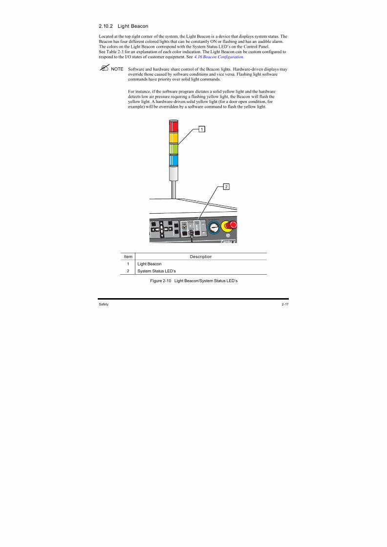
8/16/2019 Dispensig c 740 nordson
http://slidepdf.com/reader/full/dispensig-c-740-nordson 51/240
Safety 2-17
2.10.2 Light Beacon
Located at the top right corner of the system, the Light Beacon is a device that displays system status. The
Beacon has four different colored lights that can be constantly ON or flashing and has an audible alarm.
The colors on the Light Beacon correspond with the System Status LED’s on the Control Panel.
See Table 2-3 for an explanation of each color indication. The Light Beacon can be custom configured to
respond to the I/O states of customer equipment. See 4.16 Beacon Configuration.
NOTE Software and hardware share control of the Beacon lights. Hardware-driven displays mayoverride those caused by software conditions and vice versa. Flashing light softwarecommands have priority over solid light commands.
For instance, if the software program dictates a solid yellow light and the hardwaredetects low air pressure requiring a flashing yellow light, the Beacon will flash theyellow light. A hardware-driven solid yellow light (for a door open condition, forexample) will be overridden by a software command to flash the yellow light.
r
Inter lock
Inter lock
Recover y System
Status Vent Air
Main Air
Air Assist Pr essur e
Reset
Pause
Convey or Status
Reset
Conv y r Robot
Appli c
P ur ge
Enable Enable
On / Off
Item Description
1 Light Beacon
2 System Status LED’s
Figure 2-10 Light Beacon/System Status LED’s
1
2
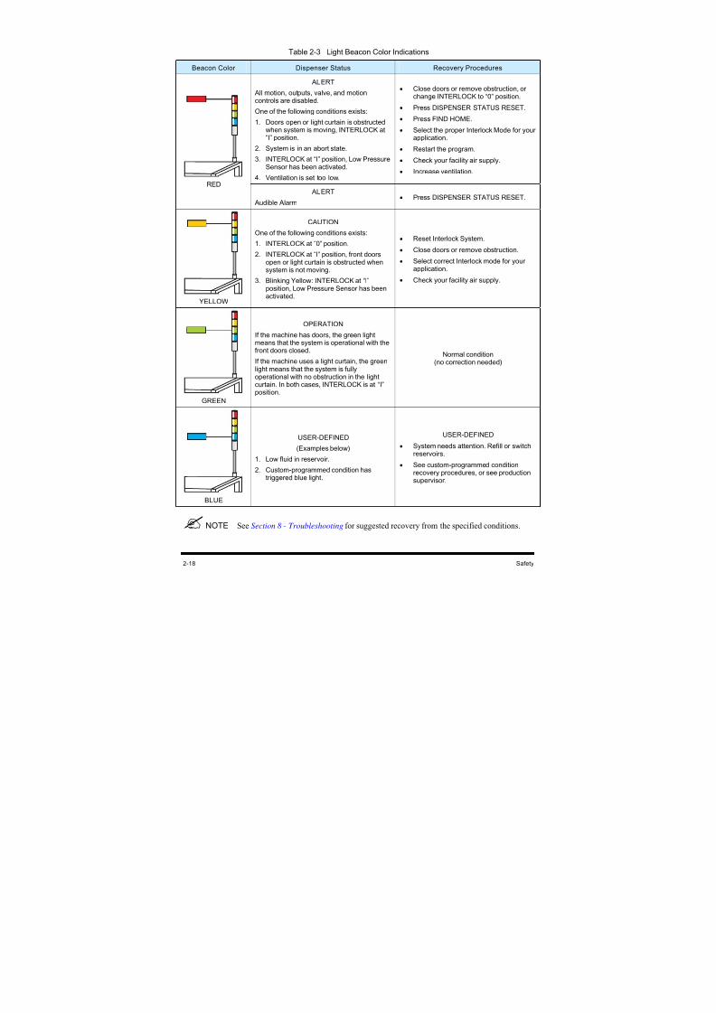
8/16/2019 Dispensig c 740 nordson
http://slidepdf.com/reader/full/dispensig-c-740-nordson 52/240
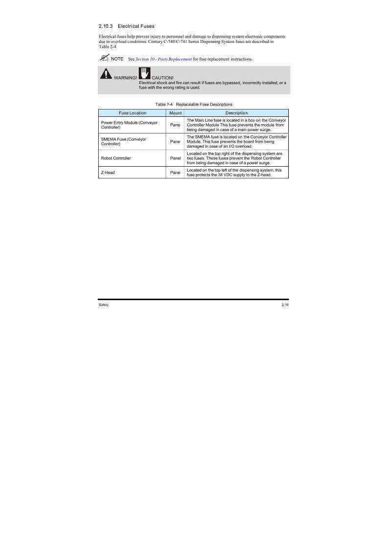
8/16/2019 Dispensig c 740 nordson
http://slidepdf.com/reader/full/dispensig-c-740-nordson 53/240
Safety 2-19
2.10.3 Electrical Fuses
Electrical fuses help prevent injury to personnel and damage to dispensing system electronic components
due to overload conditions. Century C-740/C-741 Series Dispensing System fuses are described in
Table 2-4.
NOTE See Section 10 - Parts Replacement for fuse replacement instructions.
WARNING! CAUTION! Electrical shock and fire can result if fuses are bypassed, incorrectly installed, or afuse with the wrong rating is used.
Table 2-4 Replaceable Fuse Descriptions
Fuse Location Mount Description
Power Entry Module (ConveyorController) Panel
The Main Line fuse is located in a box on the Conveyor
Controller Module This fuse prevents the module frombeing damaged in case of a main power surge.
SMEMA Fuse (ConveyorController)
PanelThe SMEMA fuse is located on the Conveyor ControllerModule. This fuse prevents the board from beingdamaged in case of an I/O overload.
Robot Controller PanelLocated on the top right of the dispensing system aretwo fuses. These fuses prevent the Robot Controllerfrom being damaged in case of a power surge.
Z-Head PanelLocated on the top left of the dispensing system, thisfuse protects the 38 VDC supply to the Z-head.

8/16/2019 Dispensig c 740 nordson
http://slidepdf.com/reader/full/dispensig-c-740-nordson 54/240
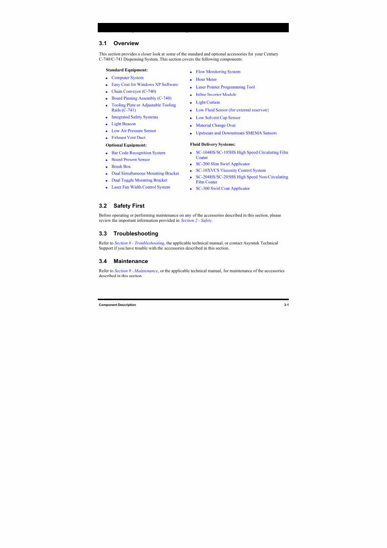
8/16/2019 Dispensig c 740 nordson
http://slidepdf.com/reader/full/dispensig-c-740-nordson 55/240
8/16/2019 Dispensig c 740 nordson
http://slidepdf.com/reader/full/dispensig-c-740-nordson 56/240
3-2 Component Description
3.5 Specifications
Refer to Section 11 - Specifications or the applicable technical manual, for performance specifications of
the accessories described in this section.
3.6 Testing
Functional testing of the component should be performed only by a trained service technician in
accordance with the procedures in Section 5 - Power-up and Testing or in the applicable OEM technical
manual.
8/16/2019 Dispensig c 740 nordson
http://slidepdf.com/reader/full/dispensig-c-740-nordson 57/240
Component Description 3-3
3.7 Standard Components
3.7.1 Computer System
The Computer system consists of the Computer, Monitor, Keyboard and Mouse. It runs Easy Coat for
Windows XP (ECXP) software.
3.7.2 Easy Coat for Windows XP Software
Easy Coat for Windows XP (ECXP) is Asymtek proprietary software for use in a Windows XP
environment, developed specifically for Conformal Coating applications. ECXP controls both the
Dispensing Head (Robot) movements and the dispensing operation. ECXP features include:
• Internationalization
• Off-Line Programming
• Multiple Tool Selection
• Position Detection
3.7.3 Chain Conveyor (C-740)
The chain Conveyor, standard on the Century Series C-740 Dispensing System, transports the workpiece
into and out of the dispensing system. Operation of the Conveyor is automatic during production runs.
See Figure 1-4.
3.7.4 Board Pinning Assembly (C-740)
The Board Pinning Assembly features a Board Pinning Sensor and locates the board in terms of X/Y
location and rotation.
3.7.5 Tooling Plate or Adjustable Tooling Rails (C-741)
The Tooling Plate or Adjustable Tooling Rails secures the workpiece for batch system operations.
See Figure 1-4.
3.7.6 Integrated Safety Systems
The C-740/C-741 Series Dispensing Systems have a built-in safety system that automatically prevents
injury and damage resulting from Dispensing Head and Conveyor movement. The Integrated Safety
Systems consist of an Interlock Keyswitch, Interlock Door Sensors, an Interlock Recovery Light, StatusIndicator Lights, and a Light Beacon.
The Interlock Door Sensors detect if the dispensing area doors are open or closed. When the Interlock
Keyswitch is in the ON (I) position and a dispensing program is running, opening the front doors stops all
dispensing motion. This interlock shutdown condition is indicated by a red Status Indicator Light on the
Control Panel and by a red light on the Light Beacon.
NOTE References that describe the front doors as “open” also pertain to situations where theLight Curtain has been triggered by an intruding object.
8/16/2019 Dispensig c 740 nordson
http://slidepdf.com/reader/full/dispensig-c-740-nordson 58/240
3-4 Component Description
When the Keyswitch is in the OFF (0) position, the yellow Beacon light is ON and the Interlock Recovery
Light is ON. Opening the Dispensing Area Doors in this state does not disable the dispensing system
motion controls.
The Interlock Key can be removed to prevent an inadvertent mode change. See 2.10 Integrated Safety
Systems for additional information.
CAUTION! Do NOT use the Interlock OFF mode during normal operation. Use the OFF mode only when servicing or programming the dispensing system.
3.7.7 Light Beacon
The Light Beacon is a device that displays system status and is located at the top right corner of the
system. It has four different colored lights that can be constantly ON or flashing and has an audible alarm.
Refer to 2.10.4 Light Beacon for an explanation of each color indication.
3.7.8 Low Air Pressure Sensor
The Low Air Pressure Sensor is connected to the Main Air Inlet. If the pressure drops below a set point, ittriggers the dispensing system Safety Interlock. This feature is used to alert the operator of pressure drop
conditions that may occur in large facilities with a number of pneumatic devices.
3.7.9 Exhaust Vent Duct
The Exhaust Vent Duct (Figure 1-6) removes fumes from the dispensing area. A customer supplied air
duct must be connected from the dispensing system to the facility air exhaust system for the system to
operate. Refer to 4.11 Exhaust Connection.
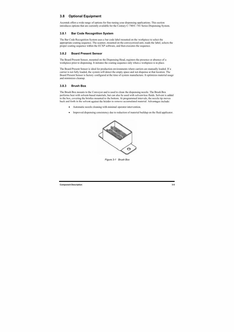
8/16/2019 Dispensig c 740 nordson
http://slidepdf.com/reader/full/dispensig-c-740-nordson 59/240
Component Description 3-5
3.8 Optional Equipment
Asymtek offers a wide range of options for fine-tuning your dispensing applications. This section
introduces options that are currently available for the Century C-740/C-741 Series Dispensing System.
3.8.1 Bar Code Recognition System
The Bar Code Recognition System uses a bar code label mounted on the workpiece to select the
appropriate coating sequence. The scanner, mounted on the conveyorized unit, reads the label, selects the
proper coating sequence within the ECXP software, and then executes the sequence.
3.8.2 Board Present Sensor
The Board Present Sensor, mounted on the Dispensing Head, registers the presence or absence of a
workpiece prior to dispensing. It initiates the coating sequence only when a workpiece is in place.
The Board Present Sensor is ideal for production environments where carriers are manually loaded. If a
carrier is not fully loaded, the system will detect the empty space and not dispense at that location. The
Board Present Sensor is factory configured at the time of system manufacture. It optimizes material usageand minimizes cleanup.
3.8.3 Brush Box
The Brush Box mounts to the Conveyor and is used to clean the dispensing nozzle. The Brush Box
performs best with solvent-based materials, but can also be used with solvent-less fluids. Solvent is added
to the box, covering the bristles mounted to the bottom. At programmed intervals, the nozzle tip moves
back and forth in the solvent against the bristles to remove accumulated material. Advantages include:
• Automatic nozzle cleaning with minimal operator intervention.
• Improved dispensing consistency due to reduction of material buildup on the fluid applicator.
Figure 3-1 Brush Box
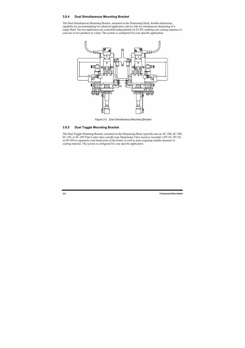
8/16/2019 Dispensig c 740 nordson
http://slidepdf.com/reader/full/dispensig-c-740-nordson 60/240
3-6 Component Description
3.8.4 Dual Simultaneous Mounting Bracket
The Dual Simultaneous Mounting Bracket, mounted on the Dispensing Head, doubles dispensing
capability by accommodating two identical applicators side by side for simultaneous dispensing of a
single fluid. The two applicators are controlled independently by ECXP, enabling one coating sequence to
coat one or two products at a time. The system is configured for your specific application.
Figure 3-2 Dual Simultaneous Mounting Bracket
3.8.5 Dual Toggle Mounting Bracket
The Dual Toggle Mounting Bracket, mounted on the Dispensing Head, typically uses an SC-200, SC-300,
SC-105, or SC-205 Film Coater plus a needle type Dispensing Valve (such as Asymtek’s DV-03, DV-05,
or DV-09) to separately coat broad areas of the board, as well as areas requiring smaller amounts of
coating material. The system is configured for your specific application.
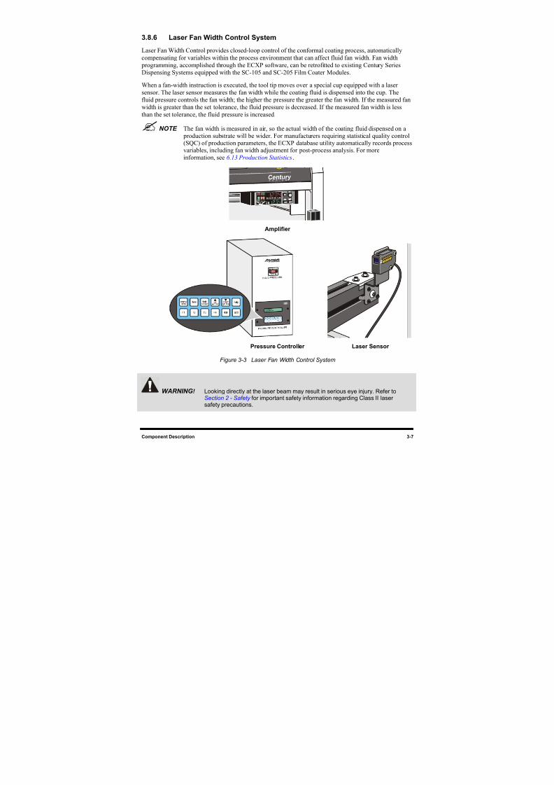
8/16/2019 Dispensig c 740 nordson
http://slidepdf.com/reader/full/dispensig-c-740-nordson 61/240
Component Description 3-7
3.8.6 Laser Fan Width Control System
Laser Fan Width Control provides closed-loop control of the conformal coating process, automatically
compensating for variables within the process environment that can affect fluid fan width. Fan width
programming, accomplished through the ECXP software, can be retrofitted to existing Century Series
Dispensing Systems equipped with the SC-105 and SC-205 Film Coater Modules.
When a fan-width instruction is executed, the tool tip moves over a special cup equipped with a laser
sensor. The laser sensor measures the fan width while the coating fluid is dispensed into the cup. The
fluid pressure controls the fan width; the higher the pressure the greater the fan width. If the measured fan
width is greater than the set tolerance, the fluid pressure is decreased. If the measured fan width is less
than the set tolerance, the fluid pressure is increased.
NOTE The fan width is measured in air, so the actual width of the coating fluid dispensed on a production substrate will be wider. For manufacturers requiring statistical quality control(SQC) of production parameters, the ECXP database utility automatically records processvariables, including fan width adjustment for post-process analysis. For moreinformation, see 6.13 Production Statistics.
Amplifier
Pressure Controller Laser Sensor
Figure 3-3 Laser Fan Width Control System
WARNING ! Looking directly at the laser beam may result in serious eye injury. Refer toSection 2 - Safety for important safety information regarding Class II lasersafety precautions.
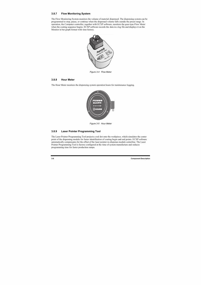
8/16/2019 Dispensig c 740 nordson
http://slidepdf.com/reader/full/dispensig-c-740-nordson 62/240
3-8 Component Description
3.8.7 Flow Monitoring System
The Flow Monitoring System monitors the volume of material dispensed. The dispensing system can be
programmed to stop, pause, or continue when the dispensed volume falls outside the preset range. In
operation, the Computer controller, together with ECXP software, monitors the gear-type Flow Meter
when the coating sequence begins. ECXP software records the data in a log file and displays it on the
Monitor in bar graph format with time history.
Figure 3-4 Flow Meter
3.8.8 Hour Meter
The Hour Meter monitors the dispensing system operation hours for maintenance logging.
Figure 3-5 Hour Meter
3.8.9 Laser Pointer Programming Tool
The Laser Pointer Programming Tool projects a red dot onto the workpiece, which simulates the center
point of the dispensing module for faster identification of coating begin and end points. ECXP software
automatically compensates for the offset of the laser pointer-to-dispense-module centerline. The Laser
Pointer Programming Tool is factory configured at the time of system manufacture and reduces
programming time for faster production ramps.
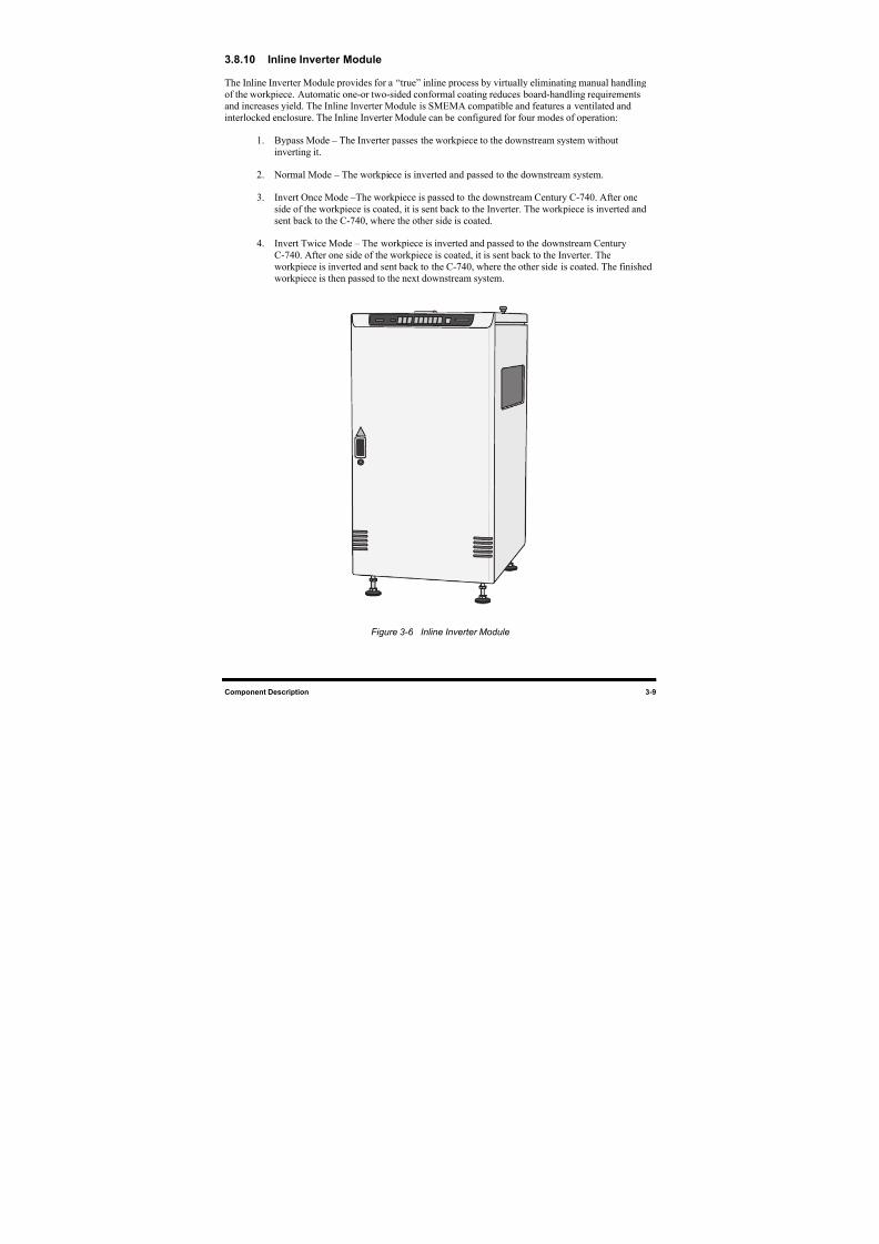
8/16/2019 Dispensig c 740 nordson
http://slidepdf.com/reader/full/dispensig-c-740-nordson 63/240
Component Description 3-9
3.8.10 Inline Inverter Module
The Inline Inverter Module provides for a “true” inline process by virtually eliminating manual handling
of the workpiece. Automatic one-or two-sided conformal coating reduces board-handling requirements
and increases yield. The Inline Inverter Module is SMEMA compatible and features a ventilated and
interlocked enclosure. The Inline Inverter Module can be configured for four modes of operation:
1. Bypass Mode – The Inverter passes the workpiece to the downstream system withoutinverting it.
2. Normal Mode – The workpiece is inverted and passed to the downstream system.
3. Invert Once Mode –The workpiece is passed to the downstream Century C-740. After one
side of the workpiece is coated, it is sent back to the Inverter. The workpiece is inverted and
sent back to the C-740, where the other side is coated.
4. Invert Twice Mode – The workpiece is inverted and passed to the downstream Century
C-740. After one side of the workpiece is coated, it is sent back to the Inverter. The
workpiece is inverted and sent back to the C-740, where the other side is coated. The finished
workpiece is then passed to the next downstream system.
Figure 3-6 Inline Inverter Module
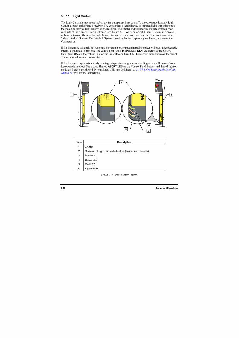
8/16/2019 Dispensig c 740 nordson
http://slidepdf.com/reader/full/dispensig-c-740-nordson 64/240
3-10 Component Description
3.8.11 Light Curtain
The Light Curtain is an optional substitute for transparent front doors. To detect obstructions, the Light
Curtain uses an emitter and a receiver. The emitter has a vertical array of infrared lights that shine upon
the matching array of light sensors on the receiver. The emitter and receiver are mounted vertically on
each side of the dispensing area entrance (see Figure 3-7). When an object 19 mm (0.75 in) in diameter
or larger interrupts the invisible light beam between an emitter/receiver pair, the blockage triggers the
Safety Interlock System. The Interlock System then disables the dispensing machinery, but leaves theComputer on.
If the dispensing system is not running a dispensing program, an intruding object will cause a recoverable
interlock condition. In this case, the yellow light in the DISPENSER STATUS section of the Control
Panel turns ON and the yellow light on the Light Beacon turns ON. To recover, simply remove the object.
The system will resume normal status.
If the dispensing system is actively running a dispensing program, an intruding object will cause a Non-
Recoverable Interlock Shutdown. The red ABORT LED on the Control Panel flashes, and the red light on
the Light Beacon and the red System Status LED turn ON. Refer to 2.10.3.1 Non-Recoverable Interlock
Shutdown for recovery instructions.
Item Description
1 Emitter
2 Close-up of Light Curtain Indicators (emitter and receiver)
3 Receiver
4 Green LED
5 Red LED
6 Yellow LED
Figure 3-7 Light Curtain (option)
2
31
4
56
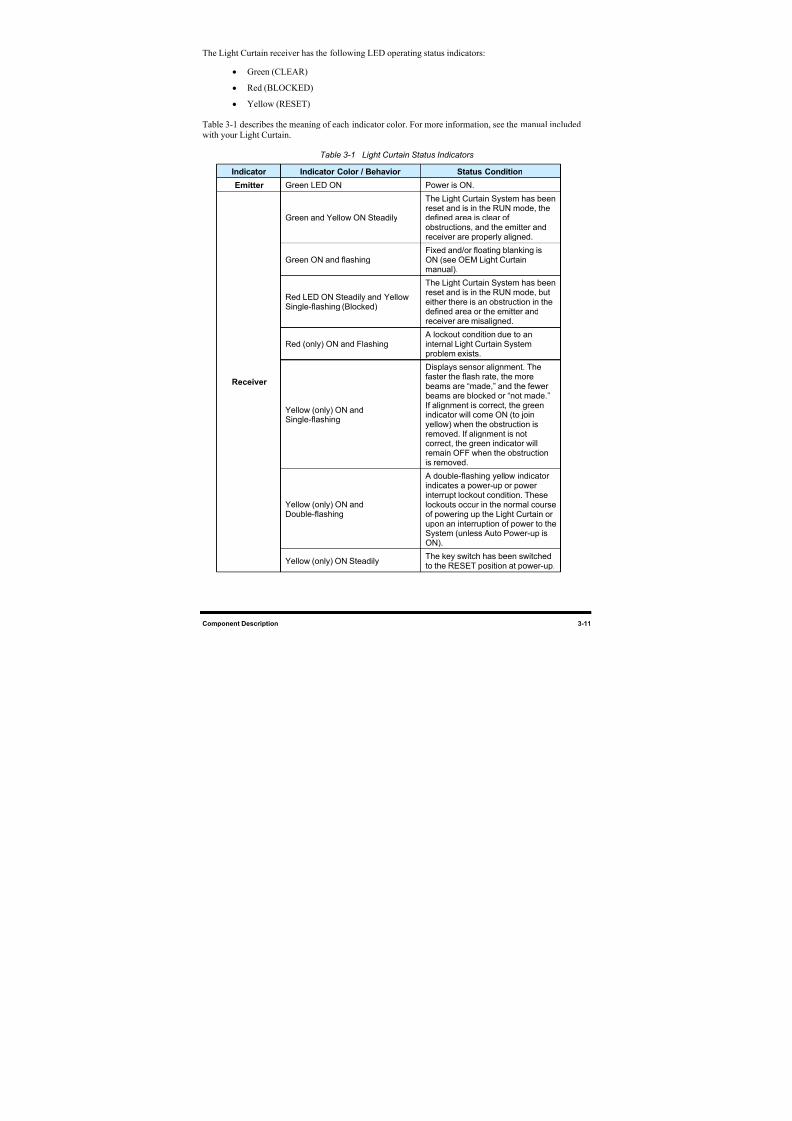
8/16/2019 Dispensig c 740 nordson
http://slidepdf.com/reader/full/dispensig-c-740-nordson 65/240
Component Description 3-11
The Light Curtain receiver has the following LED operating status indicators:
• Green (CLEAR)
• Red (BLOCKED)
• Yellow (RESET)
Table 3-1 describes the meaning of each indicator color. For more information, see the manual includedwith your Light Curtain.
Table 3-1 Light Curtain Status Indicators
Indicator Indicator Color / Behavior Status Condition
Emitter Green LED ON Power is ON.
Green and Yellow ON Steadily
The Light Curtain System has beenreset and is in the RUN mode, thedefined area is clear ofobstructions, and the emitter andreceiver are properly aligned.
Green ON and flashing Fixed and/or floating blanking isON (see OEM Light Curtainmanual).
Red LED ON Steadily and YellowSingle-flashing (Blocked)
The Light Curtain System has beenreset and is in the RUN mode, buteither there is an obstruction in thedefined area or the emitter andreceiver are misaligned.
Red (only) ON and Flashing A lockout condition due to aninternal Light Curtain Systemproblem exists.
Yellow (only) ON andSingle-flashing
Displays sensor alignment. The
faster the flash rate, the morebeams are “made,” and the fewerbeams are blocked or “not made.”If alignment is correct, the greenindicator will come ON (to joinyellow) when the obstruction isremoved. If alignment is notcorrect, the green indicator willremain OFF when the obstructionis removed.
Yellow (only) ON andDouble-flashing
A double-flashing yellow indicatorindicates a power-up or powerinterrupt lockout condition. These
lockouts occur in the normal courseof powering up the Light Curtain orupon an interruption of power to theSystem (unless Auto Power-up isON).
Receiver
Yellow (only) ON SteadilyThe key switch has been switchedto the RESET position at power-up.
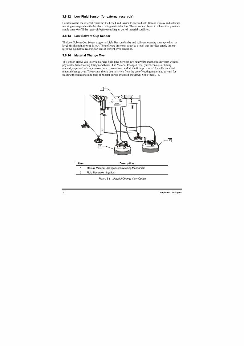
8/16/2019 Dispensig c 740 nordson
http://slidepdf.com/reader/full/dispensig-c-740-nordson 66/240
3-12 Component Description
3.8.12 Low Fluid Sensor (for external reservoir)
Located within the external reservoir, the Low Fluid Sensor triggers a Light Beacon display and software
warning message when the level of coating material is low. The sensor can be set to a level that provides
ample time to refill the reservoir before reaching an out-of-material condition.
3.8.13 Low Solvent Cup Sensor
The Low Solvent Cup Sensor triggers a Light Beacon display and software warning message when the
level of solvent in the cup is low. The software timer can be set to a level that provides ample time to
refill the cup before reaching an out-of-solvent error condition.
3.8.14 Material Change Over
This option allows you to switch air and fluid lines between two reservoirs and the fluid system without
physically disconnecting fittings and hoses. The Material Change Over System consists of tubing,
manually operated valves, controls, an extra reservoir, and all the fittings required for self-contained
material change over. The system allows you to switch from the use of coating material to solvent for
flushing the fluid lines and fluid applicator during extended shutdown. See Figure 3-8.
Item Description
1 Manual Material Changeover Switching Mechanism
2 Fluid Reservoir (1 gallon)
Figure 3-8 Material Change Over Option
1
2
2
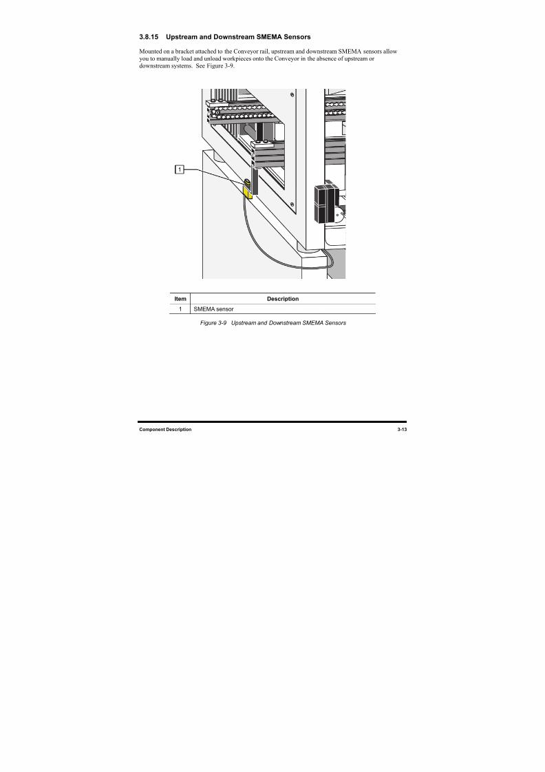
8/16/2019 Dispensig c 740 nordson
http://slidepdf.com/reader/full/dispensig-c-740-nordson 67/240
Component Description 3-13
3.8.15 Upstream and Downstream SMEMA Sensors
Mounted on a bracket attached to the Conveyor rail, upstream and downstream SMEMA sensors allow
you to manually load and unload workpieces onto the Conveyor in the absence of upstream or
downstream systems. See Figure 3-9.
Item Description
1 SMEMA sensor
Figure 3-9 Upstream and Downstream SMEMA Sensors
1
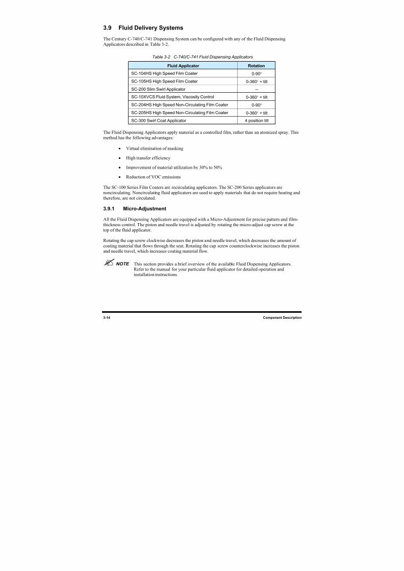
8/16/2019 Dispensig c 740 nordson
http://slidepdf.com/reader/full/dispensig-c-740-nordson 68/240
3-14 Component Description
3.9 Fluid Delivery Systems
The Century C-740/C-741 Dispensing System can be configured with any of the Fluid Dispensing
Applicators described in Table 3-2.
Table 3-2 C-740/C-741 Fluid Dispensing Applicators
Fluid Applicator Rotation
SC-104HS High Speed Film Coater 0-90°
SC-105HS High Speed Film Coater 0-360° + tilt
SC-200 Slim Swirl Applicator --
SC-10XVCS Fluid System, Viscosity Control 0-360° + tilt
SC-204HS High Speed Non-Circulating Film Coater 0-90°
SC-205HS High Speed Non-Circulating Film Coater 0-360° + tilt
SC-300 Swirl Coat Applicator 4 position tilt
The Fluid Dispensing Applicators apply material as a controlled film, rather than an atomized spray. This
method has the following advantages:
• Virtual elimination of masking
• High transfer efficiency
• Improvement of material utilization by 30% to 50%
• Reduction of VOC emissions
The SC-100 Series Film Coaters are recirculating applicators. The SC-200 Series applicators are
noncirculating. Noncirculating fluid applicators are used to apply materials that do not require heating andtherefore, are not circulated.
3.9.1 Micro-Adjustment
All the Fluid Dispensing Applicators are equipped with a Micro-Adjustment for precise pattern and film-
thickness control. The piston and needle travel is adjusted by rotating the micro-adjust cap screw at the
top of the fluid applicator.
Rotating the cap screw clockwise decreases the piston and needle travel, which decreases the amount of
coating material that flows through the seat. Rotating the cap screw counterclockwise increases the pistonand needle travel, which increases coating material flow.
NOTE This section provides a brief overview of the available Fluid Dispensing Applicators.Refer to the manual for your particular fluid applicator for detailed operation andinstallation instructions.
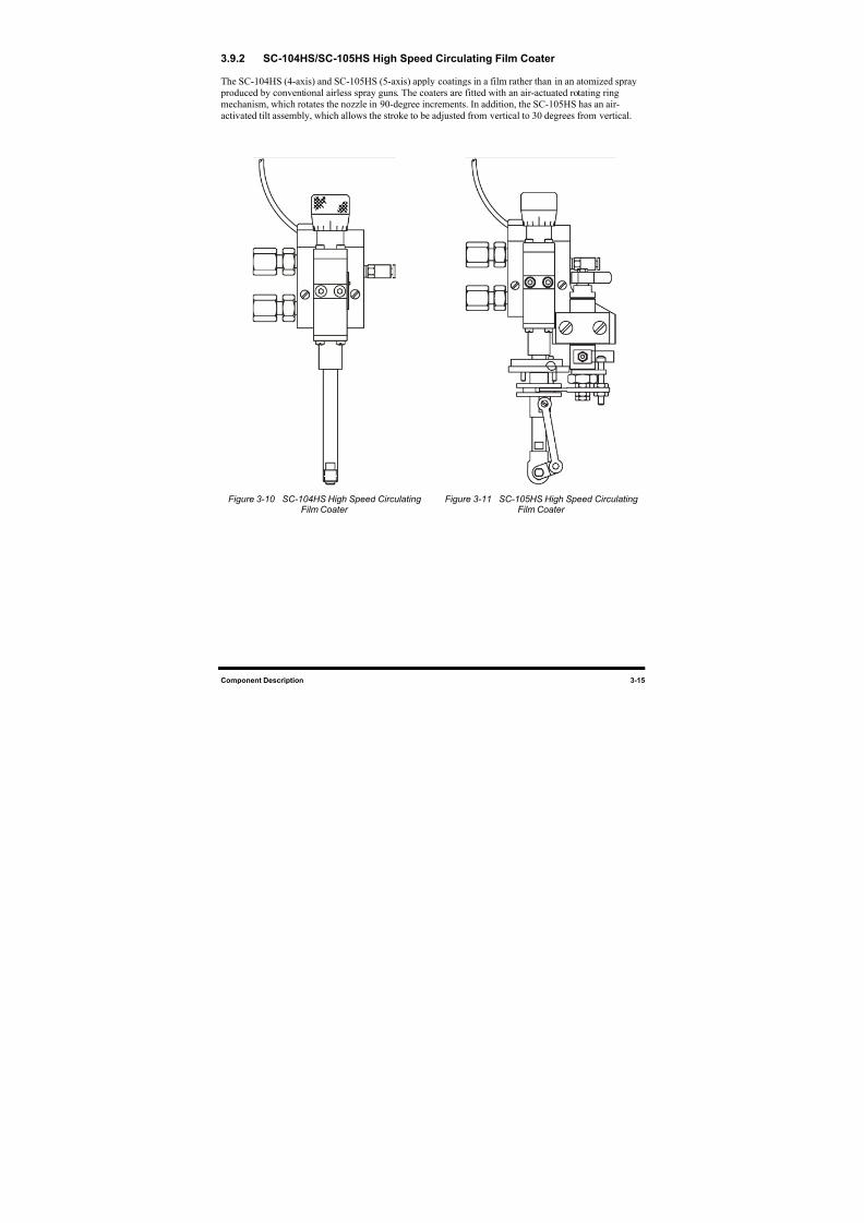
8/16/2019 Dispensig c 740 nordson
http://slidepdf.com/reader/full/dispensig-c-740-nordson 69/240
Component Description 3-15
3.9.2 SC-104HS/SC-105HS High Speed Circulating Film Coater
The SC-104HS (4-axis) and SC-105HS (5-axis) apply coatings in a film rather than in an atomized spray
produced by conventional airless spray guns. The coaters are fitted with an air-actuated rotating ring
mechanism, which rotates the nozzle in 90-degree increments. In addition, the SC-105HS has an air-
activated tilt assembly, which allows the stroke to be adjusted from vertical to 30 degrees from vertical.
Figure 3-10 SC-104HS High Speed CirculatingFilm Coater
Figure 3-11 SC-105HS High Speed CirculatingFilm Coater
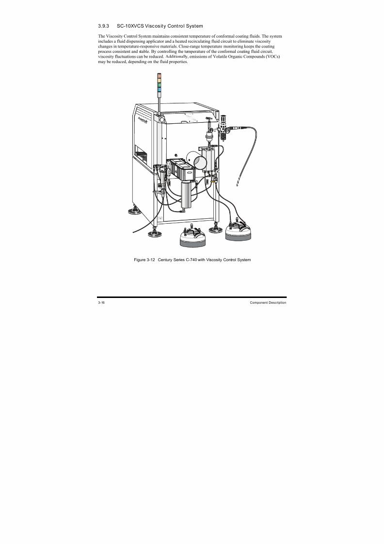
8/16/2019 Dispensig c 740 nordson
http://slidepdf.com/reader/full/dispensig-c-740-nordson 70/240
3-16 Component Description
3.9.3 SC-10XVCS Viscosity Control System
The Viscosity Control System maintains consistent temperature of conformal coating fluids. The system
includes a fluid dispensing applicator and a heated recirculating fluid circuit to eliminate viscosity
changes in temperature-responsive materials. Close-range temperature monitoring keeps the coating
process consistent and stable. By controlling the temperature of the conformal coating fluid circuit,
viscosity fluctuations can be reduced. Additionally, emissions of Volatile Organic Compounds (VOCs)
may be reduced, depending on the fluid properties.
Figure 3-12 Century Series C-740 with Viscosity Control System
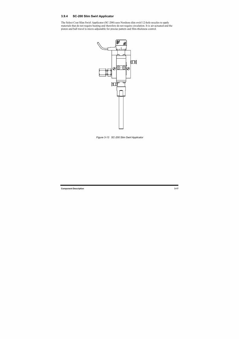
8/16/2019 Dispensig c 740 nordson
http://slidepdf.com/reader/full/dispensig-c-740-nordson 71/240
Component Description 3-17
3.9.4 SC-200 Slim Swirl Applicator
The Select Coat Slim Swirl Applicator (SC-200) uses Nordson slim swirl 12-hole nozzles to apply
materials that do not require heating and therefore do not require circulation. It is air-actuated and the
piston and ball travel is micro-adjustable for precise pattern and film-thickness control.
Figure 3-13 SC-200 Slim Swirl Applicator
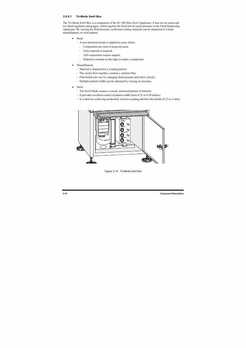
8/16/2019 Dispensig c 740 nordson
http://slidepdf.com/reader/full/dispensig-c-740-nordson 72/240
3-18 Component Description
3.9.4.1 Tri-Mode Swirl Box
The Tri-Mode Swirl Box is a component of the SC-200 Slim Swirl Applicator. It has two air assist and
two fluid regulators and gauges, which regulate the fluid and air-assist pressure to the Fluid Dispensing
Applicator. By varying the fluid pressure, conformal coating materials can be dispensed in a bead,
monofilament, or swirl pattern.
• Bead
- A non-atomized stream is applied to areas where:
Components are close to keep-out areas.
Extra material is required.
Tall components require support.
Material is needed on the edge or under a component.
• Monofilament
- Material is dispensed in a looping pattern.
- The circles flow together, creating a uniform film.
- Film builds can vary by changing fluid pressure and robot velocity.
- Multiple pattern widths can be obtained by varying air pressure.
• Swirl
- The Swirl Mode creates a conical, atomized pattern of material.
- It provides excellent control of pattern width (from 0.25 to 0.50 inches).
- It is ideal for achieving moderately selective coating and thin film builds (0.25 to 3 mils).
Figure 3-14 Tri-Mode Swirl Box
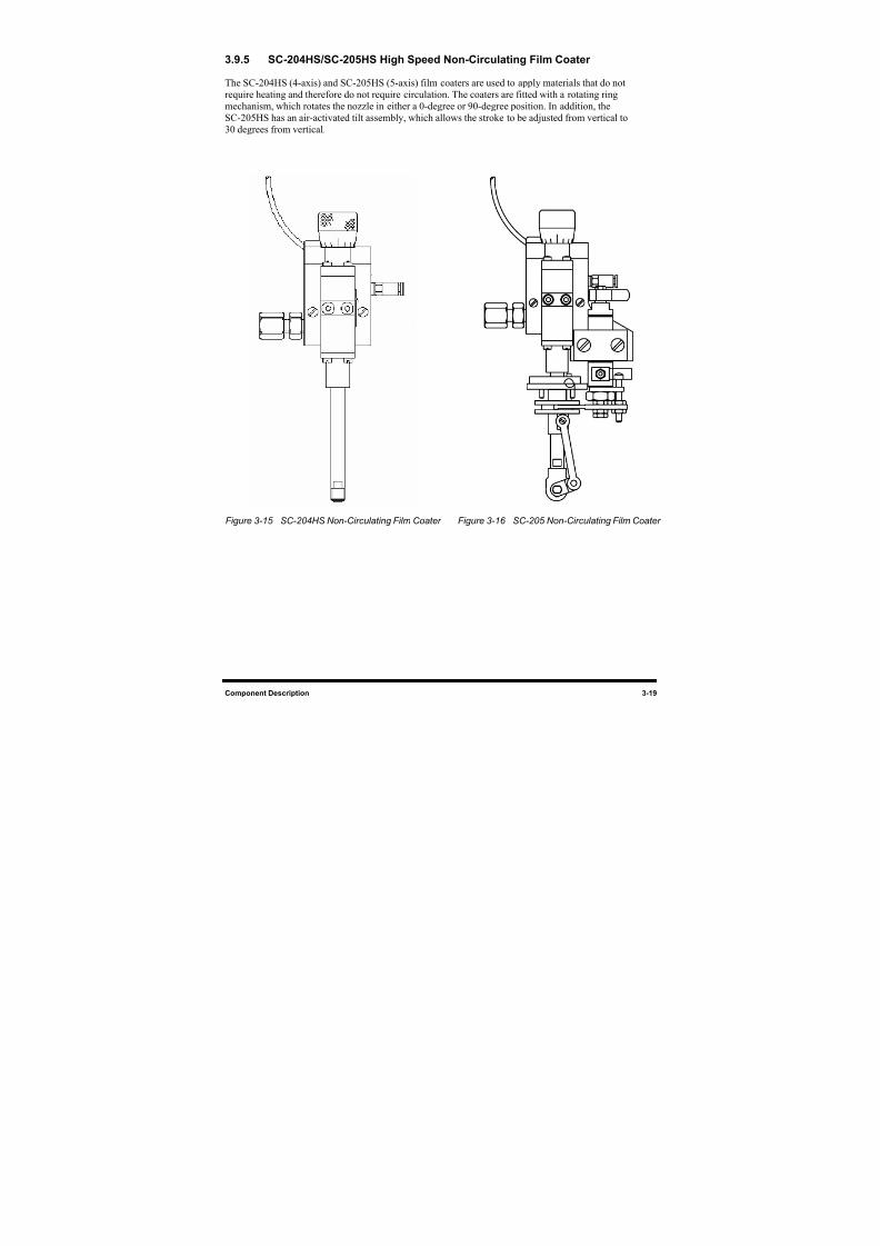
8/16/2019 Dispensig c 740 nordson
http://slidepdf.com/reader/full/dispensig-c-740-nordson 73/240
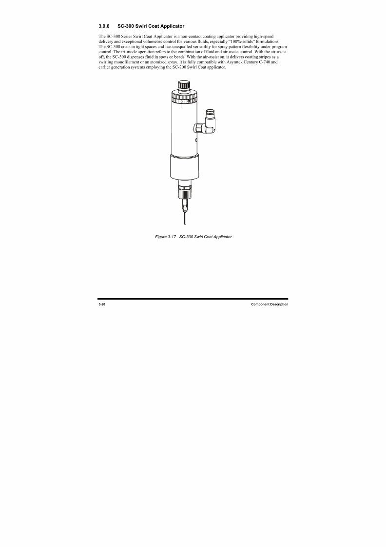
8/16/2019 Dispensig c 740 nordson
http://slidepdf.com/reader/full/dispensig-c-740-nordson 74/240
3-20 Component Description
3.9.6 SC-300 Swirl Coat Applicator
The SC-300 Series Swirl Coat Applicator is a non-contact coating applicator providing high-speed
delivery and exceptional volumetric control for various fluids, especially “100%-solids” formulations.
The SC-300 coats in tight spaces and has unequalled versatility for spray pattern flexibility under program
control. The tri-mode operation refers to the combination of fluid and air-assist control. With the air-assist
off, the SC-300 dispenses fluid in spots or beads. With the air-assist on, it delivers coating stripes as a
swirling monofilament or an atomized spray. It is fully compatible with Asymtek Century C-740 andearlier generation systems employing the SC-200 Swirl Coat applicator.
0
Figure 3-17 SC-300 Swirl Coat Applicator
8/16/2019 Dispensig c 740 nordson
http://slidepdf.com/reader/full/dispensig-c-740-nordson 75/240
Installation 4-1
4 Installation
4.1 Overview
This section describes installation procedures for the Century Series C-740/C-741 Dispensing System and
covers the following topics:
• Facility Requirements • Electrical Connections
• Uncrating and Placing the Dispensing System • Exhaust Connection
• Unpacking the Dispensing Area • Connecting Power and Air Supply
• Unpacking the Accessories Crate • Earthquake Precautions
• Leveling the Dispensing System • ECXP Configuration
• Component Installation • System Configuration
• Pneumatic Connections • Beacon Configuration
4.2 Safety First
Before performing any of the system installation procedures in this section, please review the information
presented in Section 2 - Safety.
4.3 Facility Requirements
To ensure optimal performance and safety, it is necessary to install the dispensing system in a facility that
meets or exceeds the requirements listed in Section 11 - Specifications. If you have any questions about
facility requirements, please contact Asymtek Technical Support.
WARNING! CAUTION!Make sure that your facility meets all requirements listed in Section 11 - Specifications. Failure to meet these requirements could result in seriousbodily injury to personnel and damage to the dispensing system.
8/16/2019 Dispensig c 740 nordson
http://slidepdf.com/reader/full/dispensig-c-740-nordson 76/240
4-2 Installation
4.4 Uncrating and Placing the Dispensing System
CAUTION! Check the Tip & Tell and ShockWatch devices, both on the outside of the crateand on the dispensing system, to make sure that the dispensing system has notbeen dropped or tipped over. If either of these devices has been activated,contact Asymtek Technical Support.
If the dispensing system is being installed in a clean room, uncrate the system,unpack the accessories crate and remove all packaging material includingwrapping paper and tape from all parts and components before moving anythinginto the clean room.
This installation procedure should only be performed by a trained servicetechnician.
Tools and Materials Needed:
•
Adjustable Wrench•
Hammer• 7/16-inch Wrench • Flat Bar
• 9/16-inch Wrench • Forklift
• Appropriate Personal Protective Equipment
To uncrate and place the dispensing system:
1. Check the “Tip & Tell” and “ShockWatch” devices, both on the outside of the shipping crate
and on the dispensing system, to make sure that the dispensing system has not been dropped
or tipped. If any of these devices has been activated, contact Asymtek Technical Support.
2. Locate and remove the envelope on the outside of the shipping crate. Open the envelope
and locate the shipping list and uncrating instructions inside. Place the shipping list in asafe location.
3. Referring to the uncrating instruction sheet, use the flat bar and hammer to remove the lid and
sides of the crate.
WARNING! CAUTION! Personnel should wear gloves and safety glasses while removing the top and
sides of the crate. Sufficient personnel should be used to lift and control the cratetop and sides to prevent serious injury to personnel or damage to the dispensingsystem. Refer to Section 2 - Safety .
4. Remove all packaging material from the perimeter of the dispensing system.
8/16/2019 Dispensig c 740 nordson
http://slidepdf.com/reader/full/dispensig-c-740-nordson 77/240
Installation 4-3
5. Use the 9/16-inch wrench to remove the four (4) bolts that anchor the dispensing system to
the floor of the crate.
There are two anchor brackets on the left side of the dispensing system, and two on the
right side.
6. Use the 7/16-inch wrench to remove the eight (8) bolts that hold the four anchor brackets
onto the sides of the dispensing system.
7. Use a forklift to gently lift the dispensing system off of the pallet.
NOTE Lift the dispensing system from the bottom, between the feet.
8. Place the dispensing system over the installation site, but do NOT lower the forklift at
this time.
9. Adjust the forklift height until the dispensing system is approximately at the required height.
NOTE The dispensing system Levelers should not be touching the ground. If any of the Levelers
are touching the ground, use the adjustable wrench to raise them by turning the adjustingnut counter-clockwise.
10. With the dispensing system at the approximate height and none of the feet touching the
ground, use the 9/16-inch wrench to loosen each pair of leg bolts located on each side of the
dispensing system.
NOTE Each leg should drop down after the bolts have been loosened. You should not have morethan 2 to 3 inches of leg showing.
11. When all four feet are firmly and flatly on the floor, use the 9/16-inch wrench to tighten all
four pairs of leg bolts.
12. Gently lower the forklift.
CAUTION! Use extreme caution when lowering the forklift blades. Stop lowering the blades ifthe dispensing system begins to tilt. Raise the dispensing system back to therequired height and tighten the leg bolts.
8/16/2019 Dispensig c 740 nordson
http://slidepdf.com/reader/full/dispensig-c-740-nordson 78/240
4-4 Installation
4.5 Unpacking the Dispensing Area
CAUTION! If the dispensing system is being installed in a clean room, remove all packagingmaterial and follow facility-recommended procedures before moving componentsinto the clean room.
To unpack the dispensing area:
1. Remove all perimeter packaging material from the dispensing area.
2. Remove all tie wraps, tape, foam packaging material, and warning tags from the Dispensing
Head and Conveyor (C-740) or Tooling Plate (C-741).
NOTE Location of packaging materials to be removed is indicated by the presence of redwarning tags. The amount, type, and arrangement of packaging materials will depend on
your system’s configuration.
4.6 Unpacking the Accessories Crate
NOTE The contents of the accessories crate will vary depending upon the options ordered withyour dispensing system.
Tools and Materials Needed:
• Flat Bar
• Pen or Pencil
• Appropriate Personal Protective Equipment
To unpack the accessories crate:
1. Use the flat bar and hammer to remove the crate lid.
2. Open the bag inside of the crate.
As you unpack each item inside of the box, identify the item, locate it on the shipping list,
and place a check mark next to the item.
You may need to open the item in order to identify it. Once it has been identified, return
the item to its original box or bag.
3. If any parts or accessories are missing, please contact Asymtek Technical Support.
4. Place each item from the accessories crate onto a cart for easy transport. If possible, place the
items next to the dispensing system onto which the items will be installed.
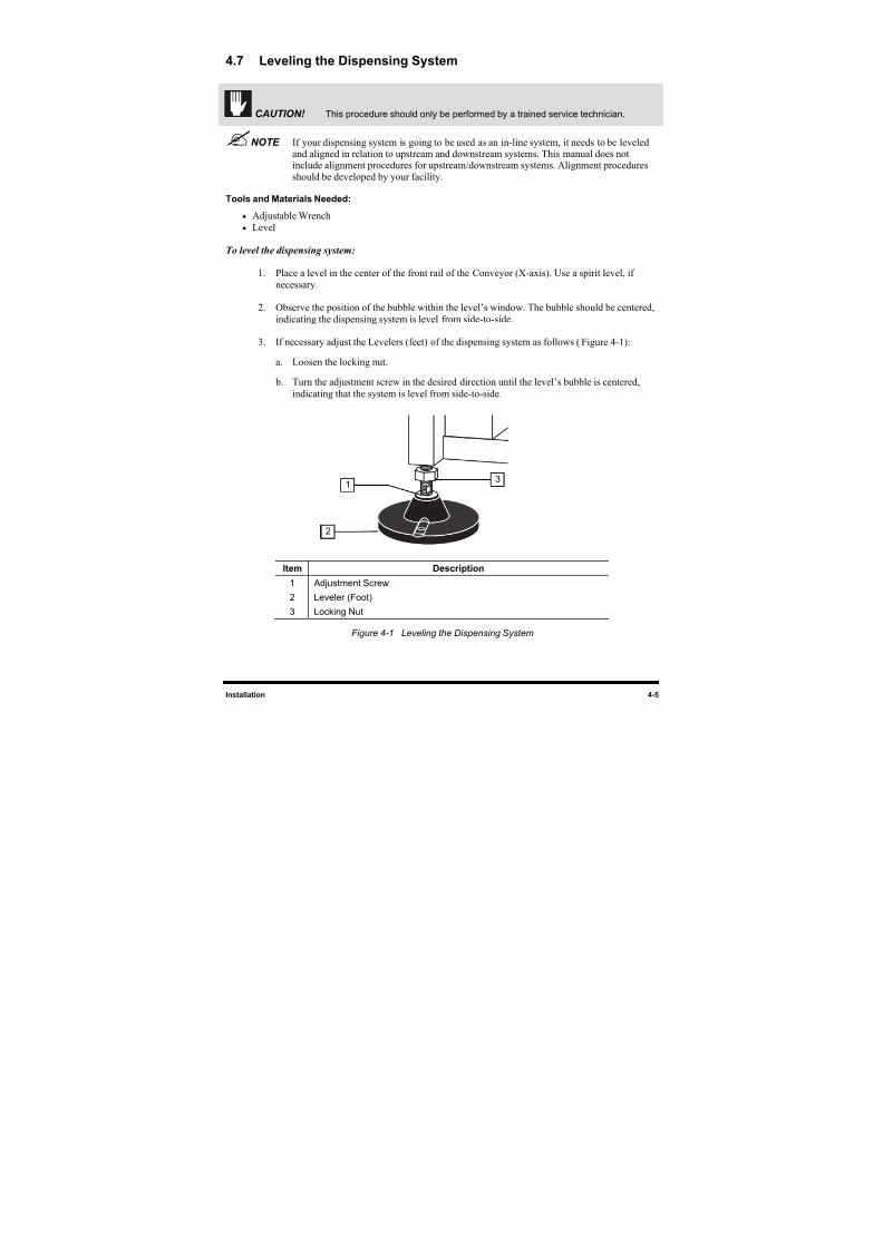
8/16/2019 Dispensig c 740 nordson
http://slidepdf.com/reader/full/dispensig-c-740-nordson 79/240
Installation 4-5
4.7 Leveling the Dispensing System
CAUTION! This procedure should only be performed by a trained service technician.
NOTE If your dispensing system is going to be used as an in-line system, it needs to be leveled
and aligned in relation to upstream and downstream systems. This manual does notinclude alignment procedures for upstream/downstream systems. Alignment proceduresshould be developed by your facility.
Tools and Materials Needed:
• Adjustable Wrench
• Level
To level the dispensing system:
1. Place a level in the center of the front rail of the Conveyor (X-axis). Use a spirit level, if
necessary.
2. Observe the position of the bubble within the level’s window. The bubble should be centered,
indicating the dispensing system is level from side-to-side.
3. If necessary adjust the Levelers (feet) of the dispensing system as follows (Figure 4-1):
a. Loosen the locking nut.
b. Turn the adjustment screw in the desired direction until the level’s bubble is centered,
indicating that the system is level from side-to-side.
Item Description
1 Adjustment Screw
2 Leveler (Foot)
3 Locking Nut
Figure 4-1 Leveling the Dispensing System
1
2
3
8/16/2019 Dispensig c 740 nordson
http://slidepdf.com/reader/full/dispensig-c-740-nordson 80/240
4-6 Installation
4. Place a level in the center of the left Y-rail of the Conveyor.
5. Observe the position of the bubble within the level’s window. The bubble should be centered,
indicating the dispensing system is level from side-to-side.
6. If necessary adjust the Levelers (feet) of the dispensing system as described in Steps 3a
and 3b.
7. Place a level in the center of the right Y-rail of the Conveyor.
8. Observe the position of the bubble within the level’s window. The bubble should be centered,
indicating the dispensing system is level from side-to-side.
9. If necessary adjust the Levelers (feet) of the dispensing system as described in Steps 3a
and 3b.
10. When the dispensing system is level, lock the footpad adjustment firmly in place by
tightening the locking nut.
11. Align the dispensing system so that the Conveyor is parallel to the mating conveyer, if theunit is integrated in a production line.
4.8 Component Installation
Your Century C-740/C-741 dispensing system is assembled at the Asymtek factory. However, to protect
components during shipment, some are packaged in the accessories crate to be installed after arrival.
Once installed, these components are functionally tested along with the rest of the system as detailed in
Section 5 - Power-up and Testing.
4.8.1 Installing the Fluid Dispensing Applicator
The Fluid Dispensing Applicator should have already been installed on your dispensing system at theAsymtek factory. If it has not been installed, a trained service technician should install it in accordance
with the appropriate fluid applicator manual.
4.8.2 Installing the Monitor
CAUTION! Make sure all power sources are disconnected before performing this procedure.This procedure should only be performed by a trained service technician.
Tools and Materials Needed:
• Monitor (P/N 07-6002-00) • Monitor Computer Cable
• 1/8-inch Hex Key • Monitor Power Cable
NOTE All materials are included in the accessories crate that accompanied your dispensingsystem.
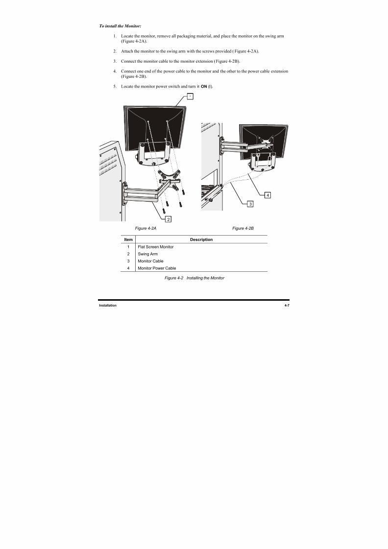
8/16/2019 Dispensig c 740 nordson
http://slidepdf.com/reader/full/dispensig-c-740-nordson 81/240
Installation 4-7
To install the Monitor:
1. Locate the monitor, remove all packaging material, and place the monitor on the swing arm
(Figure 4-2A).
2. Attach the monitor to the swing arm with the screws provided (Figure 4-2A).
3. Connect the monitor cable to the monitor extension (Figure 4-2B).
4. Connect one end of the power cable to the monitor and the other to the power cable extension
(Figure 4-2B).
5. Locate the monitor power switch and turn it ON (I).
Figure 4-2 A Figure 4-2 B
Item Description
1 Flat Screen Monitor2 Swing Arm
3 Monitor Cable
4 Monitor Power Cable
Figure 4-2 Installing the Monitor
1
2
3
4
8/16/2019 Dispensig c 740 nordson
http://slidepdf.com/reader/full/dispensig-c-740-nordson 82/240
4-8 Installation
4.8.3 Installing the Keyboard and Mouse
CAUTION! Make sure all power sources are disconnected before performing this procedure.This procedure should only be performed by a trained service technician.
Tools and Materials Needed:
• Keyboard (P/N 194748)
• Mouse (P/N 194459)
To install the Keyboard and Mouse:
1. Unpack the keyboard from its box and remove all packaging material.
2. Place the keyboard on the keyboard tray so that the left edge of the keyboard lines up with the
left edge of the plate.
3. Locate the mouse and keyboard cables in the lower cabinet and remove all
packaging material.
4. Connect the keyboard cable to the cable protruding from the port on the side of the
dispensing system (Figure 4-3).
5. Locate the mouse and remove all packaging material.
6. Place the mouse on the keyboard plate in the space to the right of the keyboard.
7. Connect the end of the mouse cable extending from the back of the dispensing system to the
mouse cable attached to the mouse.
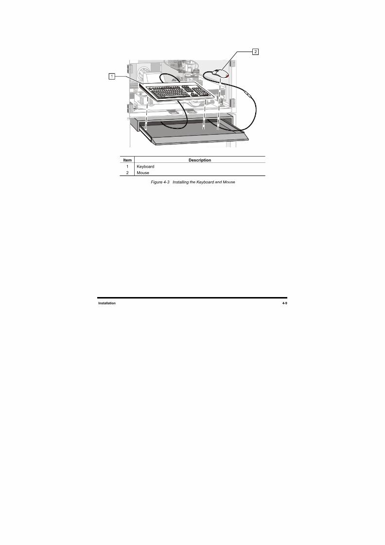
8/16/2019 Dispensig c 740 nordson
http://slidepdf.com/reader/full/dispensig-c-740-nordson 83/240
Installation 4-9
Item Description
1 Keyboard
2 Mouse
Figure 4-3 Installing the Keyboard and Mouse
2
1
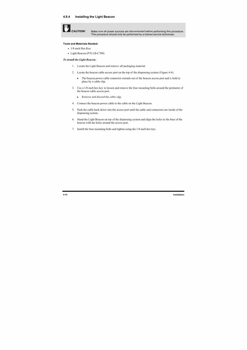
8/16/2019 Dispensig c 740 nordson
http://slidepdf.com/reader/full/dispensig-c-740-nordson 84/240
4-10 Installation
4.8.4 Installing the Light Beacon
CAUTION! Make sure all power sources are disconnected before performing this procedure.This procedure should only be performed by a trained service technician.
Tools and Materials Needed:
• 1/8-inch Hex Key
• Light Beacon (P/N LB-C700)
To install the Light Beacon:
1. Locate the Light Beacon and remove all packaging material.
2. Locate the beacon cable access port on the top of the dispensing system (Figure 4-4).
The beacon power cable connector extends out of the beacon access port and is held in place by a cable clip.
3. Use a 1/8-inch hex key to loosen and remove the four mounting bolts around the perimeter ofthe beacon cable access port.
Remove and discard the cable clip.
4. Connect the beacon power cable to the cable on the Light Beacon.
5. Push the cable back down into the access port until the cable and connectors are inside of the
dispensing system.
6. Stand the Light Beacon on top of the dispensing system and align the holes in the base of the beacon with the holes around the access port.
7. Install the four mounting bolts and tighten using the 1/8-inch hex key.
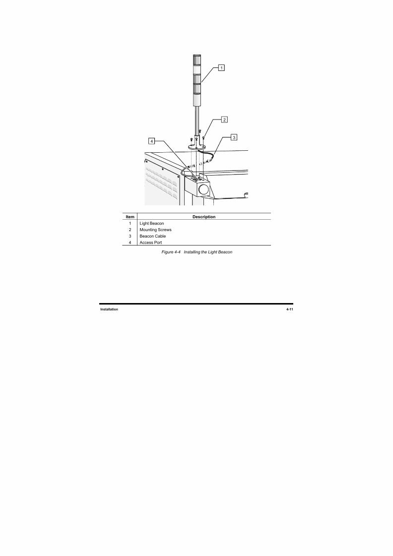
8/16/2019 Dispensig c 740 nordson
http://slidepdf.com/reader/full/dispensig-c-740-nordson 85/240
Installation 4-11
Item Description
1 Light Beacon
2 Mounting Screws
3 Beacon Cable
4 Access Port
Figure 4-4 Installing the Light Beacon
1
2
34
8/16/2019 Dispensig c 740 nordson
http://slidepdf.com/reader/full/dispensig-c-740-nordson 86/240
4-12 Installation
4.9 Pneumatic Connections
The C-740/C-741 Series Dispensing System requires 85 l/min (3 scfm) of clean, dry air delivered through
a 12.7 mm (0.5 inch) pipe or hose at 80 to 100 psi (551 to 689 kPa). Connect the air supply to the ¼ -inch
NPT quick-disconnect fitting at the Main Air Inlet (Figure 4-5).
NOTE
The maximum air supply pressure should not exceed 100 psi (689 kPa).
WARNING! CAUTION!
All system pneumatic connections should be checked before the main airis connected.
Refer to Appendix A for C-740/C-741 Series Dispensing Systems pneumatic diagrams.
4.10 Electrical Connections
The dispensing system requires 1 kw of single-phase power at 100, 120, 220, or 240 VAC.
NOTE Refer to Section 11 - Specifications for more information on electrical requirements.Contact your Asymtek representative for your particular system requirements.
Refer to Appendix B for C-740/C-741 Series Dispensing Systems electrical diagrams. Dispensing system
electronic connections are detailed in Appendix D.
4.11 Exhaust Connection
The dispensing system requires a 15.3 cm (6 inch) diameter exhaust duct capable of drawing a minimum
of 0.28 m3/s (600 scfm) air at 25.4 mm (1 inch) water column (w.c.) static pressure.
NOTE Refer to Section 11 - Specifications for more information on exhaust requirements.Contact your Asymtek representative for your particular system requirements.
8/16/2019 Dispensig c 740 nordson
http://slidepdf.com/reader/full/dispensig-c-740-nordson 87/240
Installation 4-13
4.12 Connecting Power and Air Supply
WARNING! CAUTION!Make sure that your facility meets all requirements listed in Section 11 - Specifications. Failure to meet these requirements could result in serious bodilyinjury to personnel and damage to the dispensing system.
CAUTION! This procedure should only be performed by a trained service technician.
Tools and Materials Needed:
• Main Power Cable
• Quick Release Air Hose Nozzle
To connect the facilities power and air supply:
1. Unpack the main power cable and remove all packing material including plastic wrappers and
tie wraps.
2. Plug the female end of the power cable into the main power inlet on the lower left side of
the dispensing system. Plug the male end of the power cable into the facility power source
(Figure 4-5).
CAUTION! Switch the Main Circuit Breaker to the OFF (0) position before proceeding.
3. Locate and attach the quick disconnect air nozzle to the facility air hose.
4. Connect the facility air hose to the main air inlet connector on the back right side of the
dispensing system.
5. Install a damper at the exhaust duct.
6. Connect the facility exhaust ventilation system ductwork to the exhaust vent duct
(Figure 4-5).
7. Adjust airflow to a minimum of 400 scfm with the Conveyor doors closed.
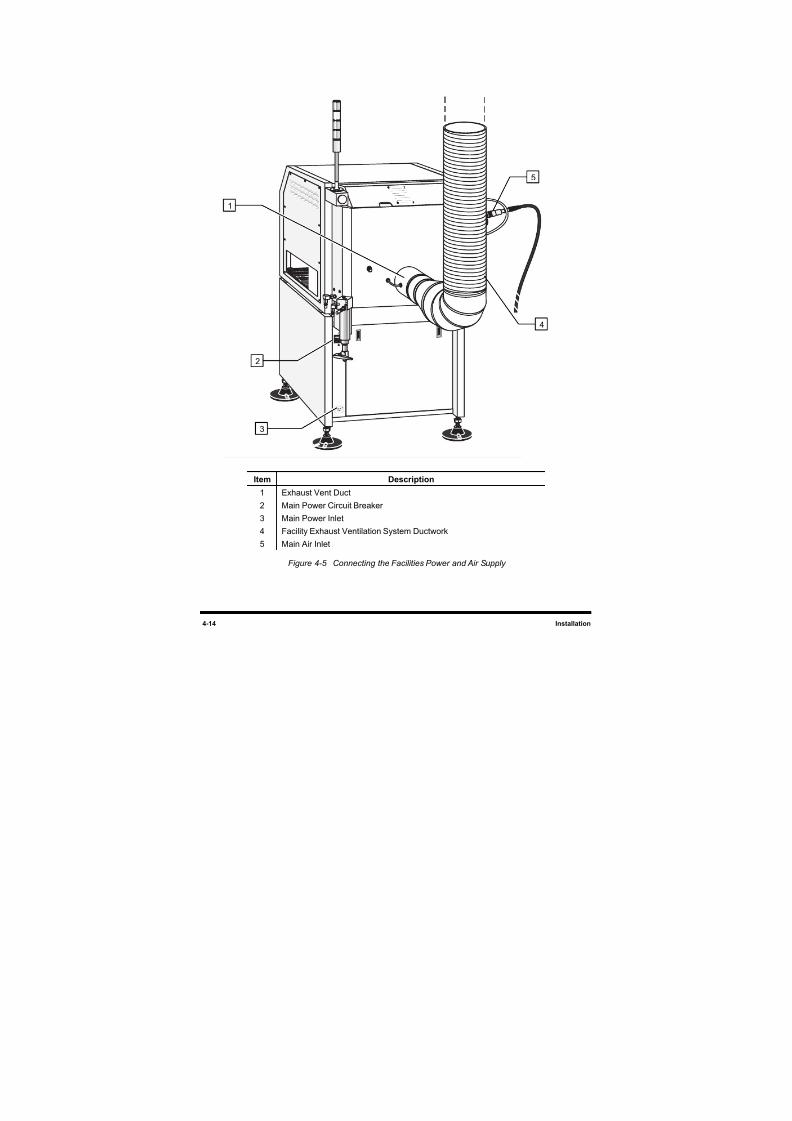
8/16/2019 Dispensig c 740 nordson
http://slidepdf.com/reader/full/dispensig-c-740-nordson 88/240
4-14 Installation
Item Description
1 Exhaust Vent Duct
2 Main Power Circuit Breaker3 Main Power Inlet
4 Facility Exhaust Ventilation System Ductwork
5 Main Air Inlet
Figure 4-5 Connecting the Facilities Power and Air Supply
5
3
2
4
1
8/16/2019 Dispensig c 740 nordson
http://slidepdf.com/reader/full/dispensig-c-740-nordson 89/240
Installation 4-15
4.13 Earthquake Precautions
To prevent the dispensing system from moving during an earthquake, the system should be anchored to
the floor. The anchor joint (the point between each screw and the floor) must be able to withstand 100 kg
(220 lbs) of pullout force. Each footpad should be anchored to the floor with two screws. Asymtek
recommends using M10 x 1.5 (or 3/8–24 UNF) screws. Refer to 2.6 Earthquake Precautions for
additional information.
4.14 ECXP Configuration
4.14.1 ECW.INI File
When ECXP is installed, the ECW.INI file is created. This file contains settings for your system
hardware. The first time ECXP is run, a setup procedure runs, asking you what hardware you have and
how it is configured. Responses to each question are written into the ECW.INI file. All other settings are
performed from the Configure menu on the Edit screen described in 4.15 System Configuration. For
more detailed information, see the Easy Coat User Guide.
NOTE In most cases, ECXP arrives already installed and configured for your dispensing system
from the Asymtek factory.
4.14.1.1 Backup
Backup of the ECW.INI file is automatic. Each time the file is edited, the previous version is saved as
ECWyearmonthdayhourminutesecond.ini. Before editing a newly installed ECW.INI file, you should
make a copy on a floppy disk or in another directory on the hard drive.
To prevent losing your configuration once you have ECXP set up, you can copy the ECW.INI
configuration file to a floppy disk or to another folder on your hard drive. You should do this every time
you make a change to your configuration. You can rename the configuration files to distinguish one from
another, but before you restore the file you must rename it as ECW.INI.
To back up your configuration, click on Help > Copy Configuration To Disk. ECXP looks for a disk in
the A drive. If one is present and has enough room on it, copying takes place automatically. If there is no
disk in the drive, an error message appears. Insert a floppy disk in the drive and click on Retry. If you
want to copy to a folder on the hard drive, click Cancel in the error message box. The Save As
dialog
appears. Use the file manager to select the folder that you want to copy to, then click on Save.
WARNING! Do not edit the ECW.INI file unless it is absolutely necessary and you have beentrained to do so. An error in this file can cause your system to run erratically, ornot at all. Contact your Asymtek representative before editing this file.
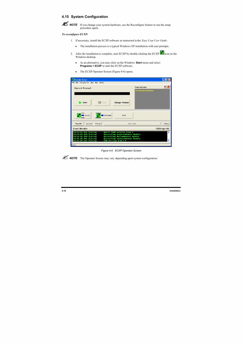
8/16/2019 Dispensig c 740 nordson
http://slidepdf.com/reader/full/dispensig-c-740-nordson 90/240
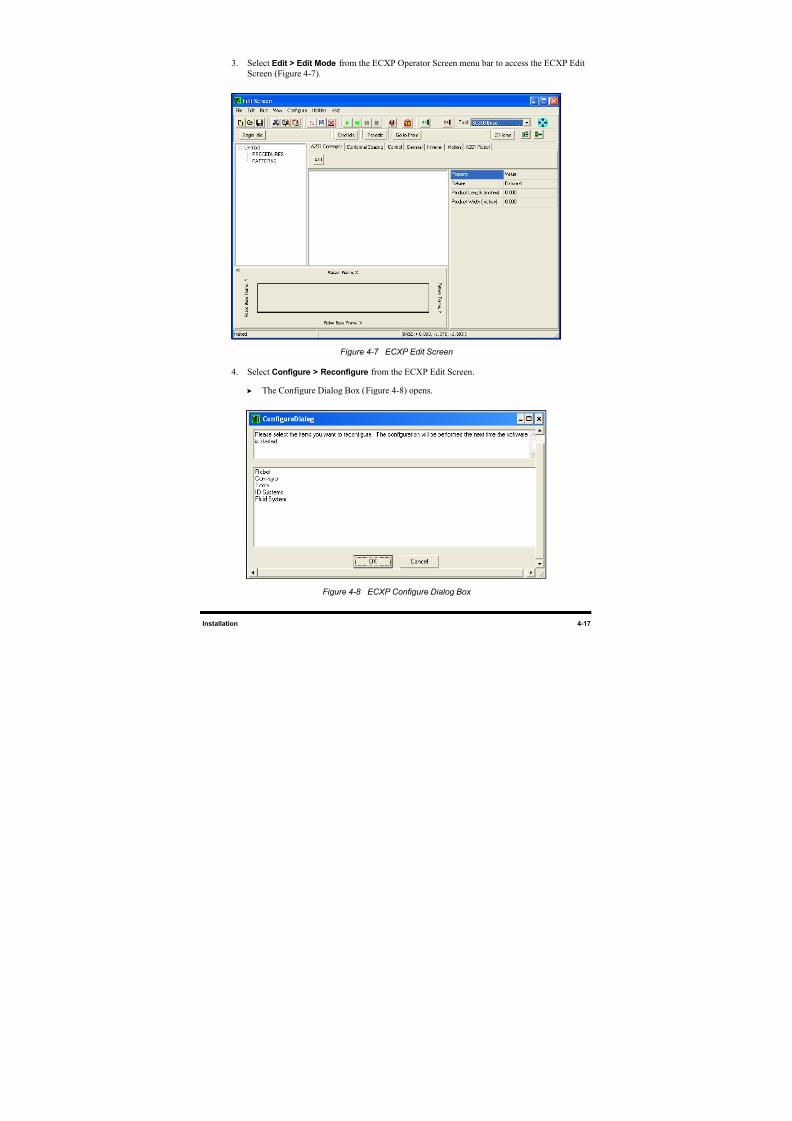
8/16/2019 Dispensig c 740 nordson
http://slidepdf.com/reader/full/dispensig-c-740-nordson 91/240
8/16/2019 Dispensig c 740 nordson
http://slidepdf.com/reader/full/dispensig-c-740-nordson 92/240
4-18 Installation
5. Select the item to be configured by clicking on it.
NOTE To select more than one item, hold down the CTRL key while selectingadditional items.
6. When you are finished, click on OK.
The software must be restarted in order to perform the configuration.
7. To close the ECXP Edit Screen and return to the Operator Screen, click on or select
File > Exit from the menu bar.
8. To exit ECXP, click on or select File > Exit from the Operator Screen menu bar.
9. Restart ECXP to perform the configuration procedure. ECXP will prompt you to answer a
series of questions defining your system configuration.
NOTE Prompts will vary depending on the items selected and answers to previous prompts.
10. Once you have responded to all the prompts, the ECXP program will start.
NOTE ECXP menu choices may vary depending on the answers to the prompts. Refer tothe Easy Coat User Guide for detailed instructions.
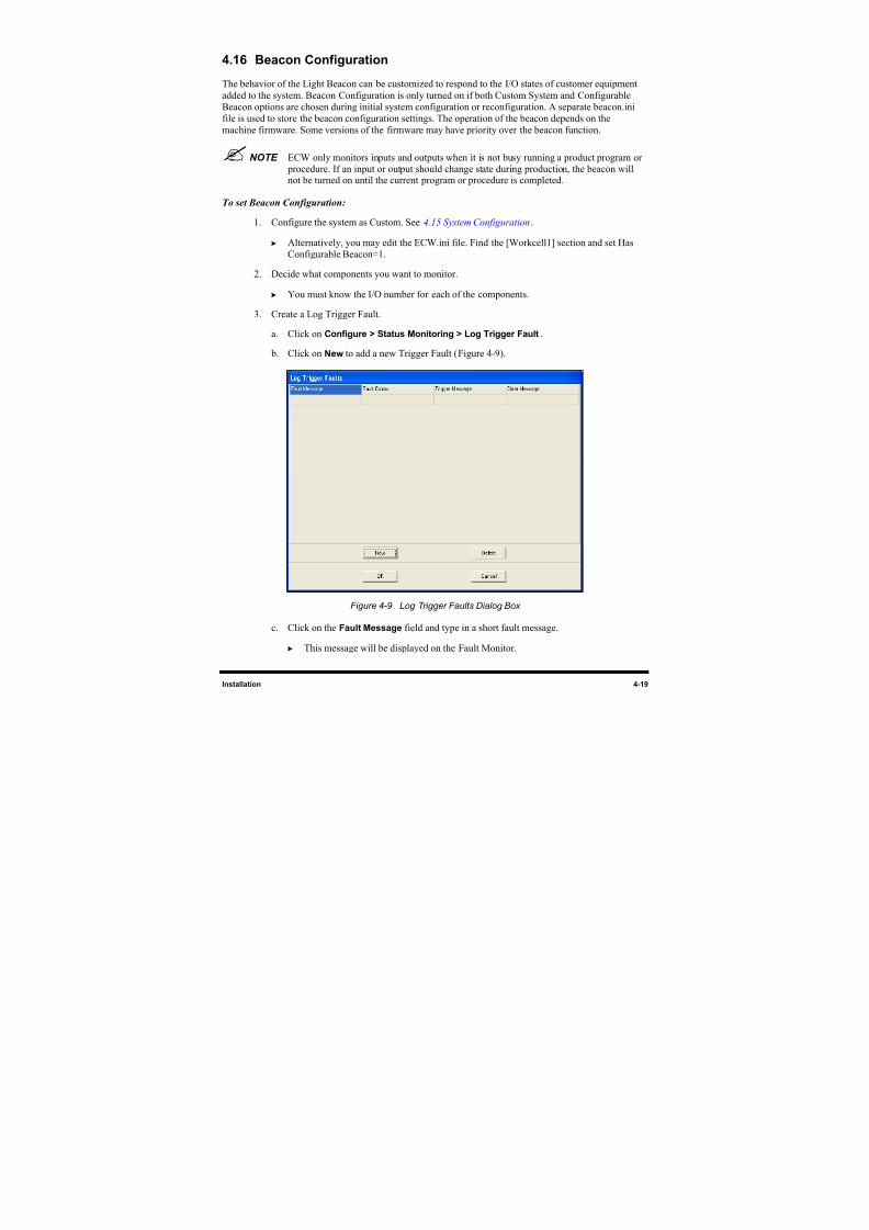
8/16/2019 Dispensig c 740 nordson
http://slidepdf.com/reader/full/dispensig-c-740-nordson 93/240
Installation 4-19
4.16 Beacon Configuration
The behavior of the Light Beacon can be customized to respond to the I/O states of customer equipment
added to the system. Beacon Configuration is only turned on if both Custom System and Configurable
Beacon options are chosen during initial system configuration or reconfiguration. A separate beacon.ini
file is used to store the beacon configuration settings. The operation of the beacon depends on the
machine firmware. Some versions of the firmware may have priority over the beacon function.
NOTE ECW only monitors inputs and outputs when it is not busy running a product program or procedure. If an input or output should change state during production, the beacon willnot be turned on until the current program or procedure is completed.
To set Beacon Configuration:
1. Configure the system as Custom. See 4.15 System Configuration.
Alternatively, you may edit the ECW.ini file. Find the [Workcell1] section and set Has
Configurable Beacon=1.
2. Decide what components you want to monitor.
You must know the I/O number for each of the components.
3. Create a Log Trigger Fault.
a. Click on Configure > Status Monitoring > Log Trigger Fault.
b. Click on New to add a new Trigger Fault (Figure 4-9).
Figure 4-9 Log Trigger Faults Dialog Box
c. Click on the Fault Message field and type in a short fault message.
This message will be displayed on the Fault Monitor.
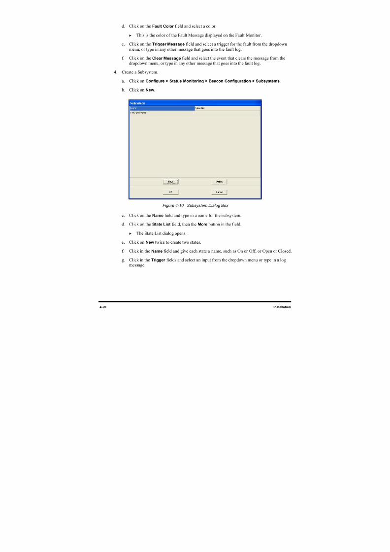
8/16/2019 Dispensig c 740 nordson
http://slidepdf.com/reader/full/dispensig-c-740-nordson 94/240
4-20 Installation
d. Click on the Fault Color field and select a color.
This is the color of the Fault Message displayed on the Fault Monitor.
e. Click on the Trigger Message field and select a trigger for the fault from the dropdown
menu, or type in any other message that goes into the fault log.
f. Click on the Clear Message field and select the event that clears the message from the
dropdown menu, or type in any other message that goes into the fault log.
4. Create a Subsystem.
a. Click on Configure > Status Monitoring > Beacon Configuration > Subsystems.
b. Click on New.
Figure 4-10 Subsystem Dialog Box
c. Click on the Name field and type in a name for the subsystem.
d. Click on the State List field, then the More button in the field.
The State List dialog opens.
e. Click on New twice to create two states.
f. Click in the Name field and give each state a name, such as On or Off, or Open or Closed.
g. Click in the Trigger fields and select an input from the dropdown menu or type in a log
message.
8/16/2019 Dispensig c 740 nordson
http://slidepdf.com/reader/full/dispensig-c-740-nordson 95/240
Power-up and Testing 5-1
5 Power-up and Testing
5.1 Overview
Once you have performed all of the procedures described in Section 4 - Installation, you are ready to
power-up the dispensing system. This section describes the power-up and testing procedures for making
sure that all system components are functioning and communicating properly. This section covers thefollowing topics:
• Powering Up the System • Robot (Dispensing Head) Function
• Starting Easy Coat for Windows (ECXP) • Conveyor Panel/Mechanics (C-740)
• Robot/Conveyor I/O • Dispensing System Options
• Pneumatics
5.2 Safety First
Before operating the dispensing system, please review the information presented in Section 2 - Safety.
5.3 Powering Up the System
To power on the dispensing system:
1. Verify that the main power cord is connected to the Main Power Inlet and the facility
power source.
2. Verify that the facility air hose is connected to the Main Air Inlet (Figure 5-1).
3. Verify that the Facility Exhaust Ventilation System ductwork is connected to the Exhaust
Vent Duct (Figure 5-1).
NOTE Refer to “Connecting Power and Air Supply” in Section 4 - Installation forconnection instructions for Steps 1-3 above.
4. Turn the Main Circuit Breaker to the ON (I) position.
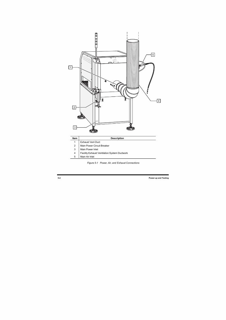
8/16/2019 Dispensig c 740 nordson
http://slidepdf.com/reader/full/dispensig-c-740-nordson 96/240
5-2 Power-up and Testing
Item Description
1 Exhaust Vent Duct
2 Main Power Circuit Breaker
3 Main Power Inlet
4 Facility Exhaust Ventilation System Ductwork
5 Main Air Inlet
Figure 5-1 Power, Air, and Exhaust Connections
5
3
4
2
1
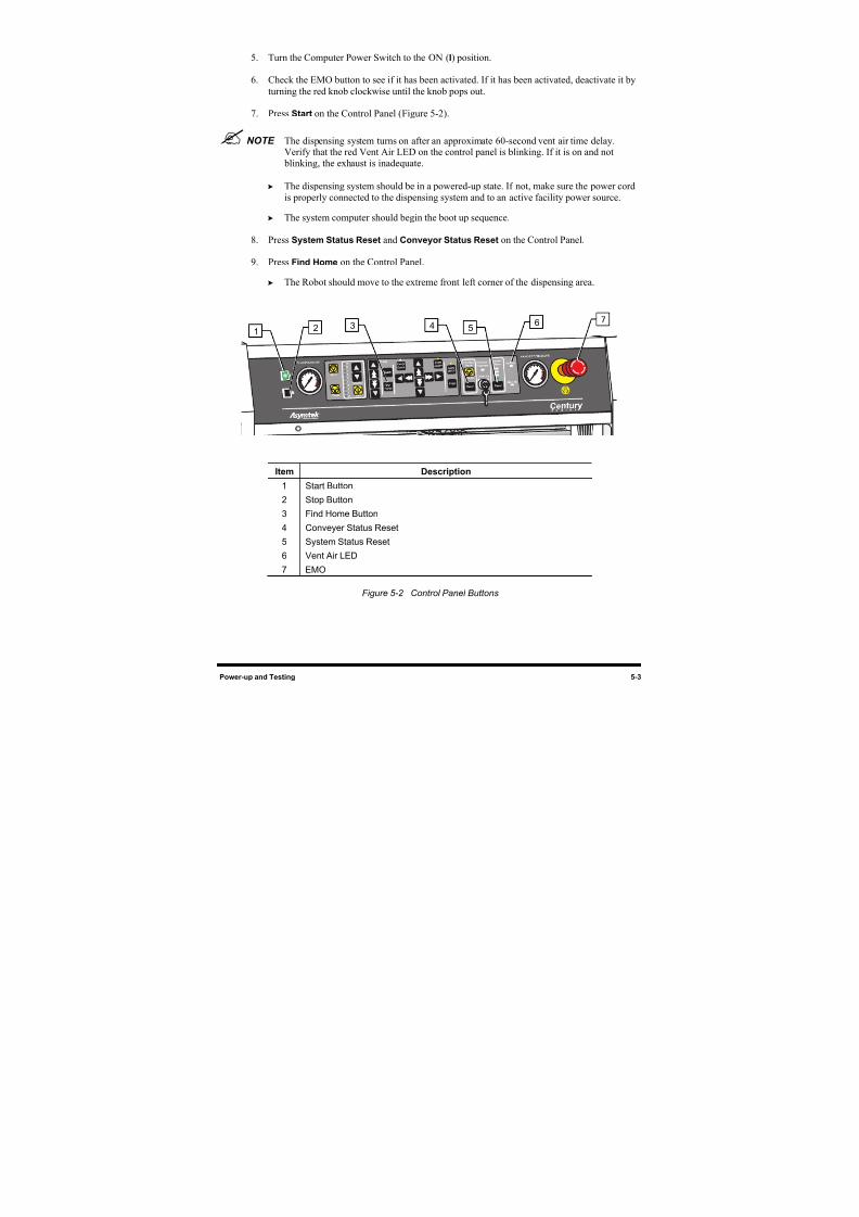
8/16/2019 Dispensig c 740 nordson
http://slidepdf.com/reader/full/dispensig-c-740-nordson 97/240
Power-up and Testing 5-3
5. Turn the Computer Power Switch to the ON (I) position.
6. Check the EMO button to see if it has been activated. If it has been activated, deactivate it by
turning the red knob clockwise until the knob pops out.
7. Press Start on the Control Panel (Figure 5-2).
NOTE The dispensing system turns on after an approximate 60-second vent air time delay.
Verify that the red Vent Air LED on the control panel is blinking. If it is on and not blinking, the exhaust is inadequate.
The dispensing system should be in a powered-up state. If not, make sure the power cord
is properly connected to the dispensing system and to an active facility power source.
The system computer should begin the boot up sequence.
8. Press System Status Reset and Conveyor Status Reset on the Control Panel.
9. Press Find Home on the Control Panel.
The Robot should move to the extreme front left corner of the dispensing area.
Item Description
1 Start Button
2 Stop Button
3 Find Home Button
4 Conveyer Status Reset
5 System Status Reset
6 Vent Air LED
7 EMO
Figure 5-2 Control Panel Buttons
3 4 57
16
2
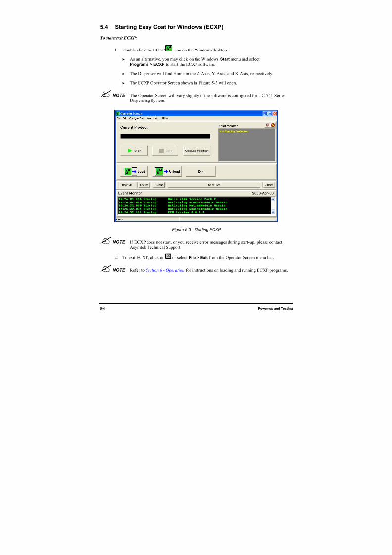
8/16/2019 Dispensig c 740 nordson
http://slidepdf.com/reader/full/dispensig-c-740-nordson 98/240
5-4 Power-up and Testing
5.4 Starting Easy Coat for Windows (ECXP)
To start/exit ECXP:
1. Double click the ECXP icon on the Windows desktop.
As an alternative, you may click on the Windows Start menu and select
Programs > ECXP to start the ECXP software.
The Dispenser will find Home in the Z-Axis, Y-Axis, and X-Axis, respectively.
The ECXP Operator Screen shown in Figure 5-3 will open.
NOTE The Operator Screen will vary slightly if the software is configured for a C-741 SeriesDispensing System.
Figure 5-3 Starting ECXP
NOTE If ECXP does not start, or you receive error messages during start-up, please contactAsymtek Technical Support.
2. To exit ECXP, click on or select File > Exit from the Operator Screen menu bar.
NOTE Refer to Section 6 - Operation for instructions on loading and running ECXP programs.
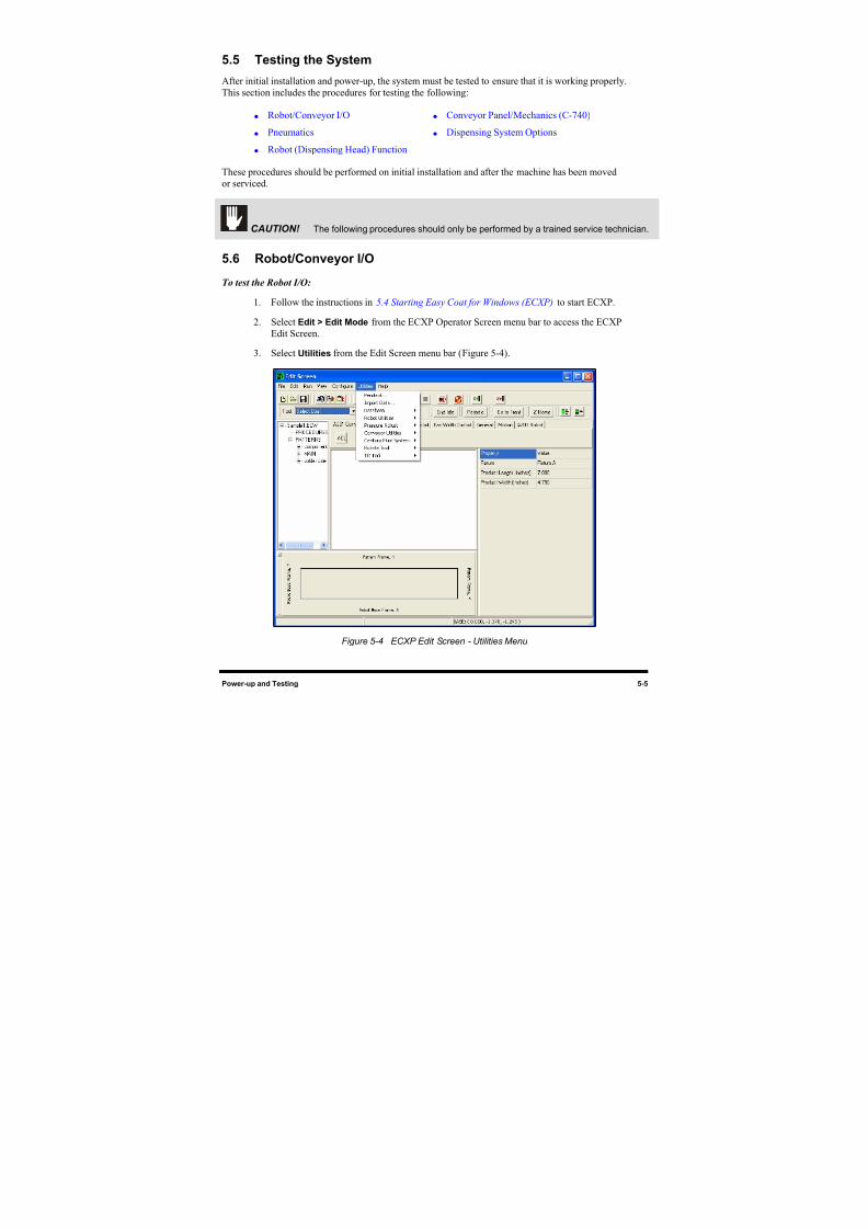
8/16/2019 Dispensig c 740 nordson
http://slidepdf.com/reader/full/dispensig-c-740-nordson 99/240
Power-up and Testing 5-5
5.5 Testing the System
After initial installation and power-up, the system must be tested to ensure that it is working properly.
This section includes the procedures for testing the following:
Robot/Conveyor I/O Conveyor Panel/Mechanics (C-740)
Pneumatics Dispensing System Options
Robot (Dispensing Head) Function
These procedures should be performed on initial installation and after the machine has been moved
or serviced.
CAUTION! The following procedures should only be performed by a trained service technician.
5.6 Robot/Conveyor I/O
To test the Robot I/O:
1. Follow the instructions in 5.4 Starting Easy Coat for Windows (ECXP) to start ECXP.
2. Select Edit > Edit Mode from the ECXP Operator Screen menu bar to access the ECXP
Edit Screen.
3. Select Utilities from the Edit Screen menu bar (Figure 5-4).
Figure 5-4 ECXP Edit Screen - Utilities Menu
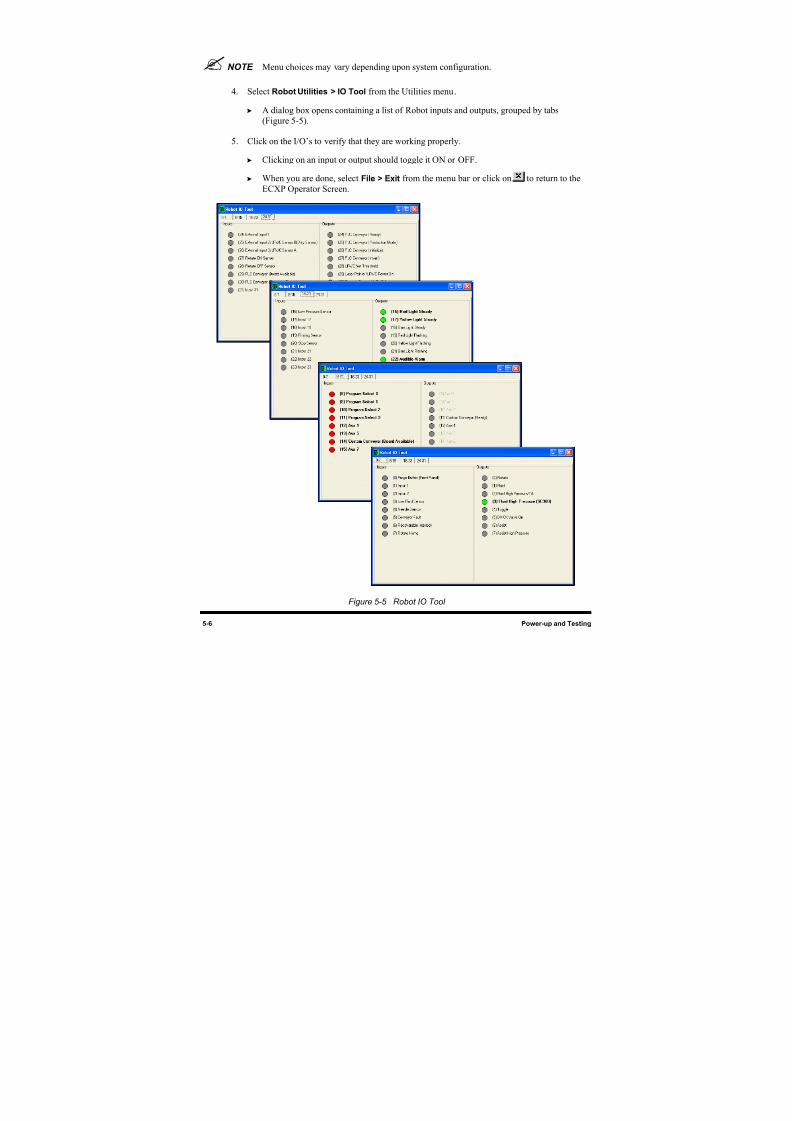
8/16/2019 Dispensig c 740 nordson
http://slidepdf.com/reader/full/dispensig-c-740-nordson 100/240
5-6 Power-up and Testing
NOTE Menu choices may vary depending upon system configuration.
4. Select Robot Utilities > IO Tool from the Utilities menu.
A dialog box opens containing a list of Robot inputs and outputs, grouped by tabs
(Figure 5-5).
5. Click on the I/O’s to verify that they are working properly.
Clicking on an input or output should toggle it ON or OFF.
When you are done, select File > Exit from the menu bar or click on to return to the
ECXP Operator Screen.
Figure 5-5 Robot IO Tool
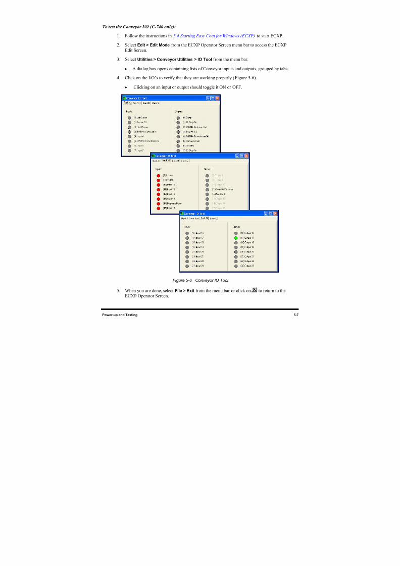
8/16/2019 Dispensig c 740 nordson
http://slidepdf.com/reader/full/dispensig-c-740-nordson 101/240
Power-up and Testing 5-7
To test the Conveyor I/O (C-740 only):
1. Follow the instructions in 5.4 Starting Easy Coat for Windows (ECXP) to start ECXP.
2. Select Edit > Edit Mode from the ECXP Operator Screen menu bar to access the ECXP
Edit Screen.
3. Select Utilities > Conveyor Utilities > IO Tool from the menu bar.
A dialog box opens containing lists of Conveyor inputs and outputs, grouped by tabs.
4. Click on the I/O’s to verify that they are working properly (Figure 5-6).
Clicking on an input or output should toggle it ON or OFF.
Figure 5-6 Conveyor IO Tool
5. When you are done, select File > Exit from the menu bar or click on to return to the
ECXP Operator Screen.
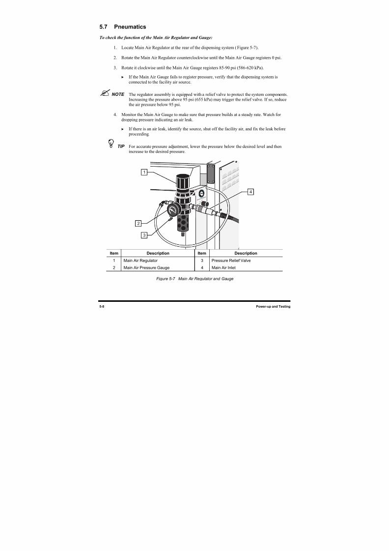
8/16/2019 Dispensig c 740 nordson
http://slidepdf.com/reader/full/dispensig-c-740-nordson 102/240
5-8 Power-up and Testing
5.7 Pneumatics
To check the function of the Main Air Regulator and Gauge:
1. Locate Main Air Regulator at the rear of the dispensing system (Figure 5-7).
2. Rotate the Main Air Regulator counterclockwise until the Main Air Gauge registers 0 psi.
3. Rotate it clockwise until the Main Air Gauge registers 85-90 psi (586-620 kPa).
If the Main Air Gauge fails to register pressure, verify that the dispensing system is
connected to the facility air source.
NOTE The regulator assembly is equipped with a relief valve to protect the system components.Increasing the pressure above 95 psi (655 kPa) may trigger the relief valve. If so, reducethe air pressure below 95 psi.
4. Monitor the Main Air Gauge to make sure that pressure builds at a steady rate. Watch for
dropping pressure indicating an air leak.
If there is an air leak, identify the source, shut off the facility air, and fix the leak before
proceeding.
TIP For accurate pressure adjustment, lower the pressure below the desired level and thenincrease to the desired pressure.
Item Description Item Description
1 Main Air Regulator 3 Pressure Relief Valve
2 Main Air Pressure Gauge 4 Main Air Inlet
Figure 5-7 Main Air Regulator and Gauge
1
4
2
3
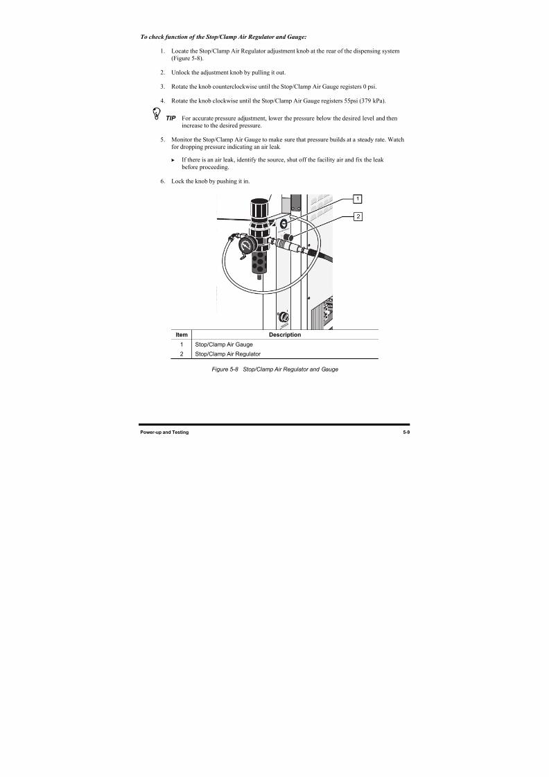
8/16/2019 Dispensig c 740 nordson
http://slidepdf.com/reader/full/dispensig-c-740-nordson 103/240
Power-up and Testing 5-9
To check function of the Stop/Clamp Air Regulator and Gauge:
1. Locate the Stop/Clamp Air Regulator adjustment knob at the rear of the dispensing system
(Figure 5-8).
2. Unlock the adjustment knob by pulling it out.
3. Rotate the knob counterclockwise until the Stop/Clamp Air Gauge registers 0 psi.
4. Rotate the knob clockwise until the Stop/Clamp Air Gauge registers 55psi (379 kPa).
TIP For accurate pressure adjustment, lower the pressure below the desired level and thenincrease to the desired pressure.
5. Monitor the Stop/Clamp Air Gauge to make sure that pressure builds at a steady rate. Watch
for dropping pressure indicating an air leak.
If there is an air leak, identify the source, shut off the facility air and fix the leak
before proceeding.
6. Lock the knob by pushing it in.
Item Description
1 Stop/Clamp Air Gauge
2 Stop/Clamp Air Regulator
Figure 5-8 Stop/Clamp Air Regulator and Gauge
1
2
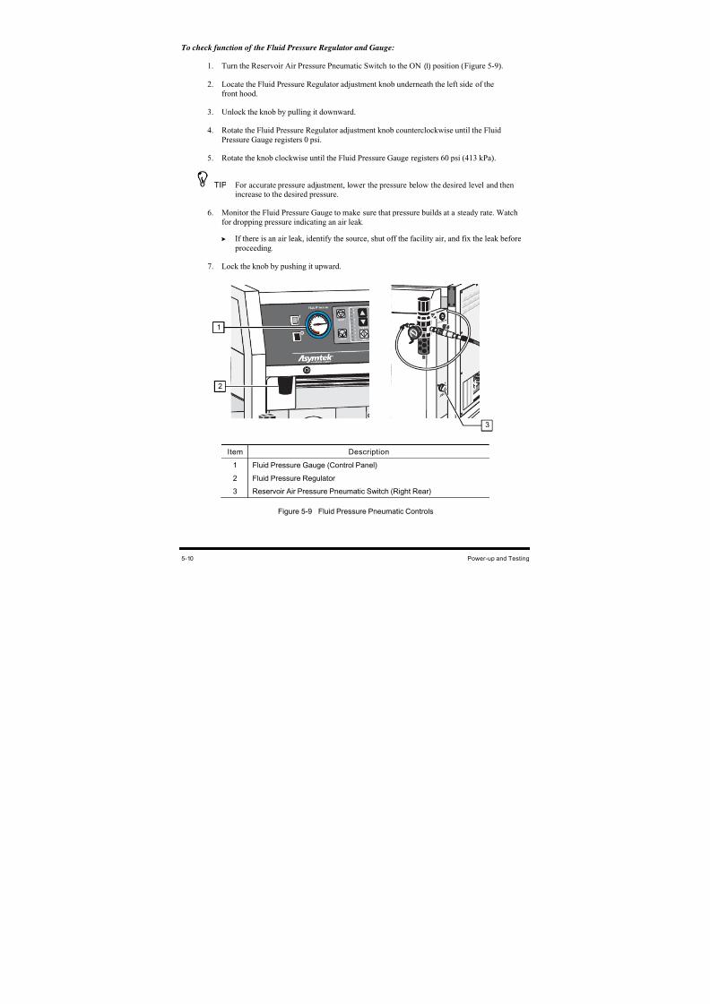
8/16/2019 Dispensig c 740 nordson
http://slidepdf.com/reader/full/dispensig-c-740-nordson 104/240
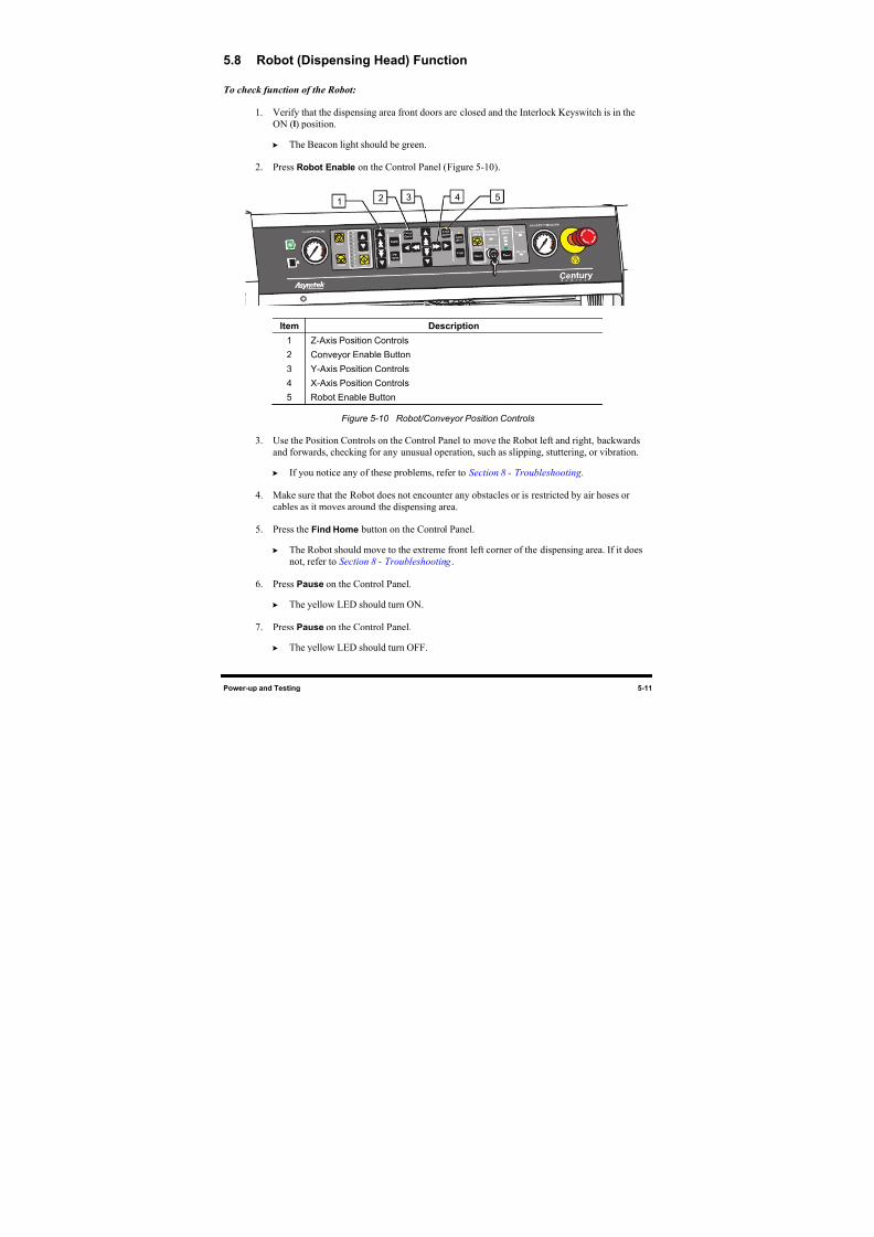
8/16/2019 Dispensig c 740 nordson
http://slidepdf.com/reader/full/dispensig-c-740-nordson 105/240
Power-up and Testing 5-11
5.8 Robot (Dispensing Head) Function
To check function of the Robot:
1. Verify that the dispensing area front doors are closed and the Interlock Keyswitch is in the
ON (I) position.
The Beacon light should be green.
2. Press Robot Enable on the Control Panel (Figure 5-10).
Item Description
1 Z-Axis Position Controls
2 Conveyor Enable Button
3 Y-Axis Position Controls
4 X-Axis Position Controls
5 Robot Enable Button
Figure 5-10 Robot/Conveyor Position Controls
3. Use the Position Controls on the Control Panel to move the Robot left and right, backwards
and forwards, checking for any unusual operation, such as slipping, stuttering, or vibration.
If you notice any of these problems, refer to Section 8 - Troubleshooting .
4. Make sure that the Robot does not encounter any obstacles or is restricted by air hoses or
cables as it moves around the dispensing area.
5. Press the Find Home button on the Control Panel.
The Robot should move to the extreme front left corner of the dispensing area. If it does
not, refer to Section 8 - Troubleshooting .
6. Press Pause on the Control Panel.
The yellow LED should turn ON.
7. Press Pause on the Control Panel.
The yellow LED should turn OFF.
3214 5
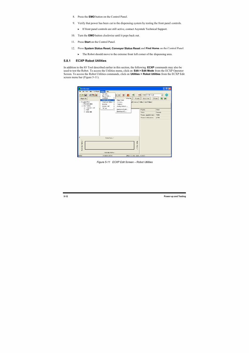
8/16/2019 Dispensig c 740 nordson
http://slidepdf.com/reader/full/dispensig-c-740-nordson 106/240
5-12 Power-up and Testing
8. Press the EMO button on the Control Panel.
9. Verify that power has been cut to the dispensing system by testing the front panel controls.
If front panel controls are still active, contact Asymtek Technical Support.
10. Turn the EMO button clockwise until it pops back out.
11. Press Start on the Control Panel.
12. Press System Status Reset, Conveyer Status Reset and Find Home on the Control Panel.
The Robot should move to the extreme front left corner of the dispensing area.
5.8.1 ECXP Robot Utilities
In addition to the IO Tool described earlier in this section, the following ECXP commands may also be
used to test the Robot. To access the Utilities menu, click on Edit > Edit Mode from the ECXP Operator
Screen. To access the Robot Utilities commands, click on Utilities > Robot Utilities from the ECXP Edit
screen menu bar (Figure 5-11).
Figure 5-11 ECXP Edit Screen – Robot Utilities
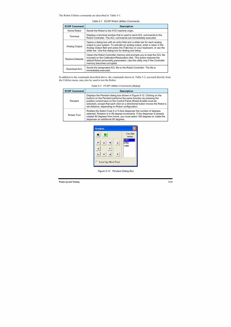
8/16/2019 Dispensig c 740 nordson
http://slidepdf.com/reader/full/dispensig-c-740-nordson 107/240
Power-up and Testing 5-13
The Robot Utilities commands are described in Table 5-1.
Table 5-1 ECXP Robot Utilities Commands
ECXP Command Description
Home Robot Sends the Robot to the XYZ machine origin.
TerminalDisplays a terminal window that is used to send ACL commands to theRobot Controller. The ACL commands are immediately executed.
Analog Output
Opens a dialog box with an entry field and a slider bar for each analogoutput in your system. To activate an analog output, enter a value in the
Analog Output field and press the [Tab] key on your keyboard, or use theslider bar. Use this dialog box for testing and setup.
Restore Defaults
Clears the Robot Controller memory and prompts you to load the ACL fileincluded on the Calibration/Restoration disk. This action restores thedefault Robot personality parameters. Use this utility only if the Controllermemory becomes corrupted.
Download ACLSends the designated ACL file to the Robot Controller. The file isimmediately executed.
In addition to the commands described above, the commands shown in Table 5-2, accessed directly from
the Utilities menu, may also be used to test the Robot.
Table 5-2 ECXP Utilities Commands (Robot)
ECXP Command Description
Pendant
Displays the Pendant dialog box shown in Figure 5-12. Clicking on thebuttons on the Pendant performs the same function as pressing theposition control keys on the Control Panel (Robot Enable must beselected), except that each click on a directional button moves the Robot aset distance, depending on Robot configuration.
Rotate Tool
Rotates the Select Coat 4 or 5-Axis dispenser the number of degreesselected. Rotation is in 90-degree increments. If the dispenser is alreadyrotated 90 degrees from home, you must select 180 degrees to rotate thedispenser an additional 90 degrees.
Figure 5-12 Pendant Dialog Box
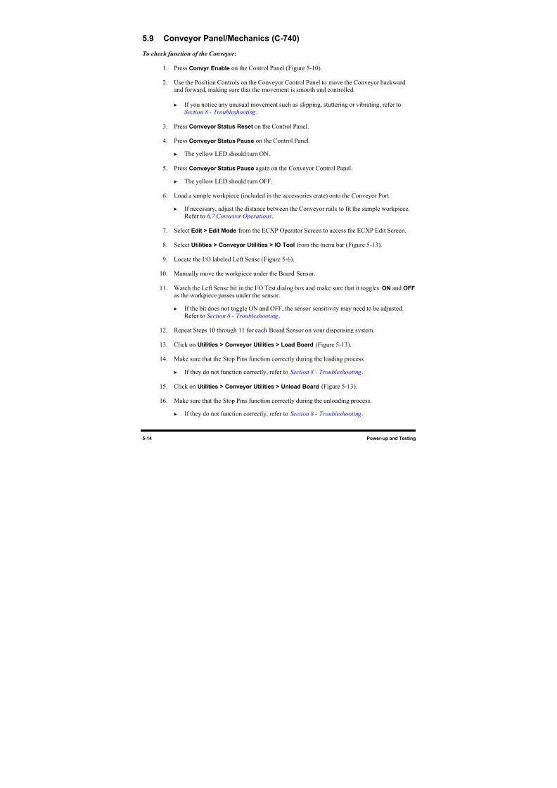
8/16/2019 Dispensig c 740 nordson
http://slidepdf.com/reader/full/dispensig-c-740-nordson 108/240
5-14 Power-up and Testing
5.9 Conveyor Panel/Mechanics (C-740)
To check function of the Conveyor:
1. Press Convyr Enable on the Control Panel (Figure 5-10).
2. Use the Position Controls on the Conveyor Control Panel to move the Conveyor backward
and forward, making sure that the movement is smooth and controlled.
If you notice any unusual movement such as slipping, stuttering or vibrating, refer to
Section 8 - Troubleshooting .
3. Press Conveyor Status Reset on the Control Panel.
4. Press Conveyor Status Pause on the Control Panel.
The yellow LED should turn ON.
5. Press Conveyor Status Pause again on the Conveyor Control Panel.
The yellow LED should turn OFF.
6. Load a sample workpiece (included in the accessories crate) onto the Conveyor Port.
If necessary, adjust the distance between the Conveyor rails to fit the sample workpiece.
Refer to 6.7 Conveyor Operations.
7. Select Edit > Edit Mode from the ECXP Operator Screen to access the ECXP Edit Screen.
8. Select Utilities > Conveyor Utilities > IO Tool from the menu bar (Figure 5-13).
9. Locate the I/O labeled Left Sense (Figure 5-6).
10. Manually move the workpiece under the Board Sensor.
11. Watch the Left Sense bit in the I/O Test dialog box and make sure that it toggles ON and OFF
as the workpiece passes under the sensor.
If the bit does not toggle ON and OFF, the sensor sensitivity may need to be adjusted.
Refer to Section 8 - Troubleshooting .
12. Repeat Steps 10 through 11 for each Board Sensor on your dispensing system.
13. Click on Utilities > Conveyor Utilities > Load Board (Figure 5-13).
14. Make sure that the Stop Pins function correctly during the loading process.
If they do not function correctly, refer to Section 8 - Troubleshooting .
15. Click on Utilities > Conveyor Utilities > Unload Board (Figure 5-13).
16. Make sure that the Stop Pins function correctly during the unloading process.
If they do not function correctly, refer to Section 8 - Troubleshooting .
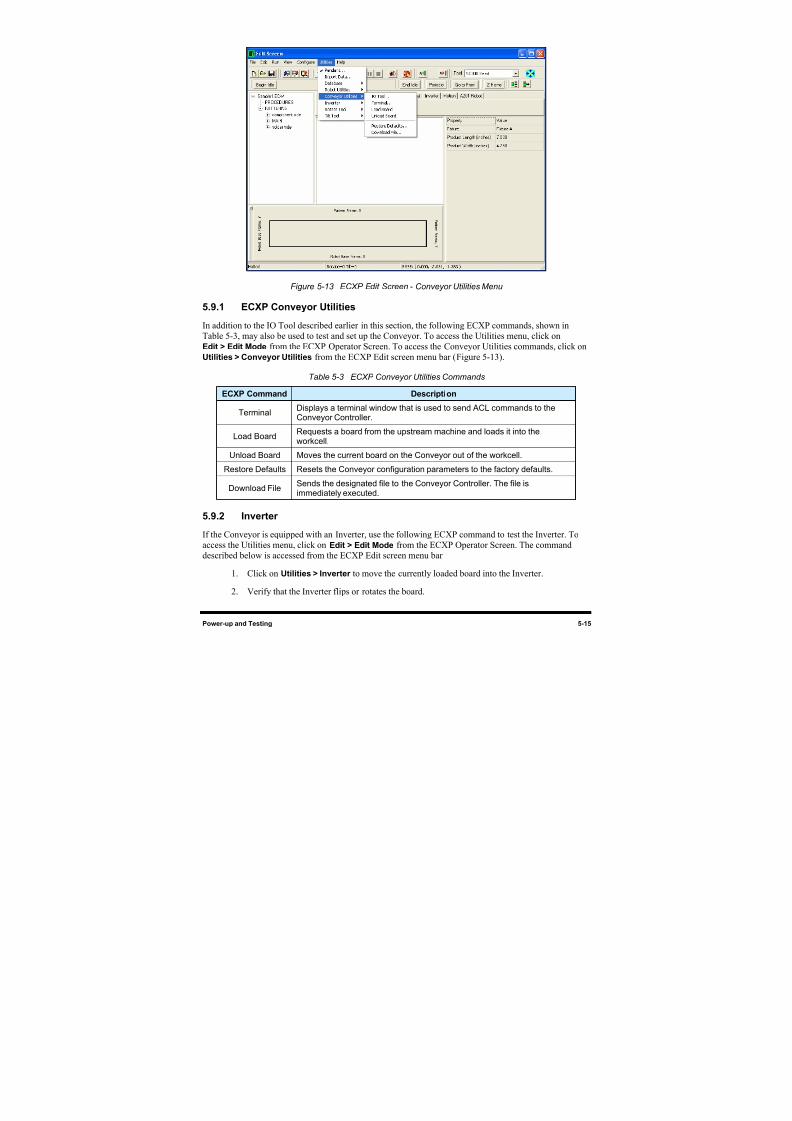
8/16/2019 Dispensig c 740 nordson
http://slidepdf.com/reader/full/dispensig-c-740-nordson 109/240
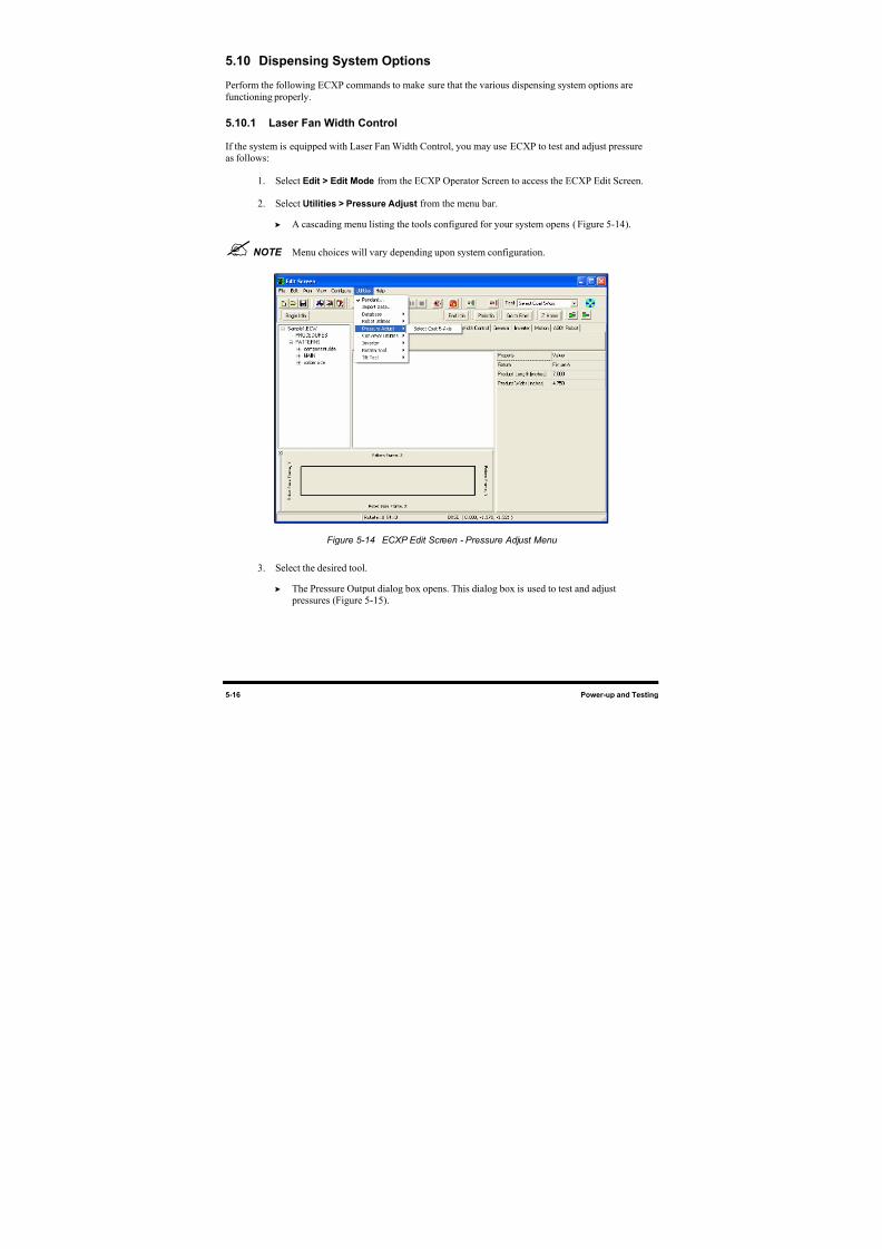
8/16/2019 Dispensig c 740 nordson
http://slidepdf.com/reader/full/dispensig-c-740-nordson 110/240
5-16 Power-up and Testing
5.10 Dispensing System Options
Perform the following ECXP commands to make sure that the various dispensing system options are
functioning properly.
5.10.1 Laser Fan Width Control
If the system is equipped with Laser Fan Width Control, you may use ECXP to test and adjust pressure
as follows:
1. Select Edit > Edit Mode from the ECXP Operator Screen to access the ECXP Edit Screen.
2. Select Utilities > Pressure Adjust from the menu bar.
A cascading menu listing the tools configured for your system opens (Figure 5-14).
NOTE Menu choices will vary depending upon system configuration.
Figure 5-14 ECXP Edit Screen - Pressure Adjust Menu
3. Select the desired tool.
The Pressure Output dialog box opens. This dialog box is used to test and adjust
pressures (Figure 5-15).
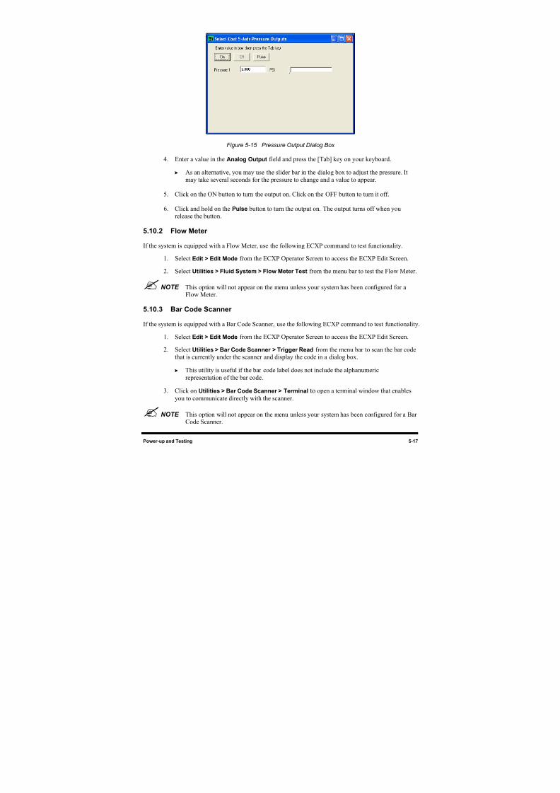
8/16/2019 Dispensig c 740 nordson
http://slidepdf.com/reader/full/dispensig-c-740-nordson 111/240
Power-up and Testing 5-17
Figure 5-15 Pressure Output Dialog Box
4. Enter a value in the Analog Output field and press the [Tab] key on your keyboard.
As an alternative, you may use the slider bar in the dialog box to adjust the pressure. It
may take several seconds for the pressure to change and a value to appear.
5. Click on the ON button to turn the output on. Click on the OFF button to turn it off.
6. Click and hold on the Pulse button to turn the output on. The output turns off when you
release the button.
5.10.2 Flow Meter
If the system is equipped with a Flow Meter, use the following ECXP command to test functionality.
1. Select Edit > Edit Mode from the ECXP Operator Screen to access the ECXP Edit Screen.
2. Select Utilities > Fluid System > Flow Meter Test from the menu bar to test the Flow Meter.
NOTE This option will not appear on the menu unless your system has been configured for aFlow Meter.
5.10.3 Bar Code Scanner
If the system is equipped with a Bar Code Scanner, use the following ECXP command to test functionality.
1. Select Edit > Edit Mode from the ECXP Operator Screen to access the ECXP Edit Screen.
2. Select Utilities > Bar Code Scanner > Trigger Read from the menu bar to scan the bar code
that is currently under the scanner and display the code in a dialog box.
This utility is useful if the bar code label does not include the alphanumeric
representation of the bar code.
3. Click on Utilities > Bar Code Scanner > Terminal to open a terminal window that enables
you to communicate directly with the scanner.
NOTE This option will not appear on the menu unless your system has been configured for a BarCode Scanner.

8/16/2019 Dispensig c 740 nordson
http://slidepdf.com/reader/full/dispensig-c-740-nordson 112/240
8/16/2019 Dispensig c 740 nordson
http://slidepdf.com/reader/full/dispensig-c-740-nordson 113/240
Operation 6-1
6 Operation
6.1 Overview
Before operating your Century C-740/C-741 Dispensing System, it may be helpful to familiarize yourselfwith the basics of how the system works. This section covers the following topics:
• Basic System Operation • Dispensing System Controls
• Conformal Coating • Pneumatic Regulators and Gauges
• Detailed Operation • System Startup/Shutdown
• Computer System • Conformal Coating Setup Procedures
• ECXP Software • Loading a Program
• Dispensing Operations • Running a Program
• Conveyor Operations • Production Statistics
NOTE In this section, typical Century C-740/C-741 configurations are considered. However,operational details may vary with the configuration of your system.
6.2 Basic System Operation
The C-740/C-741 Series Dispensing Systems provide consistent, uniform dispensing of solvent-based and
100-percent solids materials for both inline (C-740) and batch (C-741) coating applications. Easy Coat for
Windows XP (ECXP) software controls both the robot movements and the dispensing operation.
The C-740 has a chain conveyor, which carries the workpiece from an upstream machine, to a dispensing
station where fluid is dispensed, and then delivers the processed workpiece to a downstream machine.
Instead of the conveyor, the C-741 batch dispensing system includes an aluminum tooling plate oradjustable tooling rails. The tooling plate is easily removed for modification. Workpiece fixturing is
customer-supplied. The adjustable tooling rail option is ready to accept boards with a 3mm or greater
edge clearance.
6.3 Conformal Coating
The Century C-740/C-741 Series Dispensing System is designed to apply conformal coating materials
with a high level of flexibility and consistency. Conformal coating is a material that is applied to a circuit
board to provide protection from chemical and mechanical damage.
Applying conformal coating is a two-step process. Dispensing the conformal coating is the first step.
After the conformal coating has been applied, it must be cured. The curing method depends on the coating
material. Most materials are cured by one of the following processes:
• Heat (infrared), using an infrared or convection oven
• UV (ultraviolet) light, using a UV oven
• Moisture (humidity), using ambient conditions or a humidity controlled environment
8/16/2019 Dispensig c 740 nordson
http://slidepdf.com/reader/full/dispensig-c-740-nordson 114/240
6-2 Operation
6.4 Detailed Operation (C-740)
During operational setup of the C-740 inline system, the part enters the system using SMEMA (Surface
Mount Equipment Manufacturers Association) handshakes. It moves to the dispensing area where the
conformal coating is applied and then exits the system. Conformal coating application programs are
created using the Easy Coat for Windows XP (ECXP) software installed on the system.
6.4.1 Dispensing Process
A typical C-740 (conveyorized) conformal coating process is described below. See Figure 6-1 for
additional details. Setup and programming procedures are not included in the description.
1. A part enters the system from an upstream system.
A SMEMA handshake with upstream machine signals dispensing system is ready for a workpiece.
The (standard) chain conveyor carries the board by the edges into the dispensing area. A stop pin
engages to stop the board.
2. The part stops in the Dispensing Area.
A photoelectric sensor detects the presence of the board. The conveyor indexes the part according to
SMEMA standards. Pneumatically actuated board pins lower into holes in the board to secure it
precisely in place for accurate fluid dispensing.
3. Fluid is dispensed.
The conformal coating fluid is applied to the board, according to a preprogrammed dispensing
pattern. Refer to the Easy Coat for Windows User Guide for detailed information.
4. The part moves to a downstream system.
When dispensing is complete, the stop pin disengages, a SMEMA handshake occurs, and the partmoves to the downstream system. Another part is loaded and carried into the dispensing area.
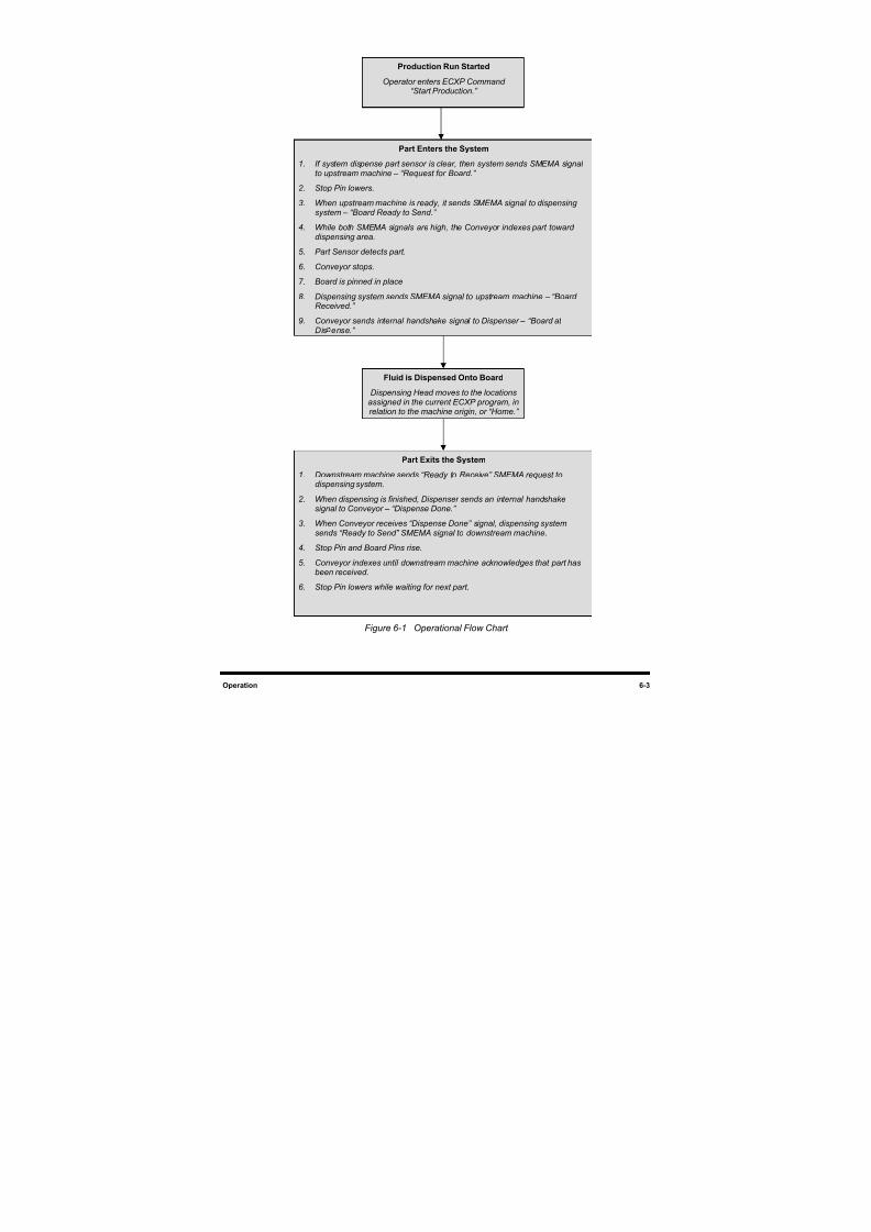
8/16/2019 Dispensig c 740 nordson
http://slidepdf.com/reader/full/dispensig-c-740-nordson 115/240
Operation 6-3
Figure 6-1 Operational Flow Chart
Production Run Started
Operator enters ECXP Command“Start Production.”
Part Enters the System
1. If system dispense part sensor is clear, then system sends SMEMA signalto upstream machine – “Request for Board.”
2. Stop Pin lowers.
3. When upstream machine is ready, it sends SMEMA signal to dispensingsystem – “Board Ready to Send.”
4. While both SMEMA signals are high, the Conveyor indexes part towarddispensing area.
5. Part Sensor detects part.
6. Conveyor stops.
7. Board is pinned in place
8. Dispensing system sends SMEMA signal to upstream machine – “BoardReceived.”
9. Conveyor sends internal handshake signal to Dispenser – “Board atDis ense.”
Fluid is Dispensed Onto Board
Dispensing Head moves to the locationsassigned in the current ECXP program, inrelation to the machine origin, or “Home.”
Part Exits the System
1. Downstream machine sends “Ready to Receive” SMEMA request todispensing system.
2. When dispensing is finished, Dispenser sends an internal handshakesignal to Conveyor – “Dispense Done.”
3. When Conveyor receives “Dispense Done” signal, dispensing systemsends “Ready to Send” SMEMA signal to downstream machine.
4. Stop Pin and Board Pins rise.
5. Conveyor indexes until downstream machine acknowledges that part hasbeen received.
6. Stop Pin lowers while waiting for next part.
8/16/2019 Dispensig c 740 nordson
http://slidepdf.com/reader/full/dispensig-c-740-nordson 116/240
6-4 Operation
6.5 Computer System
The computer is located inside the lower cabinet. The CD-ROM drive, disk drive, power switch and reset
buttons are located on the front of the computer. Access to connections at the rear of the computer should
be limited to service technicians.
Conformal coating dispensing programs are created using the ECXP software installed in your system.
Dispensing programs are stored on the computer hard drive.
6.5.1 ECXP Software
Easy Coat for Windows XP (ECXP) is Asymtek's proprietary dispensing software for use in a Windows
XP environment. ECXP software is an interface between the user and the Robot Controller/Fluid
Applicator. Before the dispensing process can begin, the ECXP software must be installed and
programmed to perform the necessary procedures.
The software allows the user to develop program files (.ECW file extension), which direct the motion of
the Robot Controller/Fluid Applicator to coat a workpiece. The program files contain all the robot moves
and I/O operations necessary to coat the workpiece. Basically, the dispensing program instructs the
system when, where, and how much fluid to dispense. Refer to 6.10 Conformal Coating Setup Procedures 6.11 Loading a Program, and 6.12 Running a Program for detailed instructions on how to load and run a
dispensing program.
NOTE A workpiece is defined as a board or substrate (PCB, PWB, etc.) or a carrier (pallet, auer boat, lead frame, etc.) to be dispensed upon.
6.5.1.1 Computer Front Panel
Below are functional descriptions of the system computer front panel controls shown in Figure 6-2. The
numbers associated with the descriptions correspond to the callout numbers in the illustration.
1. CD-ROM Drive
Press the button below and to the right of the disk tray to insert or eject a disk.
2. 1.44 MB 3.5-inch Disk Drive
The computer has at least one 3.5-inch, 1.4 MB disk drive. Insert disks through the drive door flap.
Press the small button on the lower right to eject a disk.
3. Power Switch
The power switch turns the computer power ON and OFF.
4. Reset Button
Pressing the Reset button reboots the computer after a system failure.
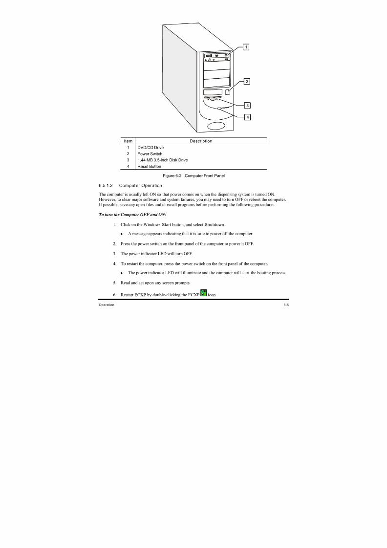
8/16/2019 Dispensig c 740 nordson
http://slidepdf.com/reader/full/dispensig-c-740-nordson 117/240
Operation 6-5
Item Description
1 DVD/CD Drive
2 Power Switch
3 1.44 MB 3.5-inch Disk Drive
4 Reset Button
Figure 6-2 Computer Front Panel
6.5.1.2 Computer Operation
The computer is usually left ON so that power comes on when the dispensing system is turned ON.
However, to clear major software and system failures, you may need to turn OFF or reboot the computer.
If possible, save any open files and close all programs before performing the following procedures.
To turn the Computer OFF and ON:
1. Click on the Windows Start button, and select Shutdown.
A message appears indicating that it is safe to power off the computer.
2. Press the power switch on the front panel of the computer to power it OFF.
3. The power indicator LED will turn OFF.
4. To restart the computer, press the power switch on the front panel of the computer.
The power indicator LED will illuminate and the computer will start the booting process.
5. Read and act upon any screen prompts.
6. Restart ECXP by double-clicking the ECXP icon
2
3
1
4
8/16/2019 Dispensig c 740 nordson
http://slidepdf.com/reader/full/dispensig-c-740-nordson 118/240
6-6 Operation
To reboot the Computer:
1. To reboot the computer, press the Reset button on the front face of the computer.
2. The computer will turn OFF briefly and then back ON, as indicated by the power indicator.
Read and act upon any screen prompts.
3. Restart ECXP by double-clicking the ECXP icon
6.6 Dispensing Operations
All dispensing operations take place in a workcell. The workcell contains a robot and a fluid dispensing
applicator mounted on the robot tool arm.
6.6.1 Robot Concepts
6.6.1.1 Home
The home position of the robot is a known position within the workspace defined by X, Y, and Z
coordinates. It is generally located at the front left of the workcell.
6.6.1.2 Tool
A tool consists of a fluid dispensing applicator and nozzle.
6.6.1.3 Tool Offset
The tool offset is the X, Y, and Z distance from the robot's lower tooling pin to the tool tip (the end of thenozzle). Robot position is calculated using the coordinates of the tooling pin plus the offset. Refer to
7.10 Robot Configuration to establish Tool Offsets.
6.6.1.4 Robot Motion
Robot moves are specified as coordinates on the X, Y or Z-axes. If a move combines motion in all threeaxes, and the Robot Controller cannot move the robot in the Z-axis at the same time as the X and Y-axes,
then the move is performed (depending on the Safe Z Height setting) as follows:
• If the destination is higher than the starting point, the Z motion is performed first.
• If the destination is lower than the starting point, the Z motion is performed last.
6.6.1.5 Fixture
Fixture is defined as the location at which products are physically constrained in the workcell. It consists
of both a position (X, Y, Z) and a corner constraint. Refer to 7.7 Fixture Configuration.
6.6.1.6 Safe Z Height
This is the height below which the tool tip cannot go when moving from one set of coordinates to another
during operation. It prevents the tool tip from colliding with a board component, a fixture, or the
conveyor. The Safe Z Height is set in the ECXP program. Refer to 7.10 Robot Configuration to set the
Safe Z Height.
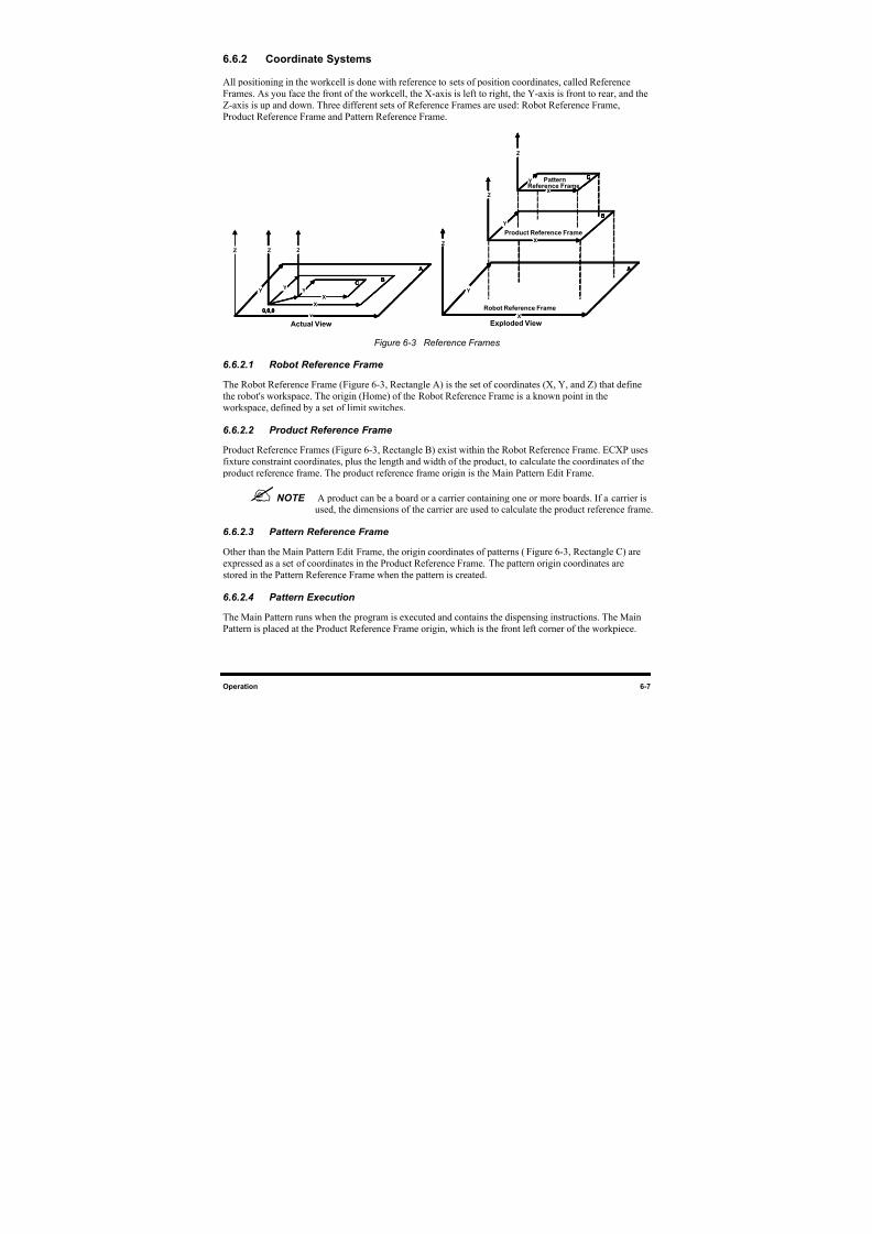
8/16/2019 Dispensig c 740 nordson
http://slidepdf.com/reader/full/dispensig-c-740-nordson 119/240
Operation 6-7
6.6.2 Coordinate Systems
All positioning in the workcell is done with reference to sets of position coordinates, called Reference
Frames. As you face the front of the workcell, the X-axis is left to right, the Y-axis is front to rear, and the
Z-axis is up and down. Three different sets of Reference Frames are used: Robot Reference Frame,
Product Reference Frame and Pattern Reference Frame.
A
X
Y
Z
B
X
Y
Z
C
X
Y
Z
0,0,0
A
X
Y
Z
C
X
Y
Z
B
X
Y
Z
A
X
Y
Z
B
X
Y
Z
C
X
Y
Z
0,0,0
A
X
Y
ZZ
B
X
Y
ZZ
C
X
Y
Z
0,0,0
A
X
Y
Z
C
X
Y
Z
B
X
Y
Z
A
X
Y
Z
A
X
Y
Z
C
X
Y
Z
C
X
Y
Z
C
X
Y
Z
C
X
Y
Z
B
X
Y
Z
B
X
Y
Z
Figure 6-3 Reference Frames
6.6.2.1 Robot Reference Frame
The Robot Reference Frame (Figure 6-3, Rectangle A) is the set of coordinates (X, Y, and Z) that define
the robot's workspace. The origin (Home) of the Robot Reference Frame is a known point in the
workspace, defined by a set of limit switches.
6.6.2.2 Product Reference Frame
Product Reference Frames (Figure 6-3, Rectangle B) exist within the Robot Reference Frame. ECXP uses
fixture constraint coordinates, plus the length and width of the product, to calculate the coordinates of the
product reference frame. The product reference frame origin is the Main Pattern Edit Frame.
NOTE A product can be a board or a carrier containing one or more boards. If a carrier isused, the dimensions of the carrier are used to calculate the product reference frame.
6.6.2.3 Pattern Reference Frame
Other than the Main Pattern Edit Frame, the origin coordinates of patterns (Figure 6-3, Rectangle C) are
expressed as a set of coordinates in the Product Reference Frame. The pattern origin coordinates are
stored in the Pattern Reference Frame when the pattern is created.
6.6.2.4 Pattern Execution
The Main Pattern runs when the program is executed and contains the dispensing instructions. The Main
Pattern is placed at the Product Reference Frame origin, which is the front left corner of the workpiece.
Robot Reference Frame
Product Reference Frame
Reference FramePattern
Actual View Exploded View
8/16/2019 Dispensig c 740 nordson
http://slidepdf.com/reader/full/dispensig-c-740-nordson 120/240
6-8 Operation
6.7 Conveyor Operations
6.7.1 Chain Conveyor (C-740)
The chain conveyor, standard on the Century Series C-740 Dispensing System, transports the workpiece
into and out of the dispensing system. Operation of the conveyor is automatic during production runs. An
optical sensor detects the part as it arrives, triggering the Conveyor Controller Module to activate the Stop
Pin to stop the part at the correct location. Board pins in the dispense zone secure the part in place duringfluid dispensing.
NOTE The C-741 batch system has a tooling plate or adjustable tooling rails to secure theworkpiece for dispensing operations.
6.7.1.1 Conveyor Adjustments
The conveyor should not need adjustment during normal operation. However, during programming, or
when replacing conveyor parts or changing the type/size of the workpiece, you may need to move the
conveyor chain left or right, or adjust the distance between the conveyor rails.
To move the conveyor chain left or right:
1. Press CONVYR ENABLE on the Control Panel.
The conveyor LED blinks when the conveyor control is active.
2. Press the left or right arrow on the Control Panel to move the conveyor chain left or right,respectively.
To manually adjust the distance between conveyor rails:
1. Loosen the Width Adjustment Clamp (Figure 6-4).
2. Manually turn the hand crank clockwise or counterclockwise as needed.
Turning the hand crank clockwise increases the distance between the rails.
Turning the hand crank counterclockwise decreases the distance between the rails.
3. When you are satisfied with the distance between the rails, tighten the Width Adjustment
Clamp.
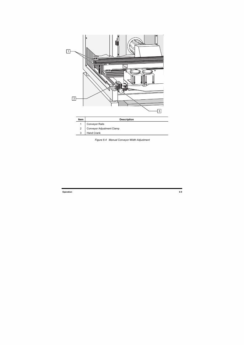
8/16/2019 Dispensig c 740 nordson
http://slidepdf.com/reader/full/dispensig-c-740-nordson 121/240
Operation 6-9
Item Description
1 Conveyor Rails
2 Conveyor Adjustment Clamp
3 Hand Crank
Figure 6-4 Manual Conveyor Width Adjustment
3
2
1
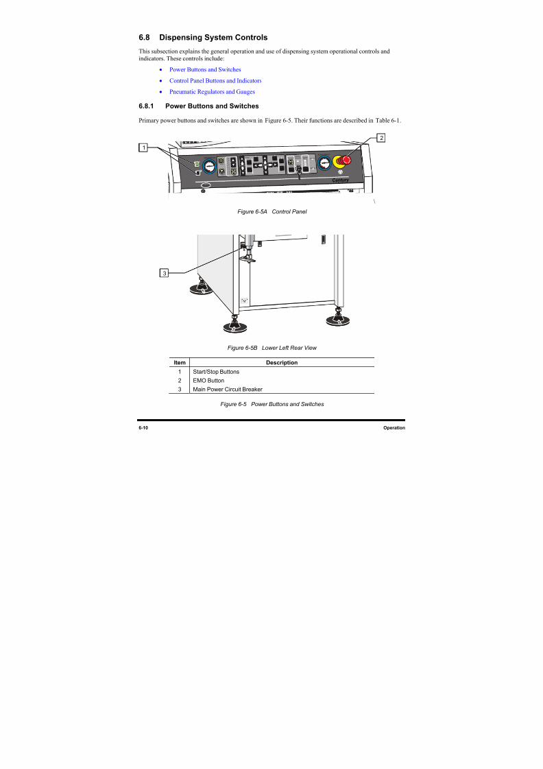
8/16/2019 Dispensig c 740 nordson
http://slidepdf.com/reader/full/dispensig-c-740-nordson 122/240
6-10 Operation
6.8 Dispensing System Controls
This subsection explains the general operation and use of dispensing system operational controls and
indicators. These controls include:
• Power Buttons and Switches
• Control Panel Buttons and Indicators
• Pneumatic Regulators and Gauges
6.8.1 Power Buttons and Switches
Primary power buttons and switches are shown in Figure 6-5. Their functions are described in Table 6-1.
Cent ur y
Valve Pressur e Z Axis
Interlock
Inter lock
Recovery SystemStatus Vent Air
Main Air
Air Assist Pr essure
Reset
S E R I E S
FindHome
Teach
Pause
Conveyor Status
Reset
Pr ogr am
9
8
7
6
5
4
3
2
10
Abor t
St ar t P ause
Conv y r Robot
Appli c
P ur ge
Enable Enable
On / Off
N or d so n
\
Figure 6-5 A Control Panel
Figure 6-5 B Lower Left Rear View
Item Description
1 Start/Stop Buttons
2 EMO Button
3 Main Power Circuit Breaker
Figure 6-5 Power Buttons and Switches
2
1
3
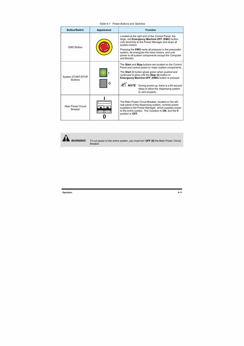
8/16/2019 Dispensig c 740 nordson
http://slidepdf.com/reader/full/dispensig-c-740-nordson 123/240
Operation 6-11
Table 6-1 Power Buttons and Switches
Button/Switch Appearance Function
EMO Button
Located at the right end of the Control Panel, the
large, red Emergency Machine OFF (EMO) buttoncuts electricity to the Power Manager and stops allsystem motion.
Pressing the EMO vents all pressure in the pneumaticsystem, de-energizes the robot motors, and cutspower to all system components except the Computerand Monitor.
System START/STOPButtons
I
The Start and Stop buttons are located on the ControlPanel and control power to major system components.
The Start (I) button glows green when pushed andcontinues to glow until the Stop (0) button or
Emergency Machine OFF (EMO) button is pressed.
NOTE During power-up, there is a 60 second
delay to allow the dispensing system
to vent properly.
Main Power CircuitBreaker
I
0
The Main Power Circuit Breaker, located on the leftrear panel of the dispensing system, controls powersupplied to the Power Manager, which supplies powerto the entire system. The I position is ON, and the 0 position is OFF.
WARNING! To cut power to the entire system, you must turn OFF (0) the Main Power CircuitBreaker.
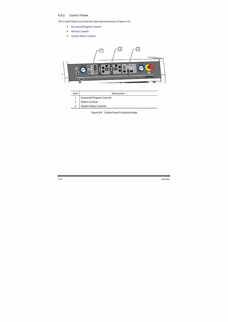
8/16/2019 Dispensig c 740 nordson
http://slidepdf.com/reader/full/dispensig-c-740-nordson 124/240
6-12 Operation
6.8.2 Control Panel
The Control Panel is divided into three functional areas (Figure 6-6):
• Download Program Controls
• Motion Controls
• System Status Controls
Cent ur y
Valve Pr essure Z Axis
Inter lock
Inter lock
Recover y SystemStatus Vent
Air
Main Air
Air Assist Pr essur e
Reset
S E R I E S
FindHome
Teach
Pause
Conv ey or Status
Reset
Pr ogr am
9
8
7
6
5
4
3
2
1
0
Ab o rt
St ar t P ause
Conv y r Robot
Appli c
P ur ge
Enable Enable
On /Of f
N o r d son
Item Description
1 Download Program Controls
2 Motion Controls
3 System Status Controls
Figure 6-6 Control Panel Functional Areas
2 31
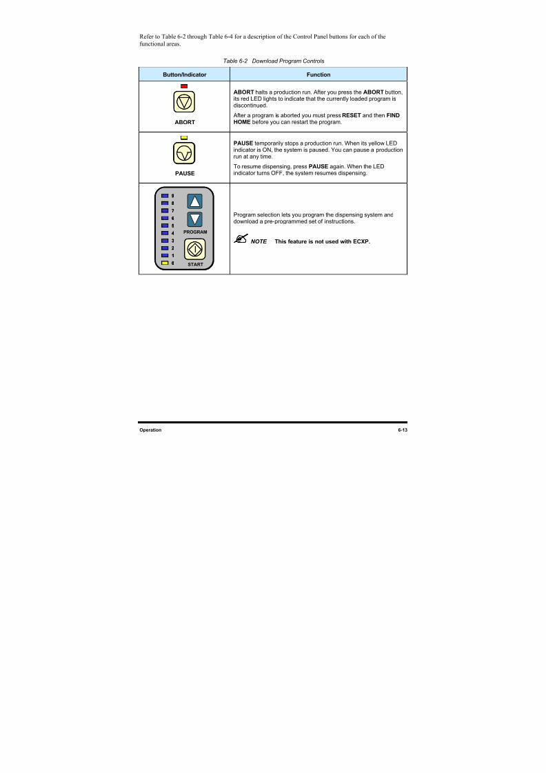
8/16/2019 Dispensig c 740 nordson
http://slidepdf.com/reader/full/dispensig-c-740-nordson 125/240
Operation 6-13
Refer to Table 6-2 through Table 6-4 for a description of the Control Panel buttons for each of the
functional areas.
Table 6-2 Download Program Controls
Button/Indicator Function
ABORT
ABORT halts a production run. After you press the ABORT button,its red LED lights to indicate that the currently loaded program isdiscontinued.
After a program is aborted you must press RESET and then FINDHOME before you can restart the program.
VVV
PAUSE
PAUSE temporarily stops a production run. When its yellow LEDindicator is ON, the system is paused. You can pause a productionrun at any time.
To resume dispensing, press PAUSE again. When the LED
indicator turns OFF, the system resumes dispensing.
9
8
7
6
5
3
2
1
4
0 START
PROGRAM
9
8
7
6
5
3
2
1
4
0
9
8
7
6
5
3
2
1
4
0 START
PROGRAM
Program selection lets you program the dispensing system anddownload a pre-programmed set of instructions.
NOTE This feature is not used with ECXP.
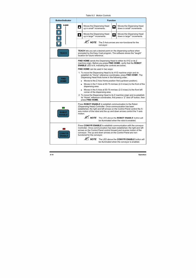
8/16/2019 Dispensig c 740 nordson
http://slidepdf.com/reader/full/dispensig-c-740-nordson 126/240
6-14 Operation
Table 6-3 Motion Controls
Button/Indicator Function
Moves the Dispensing Headup in small* increments.
Moves the Dispensing Headdown in small* increments.
Moves the Dispensing Headup in large** increments.
Moves the Dispensing Headdown in large** increments.
Z-AXISZ-AXIS
NOTE The Z-Axis arrows are non-functional for the
conveyor.
TEACH
TEACH lets you set a desired point on the dispensing surface whenprompted by the Easy Coat program. The software stores the “taught”location for future reference.
FIND
HOME
FIND HOME sends the Dispensing Head to either its XYZ or its Z
machine origin. Before you press FIND HOME, verify that the ROBOTENABLE LED is lit, indicating the controls are active.
FIND HOME can be used in two ways:
1. To move the Dispensing Head to its XYZ machine origin and re-establish its “Home” reference coordinates, press FIND HOME. TheDispensing Head finds home in the following order:
Moves to the Z-Axis Home position first (up/down position).
Moves in the Y-Axis at 50-75 mm/sec (2-3 in/sec) to the front of thedispensing area.
Moves in the X-Axis at 50-75 mm/sec (2-3 in/sec) to the front leftcorner of the dispensing area.
2. To move the Dispensing Head to its Z machine origin and re-establishits “Home” reference coordinates, first press a “Z” axis UP button, thenpress FIND HOME.
ROBOT
ENABLE
ROBOT
ENABLE
Press ROBOT ENABLE to establish communication to the Robot(Dispensing Head) Controller. Once communication has beenestablished, the right and left arrows on the Control Panel control the X-axis motion of the robot and the up and down arrows control the Y-axismotion.
NOTE The LED above the ROBOT ENABLE button will
be illuminated when the robot is enabled.
.
CONVYR
ENABLE
CONVYR
ENABLE
Press CONVYR ENABLE to establish communication with the conveyorController. Once communication has been established, the right and leftarrows on the Control Panel control forward and reverse motion of theconveyor. The up and down arrows on the Control Panel are non-functional for the conveyor.
NOTE The LED above the CONVYR ENABLE button will
be illuminated when the conveyor is enabled.
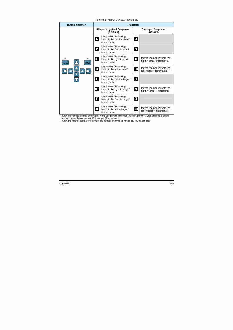
8/16/2019 Dispensig c 740 nordson
http://slidepdf.com/reader/full/dispensig-c-740-nordson 127/240
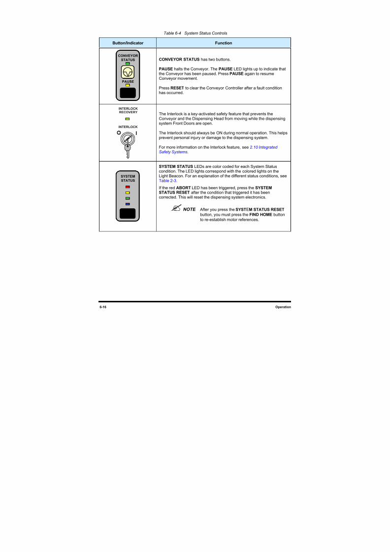
8/16/2019 Dispensig c 740 nordson
http://slidepdf.com/reader/full/dispensig-c-740-nordson 128/240
6-16 Operation
Table 6-4 System Status Controls
Button/Indicator Function
CONVEYOR
STATUS
RESET
VPAUSE
CONVEYOR
STATUS
RESET
VVPAUSE
CONVEYOR STATUS has two buttons.
PAUSE halts the Conveyor. The PAUSE LED lights up to indicate thatthe Conveyor has been paused. Press PAUSE again to resumeConveyor movement.
Press RESET to clear the Conveyor Controller after a fault conditionhas occurred.
INTERLOCK
INTERLOCK
RECOVERY
The Interlock is a key-activated safety feature that prevents theConveyor and the Dispensing Head from moving while the dispensing
system Front Doors are open.
The Interlock should always be ON during normal operation. This helpsprevent personal injury or damage to the dispensing system.
For more information on the Interlock feature, see 2.10 Integrated Safety Systems.
SYSTEM
STATUS
RESET
SYSTEM
STATUS
RESET
SYSTEM STATUS LEDs are color coded for each System Statuscondition. The LED lights correspond with the colored lights on theLight Beacon. For an explanation of the different status conditions, seeTable 2-3.
If the red ABORT LED has been triggered, press the SYSTEMSTATUS RESET after the condition that triggered it has beencorrected. This will reset the dispensing system electronics.
NOTE After you press the SYSTEM STATUS RESET
button, you must press the FIND HOME button
to re-establish motor references.
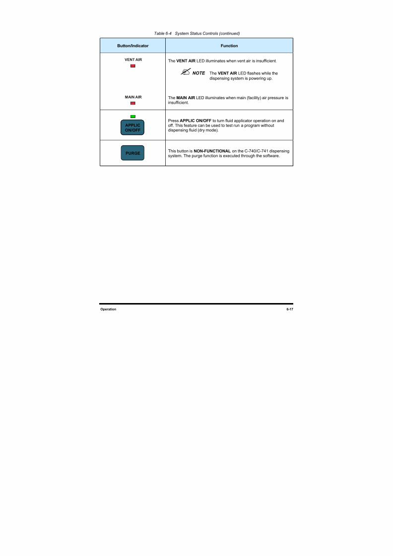
8/16/2019 Dispensig c 740 nordson
http://slidepdf.com/reader/full/dispensig-c-740-nordson 129/240
Operation 6-17
Table 6-4 System Status Controls (continued)
Button/Indicator Function
VENTAIR
MAINAIR
The VENT AIR LED illuminates when vent air is insufficient.
NOTE The VENT AIR LED flashes while the
dispensing system is powering up.
The MAIN AIR LED illuminates when main (facility) air pressure isinsufficient.
APPLICON/OFFAPPLICON/OFF
Press APPLIC ON/OFF to turn fluid applicator operation on and
off. This feature can be used to test run a program withoutdispensing fluid (dry mode).
PURGE
This button is NON-FUNCTIONAL on the C-740/C-741 dispensingsystem. The purge function is executed through the software.
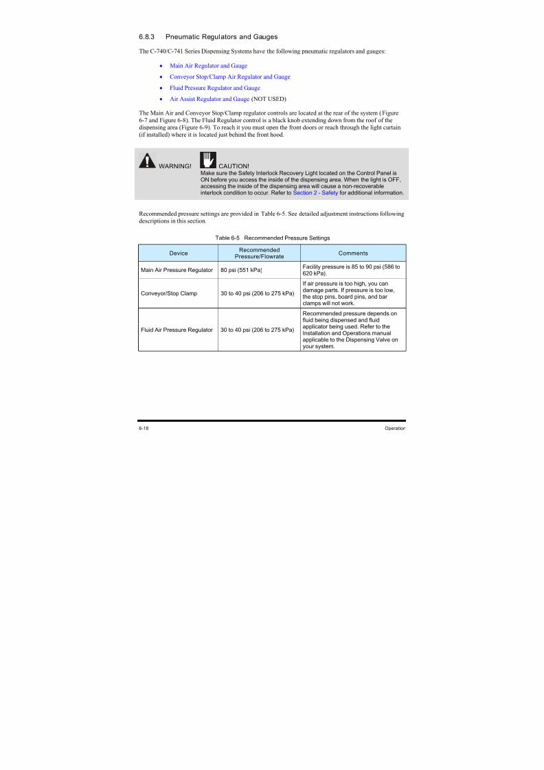
8/16/2019 Dispensig c 740 nordson
http://slidepdf.com/reader/full/dispensig-c-740-nordson 130/240
6-18 Operation
6.8.3 Pneumatic Regulators and Gauges
The C-740/C-741 Series Dispensing Systems have the following pneumatic regulators and gauges:
• Main Air Regulator and Gauge
• Conveyor Stop/Clamp Air Regulator and Gauge
• Fluid Pressure Regulator and Gauge
• Air Assist Regulator and Gauge (NOT USED)
The Main Air and Conveyor Stop/Clamp regulator controls are located at the rear of the system (Figure
6-7 and Figure 6-8). The Fluid Regulator control is a black knob extending down from the roof of the
dispensing area (Figure 6-9). To reach it you must open the front doors or reach through the light curtain
(if installed) where it is located just behind the front hood.
WARNING! CAUTION!
Make sure the Safety Interlock Recovery Light located on the Control Panel isON before you access the inside of the dispensing area. When the light is OFF,accessing the inside of the dispensing area will cause a non-recoverableinterlock condition to occur. Refer to Section 2 - Safety for additional information.
Recommended pressure settings are provided in Table 6-5. See detailed adjustment instructions following
descriptions in this section.
Table 6-5 Recommended Pressure Settings
DeviceRecommended
Pressure/FlowrateComments
Main Air Pressure Regulator 80 psi (551 kPa) Facility pressure is 85 to 90 psi (586 to620 kPa).
Conveyor/Stop Clamp 30 to 40 psi (206 to 275 kPa)
If air pressure is too high, you candamage parts. If pressure is too low,the stop pins, board pins, and barclamps will not work.
Fluid Air Pressure Regulator 30 to 40 psi (206 to 275 kPa)
Recommended pressure depends onfluid being dispensed and fluidapplicator being used. Refer to theInstallation and Operations manualapplicable to the Dispensing Valve on
your system.
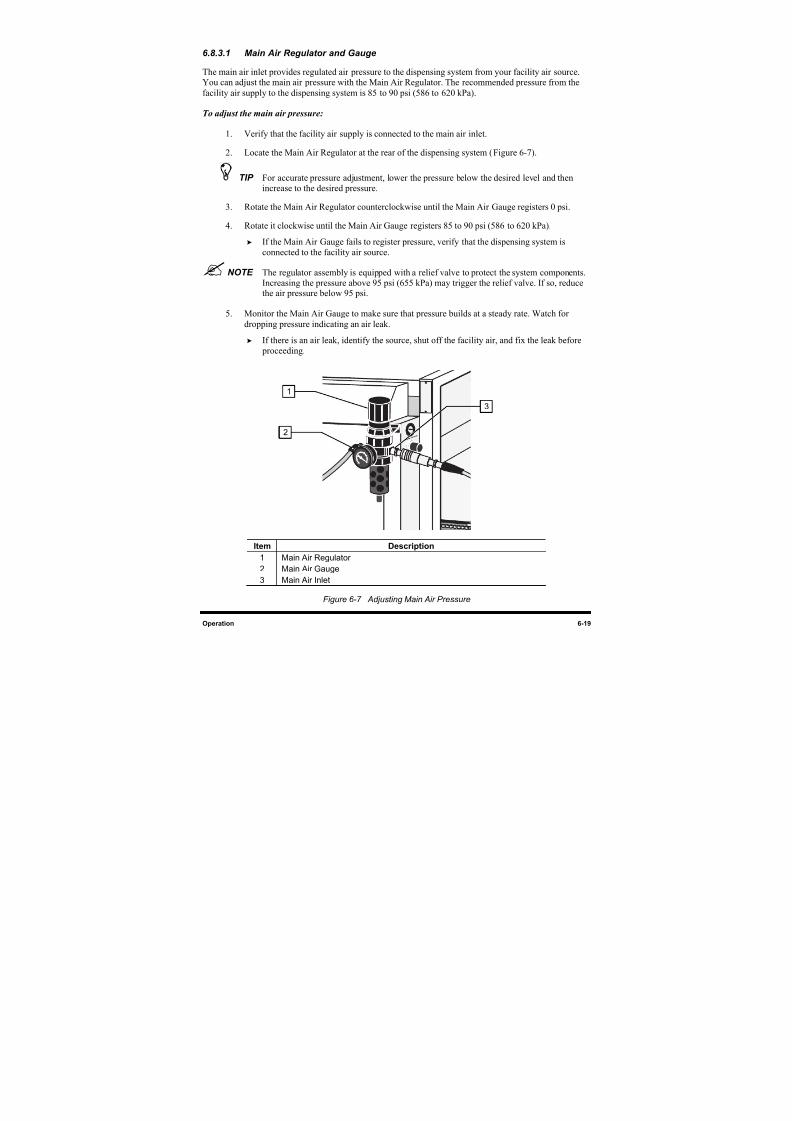
8/16/2019 Dispensig c 740 nordson
http://slidepdf.com/reader/full/dispensig-c-740-nordson 131/240
Operation 6-19
6.8.3.1 Main Air Regulator and Gauge
The main air inlet provides regulated air pressure to the dispensing system from your facility air source.You can adjust the main air pressure with the Main Air Regulator. The recommended pressure from the
facility air supply to the dispensing system is 85 to 90 psi (586 to 620 kPa).
To adjust the main air pressure:
1. Verify that the facility air supply is connected to the main air inlet.
2. Locate the Main Air Regulator at the rear of the dispensing system (Figure 6-7).
TIP For accurate pressure adjustment, lower the pressure below the desired level and thenincrease to the desired pressure.
3. Rotate the Main Air Regulator counterclockwise until the Main Air Gauge registers 0 psi.
4. Rotate it clockwise until the Main Air Gauge registers 85 to 90 psi (586 to 620 kPa).
If the Main Air Gauge fails to register pressure, verify that the dispensing system is
connected to the facility air source.
NOTE The regulator assembly is equipped with a relief valve to protect the system components.Increasing the pressure above 95 psi (655 kPa) may trigger the relief valve. If so, reducethe air pressure below 95 psi.
5. Monitor the Main Air Gauge to make sure that pressure builds at a steady rate. Watch for
dropping pressure indicating an air leak.
If there is an air leak, identify the source, shut off the facility air, and fix the leak before
proceeding.
Item Description
1 Main Air Regulator
2 Main Air Gauge
3 Main Air Inlet
Figure 6-7 Adjusting Main Air Pressure
1
2
3
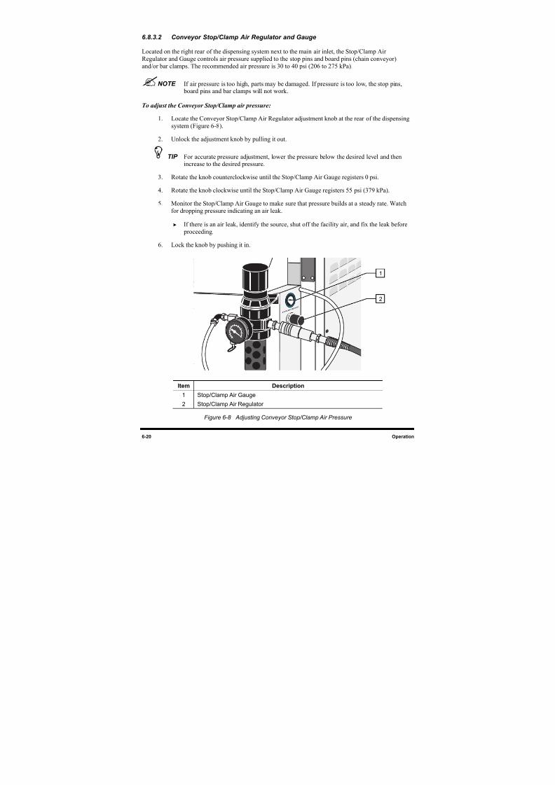
8/16/2019 Dispensig c 740 nordson
http://slidepdf.com/reader/full/dispensig-c-740-nordson 132/240
6-20 Operation
6.8.3.2 Conveyor Stop/Clamp Air Regulator and Gauge
Located on the right rear of the dispensing system next to the main air inlet, the Stop/Clamp Air
Regulator and Gauge controls air pressure supplied to the stop pins and board pins (chain conveyor)
and/or bar clamps. The recommended air pressure is 30 to 40 psi (206 to 275 kPa).
NOTE If air pressure is too high, parts may be damaged. If pressure is too low, the stop pins, board pins and bar clamps will not work.
To adjust the Conveyor Stop/Clamp air pressure:
1. Locate the Conveyor Stop/Clamp Air Regulator adjustment knob at the rear of the dispensing
system (Figure 6-8).
2. Unlock the adjustment knob by pulling it out.
TIP For accurate pressure adjustment, lower the pressure below the desired level and thenincrease to the desired pressure.
3. Rotate the knob counterclockwise until the Stop/Clamp Air Gauge registers 0 psi.
4. Rotate the knob clockwise until the Stop/Clamp Air Gauge registers 55 psi (379 kPa).
5. Monitor the Stop/Clamp Air Gauge to make sure that pressure builds at a steady rate. Watch
for dropping pressure indicating an air leak.
If there is an air leak, identify the source, shut off the facility air, and fix the leak before
proceeding.
6. Lock the knob by pushing it in.
Item Description
1 Stop/Clamp Air Gauge
2 Stop/Clamp Air Regulator
Figure 6-8 Adjusting Conveyor Stop/Clamp Air Pressure
1
2
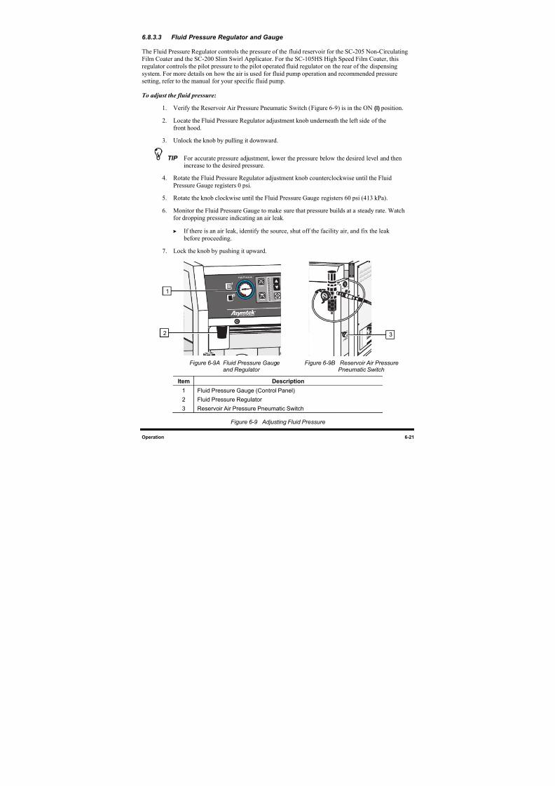
8/16/2019 Dispensig c 740 nordson
http://slidepdf.com/reader/full/dispensig-c-740-nordson 133/240
Operation 6-21
6.8.3.3 Fluid Pressure Regulator and Gauge
The Fluid Pressure Regulator controls the pressure of the fluid reservoir for the SC-205 Non-Circulating
Film Coater and the SC-200 Slim Swirl Applicator. For the SC-105HS High Speed Film Coater, this
regulator controls the pilot pressure to the pilot operated fluid regulator on the rear of the dispensing
system. For more details on how the air is used for fluid pump operation and recommended pressure
setting, refer to the manual for your specific fluid pump.
To adjust the fluid pressure:
1. Verify the Reservoir Air Pressure Pneumatic Switch (Figure 6-9) is in the ON (l) position.
2. Locate the Fluid Pressure Regulator adjustment knob underneath the left side of the
front hood.
3. Unlock the knob by pulling it downward.
TIP For accurate pressure adjustment, lower the pressure below the desired level and thenincrease to the desired pressure.
4. Rotate the Fluid Pressure Regulator adjustment knob counterclockwise until the FluidPressure Gauge registers 0 psi.
5. Rotate the knob clockwise until the Fluid Pressure Gauge registers 60 psi (413 kPa).
6. Monitor the Fluid Pressure Gauge to make sure that pressure builds at a steady rate. Watch
for dropping pressure indicating an air leak.
If there is an air leak, identify the source, shut off the facility air, and fix the leak
before proceeding.
7. Lock the knob by pushing it upward.
Figure 6-9 A Fluid Pressure Gaugeand Regulator
Figure 6-9B Reservoir Air PressurePneumatic Switch
Item Description
1 Fluid Pressure Gauge (Control Panel)
2 Fluid Pressure Regulator
3 Reservoir Air Pressure Pneumatic Switch
Figure 6-9 Adjusting Fluid Pressure
1
2 3
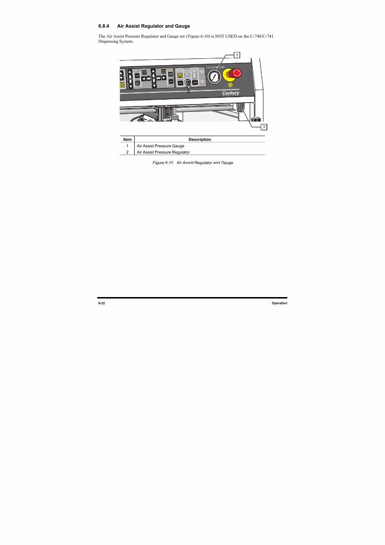
8/16/2019 Dispensig c 740 nordson
http://slidepdf.com/reader/full/dispensig-c-740-nordson 134/240
6-22 Operation
6.8.4 Air Assist Regulator and Gauge
The Air Assist Pressure Regulator and Gauge set (Figure 6-10) is NOT USED on the C-740/C-741
Dispensing System.
Item Description
1 Air Assist Pressure Gauge
2 Air Assist Pressure Regulator
Figure 6-10 Air Assist Regulator and Gauge
1
2
8/16/2019 Dispensig c 740 nordson
http://slidepdf.com/reader/full/dispensig-c-740-nordson 135/240
Operation 6-23
6.9 System Startup/Shutdown
This subsection details basic start-up and shutdown procedures based on different levels of operation. The
following procedures are offered as general recommendations and suggestions when starting and/or
shutting down your Century C-740/C-741 Series Dispensing System. Your actual start-up and shutdown
procedures may vary.
WARNING! Only authorized service technicians or process engineers should connect powercables to the power source. Operators should not attempt to make electricalconnections.
6.9.1 Startup
If necessary, refer to the figures in Section 1 - Introduction to identify system components.
NOTE If you are running a program from a disk, it is recommended that you first run a virus
scan on the disk before downloading anything from the disk to the Computer hard drive.
To start the dispensing system:
1. Verify that the Safety Interlock Keyswitch is in the ON (I) position for production.
2. Close the dispensing system front doors and access covers.
3. Power on the dispensing system as described in 5.3 Powering Up the System.
NOTE Ensure that all items on the Daily Routine Checklist have been completed prior to startingthe production run. Refer to 6.9.3 Daily Routine Procedures.
To Start ECXP:
1. Start ECXP as described in 5.4 Starting Easy Coat for Windows.
2. Refer to 6.10 Conformal Coating Setup Procedures, 6.11 Loading a Program and
6.12 Running a Program for detailed instructions on system setup and running production.
8/16/2019 Dispensig c 740 nordson
http://slidepdf.com/reader/full/dispensig-c-740-nordson 136/240
6-24 Operation
6.9.2 Shutdown
6.9.2.1 Emergency Shutdown
In case of an emergency or malfunction, press the EMO button. The EMO is the large red button on the
Control Panel. Refer to Section 2 -Safety for important information concerning emergency shutdown.
WARNING! Power is still available to the power supply and to the Power Manager after anEmergency Shutdown. To fully remove power to the system, all power cordsmust be disconnected.
6.9.2.2 Routine Shutdown
Routine shutdown may vary depending on your particular requirements. The system may be left in the
power-on state at the end of the day or turned off completely. However, it is recommended that you
incorporate the following procedure into your production shutdown routine:
To shut down at the end of a production shift (overnight):
If you are using a coating material without pot life limitations, follow these steps for shutdown:
1. Wait for the dispensing program to complete.
2. Verify that all motion has stopped.
3. Unload all boards from the conveyor.
4. Turn the reservoir air pressure switch (Figure 6-9B) to the OFF (0) position.
5. Remove the nozzle from the fluid applicator.
6. To prevent material from curing inside the fluid applicator nozzle, immerse the applicator in
the appropriate solvent in the stainless steel solvent cup.
If necessary, use an Asymtek nozzle brush (P/N 901905) to remove build-up.
7. Dry the nozzle and inspect the orifice for blockage.
8. Immerse the nozzle in solvent and store it in a safe place.
9. Exit ECXP.
10. Press the Stop (0) button on the Control Panel.
8/16/2019 Dispensig c 740 nordson
http://slidepdf.com/reader/full/dispensig-c-740-nordson 137/240
Operation 6-25
6.9.2.3 Extended shutdown
If the system will be shut down for several days, or if your coating material has a short pot life, follow the
procedures outlined in the appropriate fluid dispensing applicator manual for cleaning and maintenance of
the fluid applicator and nozzle.
6.9.2.4 Service Shutdown
To shut down for service:
1. Wait for the dispensing program to complete.
2. Verify that all motion has stopped.
3. Press the Stop (0) button on the Control Panel.
4. Unload all boards from the conveyor.
5. Exit ECXP.
6. Exit Windows XP.
7. Turn OFF (0) the main power circuit breaker at the rear of the system.
8. Disconnect the main power cable and lock it in a locked box for safety.
9. Disconnect the facility air supply hose from the main air inlet and place a warning tag on the
main air inlet.
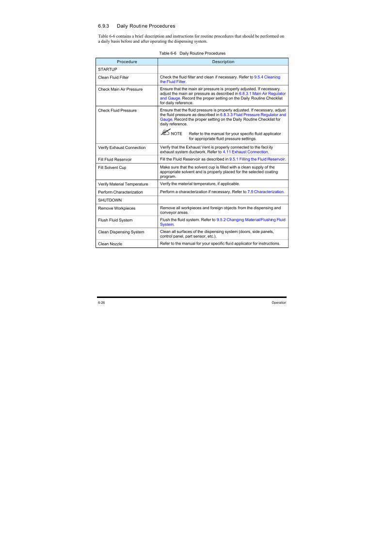
8/16/2019 Dispensig c 740 nordson
http://slidepdf.com/reader/full/dispensig-c-740-nordson 138/240
6-26 Operation
6.9.3 Daily Routine Procedures
Table 6-6 contains a brief description and instructions for routine procedures that should be performed on
a daily basis before and after operating the dispensing system.
Table 6-6 Daily Routine Procedures
Procedure Description
STARTUP
Clean Fluid Filter Check the fluid filter and clean if necessary. Refer to 9.5.4 Cleaning the Fluid Filter .
Check Main Air Pressure Ensure that the main air pressure is properly adjusted. If necessary,adjust the main air pressure as described in 6.8.3.1 Main Air Regulatorand Gauge. Record the proper setting on the Daily Routine Checklistfor daily reference.
Check Fluid Pressure Ensure that the fluid pressure is properly adjusted. If necessary, adjustthe fluid pressure as described in 6.8.3.3 Fluid Pressure Regulator andGauge. Record the proper setting on the Daily Routine Checklist for
daily reference.
NOTE Refer to the manual for your specific fluid applicator
for appropriate fluid pressure settings.
Verify Exhaust Connection Verify that the Exhaust Vent is properly connected to the facilityexhaust system ductwork. Refer to 4.11 Exhaust Connection.
Fill Fluid Reservoir Fill the Fluid Reservoir as described in 9.5.1 Filling the Fluid Reservoir .
Fill Solvent Cup Make sure that the solvent cup is filled with a clean supply of theappropriate solvent and is properly placed for the selected coatingprogram.
Verify Material Temperature Verify the material temperature, if applicable.
Perform Characterization Perform a characterization if necessary. Refer to 7.5 Characterization.
SHUTDOWN
Remove Workpieces Remove all workpieces and foreign objects from the dispensing andconveyor areas.
Flush Fluid System Flush the fluid system. Refer to 9.5.2 Changing Material/Flushing Fluid System.
Clean Dispensing System Clean all surfaces of the dispensing system (doors, side panels,control panel, part sensor, etc.).
Clean NozzleRefer to the manual for your specific fluid applicator for instructions.
8/16/2019 Dispensig c 740 nordson
http://slidepdf.com/reader/full/dispensig-c-740-nordson 139/240
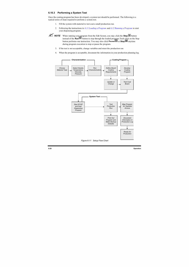
8/16/2019 Dispensig c 740 nordson
http://slidepdf.com/reader/full/dispensig-c-740-nordson 140/240
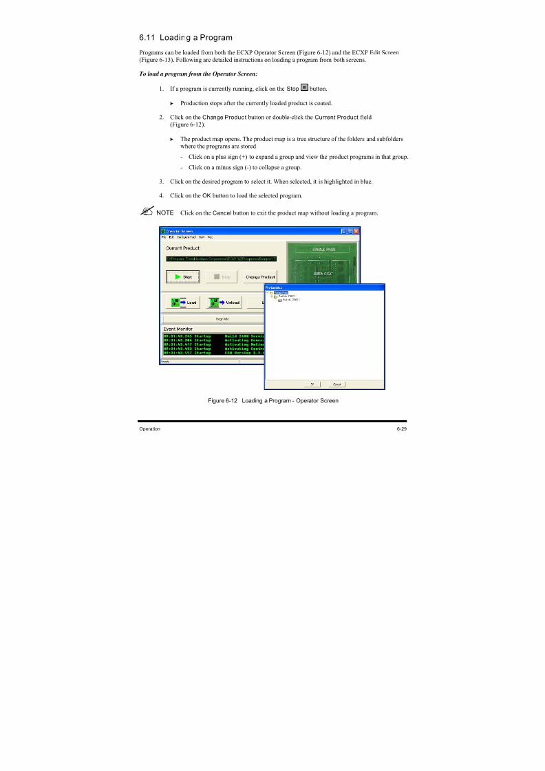
8/16/2019 Dispensig c 740 nordson
http://slidepdf.com/reader/full/dispensig-c-740-nordson 141/240
Operation 6-29
6.11 Loading a Program
Programs can be loaded from both the ECXP Operator Screen (Figure 6-12) and the ECXP Edit Screen
(Figure 6-13). Following are detailed instructions on loading a program from both screens.
To load a program from the Operator Screen:
1.
If a program is currently running, click on the Stop
button.
Production stops after the currently loaded product is coated.
2.
Click on the Change Product button or double-click the Current Product field
(Figure 6-12).
The product map opens. The product map is a tree structure of the folders and subfolders
where the programs are stored.
- Click on a plus sign (+) to expand a group and view the product programs in that group.
-
Click on a minus sign (-) to collapse a group.
3. Click on the desired program to select it. When selected, it is highlighted in blue.
4. Click on the OK button to load the selected program.
NOTE Click on the Cancel button to exit the product map without loading a program.
Figure 6-12 Loading a Program - Operator Screen
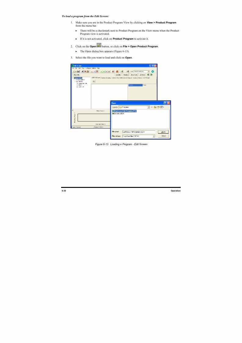
8/16/2019 Dispensig c 740 nordson
http://slidepdf.com/reader/full/dispensig-c-740-nordson 142/240
6-30 Operation
To load a program from the Edit Screen:
1. Make sure you are in the Product Program View by clicking on View > Product Program
from the menu bar.
There will be a checkmark next to Product Program on the View menu when the Product
Program view is activated.
If it is not activated, click on Product Program to activate it.
2. Click on the Open button, or click on File > Open Product Program.
The Open
dialog box appears (Figure 6-13).
3. Select the file you want to load and click on Open.
Figure 6-13 Loading a Program - Edit Screen
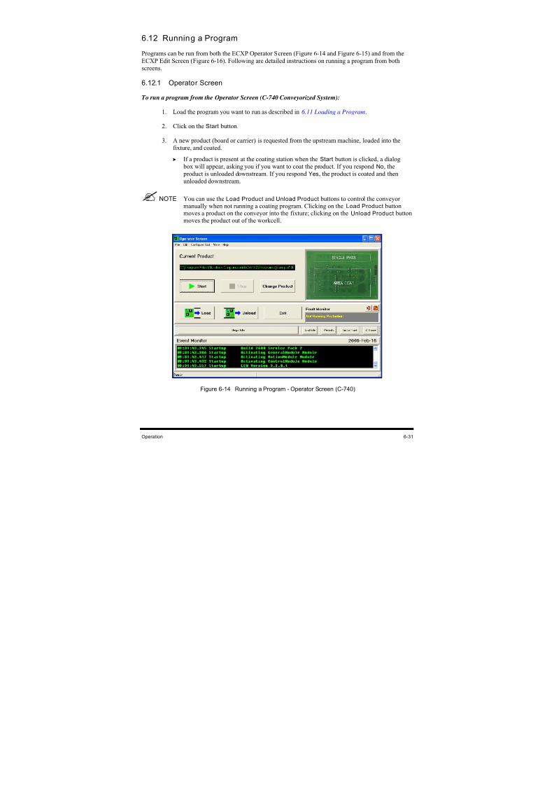
8/16/2019 Dispensig c 740 nordson
http://slidepdf.com/reader/full/dispensig-c-740-nordson 143/240
Operation 6-31
6.12 Running a Program
Programs can be run from both the ECXP Operator Screen (Figure 6-14 and Figure 6-15) and from the
ECXP Edit Screen (Figure 6-16). Following are detailed instructions on running a program from both
screens.
6.12.1 Operator Screen
To run a program from the Operator Screen (C-740 Conveyorized System):
1. Load the program you want to run as described in 6.11 Loading a Program.
2. Click on the Start button.
3. A new product (board or carrier) is requested from the upstream machine, loaded into the
fixture, and coated.
If a product is present at the coating station when the Start button is clicked, a dialog
box will appear, asking you if you want to coat the product. If you respond No, the
product is unloaded downstream. If you respond Yes, the product is coated and then
unloaded downstream.
NOTE You can use the Load Product and Unload Product buttons to control the conveyormanually when not running a coating program. Clicking on the Load Product buttonmoves a product on the conveyor into the fixture; clicking on the Unload Product buttonmoves the product out of the workcell.
Figure 6-14 Running a Program - Operator Screen (C-740)
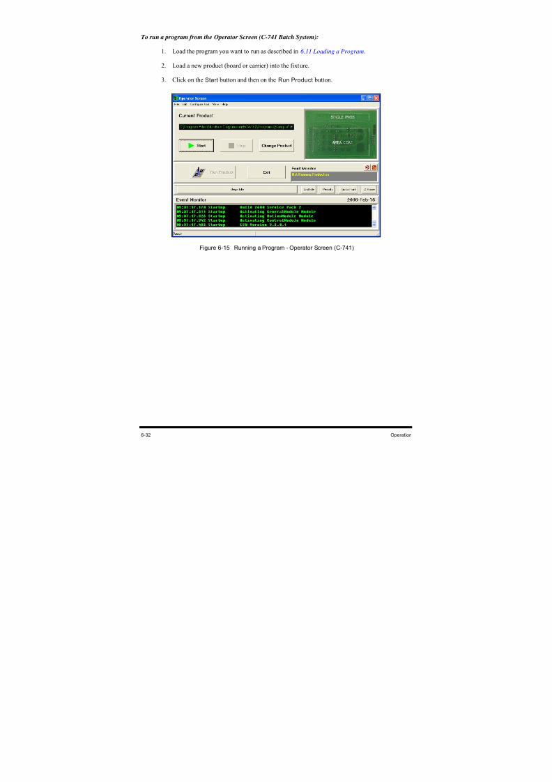
8/16/2019 Dispensig c 740 nordson
http://slidepdf.com/reader/full/dispensig-c-740-nordson 144/240
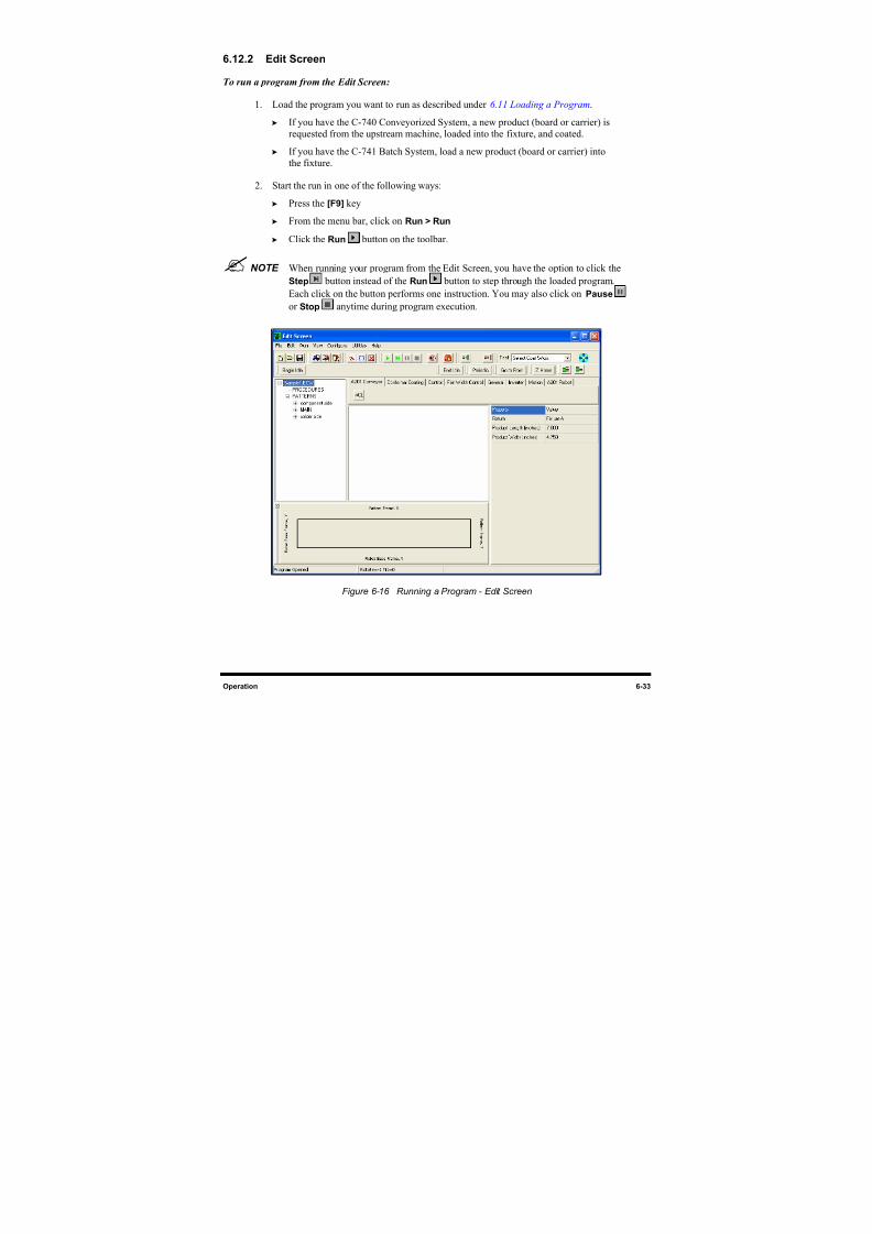
8/16/2019 Dispensig c 740 nordson
http://slidepdf.com/reader/full/dispensig-c-740-nordson 145/240
Operation 6-33
6.12.2 Edit Screen
To run a program from the Edit Screen:
1. Load the program you want to run as described under 6.11 Loading a Program.
If you have the C-740 Conveyorized System, a new product (board or carrier) is
requested from the upstream machine, loaded into the fixture, and coated.
If you have the C-741 Batch System, load a new product (board or carrier) into
the fixture.
2. Start the run in one of the following ways:
Press the [F9] key
From the menu bar, click on Run > Run
Click the Run button on the toolbar.
NOTE When running your program from the Edit Screen, you have the option to click the
Step button instead of the Run button to step through the loaded program.Each click on the button performs one instruction. You may also click on Pause
or Stop anytime during program execution.
Figure 6-16 Running a Program - Edit Screen
8/16/2019 Dispensig c 740 nordson
http://slidepdf.com/reader/full/dispensig-c-740-nordson 146/240
6-34 Operation
6.13 Production Statistics
6.13.1 Database Utility
The ECXP Database Utility lets you export production data to ASCII text tables. The tables can then be
imported into database or spreadsheet programs for further analysis. By default, ten days of data are
stored in the database.
NOTE Old data is purged when ECXP starts. If the database files become very large, databasemaintenance can delay ECXP startup.
The following tables may be exported:
• Fan Width Control: Pressure and Width
• Flowmeter: Volumes dispensed.
• Production: Cycle Times
To export production data:
1. Click on Utilities > Database > Export Table in ASCII format.
2. Click on the desired table in the lower window of the dialog box.
To select more than one table, hold down the [Shift] key while clicking on the
additional tables.
3. Click on OK.
The Save As dialog box appears.
4. Select a destination for the table to be exported and give it a unique filename.
5. Click on OK to export the table.
If you selected more than one table, the Save As dialog box will reappear after the first
table has been saved. You will be prompted to select a destination and enter a filename
for the next table.
8/16/2019 Dispensig c 740 nordson
http://slidepdf.com/reader/full/dispensig-c-740-nordson 147/240
Configuration and Characterization 7-1
7 Configuration and Characterization
7.1 Overview
Your dispensing system is configured at the Asymtek factory prior to shipping. However, if any
components have been changed or moved, it may be necessary to reconfigure them. This section contains
the following procedures:
• Tool Configuration • Inverter Configuration
• Characterization • Robot Configuration
• Fan Width Configuration • Bar Code Scanner Configuration
• Fixture Configuration • Reconfigure
• Conveyor Configuration
7.2 Safety FirstBefore configuring any of the dispensing system components, please review the information presented in
Section 2 - Safety.
CAUTION! The procedures in this section should only be performed by a trained servicetechnician.
7.3 Record Keeping
At a minimum, the following information should be recorded in the dispensing system maintenance
records:
• Procedure Type
• Date
• Technician Name(s)
• Post-procedure Functional Test Results
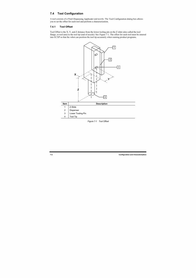
8/16/2019 Dispensig c 740 nordson
http://slidepdf.com/reader/full/dispensig-c-740-nordson 148/240
7-2 Configuration and Characterization
7.4 Tool Configuration
A tool consists of a Fluid Dispensing Applicator and nozzle. The Tool Configuration dialog box allows
you to set the offset for each tool and perform a characterization.
7.4.1 Tool Offset
Tool Offset is the X, Y, and Z distance from the lower tooling pin on the Z slide (also called the toolflange, or tool arm) to the tool tip (end of nozzle). See Figure 7-1. The offset for each tool must be entered
into ECXP so that the robot can position the tool tip accurately when running product programs.
Item Description
1 Z-Slide
2 Dispenser
3 Lower Tooling Pin
4 Tool Tip
Figure 7-1 Tool Offset
1
2
3
4
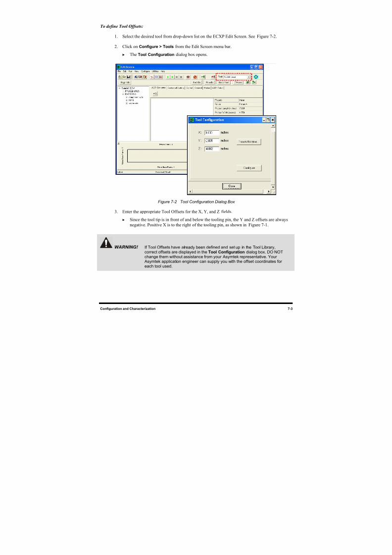
8/16/2019 Dispensig c 740 nordson
http://slidepdf.com/reader/full/dispensig-c-740-nordson 149/240
Configuration and Characterization 7-3
To define Tool Offsets:
1. Select the desired tool from drop-down list on the ECXP Edit Screen. See Figure 7-2.
2. Click on Configure > Tools from the Edit Screen menu bar.
The Tool Configuration
dialog box opens.
Figure 7-2 Tool Configuration Dialog Box
3. Enter the appropriate Tool Offsets for the X, Y, and Z
fields.
Since the tool tip is in front of and below the tooling pin, the Y and Z offsets are always
negative. Positive X is to the right of the tooling pin, as shown in Figure 7-1.
WARNING! If Tool Offsets have already been defined and set up in the Tool Library,
correct offsets are displayed in the Tool Configuration dialog box. DO NOTchange them without assistance from your Asymtek representative. Your
Asymtek application engineer can supply you with the offset coordinates foreach tool used.
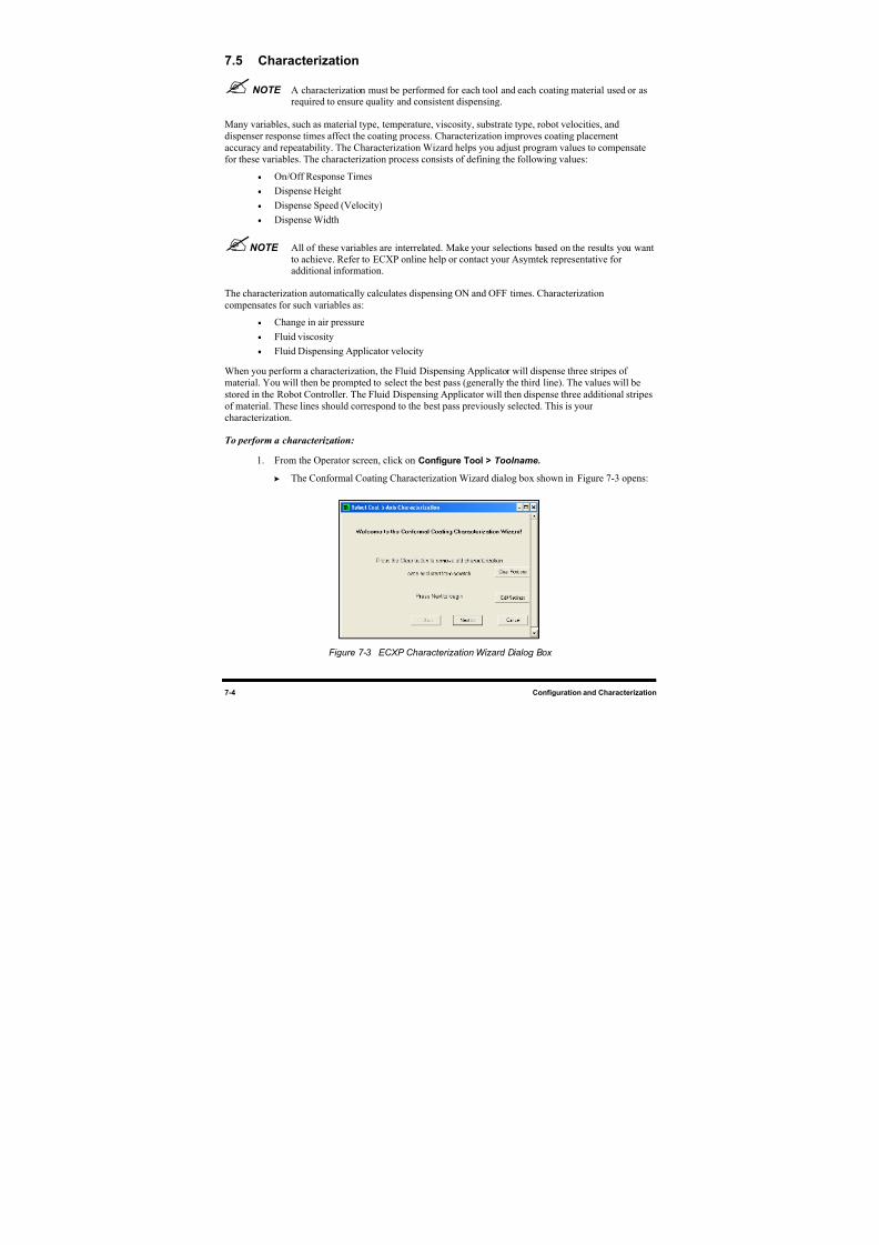
8/16/2019 Dispensig c 740 nordson
http://slidepdf.com/reader/full/dispensig-c-740-nordson 150/240
7-4 Configuration and Characterization
7.5 Characterization
NOTE A characterization must be performed for each tool and each coating material used or asrequired to ensure quality and consistent dispensing.
Many variables, such as material type, temperature, viscosity, substrate type, robot velocities, and
dispenser response times affect the coating process. Characterization improves coating placementaccuracy and repeatability. The Characterization Wizard helps you adjust program values to compensate
for these variables. The characterization process consists of defining the following values:
• On/Off Response Times
• Dispense Height
• Dispense Speed (Velocity)
• Dispense Width
NOTE All of these variables are interrelated. Make your selections based on the results you wantto achieve. Refer to ECXP online help or contact your Asymtek representative foradditional information.
The characterization automatically calculates dispensing ON and OFF times. Characterization
compensates for such variables as:
• Change in air pressure
• Fluid viscosity
• Fluid Dispensing Applicator velocity
When you perform a characterization, the Fluid Dispensing Applicator will dispense three stripes of
material. You will then be prompted to select the best pass (generally the third line). The values will be
stored in the Robot Controller. The Fluid Dispensing Applicator will then dispense three additional stripes
of material. These lines should correspond to the best pass previously selected. This is your
characterization.
To perform a characterization:
1. From the Operator screen, click on Configure Tool > Toolname.
The Conformal Coating Characterization Wizard dialog box shown in Figure 7-3 opens:
Figure 7-3 ECXP Characterization Wizard Dialog Box
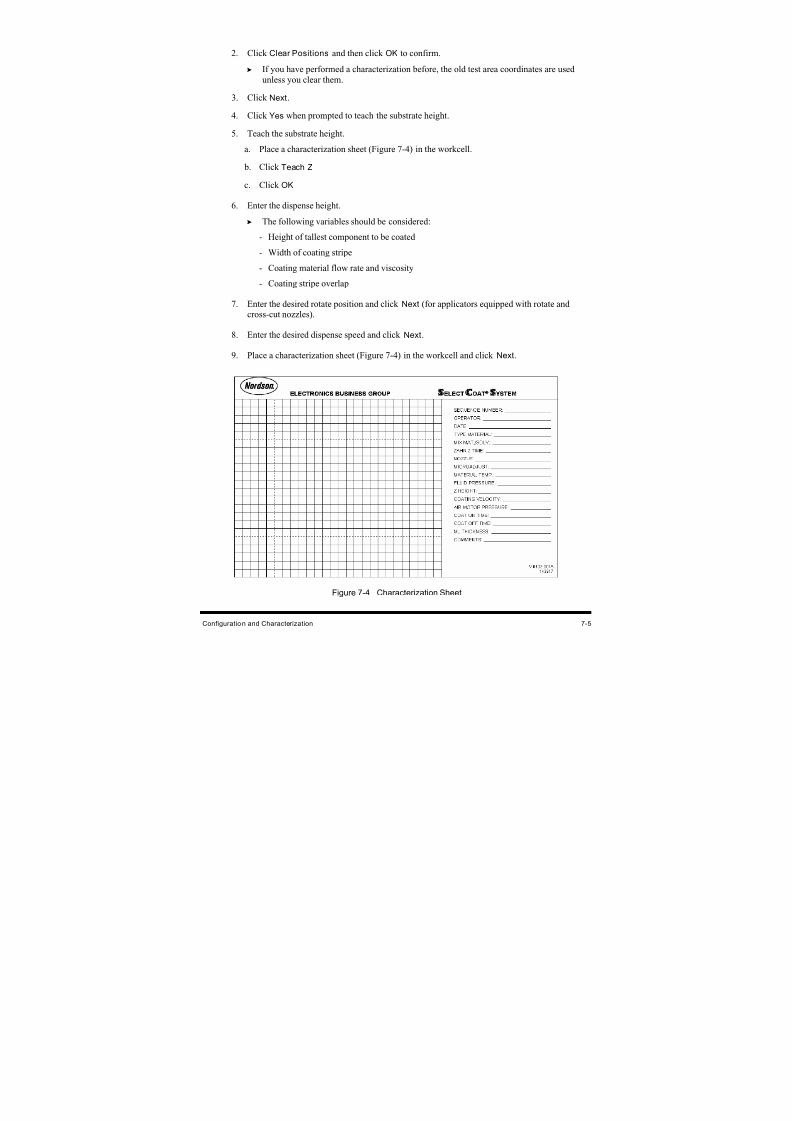
8/16/2019 Dispensig c 740 nordson
http://slidepdf.com/reader/full/dispensig-c-740-nordson 151/240
Configuration and Characterization 7-5
2. Click Clear Positions and then click OK to confirm.
If you have performed a characterization before, the old test area coordinates are used
unless you clear them.
3.
Click Next.
4.
Click Yes when prompted to teach the substrate height.
5. Teach the substrate height.
a. Place a characterization sheet (Figure 7-4) in the workcell.
b.
Click Teach Z
c. Click OK
6. Enter the dispense height.
The following variables should be considered:
-
Height of tallest component to be coated
-
Width of coating stripe
- Coating material flow rate and viscosity
- Coating stripe overlap
7. Enter the desired rotate position and click Next (for applicators equipped with rotate andcross-cut nozzles).
8. Enter the desired dispense speed and click Next.
9. Place a characterization sheet (Figure 7-4) in the workcell and click Next.
Figure 7-4 Characterization Sheet
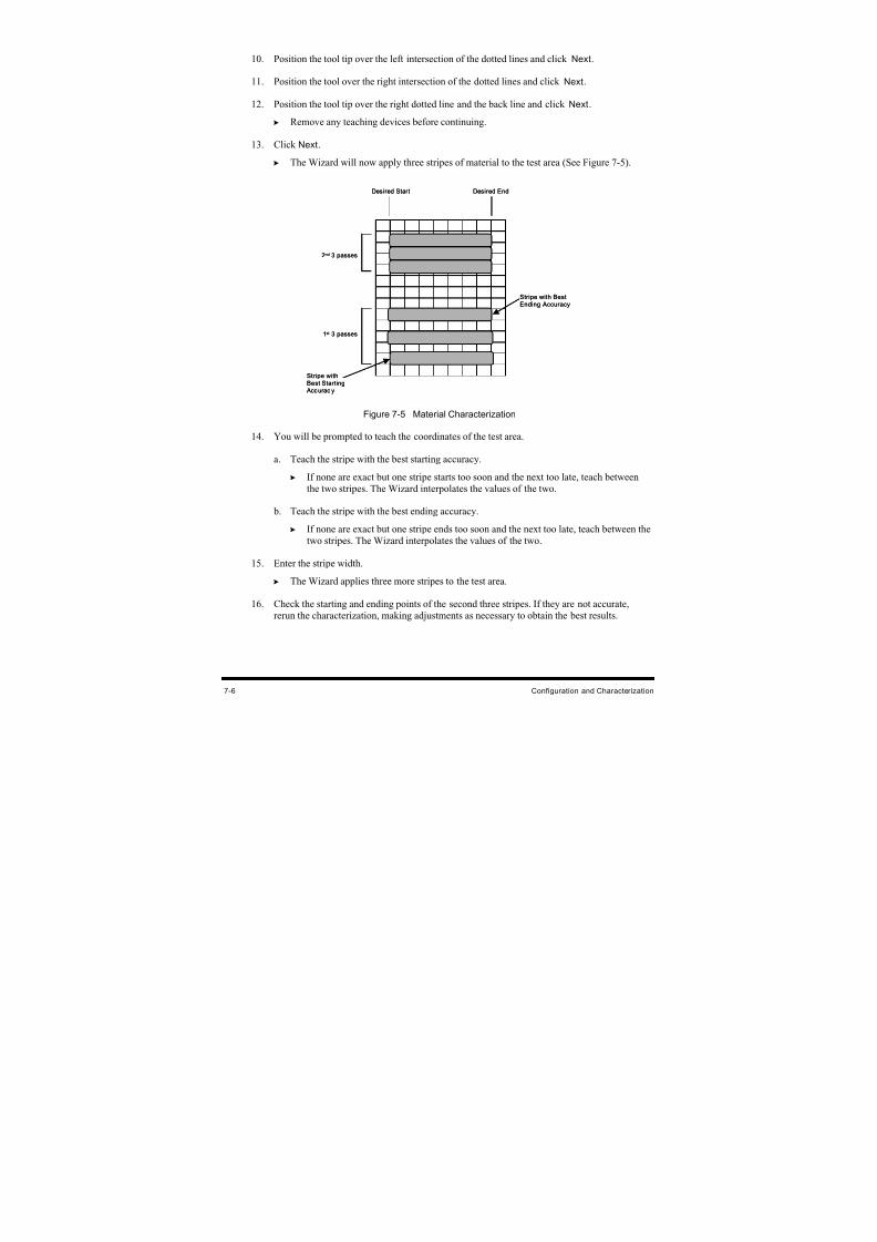
8/16/2019 Dispensig c 740 nordson
http://slidepdf.com/reader/full/dispensig-c-740-nordson 152/240
8/16/2019 Dispensig c 740 nordson
http://slidepdf.com/reader/full/dispensig-c-740-nordson 153/240
Configuration and Characterization 7-7
17. The settings will be displayed for your approval. The only variable you can change is the
stripe width. To change any other settings, you will have to rerun the characterization.
TIP To perform a characterization from the ECXP Edit screen, click on Configure > Tools.
The Tool Configuration dialog box opens. Select the tab for the tool you wish
characterize, then click the Configure button.
7.6 Fan Width Configuration
If your system is equipped with the optional Laser Fan Width Control feature, you will need to perform a
Fan Width Setup. For additional information, refer to the manual for your Laser Fan Width Control
System or contact your Asymtek representative.
7.6.1 Fan Width Setup
Before configuring the fluid fan width, you must perform a tool configuration and characterization. Refer
to 7.4 Tool Configuration and 7.5 Characterization for detailed instructions.
NOTE Fan Width Control is available only for the Select Coat Tool. For more information,contact your Asymtek representative.
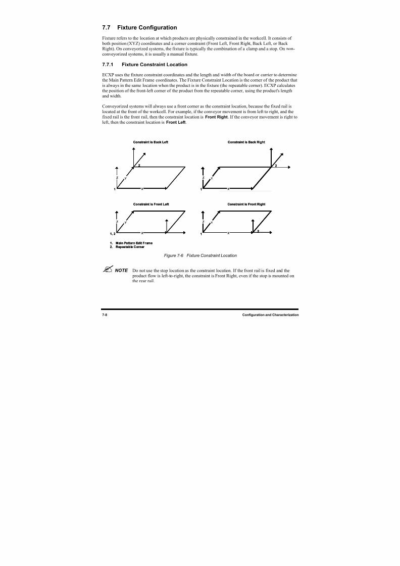
8/16/2019 Dispensig c 740 nordson
http://slidepdf.com/reader/full/dispensig-c-740-nordson 154/240
7-8 Configuration and Characterization
7.7 Fixture Configuration
Fixture refers to the location at which products are physically constrained in the workcell. It consists of
both position (XYZ) coordinates and a corner constraint (Front Left, Front Right, Back Left, or Back
Right). On conveyorized systems, the fixture is typically the combination of a clamp and a stop. On non-
conveyorized systems, it is usually a manual fixture.
7.7.1 Fixture Constraint Location
ECXP uses the fixture constraint coordinates and the length and width of the board or carrier to determinethe Main Pattern Edit Frame coordinates. The Fixture Constraint Location is the corner of the product that
is always in the same location when the product is in the fixture (the repeatable corner). ECXP calculates
the position of the front-left corner of the product from the repeatable corner, using the product's length
and width.
Conveyorized systems will always use a front corner as the constraint location, because the fixed rail is
located at the front of the workcell. For example, if the conveyor movement is from left to right, and the
fixed rail is the front rail, then the constraint location is Front Right. If the conveyor movement is right to
left, then the constraint location is Front Left.
X
YZ
X
YZ
X
YZ
X
YZ
Constraint is Front Left Constraint is Front Right
Constraint is Back Left Constraint is Back Right
2
1 1
2
1, 2 12
1. Main Pattern Edit Frame
2. Repeatable Corner
X
YZ
X
YZ
X
YZ
X
YZ
X
YZ
X
YZ
X
YZ
X
YZ
X
YZ
X
YZ
X
YZ
X
YZ
Constraint is Front Left Constraint is Front Right
Constraint is Back Left Constraint is Back Right
2
1 1
2
1, 2 12
1. Main Pattern Edit Frame
2. Repeatable Corner
Figure 7-6 Fixture Constraint Location
NOTE Do not use the stop location as the constraint location. If the front rail is fixed and the product flow is left-to-right, the constraint is Front Right, even if the stop is mounted onthe rear rail.
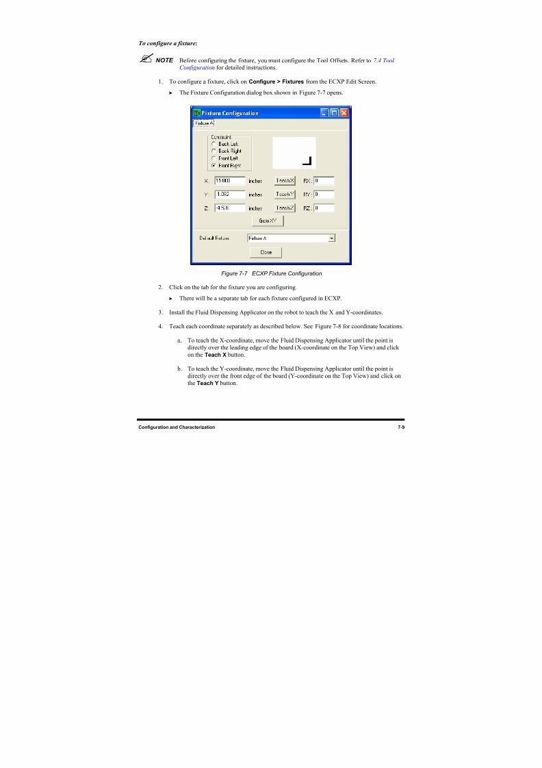
8/16/2019 Dispensig c 740 nordson
http://slidepdf.com/reader/full/dispensig-c-740-nordson 155/240
Configuration and Characterization 7-9
To configure a fixture:
NOTE Before configuring the fixture, you must configure the Tool Offsets. Refer to 7.4 ToolConfiguration for detailed instructions.
1. To configure a fixture, click on Configure > Fixtures from the ECXP Edit Screen.
The Fixture Configuration dialog box shown in Figure 7-7 opens.
Figure 7-7 ECXP Fixture Configuration
2. Click on the tab for the fixture you are configuring.
There will be a separate tab for each fixture configured in ECXP.
3. Install the Fluid Dispensing Applicator on the robot to teach the X and Y-coordinates.
4. Teach each coordinate separately as described below. See Figure 7-8 for coordinate locations.
a. To teach the X-coordinate, move the Fluid Dispensing Applicator until the point is
directly over the leading edge of the board (X-coordinate on the Top View) and clickon the Teach X button.
b. To teach the Y-coordinate, move the Fluid Dispensing Applicator until the point is
directly over the front edge of the board (Y-coordinate on the Top View) and click on
the Teach Y button.
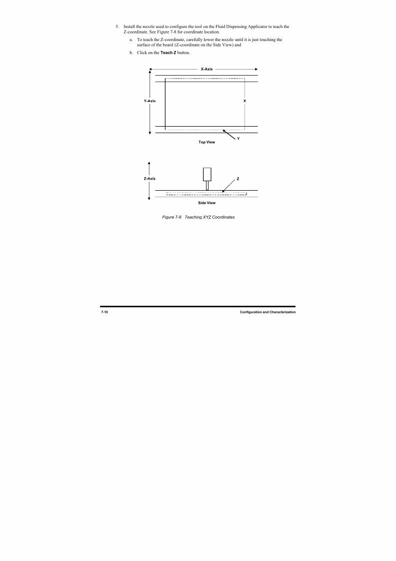
8/16/2019 Dispensig c 740 nordson
http://slidepdf.com/reader/full/dispensig-c-740-nordson 156/240
7-10 Configuration and Characterization
5. Install the nozzle used to configure the tool on the Fluid Dispensing Applicator to teach the
Z-coordinate. See Figure 7-8 for coordinate location.
a. To teach the Z-coordinate, carefully lower the nozzle until it is just touching the
surface of the board (Z-coordinate on the Side View) and
b. Click on the Teach Z button.
Figure 7-8 Teaching XYZ Coordinates
X-Axis
Y-Axis
Z
Side View
YTop View
X
Z-Axis
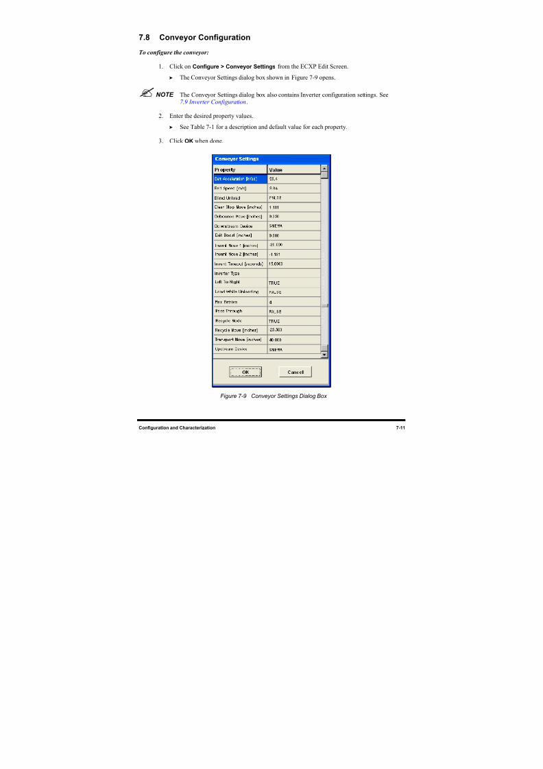
8/16/2019 Dispensig c 740 nordson
http://slidepdf.com/reader/full/dispensig-c-740-nordson 157/240
Configuration and Characterization 7-11
7.8 Conveyor Configuration
To configure the conveyor:
1. Click on Configure > Conveyor Settings from the ECXP Edit Screen.
The Conveyor Settings dialog box shown in Figure 7-9 opens.
NOTE The Conveyor Settings dialog box also contains Inverter configuration settings. See7.9 Inverter Configuration.
2. Enter the desired property values.
See Table 7-1 for a description and default value for each property.
3. Click OK when done.
Figure 7-9 Conveyor Settings Dialog Box
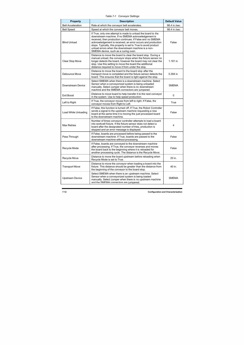
8/16/2019 Dispensig c 740 nordson
http://slidepdf.com/reader/full/dispensig-c-740-nordson 158/240
7-12 Configuration and Characterization
Table 7-1 Conveyor Settings
Property Description Default Value
Belt Acceleration Rate at which the conveyor belt accelerates. 98.4 in./sec
Belt Speed Speed at which the conveyor belt moves. 98.4 in./sec
Blind Unload
If True, only one attempt is made to unload the board to thedownstream machine. If no SMEMA acknowledgement is
received, then production continues. If False and no SMEMAacknowledgement is received, an error occurs and productionstops. Typically, this property is set to True to avoid productunload errors when the downstream machine is a non-SMEMA device, such as a curing oven.
False
Clear Stop Move
Distance to move the board to clear the board stop. During amanual unload, the conveyor stops when the fixture sensor nolonger detects the board, however the board may not clear thestop. Use this setting to move the board the additionaldistance required to move it from under the stop.
1.181 in.
Debounce MoveDistance to move the board to the board stop after thetransport move is completed and the fixture sensor detects the
board. This ensures that the board is tight against the stop.
0.394 in.
Downstream Device
Select SMEMA when there is a downstream machine. SelectSensor when a conveyorized system is being unloadedmanually. Select Jumper when there is no downstreammachine and the SMEMA connectors are jumpered.
SMEMA
Exit BoostDistance to move board to help transfer it to the next conveyorin the system. Use to help speed production.
0
Left to RightIf True, the conveyor moves from left to right. If False, theconveyor moves from Right to Left.
True
Load While Unloading
If False, this function is turned off. If True, the Robot Controllersends a signal to the upstream machine requesting a newboard at the same time it is moving the just-processed board
to the downstream machine.
False
Max Retries
Number of times conveyor controller attempts to load a boardinto workcell fixture. If the fixture sensor does not detect aboard after the designated number of tries, production isstopped and an error message is displayed.
4
Pass ThroughIf False, boards are processed before being passed to thedownstream machine. If True, boards are passed to thedownstream machine without processing.
False
Recycle Mode
If False, boards are conveyed to the downstream machineafter processing. If True, the conveyor reverses and movesthe board back to the beginning where it is reloaded foranother processing cycle. The distance is the Recycle Move.
False
Recycle Move Distance to move the board upstream before reloading whenRecycle Mode is set to True.
20 in.
Transport MoveDistance to move the conveyor when loading a board into thefixture. This distance should be greater than the distance fromthe beginning of the conveyor to the board stop.
40 in.
Upstream Device
Select SMEMA when there is an upstream machine. SelectSensor when a conveyorized system is being loadedmanually. Select Jumper when there is no upstream machineand the SMEMA connectors are jumpered.
SMEMA
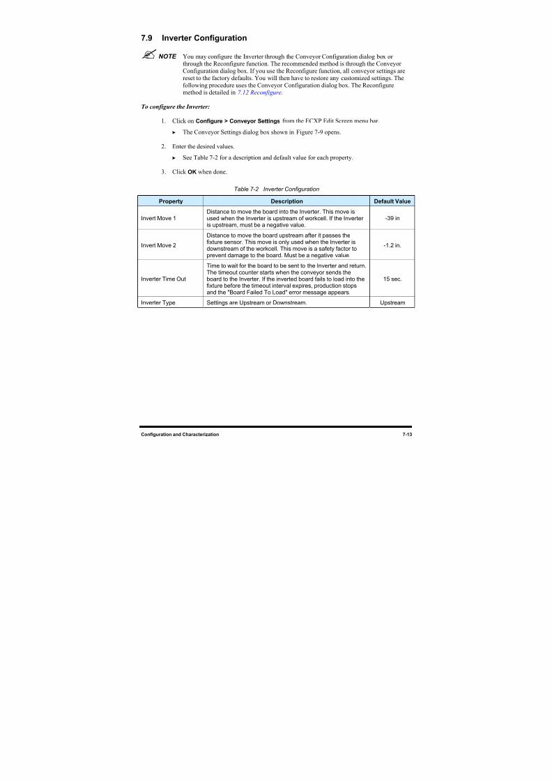
8/16/2019 Dispensig c 740 nordson
http://slidepdf.com/reader/full/dispensig-c-740-nordson 159/240
Configuration and Characterization 7-13
7.9 Inverter Configuration
NOTE You may configure the Inverter through the Conveyor Configuration dialog box orthrough the Reconfigure function. The recommended method is through the ConveyorConfiguration dialog box. If you use the Reconfigure function, all conveyor settings arereset to the factory defaults. You will then have to restore any customized settings. The
following procedure uses the Conveyor Configuration dialog box. The Reconfiguremethod is detailed in 7.12 Reconfigure.
To configure the Inverter:
1. Click on Configure > Conveyor Settings from the ECXP Edit Screen menu bar.
The Conveyor Settings dialog box shown in Figure 7-9 opens.
2. Enter the desired values.
See Table 7-2 for a description and default value for each property.
3. Click OK when done.
Table 7-2 Inverter Configuration
Property Description Default Value
Invert Move 1Distance to move the board into the Inverter. This move isused when the Inverter is upstream of workcell. If the Inverteris upstream, must be a negative value.
-39 in
Invert Move 2
Distance to move the board upstream after it passes thefixture sensor. This move is only used when the Inverter isdownstream of the workcell. This move is a safety factor toprevent damage to the board. Must be a negative value.
-1.2 in.
Inverter Time Out
Time to wait for the board to be sent to the Inverter and return.The timeout counter starts when the conveyor sends theboard to the Inverter. If the inverted board fails to load into thefixture before the timeout interval expires, production stopsand the "Board Failed To Load" error message appears.
15 sec.
Inverter Type Settings are Upstream or Downstream. Upstream
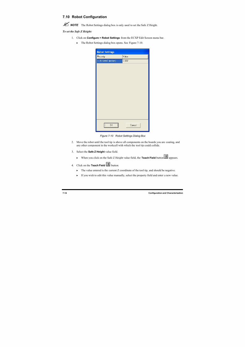
8/16/2019 Dispensig c 740 nordson
http://slidepdf.com/reader/full/dispensig-c-740-nordson 160/240
7-14 Configuration and Characterization
7.10 Robot Configuration
NOTE The Robot Settings dialog box is only used to set the Safe Z Height.
To set the Safe Z Height:
1. Click on Configure > Robot Settings from the ECXP Edit Screen menu bar. The Robot Settings dialog box opens. See Figure 7-10.
Figure 7-10 Robot Settings Dialog Box
2. Move the robot until the tool tip is above all components on the boards you are coating, and
any other component in the workcell with which the tool tip could collide.
3. Select the Safe Z Height value field.
When you click on the Safe Z Height value field, the Teach Field button appears.
4. Click on the Teach Field button.
The value entered is the current Z coordinate of the tool tip, and should be negative.
If you wish to edit this value manually, select the property field and enter a new value.
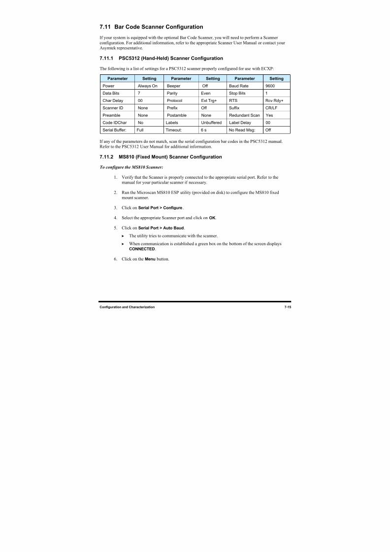
8/16/2019 Dispensig c 740 nordson
http://slidepdf.com/reader/full/dispensig-c-740-nordson 161/240
Configuration and Characterization 7-15
7.11 Bar Code Scanner Configuration
If your system is equipped with the optional Bar Code Scanner, you will need to perform a Scanner
configuration. For additional information, refer to the appropriate Scanner User Manual or contact your
Asymtek representative.
7.11.1 PSC5312 (Hand-Held) Scanner Configuration
The following is a list of settings for a PSC5312 scanner properly configured for use with ECXP:
Parameter Setting Parameter Setting Parameter Setting
Power Always On Beeper Off Baud Rate 9600
Data Bits 7 Parity Even Stop Bits 1
Char Delay 00 Protocol Ext Trg+ RTS Rcv Rdy+
Scanner ID None Prefix Off Suffix CR/LF
Preamble None Postamble None Redundant Scan Yes
Code IDChar No Labels Unbuffered Label Delay 00Serial Buffer: Full Timeout: 6 s No Read Msg: Off
If any of the parameters do not match, scan the serial configuration bar codes in the PSC5312 manual.
Refer to the PSC5312 User Manual for additional information.
7.11.2 MS810 (Fixed Mount) Scanner Configuration
To configure the MS810 Scanner:
1. Verify that the Scanner is properly connected to the appropriate serial port. Refer to the
manual for your particular scanner if necessary.
2. Run the Microscan MS810 ESP utility (provided on disk) to configure the MS810 fixed
mount scanner.
3. Click on Serial Port > Configure.
4. Select the appropriate Scanner port and click on OK.
5. Click on Serial Port > Auto Baud.
The utility tries to communicate with the scanner.
When communication is established a green box on the bottom of the screen displays
CONNECTED.
6. Click on the Menu button.
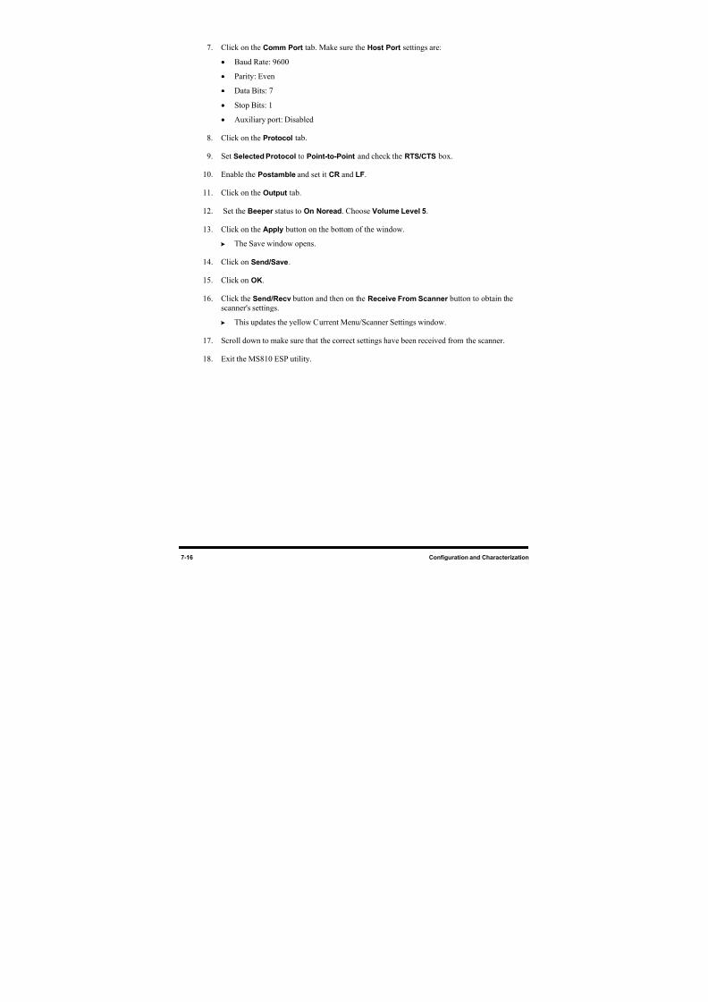
8/16/2019 Dispensig c 740 nordson
http://slidepdf.com/reader/full/dispensig-c-740-nordson 162/240
7-16 Configuration and Characterization
7. Click on the Comm Port tab. Make sure the Host Port settings are:
• Baud Rate: 9600
• Parity: Even
• Data Bits: 7
• Stop Bits: 1
• Auxiliary port: Disabled
8. Click on the Protocol tab.
9. Set Selected Protocol to Point-to-Point and check the RTS/CTS
box.
10. Enable the Postamble and set it CR and LF.
11. Click on the Output tab.
12. Set the Beeper status to On Noread. Choose Volume Level 5.
13. Click on the Apply
button on the bottom of the window.
The Save window opens.
14. Click on Send/Save.
15. Click on OK.
16. Click the Send/Recv
button and then on the Receive From Scanner button to obtain the
scanner's settings.
This updates the yellow Current Menu/Scanner Settings window.
17. Scroll down to make sure that the correct settings have been received from the scanner.
18. Exit the MS810 ESP utility.
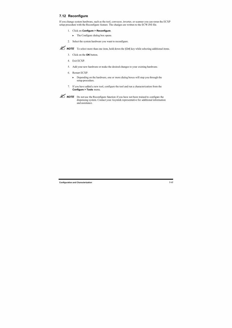
8/16/2019 Dispensig c 740 nordson
http://slidepdf.com/reader/full/dispensig-c-740-nordson 163/240
Configuration and Characterization 7-17
7.12 Reconfigure
If you change system hardware, such as the tool, conveyor, inverter, or scanner you can rerun the ECXP
setup procedure with the Reconfigure feature. The changes are written to the ECW.INI file.
1. Click on Configure > Reconfigure.
The Configure dialog box opens.
2. Select the system hardware you want to reconfigure.
NOTE To select more than one item, hold down the [Ctrl] key while selecting additional items.
3. Click on the OK
button.
4. Exit ECXP.
5. Add your new hardware or make the desired changes to your existing hardware.
6. Restart ECXP.
Depending on the hardware, one or more dialog boxes will step you through the
setup procedure.
7. If you have added a new tool, configure the tool and run a characterization from the
Configure > Tools menu.
NOTE Do not use the Reconfigure function if you have not been trained to configure thedispensing system. Contact your Asymtek representative for additional informationand assistance.

8/16/2019 Dispensig c 740 nordson
http://slidepdf.com/reader/full/dispensig-c-740-nordson 164/240
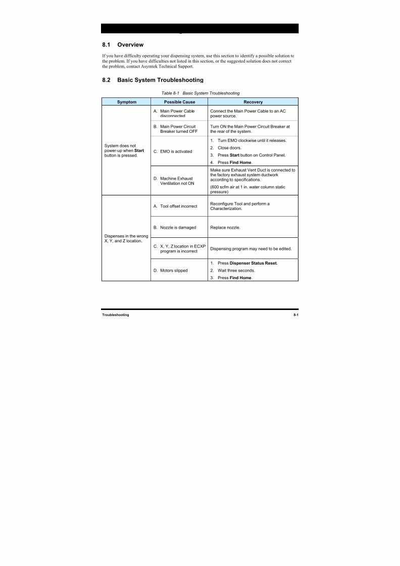
8/16/2019 Dispensig c 740 nordson
http://slidepdf.com/reader/full/dispensig-c-740-nordson 165/240
Troubleshooting 8-1
8 Troubleshooting
8.1 Overview
If you have difficulty operating your dispensing system, use this section to identify a possible solution to
the problem. If you have difficulties not listed in this section, or the suggested solution does not correct
the problem, contact Asymtek Technical Support.
8.2 Basic System Troubleshooting
Table 8-1 Basic System Troubleshooting
Symptom Possible Cause Recovery
A. Main Power Cabledisconnected
Connect the Main Power Cable to an ACpower source.
B. Main Power CircuitBreaker turned OFF Turn ON the Main Power Circuit Breaker atthe rear of the system.
C. EMO is activated
1. Turn EMO clockwise until it releases.
2. Close doors.
3. Press Start button on Control Panel.
4. Press Find Home.
System does notpower-up when Start button is pressed.
D. Machine ExhaustVentilation not ON
Make sure Exhaust Vent Duct is connected tothe factory exhaust system ductworkaccording to specifications.
(600 scfm air at 1 in. water column static
pressure)
A. Tool offset incorrectReconfigure Tool and perform aCharacterization.
B. Nozzle is damaged Replace nozzle.
C. X, Y, Z location in ECXPprogram is incorrect
Dispensing program may need to be edited.
Dispenses in the wrongX, Y, and Z location.
D. Motors slipped
1. Press Dispenser Status Reset.
2. Wait three seconds.
3. Press Find Home.
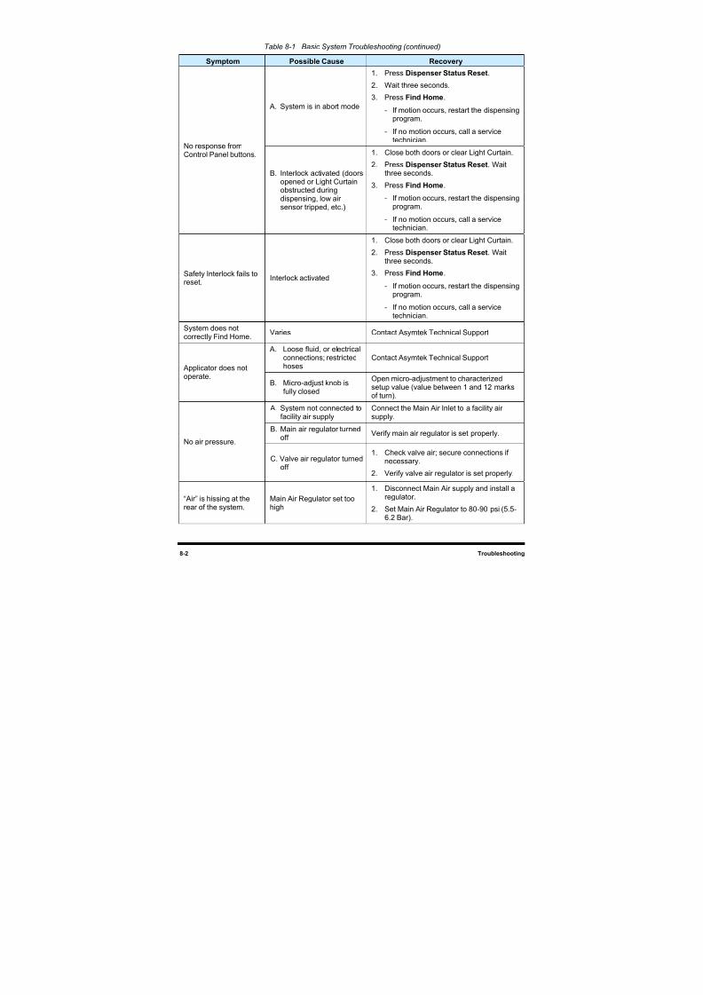
8/16/2019 Dispensig c 740 nordson
http://slidepdf.com/reader/full/dispensig-c-740-nordson 166/240

8/16/2019 Dispensig c 740 nordson
http://slidepdf.com/reader/full/dispensig-c-740-nordson 167/240
Troubleshooting 8-3
Table 8-1 Basic System Troubleshooting (continued)
Symptom Possible Cause Recovery
A. Applicator ON/OFFbutton is OFF
Press Applic ON/OFF button.
B. Out of fluid Add fluid to reservoir.
C. Nozzle is clogged
Remove nozzle, visually verify that it is
clogged. See the applicable FluidDispensing Applicator manual for cleaninginstructions.
D. Not enough fluid pressureor no fluid pressure
Increase fluid pressure. If equipped withMaterial Change Over option, verify valvesare set to correct reservoir.
No fluid is beingdispensed.
E. Micro-adjust knob is fullyclosed
Open micro-adjustment to characterizedsetup value (value between 1 and 12marks of turn).
A. Activation of EMO buttonmay offset positioning
Reinitiate the move sequence with the FindX-Y home command at the beginning of thesequence.
B. Excess payload for theavailable accelerationmay offset positioning
Change the acceleration values in themove sequence. Contact AsymtekTechnical Support for assistance.
C. Tool offset incorrectReconfigure Tool and perform aCharacterization.
Dispensing head runsinto fixed objects.
D. Dispense program tooclose to fixed objects
Dispensing program may need to beedited.
Stop Pins, BoardPins, or Bar Clampsdo not work.
Air pressure too lowCheck Main air pressure (80 to 90 psi) andConveyor air pressure (30 to 40 psi).
No upstream ordownstream interface.
Varies Call a service technician.
Part Sensor notsensing when boardis present.
Sensor is dirty, not active, orneeds to be adjusted
Clean Part Sensor, check sensor I/O, oradjust sensor sensitivity.
Board will not indexafter dispensing.
No SMEMA signal fromdownstream system
Call a service technician.
A. Stop Pin not receivingair
Call a service technician.
B. Part Sensor dirty Clean Part Sensor.Board will not index to
correct position. C. Conveyor rails too closetogether
Adjust width between Conveyor rails.
A. Accumulated debris inchain
Use an airgun or dry, clean cloth to removedebris from the Conveyor chain.Conveyor chain
movement is erraticor unsteady. B. Conveyor chain is loose
Tighten chain by repositioningConveyor motor (motor weight providesadequate tension).

8/16/2019 Dispensig c 740 nordson
http://slidepdf.com/reader/full/dispensig-c-740-nordson 168/240
8/16/2019 Dispensig c 740 nordson
http://slidepdf.com/reader/full/dispensig-c-740-nordson 169/240
Maintenance 9-1
9 Maintenance
9.1 Overview
Performing the recommended maintenance procedures at the intervals suggested in this section increases
system life and ensures high quality dispensing performance for every production run. This section covers
the following topics:
Hazardous Materials
Record Keeping
Routine Maintenance Procedures
Filling the Fluid Reservoir
Changing Material/Flushing Fluid System
Emptying the Water Trap
Cleaning the Fluid Filter
Lubricating the Mechanical Drive Cables
X-Axis Lubrication
Lubricating the X-Axis Bearings
Tensioning the Cables
9.2 Safety First
Before performing maintenance procedures, please familiarize yourself with the important information
provided in Section 2 - Safety. When performing maintenance, it is essential that you obey all written
safety warnings and the warning labels affixed to your dispensing system.
WARNING! Allow only qualified personnel to perform the following tasks. Observe and followthe safety instructions in this document and all other related documentation.
9.3 Hazardous Materials
Some maintenance procedures involve the use of hazardous materials. Always follow all applicable
national and local statutes and regulations, facility safety practice, and the material manufacturer's MSDS
recommendations.
9.4 Record Keeping
The type of maintenance performed (such as preventive and parts replacement) should be recorded in
maintenance records for the dispensing system. Dates, part numbers/serial numbers of replaced parts,
names of technicians, and other pertinent data should be recorded.
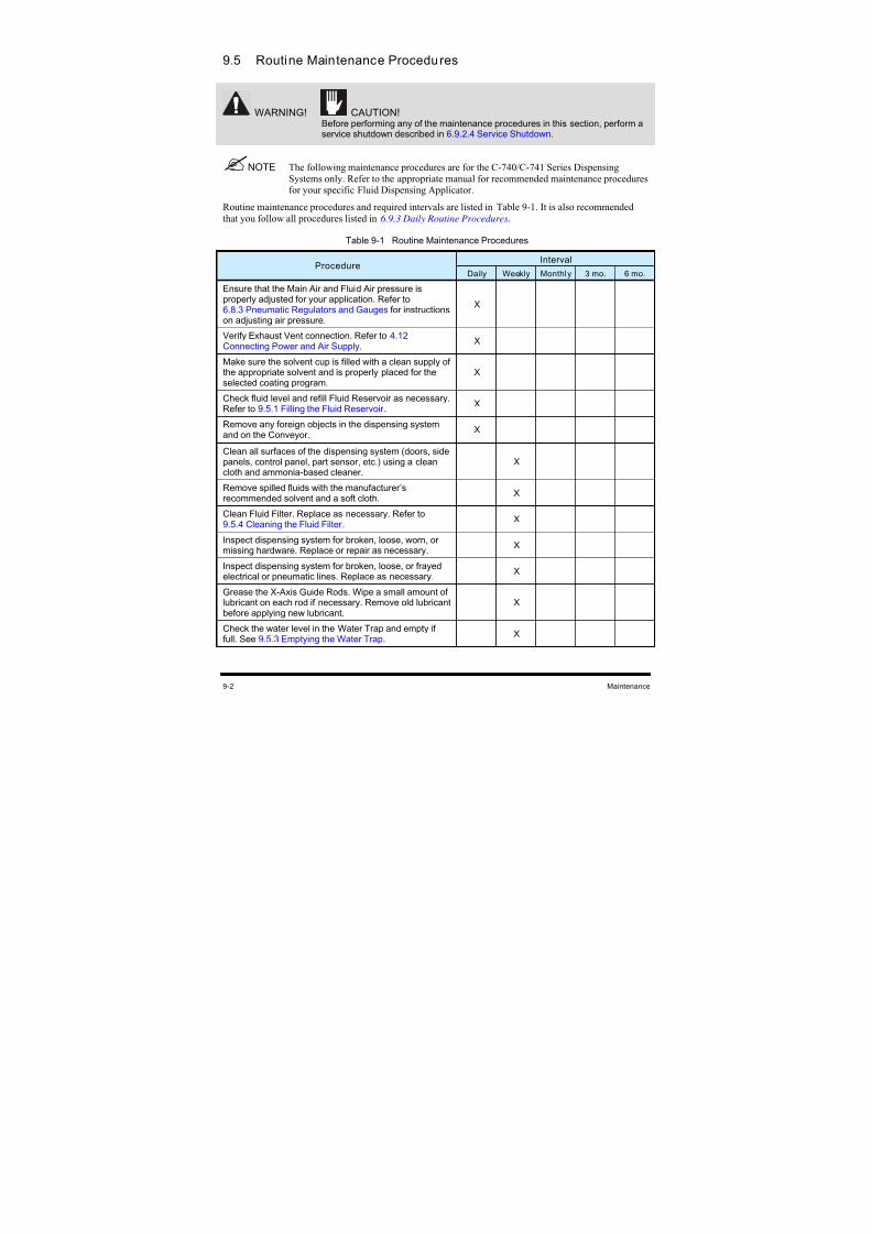
8/16/2019 Dispensig c 740 nordson
http://slidepdf.com/reader/full/dispensig-c-740-nordson 170/240
9-2 Maintenance
9.5 Routine Maintenance Procedures
WARNING! CAUTION!
Before performing any of the maintenance procedures in this section, perform aservice shutdown described in 6.9.2.4 Service Shutdown.
NOTE The following maintenance procedures are for the C-740/C-741 Series DispensingSystems only. Refer to the appropriate manual for recommended maintenance proceduresfor your specific Fluid Dispensing Applicator.
Routine maintenance procedures and required intervals are listed in Table 9-1. It is also recommended
that you follow all procedures listed in 6.9.3 Daily Routine Procedures.
Table 9-1 Routine Maintenance Procedures
IntervalProcedure
Daily Weekly Monthly 3 mo. 6 mo.
Ensure that the Main Air and Fluid Air pressure isproperly adjusted for your application. Refer to6.8.3 Pneumatic Regulators and Gauges for instructionson adjusting air pressure.
X
Verify Exhaust Vent connection. Refer to 4.12 Connecting Power and Air Supply.
X
Make sure the solvent cup is filled with a clean supply ofthe appropriate solvent and is properly placed for theselected coating program.
X
Check fluid level and refill Fluid Reservoir as necessary.Refer to 9.5.1 Filling the Fluid Reservoir .
X
Remove any foreign objects in the dispensing systemand on the Conveyor.
X
Clean all surfaces of the dispensing system (doors, sidepanels, control panel, part sensor, etc.) using a cleancloth and ammonia-based cleaner.
X
Remove spilled fluids with the manufacturer’srecommended solvent and a soft cloth.
X
Clean Fluid Filter. Replace as necessary. Refer to9.5.4 Cleaning the Fluid Filter .
X
Inspect dispensing system for broken, loose, worn, ormissing hardware. Replace or repair as necessary.
X
Inspect dispensing system for broken, loose, or frayedelectrical or pneumatic lines. Replace as necessary.
X
Grease the X-Axis Guide Rods. Wipe a small amount oflubricant on each rod if necessary. Remove old lubricantbefore applying new lubricant.
X
Check the water level in the Water Trap and empty iffull. See 9.5.3 Emptying the Water Trap.
X
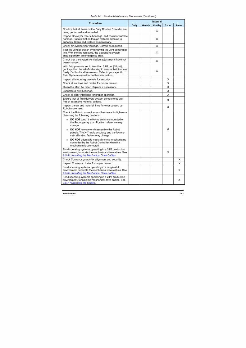
8/16/2019 Dispensig c 740 nordson
http://slidepdf.com/reader/full/dispensig-c-740-nordson 171/240
Maintenance 9-3
Table 9-1 Routine Maintenance Procedures (Continued)
IntervalProcedure
Daily Weekly Monthly 3 mo. 6 mo.
Confirm that all items on the Daily Routine Checklist arebeing performed and recorded.
X
Inspect Conveyor rollers, bearings, and chain for surface
damage. Ensure that no foreign material adheres tosurfaces. Clean and replace as necessary.
X
Check air cylinders for leakage. Correct as required. X
Test the vent air switch by removing the vent-sensing airline. With the line removed, the dispensing systemshould perform an emergency stop.
X
Check that the system ventilation adjustments have notbeen changed.
X
With fluid pressure set to less than 0.69 bar (10 psi),gently pull on the relief valve ring to ensure that it movesfreely. Do this for all reservoirs. Refer to your specificFluid System manual for further information.
X
Inspect all mounting brackets for security. X
Check all air lines and cables for proper tension. X
Clean the Main Air Filter. Replace if necessary. X
Lubricate X-axis bearings. X
Check all door interlocks for proper operation. X
Ensure that all fluid delivery system components arefree of excessive material buildup.
X
Inspect the air and material lines for wear caused byRobot movement.
X
Check the Robot connectors and hardware for tightnessobserving the following cautions.
DO NOT touch the Home switches mounted onthe Robot gantry axis. Position reference maychange.
DO NOT remove or disassemble the Robotpanels. The X-Y table accuracy and the factory-set calibration factors may change.
DO NOT attempt to manually move mechanismscontrolled by the Robot Controller when themechanism is connected.
X
For dispensing systems operating in a 24/7 productionenvironment, lubricate the mechanical drive cables. See 9.5.5 Lubricating the Mechanical Drive Cables.
X
Check Conveyor guards for alignment and security. X
Inspect Conveyor chains for proper tension. X
For dispensing systems operating in a single-shiftenvironment, lubricate the mechanical drive cables. See 9.5.5 Lubricating the Mechanical Drive Cables.
X
For dispensing systems operating in a 24/7 productionenvironment, tension the mechanical drive cables. See 9.5.7 Tensioning the Cables.
X
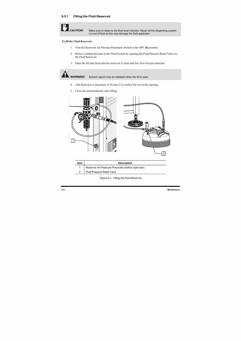
8/16/2019 Dispensig c 740 nordson
http://slidepdf.com/reader/full/dispensig-c-740-nordson 172/240
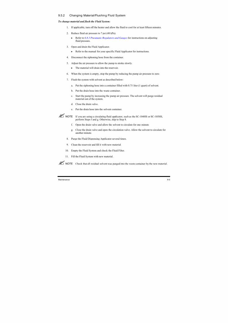
8/16/2019 Dispensig c 740 nordson
http://slidepdf.com/reader/full/dispensig-c-740-nordson 173/240
Maintenance 9-5
9.5.2 Changing Material/Flushing Fluid System
To change material and flush the Fluid System:
1.
If applicable, turn off the heater and allow the fluid to cool for at least fifteen minutes.
2. Reduce fluid air pressure to 7 psi (48 kPa).
Refer to 6.8.3 Pneumatic Regulators and Gauges for instructions on adjusting
fluid pressure.
3.
Open and drain the Fluid Applicator.
Refer to the manual for your specific Fluid Applicator for instructions.
4. Disconnect the siphoning hose from the container.
5. Adjust the air pressure to allow the pump to stroke slowly.
The material will drain into the reservoir.
6.
When the system is empty, stop the pump by reducing the pump air pressure to zero.
7. Flush the system with solvent as described below:
a.
Put the siphoning hose into a container filled with 0.75 liter (1 quart) of solvent.
b. Put the drain hose into the waste container.
c. Start the pump by increasing the pump air pressure. The solvent will purge residual
material out of the system.
d. Close the drain valve.
e.
Put the drain hose into the solvent container.
NOTE If you are using a circulating fluid applicator, such as the SC-104HS or SC-105HS, perform Steps f and g. Otherwise, skip to Step 8.
f. Open the drain valve and allow the solvent to circulate for one minute.
g. Close the drain valve and open the circulation valve. Allow the solvent to circulate for
another minute.
8. Purge the Fluid Dispensing Applicator several times.
9. Clean the reservoir and fill it with new material.
10. Empty the Fluid System and check the Fluid Filter.
11. Fill the Fluid System with new material.
NOTE Check that all residual solvent was purged into the waste container by the new material.
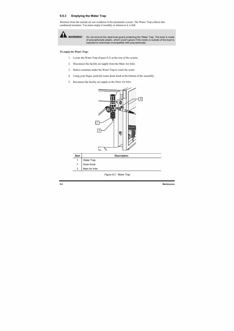
8/16/2019 Dispensig c 740 nordson
http://slidepdf.com/reader/full/dispensig-c-740-nordson 174/240
9-6 Maintenance
9.5.3 Emptying the Water Trap
Moisture from the outside air can condense in the pneumatic system. The Water Trap collects this
condensed moisture. You must empty it monthly or whenever it is full.
WARNING! Do not remove the steel bowl guard protecting the Water Trap. The bowl is madeof polycarbonate plastic, which could rupture if the inside or outside of the bowl isexposed to chemicals incompatible with polycarbonate.
To empty the Water Trap:
1. Locate the Water Trap (Figure 9-2) at the rear of the system.
2. Disconnect the facility air supply from the Main Air Inlet.
3. Hold a container under the Water Trap to catch the water.
4. Using your finger, push the water drain knob at the bottom of the assembly.
5. Reconnect the facility air supply to the Main Air Inlet.
Item Description
1 Water Trap
2 Drain Knob
3 Main Air Inlet
Figure 9-2 Water Trap
2
1
3
8/16/2019 Dispensig c 740 nordson
http://slidepdf.com/reader/full/dispensig-c-740-nordson 175/240
Maintenance 9-7
9.5.4 Cleaning the Fluid Filter
To clean the Fluid Filter:
1. Turn the Reservoir Air Pressure Pneumatic Switch to the OFF (0) position. See Figure 9-3.
2. Relieve residual pressure in the Fluid System by opening the Pressure Relief Valve on the
Fluid Reservoir.
WARNING! To prevent eye injury or irritation, wear safety goggles while performing thisprocedure.
3. Unscrew the Fluid Filter cap.
The Fluid Filter is located inside the housing.
4. Remove the 150-micron in-line filter and clean it with a proper solvent.
5. Brush the stainless steel screen with the appropriate solvent. Replace if necessary.
6. Blow filter surface with compressed air.
Item Description
1 Fluid Filter Cap (left rear)
2 Reservoir Air Pressure Pneumatic Switch (right rear)
3 Fluid Reservoir Pressure Relief Valve
Figure 9-3 Cleaning the Fluid Filter
12
3
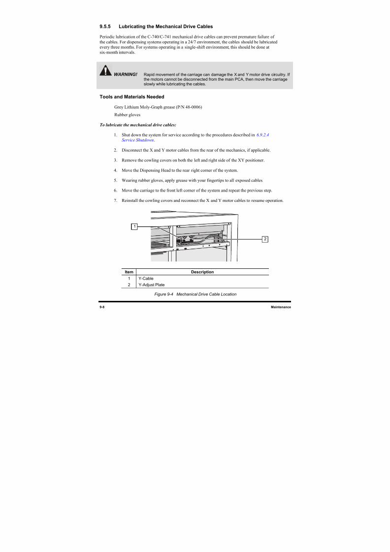
8/16/2019 Dispensig c 740 nordson
http://slidepdf.com/reader/full/dispensig-c-740-nordson 176/240
9-8 Maintenance
9.5.5 Lubricating the Mechanical Drive Cables
Periodic lubrication of the C-740/C-741 mechanical drive cables can prevent premature failure of
the cables. For dispensing systems operating in a 24/7 environment, the cables should be lubricated
every three months. For systems operating in a single-shift environment, this should be done at
six-month intervals.
WARNING! Rapid movement of the carriage can damage the X and Y motor drive circuitry. Ifthe motors cannot be disconnected from the main PCA, then move the carriageslowly while lubricating the cables.
Tools and Materials Needed
Grey Lithium Moly-Graph grease (P/N 48-0006)
Rubber gloves
To lubricate the mechanical drive cables:
1. Shut down the system for service according to the procedures described in 6.9.2.4
Service Shutdown.
2. Disconnect the X and Y motor cables from the rear of the mechanics, if applicable.
3. Remove the cowling covers on both the left and right side of the XY positioner.
4. Move the Dispensing Head to the rear right corner of the system.
5. Wearing rubber gloves, apply grease with your fingertips to all exposed cables.
6. Move the carriage to the front left corner of the system and repeat the previous step.
7. Reinstall the cowling covers and reconnect the X and Y motor cables to resume operation.
Item Description
1 Y-Cable
2 Y-Adjust Plate
Figure 9-4 Mechanical Drive Cable Location
1
2
8/16/2019 Dispensig c 740 nordson
http://slidepdf.com/reader/full/dispensig-c-740-nordson 177/240
Maintenance 9-9
9.5.6 X-Axis Lubrication
Lubricating the X-axis bearings on a quarterly basis will ensure smooth Dispensing Head movement and
prolong bearing life.
Tools and Materials Needed
• Grease Gun, 16 oz. Cartridge (P/N 09-2010-00)
• Grease Fitting (P/N 43-1064-30)
• Grease, Linear Lube (P/N 48-0019)
• Ammonia-based Cleaner
• Soft Cloth
9.5.6.1 Loading the Grease Gun
To load the grease gun:
1. Pull the grease gun handle back until the locking tabs are visible.
2. Twist the lock into position.
3. Unscrew and remove the top of the grease gun.
4. Remove the cap from the grease cartridge and place the cartridge open end down into the
gun cylinder.
5. Pull the tab to remove the seal from the bottom of the grease cartridge.
6. Replace the top of the grease gun, and screw the extension into the front side at the top of the
grease gun.
7. Release the handle from the locked position.
8. Purge the air from the grease gun cartridge by dispensing grease until a solid stream flows
from the gun.
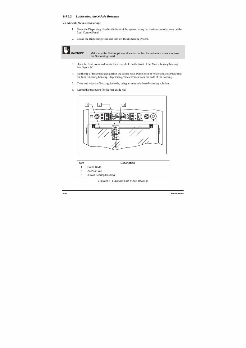
8/16/2019 Dispensig c 740 nordson
http://slidepdf.com/reader/full/dispensig-c-740-nordson 178/240
9-10 Maintenance
9.5.6.2 Lubricating the X-Axis Bearings
To lubricate the X-axis bearings:
1. Move the Dispensing Head to the front of the system, using the motion control arrows on thefront Control Panel.
2. Lower the Dispensing Head and turn off the dispensing system.
CAUTION! Make sure the Fluid Applicator does not contact the substrate when you lowerthe Dispensing Head.
3. Open the front doors and locate the access hole on the front of the X-axis bearing housing.
See Figure 9-5.
4. Put the tip of the grease gun against the access hole. Pump once or twice to inject grease into
the X-axis bearing housing. Stop when grease extrudes from the ends of the housing.
5. Clean and wipe the X-axis guide rods, using an ammonia-based cleaning solution.
6. Repeat the procedure for the rear guide rod.
Item Description
1 Guide Rods
2 Access Hole
3 X-Axis Bearing Housing
Figure 9-5 Lubricating the X-Axis Bearings
1 2 3
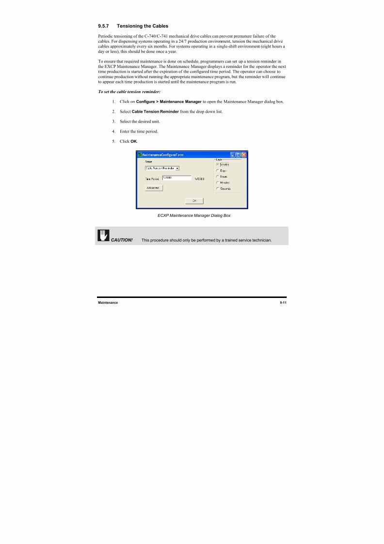
8/16/2019 Dispensig c 740 nordson
http://slidepdf.com/reader/full/dispensig-c-740-nordson 179/240
Maintenance 9-11
9.5.7 Tensioning the Cables
Periodic tensioning of the C-740/C-741 mechanical drive cables can prevent premature failure of the
cables. For dispensing systems operating in a 24/7 production environment, tension the mechanical drive
cables approximately every six months. For systems operating in a single-shift environment (eight hours a
day or less), this should be done once a year.
To ensure that required maintenance is done on schedule, programmers can set up a tension reminder inthe EXCP Maintenance Manager. The Maintenance Manager displays a reminder for the operator the next
time production is started after the expiration of the configured time period. The operator can choose to
continue production without running the appropriate maintenance program, but the reminder will continue
to appear each time production is started until the maintenance program is run.
To set the cable tension reminder:
1. Click on Configure > Maintenance Manager to open the Maintenance Manager dialog box.
2. Select Cable Tension Reminder from the drop down list.
3. Select the desired unit.
4. Enter the time period.
5. Click OK.
ECXP Maintenance Manager Dialog Box
CAUTION! This procedure should only be performed by a trained service technician.
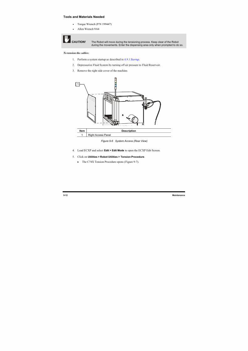
8/16/2019 Dispensig c 740 nordson
http://slidepdf.com/reader/full/dispensig-c-740-nordson 180/240
9-12 Maintenance
Tools and Materials Needed
• Torque Wrench (P/N 199447)
• Allen Wrench 9/64
CAUTION! The Robot will move during the tensioning process. Keep clear of the Robotduring the movements. Enter the dispensing area only when prompted to do so.
To tension the cables:
1. Perform a system startup as described in 6.9.1 Startup.
2. Depressurize Fluid System by turning off air pressure to Fluid Reservoir.
3. Remove the right side cover of the machine.
Item Description
1 Right Access Panel
Figure 9-6 System Access (Rear View)
4. Load ECXP and select Edit > Edit Mode to open the ECXP Edit Screen.
5. Click on Utilities > Robot Utilities > Tension Procedure.
The C74X Tension Procedure opens (Figure 9-7).
1
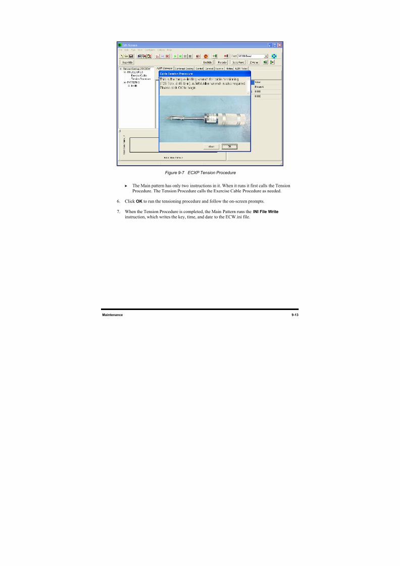
8/16/2019 Dispensig c 740 nordson
http://slidepdf.com/reader/full/dispensig-c-740-nordson 181/240
Maintenance 9-13
Figure 9-7 ECXP Tension Procedure
The Main pattern has only two instructions in it. When it runs it first calls the Tension
Procedure. The Tension Procedure calls the Exercise Cable Procedure as needed.
6. Click OK to run the tensioning procedure and follow the on-screen prompts.
7. When the Tension Procedure is completed, the Main Pattern runs the INI File Write
instruction, which writes the key, time, and date to the ECW.ini file.

8/16/2019 Dispensig c 740 nordson
http://slidepdf.com/reader/full/dispensig-c-740-nordson 182/240
8/16/2019 Dispensig c 740 nordson
http://slidepdf.com/reader/full/dispensig-c-740-nordson 183/240
Parts Replacement 10-1
10 Parts Replacement
10.1 Overview
This section includes general information for ordering recommended spares and replacement parts for
your Century C-740/C-741 Dispensing System. Part numbers can be found on the exploded parts
diagrams in Appendix C . This section also contains the following procedures:
• Parts Ordering Information
• Unpacking and Inspecting Replacement Parts
• Gaining Access to Dispensing System Components
• Replacing Conveyor Chains (C-740)
• Replacing Fuses
• Replacing Control Modules
NOTE This section does not include the removal and replacement of Fluid Dispensing
Applicator components. Refer to the manual for your specific fluid applicator forrecommended maintenance procedures.
10.2 Safety First
Review the precautions in Section 2 - Safety before attempting to replace any parts.
WARNING! Parts replacement should only be performed by a trained service technician. Asymtek assumes no liability for personal injury or property damage that mayoccur as a result of spare parts being replaced by other than Asymtek-trainedtechnicians.
10.2.1 Hazardous Materials
Some part replacement procedures involve the use and disposal of hazardous materials. Always followthe material manufacturer MSDS, facility requirements, and local regulations for protection of personnel
and disposal of materials.
8/16/2019 Dispensig c 740 nordson
http://slidepdf.com/reader/full/dispensig-c-740-nordson 184/240
10-2 Parts Replacement
10.3 Parts Ordering Information
10.3.1 Placing Your Order
Customers can order spare parts by contacting Asymtek Customer Service. Your Customer Service
Representative can take your order or assist you in setting up an account to purchase spare parts through
our Internet Web Store. When ordering parts, be prepared to provide the following information:
Your Company Name Billing Address
Shipping Address Part Number and Description of Part
Purchase Order Number Quantity
Dispensing System Serial Number
(found on back panel)
Shipping Instructions with Collect
Account Number
NOTE Find Customer Service contact information in the front of this manual or click onCustomer Service on Asymtek web page 1www.asymtek.com.
10.3.2 Shipping Instructions
When ordering parts, specify which carrier you prefer to use and provide your shipping account number.
If no instructions are received, Asymtek will determine the best shipping method and items will be
shipped prepaid with the shipping charge added to the invoice.
10.3.3 Warranty
Contact Asymtek Technical Support for any warranty issues pertaining to spare parts.
10.3.4 Credit and Exchanges
Contact Asymtek Customer Service for credit or exchanges of recommended spare parts or refurbished
components (components restored to original specifications but not sold as new).
10.3.5 Return Material Authorization
Contact Asymtek Technical Support to obtain a Return Material Authorization (RMA) before returning
any parts.
NOTE Find your local Technical Support contact on the Asymtek web page,
2H
www.asymtek.com/support.htm.
8/16/2019 Dispensig c 740 nordson
http://slidepdf.com/reader/full/dispensig-c-740-nordson 185/240
Parts Replacement 10-3
10.4 Cleaning and Inspection
Always clean the area made visible after a failed part is removed from the dispensing system. Inspect the
area for signs of what may have caused the part to fail. This may help prevent future part damage.
While removing parts that will be reinstalled, visually inspect them for damage. If found undamaged,
retain them for reinstallation. Replace damaged parts and hardware as appropriate.
10.5 Unpacking and Inspecting Replacement Parts
Replacement parts are shipped to distributor or Customer facilities in individual shipping cartons. Review
the packing slip to ensure that the correct parts were received. Contact Asymtek Technical Support if any
discrepancies are discovered.
Before unpacking your spare parts, visually inspect the carton for damage. If applicable, check the
ShockWatch and the Tip N’ Tell stickers for indications of improper shipping and handling. Inform the
freight carrier of any damage.
TIP Save shipping materials for returning failed parts.
10.6 Record Keeping
The type of service performed should be recorded in the dispensing system maintenance records. Dates,
part numbers/serial numbers of replaced parts, names of technicians, and other pertinent data should be
recorded.
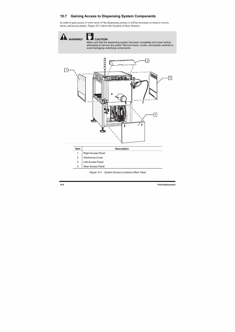
8/16/2019 Dispensig c 740 nordson
http://slidepdf.com/reader/full/dispensig-c-740-nordson 186/240
10-4 Parts Replacement
10.7 Gaining Access to Dispensing System Components
In order to gain access to some areas of the dispensing system, it will be necessary to remove covers,
doors, and access panels. 9HFigure 10-1 shows the location of these features.
WARNING! CAUTION! Make sure that the dispensing system has been completely shut down beforeattempting to remove any panel. Remove doors, covers, and panels carefully toavoid damaging underlying components.
Item Description
1 Right Access Panel
2 Electronics Cover
3 Left Access Panel
4 Rear Access Panel
Figure 10-1 System Access Locations (Rear View)
1
2
3
4
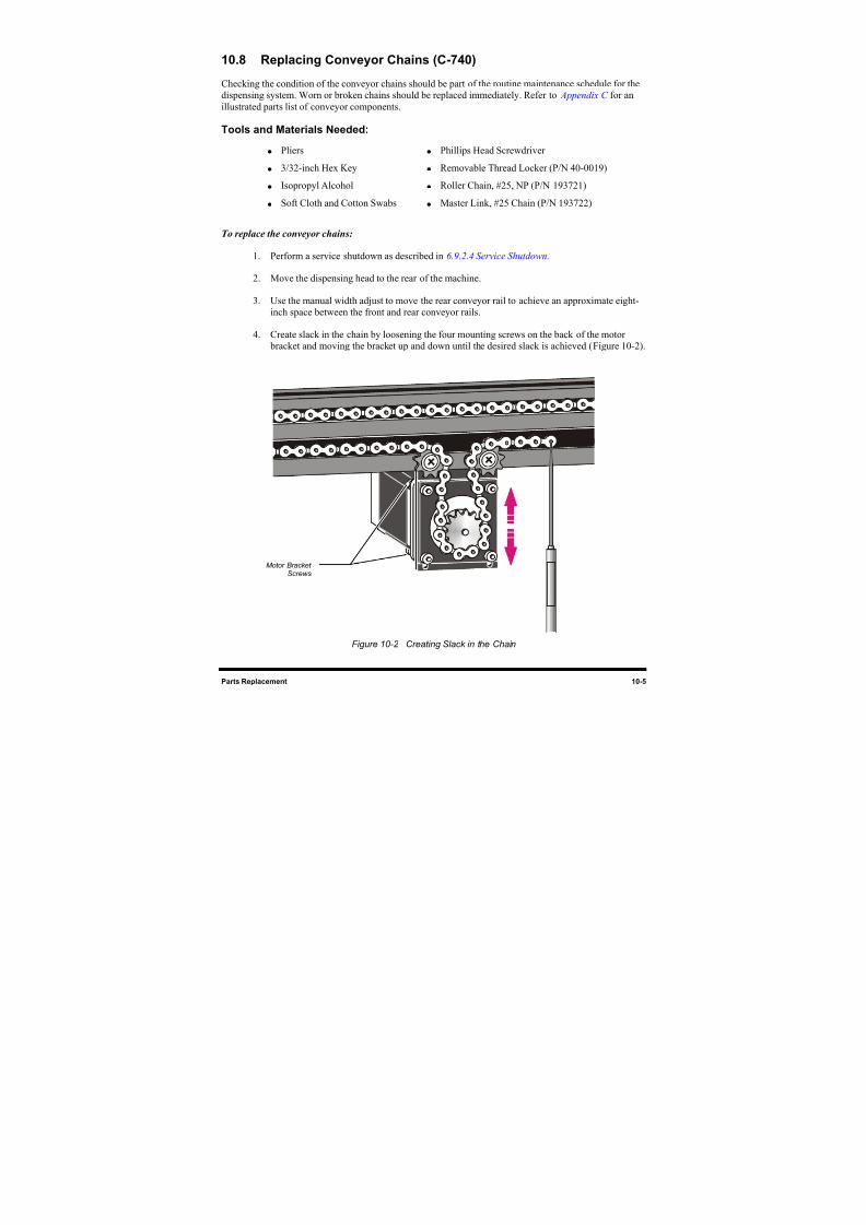
8/16/2019 Dispensig c 740 nordson
http://slidepdf.com/reader/full/dispensig-c-740-nordson 187/240
Parts Replacement 10-5
10.8 Replacing Conveyor Chains (C-740)
Checking the condition of the conveyor chains should be part of the routine maintenance schedule for the
dispensing system. Worn or broken chains should be replaced immediately. Refer to Appendix C for an
illustrated parts list of conveyor components.
Tools and Materials Needed:
Pliers Phillips Head Screwdriver
3/32-inch Hex Key Removable Thread Locker (P/N 40-0019)
Isopropyl Alcohol Roller Chain, #25, NP (P/N 193721)
Soft Cloth and Cotton Swabs Master Link, #25 Chain (P/N 193722)
To replace the conveyor chains:
1. Perform a service shutdown as described in 6.9.2.4 Service Shutdown.
2. Move the dispensing head to the rear of the machine.
3. Use the manual width adjust to move the rear conveyor rail to achieve an approximate eight-
inch space between the front and rear conveyor rails.
4. Create slack in the chain by loosening the four mounting screws on the back of the motor
bracket and moving the bracket up and down until the desired slack is achieved (10H
Figure 10-2).
Figure 10-2 Creating Slack in the Chain
Motor BracketScrews
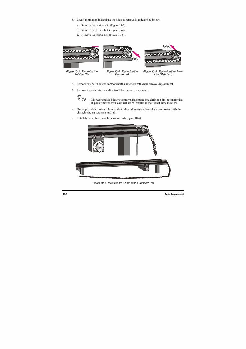
8/16/2019 Dispensig c 740 nordson
http://slidepdf.com/reader/full/dispensig-c-740-nordson 188/240
10-6 Parts Replacement
5. Locate the master link and use the pliers to remove it as described below:
a. Remove the retainer clip (11HFigure 10-3).
b. Remove the female link ( 12HFigure 10-4).
c. Remove the master link (13H
Figure 10-5).
Figure 10-3 Removing theRetainer Clip
Figure 10-4 Removing theFemale Link
Figure 10-5 Removing the MasterLink (Male Link)
6. Remove any rail-mounted components that interfere with chain removal/replacement.
7. Remove the old chain by sliding it off the conveyor sprockets.
TIP It is recommended that you remove and replace one chain at a time to ensure that
all parts removed from each rail are re-installed in their exact same locations.
8. Use isopropyl alcohol and clean swabs to clean all metal surfaces that make contact with the
chain, including sprockets and rails.
9. Install the new chain onto the sprocket rail (14H
Figure 10-6).
Figure 10-6 Installing the Chain on the Sprocket Rail
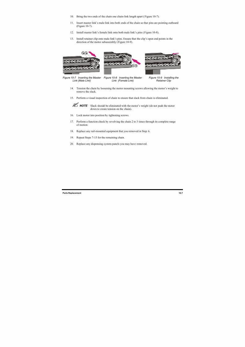
8/16/2019 Dispensig c 740 nordson
http://slidepdf.com/reader/full/dispensig-c-740-nordson 189/240
Parts Replacement 10-7
10. Bring the two ends of the chain one chain-link length apart (15H
Figure 10-7).
11. Insert master link’s male link into both ends of the chain so that pins are pointing outboard
(16H
Figure 10-7).
12. Install master link’s female link onto both male link’s pins (17H
Figure 10-8).
13. Install retainer clip onto male link’s pins. Ensure that the clip’s open end points in thedirection of the motor subassembly ( 18HFigure 10-9).
Figure 10-7 Inserting the MasterLink (Male Link) Figure 10-8 Inserting the MasterLink (Female Link) Figure 10-9 Installing theRetainer Clip
14. Tension the chain by loosening the motor mounting screws allowing the motor’s weight to
remove the slack.
15. Perform a visual inspection of chain to ensure that slack from chain is eliminated.
NOTE Slack should be eliminated with the motor’s weight (do not push the motordown to create tension on the chain).
16. Lock motor into position by tightening screws.
17. Perform a function check by revolving the chain 2 to 3 times through its complete range
of motion.
18. Replace any rail-mounted equipment that you removed in Step19H
6.
19. Repeat Steps 20H7-21H15 for the remaining chain.
20. Replace any dispensing system panels you may have removed.
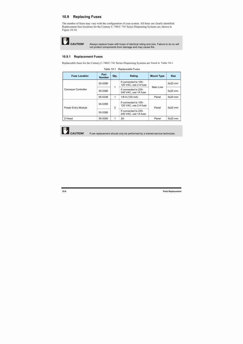
8/16/2019 Dispensig c 740 nordson
http://slidepdf.com/reader/full/dispensig-c-740-nordson 190/240
10-8 Parts Replacement
10.9 Replacing Fuses
The number of fuses may vary with the configuration of your system. All fuses are clearly identified.
Replacement fuse locations for the Century C-740/C-741 Series Dispensing Systems are shown in
22H
Figure 10-10.
CAUTION! Always replace fuses with fuses of identical rating and size. Failure to do so willnot protect components from damage and may cause fire.
10.9.1 Replacement Fuses
Replaceable fuses for the Century C-740/C-741 Series Dispensing Systems are listed in 23HTable 10-1.
Table 10-1 Replaceable Fuses
Fuse LocationPart
NumberQty. Rating Mount Type Size
55-5390If connected to 100–120 VAC, use 2 A fuse
5x20 mm
55-5380
1If connected to 220-240 VAC, use 1A fuse
Main Line
5x20 mmConveyor Controller
55-5336 1 1/8 A (125 mA) Panel 5x20 mm
55-5390If connected to 100–120 VAC, use 2 A fuse
Power Entry Module
55-5380
2
If connected to 220-240 VAC, use 1A fuse
Panel 5x20 mm
Z-Head 55-5390 1 2A Panel 5x20 mm
CAUTION! Fuse replacement should only be performed by a trained service technician.
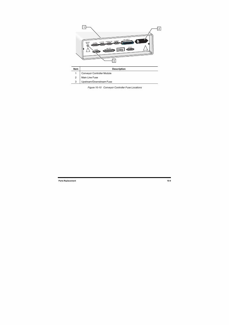
8/16/2019 Dispensig c 740 nordson
http://slidepdf.com/reader/full/dispensig-c-740-nordson 191/240
8/16/2019 Dispensig c 740 nordson
http://slidepdf.com/reader/full/dispensig-c-740-nordson 192/240
10-10 Parts Replacement
10.9.2 Replacing Main Line Fuses
CAUTION! This procedure should only be performed by a trained service technician.
Tools and Materials Needed
• ESD Grounding Strap • Replacement Fuse (see24H
Table 10-1)
• Small Flat Head Screwdriver
To replace a main line fuse:
1. Perform a service shutdown as described in 6.9.2.4 Service Shutdown.
WARNING! Make sure that all electrical and pneumatic power supplies have been turned offand disconnected as described in 6.9.2.4 Service Shutdown . Failure to do somay cause serious injury or death.
2. Determine which fuse needs to be replaced.
3. Insert the small flat head screwdriver into the slot at the top or on the side of the fuse box and
gently pry it open.
The main line fuse on the Conveyor Controller Module is in a box that detaches from the
module. Inside of this fuse box, there are two fuses. Both fuses are active.
See 25HFigure 10-11.
4. Using your fingers, remove the damaged fuse.
If necessary, poke the small flat head screwdriver through the hole in the back of the fuse
box and push the fuse out from behind.
5. Replace the damaged fuse with the proper replacement fuse.
CAUTION! Always replace fuses with fuses of identical rating and size. Failure to do so willnot protect components from damage and may cause fire.
6. Return the fuse box to its closed position.
7. Perform a system startup described in 6.9.1 Startup.
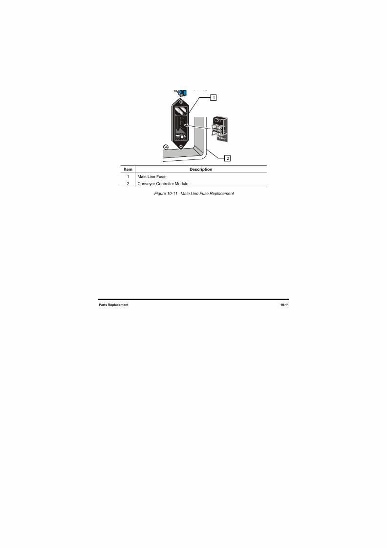
8/16/2019 Dispensig c 740 nordson
http://slidepdf.com/reader/full/dispensig-c-740-nordson 193/240
Parts Replacement 10-11
Item Description
1 Main Line Fuse
2 Conveyor Controller Module
Figure 10-11 Main Line Fuse Replacement
1
2
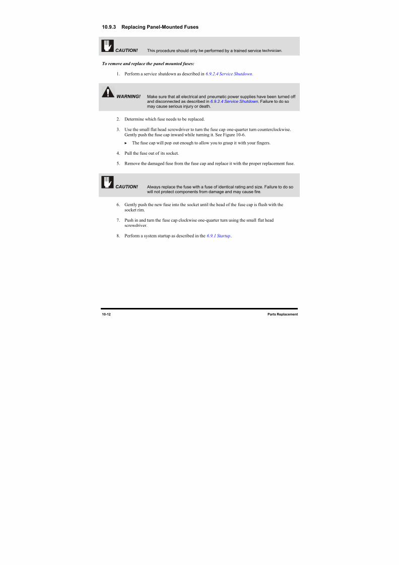
8/16/2019 Dispensig c 740 nordson
http://slidepdf.com/reader/full/dispensig-c-740-nordson 194/240
10-12 Parts Replacement
10.9.3 Replacing Panel-Mounted Fuses
CAUTION! This procedure should only be performed by a trained service technician.
To remove and replace the panel mounted fuses:
1. Perform a service shutdown as described in 6.9.2.4 Service Shutdown.
WARNING! Make sure that all electrical and pneumatic power supplies have been turned offand disconnected as described in 6 .9.2.4 Service Shutdown. Failure to do somay cause serious injury or death.
2. Determine which fuse needs to be replaced.
3. Use the small flat head screwdriver to turn the fuse cap one-quarter turn counterclockwise.
Gently push the fuse cap inward while turning it. See Figure 10-6.
The fuse cap will pop out enough to allow you to grasp it with your fingers.
4. Pull the fuse out of its socket.
5. Remove the damaged fuse from the fuse cap and replace it with the proper replacement fuse.
CAUTION! Always replace the fuse with a fuse of identical rating and size. Failure to do so
will not protect components from damage and may cause fire.
6. Gently push the new fuse into the socket until the head of the fuse cap is flush with the
socket rim.
7. Push in and turn the fuse cap clockwise one-quarter turn using the small flat head
screwdriver.
8. Perform a system startup as described in the 6.9.1 Startup.
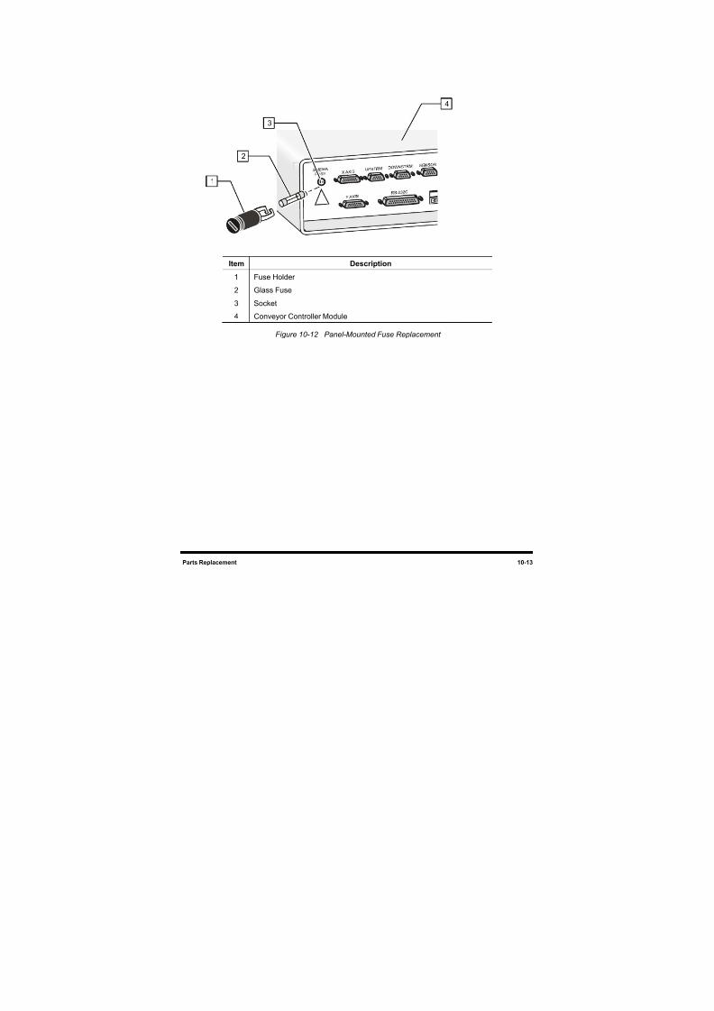
8/16/2019 Dispensig c 740 nordson
http://slidepdf.com/reader/full/dispensig-c-740-nordson 195/240
Parts Replacement 10-13
Item Description
1 Fuse Holder
2 Glass Fuse
3 Socket
4 Conveyor Controller Module
Figure 10-12 Panel-Mounted Fuse Replacement
4
3
2
1
8/16/2019 Dispensig c 740 nordson
http://slidepdf.com/reader/full/dispensig-c-740-nordson 196/240
10-14 Parts Replacement
10.10 Replacing Control Modules
CAUTION! This procedure should only be performed by a trained service technician.
Tools and Materials Needed
1/8-Inch Hex Key Removable Thread Locker (P/N 40-0019)
Clean Soft Cloth
To remove and replace a Control Module:
1. Perform a service shutdown as described 6.9.2.4 Service Shutdown.
WARNING! Make sure that all electrical and pneumatic power supplies have been turned offand disconnected as described in 6.9.2.4 Service Shutdown. Failure to do somay cause serious injury or death.
2. Open the rear cabinet door of the dispensing system and locate the failed module.
3. Check to make sure that all of the cables and pneumatic tubes (if applicable) are labeled. If a
cable or pneumatic tube is not labeled, label it according to its corresponding receptor.
4. Disconnect all cables and pneumatic tubes (if applicable) from the module.
To disconnect a pneumatic tube, push in the collar around the port and pull out the tube.
5. Use a 1/8-inch hex key to remove the four screws attaching the module to the frame.
CAUTION! When removing the module from its slot in the rear cabinet, support the moduleto prevent it from dropping. Dropping the module may damage internal parts.
6. Slide the module out of the rear cabinet.
The Conveyor Controller Module also has a cable connection on the backside that
connects to the Control Panel. Disconnect this cable before sliding it all the way out of itsslot.
7. Clean any dust and debris from the floor of the cabinet using a cloth dampened with water or
ammonia-based cleaner.
8. Gently slide the new module into the same slot from which you removed the old module.
For the Conveyor Controller Module, reinstall the cable connection on the backside
before sliding the module all the way into its slot.
8/16/2019 Dispensig c 740 nordson
http://slidepdf.com/reader/full/dispensig-c-740-nordson 197/240
Parts Replacement 10-15
9. Apply removable thread locker to the four attachment screws and install using the 1/8-inch
hex key.
10. Reconnect all cables, cords, and tubes (as applicable) to the appropriate module receptors.
11. To install a pneumatic tube, simply push the tube end into the port until you feel it lock.
12. Perform a system startup as described in 6.9.1 Startup.

8/16/2019 Dispensig c 740 nordson
http://slidepdf.com/reader/full/dispensig-c-740-nordson 198/240
8/16/2019 Dispensig c 740 nordson
http://slidepdf.com/reader/full/dispensig-c-740-nordson 199/240
Specifications 11-1
11 Specifications
11.1 Overview
Century C-740/C-741 Dispensing System specifications are presented in Tables 11-1 through 11-5. Thesespecifications are intended as a convenient reference for personnel planning system relocation,
installation, or operation, and others that may have an interest in system performance characteristics. Thissection provides specifications for the following:
• 0HFacility Requirements
•
1H
Drive System
• 2H
Conveyor
• 3HDispensing Area
• 4HSoftware
11.2 Safety FirstFamiliarity with the performance specifications and facility requirements in this section can provide
information leading to safe operation of the dispensing system. For additional safety information, refer to
Section 2 - Safety.
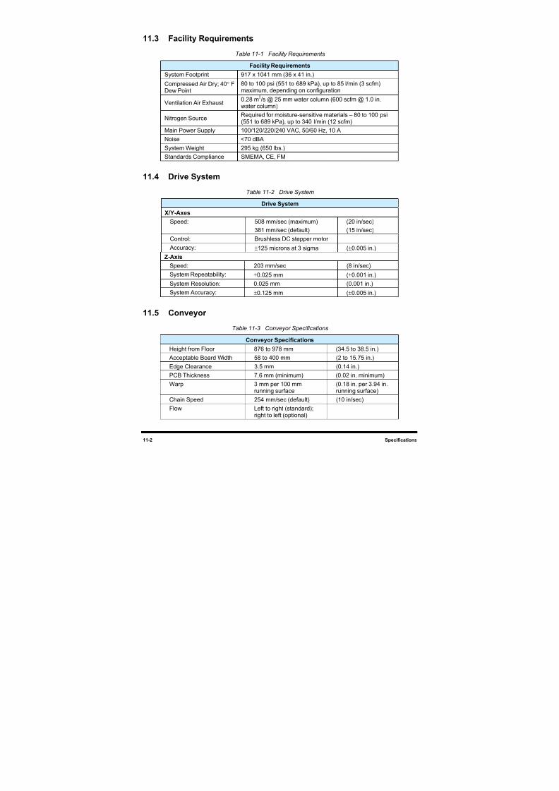
8/16/2019 Dispensig c 740 nordson
http://slidepdf.com/reader/full/dispensig-c-740-nordson 200/240
11-2 Specifications
11.3 Facility Requirements
Table 11-1 Facility Requirements
Facility Requirements
System Footprint 917 x 1041 mm (36 x 41 in.)
Compressed Air Dry; 40° F
Dew Point
80 to 100 psi (551 to 689 kPa), up to 85 l/min (3 scfm)
maximum, depending on configuration
Ventilation Air Exhaust0.28 m
3/s @ 25 mm water column (600 scfm @ 1.0 in.
water column)
Nitrogen SourceRequired for moisture-sensitive materials – 80 to 100 psi(551 to 689 kPa), up to 340 l/min (12 scfm)
Main Power Supply 100/120/220/240 VAC, 50/60 Hz, 10 A
Noise <70 dBA
System Weight 295 kg (650 lbs.)
Standards Compliance SMEMA, CE, FM
11.4 Drive SystemTable 11-2 Drive System
Drive System
X/Y-Axes
Speed: 508 mm/sec (maximum)
381 mm/sec (default)
(20 in/sec)
(15 in/sec)
Control: Brushless DC stepper motor
Accuracy: ±125 microns at 3 sigma (±0.005 in.)
Z-Axis
Speed: 203 mm/sec (8 in/sec)System Repeatability: ±0.025 mm (±0.001 in.)
System Resolution: 0.025 mm (0.001 in.)
System Accuracy: ±0.125 mm (±0.005 in.)
11.5 Conveyor
Table 11-3 Conveyor Specifications
Conveyor Specifications
Height from Floor 876 to 978 mm (34.5 to 38.5 in.)
Acceptable Board Width 58 to 400 mm (2 to 15.75 in.)Edge Clearance 3.5 mm (0.14 in.)
PCB Thickness 7.6 mm (minimum) (0.02 in. minimum)
Warp 3 mm per 100 mmrunning surface
(0.18 in. per 3.94 in.running surface)
Chain Speed 254 mm/sec (default) (10 in/sec)
Flow Left to right (standard);right to left (optional)
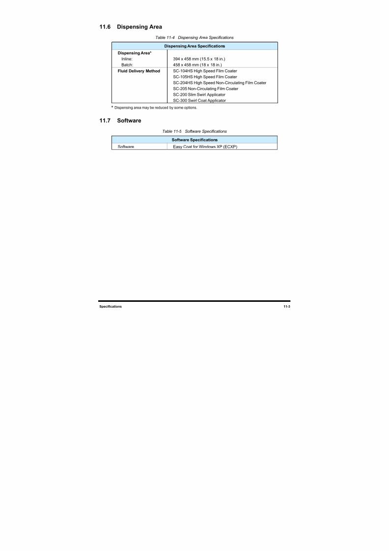
8/16/2019 Dispensig c 740 nordson
http://slidepdf.com/reader/full/dispensig-c-740-nordson 201/240
Specifications 11-3
11.6 Dispensing Area
Table 11-4 Dispensing Area Specifications
Dispensing Area Specifications
Dispensing Area*
Inline:
Batch:
394 x 458 mm (15.5 x 18 in.)
458 x 458 mm (18 x 18 in.)
Fluid Delivery Method SC-104HS High Speed Film Coater
SC-105HS High Speed Film Coater
SC-204HS High Speed Non-Circulating Film Coater
SC-205 Non-Circulating Film Coater
SC-200 Slim Swirl Applicator
SC-300 Swirl Coat Applicator
* Dispensing area may be reduced by some options.
11.7 Software
Table 11-5 Software Specifications
Software Specifications
Software Easy Coat for Windows XP (ECXP)

8/16/2019 Dispensig c 740 nordson
http://slidepdf.com/reader/full/dispensig-c-740-nordson 202/240
8/16/2019 Dispensig c 740 nordson
http://slidepdf.com/reader/full/dispensig-c-740-nordson 203/240
Appendix A - Pneumatic Diagrams A-1
Appendix A - Pneumatic Diagrams
A.1 Overview
This appendix contains block diagrams that describe the Century C-740/C-741 Series Dispensing System
pneumatic system. The diagrams may help in understanding dispensing system operation and aid in
troubleshooting. The diagrams included in this appendix are described in Table A-1.
NOTE The drawings included in this appendix are the latest revision in effect at the timeof publication. Contact Asymtek Technical Support to verify that you are using thecurrent revision.
A.2 Safety First
Use of engineering drawings to disassemble, service, and reassemble the dispensing system promotes
good safety practices only when used in conjunction with the precautions in Section 2 - Safety and other
sections of this manual.
CAUTION! Only Asymtek-trained service technicians should perform troubleshooting,servicing, and parts replacement.
A.3 List of Pneumatic Diagrams
Table A-1 Pneumatic Diagram
Drawing Number Title
194401PD Pneumatic Diagram, C-740/C-741

8/16/2019 Dispensig c 740 nordson
http://slidepdf.com/reader/full/dispensig-c-740-nordson 204/240
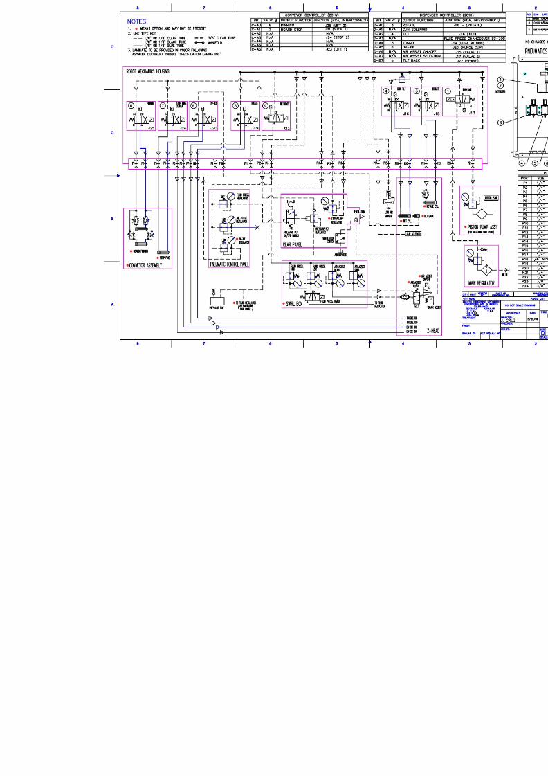
8/16/2019 Dispensig c 740 nordson
http://slidepdf.com/reader/full/dispensig-c-740-nordson 205/240

8/16/2019 Dispensig c 740 nordson
http://slidepdf.com/reader/full/dispensig-c-740-nordson 206/240
8/16/2019 Dispensig c 740 nordson
http://slidepdf.com/reader/full/dispensig-c-740-nordson 207/240
Appendix B - Electrical Diagrams B-1
Appendix B - Electrical Diagrams
B.1 Overview
This appendix contains diagrams that describe the Century C-740/C-741 Series Dispensing System
electrical systems. The diagrams may help in understanding dispensing system operation and aid in
troubleshooting. The diagrams included in this appendix are described in Table B-1.
NOTE The drawings included in this appendix are the latest revision in effect at the time of publication. Contact Asymtek Technical Support to verify that you are using the currentrevision.
B.2 Safety First
Use of engineering drawings to disassemble, service, and reassemble the dispensing system promotes
good safety practices only when used in conjunction with the precautions in Section 2 - Safety and other
sections of this manual.
CAUTION! Only Asymtek-trained service technicians should perform troubleshooting,servicing, and parts replacement.
B.3 List of Electrical Diagrams
Table B-1 Electrical Diagrams
Drawing Number Title
194697BD Block Diagram, C-740 Platform
194696BD Block Diagram, C-741 Platform

8/16/2019 Dispensig c 740 nordson
http://slidepdf.com/reader/full/dispensig-c-740-nordson 208/240
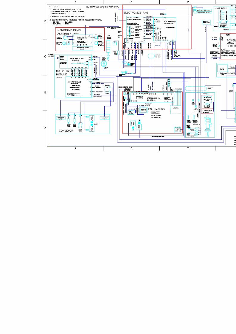
8/16/2019 Dispensig c 740 nordson
http://slidepdf.com/reader/full/dispensig-c-740-nordson 209/240

8/16/2019 Dispensig c 740 nordson
http://slidepdf.com/reader/full/dispensig-c-740-nordson 210/240
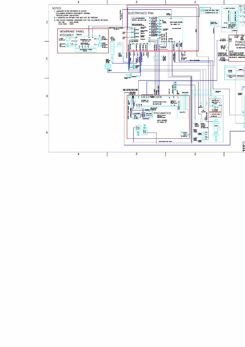
8/16/2019 Dispensig c 740 nordson
http://slidepdf.com/reader/full/dispensig-c-740-nordson 211/240

8/16/2019 Dispensig c 740 nordson
http://slidepdf.com/reader/full/dispensig-c-740-nordson 212/240
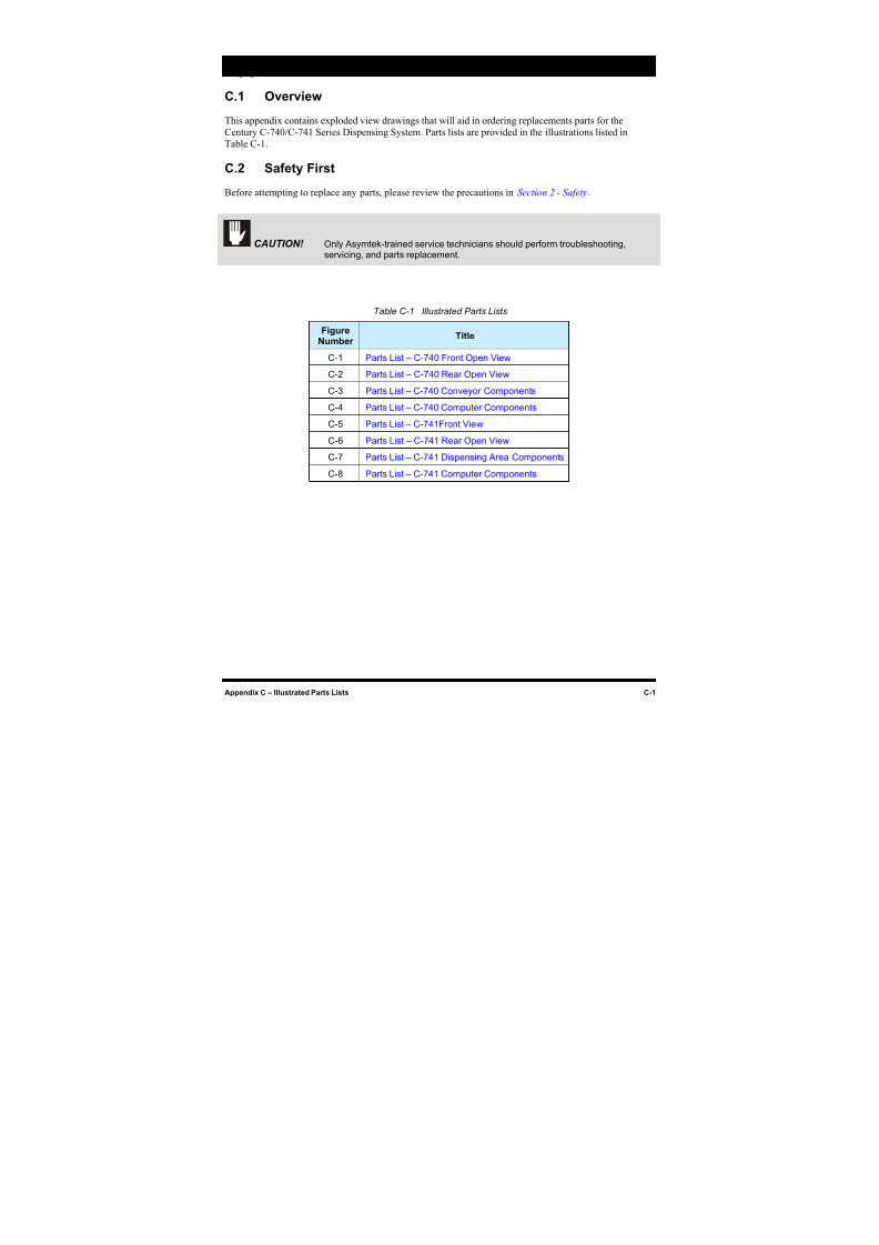
8/16/2019 Dispensig c 740 nordson
http://slidepdf.com/reader/full/dispensig-c-740-nordson 213/240
Appendix C – Illustrated Parts Lists C-1
Appendix C - Illustrated Parts Lists
C.1 Overview
This appendix contains exploded view drawings that will aid in ordering replacements parts for the
Century C-740/C-741 Series Dispensing System. Parts lists are provided in the illustrations listed in
Table C-1.
C.2 Safety First
Before attempting to replace any parts, please review the precautions in Section 2 - Safety.
CAUTION! Only Asymtek-trained service technicians should perform troubleshooting,servicing, and parts replacement.
Table C-1 Illustrated Parts Lists
FigureNumber
Title
C-1 Parts List – C-740 Front Open View
C-2 Parts List – C-740 Rear Open View
C-3 Parts List – C-740 Conveyor Components
C-4 Parts List – C-740 Computer Components
C-5 Parts List – C-741Front View
C-6 Parts List – C-741 Rear Open View
C-7 Parts List – C-741 Dispensing Area Components
C-8 Parts List – C-741 Computer Components
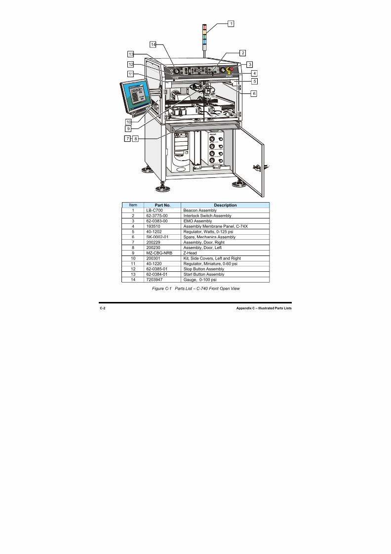
8/16/2019 Dispensig c 740 nordson
http://slidepdf.com/reader/full/dispensig-c-740-nordson 214/240
C-2 Appendix C – Illustrated Parts Lists
Item Part No. Description
1 LB-C700 Beacon Assembly
2 62-3775-00 Interlock Switch Assembly
3 62-0383-00 EMO Assembly
4 193510 Assembly Membrane Panel, C-74X
5 40-1202 Regulator, Watts, 0-125 psi
6 SK-0002-01 Spare, Mechanics Assembly
7 200229 Assembly, Door, Right
8 200230 Assembly, Door, Left
9 MZ-CBG-NRB Z-Head
10 200301 Kit, Side Covers, Left and Right
11 40-1220 Regulator, Miniature, 0-60 psi
12 62-0385-01 Stop Button Assembly
13 62-0384-01 Start Button Assembly
14 7203947 Gauge, 0-100 psi
Figure C-1 Parts List – C-740 Front Open View
1
2
3
4
5
6
9
11
10
12
13
14
87
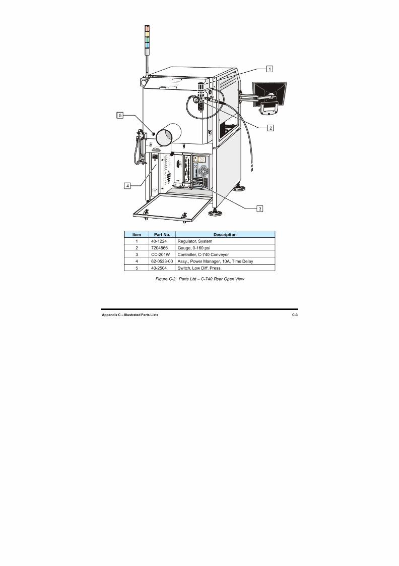
8/16/2019 Dispensig c 740 nordson
http://slidepdf.com/reader/full/dispensig-c-740-nordson 215/240
Appendix C – Illustrated Parts Lists C-3
Item Part No. Description
1 40-1224 Regulator, System
2 7204866 Gauge, 0-160 psi
3 CC-201W Controller, C-740 Conveyor4 62-0533-00 Assy., Power Manager, 10A, Time Delay
5 40-2504 Switch, Low Diff. Press.
Figure C-2 Parts List – C-740 Rear Open View
1
2
3
4
5
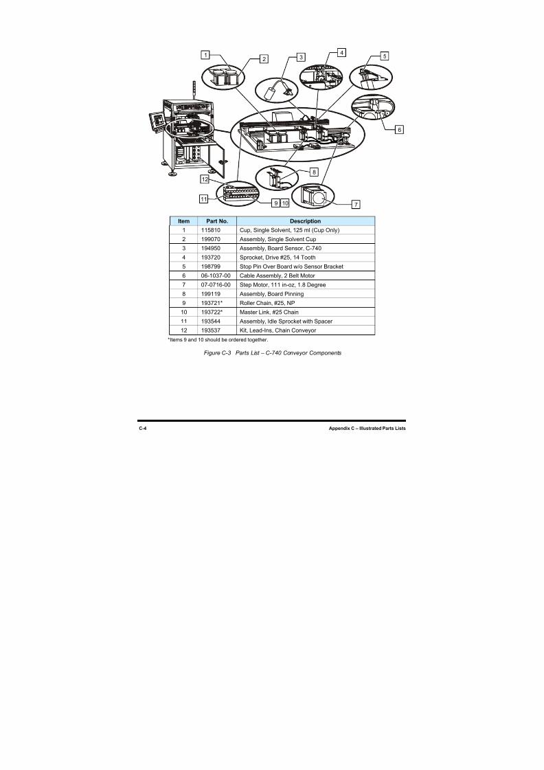
8/16/2019 Dispensig c 740 nordson
http://slidepdf.com/reader/full/dispensig-c-740-nordson 216/240
C-4 Appendix C – Illustrated Parts Lists
Item Part No. Description
1 115810 Cup, Single Solvent, 125 ml (Cup Only)
2 199070 Assembly, Single Solvent Cup
3 194950 Assembly, Board Sensor, C-740
4 193720 Sprocket, Drive #25, 14 Tooth
5 198799 Stop Pin Over Board w/o Sensor Bracket
6 06-1037-00 Cable Assembly, 2 Belt Motor
7 07-0716-00 Step Motor, 111 in-oz, 1.8 Degree
8 199119 Assembly, Board Pinning
9 193721* Roller Chain, #25, NP
10 193722* Master Link, #25 Chain
11 193544 Assembly, Idle Sprocket with Spacer
12 193537 Kit, Lead-Ins, Chain Conveyor
*Items 9 and 10 should be ordered together.
Figure C-3 Parts List – C-740 Conveyor Components
10
12 3
45
8
911
12
6
7
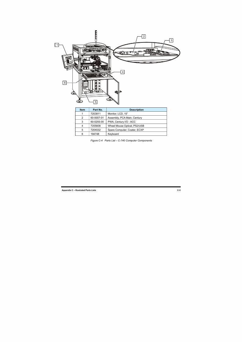
8/16/2019 Dispensig c 740 nordson
http://slidepdf.com/reader/full/dispensig-c-740-nordson 217/240
Appendix C – Illustrated Parts Lists C-5
Item Part No. Description
1 7203811 Monitor, LCD, 15”
2 60-0007-01 Assembly, PCA Main, Century
3 60-0255-00 PWA, Century I/O - ACC
4 7205608 Wheel Mouse Optical, PS2/USB
5 7204032 Spare Computer, Coater, ECXP
6 194748 Keyboard
Figure C-4 Parts List – C-740 Computer Components
1
2
3
4
6
5
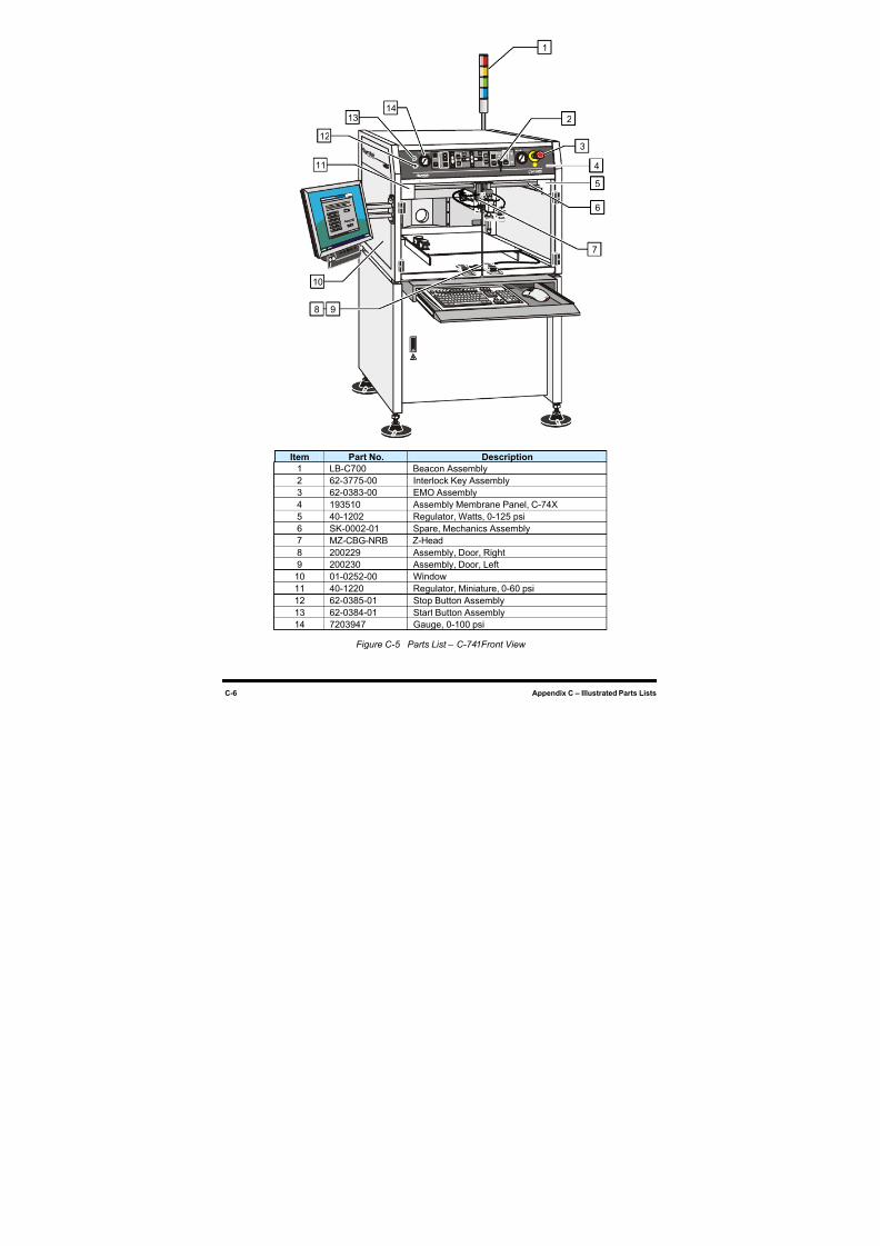
8/16/2019 Dispensig c 740 nordson
http://slidepdf.com/reader/full/dispensig-c-740-nordson 218/240
C-6 Appendix C – Illustrated Parts Lists
Item Part No. Description
1 LB-C700 Beacon Assembly
2 62-3775-00 Interlock Key Assembly
3 62-0383-00 EMO Assembly
4 193510 Assembly Membrane Panel, C-74X
5 40-1202 Regulator, Watts, 0-125 psi
6 SK-0002-01 Spare, Mechanics Assembly
7 MZ-CBG-NRB Z-Head
8 200229 Assembly, Door, Right
9 200230 Assembly, Door, Left10 01-0252-00 Window
11 40-1220 Regulator, Miniature, 0-60 psi
12 62-0385-01 Stop Button Assembly
13 62-0384-01 Start Button Assembly
14 7203947 Gauge, 0-100 psi
Figure C-5 Parts List – C-741Front View
1
3
4
5
6
7
11
10
12
1314
6
8 9
2
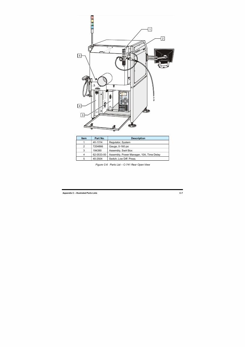
8/16/2019 Dispensig c 740 nordson
http://slidepdf.com/reader/full/dispensig-c-740-nordson 219/240
Appendix C – Illustrated Parts Lists C-7
Item Part No. Description
1 40-1224 Regulator, System
2 7204866 Gauge, 0-160 psi
3 194390 Assembly, Swirl Box
4 62-0533-00 Assembly, Power Manager, 10A, Time Delay
5 40-2504 Switch, Low Diff. Press.
Figure C-6 Parts List – C-741 Rear Open View
1
2
3
4
5
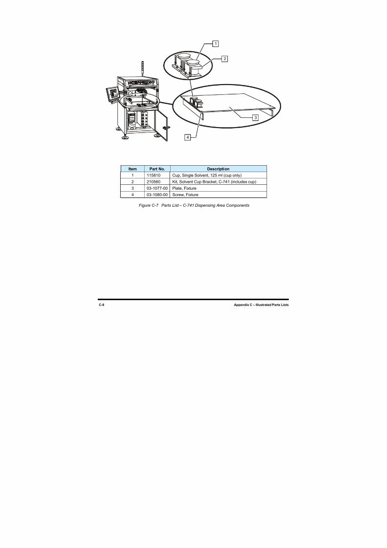
8/16/2019 Dispensig c 740 nordson
http://slidepdf.com/reader/full/dispensig-c-740-nordson 220/240
C-8 Appendix C – Illustrated Parts Lists
Item Part No. Description
1 115810 Cup, Single Solvent, 125 ml (cup only)
2 210560 Kit, Solvent Cup Bracket, C-741 (includes cup)
3 03-1077-00 Plate, Fixture
4 03-1080-00 Screw, Fixture
Figure C-7 Parts List – C-741 Dispensing Area Components
1
2
4
3
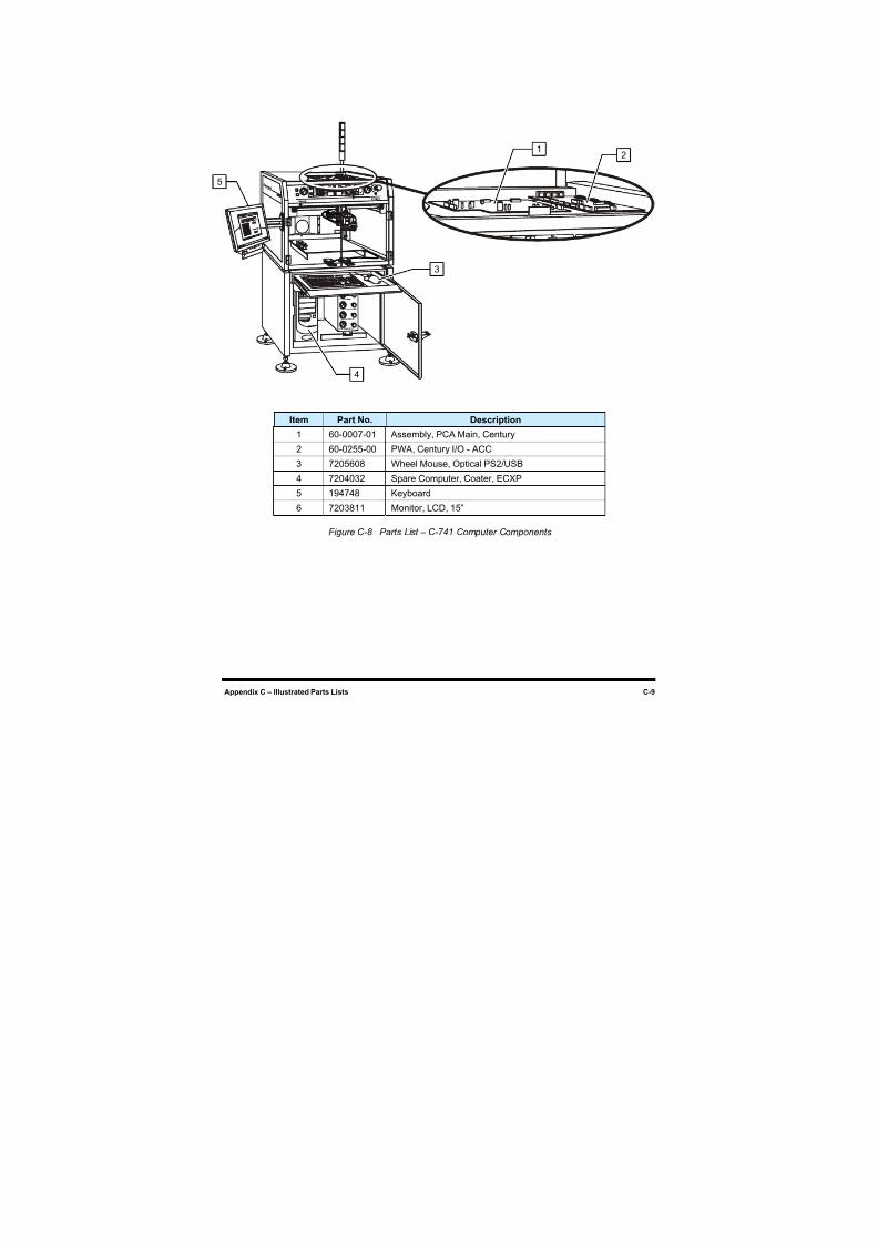
8/16/2019 Dispensig c 740 nordson
http://slidepdf.com/reader/full/dispensig-c-740-nordson 221/240
Appendix C – Illustrated Parts Lists C-9
Item Part No. Description1 60-0007-01 Assembly, PCA Main, Century
2 60-0255-00 PWA, Century I/O - ACC
3 7205608 Wheel Mouse, Optical PS2/USB
4 7204032 Spare Computer, Coater, ECXP
5 194748 Keyboard
6 7203811 Monitor, LCD, 15”
Figure C-8 Parts List – C-741 Computer Components
12
3
4
5

8/16/2019 Dispensig c 740 nordson
http://slidepdf.com/reader/full/dispensig-c-740-nordson 222/240
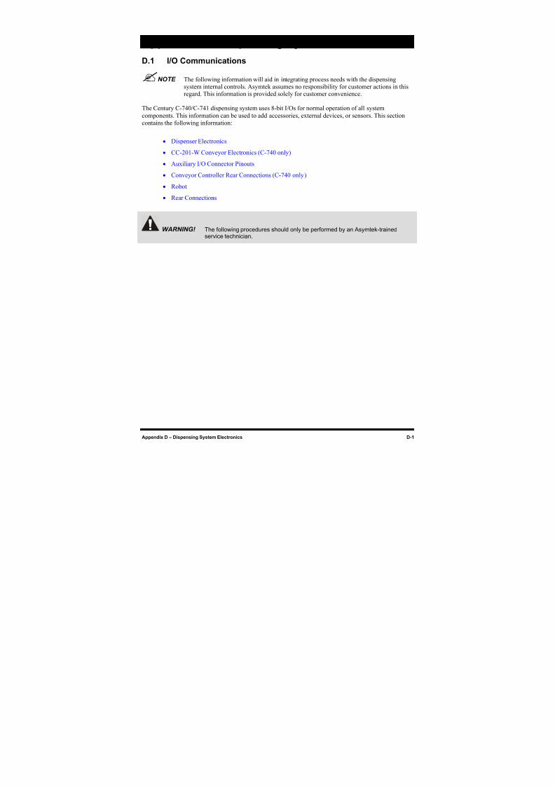
8/16/2019 Dispensig c 740 nordson
http://slidepdf.com/reader/full/dispensig-c-740-nordson 223/240
Appendix D – Dispensing System Electronics D-1
Appendix D - Dispensing System Electronics
D.1 I/O Communications
NOTE The following information will aid in integrating process needs with the dispensing
system internal controls. Asymtek assumes no responsibility for customer actions in thisregard. This information is provided solely for customer convenience.
The Century C-740/C-741 dispensing system uses 8-bit I/Os for normal operation of all system
components. This information can be used to add accessories, external devices, or sensors. This section
contains the following information:
• Dispenser Electronics
• CC-201-W Conveyor Electronics (C-740 only)
• Auxiliary I/O Connector Pinouts
•
Conveyor Controller Rear Connections (C-740 only)• Robot
• Rear Connections
WARNING! The following procedures should only be performed by an Asymtek-trainedservice technician.
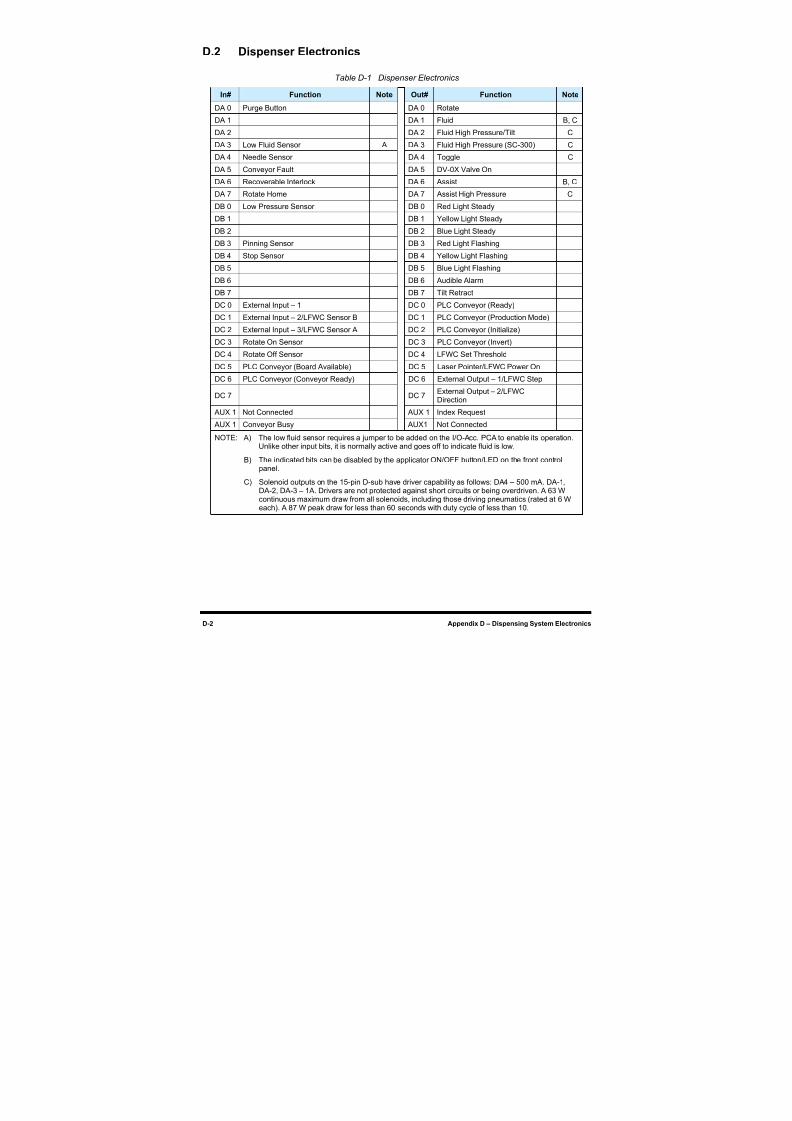
8/16/2019 Dispensig c 740 nordson
http://slidepdf.com/reader/full/dispensig-c-740-nordson 224/240
D-2 Appendix D – Dispensing System Electronics
D.2 Dispenser Electronics
Table D-1 Dispenser Electronics
In# Function Note Out# Function Note
DA 0 Purge Button DA 0 Rotate
DA 1 DA 1 Fluid B, C
DA 2 DA 2 Fluid High Pressure/Tilt C
DA 3 Low Fluid Sensor A DA 3 Fluid High Pressure (SC-300) C
DA 4 Needle Sensor DA 4 Toggle C
DA 5 Conveyor Fault DA 5 DV-0X Valve On
DA 6 Recoverable Interlock DA 6 Assist B, C
DA 7 Rotate Home DA 7 Assist High Pressure C
DB 0 Low Pressure Sensor DB 0 Red Light Steady
DB 1 DB 1 Yellow Light Steady
DB 2 DB 2 Blue Light Steady
DB 3 Pinning Sensor DB 3 Red Light Flashing
DB 4 Stop Sensor DB 4 Yellow Light Flashing
DB 5 DB 5 Blue Light Flashing
DB 6 DB 6 Audible Alarm
DB 7 DB 7 Tilt Retract
DC 0 External Input – 1 DC 0 PLC Conveyor (Ready)
DC 1 External Input – 2/LFWC Sensor B DC 1 PLC Conveyor (Production Mode)
DC 2 External Input – 3/LFWC Sensor A DC 2 PLC Conveyor (Initialize)
DC 3 Rotate On Sensor DC 3 PLC Conveyor (Invert)
DC 4 Rotate Off Sensor DC 4 LFWC Set Threshold
DC 5 PLC Conveyor (Board Available) DC 5 Laser Pointer/LFWC Power On
DC 6 PLC Conveyor (Conveyor Ready) DC 6 External Output – 1/LFWC Step
DC 7 DC 7External Output – 2/LFWCDirection
AUX 1 Not Connected AUX 1 Index Request
AUX 1 Conveyor Busy AUX1 Not Connected
NOTE: A) The low fluid sensor requires a jumper to be added on the I/O-Acc. PCA to enable its operation.Unlike other input bits, it is normally active and goes off to indicate fluid is low.
B) The indicated bits can be disabled by the applicator ON/OFF button/LED on the front controlpanel.
C) Solenoid outputs on the 15-pin D-sub have driver capability as follows: DA4 – 500 mA. DA-1,DA-2, DA-3 – 1A. Drivers are not protected against short circuits or being overdriven. A 63 Wcontinuous maximum draw from all solenoids, including those driving pneumatics (rated at 6 W
each). A 87 W peak draw for less than 60 seconds with duty cycle of less than 10.
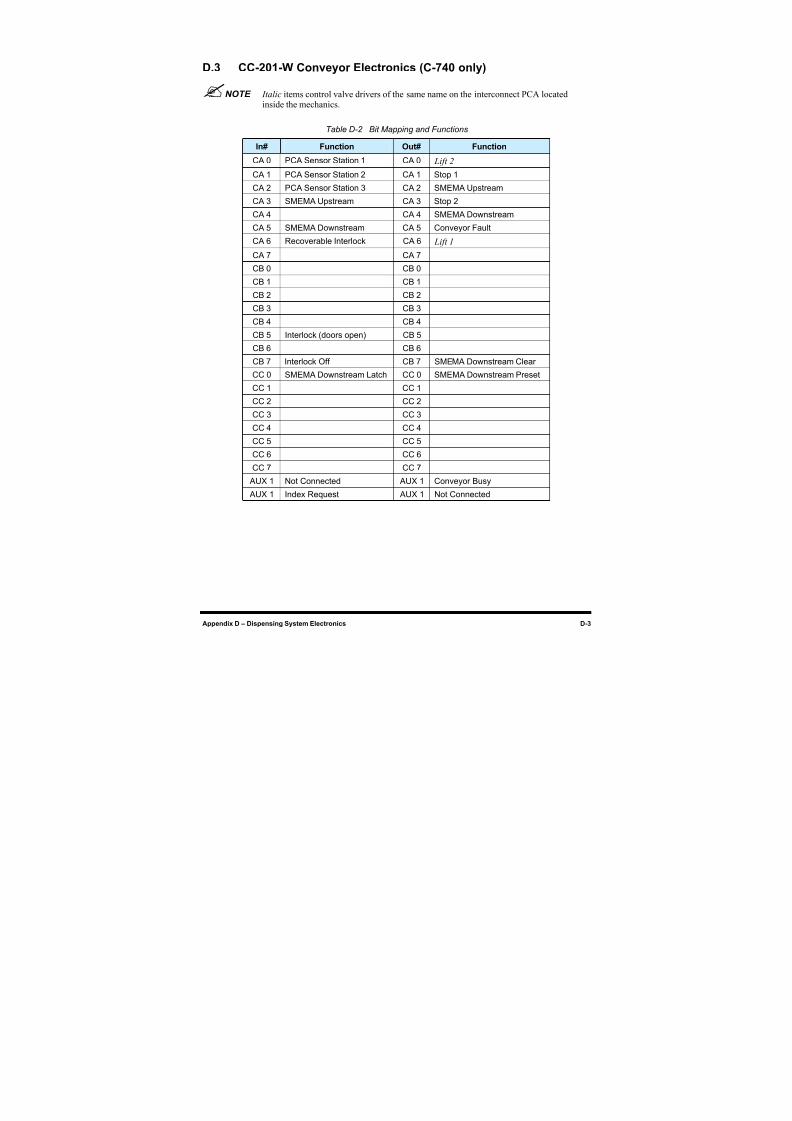
8/16/2019 Dispensig c 740 nordson
http://slidepdf.com/reader/full/dispensig-c-740-nordson 225/240
Appendix D – Dispensing System Electronics D-3
D.3 CC-201-W Conveyor Electronics (C-740 only)
NOTE Italic items control valve drivers of the same name on the interconnect PCA locatedinside the mechanics.
Table D-2 Bit Mapping and Functions
In# Function Out# Function
CA 0 PCA Sensor Station 1 CA 0 Lift 2
CA 1 PCA Sensor Station 2 CA 1 Stop 1
CA 2 PCA Sensor Station 3 CA 2 SMEMA Upstream
CA 3 SMEMA Upstream CA 3 Stop 2
CA 4 CA 4 SMEMA Downstream
CA 5 SMEMA Downstream CA 5 Conveyor Fault
CA 6 Recoverable Interlock CA 6 Lift 1
CA 7 CA 7
CB 0 CB 0
CB 1 CB 1
CB 2 CB 2
CB 3 CB 3
CB 4 CB 4
CB 5 Interlock (doors open) CB 5
CB 6 CB 6
CB 7 Interlock Off CB 7 SMEMA Downstream Clear
CC 0 SMEMA Downstream Latch CC 0 SMEMA Downstream Preset
CC 1 CC 1
CC 2 CC 2
CC 3 CC 3
CC 4 CC 4
CC 5 CC 5
CC 6 CC 6
CC 7 CC 7
AUX 1 Not Connected AUX 1 Conveyor Busy
AUX 1 Index Request AUX 1 Not Connected
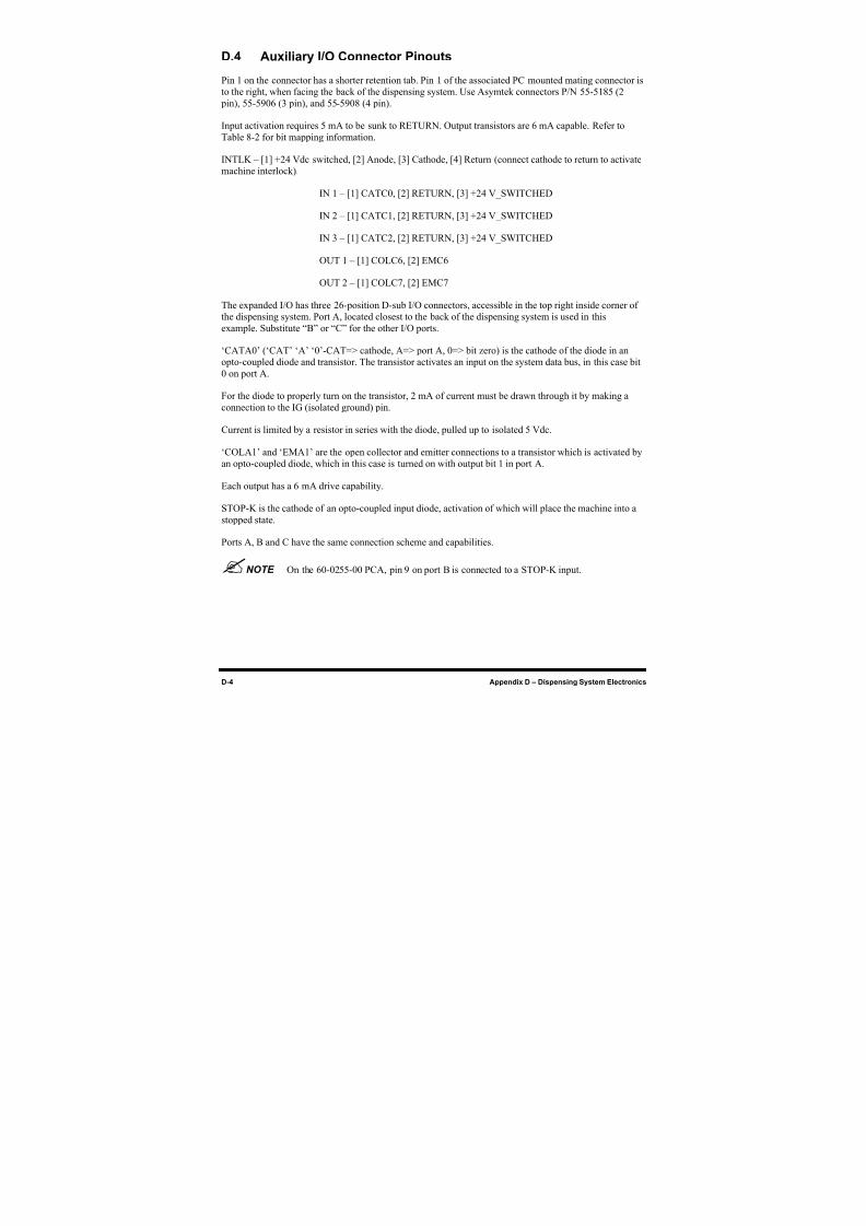
8/16/2019 Dispensig c 740 nordson
http://slidepdf.com/reader/full/dispensig-c-740-nordson 226/240
D-4 Appendix D – Dispensing System Electronics
D.4 Auxiliary I/O Connector Pinouts
Pin 1 on the connector has a shorter retention tab. Pin 1 of the associated PC mounted mating connector is
to the right, when facing the back of the dispensing system. Use Asymtek connectors P/N 55-5185 (2
pin), 55-5906 (3 pin), and 55-5908 (4 pin).
Input activation requires 5 mA to be sunk to RETURN. Output transistors are 6 mA capable. Refer to
Table 8-2 for bit mapping information.
INTLK – [1] +24 Vdc switched, [2] Anode, [3] Cathode, [4] Return (connect cathode to return to activate
machine interlock).
IN 1 – [1] CATC0, [2] RETURN, [3] +24 V_SWITCHED
IN 2 – [1] CATC1, [2] RETURN, [3] +24 V_SWITCHED
IN 3 – [1] CATC2, [2] RETURN, [3] +24 V_SWITCHED
OUT 1 – [1] COLC6, [2] EMC6
OUT 2 – [1] COLC7, [2] EMC7
The expanded I/O has three 26-position D-sub I/O connectors, accessible in the top right inside corner of
the dispensing system. Port A, located closest to the back of the dispensing system is used in this
example. Substitute “B” or “C” for the other I/O ports.
‘CATA0’ (‘CAT’ ‘A’ ‘0’-CAT=> cathode, A=> port A, 0=> bit zero) is the cathode of the diode in an
opto-coupled diode and transistor. The transistor activates an input on the system data bus, in this case bit
0 on port A.
For the diode to properly turn on the transistor, 2 mA of current must be drawn through it by making a
connection to the IG (isolated ground) pin.
Current is limited by a resistor in series with the diode, pulled up to isolated 5 Vdc.
‘COLA1’ and ‘EMA1’ are the open collector and emitter connections to a transistor which is activated by
an opto-coupled diode, which in this case is turned on with output bit 1 in port A.
Each output has a 6 mA drive capability.
STOP-K is the cathode of an opto-coupled input diode, activation of which will place the machine into a
stopped state.
Ports A, B and C have the same connection scheme and capabilities.
NOTE On the 60-0255-00 PCA, pin 9 on port B is connected to a STOP-K input.
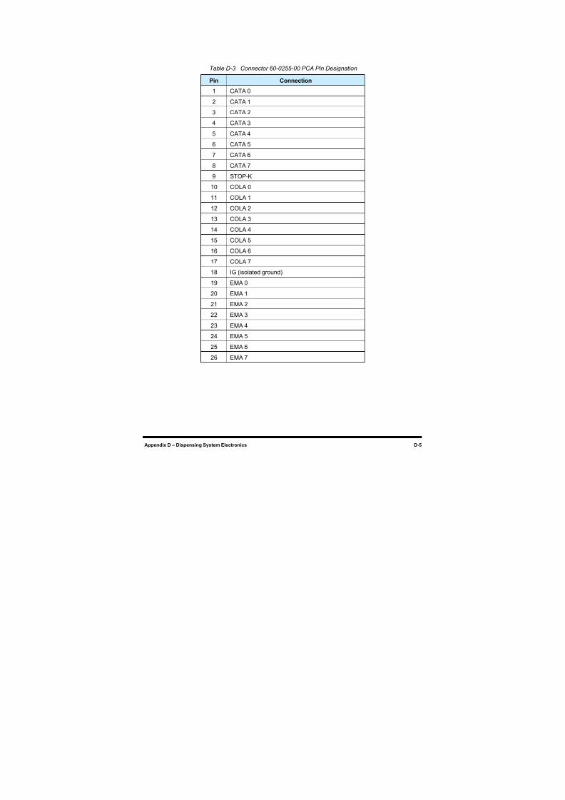
8/16/2019 Dispensig c 740 nordson
http://slidepdf.com/reader/full/dispensig-c-740-nordson 227/240
8/16/2019 Dispensig c 740 nordson
http://slidepdf.com/reader/full/dispensig-c-740-nordson 228/240
D-6 Appendix D – Dispensing System Electronics
D.5 Conveyor Controller Rear Connections (C-740 only)
16H
Figure D-1 shows the Conveyor Controller on its side to make it easier to read the connections. The
Conveyor Controller stands upright in the bottom of the Century C-740 dispensing system.
NOTE The controller is not customer serviceable.
Table D-4 Conveyor Controller Rear Connections
Item Feature Description
1 FUSE Fuse holder for 0.125 A 250 V fuse
2 X-AXIS 13-pin D-shell connector, conveyor,X-axis movement control left and right
3 UPSTREAM 11-pin D-shell connector for upstream communication SMEMA cable
4 DOWNSTREAM 11-pin D-shell connector for downstream communication SMEMA cable
5 SENSOR 11-pin D-shell connector for board sensor
6 INTERFACE COM 1, 21-pin RS232 interface connector 201D
7 POWER INPUTMODULE
Power input cable connector and fuse holder
8 Z-AXIS 13-pin D-shell connector, Z-head up and down movement control
9 DIP SWITCHES 8-position baud rate DIP switch, position 7 turned off
10 RS232C COM 2, 21-pin RS232 interface connector 201 W
11 Y-AXIS 13-pin D-shell connector, conveyor,Y-axis movement control backwardand forward—not used on C-740
Figure D-1 Conveyor Controller Rear Connections
1
11 10 9 8
2 3 4 5 6 7
8/16/2019 Dispensig c 740 nordson
http://slidepdf.com/reader/full/dispensig-c-740-nordson 229/240
Appendix D – Dispensing System Electronics D-7
D.6 Robot
NOTE The Robot is not customer serviceable. The Robot is factory calibrated. Do not try torepair or calibrate the Robot.
The Robot can perform motion on five different levels:
• X-axis
• Y-axis
• Z-axis
• Rotate
• Tilt
Solenoid valves used to trigger the Fluid Dispensing Applicator are located inside the work area. X, Y,
and Z motor and solenoid control cables are supplied with the system. Cables are shielded for insulation
from external noise sources. The cables connect to the back of the Robot Controller.
D.7 Robot Main Board
The Robot main integrated circuit board is accessible by removing the top panel of the dispensing system.
NOTE The Robot Controller is not customer serviceable.
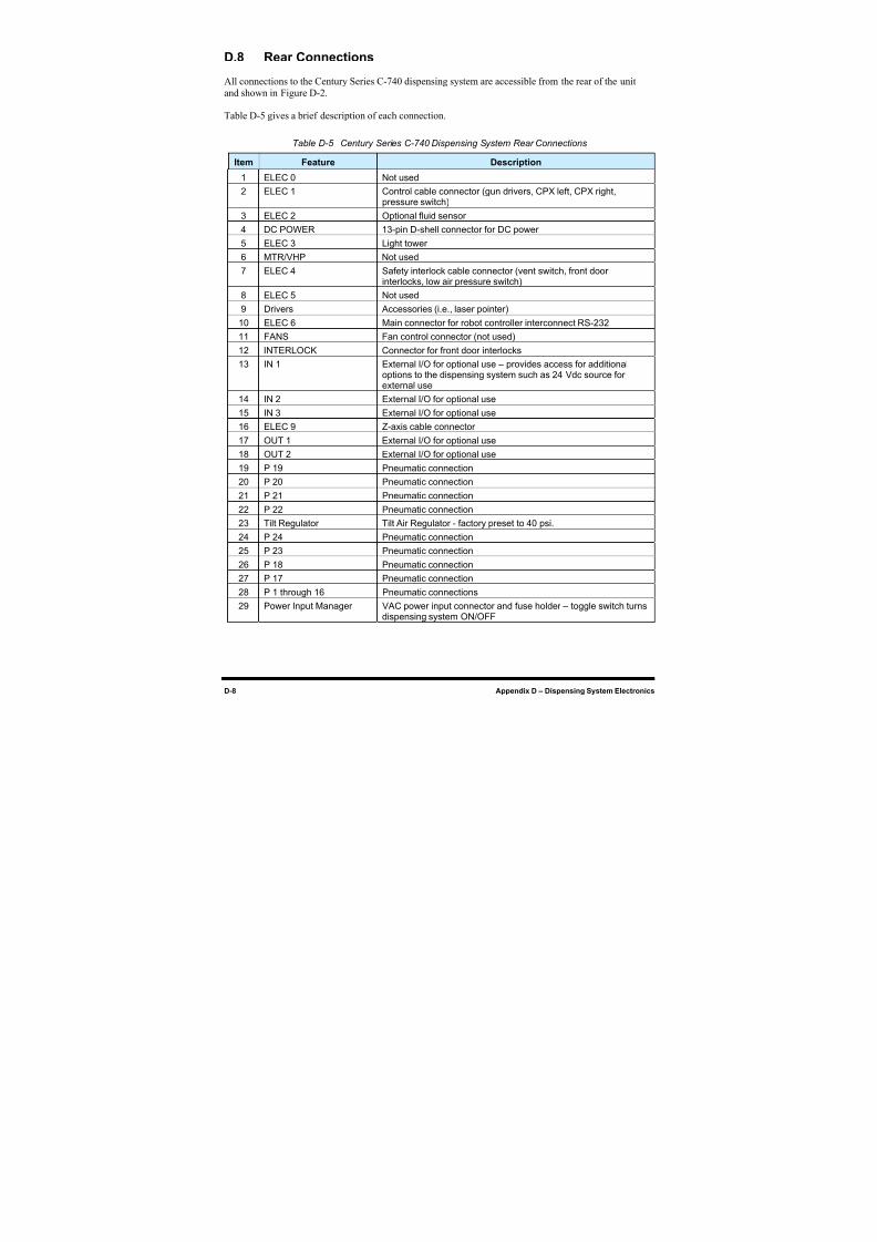
8/16/2019 Dispensig c 740 nordson
http://slidepdf.com/reader/full/dispensig-c-740-nordson 230/240
D-8 Appendix D – Dispensing System Electronics
D.8 Rear Connections
All connections to the Century Series C-740 dispensing system are accessible from the rear of the unit
and shown in17H
Figure D-2.
18H
Table D-5 gives a brief description of each connection.
Table D-5 Century Series C-740 Dispensing System Rear Connections
Item Feature Description
1 ELEC 0 Not used
2 ELEC 1 Control cable connector (gun drivers, CPX left, CPX right,pressure switch)
3 ELEC 2 Optional fluid sensor
4 DC POWER 13-pin D-shell connector for DC power
5 ELEC 3 Light tower
6 MTR/VHP Not used
7 ELEC 4 Safety interlock cable connector (vent switch, front door
interlocks, low air pressure switch)8 ELEC 5 Not used
9 Drivers Accessories (i.e., laser pointer)
10 ELEC 6 Main connector for robot controller interconnect RS-232
11 FANS Fan control connector (not used)
12 INTERLOCK Connector for front door interlocks
13 IN 1 External I/O for optional use – provides access for additionaloptions to the dispensing system such as 24 Vdc source forexternal use
14 IN 2 External I/O for optional use
15 IN 3 External I/O for optional use
16 ELEC 9 Z-axis cable connector
17 OUT 1 External I/O for optional use
18 OUT 2 External I/O for optional use
19 P 19 Pneumatic connection
20 P 20 Pneumatic connection
21 P 21 Pneumatic connection
22 P 22 Pneumatic connection
23 Tilt Regulator Tilt Air Regulator - factory preset to 40 psi.
24 P 24 Pneumatic connection
25 P 23 Pneumatic connection
26 P 18 Pneumatic connection
27 P 17 Pneumatic connection
28 P 1 through 16 Pneumatic connections
29 Power Input Manager VAC power input connector and fuse holder – toggle switch turnsdispensing system ON/OFF
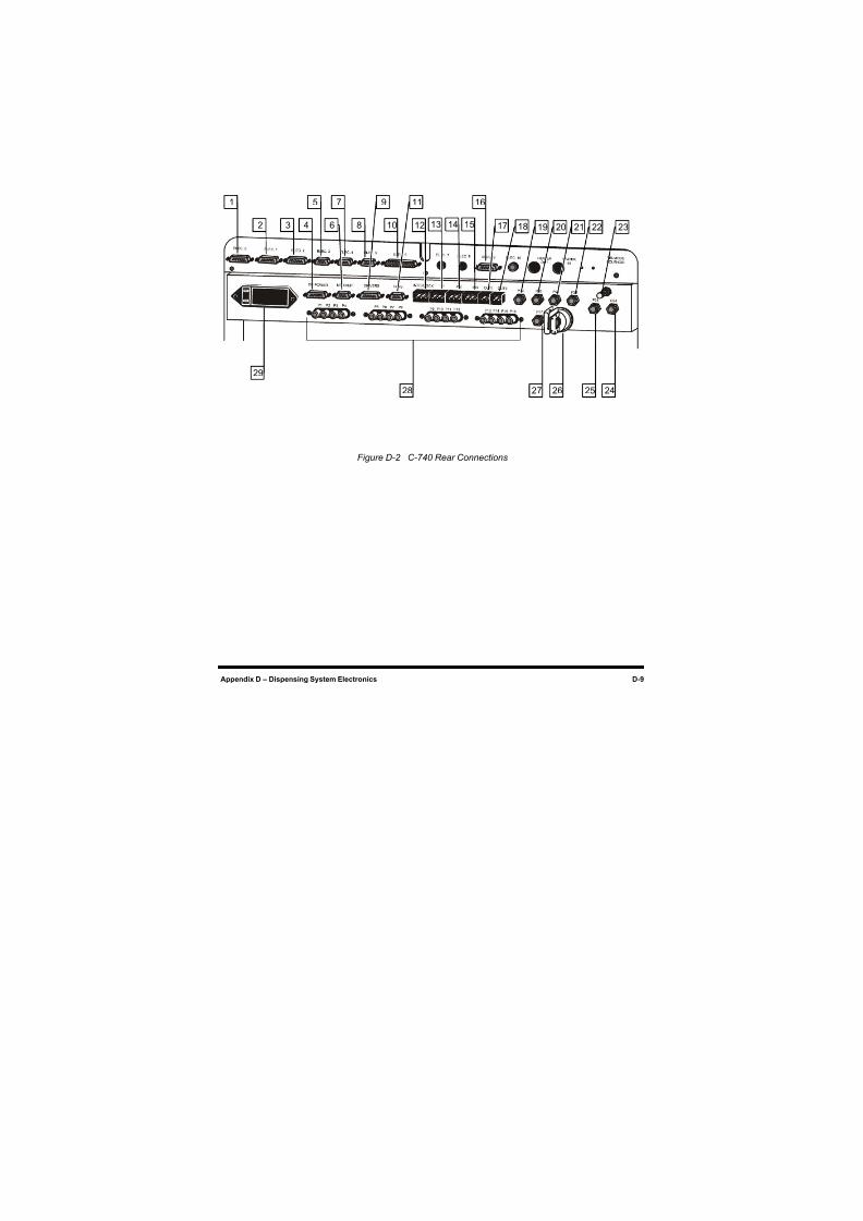
8/16/2019 Dispensig c 740 nordson
http://slidepdf.com/reader/full/dispensig-c-740-nordson 231/240
Appendix D – Dispensing System Electronics D-9
Figure D-2 C-740 Rear Connections
1 5 7 16
18 19 20
29
27 26 25 2428
9 11
2 3 8 104 6 12 13 14 15 17 21 22 23

8/16/2019 Dispensig c 740 nordson
http://slidepdf.com/reader/full/dispensig-c-740-nordson 232/240
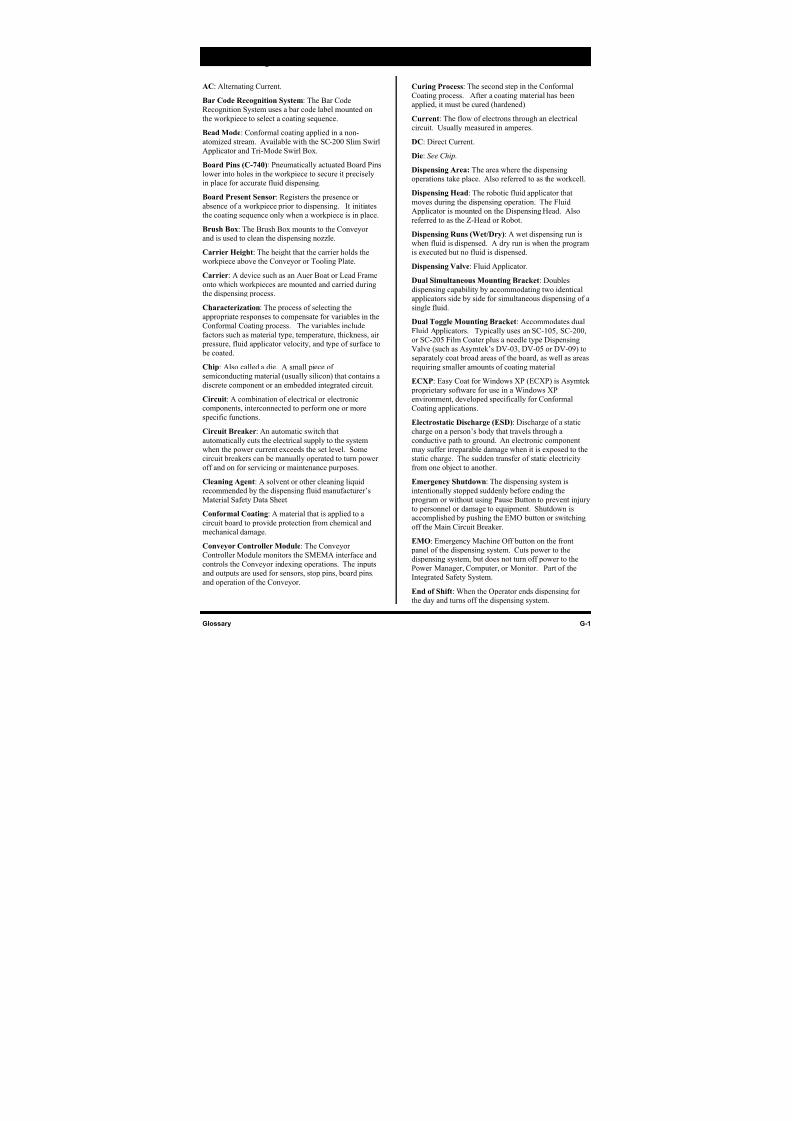
8/16/2019 Dispensig c 740 nordson
http://slidepdf.com/reader/full/dispensig-c-740-nordson 233/240
Glossary G-1
Glossary
AC: Alternating Current.
Bar Code Recognition System: The Bar Code
Recognition System uses a bar code label mounted on
the workpiece to select a coating sequence.
Bead Mode: Conformal coating applied in a non-
atomized stream. Available with the SC-200 Slim Swirl
Applicator and Tri-Mode Swirl Box.
Board Pins (C-740): Pneumatically actuated Board Pins
lower into holes in the workpiece to secure it precisely
in place for accurate fluid dispensing.
Board Present Sensor: Registers the presence or
absence of a workpiece prior to dispensing. It initiates
the coating sequence only when a workpiece is in place.
Brush Box: The Brush Box mounts to the Conveyor
and is used to clean the dispensing nozzle.
Carrier Height: The height that the carrier holds theworkpiece above the Conveyor or Tooling Plate.
Carrier: A device such as an Auer Boat or Lead Frame
onto which workpieces are mounted and carried during
the dispensing process.
Characterization: The process of selecting the
appropriate responses to compensate for variables in the
Conformal Coating process. The variables include
factors such as material type, temperature, thickness, air
pressure, fluid applicator velocity, and type of surface to
be coated.
Chip: Also called a die. A small piece of
semiconducting material (usually silicon) that contains a
discrete component or an embedded integrated circuit.
Circuit: A combination of electrical or electronic
components, interconnected to perform one or more
specific functions.
Circuit Breaker: An automatic switch that
automatically cuts the electrical supply to the system
when the power current exceeds the set level. Some
circuit breakers can be manually operated to turn power
off and on for servicing or maintenance purposes.
Cleaning Agent: A solvent or other cleaning liquid
recommended by the dispensing fluid manufacturer’s
Material Safety Data Sheet.
Conformal Coating: A material that is applied to a
circuit board to provide protection from chemical and
mechanical damage.
Conveyor Controller Module: The Conveyor
Controller Module monitors the SMEMA interface and
controls the Conveyor indexing operations. The inputs
and outputs are used for sensors, stop pins, board pins,
and operation of the Conveyor.
Curing Process: The second step in the Conformal
Coating process. After a coating material has been
applied, it must be cured (hardened).
Current: The flow of electrons through an electrical
circuit. Usually measured in amperes.
DC: Direct Current.
Die: See Chip.
Dispensing Area: The area where the dispensing
operations take place. Also referred to as the workcell.
Dispensing Head: The robotic fluid applicator that
moves during the dispensing operation. The Fluid
Applicator is mounted on the Dispensing Head. Also
referred to as the Z-Head or Robot.
Dispensing Runs (Wet/Dry): A wet dispensing run is
when fluid is dispensed. A dry run is when the program
is executed but no fluid is dispensed.
Dispensing Valve: Fluid Applicator .
Dual Simultaneous Mounting Bracket: Doubles
dispensing capability by accommodating two identical
applicators side by side for simultaneous dispensing of a
single fluid.
Dual Toggle Mounting Bracket: Accommodates dual
Fluid Applicators. Typically uses an SC-105, SC-200,
or SC-205 Film Coater plus a needle type Dispensing
Valve (such as Asymtek’s DV-03, DV-05 or DV-09) to
separately coat broad areas of the board, as well as areas
requiring smaller amounts of coating material
ECXP: Easy Coat for Windows XP (ECXP) is Asymtek proprietary software for use in a Windows XP
environment, developed specifically for Conformal
Coating applications.
Electrostatic Discharge (ESD): Discharge of a static
charge on a person’s body that travels through a
conductive path to ground. An electronic component
may suffer irreparable damage when it is exposed to the
static charge. The sudden transfer of static electricity
from one object to another.
Emergency Shutdown: The dispensing system is
intentionally stopped suddenly before ending the
program or without using Pause Button to prevent injury
to personnel or damage to equipment. Shutdown isaccomplished by pushing the EMO button or switching
off the Main Circuit Breaker.
EMO: Emergency Machine Off button on the front
panel of the dispensing system. Cuts power to the
dispensing system, but does not turn off power to the
Power Manager, Computer, or Monitor. Part of the
Integrated Safety System.
End of Shift: When the Operator ends dispensing for
the day and turns off the dispensing system.
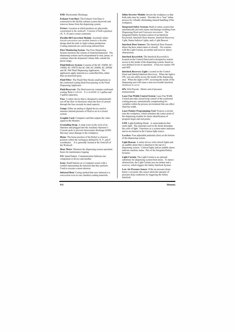
8/16/2019 Dispensig c 740 nordson
http://slidepdf.com/reader/full/dispensig-c-740-nordson 234/240
G-2 Glossary
ESD: Electrostatic Discharge.
Exhaust Vent Duct: The Exhaust Vent Duct is
connected to the facility exhaust system ductwork and
removes fumes from the dispensing system.
Fixture: Location at which products are physically
constrained in the workcell. Consists of both a position
(X, Y, Z) and a corner constraint.
Flexible IR/Convection Module: Asymtek's inlineforced-convection cure module features a flexible
design ideal for mid- to high-volume production.
Coating materials are cured using infrared heat.
Flow Monitoring System: The Flow Monitoring
System monitors the volume of material dispensed. The
dispensing system can be programmed to stop, pause, or
continue when the dispensed volume falls outside the
preset range.
Fluid Delivery System: Consists of the SC-104HS, SC-
105HS, SC-10XVCSm SC-200, SC-204HS, SC-205HS
and SC-300 Fluid Dispensing Applicators. The
applicators apply material as a controlled film, rather
than an atomized spray.
Fluid Filter: The Fluid Filter blocks small particles in
the conformal coating fluid from passing to the Fluid
Dispensing Applicator.
Fluid Reservoir: The fluid reservoir contains conformal
coating fluid or solvent. It is available in 1-gallon and
5-gallon capacities.
Fuse: A safety device that is designed to automatically
cut off the flow of electricity when the flow of current
through the fuse exceeds its rated capacity.
Gauge: Either an analog or digital device used to
measure internal pressure of fluid or air in a closed
system.
Graphic Card: Computer card that outputs the video
signal to the Monitor.
Grounding Strap: A strap worn on the wrist of an
Operator and plugged into the Auxiliary Operator’s
Console jacks to prevent electrostatic discharge (ESD)
that may cause damage to the workpiece.
Home: The home position of the Robot is a known
position within the workspace defined by X, Y, and Z
coordinates. It is generally located at the front left of
the Workcell.
Hour Meter: Monitors the dispensing system operationhours for maintenance logging.
I/O: Input/Output. Communication between one
component or device and another.
Icons: Small buttons on a Computer screen with a
symbol representing the function that they perform.
Used to execute a menu shortcut.
Infrared Heat: Curing method that uses infrared or a
convection oven to cure (harden) coating materials.
Inline Inverter Module: Inverts the workpiece so that
both sides may be coated. Provides for a “true” inline
process by virtually eliminating manual handling of the
workpiece.
Integrated Safety Systems: Built-in safety system that
automatically prevents injury and damage resulting from
Dispensing Head and Conveyor movement. The
Integrated Safety Systems consist of an Interlock
Keyswitch, Interlock Door Sensors, Interlock RecoveryLight, Status Indictor Lights, and a Light Beacon.
Interlock Door Sensors: The Interlock Door Sensors
detect the door status (open or closed). On systems
with the Light Curtain, an emitter and receiver detect
obstructions.
Interlock Keyswitch: The Interlock Keyswitch is
located on the Control Panel and is designed to restrict
access to the inside of the dispensing system, based on
user-defined levels of operation. It has two modes: ON
and OFF.
Interlock Recovery Light: Located on the Control
Panel and labeled Interlock Recovery. When the light isON, you can safely access the inside of the dispensing
area. When the light is OFF, accessing the inside of the
dispensing area will cause a non-recoverable interlock
shutdown to occur.
kPa: Kilo Pascals. Metric unit of pressure
measurement.
Laser Fan Width Control System: Laser Fan Width
Control provides closed-loop control of the conformal
coating process, automatically compensating for
variables within the process environment that can affect
fluid fan width.
Laser Pointer Programming Tool: Projects a red dot
onto the workpiece, which simulates the center point of
the dispensing module for faster identification of
program begin and end points.
LED: Light-Emitting-Diode. A semiconductor that
emits light. The materials used in the diode determine
the color of light. Functions as a system status indicator
and as an element in the Camera light source.
Levelers: Four adjustable pedestals (feet) on the bottom
of the dispensing system.
Light Beacon: A safety device with colored lights and
an audible alarm that is attached to the top of a
dispensing system. Colored lights and an audible alarm
indicate machine status. Part of the Integrated SafetySystems.
Light Curtain: The Light Curtain is an optional
substitute for dispensing system front doors. To detect
obstructions, the Light Curtain uses an emitter and a
receiver, which triggers the Safety Interlock System.
Low Air Pressure Sensor: If the air pressure drops
below a set point, this sensor alerts the operator of
pressure drop conditions by triggering the Safety
Interlock.
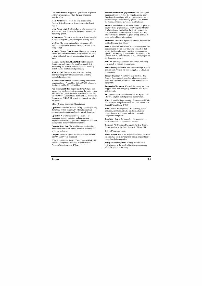
8/16/2019 Dispensig c 740 nordson
http://slidepdf.com/reader/full/dispensig-c-740-nordson 235/240
Glossary G-3
Low Fluid Sensor: Triggers a Light Beacon display or
software error message when the level of coating
material is low.
Main Air Inlet: The Main Air Inlet connects the
Century Series Dispensing System to your facility air
supply.
Main Power Inlet: The Main Power Inlet connects the
Main Power cable from the facility power source to thedispensing system.
Maintenance: Planned or unplanned activities intended
to keep the dispensing system in good working order.
Masking: The process of applying a temporary film,
tape, boot or plug that prevents the area covered from
being coated.
Material Change Over System: Allows you to switch
air and fluid lines between two reservoirs and the fluid
system without physically disconnecting fittings and
hoses.
Material Safety Data Sheet (MSDS): Information
sheet for the safe usage of a specific material. It is provided by the material manufacturer and is usually
included in the fluid material packaging.
Moisture (RTV) Cure: Cures (hardens) coating
materials using ambient conditions or a humidity-
controlled environment.
Monofilament Mode: Conformal coating applied in a
looping pattern. Available with the SC-200 Slim Swirl
Applicator and Tri-Mode Swirl Box.
Non-Recoverable Interlock Shutdown: When a non-
recoverable interlock shutdown occurs, the motor power
turns OFF, the system loses master references, and the
red “ABORT” System Status Indicator LED illuminates.
The program WILL NOT be able to resume from where
it stopped.
OEM: Original Equipment Manufacturer.
Operation: Functions, such as setting and manipulating
dispensing system controls, by which the operator
causes the equipment to perform its intended purpose.
Operator: A non-technical level position. The
production operator monitors and operates pre-
programmed dispensing systems during production runs
and performs minor routine maintenance.
Operator Interface: The machine/operator interface
that consists of Control Panels, Monitor, software, andkeyboard and mouse
Outputs: Electrical signals to control devices that must
turn ON and OFF on command.
PCB: Printed Circuit Board. The completed PWB with
electrical components installed. Also known as a
Printed Wiring Assembly (PWA).
Personal Protective Equipment (PPE): Clothing and
Equipment worn to reduce the risk of personal injury
from hazards associated with operation, maintenance,
and servicing of the dispensing system. This includes
the wearing of rubber gloves and safety glasses.
Pixels: Abbreviation for “Picture Element”. A pixel is a
single dot in a graphic image. The Computer Monitor
displays pictures by dividing the display screen into
thousands (or millions) of pixels, arranged in closelyspaced rows and columns. A pixel usually consists of
color and brightness information.
Pneumatic Devices: Air pressure actuated devices such
as Stop Pins and Board Pins.
Port: A hardware interface on a computer to which you
can connect a device. Any machine connection that
allows for the exchange of electrical communication
signals. An opening in a mechanical device such as the
vacuum port in a contact heater or the Conveyor port on
the dispensing system.
Pot Life: The length of time a fluid retains a viscosity
low enough to be used in processing.Power Manager Module: The Power Manager Module
controls both AC and DC power supplied to all system
components.
Process Engineer: A technical level position. The
Process Engineer designs and develops processes for
automated electronic packaging using production line
equipment.
Production Shutdown: When all dispensing has been
stopped under non-emergency conditions such as the
end of a shift.
Psi: Pressure measured in Pounds Per per Square Inch
(lbs/in2
). English unit of pressure measurement.
PWA: Printed Wiring Assembly. The completed PWB
with electrical components installed. Also known as a
Printed Circuit Board (PCB).
PWB: Printed Wiring Board. An insulating board
containing conductive tracks for electrical circuit
connections on which chips and other electronic
components are placed.
Regulator: Device for controlling the amount of air
pressure supplied to a pneumatic system.
Reservoir Air Pressure Pneumatic Switch: Toggles
the air supplied to the Fluid Reservoir ON and OFF.
Robot: Dispensing Head.
Safe Z Height: This is the height below which the Tool
tip cannot go when moving from one set of coordinates
to another during operation.
Safety Interlock System: A safety device used to
restrict access to the inside of the dispensing system
while the system is operating.
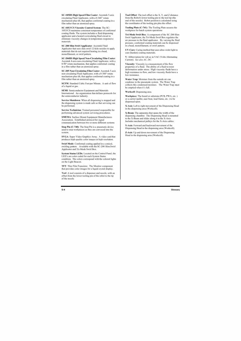
8/16/2019 Dispensig c 740 nordson
http://slidepdf.com/reader/full/dispensig-c-740-nordson 236/240
G-4 Glossary
SC-105HS High Speed Film Coater: Asymtek 5-axis
circulating Fluid Applicator, with a 0-360° rotate
mechanism plus tilt, that applies conformal coating in a
film rather than an atomized spray.
SC-10XVCS Viscosity Control System: The SC-
10XVCS maintains consistent temperature of conformal
coating fluids. The system includes a fluid dispensing
applicator and a heated recirculating fluid circuit to
eliminate viscosity changes in temperature-responsivematerials.
SC-200 Slim Swirl Applicator: Asymtek Fluid
Applicator that uses slim swirl 12-hole nozzles to apply
materials that do not required heating in a bead,
monofilament, or swirl pattern.
SC-204HS High Speed Non-Circulating Film Coater:
Asymtek 4-axis non-circulating Fluid Applicator, with a
0-90° rotate mechanism, that applies conformal coating
in a film rather than an atomized spray.
SC-205 Non-Circulating Film Coater: Asymtek 5-axis
non-circulating Fluid Applicator, with a 0-360° rotate
mechanism plus tilt, that applies conformal coating in afilm rather than an atomized spray.
SCFM: Standard Cubic Feet per Minute. A unit of flow
of a liquid or gas.
SEMI: Semiconductor Equipment and Materials
International. An organization that defines protocols for
the semiconductor industry.
Service Shutdown: When all dispensing is stopped and
the dispensing system is made safe so that servicing can
be performed.
Service Technician: Trained personnel responsible for
performing advanced system servicing procedures.
SMEMA: Surface Mount Equipment Manufacturers
Association. Established protocol for signal
communication between two or more different systems.
Stop Pin (C-740): The Stop Pin is a pneumatic device
used to stop workpieces as they are conveyed into the
system.
SVGA: Super Video Graphics Array. A video card that
produces high-quality color images at high resolution.
Swirl Mode: Conformal coating applied in a conical,
swirling pattern. Available with the SC-200 Slim Swirl
Applicator and Tri-Mode Swirl Box.
System Status LEDs: Located on the Control Panel, theLED’s are color coded for each System Status
condition. The colors correspond with the colored lights
on the Light Beacon.
TFT: Thin Film Transistor. The Monitor component
that provides color images for a liquid crystal display.
Tool: A tool consists of a dispenser and nozzle, with an
offset from the lower tooling pin of the robot to the tip
of the nozzle.
Tool Offset: The tool offset is the X, Y, and Z distance
from the Robot's lower tooling pin to the tool tip (the
end of the nozzle). Robot position is calculated using
the coordinates of the tooling pin plus the offset.
Tooling Plate (C-741): The Tooling Plate secures the
workpiece for batch system operations.
Tri-Mode Swirl Box: A component of the SC-200 Slim
Swirl Applicator, the Tri-Mode Swirl Box regulates theair pressure to the fluid applicator. By varying the fluid
pressure, conformal coating materials can be dispensed
in a bead, monofilament, or swirl pattern.
UV-Cure: Curing method that uses ultra-violet light to
cure (harden) coating materials.
V: Abbreviation for volt as in VAC (Volts Alternating
Current). See also AC, DC.
Viscosity: Viscosity is a measurement of the flow
properties of a fluid. The ability of a fluid to resist
deformation under stress. High viscosity fluids have a
high resistance to flow, and low viscosity fluids have a
low resistance.
Water Trap: Moisture from the outside air can
condense in the pneumatic system. The Water Trap
collects this condensed moisture. The Water Trap must
be emptied when it’s full.
Workcell: Dispensing area.
Workpiece: The board or substrate (PCB, PWA, etc. )
or a carrier (pallet, auer boat, lead frame, etc. ) to be
dispensed upon.
X-Axis: Left to right movement of the Dispensing Head
in the dispensing area (Workcell).
X-Beam: The apparatus that spans the width of the
dispensing chamber. The Dispensing Head is mountedto the X-Beam and slides along it in the X-Axis.
Includes mechanical pulleys for the X-Axis cables.
Y-Axis: Forward and backward movement of the
Dispensing Head in the dispensing area (Workcell).
Z-Axis: Up and down movement of the Dispensing
Head in the dispensing area (Workcell).
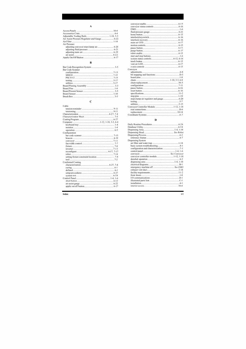
8/16/2019 Dispensig c 740 nordson
http://slidepdf.com/reader/full/dispensig-c-740-nordson 237/240
Index I-1
Index
A
Access Panels ............................................................... 10-4Accessories Crate............................................................ 4-4Adjustable Tooling Rails ....................................... 1-10, 3-3
Air Assist Pressure Regulator and Gauge ..................... 6-22Air Filter ....................................................................... 1-14Air Pressure
adjusting conveyor stop/clamp air............................ 6-20adjusting fluid pressure ............................................ 6-21
adjusting main air..................................................... 6-19air assist ................................................................... 6-22
Applic On/Off Button ................................................... 6-17
B
Bar Code Recognition System ........................................ 3-5Bar Code Scanner
configuration............................................................ 7-15
MS810 ..................................................................... 7-15
PSC5312 .................................................................. 7-15testing....................................................................... 5-17utilities ..................................................................... 5-17
Board Pinning Assembly ................................................ 3-3Board Pins ...................................................................... 1-8Board Present Sensor ...................................................... 3-5Board Sensor................................................................. 1-10
Brush Box ....................................................................... 3-5
C
Cable
tension reminder ...................................................... 9-11tensioning................................................................. 9-11
Characterization.....................................................6-27, 7-4Characterization Sheet .................................................... 7-5
Coating Program ........................................................... 6-27Computer ...............................................1-12, 1-18, 3-3, 6-4
keyboard tray ............................................................. 1-4monitor....................................................................... 1-4
operation .................................................................... 6-5Configuration
bar code scanner....................................................... 7-15 beacon...................................................................... 4-19conveyor .................................................................. 7-11fan width control ........................................................ 7-7
fixture......................................................................... 7-8inverter..................................................................... 7-13reconfigure...................................................... 4-17, 7-17robot......................................................................... 7-14
setting fixture constraint location ............................... 7-8tool ............................................................................. 7-2Conformal Coating
characterization.................................................6-27, 7-4
curing ......................................................................... 6-1defined ....................................................................... 6-1setup procedures ...................................................... 6-27system test................................................................ 6-28
Control Panel........................................................... 1-4, 1-6abort button .............................................................. 6-13air assist gauge ......................................................... 6-22applic on/off button.................................................. 6-17
conveyor enable........................................................6-15conveyor status controls ...........................................6-16
EMO...........................................................................1-6fluid pressure gauge..................................................6-21home button..............................................................6-15interlock keyswitch...................................................6-16
interlock recovery.....................................................6-16main air LED............................................................6-17motion controls.........................................................6-15
pause button..............................................................6-13 purge button..............................................................6-17robot enable..............................................................6-15
start and stop buttons..................................................1-6system status controls......................................6-12, 6-16teach button ..............................................................6-15vent air LED.............................................................6-17
z-axis controls ..........................................................6-15Conveyor
adjustments.................................................................6-8 bit mapping and functions .........................................D-3 board pins ...................................................................1-8
chain .......................................................... 1-10, 3-3, 6-8chain replacement.....................................................10-5configuration ............................................................7-11
pause button..............................................................6-16
reset button...............................................................6-16specifications............................................................11-2stop pins ...................................................................1-10
stop/clamp air regulator and gauge...........................6-20testing .........................................................................5-7utilities......................................................................5-15
Conveyor Controller Module ...............................1-12, 1-18rear connections.........................................................D-6replacement ............................................................10-14
Coordinate Systems.........................................................6-7
D
Daily Routine Procedures..............................................6-26Database Utility.............................................................6-34Dispensing Area.....................................................1-4, 1-10
Dispensing Head .................................................. See Robot Dispensing Process..........................................................6-2
reference frames .........................................................6-7
Dispensing Systemair filter and water trap .............................................1-14
basic system troubleshooting......................................8-1configuration and characterization .............................7-1
control panel ........................................................1-4, 1-6conveyor.................................................... See Conveyor conveyor controller module.............................1-12, 1-18detailed operation .......................................................6-2
dispensing area ..................................................1-4, 1-10electrical diagrams..................................................... B-1emergency machine off ....................................See EMO exhaust vent duct......................................................1-14
facility requirements.................................................11-2front doors ..................................................................1-8I/O communications ..................................................D-1illustrated parts lists................................................... C-1
installation..................................................................4-1interior access...........................................................10-4
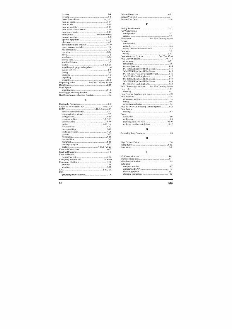
8/16/2019 Dispensig c 740 nordson
http://slidepdf.com/reader/full/dispensig-c-740-nordson 238/240
I-2 Index
levelers....................................................................... 1-4
leveling ...................................................................... 4-5lower front cabinet ............................................1-4, 1-12main air gauge.......................................................... 1-14
main air inlet ............................................................ 1-14main air regulator ..................................................... 1-14main power circuit breaker ...................................... 1-18main power inlet ...................................................... 1-18
maintenance ..........................................See Maintenance
manuals supplied........................................................ 1-2optional equipment.............................................. 1-3, 3-5
placement................................................................... 4-3
power buttons and switches ..................................... 6-10 power manager module............................................ 1-18rear connections ........................................................ D-8rear view .................................................................. 1-14
safety.......................................................................... 2-1shutdown.................................................................. 6-24solvent cups ............................................................... 1-8standard features ........................................................ 1-3
startup ............................................................... 5-1, 6-23stop/clamp air gauge and regulator .......................... 1-16system features........................................................... 1-4
testing......................................................................... 5-5
uncrating .................................................................... 4-2unpacking................................................................... 4-4
warranty ................................................................... 10-2Dispensing Valve........................ See Fluid Delivery System Door Sensors................................................................. 2-15Drive System
specifications ........................................................... 11-2Dual Toggle Mounting Bracket ...................................... 3-6Dual-Simultaneous Mounting Bracket............................ 3-6
E
Earthquake Precautions................................................... 2-6Easy Coat for Windows XP ................................. See ECXP ECXP.....................................................1-12, 3-3, 6-4, 6-27
bar code scanner utilities.......................................... 5-17characterization wizard .............................................. 7-7configuration............................................................ 4-15conveyor utilities............................................... 5-7, 5-15
database utility ......................................................... 6-34exiting ............................................................... 4-18, 5-4flow meter test ......................................................... 5-17inverter utilities ........................................................ 5-15
loading a program .................................................... 6-29 pendant..................................................................... 5-13reconfigure............................................................... 4-16robot utilities.............................................................. 5-6rotate tool ................................................................. 5-13
running a program.................................................... 6-31starting .....................................................4-16, 5-4, 6-23
Electrical Connections .................................................. 4-12Electrical Diagrams ........................................................B-1Electrical Power
lock out/tag out ........................................................ 2-12
Emergency Machine Off........................................See EMO Emergency Shutdown ................................................... 2-10
recovery ................................................................... 2-11situations.................................................................. 2-11
EMO ...................................................................... 1-6, 2-10ESD
grounding strap connector.......................................... 1-6
Exhaust Connection ......................................................4-12
Exhaust Vent Duct ..........................................................3-4Exhaust Vent Duct ........................................................1-14
F
Facility Requirements ...................................................11-2Fan Width Control
configuration ..............................................................7-7setup ...........................................................................7-7
Film Coater .................................See Fluid Delivery System Fixture
configuration ..............................................................7-8
defined........................................................................6-6setting fixture constraint location ...............................7-8
Flow Meter ......................................................................3-8testing.......................................................................5-17
Flow Monitoring System.............................See Flow Meter Fluid Delivery System.................................. 1-3, 1-10, 3-14
air pressure ...............................................................6-21installation..................................................................4-6
micro-adjustment......................................................3-14SC-104HS High Speed Film Coater.........................3-15SC-105HS High Speed Film Coater.........................3-15
SC-10XVCS Viscosity Control System ...................3-16SC-200 Slim Swirl Applicator..................................3-17SC-204HS High Speed Film Coater.........................3-19SC-205HS High Speed Film Coater.........................3-19SC-300 Swirl Coat Applicator..................................3-20
Fluid Dispensing Applicator .......See Fluid Delivery System Fluid Filter.....................................................................1-14
cleaning ......................................................................9-7
Fluid Pressure Regulator and Gauge.............................6-21Fluid Reservoir..............................................................1-14
air pressure switch....................................................1-16
filling..........................................................................9-4switching mechanism ...............................................1-14
Fluid SC-10XVCS Viscosity Control System...............3-16Fluid System
flushing.......................................................................9-5Fuses
description................................................................2-19replaceable................................................................10-8
replacing main line fuses ........................................10-10replacing panel mounted fuses ...............................10-12
G
Grounding Strap Connector.............................................1-6
H
High Pressure Fluids .......................................................2-4Home Button.................................................................6-15Hour Meter ......................................................................3-8
I
I/O Communications ...................................................... D-1Illustrated Parts Lists......................................................C-1
Inline Inverter Module ....................................................3-9Installation
computer monitor .......................................................4-7configuring ECXP ....................................................4-15
dispensing system.......................................................4-1electrical connections ...............................................4-12
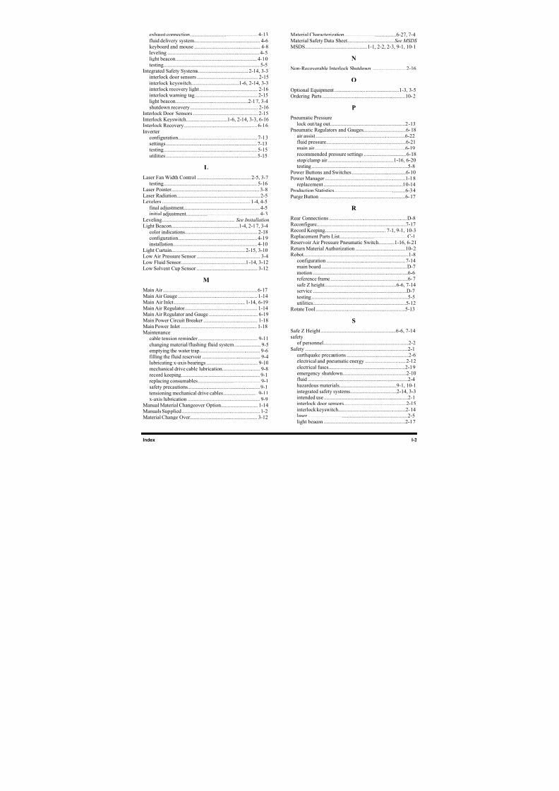
8/16/2019 Dispensig c 740 nordson
http://slidepdf.com/reader/full/dispensig-c-740-nordson 239/240
Index I-3
exhaust connection................................................... 4-13
fluid delivery system.................................................. 4-6keyboard and mouse .................................................. 4-8leveling ...................................................................... 4-5
light beacon.............................................................. 4-10testing......................................................................... 5-5
Integrated Safety Systems...................................... 2-14, 3-3interlock door sensors .............................................. 2-15
interlock keyswitch....................................1-6, 2-14, 3-3
interlock recovery light ............................................ 2-16interlock warning tag ............................................... 2-15light beacon.......................................................2-17, 3-4
shutdown recovery ................................................... 2-16Interlock Door Sensors ................................................. 2-15Interlock Keyswitch...............................1-6, 2-14, 3-3, 6-16Interlock Recovery........................................................ 6-16
Inverterconfiguration............................................................ 7-13settings ..................................................................... 7-13testing....................................................................... 5-15
utilities ..................................................................... 5-15
L
Laser Fan Width Control .........................................2-5, 3-7testing....................................................................... 5-16
Laser Pointer................................................................... 3-8Laser Radiation............................................................... 2-5Levelers ................................................................... 1-4, 4-5
final adjustment.......................................................... 4-5initial adjustment........................................................ 4-3
Leveling.......................................................See Installation Light Beacon...................................................1-4, 2-17, 3-4
color indications....................................................... 2-18configuration............................................................ 4-19installation................................................................ 4-10
Light Curtain........................................................ 2-15, 3-10Low Air Pressure Sensor ................................................ 3-4Low Fluid Sensor.................................................1-14, 3-12
Low Solvent Cup Sensor .............................................. 3-12
M
Main Air ....................................................................... 6-17Main Air Gauge ............................................................ 1-14
Main Air Inlet ...................................................... 1-14, 6-19Main Air Regulator....................................................... 1-14Main Air Regulator and Gauge ..................................... 6-19
Main Power Circuit Breaker ......................................... 1-18Main Power Inlet .......................................................... 1-18Maintenance
cable tension reminder ............................................. 9-11
changing material/flushing fluid system.................... 9-5emptying the water trap.............................................. 9-6
filling the fluid reservoir ............................................ 9-4lubricating x-axis bearings ....................................... 9-10
mechanical drive cable lubrication............................. 9-8record keeping............................................................ 9-1replacing consumables ............................................... 9-1safety precautions....................................................... 9-1
tensioning mechanical drive cables.......................... 9-11x-axis lubrication ....................................................... 9-9
Manual Material Changeover Option............................ 1-14Manuals Supplied ........................................................... 1-2Material Change Over................................................... 3-12
Material Characterization .......................................6-27, 7-4Material Safety Data Sheet...................................See MSDS MSDS...............................................1-1, 2-2, 2-3, 9-1, 10-1
N
Non-Recoverable Interlock Shutdown ..........................2-16
O
Optional Equipment .................................................1-3, 3-5Ordering Parts ...............................................................10-2
P
Pneumatic Pressure
lock out/tag out.........................................................2-13Pneumatic Regulators and Gauges................................6-18
air assist ....................................................................6-22fluid pressure............................................................6-21
main air.....................................................................6-19recommended pressure settings ................................6-18stop/clamp air..................................................1-16, 6-20testing .........................................................................5-8
Power Buttons and Switches .........................................6-10
Power Manager .............................................................1-18replacement ............................................................10-14
Production Statistics......................................................6-34
Purge Button .................................................................6-17
R
Rear Connections ...........................................................D-8
Reconfigure...................................................................7-17Record Keeping.............................................. 7-1, 9-1, 10-3Replacement Parts List...................................................C-1Reservoir Air Pressure Pneumatic Switch............1-16, 6-21
Return Material Authorization ......................................10-2Robot...............................................................................1-8
configuration ............................................................7-14
main board.................................................................D-7motion ........................................................................6-6reference frame...........................................................6-7safe Z height......................................................6-6, 7-14service .......................................................................D-7
testing .........................................................................5-5utilities......................................................................5-12
Rotate Tool ....................................................................5-13
S
Safe Z Height .........................................................6-6, 7-14safety
of personnel................................................................2-2
Safety ..............................................................................2-1
earthquake precautions ...............................................2-6electrical and pneumatic energy ...............................2-12
electrical fuses..........................................................2-19emergency shutdown................................................2-10fluid ............................................................................2-4
hazardous materials...........................................9-1, 10-1integrated safety systems...................................2-14, 3-3intended use ................................................................2-1interlock door sensors...............................................2-15
interlock keyswitch...................................................2-14laser ............................................................................2-5light beacon ..............................................................2-17
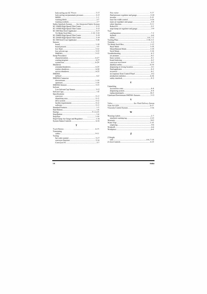
8/16/2019 Dispensig c 740 nordson
http://slidepdf.com/reader/full/dispensig-c-740-nordson 240/240
lock out/tag out AC Power....................................... 2-12
lock out/tag out pneumatic pressure......................... 2-13MSDS ........................................................................ 1-1warning labels ............................................................ 2-7
warning symbols ........................................................ 2-7Safety Interlock System.........See Integrated Safety Systems SC-104HS High Speed Film Coater ............................. 3-15SC-105HS High Speed Film Coater ............................. 3-15
SC-200 Slim Swirl Applicator ...................................... 3-17
Tri-Mode Swirl Box........................................1-12, 3-18SC-204HS High Speed Film Coater ............................. 3-19SC-205HS High Speed Film Coater ............................. 3-19
SC-300 Swirl Coat Applicator ...................................... 3-20Sensors
b d 1 10
flow meter ................................................................5-17
fluid pressure regulator and gauge............................5-10inverter .....................................................................5-15laser fan width control..............................................5-16
main air regulator and gauge ......................................5-8robot function...........................................................5-11Robot I/O....................................................................5-5stop/clamp air regulator and gauge.............................5-9
Tool
configuration ..............................................................7-2defined........................................................................6-6offset....................................................................6-6, 7-2
Tooling Plate ..........................................................1-10, 3-3Training...........................................................................1-2T i M d S i l B 1 12