Embed Size (px)
Citation preview
8/4/2019 Dislocations Paper
http://slidepdf.com/reader/full/dislocations-paper 1/6
Journal of Materials Education Vol. 25 (4-6): 113 - 118 (2003)
MODELS OF DISLOCATIONS FOR CLASSROOM ***
R. Prasad
Department of Applied Mechanics, Indian Institute of Technology, Hauz Khas, New Delhi 110 016,
India; [email protected]
ABSTRACT
Three-dimensional models for dislocation studies in crystal structures are suggested, which can be
made by students to improve understanding of the concepts.
Keywords: dislocation models; teaching strategies
INTRODUCTION ∗∗∗
Crystal structures and associated defects are
important concepts taught in introductorycourses in materials science to engineering
undergraduates1. Presentations of these
concepts require three-dimensional
visualization. Thus two-dimensional figures
used in textbooks or drawn on blackboards are
often inadequate in imparting a clear view of
crystals or defects. To overcome this problem
most teaching laboratories in material science
present students with three-dimensional models.
These models are often successful in showing
concepts related to periodicity, coordination
number, close packing etc. However, in the
∗∗∗ NOTE: This manuscript replaces the
preliminary version that was published in error
by JME in Volume 24 (4-6): 255-258 (2002). The
Journal regrets this mistake, and urges readers to
discard the previous version.
view of this author, in most cases, the models
for dislocations in crystal, are not adequate. In
the present work a simple method for making
attractive models for dislocations in crystalstructure is suggested.
MODEL MAKING
The models are built by using 'atoms' and
'bonds' supplied by Cochranes of Oxford 2.
Atoms are just little plastic spheres from which
emerge six arms (along the six nearest
neighbours in a simple cubic lattice). Bonds are
plastic tubes, which are used to join atoms. By
joining sufficient number of atoms with help of bonds a three-dimensional simple cubic lattice
can be easily constructed. By suitable alteration
in the joining scheme different kinds of
dislocations can be introduced in the structure.
At present we have made following models
with different dislocation configurations.
8/4/2019 Dislocations Paper
http://slidepdf.com/reader/full/dislocations-paper 2/6
Prasad
Journal of Materials Education Vol. 25 (4-6)
114
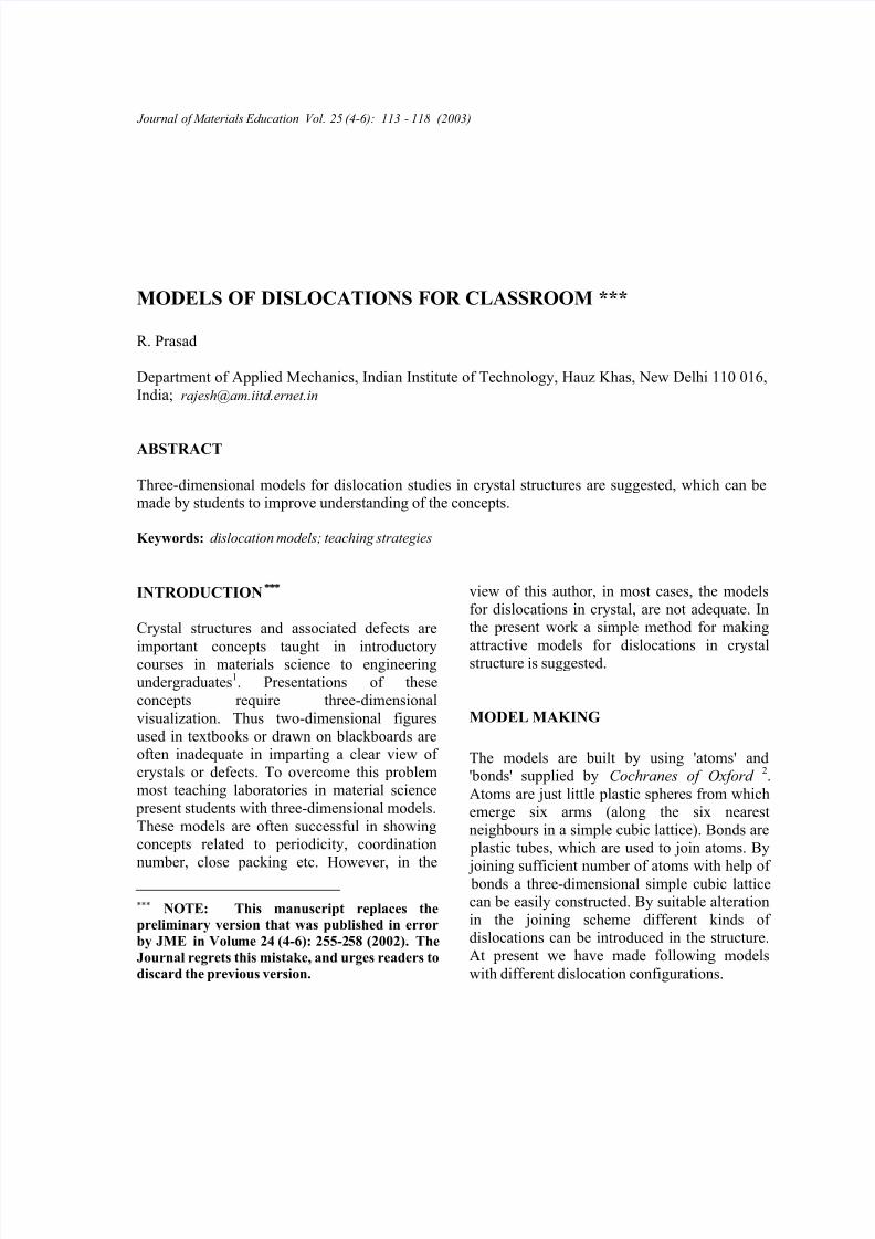
EDGE DISLOCATION
If one half of one of the planes from the lattice
is removed one gets a model for an edge
dislocation, Fig. 1. Students can easily follow a
Burgers circuit around the dislocation todetermine that Burgers vector is perpendicular
to the dislocation line. Such a circuit can be
shown by using atoms of different colour toidentify the circuit.
Fig. 1. A model of an edge dislocation. The
dislocation symbol ⊥ identifies its approximatelocation. (432 atoms, 55cm % 38cm % 15 cm)
SCREW DISLOCATION
Screw dislocation presents greater difficulty invisualization than edge dislocation. The model
shown in Fig. 2 is thus very useful in showing
the spiral ramp configuration of atomic planes
around a screw dislocation. Burgers circuit can
also be easily constructed to demonstrate that
the Burgers vector is parallel to the dislocation
line.
Fig. 2(a)
Fig. 2(b)
Fig. 2 (a) and (b). Two views of a model of a right-handed screw dislocation. The dashed lines indicates
the approximate location of the dislocation line (525
atoms, 45cm % 20cm % 15cm)
MIXED DISLOCATION
The concept of mixed dislocation often causes
greater difficulty for students. The model
shown in Fig. 3 has been constructed in a way
that the mixed dislocation line consists of two
pure segments meeting at 90° inside the crystal.
One of the segments is edge and the other is
screw. In Fig. 3 the dislocation enters the front
face ABCD at L as an edge dislocation, takes a
90° turn inside the crystal and comes out of theleft face as a screw dislocation. To bring this
out clearly a schematic of the model is shown in
Fig. 4. Same letters in Figs. 3 and 4 represent
identical locations in the model and the
schematic. Thus Fig. 3 is the front view of the
schematic model shown in Fig. 4. PQRS is the
slip plane on which lies the dislocation line
⊥

8/4/2019 Dislocations Paper
http://slidepdf.com/reader/full/dislocations-paper 3/6
Models of Dislocations for Classroom
Journal of Materials Education Vol. 25 (4-6)
115
Fig. 3. A model of a mixed dislocation. (720
atoms, 45cm % 39 cm % 30 cm)
Fig. 4. A schematic of the model shown in Fig. 3.
LMN . The orientation of the Burgers vector b is
also shown. The segment LM is an edge and
the segment MN is a screw dislocation.
This model can be used to illustrate the
principle that a dislocation line cannot end
abruptly inside a crystal. When a student looks
at face ABCD of the model (Figs. 3 and 4) he
sees that an edge dislocation enters the crystal
at L. When he turns the model over to look at
the opposite face EFGH , where he expects the
dislocation to come out, he finds none, Fig. 5.This may give him a feeling that the dislocation
entering the face ABCD has abruptly ended
within the crystal. A further examination of the
model then reveals that a screw dislocation also
enters into the crystal at N on face ADEF .
Again this dislocation does not come out of the
opposite face BCHG. One then finds that the
Fig. 5. The same model as in Figs. 3 and 4, butviewed from behind. The same letter corresponds to
identical locations in the three figures.
two segments LM and MN actually meet at M .
Thus LMN should be considered as a singlemixed dislocation entering the crystal at L,
abruptly changing its direction and character at
M and finally coming out at N . So there is no
abrupt end of the dislocation line inside the
crystal, only an abrupt change in its direction
and character.
The model can also be used to illustrate another
principle of dislocation theory. The Burgers
vector of the dislocation does not change even
when a dislocation changes its direction3.
Students can make Burgers circuit around the
dislocation on both the front ABCD and the left
ADEF faces and find that it is the same.
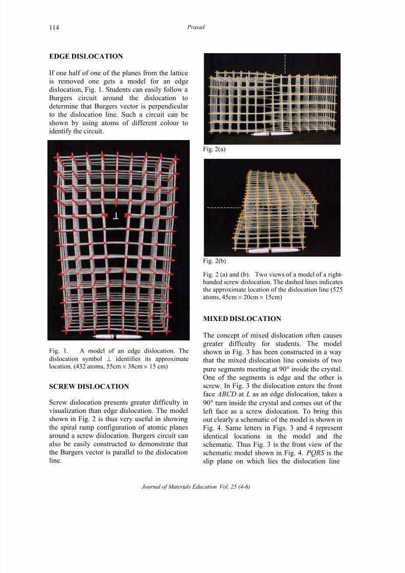
PRISMATIC DISLOCATION LOOP
This configuration is obtained by inserting an
extra layer of 9 atoms (3%3) in the middle of the
model, Fig. 6. The square boundary of this layer
is an edge dislocation with Burgers vector
perpendicular to the layer surface. This model
shows that dislocation lines may form a loop
inside a crystal. This model shows a prismaticdislocation loop due to a layer of interstitials. A
similar model showing a prismatic dislocation
loop due to a layer of vacancies has also been
constructed.
The viewing direction of Fig. 6 lies in the plane
of the loop. It thus shows the loop in edge-on
GF
A B
R S
M N
D
H E
C
P Q
L
GF
A B
R S
M N
D
H E
D
H E
C
P Q
L
E
FG
H
R S
E
FG
H
R S
A B
CD
P QL
A B
CD
P QL
8/4/2019 Dislocations Paper
http://slidepdf.com/reader/full/dislocations-paper 4/6
Prasad
Journal of Materials Education Vol. 25 (4-6)
116
Fig. 6. A model of a prismatic dislocation loop.
The viewing direction lies in the plane of the loop.
The visible segment is one side of the square loop
between the two dislocation symbols. (685 atoms,38 cm % 38 cm % 12 cm)
Fig. 7. Same model as in Fig. 6 but viewed in adirection normal to the loop. The loop is not
revealed in this orientation. It lies directly below the
square of nine atoms (whose corners are identifiedas a, b, c and d) in the centre of the figure.
position with only one side of the square visible
between the dislocation symbols marked on the
figure. This is deliberate, as a view along
normal to the plane of the loop, Fig. 7, does not
show the loop due to perfect alignment of
atoms within the loop and outside it in this
direction. The loop lies directly below the
square marked abcd . Thus although it is
common to show a loop in schematic diagrams
in this orientation, a three-dimensional model
like this one will not reveal the presence of the
loop. This fact emphasizes the need for working
with three-dimensional models to get a good
feel of the dislocation geometry.
LOW ANGLE SYMMETRIC TILT
BOUNDARY
This model, Fig. 8, clearly shows a low angle
symmetric tilt boundary as a series of parallel
edge dislocations. Students can measure thedistance d between the successive dislocations,
Burgers vector b and the tilt angle θ of the
model and thus verify the formula3
b
d 2 2= sin
θ.
Fig. 8. A model of a symmetric tilt boundary. The
dislocations are approximately located at the
symbols ⊥. The symmetric tilt boundary is the
vertical plane passing through these locations. (477
atoms, 55 cm % 30 cm % 8 cm)
CONCLUSIONS
It is expected that these models will help
students understand difficult concepts related to
dislocations. Nowadays there are several
teaching aids based on interactive computer
graphics available on CD-ROMs and the Web4.
⊥ ⊥⊥
a b
cd
a b
cd
⊥
⊥
⊥
⊥
⊥
⊥
⊥
⊥
8/4/2019 Dislocations Paper
http://slidepdf.com/reader/full/dislocations-paper 5/6
Models of Dislocations for Classroom
Journal of Materials Education Vol. 25 (4-6)
117
In our opinion, solid three-dimensional models
often offer better visualization than computer
graphics. The models presented here have been
tested in an introductory course on materials
science for undergraduate engineering students.
The response of the students have beenfavourable and enthusiastic.
Another teaching idea can be to give students
atoms and bonds and let them construct the
models for themselves. This will probably lead
to better understanding than simply observing
the models constructed by someone else. In
fact, all the models presented here has been
constructed by the students, although not in
classroom but outside it.
Only five models are discussed here. Other
models can also be made. For example, like the
symmetric tilt boundary consisting of parallel
edge dislocations shown here, model for a twist
boundary comprising of parallel screw
dislocations can also be made. Similarly, a
dislocation loop which is not prismatic and
hence changes its character along the loop can
also be constructed.
REFERENCES
1. W.D. Callister, Materials Science and
Engineering: An Introduction, 5th. Edition.,
Wiley, New York, 2001
2. http://www.cochranes.co.uk
3. D. Hull and D.J. Bacon, Introduction to Dislocations, 4th. Edition., Butterworth-
Heinemann, 2001.
4. Materials Science on CD-ROM: An Interactive Tool for Students, Version 2.1,
(www.liv.ac.uk/~matter)
ACKNOWLEDGEMENTS
I am grateful to several of my students who
voluntarily spent several painstaking hours to
build the models. Prominent among these are
M.V. Sandeep, Anand Ahlawat and R.
Krishnakishore and Sugandh Malhotra. Another
student, S. Giribaskar, helped in preparation of
the manuscript. I would like to thank Prof. R.K.
Pandey, Head of the Department of Applied
Mechanics for his enthusiastic encouragement
for the construction of the models. Finally, I
would like to thank the referee whose careful
comments helped a lot in improving the
presentation.
8/4/2019 Dislocations Paper
http://slidepdf.com/reader/full/dislocations-paper 6/6
Prasad
Journal of Materials Education Vol. 25 (4-6)
118
This page intentionally left blank


![CONFINEMENT OF DISLOCATIONS INSIDE A CRYSTAL WITH Acvgmt.sns.it/media/doc/paper/3209/LMSZ-dislocations.pdf · and [6] for edge dislocations), the theory of Ginzburg-Landau vortices](https://img.pdfslide.us/doc/110x75/5f043ead7e708231d40d0624/confinement-of-dislocations-inside-a-crystal-with-and-6-for-edge-dislocations.jpg)