Embed Size (px)
Citation preview

ct
cotlTwou
Disk-type multiplex holography
Yih-Shyang Cheng, Wei-Hong Su, and Ray-Cheng Chang
A theory for making a disk-type multiplex hologram is derived. This theory relates the final image point,as seen by the observer, to a point on the original three-dimensional object through a set of equations.From these equations the distortion of the image and the wavelength as seen by each individual eye canbe evaluated. Computer simulation shows the characteristics of this hologram. Some experimentalresults also confirm these characteristics. By reversing the process and specifying a desired image, wegenerated a set of distorted two-dimensional originals. The hologram fabricated with these distortedimages can generate nearly distortion-free images. © 1999 Optical Society of America
OCIS codes: 090.0090, 090.4220, 090.5640.
1. Introduction
Multiplex holography is a combination of photogra-phy and rainbow holography.1 The photographicprocess provides the simple means to access differentviews of the object, whereas the rainbow holographicprocess facilitates the viewing of a three-dimensional~3D! image with an ordinary lightbulb. The mostommercially successful cylindrical stereogram washat developed by L. Cross.2 To produce the stereo-
gram, pictures of the object are taken with a camerafrom different directions by successive rotation of theobject between successive exposures. The resultantphotograph is then converted into a long thin holo-gram by an anamorphic optical system3,4 that imagesthe vertical image onto the hologram plane while thehorizontal one is projected onto ~or near! the finalylindrical lens, which then compresses the wholebject into a vertical line. Successive frames of pho-ographs are converted into successive long thin ho-ograms, thus resulting in a composite hologram.his hologram, when bent into a cylinder and viewedith a white-light source, exhibits the characteristicsf a rainbow hologram. This type of hologram wassed to reconstruct 3D image from tomographic data5
and to the field of computer aided design.6 Morerecently, a hologram called a conical holographic ste-reogram7,8 was introduced that is capable of project-
The authors are with the Institute of Optical Sciences, NationalCentral University, Chungli, Taiwan 32054, China. Y.-S. Cheng’se-mail address is [email protected].
Received 12 June 1998; revised manuscript received 5 February1999.
0003-6935y99y143093-08$15.00y0© 1999 Optical Society of America
ing a 3D image above the open end of the hologramcone. Since the technology for compact disks ishighly developed at present, one might consider thepossibility of fabricating a multiplex hologram on adisk that is suitable for mass production. With thisin mind we show that it is indeed possible to achievethis task. By using coordinate transformation andgeometrical consideration, we obtain the relationshipbetween the original two-dimensional ~2D! photo-graphs and the 3D object. From the geometrical re-lationship with respect to the hologram, the incidentobject ray direction and the diffracted ray directionare determined. The reconstructed image ray canbe seen by one eye of the observer when that partic-ular hologram strip is rotated to some suitable angle.Two line equations for both eyes of the observer de-fine the 3D position of the reconstructed image.From the developed mathematical relations, if wereverse the process, a disk-type multiplex hologram,which is capable of generating a nearly distortion-free image, is proposed. The effects of various pa-rameters, which affect the image quality, wereconsidered by use of both numerical analysis andexperimental demonstration.
2. Theory
As seen in Fig. 1 an object is situated in the x–y–zcoordinate system, where the z axis is the axis ofrotation for the object. A camera ~in our case, a CCDcamera! with its optical axis on the x9 axis is aimed atthe origin of the coordinate system. The x9–y–z9 co-ordinate system is a rotated version of the x–y–z co-ordinate system with respect to the y axis by an angle2py2 1 a0. Hence the angle between the x9 axis andthe z axis is a0. Consider a generalized object pointA0 that is at ~l sin au cos af, l sin au sin af, l cos au!
10 May 1999 y Vol. 38, No. 14 y APPLIED OPTICS 3093

ih
@
Ad
efi
3
in the ~x, y, z! coordinates. Since the object is on arotational stage, the coordinates of this object pointare changed to @l sin au cos~af 1 Daf!, l sin au sin~af
1 Daf!, l cos au# when the object is rotated by an angleDaf about the z axis. To find the position of themage of this point object on the detector plane, weave to use the rotated coordinate system ~x9, y, z9!,
since the detector plane is parallel to the y–z9 plane.In the new coordinate system the coordinates of theobject point A0 become
l~cos a0 cos af 1 sin a0 sin au cos af!,
l sin au sin af, l~sin a0 cos au 2 cos a0 sin au cos af!#.
With the knowledge that the distance between thelens of the CCD camera and the origin of the coordi-nate system ~the detector plane! is z0~zi!, the imageposition on the detector is found to be at
~x, y! 5 F zil sin au sin af
z0 2 l~cos a0 cos au 1 sin a0 sin au cos af!,
3zil~sin a0 cos au 2 cos a0 sin au cos af!
z0 2 l~cos a0 cos au 1 sin a0 sin au cos af!G . (1)
This image is transmitted to the real-time displaydevice, which in our case is a liquid-crystal television~LCTV!, in the anamorphic optical system ~Fig. 2!.
ssuming that the magnification ratio from the CCDetector to the LCTV is k1, the horizontal magnifica-
tion ratio from LCTV to the horizontal image plane isku and the vertical magnification ratio from LCTV tothe plane of the slit ~the recording holographic film! iskvRy~R 1 h!. The image point D for the point objectA0, at the horizontal image plane, is at
~u, v! 5 F zik1 ku l sin au sin af
z0 2 l~cos a0 cos au 1 sin a0 sin au cos af!,
3zik1 kv l~sin a0 cos au 2 cos a0 sin au cos af!
z0 2 l~cos a0 cos au 1 sin a0 sin au cos af! G . (2)
Referring to Fig. 3, which is the enlargement of theright-hand part of the anamorphic optical system inFig. 2, the recording holographic film is placed at aplane parallel to the u–v plane and intersects the
Fig. 1. Object point A0 rotates about the z axis. The CCD cam-ra takes the image for every unit rotation of the object.
094 APPLIED OPTICS y Vol. 38, No. 14 y 10 May 1999
optical axis at the position O. A slit ~fan shaped!directly in front of the recording film limits the expo-sure area of the reference wave. Hence the recordedindividual hologram is a fan-shaped long thin strip.The horizontal image plane is a distance h in front ofthe film plane, whereas the image ~a horizontal line!plane of the illuminating source is at a distance Rbehind the slit plane. The light ray that originatesfrom the cylindrical lens and that goes through thehorizontal image point D would hit the vertical imagepoint A at the slit that is a distance b from the opticalaxis. This light ray would then reach the horizontalline at a distance R behind the slit ~or film! plane.Two angles u and fa are essential for defining the raydirection with respect to the film plane. As seenfrom the figure, u is the angle between AC and ADthat defines the horizontal azimuthal angle of thelight ray. Similarly, fa is that between AE and theoptical axis of the optical system that defines thevertical azimuthal angle of the light ray. With a
Fig. 2. Anamorphic optical system for multiplex hologram record-ing. The image magnification from the CCD detector to the LCTVis kl. From the LCTV to the horizontal image plane the magni-
cation ratio is ku. From the LCTV to the plane of the slit, themagnification ratio is kv@Ry~R 1 h!#. D is the horizontal image ofthe object point on the LCTV. The fan-shaped slit is utilized tolimit the recording area of the individual hologram.
Fig. 3. Geometry showing the orientation of the object ray DAEwith respect to the recording film at the slit plane. D is thehorizontal image, and A is the vertical image of the object point.The object ray is characterized by the three parameters b, u, andfa.

Its
w
w
w
U
o
Net
islcclwasoaset
simple geometrical relationship, the length OA is re-lated to the previous parameters by the equation
b 5 GCRy~R 1 h!, (3a)
where
GC 5zik1 kv l~sin a0 cos au 2 cos a0 sin au cos af!
z0 2 l~cos a0 cos au 1 sin a0 sin au cos af!.
(3b)
The angle fa is related to b by the equation
fa 5 tan21~byR!, (4)
whereas the angle u is equal to
u 5 tan21~CDyAC!, (5a)
where
CD 5zik1 ku l sin au sin af
z0 2 l~cos a0 cos au 1 sin a0 sin au cos af!,
(5b)
AC 5h
cos fa. (5c)
The above three variables u, fa, and b specify theincident direction of the object ray and the position onthe holographic film where the interference fringeswill be formed.
Now we are ready to find the spatial frequency ofthe interference fringes at point A on the film. Theobject ray ~wave! a can be expressed as ~Fig. 4!
a 5 a exp~2iku1 sin u0 1 ikw cos u0!, (6a)
where k is the wave number of the light and
u1 5 u cos fc 1 v sin fc. (6b)
This object ray is recorded on the holographic film~w 5 0! by interference with a reference wave ~ray! r,which can be written as
r 5 r exp~ikv sin h 1 ikw cos h!. (6c)
Fig. 4. Geometric relationship among object ray a, reference rayr, reconstruction reference ray r9, and reconstruction object ray a9.
n the horizontal direction the spatial frequency ofhe interference fringes, which is useful for recon-truction, is
fu 5sin u0
lcos fc, (7a)
hereas that in the vertical direction is
fv 5sin u0
lsin fc 1
sin h
l, (7b)
here l is the wavelength of the light.A reference wave denoted by r9 with wavelength l9
is used to reconstruct the image ray a9. These twowaves may be written as
r9 5 r exp~ik9v9 sin h9 1 ik9w cos h9!, (8a)
a9 5 a exp~2ik9u2 sin u9 1 ik9w cos u9!, (8b)
here
v9 5 v cos f 2 u sin f, (8c)
u2 5 u cos c 1 v sin c. (8d)
tilizing the following two identities,
sin u0 cos fc 5 sin u, (9a)
sin u0 sin fc 5 cos u sin fa, (9b)
we obtain two equations that relate the direction ofthe reconstructed object ray u9 and c to the originalbject ray direction u and fc:
sin u 5l
l9~sin u9 cos c
2 sin h9 sin f9!, (10a)
cos u sin fa 1 sin h 5 ~lyl9!~sin u9 sin c
1 sin h9 cos f9!. (10b)
ote that the direction of the reconstruction refer-nce ray h9 and f9 also comes into play in determininghe direction of the reconstructed object wave.
Below we build the relationship between the orig-nal object point and the image point as viewed by aingle eye. The holograms are recorded in the fol-owing procedure. Each 2D image taken by the CCDamera is transmitted through the anamorphic opti-al system ~Fig. 2! and is fabricated as a fan-shapedong thin rainbow hologram that is limited by the slitidth. Between each exposure the original objectnd the recording holographic film are rotated by amall amount of angle that corresponds to the widthf the slit so that the individual long thin hologramsre nonoverlapping. The finished hologram disk ishown in Fig. 5. Light from the reconstruction ref-rence source S9 reads the information about the par-icular object point that we considered above. The
10 May 1999 y Vol. 38, No. 14 y APPLIED OPTICS 3095

ef
f
saa
3
reconstructed object ray in the direction u9 and cgenerally cannot reach one of the eyes of the observerunless that hologram is rotated about the center ofthe disk to a specific angle. Assume that the eyes ofthe observer are situated symmetrically with respectto the w axis at ~6a, 0, R!. As shown in Fig. 5, whenpoint A belonging to a strip hologram is rotated by anangle d to reach point B, the reconstructed object raya9 from point B can reach the left eye of the observer.Hence the object point A0 that we considered can beseen by the left eye. Similarly, when another holo-gram strip is rotated counterclockwise to a particularangle, the reconstructed object ray a9 would reach theright eye of the observer. A set of equations thatrelate all the parameters in Fig. 5 can be obtained foreach eye of the observer:
~m 2 b!sin d 5 @t 2 p 2 ~m 2 b!cos d#tan f9, (11a)
f 5 d 1 f9 5 d 1 tan21
3 F ~m 2 b!sin d
t 2 p 2 ~m 2 b!cos dG , (11b)
n sin f9 5 ~m 2 b!sin d, (11c)
n 5~m 2 b!sin d
sin f95
~m 2 b!sin d
sin~f 2 d!,
(11d)
h 5 tan21St 2 m 1 bg D , (11e)
h9 5 tan21S ng 2 qD
5 tan21F ~m 2 b!sin d
~g 2 q!sin~f 2 d!G , (11f)
c 5 tan21Fs m 2 ~m 2 b!cos d
2a 1 ~m 2 b!sin dG , (11g)
u9 5 tan21
3($@~m 2 b!cos d 2 m#2 1 @sa 2 ~m 2 b!sin d#2%1y2
R ) ,
(11h)
where s 5 11 for the left eye and s 5 21 for the rightye. Using Eqs. ~10a! and ~10b!, we then have theollowing ten equations for each eye of the observer:
sin uj 5 sl
l9j~sin u9j cos cj 2 sin h9j sin f9j!, (12a)
cos uj sin faj1 sin h j 5
l
l9j~sin u9j sin cj 1 sin h9j cos f9j!
(12b)
096 APPLIED OPTICS y Vol. 38, No. 14 y 10 May 1999
bj 5R
R 1 h
zik1kvl~sin a0 cos au 2 cos a0 sin au cos afj!
z0 2 l~cos a0 cos au 1 sin a0 sin au cos afj!
,
(12c)
aj 5 tan21~bjyR!, (12d)
uj 5 tan21F zik1kul sin au sin afj~1yh!
z0 2 l~cos a0 cos au 1 sin a0 sin au cos afj!G ,
(12e)
fj 5 2sdj 2 s tan21F ~m 2 bj!sin dj
t 2 p 2 ~m 2 bj!cos djG , (12f)
hj 5 tan21Ft 2 m 1 bj
g G , (12g)
h9j 5 tan21F 2s~m 2 bj!sin dj
~g 2 q!sin~fj 1 dj!G , (12h)
cj 5 tan21F m 2 ~m 2 bj!cos dj
2sa 1 ~m 2 bj!sin djG , (12i)
u9j 5 tan21
3 ($@~m 2 bj!cos dj 2 m#2 1 @sa 2 ~m 2 bj!sin dj#2%1y2
R ).
(12j)
The variables l, m, t, g, p, q, a, R, l, a0, au, h, zi, z0,k1, ku, and kv are known. Meanwhile, in the aboveten equations there are ten unknown variables thatcan always be solved. Once the coordinates of theobject are specified, the viewing direction for the im-age point is determined for both the left eye and theright eye.
On the basis of the relationship between the objectpoint and the image point as viewed by a single eye,one can then calculate the 3D image location asviewed by both eyes simultaneously. The imagepoint A90 seen by different eyes are generated by therecorded interference fringes that are produced bydifferent photographs. Hence the following identityshould be satisfied:
2dr 1 dl 5 afl2 afr
, (13)
where the subscripts r and l denote the right eye andthe left eye, respectively, and the rotation ~angular!peeds for both the object platform ~about the z axis!nd the hologram disk ~about the center of disk! aressumed to be the same. Once the value of afl
isspecified, the values for ul, u9l, dl, cl, fl, hl, h9l, bl, andll can be obtained. From the above equation, thevalues for ur, u9r, dr, cr, fr, hr, h9r, br, lr, and afr
canalso be found. Hence the trajectory of every lightray of the image in the space can be calculated. Theimage position and the wavelength as seen by the leftand the right eyes can also be calculated.
Since the two eyes are at El~al, 0, R! and Er~ar, 0, R!

r
o
dwrr
e
B
and the two points on the hologram where the imagepoint is seen by an individual eye are at
Al@~m 2 bl!sin dl, m 2 ~m 2 bl!cos dl, 0# and Ar@~m 2 br!
3 sin dr, m 2 ~m 2 br!cos dr, 0#,
espectively, the equation Ll~Lr! for the line joiningthe left ~right! eye and the corresponding image pointn hologram can be found as
Ll:u 2 al
al 2 ~m 2 bl!sin dl5
v2m 1 ~m 2 bl!cos dl
5w 2 R
R,
(14a)
Lr:u 2 ar
ar 2 ~m 2 br!sin dr5
v2m 1 ~m 2 br!cos dr
5w 2 R9
R.
(14b)
These two lines do not intersect exactly. However,there is a position with a shortest distance betweenthem. The location of the image point A90 ~Fig. 6! istaken as the average location of two points ~ul, vl, wl!and ~ur, vr, wr! on the lines with the shortest distancebetween them.
Up to now, by specifying the location of the objectpoint A0, we have obtained the 3D image location A90in space. Below we discuss the problem of imagedistortion ~Fig. 7!. For the left eye the image A90 isseen through the hologram IAf, which contains the
Fig. 5. Disk-type multiplex hologram is placed on the u–v planeith its center I at the top of the figure. The object ray a9 is
econstructed by the reference wave from s9 ~s9, reconstructioneference source; s, reference source!. In the recording of holo-
gram the object ray and the reference wave from s produce inter-ference pattern at position A. When the hologram is rotated by anangle d and when this interference pattern is moved to point B, thereconstructed object ray a9 is seen by the left eye ~El! of the ob-server.
information of the object when one of the front sidesof the object is A0B0. However, the image B91 is pro-
uced by the hologram IBf, which contains the infor-mation when one of the front sides of the object isA1B1. From the above discussion, given afB1l
~pointB1 seen by the CCD camera!, dB1l, dB1r, uB1l, uB1r, u9B1l,u9B1r, l9B1l, l9B1r, and afB1r
for the image point B91 can befound. If the relationship between the object pointB1 and the object point A0 is found, then, for theimage point A90, dA0l, dA0r, uA0l, uA0r, u9A0l, u9A0r, l9A0l, l9A0r,and afA0r
can be calculated. The relationship be-tween afA0l
and afB1lis
dB1 l 2 dA0 l 5 afA0 l2 afB1 l
1 ~py2!, (15)
where dB1l and afB1lare known and dA0l and afA0l
areunknown. By specifying the relative position be-tween A0 and B1, we can calculate the relative posi-tion between two image points A90 and B91. Hence thedegree of distortion for the image can be evaluated.
Fig. 6. Configuration showing the image point A90 seen by the leftye ~al, 0, R! and the right eye ~ar, 0, R! through different holo-
grams at Al and Ar. Both eyes are situated on the u–w plane.The hologram is placed on the u–v plane.
Fig. 7. ~a! The object taken by the CCD camera at two differentdirections. ~b! These two photographs are recorded as hologramIAf and IBf, which are seen by two eyes of the observer correspond-ingly. For the left eye of the observer, the image A90 is seenthrough hologram IAf and B91 is seen through hologram IBf. Thetwo image points A90 and B91 correspond to the object points A0 and
1. Hence a distorted image is seen by an individual eye of theobserver.
10 May 1999 y Vol. 38, No. 14 y APPLIED OPTICS 3097

f
f
h
h
c
oeroil
3
On the basis of the previous results, the imagedislocation and associated wavelength seen by theeye can be calculated. The equations for the imagepoint A90 seen by each eye are as follows:
sin uA0 j 5 sl
l9A0 j~sin u9A0 j cos cA0 j 2 sin h9A0 j sin f9A0 j!,
(16a)
cos uA0 j sin faA0 j1 sin hA0 j 5 ~lyl9A0 j!~sin u9A0 j sin cA0 j
1 sin h9A0 j cos f9A0 j!, (16b)
bA0 j 5R
R 1 h
3zik1 kv l~sin a0 cos au 2 cos a0 sin au cos afA0 j
!
z0 2 l~cos a0 cos au 1 sin a0 sin au cos afA0 j!
,
(16c)
aA0 j5 tan21~bA0 jyR!, (16d)
uA0 j 5 tan21
3 F zik1kul sin au sin afA0 j~1yh!
z0 2 l~cos a0 cos au 1 sin a0 sin au cos afA0 j!G ,
(16e)
A0 j 5 2sdA0 l 2 s tan21F ~m 2 bA0 j!sin dA0 j
t 2 p 2 ~m 2 bA0 j!cos dA0 jG ,
(16f)
A0 j 5 tan21Ft 2 m 1 bA0 j
g G , (16g)
9A0 j 5 tan21F 2s~m 2 bA0 j!sin dA0 j
~g 2 q!sin~fA0 j 1 dA0 j!G , (16h)
A0 j 5 tan21F m 2 ~m 2 bA0 j!cos dA0 j
2sa 1 ~m 2 bA0 j!sin dA0 jG , (16i)
where, again, j 5 l, r, which stands for the left eye orthe right eye.
The equations for B1 as seen by each eye of theobserver are similar to the above equations exceptthat A0 is changed to B1. The above are 43 equa-tions and 43 unknowns from which the position andwavelength of A90 and B91 as seen by the left eye andthe right eye can be obtained. Similarly, for all theimage points, we can solve for their relative positionsand the wavelength as seen for each individual eye.
u9A0 j 5 tan21({@m 2 bA0 j!cos dA0 j 2
098 APPLIED OPTICS y Vol. 38, No. 14 y 10 May 1999
From the theory given above, by specifying the ob-ject points, we can obtain the positions of imagepoints and wavelength as seen by both eyes. Thedegree of distortion of the image can also be evalu-ated by the relative positions of all the image points.The relationship between the image point and theobject point offers the possibility to generate adistortion-free image. If we reverse the process byspecifying the desired image, the distorted originalobject photographs at different angles can be calcu-lated with the above equations. With these dis-torted object photographs sent into the LCTV in theanamorphic optical system, the resultant multiplexhologram would be capable of producing an imagewith negligible distortion.
3. Numerical Simulation and Experiments
Below we discuss the effect of various parameters onthe reconstructed image when the hologram is illu-minated with a white-light source. A 3 cm 3 3 cm 33 cm magic cube is utilized as the test object fordiscussion. For some different combination of theparameters, we found that the effects on the imageare similar. Below we present one case, with pa-rameters l 5 6328 Å, t 5 21.7 cm, g 5 9.7 cm, h 53.24 cm, R 5 57 cm, zi 5 0.77 cm, z0 5 10.8 cm, k1 54.15, kv 5 3.38, ku 5 1.62, and m 5 9 cm, for dem-nstration. The reconstruction white-light refer-nce source is first assumed to be situated where theecording reference source was to avoid introductionf extra distortion on the image. However, in exper-ment an extended line source ~lightbulb! with aength of ;1.5 cm can still produce good results.
First, we discuss the effect of the CCD angle ~a0! onthe reconstructed image by numerical simulation.When a0 5 0° ~i.e., the CCD camera takes the imagefrom the top!, the horizontal lines curve downwardand the line near the center of the hologram disk~CH!, which is taken at the top of Fig. 7, is ;10%longer than that away from the center of disk. Theimage points observed by different eyes are due todifferent wavelengths, except for the image point,which is at the center of image. The wavelengthdeviation is ;200 Å at two corners near the CH,
whereas it is ;130 Å at two corners away from theCH. The wavelength is longer at the left-hand~right-hand! side of the image for the right ~left! eye.When a0 5 90° ~i.e., the CCD camera takes the imagefrom the side!, the horizontal lines curve upward andthe line near the CH is shorter by nearly 17% thanthat far away from the CH. The wavelength devia-tion is ;150 Å at two corners near the CH, whereasit is ;170 Å at two corners away from the CH.
The opposite behavior of the horizontal lines on the
1 @sa 2 ~m 2 bA0 j!sin dA0 j#2}1y2
R ) , (16j)
m#2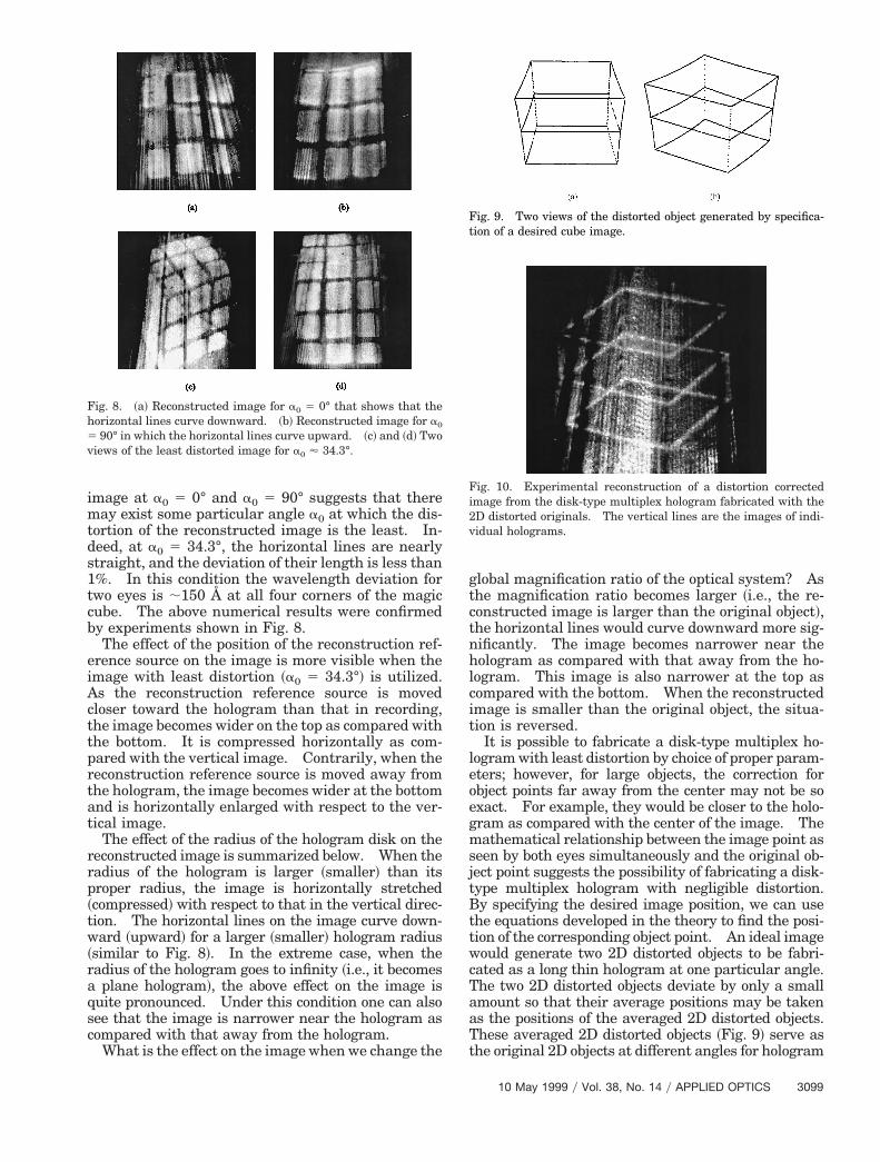
v
image at a0 5 0° and a0 5 90° suggests that theremay exist some particular angle a0 at which the dis-tortion of the reconstructed image is the least. In-deed, at a0 5 34.3°, the horizontal lines are nearlystraight, and the deviation of their length is less than1%. In this condition the wavelength deviation fortwo eyes is ;150 Å at all four corners of the magiccube. The above numerical results were confirmedby experiments shown in Fig. 8.
The effect of the position of the reconstruction ref-erence source on the image is more visible when theimage with least distortion ~a0 5 34.3°! is utilized.As the reconstruction reference source is movedcloser toward the hologram than that in recording,the image becomes wider on the top as compared withthe bottom. It is compressed horizontally as com-pared with the vertical image. Contrarily, when thereconstruction reference source is moved away fromthe hologram, the image becomes wider at the bottomand is horizontally enlarged with respect to the ver-tical image.
The effect of the radius of the hologram disk on thereconstructed image is summarized below. When theradius of the hologram is larger ~smaller! than itsproper radius, the image is horizontally stretched~compressed! with respect to that in the vertical direc-tion. The horizontal lines on the image curve down-ward ~upward! for a larger ~smaller! hologram radius~similar to Fig. 8!. In the extreme case, when theradius of the hologram goes to infinity ~i.e., it becomesa plane hologram!, the above effect on the image isquite pronounced. Under this condition one can alsosee that the image is narrower near the hologram ascompared with that away from the hologram.
What is the effect on the image when we change the
Fig. 8. ~a! Reconstructed image for a0 5 0° that shows that thehorizontal lines curve downward. ~b! Reconstructed image for a0
5 90° in which the horizontal lines curve upward. ~c! and ~d! Twoiews of the least distorted image for a0 ' 34.3°.
global magnification ratio of the optical system? Asthe magnification ratio becomes larger ~i.e., the re-constructed image is larger than the original object!,the horizontal lines would curve downward more sig-nificantly. The image becomes narrower near thehologram as compared with that away from the ho-logram. This image is also narrower at the top ascompared with the bottom. When the reconstructedimage is smaller than the original object, the situa-tion is reversed.
It is possible to fabricate a disk-type multiplex ho-logram with least distortion by choice of proper param-eters; however, for large objects, the correction forobject points far away from the center may not be soexact. For example, they would be closer to the holo-gram as compared with the center of the image. Themathematical relationship between the image point asseen by both eyes simultaneously and the original ob-ject point suggests the possibility of fabricating a disk-type multiplex hologram with negligible distortion.By specifying the desired image position, we can usethe equations developed in the theory to find the posi-tion of the corresponding object point. An ideal imagewould generate two 2D distorted objects to be fabri-cated as a long thin hologram at one particular angle.The two 2D distorted objects deviate by only a smallamount so that their average positions may be takenas the positions of the averaged 2D distorted objects.These averaged 2D distorted objects ~Fig. 9! serve asthe original 2D objects at different angles for hologram
Fig. 9. Two views of the distorted object generated by specifica-tion of a desired cube image.
Fig. 10. Experimental reconstruction of a distortion correctedimage from the disk-type multiplex hologram fabricated with the2D distorted originals. The vertical lines are the images of indi-vidual holograms.
10 May 1999 y Vol. 38, No. 14 y APPLIED OPTICS 3099

viifrhotfatmBdtTeosepbtphpvlspsettbiedihg
spsdato
3
fabrication. Figure 10 shows the experimentally re-constructed image of a cube by use of this method.Finally, we note that this method is feasible for a widerange of viewing angles at the object ~not limited to theangle a0 5 34.3°!.
4. Conclusion
On the basis of the coordinate rotation and simpleimaging relationship, the image ~on the detector! of apoint on a 3D object can be found for any particularCCD angle. This image is then transmitted to ananamorphic optical system ~Fig. 2! that images theertical image onto the holographic film plane whilet produces the image horizontally at the horizontalmage plane. The illuminating light source is trans-ormed into a horizontal line ~as the viewing slit forainbow hologram! behind the hologram plane. Theorizontal image and the vertical image of the pointbject as well as the line image of the source definehe incident ray direction at the hologram plane. Aan-shaped long thin slit is used to limit the recordingrea of an individual hologram so that it is a strip ofhe same shape. Each hologram records the infor-ation of a 2D photograph taken by the CCD camera.etween each recording the object and the hologramisk are rotated by the same small amount of anglehat corresponds to the width of the limiting slit.he information about the point object under consid-ration is recorded at the position of its vertical imagen the hologram. With illumination by the recon-truction reference source this information is regen-rated. As this hologram strip is rotated to aarticular angle d, the image of this object point cane seen by one of the eyes. Similarly, the informa-ion of this object point that belongs to a differenthotograph can be seen by the other eye when theologram is rotated to the reversed direction at someroper angle. Two eyes and the corresponding twoertical images on the proper holograms form twoines that then define the 3D position of the imageeen by the observer. The position of the imageoint for any object point can be calculated by theame equation set. Hence image distortion can bevaluated by calculation of the relative positions of allhe image points. Meanwhile, for each image point,he wavelength as seen by an individual eye can alsoe calculated. If we reverse the process by specify-ng a desired image, then through the same set ofquations the distorted 2D image of the objects atifferent viewing angles can be generated. By send-ng these 2D images into the input plane of theologram-forming system ~Fig. 2! we were able toenerate an image ~Fig. 9! with distortion correction.The theory developed was tested by both numerical
100 APPLIED OPTICS y Vol. 38, No. 14 y 10 May 1999
imulation and by experiment. The effects that de-end on the CCD angle, the position of the recon-truction reference source, the radius of the hologramisk, and the magnification ratio of the optical systemre described. At a different CCD angle, generally,he horizontal lines on the image curve either upwardr downward, except for a0 5 34.3° at which the
image exhibits least distortion. Each image pointobserved by different eyes is due to different wave-lengths, except for the image point at the center of theimage. When the reconstruction reference source ismoved closer to ~farther from! the hologram, the im-age is compressed ~enlarged! in the horizontal direc-tion with respect to the vertical direction. Becausethe radius of the hologram is larger ~smaller! than itsproper radius, the image is horizontally stretched~compressed!. When the magnification ratio be-comes larger ~smaller! so that the image is larger(smaller) than the original object, the image near thehologram or at the top is narrower ~wider! and iscompressed as compared with that away from thehologram or at the bottom. All the above variationsgenerally introduce different degrees of distortions tothe image. Finally, we note that although the fab-rication of a distortion-free disk-type multiplex holo-gram is feasible, more study is needed in order tofully understand the characteristics of this hologramunder generalized experimental parameters.
We thank the National Science Council for finan-cial support through grant NSC-86-2215-E-008-011.This study was presented at the 1997 OSA AnnualMeeting, Long Beach, California.
References1. S. A. Benton, “Hologram reconstruction with extended incoher-
ent sources,” J. Opt. Soc. Am. 59, 1545–1546 ~1969!.2. G. Saxby, Practical Holography, 2nd ed. ~Prentice-Hall, New
York, 1994!, pp. 308–311.3. L. Huff and R. L. Fusek, “Color holographic stereograms,” Opt.
Eng. 19, 691–695 ~1980!.4. E. N. Leith and P. Voulgaris, “Multiplex holography: some
new methods,” Opt. Eng. 24, 171–175 ~1985!.5. N. Ohyama, Y. Minami, A. Watanabe, J. Tsujiuchi, and T.
Honda, “Multiplex holograms of a skull made of CT images,”Opt. Commun. 61, 96–99 ~1987!.
6. S. A. Benton, “Alcove holograms for computer-aided design,” inTrue Three-Dimensional Imaging Techniques and DisplayTechnologies, D. F. McAllister and W. E. Robbins, eds., Proc.SPIE 761, 1–9 ~1987!.
7. K. Okada, S. Yoshii, Y. Yamaji, and J. Tsujiuchi, “Conical ho-lographic stereograms,” Opt. Commun. 73, 347–350 ~1989!.
8. L. M. Murillo-Mora, K. Okada, T. Honda, and J. Tsujiuchi,“Color conical holographic stereogram,” Opt. Eng. 34, 814–817~1995!.