Embed Size (px)
Citation preview
Discussion of the Use ofTransfer Grilles toFacilitate Return Air Flowin Central Return SystemsBuilding America Report - 00062000Armin Rudd
Abstract:
Transfer grilles represent a cost-effective alternative to individual return ducts if they are properly
configured for air flow, privacy, and aesthetics.
building science.com© 2008 Building Science Press All rights of reproduction in any form reserved.
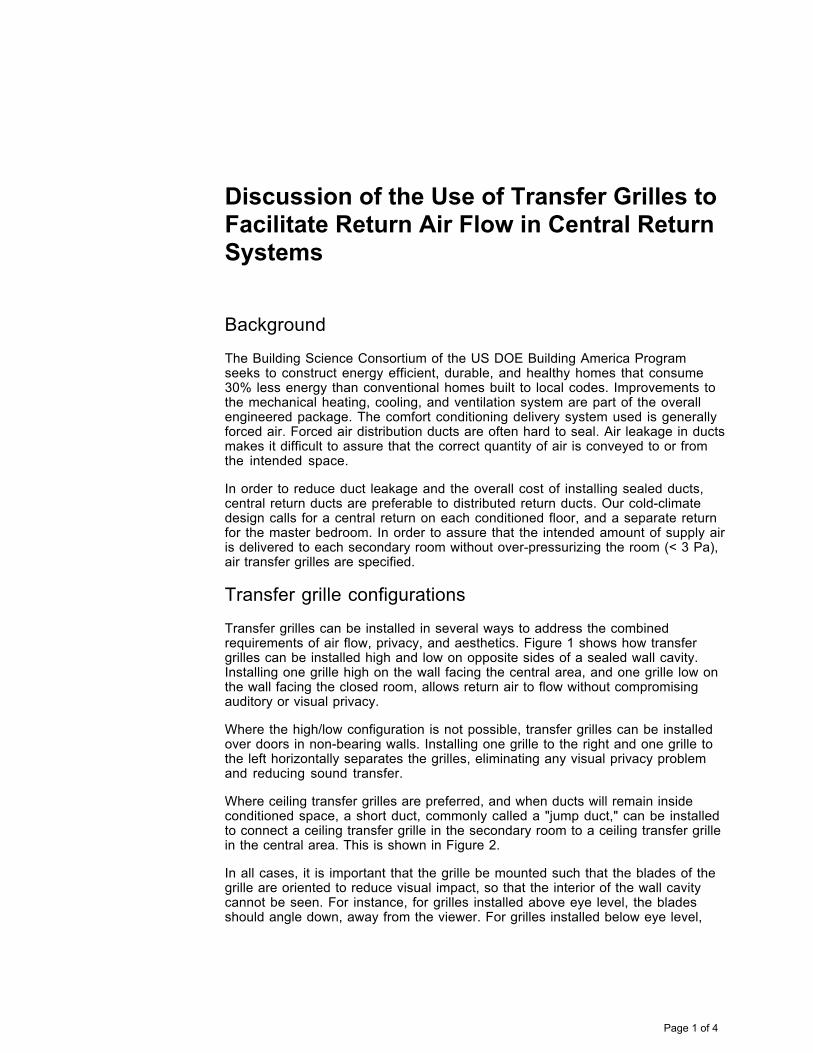
Discussion of the Use of Transfer Grilles to Facilitate Return Air Flow in Central ReturnSystems
Background
The Building Science Consortium of the US DOE Building America Programseeks to construct energy efficient, durable, and healthy homes that consume30% less energy than conventional homes built to local codes. Improvements tothe mechanical heating, cooling, and ventilation system are part of the overallengineered package. The comfort conditioning delivery system used is generallyforced air. Forced air distribution ducts are often hard to seal. Air leakage in ductsmakes it difficult to assure that the correct quantity of air is conveyed to or fromthe intended space.
In order to reduce duct leakage and the overall cost of installing sealed ducts,central return ducts are preferable to distributed return ducts. Our cold-climatedesign calls for a central return on each conditioned floor, and a separate returnfor the master bedroom. In order to assure that the intended amount of supply airis delivered to each secondary room without over-pressurizing the room (< 3 Pa),air transfer grilles are specified.
Transfer grille configurations
Transfer grilles can be installed in several ways to address the combinedrequirements of air flow, privacy, and aesthetics. Figure 1 shows how transfergrilles can be installed high and low on opposite sides of a sealed wall cavity.Installing one grille high on the wall facing the central area, and one grille low onthe wall facing the closed room, allows return air to flow without compromisingauditory or visual privacy.
Where the high/low configuration is not possible, transfer grilles can be installedover doors in non-bearing walls. Installing one grille to the right and one grille tothe left horizontally separates the grilles, eliminating any visual privacy problemand reducing sound transfer.
Where ceiling transfer grilles are preferred, and when ducts will remain insideconditioned space, a short duct, commonly called a "jump duct," can be installedto connect a ceiling transfer grille in the secondary room to a ceiling transfer grillein the central area. This is shown in Figure 2.
In all cases, it is important that the grille be mounted such that the blades of thegrille are oriented to reduce visual impact, so that the interior of the wall cavitycannot be seen. For instance, for grilles installed above eye level, the bladesshould angle down, away from the viewer. For grilles installed below eye level,
Page 1 of 4
the blades should angle upward away from the viewer. Grilles with longer curvedblades and a one-way air flow pattern are preferable to those with short straightblades. See the brief list at the end of some suitable grilles.
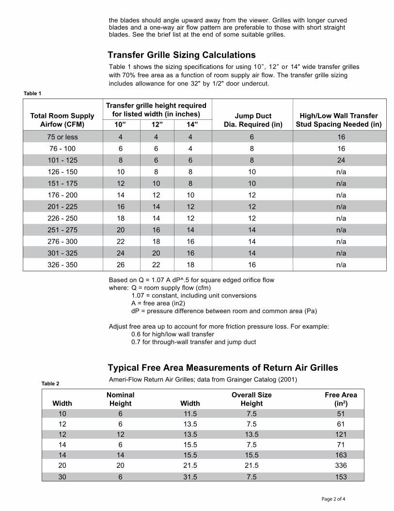
Transfer Grille Sizing CalculationsTable 1 shows the sizing specifications for using 10”, 12” or 14" wide transfer grilleswith 70% free area as a function of room supply air flow. The transfer grille sizingincludes allowance for one 32" by 1/2" door undercut.
Based on Q = 1.07 A dP^.5 for square edged orifice flowwhere: Q = room supply flow (cfm) 1.07 = constant, including unit conversions A = free area (in2) dP = pressure difference between room and common area (Pa)
Adjust free area up to account for more friction pressure loss. For example: 0.6 for high/low wall transfer 0.7 for through-wall transfer and jump duct
Page 2 of 4
75 or less 4 4 4 6 16 76 - 100 6 6 4 8 16 101 - 125 8 6 6 8 24 126 - 150 10 8 8 10 n/a 151 - 175 12 10 8 10 n/a 176 - 200 14 12 10 12 n/a 201 - 225 16 14 12 12 n/a 226 - 250 18 14 12 12 n/a 251 - 275 20 16 14 14 n/a 276 - 300 22 18 16 14 n/a 301 - 325 24 20 16 14 n/a 326 - 350 26 22 18 16 n/a
Total Room SupplyAirfow (CFM)
Transfer grille height requiredfor listed width (in inches)10” 12” 14”
Jump DuctDia. Required (in)
High/Low Wall TransferStud Spacing Needed (in)
Nominal Overall Size Free Area Width Height Width Height (in2) 10 6 11.5 7.5 51 12 6 13.5 7.5 61 12 12 13.5 13.5 121 14 6 15.5 7.5 71 14 14 15.5 15.5 163 20 20 21.5 21.5 336 30 6 31.5 7.5 153
Typical Free Area Measurements of Return Air GrillesAmeri-Flow Return Air Grilles; data from Grainger Catalog (2001)
Table 1
Table 2
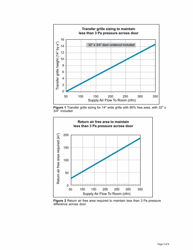
Figure 1 Transfer grille sizing for 14" wide grille with 80% free area, with 32" x3/4" included
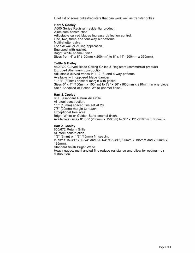
Figure 2 Return air free area required to maintain less than 3 Pa pressuredifference across door
Page 3 of 4
Transfer grille sizing to maintainless than 3 Pa pressure across door
Supply Air Flow To Room (cfm)
Tran
sfer
gril
le h
eigh
t (14
” by
x”)
50 100 150 200 250 300 350
16
14
12
10
8
6
4
2
0
32” x 3/4” door undercut included
Return air free area to maintainless than 3 Pa pressure across door
Supply Air Flow To Room (cfm)
Ret
urn
air f
ree
area
requ
ired
(in2 )
50 100 150 200 250 300 350
200
150
100
50
0
Adjustable curved blades increase deflection control.One, two, three and four-way air patterns.Multi-shutter valve.For sidewall or ceiling application.Equipped with gasket.Bright White enamel finish.Sizes from 4" x 8" (100mm x 200mm) to 8" x 14" (200mm x 350mm).
Tuttle & BaileyA40/A20 Curved Blade Ceiling Grilles & Registers (commercial product)Extruded Aluminum construction.Adjustable curved vanes in 1, 2, 3, and 4-way patterns.Available with opposed blade damper.1 -1/4" (30mm) nominal margin with gasket.Sizes 6" x 4" (150mm x 100mm) to 72" x 36" (1830mm x 910mm) in one pieceSatin Anodized or Baked White enamel finish.
Hart & Cooley657 Baseboard Return Air GrilleAll steel construction.1/3" (10mm) spaced fins set at 20.7/8" (20mm) margin turnback.Exceptional free area.Bright White or Golden Sand enamel finish.Available in sizes 8" x 6" (200mm x 150mm) to 36" x 12" (910mm x 300mm).
Hart & Cooley650/672 Return GrilleAll steel construction.1/3" (8mm) or 1/2" (10mm) fin spacing.In sizes 15-3/4" x 7-3/4" and 31-1/4" x 7-3/4"(395mm x 195mm and 780mm x195mm).Standard finish Bright White.Heavy-gauge, multi-angled fins reduce resistance and allow for optimum airdistribution.
Page 4 of 4
Brief list of some grilles/registers that can work well as transfer grilles
Hart & CooleyA600 Series Register (residential product)Aluminum construction.
Building Science Corporation Transfer Grille Details Page 1 of 2
Building Science Corporation
Transfer Grille From Builder’s Guide, Building Science Corporation • All supply registers should have clear access to a return grille in order to prevent the pressurization
of bedrooms and depressurization of the common area. Bedrooms should either have hard-ducted returns, or another means of pressure relief, such as transfer grilles (above) or jump ducts (below).
• Maximum that can be returned by through-the-wall hi-low transfer grille is ~125 CFM, assuming door undercut.
• Door undercut of 1” minimum still required • Pressurization is especially severe when combining oversized air handlers (e.g., 5 tons in 2000 sf)
and large master bedroom suites that can be sealed from the main space with one door. Undercutting the door seldom provides adequate pressure relief.
• Refer to Transfer Grille Sizing Table to compute required free area (and grille size) vs. supply airflow.
© buildingscience.com
Building Science Corporation Transfer Grille Details Page 2 of 2
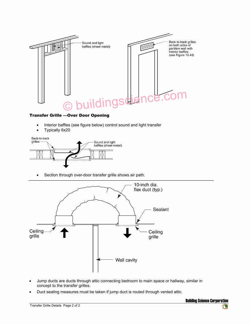
Transfer Grille —Over Door Opening
• Interior baffles (see figure below) control sound and light transfer • Typically 6x20
• Section through over-door transfer grille shows air path.
• Jump ducts are ducts through attic connecting bedroom to main space or hallway, similar in
concept to the transfer grilles. • Duct sealing measures must be taken if jump duct is routed through vented attic.
© buildingscience.com
Discussion of the Use of Transfer Grilles to Facilitate Return Air Flow in Central Return Systems
About this Report
This report was produced in cooperation with the Building America Program.
About the Author
Armin Rudd is a principal engineer at Building Science Corporation in Westford,Massachusetts. More information about Armin Rudd can be found at
www.buildingscienceconsulting.com.
Direct all correspondence to: Building Science Corporation, 30 Forest Street,Somerville, MA 02143.
Limits of Liability and Disclaimer of Warranty:
Building Science documents are intended for professionals. The author and the publisher of this article have used their best efforts toprovide accurate and authoritative information in regard to the subject matter covered. The author and publisher make no warranty ofany kind, expressed or implied, with regard to the information contained in this article.
The information presented in this article must be used with care by professionals who understand the implications of what they aredoing. If professional advice or other expert assistance is required, the services of a competent professional shall be sought. The authorand publisher shall not be liable in the event of incidental or consequential damages in connection with, or arising from, the use of theinformation contained within this Building Science document.