Embed Size (px)
Citation preview
DISCRETE CAMERA AUTOCALIBRATION CONSISTENT WITHTHE FRAME OF THE ROBOTIC PAN-TILT BASIS
R. Galego1, R. Ferreira1, A. Bernardino1, E. Grossmann2, J. Gaspar11ISR, Instituto Superior Tecnico, Lisboa, Portugal
2Intel Corp., Menlo Park, USArgalego,ricardo,alex,[email protected], [email protected]
Keywords: Sensor topology, Multidimensional scaling (MDS), Isomap.
Abstract: In this paper we approach the problem of calibrating topologically a discretecamera mounted on a roboticpan-tilt basis. In particular this work is focused in choosing the coordinatesystem of the camera consistentlywith the basis. The topological calibrating methodology of the sensor is based on multidimensional scaling(MDS). The choice of the coordinate system is based in performing known pan and tilt movements with therobotic basis. These movements allow estimating the arbitrary unitary transformation introduced by MDS likealgorithms, and therefore compensate image rotation and vertical or horizontal mirroring. Given a consistentcamera coordinate system and the odometry of the robotic basis during thecapture of sequence of images,allows building image mosaics with discrete cameras.
1 Introduction
Traditional imaging sensors are formed by pixelsprecisely placed in a rectangular grid, and thus looklike calibrated sensors for many practical purposessuch as localizing image edges or corners. In contrast,the most common imaging sensors found in nature arethe compound eyes, collections of individual photocells which clearly do not form rectangular grids, butare still interesting to mimic as they are very effectivein solving various tasks at hand.
In the cases where the sensor topology is not arectangular grid, one can not use traditional calibra-tion methodologies [1, 12, 10, 7]. Despite not formingin general regular grids, recent works show that com-pound imaging systems, i.e. discrete cameras, can beautocalibrated. In the seminal work [8] Pierce andKuipers have shown that is possible to reconstruct thetopology of a group of sensors just by knowing theiroutput. Grossmannet al. [5] shown that the func-tion relating signal-correlation and distance-angles ofthe photosensors of a camera can help calibrating an-other camera. Recently Galegoet al. [6] proposeda methodology to autocalibrate a central imaging sen-sor which is effective even without a priori calibrationinformation.
In this work we want to do auto-calibration of cen-tral sensors with a number of pixels orders of mag-nitude larger than [5]. In addition, we assume thatthe sensors are mounted on robotic pan-tilt basis, andtherefore want the camera to have a reference frameconsistent with (linked to) the reference frame of thebasis. We approach the computational complexitywith Multi Dimensional Scaling (MDS) like algo-rithms [2, 11, 9]. Classical MDS [2] allows findinga representation of a data set on a given dimension-ality from the knowledge of all interpoint Euclideandistances. We approach the problem of matching ref-erence frames by performing pan-tilt movements withthe robotic basis and observing the flow in the topo-logically calibrated camera. The flow vectors allowcomputing a unitary transformation which matchesthe camera and the basis frames.
The structure of the paper is the following: inSec.2 we describe camera model; in Sec.3 we de-scribe MDS/Isomap applied to topological calibra-tion; in Sec.4 is proposed a rotation and/or mirroringcorrection methodology for the coordinate frame ofthe imaging sensor; in Sec.5 summarizes the completecalibration methodology; in Sec.6 we show some ex-perimental results, and finally in Sec.7 we draw someconclusions and propose some future work.
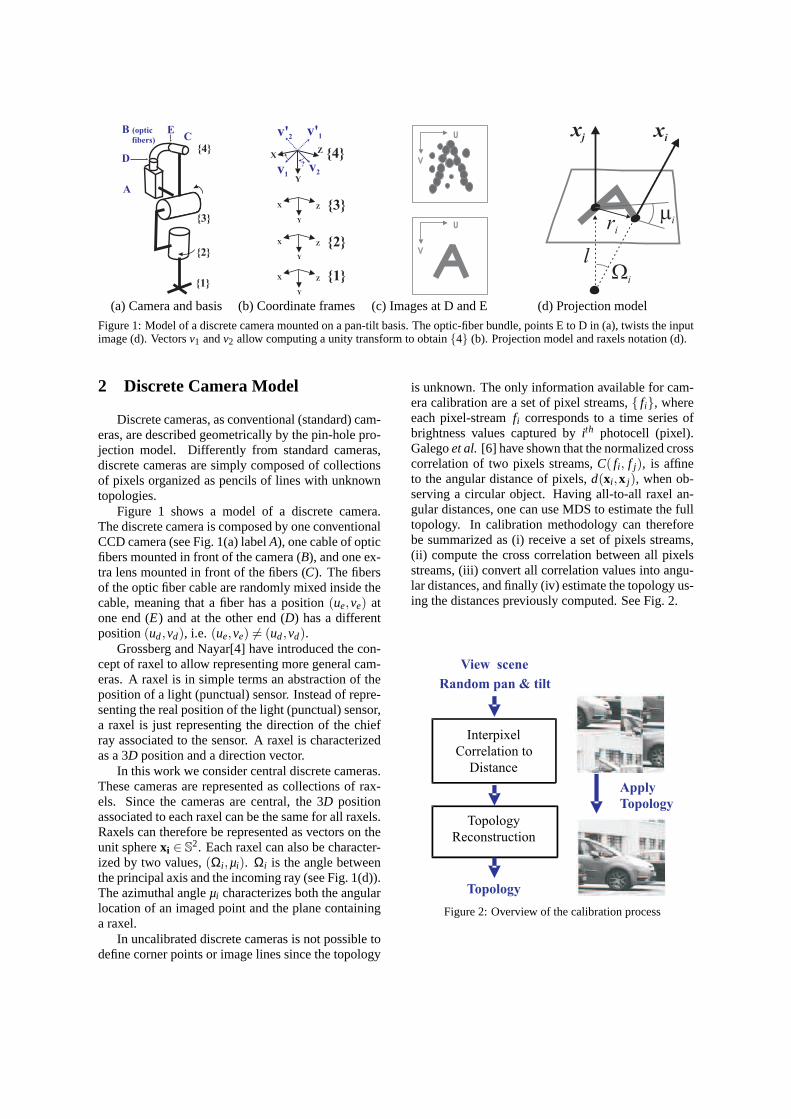
(a) Camera and basis (b) Coordinate frames (c) Images at D andE (d) Projection model
Figure 1: Model of a discrete camera mounted on a pan-tilt basis. The optic-fiber bundle, points E to D in (a), twists the inputimage (d). Vectorsv1 andv2 allow computing a unity transform to obtain4 (b). Projection model and raxels notation (d).
2 Discrete Camera Model
Discrete cameras, as conventional (standard) cam-eras, are described geometrically by the pin-hole pro-jection model. Differently from standard cameras,discrete cameras are simply composed of collectionsof pixels organized as pencils of lines with unknowntopologies.
Figure 1 shows a model of a discrete camera.The discrete camera is composed by one conventionalCCD camera (see Fig. 1(a) labelA), one cable of opticfibers mounted in front of the camera (B), and one ex-tra lens mounted in front of the fibers (C). The fibersof the optic fiber cable are randomly mixed inside thecable, meaning that a fiber has a position(ue,ve) atone end (E) and at the other end (D) has a differentposition(ud,vd), i.e. (ue,ve) 6= (ud,vd).
Grossberg and Nayar[4] have introduced the con-cept of raxel to allow representing more general cam-eras. A raxel is in simple terms an abstraction of theposition of a light (punctual) sensor. Instead of repre-senting the real position of the light (punctual) sensor,a raxel is just representing the direction of the chiefray associated to the sensor. A raxel is characterizedas a 3D position and a direction vector.
In this work we consider central discrete cameras.These cameras are represented as collections of rax-els. Since the cameras are central, the 3D positionassociated to each raxel can be the same for all raxels.Raxels can therefore be represented as vectors on theunit spherexi ∈ S
2. Each raxel can also be character-ized by two values,(Ωi ,µi). Ωi is the angle betweenthe principal axis and the incoming ray (see Fig. 1(d)).The azimuthal angleµi characterizes both the angularlocation of an imaged point and the plane containinga raxel.
In uncalibrated discrete cameras is not possible todefine corner points or image lines since the topology
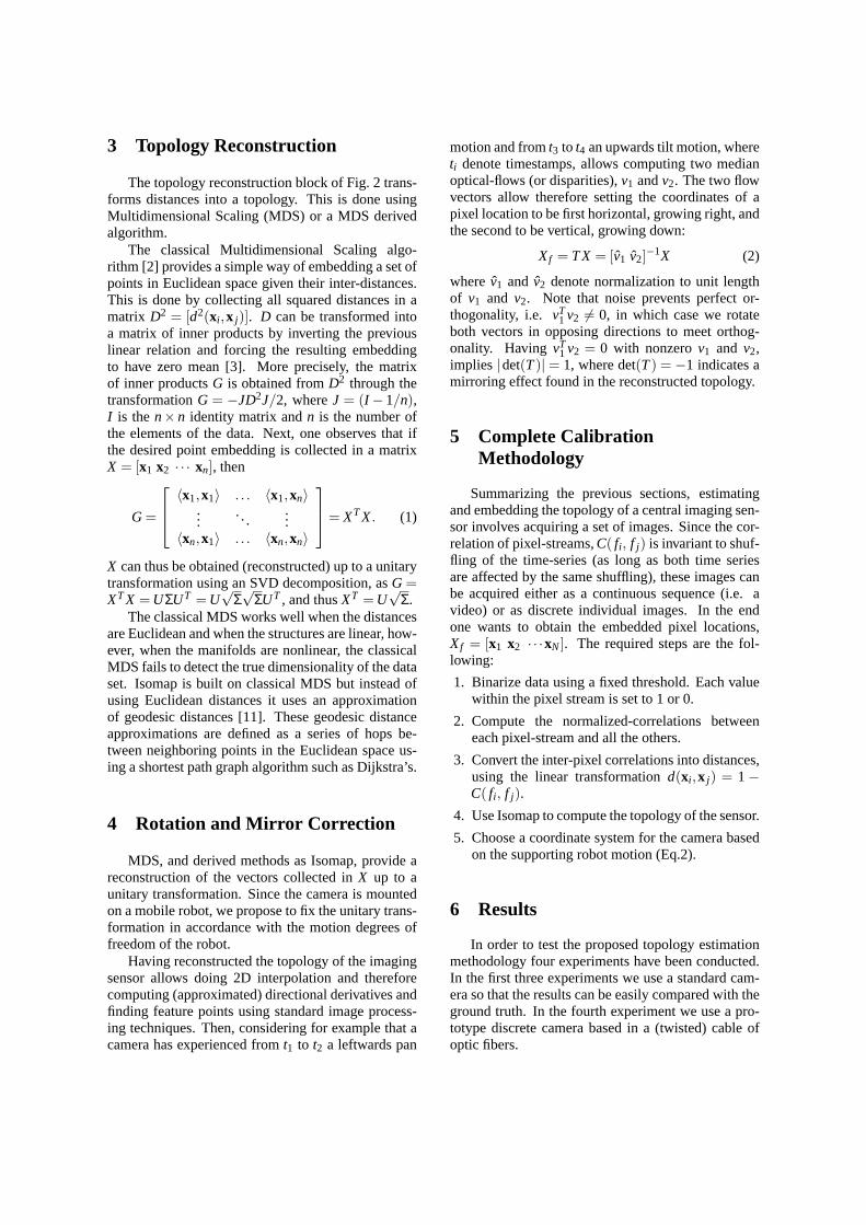
is unknown. The only information available for cam-era calibration are a set of pixel streams, fi, whereeach pixel-streamfi corresponds to a time series ofbrightness values captured byith photocell (pixel).Galegoet al. [6] have shown that the normalized crosscorrelation of two pixels streams,C( fi , f j), is affineto the angular distance of pixels,d(xi ,x j), when ob-serving a circular object. Having all-to-all raxel an-gular distances, one can use MDS to estimate the fulltopology. In calibration methodology can thereforebe summarized as (i) receive a set of pixels streams,(ii) compute the cross correlation between all pixelsstreams, (iii) convert all correlation values into angu-lar distances, and finally (iv) estimate the topology us-ing the distances previously computed. See Fig. 2.
View scene
Random pan & tilt
Topology
Reconstruction
Interpixel
Correlation to
Distance
Topology
Apply
Topology
Figure 2: Overview of the calibration process
3 Topology Reconstruction
The topology reconstruction block of Fig. 2 trans-forms distances into a topology. This is done usingMultidimensional Scaling (MDS) or a MDS derivedalgorithm.
The classical Multidimensional Scaling algo-rithm [2] provides a simple way of embedding a set ofpoints in Euclidean space given their inter-distances.This is done by collecting all squared distances in amatrix D2 = [d2(xi ,x j)]. D can be transformed intoa matrix of inner products by inverting the previouslinear relation and forcing the resulting embeddingto have zero mean [3]. More precisely, the matrixof inner productsG is obtained fromD2 through thetransformationG = −JD2J/2, whereJ = (I − 1/n),I is then× n identity matrix andn is the number ofthe elements of the data. Next, one observes that ifthe desired point embedding is collected in a matrixX = [x1 x2 · · · xn], then
G=
〈x1,x1〉 . . . 〈x1,xn〉...
. . ....
〈xn,x1〉 . . . 〈xn,xn〉
= XTX. (1)
X can thus be obtained (reconstructed) up to a unitarytransformation using an SVD decomposition, asG=XTX =UΣUT =U
√Σ√
ΣUT , and thusXT =U√
Σ.The classical MDS works well when the distances
are Euclidean and when the structures are linear, how-ever, when the manifolds are nonlinear, the classicalMDS fails to detect the true dimensionality of the dataset. Isomap is built on classical MDS but instead ofusing Euclidean distances it uses an approximationof geodesic distances [11]. These geodesic distanceapproximations are defined as a series of hops be-tween neighboring points in the Euclidean space us-ing a shortest path graph algorithm such as Dijkstra’s.
4 Rotation and Mirror Correction
MDS, and derived methods as Isomap, provide areconstruction of the vectors collected inX up to aunitary transformation. Since the camera is mountedon a mobile robot, we propose to fix the unitary trans-formation in accordance with the motion degrees offreedom of the robot.
Having reconstructed the topology of the imagingsensor allows doing 2D interpolation and thereforecomputing (approximated) directional derivatives andfinding feature points using standard image process-ing techniques. Then, considering for example that acamera has experienced fromt1 to t2 a leftwards pan
motion and fromt3 to t4 an upwards tilt motion, whereti denote timestamps, allows computing two medianoptical-flows (or disparities),v1 andv2. The two flowvectors allow therefore setting the coordinates of apixel location to be first horizontal, growing right, andthe second to be vertical, growing down:
Xf = TX = [v1 v2]−1X (2)
wherev1 and v2 denote normalization to unit lengthof v1 and v2. Note that noise prevents perfect or-thogonality, i.e. vT
1 v2 6= 0, in which case we rotateboth vectors in opposing directions to meet orthog-onality. HavingvT
1 v2 = 0 with nonzerov1 and v2,implies |det(T)| = 1, where det(T) = −1 indicates amirroring effect found in the reconstructed topology.
5 Complete CalibrationMethodology
Summarizing the previous sections, estimatingand embedding the topology of a central imaging sen-sor involves acquiring a set of images. Since the cor-relation of pixel-streams,C( fi , f j) is invariant to shuf-fling of the time-series (as long as both time seriesare affected by the same shuffling), these images canbe acquired either as a continuous sequence (i.e. avideo) or as discrete individual images. In the endone wants to obtain the embedded pixel locations,Xf = [x1 x2 · · ·xN]. The required steps are the fol-lowing:
1. Binarize data using a fixed threshold. Each valuewithin the pixel stream is set to 1 or 0.
2. Compute the normalized-correlations betweeneach pixel-stream and all the others.
3. Convert the inter-pixel correlations into distances,using the linear transformationd(xi ,x j) = 1−C( fi , f j).
4. Use Isomap to compute the topology of the sensor.
5. Choose a coordinate system for the camera basedon the supporting robot motion (Eq.2).
6 Results
In order to test the proposed topology estimationmethodology four experiments have been conducted.In the first three experiments we use a standard cam-era so that the results can be easily compared with theground truth. In the fourth experiment we use a pro-totype discrete camera based in a (twisted) cable ofoptic fibers.
(a) Test image (b) 2×4permutation
(c) 2×4permutation
(d) 10×10permutation
(e) 100×100permutation
(f) 1 of 14784calibration
images
(g) 100×100permutation
(h) 3 of 1002
pixel streams(i) Topology found (j) Topology found rotated
(Eq.2), bottom left zoomed
(k) Reconstructionafter 2×4 permutation
(l) Reconstruction after10×10 permutation
(m) Reconstruction after100×100 permutation
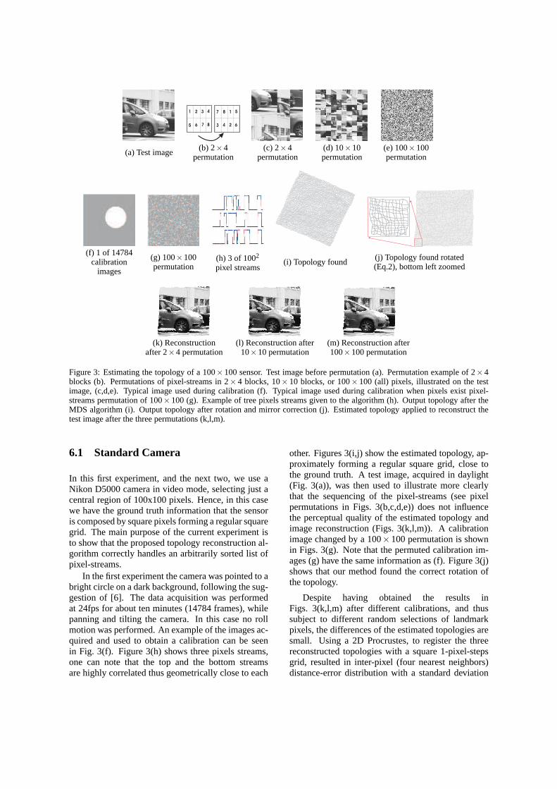
Figure 3: Estimating the topology of a 100×100 sensor. Test image before permutation (a). Permutation example of 2×4blocks (b). Permutations of pixel-streams in 2× 4 blocks, 10× 10 blocks, or 100× 100 (all) pixels, illustrated on the testimage, (c,d,e). Typical image used during calibration (f). Typical image used during calibration when pixels exist pixel-streams permutation of 100×100 (g). Example of tree pixels streams given to the algorithm (h). Outputtopology after theMDS algorithm (i). Output topology after rotation and mirror correction (j).Estimated topology applied to reconstruct thetest image after the three permutations (k,l,m).
6.1 Standard Camera
In this first experiment, and the next two, we use aNikon D5000 camera in video mode, selecting just acentral region of 100x100 pixels. Hence, in this casewe have the ground truth information that the sensoris composed by square pixels forming a regular squaregrid. The main purpose of the current experiment isto show that the proposed topology reconstruction al-gorithm correctly handles an arbitrarily sorted list ofpixel-streams.
In the first experiment the camera was pointed to abright circle on a dark background, following the sug-gestion of [6]. The data acquisition was performedat 24fps for about ten minutes (14784 frames), whilepanning and tilting the camera. In this case no rollmotion was performed. An example of the images ac-quired and used to obtain a calibration can be seenin Fig. 3(f). Figure 3(h) shows three pixels streams,one can note that the top and the bottom streamsare highly correlated thus geometrically close to each
other. Figures 3(i,j) show the estimated topology, ap-proximately forming a regular square grid, close tothe ground truth. A test image, acquired in daylight(Fig. 3(a)), was then used to illustrate more clearlythat the sequencing of the pixel-streams (see pixelpermutations in Figs. 3(b,c,d,e)) does not influencethe perceptual quality of the estimated topology andimage reconstruction (Figs. 3(k,l,m)). A calibrationimage changed by a 100×100 permutation is shownin Figs. 3(g). Note that the permuted calibration im-ages (g) have the same information as (f). Figure 3(j)shows that our method found the correct rotation ofthe topology.
Despite having obtained the results inFigs. 3(k,l,m) after different calibrations, and thussubject to different random selections of landmarkpixels, the differences of the estimated topologies aresmall. Using a 2D Procrustes, to register the threereconstructed topologies with a square 1-pixel-stepsgrid, resulted in inter-pixel (four nearest neighbors)distance-error distribution with a standard deviation
of 0.566, 0.563 and 0.563 pixels, respectively.
6.2 Mirror Effect Correction
(a) (b) (c)
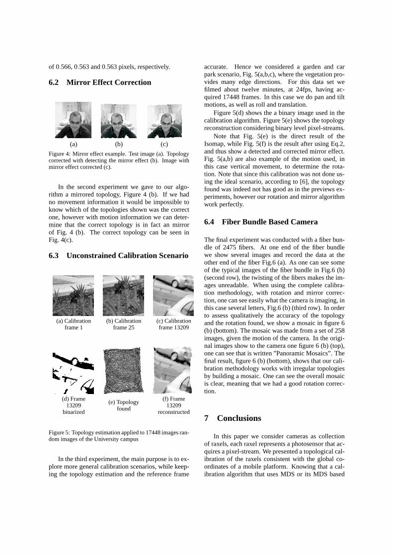
Figure 4: Mirror effect example. Test image (a). Topologycorrected with detecting the mirror effect (b). Image withmirror effect corrected (c).
In the second experiment we gave to our algo-rithm a mirrored topology, Figure 4 (b). If we hadno movement information it would be impossible toknow which of the topologies shown was the correctone, however with motion information we can deter-mine that the correct topology is in fact an mirrorof Fig. 4 (b). The correct topology can be seen inFig. 4(c).
6.3 Unconstrained Calibration Scenario
(a) Calibrationframe 1
(b) Calibrationframe 25
(c) Calibrationframe 13209
(d) Frame13209
binarized
(e) Topologyfound
(f) Frame13209
reconstructed
Figure 5: Topology estimation applied to 17448 images ran-dom images of the University campus
In the third experiment, the main purpose is to ex-plore more general calibration scenarios, while keep-ing the topology estimation and the reference frame
accurate. Hence we considered a garden and carpark scenario, Fig. 5(a,b,c), where the vegetation pro-vides many edge directions. For this data set wefilmed about twelve minutes, at 24fps, having ac-quired 17448 frames. In this case we do pan and tiltmotions, as well as roll and translation.
Figure 5(d) shows the a binary image used in thecalibration algorithm. Figure 5(e) shows the topologyreconstruction considering binary level pixel-streams.
Note that Fig. 5(e) is the direct result of theIsomap, while Fig. 5(f) is the result after using Eq.2,and thus show a detected and corrected mirror effect.Fig. 5(a,b) are also example of the motion used, inthis case vertical movement, to determine the rota-tion. Note that since this calibration was not done us-ing the ideal scenario, according to [6], the topologyfound was indeed not has good as in the previews ex-periments, however our rotation and mirror algorithmwork perfectly.
6.4 Fiber Bundle Based Camera
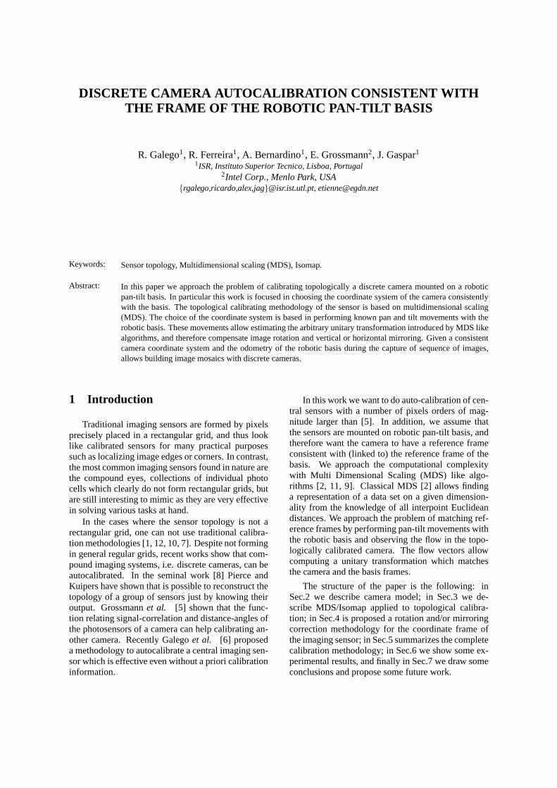
The final experiment was conducted with a fiber bun-dle of 2475 fibers. At one end of the fiber bundlewe show several images and record the data at theother end of the fiber Fig.6 (a). As one can see someof the typical images of the fiber bundle in Fig.6 (b)(second row), the twisting of the fibers makes the im-ages unreadable. When using the complete calibra-tion methodology, with rotation and mirror correc-tion, one can see easily what the camera is imaging, inthis case several letters, Fig.6 (b) (third row). In orderto assess qualitatively the accuracy of the topologyand the rotation found, we show a mosaic in figure 6(b) (bottom). The mosaic was made from a set of 258images, given the motion of the camera. In the origi-nal images show to the camera one figure 6 (b) (top),one can see that is written ”Panoramic Mosaics”. Thefinal result, figure 6 (b) (bottom), shows that our cali-bration methodology works with irregular topologiesby building a mosaic. One can see the overall mosaicis clear, meaning that we had a good rotation correc-tion.
7 Conclusions
In this paper we consider cameras as collectionof raxels, each raxel represents a photosensor that ac-quires a pixel-stream. We presented a topological cal-ibration of the raxels consistent with the global co-ordinates of a mobile platform. Knowing that a cal-ibration algorithm that uses MDS or its MDS based
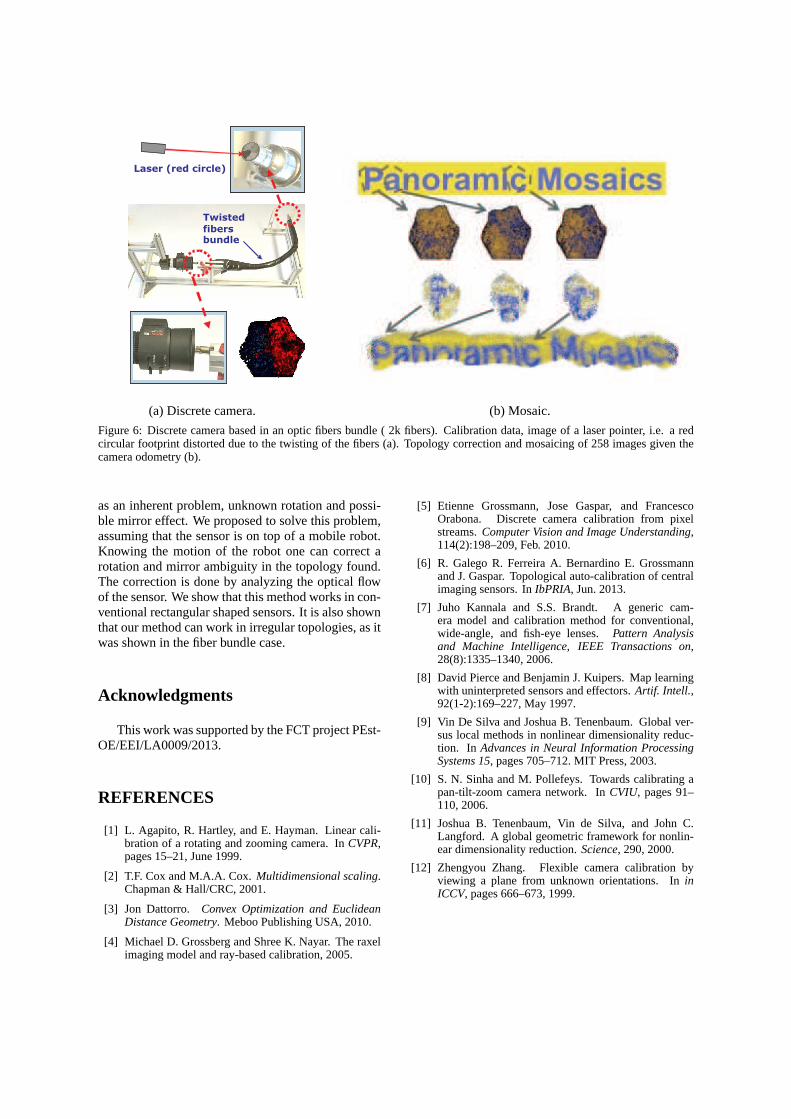
(a) Discrete camera. (b) Mosaic.
Figure 6: Discrete camera based in an optic fibers bundle ( 2k fibers). Calibration data, image of a laser pointer, i.e. a redcircular footprint distorted due to the twisting of the fibers (a). Topology correction and mosaicing of 258 images given thecamera odometry (b).
as an inherent problem, unknown rotation and possi-ble mirror effect. We proposed to solve this problem,assuming that the sensor is on top of a mobile robot.Knowing the motion of the robot one can correct arotation and mirror ambiguity in the topology found.The correction is done by analyzing the optical flowof the sensor. We show that this method works in con-ventional rectangular shaped sensors. It is also shownthat our method can work in irregular topologies, as itwas shown in the fiber bundle case.
Acknowledgments
This work was supported by the FCT project PEst-OE/EEI/LA0009/2013.
REFERENCES
[1] L. Agapito, R. Hartley, and E. Hayman. Linear cali-bration of a rotating and zooming camera. InCVPR,pages 15–21, June 1999.
[2] T.F. Cox and M.A.A. Cox.Multidimensional scaling.Chapman & Hall/CRC, 2001.
[3] Jon Dattorro. Convex Optimization and EuclideanDistance Geometry. Meboo Publishing USA, 2010.
[4] Michael D. Grossberg and Shree K. Nayar. The raxelimaging model and ray-based calibration, 2005.
[5] Etienne Grossmann, Jose Gaspar, and FrancescoOrabona. Discrete camera calibration from pixelstreams.Computer Vision and Image Understanding,114(2):198–209, Feb. 2010.
[6] R. Galego R. Ferreira A. Bernardino E. Grossmannand J. Gaspar. Topological auto-calibration of centralimaging sensors. InIbPRIA, Jun. 2013.
[7] Juho Kannala and S.S. Brandt. A generic cam-era model and calibration method for conventional,wide-angle, and fish-eye lenses.Pattern Analysisand Machine Intelligence, IEEE Transactions on,28(8):1335–1340, 2006.
[8] David Pierce and Benjamin J. Kuipers. Map learningwith uninterpreted sensors and effectors.Artif. Intell.,92(1-2):169–227, May 1997.
[9] Vin De Silva and Joshua B. Tenenbaum. Global ver-sus local methods in nonlinear dimensionality reduc-tion. In Advances in Neural Information ProcessingSystems 15, pages 705–712. MIT Press, 2003.
[10] S. N. Sinha and M. Pollefeys. Towards calibrating apan-tilt-zoom camera network. InCVIU, pages 91–110, 2006.
[11] Joshua B. Tenenbaum, Vin de Silva, and John C.Langford. A global geometric framework for nonlin-ear dimensionality reduction.Science, 290, 2000.
[12] Zhengyou Zhang. Flexible camera calibration byviewing a plane from unknown orientations. IninICCV, pages 666–673, 1999.