Embed Size (px)
Citation preview

Discover failure mechanism of a landslide dam using UAV
Kuo-Lung Wang1 and Zhi-Jie Huang2
1) Associate Professor, Department of Civil Engineering, National Chi Nan University, Nantou, Taiwan. Email:
[email protected] 2) Master, Department of Civil Engineering, National Chi Nan University, Nantou, Taiwan. Email: [email protected] Abstract:
Unmanned Aerial Vehicle (UAV) was developed very fast in recent years and budget to use UAV was reduced very fast. Thus the usage of UAV for investigation is becoming possible and using as a basic tool. Road Tai-14 at 74.5K is selected as study area in this research. A landslide dam was formed in 0610 heavy rain fall event in June, 2012. The landslide dam was collapsed in few hours and foundation of road was destroyed by erosion with fast water flow, which resulted in closed roads closed for several days. Current slope condition was analyzed from temporal satellite images, field investigation, and high resolution orhtophotos, high accuracy DSM from UAV. The result shows that the landslide dam in 2012 was formed from the landslide located at right bank of river. Moreover, the slope is still not stable and moving in 2014 without heavy rainfall event. More geological formation is discovering from high resolution orthophoto and DSM. The results show that the landslide was induced not only by rainfall but also geological structure failure. So continuous monitoring should be carried on in this study area. Keywords: UAV, landslide, orthophoto, PIV 1. INTRODUCTION
The study site, where is Ren-Tzu-Guam located central of Taiwan and a shaped sandstone canyon scenery cut by May river as shown in Figure 1. Sand rock in this area is stiff and formation almost vertical. According to fossil record by Hsieh(2011), the study is located at the bottom of Lushan formation. Landslide was occurred owing to heavy rainfall from 10 to 12, June, 2012. According to interview and police documentation, landslide dam was formed and flushed away in 2 hours in the morning of 12, June, 2012. Landslide located at 75k of Road Tai-14 and the road was blocked owing to one lane of the road was destroyed by landslide dam break. According to previous study of authors, the landslide dam event was sliding again form the rest of slide mass occurred in 2008 event, typhoon Sinlaku.
Figure 1. Location of study area
However, the geological formation of study site is slate, Lushan formation according to Wushe geological map (scale 1:50,000). Major geological bedding is N42E/80SE but also consists of N12E to N43E/ 10 to 25 SE cleavage. Bedding and cleavage interlayered horizontally and vertically during field investigation. The geological condition is squeezed and fractured with Meishi fault located nearby. Unmanned Aerial Vehicle (UAV) is adopted in this
1494

research to investigate the landslide. With rapid acquired orthophoto, digital surface model (DSM), digital elevation model (DEM), previous DEM from government, numerical simulation has been performed for slope stability analysis. The remain slope is also using PIV for landslide displacement analysis from image analysis. The results can support landslide hazard mitigation and engineering treatment. 2. METHOD
2.1 Introduction of Multi-rotor drone
UAV is widely used for remote control aircraft recent years. UAV was used for military purpose before but recently is used for city discovery, environment monitoring, landslide hazard mitigation and commercial photos. UAV can be divided into two major groups – fixed wing and multi-rotors. Fixed wing UAV can fly with strong wind and longer distance but a long taxiway is required for take-off and landing. Despite of poorly anti-wind, multi-rotor drones is more suitable for hazard site investigation with poor road condition. Thus multi-rotor drones are adopted in this research.
Multi-rotor drone used in this research is assembled by research team. The dimension of the drone is 60cm height, 96cm wide and weighted 6.8kg. Maximum payload is 2.5kg and hover time is about 25min. The maximum elevation is 500m above take-off ground elevation during test fly. 3-dimension axis force feedback cradle is mounted on the drone for steady shot of photos. Fly control of the drone is IMU-based open source ArduPilot Mega (APM) and Mission Planner (MP) ground station is adopted. The control system is followed GNU codes and layout, technical data, and source code is open on internet. Users can revise layout and codes for their own requirement.
The fly information such as fly height, yaw, roll, speed, location can transmit via radio such as xbee from drone to laptop, tablet, and mobile phone. The base map in MP can be Google Map, Bing Map, Open Street Map, and user defined map, etc. User can monitor UAV real time location on map and submit new flying task to UAV during fly. The hover can be automatic take-off, fly, and land by itself without manual control.
2.2 3-D reconstruction
GPS data of UAV can transmit to laptop during hover. The GPS logs can be written to photos taken from UAV after UAV landed. The fitting of GPS data to photos can help to improve processing time for photo alignment. Agisoft is selected for 3-D reconstruction. The location of photos can be shown on map and thus ground control point (GCP) can be selected from photos before or after alignment. Thus the 3-D point clouds, meshes, and tiles can be derived from photo alignment and collinear solutions. The mosaic photo and DSM can be generated and orhtophoto can be projected to user defined planes. The point clouds can be divided into different groups this DEM production is possible after processing.
2.3 Accuracy discussion
Owing to study site is located in mountainous area thus the natural GCPs are not easy to find. GCPs are set up to improve accuracy. The accuracy of GCPs are as illustrated in Table 1. The errors on GCPS are more than 8 meter even GPS is mounted on UAV. The main reason is the GPS is single frequency and the error is about accuracy margin. With the centimeter accuracy GCPS to solve ground points, the errors of GCPS can be reduced to less than 10cm in this research. The resolution of orthophoto is 5cm. Small cracks on slope is not easy to find with such resolution but is sufficient for displacement analysis and slope stability analysis.
Table 1. Accuracy comparison with and without GCP
GCP Point 1 Point 2 Point 3 Point 4
GCP elevation (m) 860.918 862.784 863.123 864.553
Without GCP (m) 852.313 853.995 854.335 855.745
Error (m) 8.605 8.789 8.788 8.803
With GCP (m) 860.835 862.776 863.104 864.454
Error (m) 0.083 0.008 0.019 0.099
3. RESULTS
3.1 PIV analysis
Location of landslide and displacement can be derived from Particle Image Velocimetry (PIV). The process of PIV is based on the correlation analysis of two images with search characteristic points between two images. The
1495

characteristic points are identified with FFT. The displacements can be calculated after IFFT of images. The process of PIV is as illustrated in Figure 2.
Figure 2. Process of PIV analysis (Raffel et al., 2007)
Two images produced in 20, Feb, 2014 and 9, Dec, 2014 are selected for PIV analysis. Each images are orthophotos with 5cm resolution. The sub area of landslide dam is selected for PIV analysis. The analysis can help to understand current condition of landslide, which is moving or not. The code for PIV analysis PIVTEC. Setting window for search is 64 by 64 pixels and moving windows is 32 by 32 pixels. The PIV analysis result is as shown in Figure 3. The scale locates at the upper left is 20cm and red color means larger displacement than green. As shown in Figure 3, the analysis baseline is 292 days with limited rainfall but some large displacement vectors are shown on the slope, especially bare surface condition. The displacement vectors are point toward down slope direction. Besides, there are no obvious displacement vectors existed on the main slope mass. Conclusions can be made to shallow sliding for current condition and major sliding remains stable during study period.
Figure 3. Result of PIV analysis with 20, Feb, 2014 in the background
3.2 Pre- and Post- Failure analysis
DEM with 5m resolution produced in July, 2004 and DEM with UAV are compared to identify sliding plane. The location for sliding profile is as shown in Figure 4. Main sliding direction is from north-west to south-east. Residual sliding mass is still located on the slope and bed rock is day light obviously. So the sliding plane can be determined accordingly. The reference coordinate system of 2004 DEM and 2014 DEM is different. Thus the profiles are fitted after derived from each DEM to correct reference height. The analysis code Rocscience/Slide and Phase 2 is adopted for limit equilibrium and deformation analysis. Duncan et al. (2008) used the same code for embankment
1496

stability analysis. Phase 2 is majorly used for slope stability and tunnel excavation and anisotropic soil and rock properties cab be assigned separately. (Azami et al, 2013; Allan et al., 2012; Hammah et al., 2009)
The codes selected are to identify geological condition, possible ground water, geological formation and strength parameter of surface weathered rocks. Slide analysis is based on limit equilibrium to derived factor of safety. In order to reconstructed the situation of sliding, factor of safety is set as 1.0 and parameters are adjusted to fit the result. Revised strength parameters are originally base on Lin et al. (2008) and modified for factor of safety equals 1.0. The revised parameters are as shown in Table 2. The analysis result is shown in Figure 5. The ground water condition is assumed for back analysis. Further analysis for deformation is executed under Phase 2 code. Phase 2 is based on finite element analysis and used for initiation of displacement and location of slide. In order to perform finite element method, Young’s modulus and Poisson’s ratio are required. Nantou Branch (2006) suggested Young’s modulus and Poisson’s ratio are 1.907GPa and 0.3, respectively.
The analysis result is as shown in Figure 6. The sliding plane located from 5 to 150 m of X-axis and ground water is 20m below ground surface. According to field investigation, the ground water flow out from slope surface. Thus the ground water for back analysis in 2012 event should be higher than assumed condition. Factor of safety dropped below 1.0 dramatically after severe heavy rainfall and landslide was occurred.
Figure 4. Profile location for stability analysis
Table 2. Strength parameters used (revised form Lin et al., 2008)
Gs d(t/m3)
Cp (kPa)
Cr (kPa)
p
(degree)r
(degree)
Weathered rock
2.74 2.13 39.24 58.86 28.3 26
Bed rock 2.73 2.22 32.37 9.81 31.4 29.6
1497
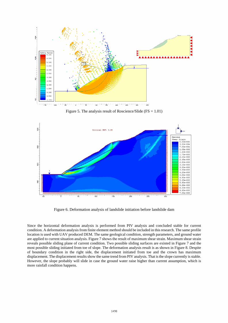
Figure 5. The analysis result of Roscience/Slide (FS = 1.01)
Figure 6. Deformation analysis of landslide initiation before landslide dam
Since the horizontal deformation analysis is performed from PIV analysis and concluded stable for current condition. A deformation analysis from finite element method should be included in this research. The same profile location is used with UAV produced DEM. The same geological condition, strength parameters, and ground water are applied to current situation analysis. Figure 7 shows the result of maximum shear strain. Maximum shear strain reveals possible sliding plane of current condition. Two possible sliding surfaces are existed in Figure 7 and the most possible sliding initiated from toe of slope. The deformation analysis result is as shown in Figure 8. Despite of boundary condition in the right side, the displacement initiated from toe and the crown has maximum displacement. The displacement results show the same trend from PIV analysis. That is the slope currently is stable. However, the slope probably will slide in case the ground water raise higher than current assumption, which is more rainfall condition happens.
1498

Figure 7. Maximum shear strain of current condition
Figure 8. Displacement analysis result of current condition
4. DISCUSSION and CONCLUSION
Multi-rotor drone UAV is used in this study to generate high resolution DSM, DEM and orthophoto with GCPs. The accuracy of DSM has been reduced from more than 8m to less than 10cm. The DEM generated from UAV and previous 5m resolution DEM have some elevation variances with different reference coordinate system. Thus the 5m resolution DEM only adopted for profile fitting in this research to identify landslide surface.
According to field investigation, satellite images, UAV images, the landslide dam was formed from a northwest to southeast sliding mass. Landslide dam stop water passing and resulted in collapse in 2 hours. The turbulent flow induced from dam breaking attacked foundation of road and one lane was collapsed. Back analysis of landslide condition and current stability analysis show that current slope remains stable with the same rainfall event in 2012. However, the slope probably will slide in case the rainfall is higher than 2012.
1499

ACKNOWLEDGMENTS
The author would like to thank the funding from Ministry of Science and Technology, ROC with project No. 104-2625-M-260 -002 and 103-2625-M-260-001. REFERENCES Hsieh, K.-S., Hung, C.-S., Chen, M.-M., Yu, N.-T.(2011),Fossil study of the Chiayang Formation, the middle
member of the Meichi Sandstone and the base of the Lushan Formation in central Taiwan: age constraints on the formations on the eastern flank of the Southern Hsuehshan Range,Special Publication of the Central Geological Survey, No. 25, pp.133-166
Raffel, M., Willert, C., Wereley, S., and Kompenhans, J. (2007). Particle Image Velocimetry - A Practical Guide, Second Ed., Springer
Duncan, J.M., Brandon, T.L., Wright, S.G., Vroman, N.(2008), Stability of I-Walls in New Orleans during Hurricane Katrina, Journal of Geotechnical and Geoenvironmental Engineering, ASCE, pp. 681-691
Azami A., Yacoub T. & Curran J.(2013), Effects of Strength Anisotropy on the Stability of Slopes, GeoManitoba 2012 - Canadian Geotechnical Society Winnepeg, Manitoba, Canada, Sept. 30 - October 3
Allan, F.C., Yacoub, T.E., Curran, J. H. (2012), On Using Spatial Methods for Heterogeneous Slope Stability Analysis, Presentation of Paper - 46th U.S. Rock Mechanics Geomechanics Symposium Chicago, Illinois, USA, June 24-27
Hammah, R.E., Yacoub, T.E., Curran, J.H. (2009), Probabilistic Slope Analysis with the Finite Element Method, Proceedings of the 43rd U.S. Symposium on Rock Mechanics and the 4th U.S.-Canada Rock Mechanics Symposium Asheville, North Carolina, USA, June 2009
Nantou Branch, Soil and Water Conservation Bureau (2006), The Investigation and Treatment of Landslide – 88k to 91k, Tai-14 highway
Lin, M.-L., Wang, K.-L., Liao, J.-T., Lo, W., Wang, T.-T. (2008), Simulation and Monitoring in Areas Susceptible to Landslide Hazard (1/4), MOEACGS
1500