Embed Size (px)
Citation preview

Disclaimer: This website and documents are provided for use by persons outside of the Kansas Department of Transportation as information only. The Kansas Department of Transportation, the State of Kansas, nor its officers or employees, by making this website and documents available for use by persons outside of KDOT, does not undertake any duties or responsibilities of any such person or entity who chooses to use this website and documents. This website and documents should not be substituted for the exercise of a person’s own professional judgment nor the determination by contractors of the appropriate manner and method of construction on projects under their control. It is the user’s obligation to make sure that he/she uses the appropriate practices. Any person using this website and documents agrees that KDOT will not be liable for any commercial loss; inconvenience; loss of use, time, data, goodwill, revenues, profits, or savings; or any other special, incidental, indirect, or consequential damages in any way related to or arising from use of this website and documents.
Chapter 7 - Traffic Design
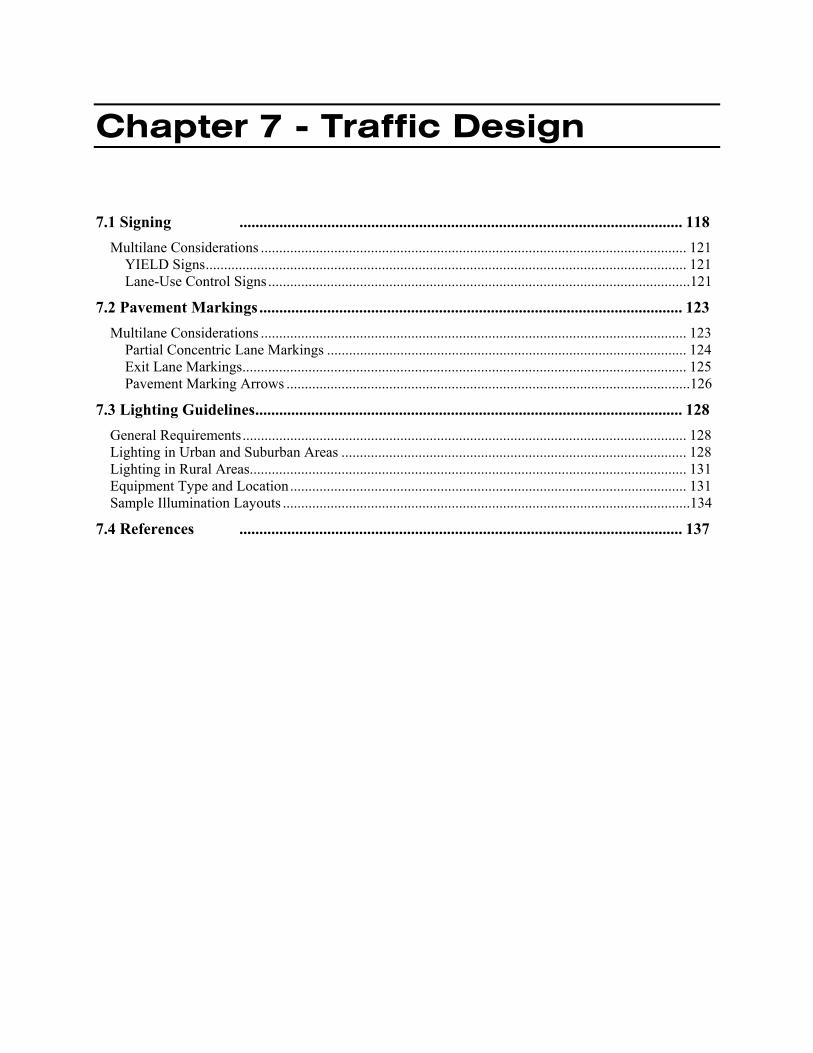
7.1 Signing ............................................................................................................... 118 Multilane Considerations .................................................................................................................... 121
YIELD Signs................................................................................................................................... 121 Lane-Use Control Signs ...................................................................................................................121
7.2 Pavement Markings .......................................................................................................... 123 Multilane Considerations .................................................................................................................... 123
Partial Concentric Lane Markings .................................................................................................. 124 Exit Lane Markings......................................................................................................................... 125 Pavement Marking Arrows ..............................................................................................................126
7.3 Lighting Guidelines........................................................................................................... 128 General Requirements ......................................................................................................................... 128 Lighting in Urban and Suburban Areas .............................................................................................. 128 Lighting in Rural Areas....................................................................................................................... 131 Equipment Type and Location ............................................................................................................ 131 Sample Illumination Layouts ...............................................................................................................134
7.4 References ............................................................................................................... 137

Chapter 7 – Traffic Design Kansas Roundabout Guide Page 118 October 2003
7.1 Signing
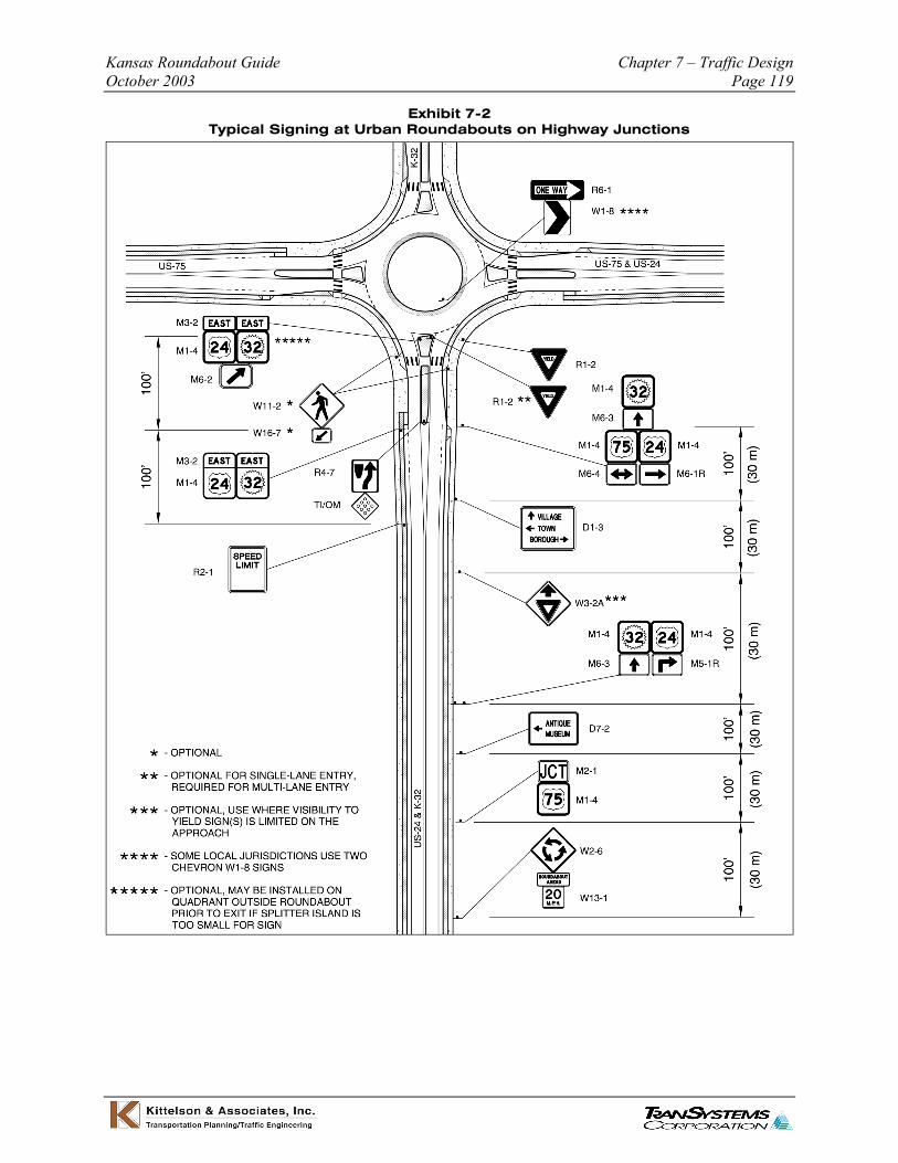
The signing requirements for roundabouts vary slightly depending on the environment and lane configuration. Exhibits 7-1 and 7-2 show signing for typical roundabouts in urban areas at the intersection of local roadways and at highway junctions, respectively. Signing for typical roundabouts in rural environments are displayed in Exhibit 7-3.
Exhibit 7-1 Typical Signing at Urban Roundabouts on Local Roadways
Kansas Roundabout Guide Chapter 7 – Traffic Design October 2003 Page 119
Exhibit 7-2 Typical Signing at Urban Roundabouts on Highway Junctions
Chapter 7 – Traffic Design Kansas Roundabout Guide Page 120 October 2003
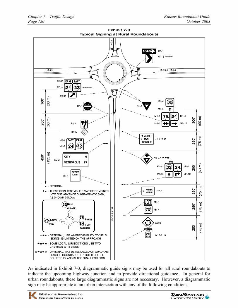
Exhibit 7-3 Typical Signing at Rural Roundabouts
As indicated in Exhibit 7-3, diagrammatic guide signs may be used for all rural roundabouts to indicate the upcoming highway junction and to provide directional guidance. In general for urban roundabouts, these large diagrammatic signs are not necessary. However, a diagrammatic sign may be appropriate at an urban intersection with any of the following conditions:

Kansas Roundabout Guide Chapter 7 – Traffic Design October 2003 Page 121
• The intersection is the junction of two major highway routes,
• The signed highway route makes a bend though the roundabout, or
• The intersection layout or signed route configuration is potentially confusing to unfamiliar drivers.
Multilane Considerations
In general, signing at typical multilane roundabouts is essentially the same as at single-lane roundabouts, as shown in Exhibits 7-1 through 7-3. However, supplemental signs may be needed to enhance clarity and guidance for drivers. The primary differences are related to supplemental YIELD signs and lane-use control signs.
YIELD Signs
For roundabout approaches with more than one lane, YIELD signs should be placed on both the left and right side of the approach. The sign on the left side of the approach is located within the splitter island. YIELD signs should be placed to ensure the faces of the signs are not visible to traffic within the circulatory roadway. If the YIELD sign is visible from the circulatory roadway, it may cause circulating vehicles to yield unnecessarily.
For most intersections, the size of the YIELD signs should be 36” x 36” x 36” (914 mm x 914 mm x 914 mm), in accordance with guidelines from the FHWA Manual on Uniform Traffic Control Devices (MUTCD). Oversized YIELD signs may be considered in special cases based on MUTCD guidance.
Lane-Use Control Signs
For some multilane roundabouts, lane-use control signs may be needed on one or more approaches. Lane-use controls at roundabouts follow the same general principles as those at conventional intersections. For conventional two-lane approaches, at which through movements can be made from either of the two approach lanes, lane-use control signs are not necessary. This is because the rules of the road at intersections require left-turning traffic to use only the left lane, right-turning traffic to use only the right lane, and through traffic to use both lanes unless official traffic control devices indicate otherwise. However, in cases where the turning movement designations for an approach lane may not meet driver expectancy, lane-use control signs should be used.
Lane-use control signs should be used for the following conditions:
• Where only a single exit lane is provided opposite two entry lanes, lane use designations should be made to indicate that an entry lane drops as a turning movement.
• Where left- or right- turning traffic demand dictates the need for more than one left turn lane or more than one right turn lane for capacity reasons.
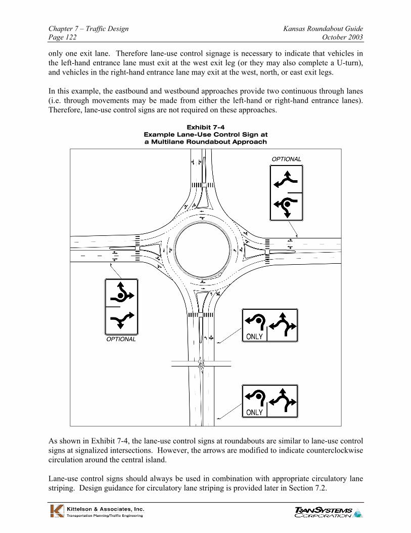
Exhibit 7-4 displays the use of a typical lane-use control sign at a multilane roundabout approach. In the example, the northbound approach consists of two entry lanes, in which left-turns may be made from either lane. The leg directly opposite the northbound entry consists of
Chapter 7 – Traffic Design Kansas Roundabout Guide Page 122 October 2003
only one exit lane. Therefore lane-use control signage is necessary to indicate that vehicles in the left-hand entrance lane must exit at the west exit leg (or they may also complete a U-turn), and vehicles in the right-hand entrance lane may exit at the west, north, or east exit legs.
In this example, the eastbound and westbound approaches provide two continuous through lanes (i.e. through movements may be made from either the left-hand or right-hand entrance lanes). Therefore, lane-use control signs are not required on these approaches.
Exhibit 7-4 Example Lane-Use Control Sign at a Multilane Roundabout Approach
As shown in Exhibit 7-4, the lane-use control signs at roundabouts are similar to lane-use control signs at signalized intersections. However, the arrows are modified to indicate counterclockwise circulation around the central island.
Lane-use control signs should always be used in combination with appropriate circulatory lane striping. Design guidance for circulatory lane striping is provided later in Section 7.2.

Kansas Roundabout Guide Chapter 7 – Traffic Design October 2003 Page 123
7.2 Pavement Markings
Striping and pavement marking specifications for a typical roundabout approach are shown in Exhibit 7-5.
Exhibit 7-5 Pavement Markings at a Typical Roundabout Approach
Note: Standards for cities and other local jurisdictions may vary from KDOT standards.
Multilane Considerations
In general at multilane roundabouts, lane lines should not be striped within the circulatory roadway. This generally promotes more even use of the entry lanes, and it causes entering and circulating drivers to be cognizant of other vehicles in the roundabout. It also encourages large semi-trailers and oversized vehicles to use the entire width of the circulatory, which may reduce the overall width required for the circulatory roadway and truck apron. In some cases, however, providing circulatory lane markings can enhance the capacity or safety of a multilane roundabout.
When circulatory lane markings are considered at a multilane roundabout, two options for the design of these markings are available. These two options are:

Chapter 7 – Traffic Design Kansas Roundabout Guide Page 124 October 2003
• Partial concentric lane markings, and
• Exit lane markings.
The applications and design details for each of these striping schemes are discussed in the next sections.
Partial Concentric Lane Markings
Partial concentric lane markings consist of a solid white stripe placed at a uniform offset from the central island. The stripe is broken between each entry and the adjacent upstream exit to enable entering and exiting movements. Thus, the lane markings are provided only in front of the splitter islands. Exhibit 7-6 displays an example of partial concentric circulatory lane markings.
Exhibit 7-6 Partial Concentric Circulatory Lane Markings
Partial concentric circulatory lane markings can assist drivers in entering into the appropriate circulatory lanes. These markings should be considered at existing roundabouts with a known problem of entering vehicles cutting across the circulatory roadway. In particular, they can be beneficial at roundabouts where vehicles in the right-hand entry lane commonly enter into the inside of the circulatory roadway, cutting in front of vehicles in the left-hand entry lane.
Kansas Roundabout Guide Chapter 7 – Traffic Design October 2003 Page 125
Exit Lane Markings
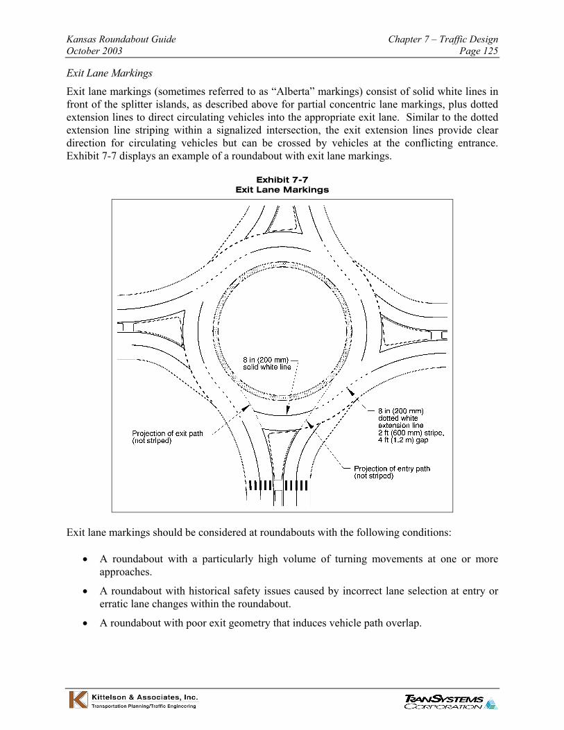
Exit lane markings (sometimes referred to as “Alberta” markings) consist of solid white lines in front of the splitter islands, as described above for partial concentric lane markings, plus dotted extension lines to direct circulating vehicles into the appropriate exit lane. Similar to the dotted extension line striping within a signalized intersection, the exit extension lines provide clear direction for circulating vehicles but can be crossed by vehicles at the conflicting entrance. Exhibit 7-7 displays an example of a roundabout with exit lane markings.
Exhibit 7-7 Exit Lane Markings
Exit lane markings should be considered at roundabouts with the following conditions:
• A roundabout with a particularly high volume of turning movements at one or more approaches.
• A roundabout with historical safety issues caused by incorrect lane selection at entry or erratic lane changes within the roundabout.
• A roundabout with poor exit geometry that induces vehicle path overlap.

Chapter 7 – Traffic Design Kansas Roundabout Guide Page 126 October 2003
Pavement Marking Arrows
For single-lane roundabouts and conventional double-lane roundabouts, pavement marking arrows are not required. For multilane roundabouts that require lane-use designations (see Section 7.1), pavement marking arrows may be used to denote the designated turning movements of each lane on the approaches and circulatory roadway. Exhibit 7-8 displays a typical use of pavement marking arrows at a double-lane roundabout.
Exhibit 7-8 Pavement Marking Arrows
As shown in Exhibit 7-8, pavement marking arrows are placed on the approach roadway in advance of the roundabout and again immediately behind the entry line (similar to signalized or stop-controlled intersections). Pavement marking arrows may also be used on the circulatory
Kansas Roundabout Guide Chapter 7 – Traffic Design October 2003 Page 127
roadway to clarify the designated movements of each circulatory lane. Within the circulatory roadway, a left-turn arrow is used to denote the driver must continue circulating to the left, and a through arrow is used to indicate that the driver must exit at the next exit. A shared left-through arrow is used to indicate the driver may either continue circulating or exit at the next exit.
The use of left-turn arrows for pavement markings is a critically important aspect of properly marking multilane roundabouts. A common concern is that the left turn arrow will induce drivers to turn left into oncoming circulatory traffic. However, a properly designed roundabout has several design elements that make this movement unlikely: (1) an acute turning angle of 120 to 150 degrees; (2) a one-way sign in the central island; (3) a chevron plate in the central island; and (4) pavement arrows on the circulatory roadway. In addition, the presence of circulating vehicles provides a fifth cue of the proper direction of circulation. In the rare event that a vehicle turns left in front of the central island, it almost always happens during times of very low traffic volumes and at low speeds where the consequence of failure is little more than embarrassment to the driver. On the other hand, the failure to include left-turning pavement arrows may result in driver confusion during times of moderate to heavy traffic and more frequent circulating-exit conflicts due to improper lane use (Ref. 4).
In the example design shown in Exhibit 7-8, note that a triangular-shaped hatch pattern is used on the left side of the circulatory roadway opposite the south splitter island to shift the circulatory lanes slightly to the outside. This striping is necessary to guide eastbound left-turn vehicles into the outer circulatory lane (in effect, spiraling them out). Otherwise, they end up being trapped as a U-turn.

Chapter 7 – Traffic Design Kansas Roundabout Guide Page 128 October 2003
7.3 Lighting Guidelines
This section presents recommended guidelines for lighting of roundabouts on facilities within Kansas. The information in this section is based on the following sources:
• FHWA, Roundabouts: An Informational Guide, 2000.
• ANSI / IESNA RP-8-00, American National Standard Practice for Roadway Lighting, 2000. (Note: The illumination guidance in this document is more current and supercedes the information in FHWA’s Roundabouts: An Informational Guide.)
• AS/NZS 1158.1.3:1997, Road lighting, Australian/New Zealand Standard, 1997.
• Centre d’Etudes sur les Réseaux les Transports, l’Urbanisme et les constructions publiques (CERTU), L’Éclairage des Carrefours à Sens Giratoire (The Illumination of Roundabout Intersections), Lyon, France: CERTU, 1991.
General Requirements
Lighting should be provided at all roundabouts, whether in rural or urban settings. The specific lighting requirements for each setting are discussed below. Lighting is required for roundabouts on the Kansas state highway system.
Lighting should be installed and operational before the roundabout is open to traffic. If a portion of the roundabout will be opened to accommodate traffic on a temporary basis, lighting should be provided. If permanent lighting cannot be installed to meet construction schedules, temporary lighting will be allowed, with the approval of the engineer.
Refer to the KDOT Utility Accommodation Policy for requirements pertaining to the placement of lighting facilities within the public right-of-way. This policy applies to the location, construction, maintenance, removal and relocation of all private, public and cooperatively owned utilities within the highway rights-of-way under the jurisdiction of the Secretary of the Kansas Department of Transportation (KDOT).
Lighting in Urban and Suburban Areas
The recommended practice for determining proper roadway illumination is provided in ANSI/IESNA RP-8-00, published by the Illuminating Engineering Society of North America. The discussion in this section focuses on the illuminance method, which is commonly used for illumination design at roundabouts. RP-8-00 discusses other methods such as luminance and small target visibility; the reader is encouraged to refer to that document for discussion of those methods, as well as discussion on the proper method to calculate the critical values for each criteria.
The basic principle behind the lighting of roundabouts in urban and suburban areas is that the amount of light on the intersection should be proportional to the classification of the intersecting streets and equal to the sum of the values used for each separate street. In other words, if Street A is illuminated at a level of x and Street B is illuminated at a level of y, the intersection should
Kansas Roundabout Guide Chapter 7 – Traffic Design October 2003 Page 129
be illuminated at a level of x + y. In addition, RP-8-00 specifies that if an intersecting roadway is illuminated above the recommended value, then the intersection illuminance value should be proportionately increased. Therefore, the illumination design for a roundabout in an urban or suburban area should be designed to properly illuminate the roundabout while being compatible with the illumination levels on approaching roadways.
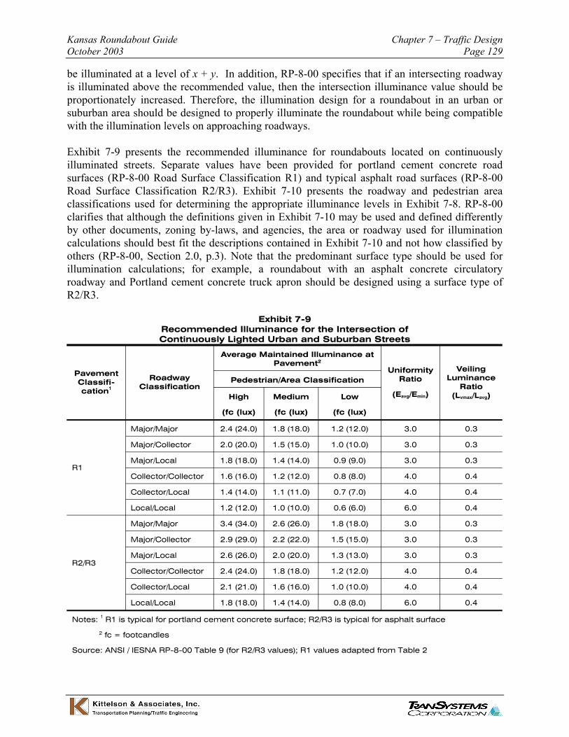
Exhibit 7-9 presents the recommended illuminance for roundabouts located on continuously illuminated streets. Separate values have been provided for portland cement concrete road surfaces (RP-8-00 Road Surface Classification R1) and typical asphalt road surfaces (RP-8-00 Road Surface Classification R2/R3). Exhibit 7-10 presents the roadway and pedestrian area classifications used for determining the appropriate illuminance levels in Exhibit 7-8. RP-8-00 clarifies that although the definitions given in Exhibit 7-10 may be used and defined differently by other documents, zoning by-laws, and agencies, the area or roadway used for illumination calculations should best fit the descriptions contained in Exhibit 7-10 and not how classified by others (RP-8-00, Section 2.0, p.3). Note that the predominant surface type should be used for illumination calculations; for example, a roundabout with an asphalt concrete circulatory roadway and Portland cement concrete truck apron should be designed using a surface type of R2/R3.
Exhibit 7-9 Recommended Illuminance for the Intersection of Continuously Lighted Urban and Suburban Streets
Average Maintained Illuminance at Pavement2
Pavement Classification1
Roadway Classification
Uniformity Ratio
(Eavg/Emin)
Veiling Luminance
Ratio (Lvmax/Lavg)
Pedestrian/Area Classification
High
(fc (lux)
Medium
(fc (lux)
Low
(fc (lux)
Major/Major 2.4 (24.0) 1.8 (18.0) 1.2 (12.0) 3.0 0.3
Major/Collector 2.0 (20.0) 1.5 (15.0) 1.0 (10.0) 3.0 0.3
R1 Major/Local 1.8 (18.0) 1.4 (14.0) 0.9 (9.0) 3.0 0.3
Collector/Collector 1.6 (16.0) 1.2 (12.0) 0.8 (8.0) 4.0 0.4
Collector/Local 1.4 (14.0) 1.1 (11.0) 0.7 (7.0) 4.0 0.4
Local/Local 1.2 (12.0) 1.0 (10.0) 0.6 (6.0) 6.0 0.4
Major/Major 3.4 (34.0) 2.6 (26.0) 1.8 (18.0) 3.0 0.3
Major/Collector 2.9 (29.0) 2.2 (22.0) 1.5 (15.0) 3.0 0.3
R2/R3 Major/Local 2.6 (26.0) 2.0 (20.0) 1.3 (13.0) 3.0 0.3
Collector/Collector 2.4 (24.0) 1.8 (18.0) 1.2 (12.0) 4.0 0.4
Collector/Local 2.1 (21.0) 1.6 (16.0) 1.0 (10.0) 4.0 0.4
Local/Local 1.8 (18.0) 1.4 (14.0) 0.8 (8.0) 6.0 0.4
Notes: 1 R1 is typical for portland cement concrete surface; R2/R3 is typical for asphalt surface
2 fc = footcandles
Source: ANSI / IESNA RP-8-00 Table 9 (for R2/R3 values); R1 values adapted from Table 2
Chapter 7 – Traffic Design Kansas Roundabout Guide Page 130 October 2003
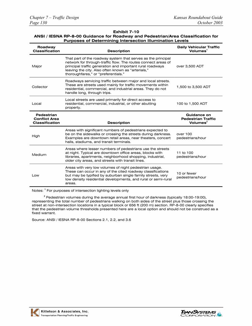
Exhibit 7-10 ANSI / IESNA RP-8-00 Guidance for Roadway and Pedestrian/Area Classification for
Purposes of Determining Intersection Illumination Levels
Roadway Classification Description
Daily Vehicular Traffic Volumes1
That part of the roadway system that serves as the principal network for through-traffic flow. The routes connect areas of
Major principal traffic generation and important rural roadways over 3,500 ADT leaving the city. Also often known as “arterials,” thoroughfares,” or “preferentials.”
Roadways servicing traffic between major and local streets.
Collector These are streets used mainly for traffic movements within residential, commercial, and industrial areas. They do not 1,500 to 3,500 ADT
handle long, through trips.
Local streets are used primarily for direct access to Local residential, commercial, industrial, or other abutting 100 to 1,500 ADT
property.
Pedestrian Guidance on Conflict Area Pedestrian Traffic Classification Description Volumes2
Areas with significant numbers of pedestrians expected to
High be on the sidewalks or crossing the streets during darkness. Examples are downtown retail areas, near theaters, concert
over 100 pedestrians/hour
halls, stadiums, and transit terminals.
Areas where lesser numbers of pedestrians use the streets
Medium at night. Typical are downtown office areas, blocks with libraries, apartments, neighborhood shopping, industrial,
11 to 100 pedestrians/hour
older city areas, and streets with transit lines.
Areas with very low volumes of night pedestrian usage.
Low These can occur in any of the cited roadway classifications but may be typified by suburban single family streets, very low density residential developments, and rural or semi-rural
10 or fewer pedestrians/hour
areas.
Notes: 1 For purposes of intersection lighting levels only
2 Pedestrian volumes during the average annual first hour of darkness (typically 18:00-19:00), representing the total number of pedestrians walking on both sides of the street plus those crossing the street at non-intersection locations in a typical block or 656 ft (200 m) section. RP-8-00 clearly specifies that the pedestrian volume thresholds presented here are a local option and should not be construed as a fixed warrant.
Source: ANSI / IESNA RP-8-00 Sections 2.1, 2.2, and 3.6
Kansas Roundabout Guide Chapter 7 – Traffic Design October 2003 Page 131
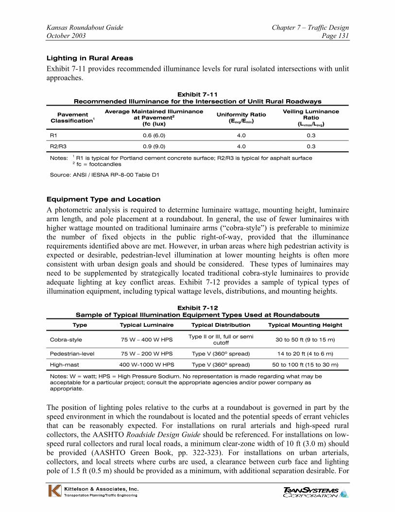
Lighting in Rural Areas
Exhibit 7-11 provides recommended illuminance levels for rural isolated intersections with unlit approaches.
Exhibit 7-11 Recommended Illuminance for the Intersection of Unlit Rural Roadways
Pavement Classification1
Average Maintained Illuminance at Pavement2
(fc (lux)
Uniformity Ratio (Eavg/Emin)
Veiling Luminance Ratio
(Lvmax/Lavg)
R1 0.6 (6.0) 4.0 0.3
R2/R3 0.9 (9.0) 4.0 0.3
Notes: 1 R1 is typical for Portland cement concrete surface; R2/R3 is typical for asphalt surface 2 fc = footcandles
Source: ANSI / IESNA RP-8-00 Table D1
Equipment Type and Location
A photometric analysis is required to determine luminaire wattage, mounting height, luminaire arm length, and pole placement at a roundabout. In general, the use of fewer luminaires with higher wattage mounted on traditional luminaire arms (“cobra-style”) is preferable to minimize the number of fixed objects in the public right-of-way, provided that the illuminance requirements identified above are met. However, in urban areas where high pedestrian activity is expected or desirable, pedestrian-level illumination at lower mounting heights is often more consistent with urban design goals and should be considered. These types of luminaires may need to be supplemented by strategically located traditional cobra-style luminaires to provide adequate lighting at key conflict areas. Exhibit 7-12 provides a sample of typical types of illumination equipment, including typical wattage levels, distributions, and mounting heights.
Exhibit 7-12 Sample of Typical Illumination Equipment Types Used at Roundabouts
Type Typical Luminaire Typical Distribution Typical Mounting Height
Cobra-style 75 W – 400 W HPS Type II or III, full or semi cutoff 30 to 50 ft (9 to 15 m)
Pedestrian-level 75 W – 200 W HPS Type V (360º spread) 14 to 20 ft (4 to 6 m)
High-mast 400 W-1000 W HPS Type V (360º spread) 50 to 100 ft (15 to 30 m)
Notes: W = watt; HPS = High Pressure Sodium. No representation is made regarding what may be acceptable for a particular project; consult the appropriate agencies and/or power company as appropriate.
The position of lighting poles relative to the curbs at a roundabout is governed in part by the speed environment in which the roundabout is located and the potential speeds of errant vehicles that can be reasonably expected. For installations on rural arterials and high-speed rural collectors, the AASHTO Roadside Design Guide should be referenced. For installations on low-speed rural collectors and rural local roads, a minimum clear-zone width of 10 ft (3.0 m) should be provided (AASHTO Green Book, pp. 322-323). For installations on urban arterials, collectors, and local streets where curbs are used, a clearance between curb face and lighting pole of 1.5 ft (0.5 m) should be provided as a minimum, with additional separation desirable. For

Chapter 7 – Traffic Design Kansas Roundabout Guide Page 132 October 2003
areas within or on the approach to a roundabout where the overhang of a turning truck could strike a lighting pole, a minimum offset distance of 3 ft (1.0 m) should be provided (AASHTO Green Book, pp. 485-486).
Exhibit 7-13 suggests critical conflict areas where run-off-the-road crashes are most prevalent at roundabouts. In these areas, lighting poles should be placed as far back from the curb face as practical. In rural areas where pedestrian activity is low, breakaway pole bases are required for poles located in these critical areas.
Exhibit 7-13 Critical Conflict Areas Affecting Lighting Pole Placement
Source: Adapted from AS/NZS 1158.1.3:1997, Road lighting, Australian/New Zealand Standard, 1997, Figure 8.2, p. 39.
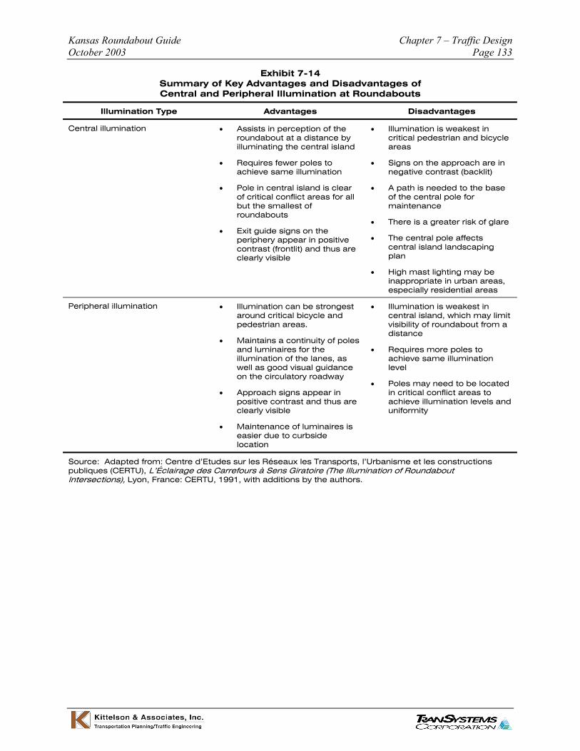
Roundabouts can be illuminated from a set of luminaires in the middle of the central island, from luminaires arrayed around the periphery of the roundabout, or by a combination of the two. Exhibit 7-14 provides a summary of the key advantages and disadvantages of central and peripheral illumination. In general, illumination from the periphery of the roundabout is recommended due to a greater ability to provide maximum illumination at key conflict areas.
Kansas Roundabout Guide Chapter 7 – Traffic Design October 2003 Page 133
Exhibit 7-14 Summary of Key Advantages and Disadvantages of Central and Peripheral Illumination at Roundabouts
Illumination Type Advantages Disadvantages
Central illumination • Assists in perception of the • Illumination is weakest in roundabout at a distance by critical pedestrian and bicycle illuminating the central island areas
• Requires fewer poles to • Signs on the approach are in achieve same illumination negative contrast (backlit)
• Pole in central island is clear • A path is needed to the base of critical conflict areas for all of the central pole for but the smallest of maintenance roundabouts
• There is a greater risk of glare • Exit guide signs on the
periphery appear in positive contrast (frontlit) and thus are clearly visible
• The central pole affects central island landscaping plan
• High mast lighting may be inappropriate in urban areas, especially residential areas
Peripheral illumination • Illumination can be strongest • Illumination is weakest in around critical bicycle and central island, which may limit pedestrian areas. visibility of roundabout from a
distance • Maintains a continuity of poles
and luminaires for the • Requires more poles to illumination of the lanes, as achieve same illumination well as good visual guidance level on the circulatory roadway
• Poles may need to be located • Approach signs appear in
positive contrast and thus are clearly visible
in critical conflict areas to achieve illumination levels and uniformity
• Maintenance of luminaires is easier due to curbside location
Source: Adapted from: Centre d’Etudes sur les Réseaux les Transports, l’Urbanisme et les constructions publiques (CERTU), L’Éclairage des Carrefours à Sens Giratoire (The Illumination of Roundabout Intersections), Lyon, France: CERTU, 1991, with additions by the authors.

Chapter 7 – Traffic Design Kansas Roundabout Guide Page 134 October 2003
Sample Illumination Layouts
The following three exhibits present some sample illumination plans demonstrating layouts using various types of luminaires. Each illumination plan has been customized to the specific geometry of the roundabout, photometric requirements, equipment options, and site constraints. Therefore, the reader is urged to exercise considerable caution if attempting to adapt one or more of these plans to another location.
Exhibit 7-15 Example of Illumination Using Cobra-Style Luminaires
Inscribed Circle 190 ft (58 m) Diameter:
Equipment: Luminaires over circulatory roadway: 400 W HPS, Type M-C-III, 37 ft (11.2 m) mounting height Remainder: 200 W HPS, Type M-C-III, 35 ft (10.7 m) mounting height
Photometric Avg. illuminance: 2.6 fc (26 lux) Requirements: Avg./min. uniformity: 3:1
Layout:

Kansas Roundabout Guide Chapter 7 – Traffic Design October 2003 Page 135
Exhibit 7-16 Example of Illumination Using Pedestrian-Level Luminaires
Inscribed Circle Diameter:
120 ft (37 m)
Equipment: Pedestrian-level luminaires: 250 W HPS, Type V, 18 ft (5.5 m) mounting height
Photometric Avg. illuminance: 2.7 fc (27 lux) Requirements: Avg./min. uniformity: 3:1
Layout:
Chapter 7 – Traffic Design Kansas Roundabout Guide Page 136 October 2003
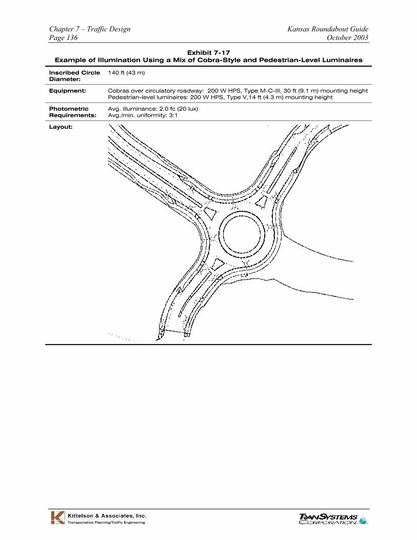
Exhibit 7-17 Example of Illumination Using a Mix of Cobra-Style and Pedestrian-Level Luminaires
Inscribed Circle 140 ft (43 m) Diameter:
Equipment: Cobras over circulatory roadway: 200 W HPS, Type M-C-III, 30 ft (9.1 m) mounting height Pedestrian-level luminaires: 200 W HPS, Type V,14 ft (4.3 m) mounting height
Photometric Avg. illuminance: 2.0 fc (20 lux) Requirements: Avg./min. uniformity: 3:1
Layout:

Kansas Roundabout Guide Chapter 7 – Traffic Design October 2003 Page 137
7.4 References
1. MUTCD Millennium Edition – Proposed Revision No. 2, May 21 2001.
2. The Highways Agency (United Kingdom). Design of Road Markings at Roundabouts. TA 78/97
3. Queensland Department of Main Roads. Traffic Engineering Manual – Pavement Marking Technical Guideline, Section 4.6 Pavement Marking of Multilane Roundabouts. March 1998
4. Adapted from material presented by Barry Crown at meeting of Roundabout Task Force, Markings Technical Committee, National Committee on Uniform Traffic Control Devices, Savannah, GA, June 2003


![Exhibit M: TAS Website Excerpts, January 24, 2014 · Enter your e-mail: ._____ _____,, [~] DISCLAIMER: The information provided on this website is intended for educational purposes](https://img.pdfslide.us/doc/110x75/60a19c5e46786e259c0156dd/exhibit-m-tas-website-excerpts-january-24-2014-enter-your-e-mail-.jpg)