Embed Size (px)
Citation preview
Purdue UniversityPurdue e-Pubs
International Compressor Engineering Conference School of Mechanical Engineering
1992
Discharge Gas Temperature Control inReciprocating Hermetic Compressors Modified forR134a/R22 Refrigerants Operation as Substitutesof Present R12/R502F. PeruzziAspera Division of Whirlpool Italia Srl; Italy
G. LampugnaniAspera Division of Whirlpool Italia Srl; Italy
Follow this and additional works at: https://docs.lib.purdue.edu/icec
This document has been made available through Purdue e-Pubs, a service of the Purdue University Libraries. Please contact [email protected] foradditional information.Complete proceedings may be acquired in print and on CD-ROM directly from the Ray W. Herrick Laboratories at https://engineering.purdue.edu/Herrick/Events/orderlit.html
Peruzzi, F. and Lampugnani, G., "Discharge Gas Temperature Control in Reciprocating Hermetic Compressors Modified for R134a/R22 Refrigerants Operation as Substitutes of Present R12/R502" (1992). International Compressor Engineering Conference. Paper 874.https://docs.lib.purdue.edu/icec/874
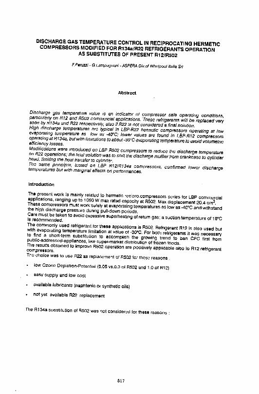
DISCHARGE GAS TEMPERATURE CONTROL IN RECIPROCATING HERMETIC COMPRESSORS MODIFIED FOR R134a/R22 REFRIGERANTS OPERATION AS SUBSTITUTES OF PRESENT R12/R502
F. Peruzzi- G.Lampugnani- ASPERA D/v.of Whirlpoolltalia Sri
Abstract
Discharge gas temperature value is an indicator of compressor safe operating conditions, particularly on R12 and R502 commercial applications. These refrigerants will be replaced very soon by R134a and R22 respectively, also if R22 is not considered a final solution. High discharge temperatures are typical in LBP-R22 hermetic compressors operating at low evaporating temperature as low as -40"C; lower values are found in LBP-R12 compressors operating at R134a, but with limitations to about -30°C evaporating temperature to avoid volumetflc efficiency losses. Modifications were mtroduced on LBP R502 compressors to reduce the discharge temperature on R22 operations; the final solution was to shift the discharge muffler from crankcase to cylinder head, limiting the heat transfer to cylmder. The same prmciple, tested on LBP R12/R134a compressors, confirmed lower discharge temperatures bur with margmal effects on performances.
Introduction
The present work is mainly related to hermetic recipro.compressors series tor l9P commercial applications, ranging up to 1050 W max rated capacity at R502. Max displacement 20.4 cm3. These compressors must work safely at evaporating temperatures as low as -40"C and withstand the high discharge pressure during pull-down periods. Care must be taken to avoid excessive superheating of return gas; a suction temperature of 1 B"C is recommended. The commonly used refrigerant for these applications is R502. Refrigerant R12 is also used but with evaporating temperature limitation at value of -30°C. For both refrigerants it was necessary to find a shon-term substitution to accomplish the growing trend to ban CFC first from public-addressed-appliances, like s"per-market distribution of frozen foods. The results obtained to improve R502 operation are poSitively applicable also to R12 refrigerant compressors. The choice was to use A22 as replacement of R502 for these reasons .
low Ozone-Depletoon-Potentiai (0.05 vs.0.3 of R502 and 1.0 of R12)
easy supply and low cost
available l"bricants (naphtenic or synthetic oils)
not yet available R22 replacement
The R134a substitution o1 R502 was not considered for these reasons :
817
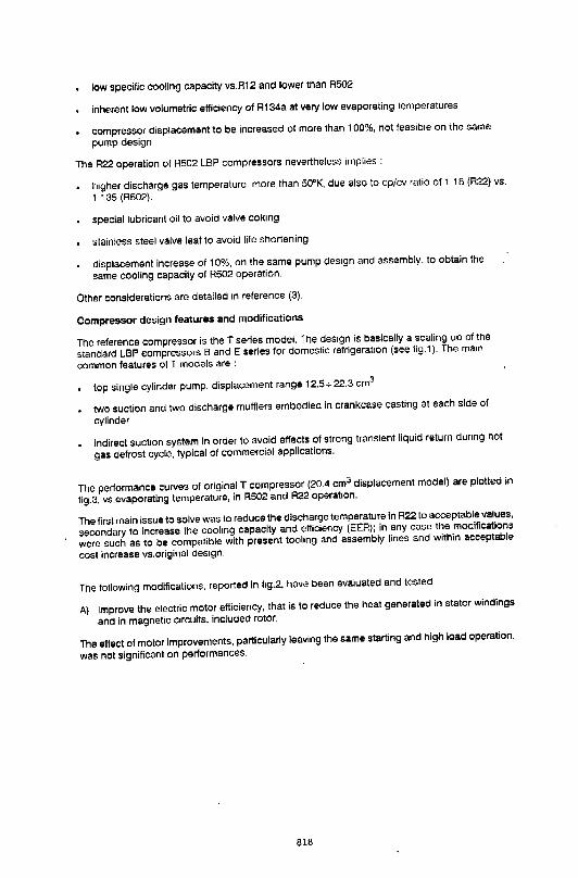
low specific cooling capacity vs.R12 and lower than R502
inherent low volumetric efficiency of R134a at very low evaporating temperatures
compressor displacement to be increased of more than 1 00%, not feasible on the same
pump design.
The R22 operation of R502 LBP compressors nevertheless implies :
higher discharge gas temperature, more than 50"K, due also to cp/cv ratio of 1 18 (R22) vs.
1 135 (R502).
special lubricant oil to avoid valve coking
stainless steel valve leaf to avoid life shortening
displacement increase of 10%, on the same pump design and assembly, to obtain the
same cooling capacity of R502 operation.
Other considerations are detailed 1n reference (3).
Compressor design features and modifications
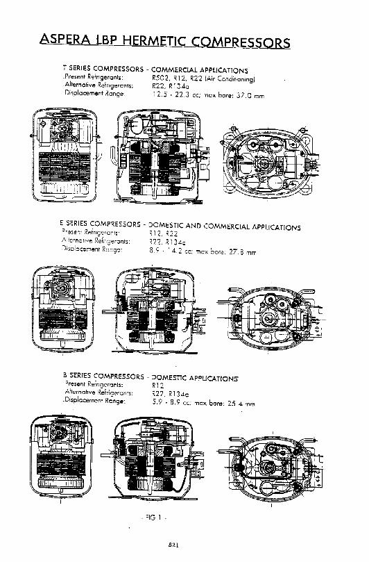
The reference compressor is the T series model. The des1gn is basically a scaling up of the
standard LBP compressors Band E series for domestic refrigeration (see fig.1). The ma1n
common features of T models are :
top single cylinder pump, displacement range 12.5+22.3 cm3
two suction and two discharge mufflers embodied in crankcase casting at each side of
cylinder
indirect suction system in order to avoid effects of strong transient liquid return dunng hot
gas defrost cycle, typical of commercial applications.
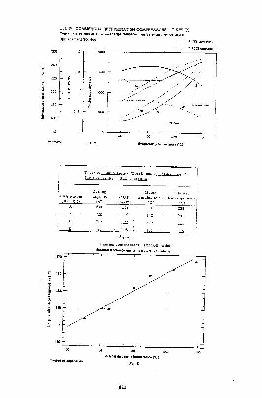
The performance curves of original T compressor (20.4 cm3 displacement model) are plotted in
fig.3, vs.evaporating temperature, in R502 and A22 operation.
The first main issue to solve was to reduce the discharge temperature in A22 to acceptable values,
secondary to increase the cooling capacity and efficiency (EER); in any case the modifications
were such as to be compatible with present tooling and assembly lines and within acceptable
cost increase vs.original des1gn.
The following modifications. reported in f1g.2, have been evaluated and tested
A) Improve the electric motor efficiency, that is to reduce the heat generated in stator windings
and in magnetic Circuits, included rotor.
The effect of motor improvements, particularly leaving the same starting and high load operation,
was not significant on performances.
618
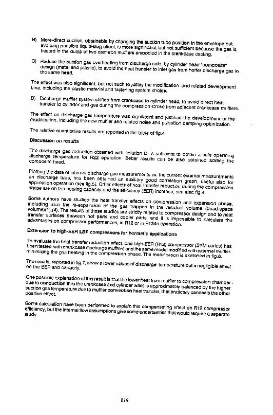
8) More.Qirect suction, obtainable by changing the suction tube position in the envelope but avoiding possible liquid-slug effect, is more significant, but not sufficient because the gas is heated in the ducts of two cast-rron mufflers embodied in the crankcase casting. C) Reduce the suction gas overheating from discharge s1de, by cylinder head "composite" design (metal and plastic), to avoid the heat transfer to inlet gas from hotter discharge gas in the same head.
The effect was also significant, but not such to 1ustity the modification and related development time, including the plastic material and fastening system choice.
D) Discharge muffler system shifted from crankcase to cylinder head, to avoid direct heat transfer to cylinder and gas during the compression stroke from adjacent crankcase mufflers_ The effect on discharge gas temperature was significant and justified the development of the modification, including the new muffler and related noise and pulsation damping optimization. The relative quantitative results are reported In the table of fig.4. Discussion on results
The discharge gas reduction obta1ned with solution D, is suffiCient to obtain a safe operating discharge temperature for R22 operation Better results can be also obtained adding the composite head.
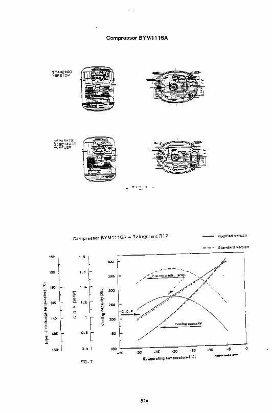
Plotting the data of Internal discharge gas measurements vs. the current external measurements on discharge tube, has been obtained an auxil1ary good correlation graph, useful also for application operation (see fig.5). Other effects of heat transfer reduction during the compression phase are on the cooling capac1ty and the efficiency (EE':ll increase, see also fig.4. Some authors have studied the heat transfer effects on compression and expans1on phase, Including also the re-expansion of the gas trapped in the res1dual volume (dead-space volume)(1 ),(4). The results of these studies are strictly related to compressor design and to heat transfer surfaces between hot parts and cooler parts, and it is impossible to calculate the advantages on compressor performances, in R12 or in R134a operation. Extension to high-EER LBP compressors for hermetic applications To evaluate the heat transfer reduction effect_, one high-EER (R12) compressor (BYM series) has been tested with crankcase discharge mufflers and the same model modified with external muffler, minimizing the gas heat•ng in the compression phase. The modification is sketched in fig.6. The results, reported in fig.7, show a lower values of discharge temperature but a negligible effect on the EER and capacity.
One possible explanation of this result is that the lower heat from muffler to compression chamber . due to conduction thru the crankcase and cylinder walls IS approximately balanced by the higher suction gas temperature due to muffler convection heat transfer, that pratically canceals the other positive effect.
Some calculation have been performed to explain this compensating effect on R12 compressor efficiency, but the internal flow assumptions give some uncertainties that would require a separate study.
819
In any case. the effect of reduced discharge temperature is positive on application for lower
condenser load and to reduce the risk of coking at high climate temperature.
Extension to new compressor design
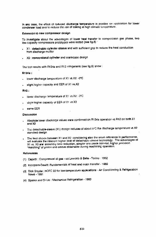
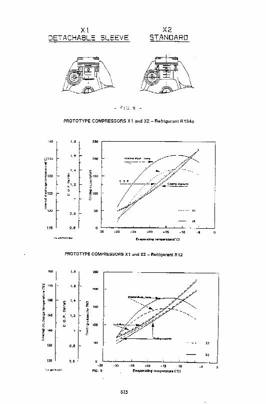
To investigate about the advantages of lower heat transfer to compression gas phase, two
low-capacity compressors prototypes were tested (see fig.8) ·
X1 : detachable cylinder sleeve and with sufficient gap to reduce the heat conduction
from discharge muffler
X2 : conventional cylinder and crankcase design
The test results with R134a and R12 refrigerants (see fig.9) show :
R134a:
lower discharge temperature of X1 vs.X2: -s•c
slight higher capacity and EER of XI vs.X2
R12;
lower discharge temperature of XI vs.X2: -SOC
slight higher capac1ty of EER of XI vs_X2
same EER
Discussion
Absolute lower discharge values were confirmed on R134a operation vs.RI2 on both X1
andX2
The detachable-sleeve {XI) design reduces of about s•c the discharge temperature vs.X2
standard design
The final choice between Xt and X2, considering also the small difference in performance,
will evaluate the inherent higher cost of detachable sleeve technology . The advantages of
XI vs. X2 are: assembly time reduction, simpler one-piece con-rod, higher precision
"matching" of piston and sleeve obtainable during machining operation.
References
(I) Capetti: Compressori di gas- ed.Levrotto & Bella- Torino- 1952
(2) lncropera-Dewitt: Fundamentals of heat and mass transfer - 1989
(3) Dick Snyder: HCFC 22 for low-temperature applications - AiT Conditioning & Refrigeration
News -1991
{4) Sparks and Oi Lio: Mechanical Refrigeration -1959
820
ASPERA LBP HERMETtc_c_oMPRESSORS
T SERIES COMPRESSORS • COMMERCIAL APPLICATIONS .Present Refngerants: R502, R 12, R22 (Air Conditraningi .Alternative Refrtgerants; R22. R 13.da .Displacement Range: 12.5 - 22.3 cc; max bore: 37.0 mm
E S~RIES COMPRESSORS - DOMESTIC AND COMMERCIAL APPLICATIONS ?rese~t Refrtceronrs· R 12, -~22 Alternatrve R~fnaeronts: R22, R I ].do Disolocement R~nge: 8. 9 - I .d. 2 cc; "1"\0X bore: 27.8 mm
B SERIES COMPRESSORS- DOMESTIC APPLICATIONS Present Refrtoeronts: R l 2 Alternative R~frigeranr>: R22, R l3.do
.Displacement Range: 5.9 - 8.9 cr:; max bore: 25.4. mm
- "IG 1 -
821
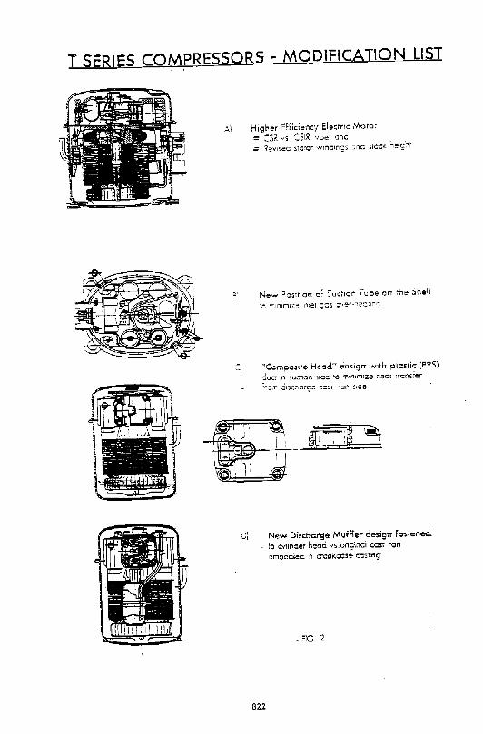
T SERIES COMPRESSORS ~ MODIFICATION LIST
A) Higher Efficiency Electr1c Motor
= ::sK "5 CSlR -voe, ond
= ~~v1s~c :m::uor w!no1n~.s .::::nd ~iccx. 'ietglir
31 New Position of Suct1on I ube on the Shell
:i ",CompoSite Heod" desigrT w1tf-r plastic [PPS)
::ucr 1n 5.uC':'Ion 51ce to m.tntMIZe: nec:r i'icnsrl!!!!:r
.,.om :.::ltsc:'lc.rs~ .:.:sr ran .s1de
D) New Discharge- MufHer desigrt Fastened
to cYiincer heod. vs_orlginoi c.c:-sr 1rQn
emoocie:c. 1r'1 c:-anr:.cose- co.s.nng
622
E . i . 0>
"' -s • !
260
240
220
~00
180
160
HO
I.. B . P. COMMERCIAL REFRIGERA TlON COMPRESSORS - T SERIES P'trfcrmancu anclln\trna.l d.l.scl'large temp•rabH~~ts Vs •vap. temp•ratu,-• Dlsplac•m•ot 20 .4cc T R22 open.t.on
T F!:-502. oper~t1on 2000
1.5
i ~ ~
0. ,, 0 0. . u
" <
~ u
nlon!M,IW FIQ. 3
'i MothHQtiOnj
(Se.: rt~_;:,)
-~
c I)
T ;,t:r!es cum~.:..__L!ll!.::!£ rtrut!t•! l~ll.L.,l !J,I.lle u( res~r.!JtS R,-~~~
Cv~o:~lili~ ~11,\t.r.i(." lut.t.!:I."II..Li i I
t.:.:.t.pacu:y C.(.).!' wuuJ.in~ teuqJ. 1 Ji.:!.Chll.r,e [C:UII)-11 IWI [W/W] ("C] oJO l.lS !10
723 I l9 ! 12
7!0 l..!J !!...:
720 l '5 lUJ
. fi~ .•.
T sllrles c::ompress.ars T2.168E model Extttnal dl,.c;l"'ug• liiSS tlllm~iUI.Ir• ~s. lnt.,nal
lnt•rnal di5enarg• t&t'TIQ«•tu'• t•cl Fig 5
823
'"C] ·-·-1 ~~9
~31 'I .!~l I
I ~U5 ·-'
'"" lSS
E 150
,
i 14S
~
f 1<0
"' i 1$
130:
5'TANOA~0 '/E~SICN
S~:=!"-i=fATE
J 1 sc:-;ARa~ ...,up~--.;;:~
Compressor BYM1116A
Compressor SYM1116A- R"fngerant R12
1.a
I. '.a
- 1, .. -~ !
- ! 1 ,2. " ... a... 0. t <.l E
8 <.l
o.a -
o.a 100 ~--~--~------~----~--~----~----J -35 -zo -150 -10 -S 0
FlG.T
824
~
i ~ ! . f '6
I l
X! DETACHABLE SLEEVE
X2 STANDARD
140
115
100
"'" -
150
145
,.., -
13.5 -
130
- ""IG.8 -
PROTOTYPE COMPRESSORS X1 and X2- Rafrigurant R134a
1,8
1,B
1,4
;; i ;:t.::! 0 <.>
o.a
o,e
25Q
201)
;; ~15<>
~ .. ~ 100 g
<.>
5Q
0 -35 -30
ll'lllltl'lllll d:l.lt:l'l 1--.p
~--------
-25 -20 -15 -10
PROTOTYPE COMPRESSORS X1 and X2- Refrigerant R12
1,0
1,0 -
i 1,4 -
~ ~ ,.
'5 a: 1,2 - • ci ~ <> ..
" 1 - g u
0,8 -
0,6
250
200
150
too
50
0 -35
F1G. 9
-30 -25 -20 _, -10
625
X2
-5 0
Xf
-5
lmpnlvement of Reliability of Compressors for Domestic Refrigerators using HFC134a
Tadashi Iizuka, Reishi Naka, lliroaki Hata, Masahiko Gommori, Akihiko Ishiyama
Tochigi Works, Hitachi, Ltd. - Japan
Yoshiharu Homma Hitachi Research Laboratory, Hitachi, Ldt.
Japan
ABSTRACT
In conserning with the trend for the phaseout of CFC's ,>,we have developed the technology for the rolling pis ton r.ype rotary compressors for refrigerators using HFC134a. It is known that the reliability of compressors is less when using HFC134a for mnventional mmpressors without any mcdifi(~atlons than that when using CFC12 a> .
We have estimated some kinds of refrigerating oil, materials for motors, mechanical ports, and their compatibility for HFC134a. The life test using the mmpressors with the new oil, motor materials ,and mcxlified mechanical parts was carried out and it has been found that the reLiability equivalent to that of CFCl2 system can be maintained.
However, this test only could estimate the reliability of mmpressors under a certain limited mndi tion. So we are now mntinuing extend examination to adapt the aoove-mentioned technology to various actual use.
l, INTRODUCTION
CFC' s are regulated to be mropletely phased out in the mid-1990's. HFC134a is regarded as the alternative refrigerant for CFC12 in refrigeration system. It was proceeded that the reliability of mropressors 1:-ecomes less when using HFC134a in the current compressors or refrigeration systm without any mcd,ifications because of the !XJOr amount. of oil return, less lubrici r.y of the refrigerant, and so on.
To solve this problem, we have especially conc-entrated to estimate ester type oil which has good solubility with HFC134a and we have developed suitable oil for the cnmpressors for refrigerators which has the optimum chemical structure, sui table viscosity grade and the additives to improve the character is tics, To maintain the reliability of mmpressors, it is one of the most im~rtant teclmique to control the acid value in oil. It was necessary to estimate the compatibility of the materials for motors under the condition of the co-exsisting of HFC134a and oil and to choose the optimum materials.
827
And to recover the less lubricity of HFC134a in comparison with CFC12,
modified design for the mechanical parts of a compressor was adopted to improve
the durability. In this paper, the rolling piston type rotary compressors
modified for HFC134a by using the aoove-mentioned technique were estimated in
the accelerated life test of refrigerators and it was found that the
reliability of the compressors equal to that used for CFC12 was maintained.
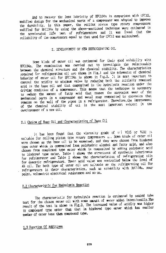
2. DEVELOPEMOO OF NEW REFRIGERATING OIL
Some kinds of ester oil was estimated for their good solubility with
HFC134a. The examination was carried out to investigate the relationship
between the chemical structure and the chemical stability. The characteristics
required for refrigerating oil are shown in Fig.l and the schematic of chemical
behavior of ester oil for HFC134a is shown in Fig.2. It is most important to
control the acidity to minimum value by reducing roth the initially remained
acid in the base oil and that comp:lsi ted in the hydrolysis reaction under the
driving condition of a compressor. This means that the technique is necessary
to reduce the amount of fattY acid that causes the corrosion wear of the
mechanical parts in a compressor and metal soap composi ted by corrosion that
remains on the wall of the pipes in a refrigerator. Therefore, the improvement
of the chemical stability of oil is the most imPJrtant subject in the
developement of a new oil.
2.1 Choice of Base Oil and Characteristics of Base Oil
It has been foWJd that the viscosi r.y grade of oil VG15 or VG32 is
suitable for rolling piston type rocary compressors 3). Some kinds of ester oil
were chosen as the base oil to be examined, and they were chosen from hindered
type ester which is composi ted from polyhydric alcohol and fatty acid, and also
chosen from complexed type ester which is COIUIXJSi ted by adding polybasic acid
to hindered type ester. Table 1 shows the structures of synthetic luburicants
for refrigerator and Table 2 shows the characteristics of refrigerating oils
for domestic refrigerators. Their acid value was controlled below the level of
AB oil. The both type of ester oil are sul table as the refrigerating oil for
refrigerators in their characteristics, such as solubility with HFC134a, PJUr
PJint, volumetric electrical resistance and so on.
2.2 Characteristic for Hydrolysis Reaction
The characteristic for hydrolysis reaction is estimated by sealed tube
test for the chosen ester oil with some amount of water added intentionally.The
result of the test is shown in Fig.3. The increased value of acidity was higher
in complexed type ester than that in hindered type ester which has smaller
number of ester base than complexed type.
2.3 Function Of Additives
828
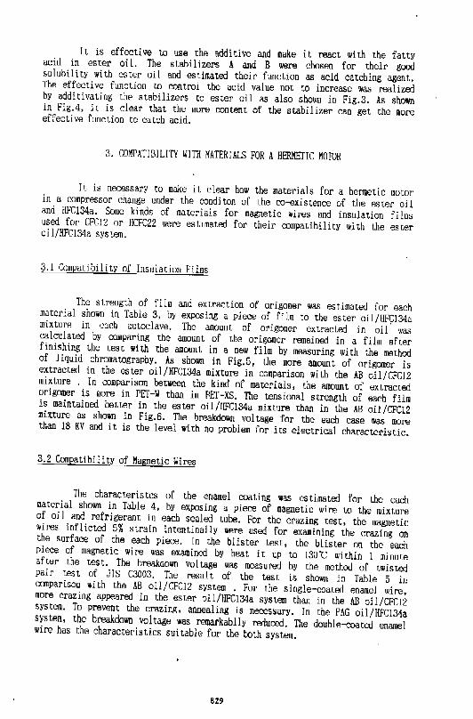
It is effective to use the additive and make it react with the fatty acid in ester oil. The stabilizers A and B were chosen for their good solubility with ester oil and estimated their function as acid catching agent. The effective function to control the acid value not to increase was realized by additivating the stabilizers to ester oil as also shown in Flg.3. As shown in Fig.4, it is clear that the more content of the stabilizer can get the more effective ftmction to catch acid.
3. \1lMPATIBILITY WITII MATERIALS FOR A HERMEriC MOTOR
It is necessary to make it clear how the materials for a hermetic motor in a compressor change under the conditon of the co-existence of the ester oil and l!FC134a. Some kinds of materials for magnetic wires and insulation films used for CFCl2 or l!CFC22 were estimated for their compatibility with the ester oll/HFC134a system.
3.1 C<Jmpatibility of Insulation Films
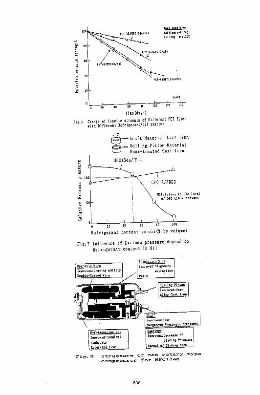
The strength of film and extraction of origomer was estimated for each material shown in Table 3, by exposing a piece of film to the ester oil/HFC134a mixture in cacb autoclave. The amount of origomer extracted in oll. was calculated by comparing the amount of the origomer remained in a film after finishing the test with the amount in a new film by measuring with the method of liquid chromatography. As shown in Fig.5, the more amount of origomer is extracted in the ester oil/HFC134a mixture in comparison with the AB oil/CFC12 mixture . In comparison between the kind of materials, the amount of extracted origomer is more in PE'Hi than in Pfl'-XS. The tensional strength of each film is maintained better in the ester oi l/HFC134a mixture than in the AB oil/CFCl2 mixture as shoiMl in Fig.6. The breakdown val tage for the each case was more than 18 KV and it is the level with no problem for its electrical characteristic.
3.2 Compatibility of Magnetic Wires
The characteristcs of the enamel coating was e.stimated for the each material shown ln Table 4, by exposing a plec..'e of magnetic wire to the mixture of oil and refrigerant in each sealed tube. For the crazing tesL, the magnetie wires inflicted 5% strain intenr.inally were used for examining the crazing on the surface of the each piece. In the blister test, the blister on the eaC'.h piece of magnetic wire was examined by heat it up to 130"C within l minute after the test. The breakdown voltage was measured by the method of twisted palr test of JIS C3003. The result of the test is shown in Table 5 in comparison with the AB oil/CFC12 system . For the single-coated enamel wire, more crazing appeared ln the ester oll/HFC134a system than in the AB oil/CFC12 system. To prevent the crazing, annealing is necessary, In the PAG oil/HFC134a system, the breakdown voltage was remarkablly reduced. The double-coated enamel wire has the character is ties sui table for the t.oth system.
829
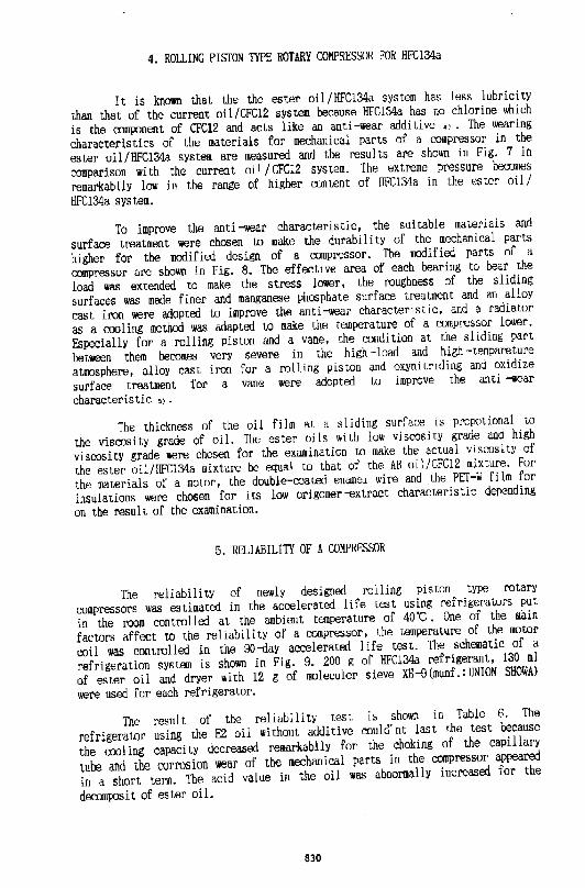
4. RO!l.ING PISTON TYPE ROTARY COMPRESSOR FOR HFC134a
It is known that the the ester oil/I!FC134a system has less lubricity
than that of the current oil/CFC12 system because HFC134a has no chlorine which
is the comp.:ment of CFC12 and acts like an anti-wear additive •l. The wearing
characteristics of the materials for mechanical parts of a compressor in the
ester oil /HFC134a system are measured and the results are shown in Fig. 7 in
comparison with the current oil I CFC12 system. The extreme pressure becomes
remarkablly low in the range of higher content of HFC134a in the ester oil/
HFC134a system.
To improve the anti-wear characteristic, the suitable materials and
surface treatment were chosen to make the durability of the mechanical parts
higher for the modified da9ign of a compressor. The modified parts of a
compressor are shown in Fig. 8. The effective area of each bearing to bear the
load was extended to make the stress lower, the roughness of the sliding
surfaces was made finer and manganese phosphate surface treatment and an alloy
cast iron were adopted to improve the anti -wear characteristic, and a radiator
as a cooling methoo was adapted to make the temperature of a compressor lower.
Especially for a rolling piston and a vane, the condition at the sliding part
between them becomes very severe in the high -load and high -tempareture
at1110sphere, alloy cast iron for a rolling piston and oxyni triding and oxidize
surface treatment for a vane were adopted to improve the anti -wear
characteristic >l •
The thickness of the oil film at. a sliding surface is propotional to
the viscosity grade of oil. 1he ester oils ~i th low viscosity grade and high
viscosity grade were chosen for the examination to make the actual viscosity of
the ester oil/HFC134a mixture be equal to that of the AB oil/CFC12 mixture. For
the materials of a mawr, the double-coated enamel wire and the PET-w film for
insulations were chosen for its low origomer-extract characteristic depending
on the result of the examination.
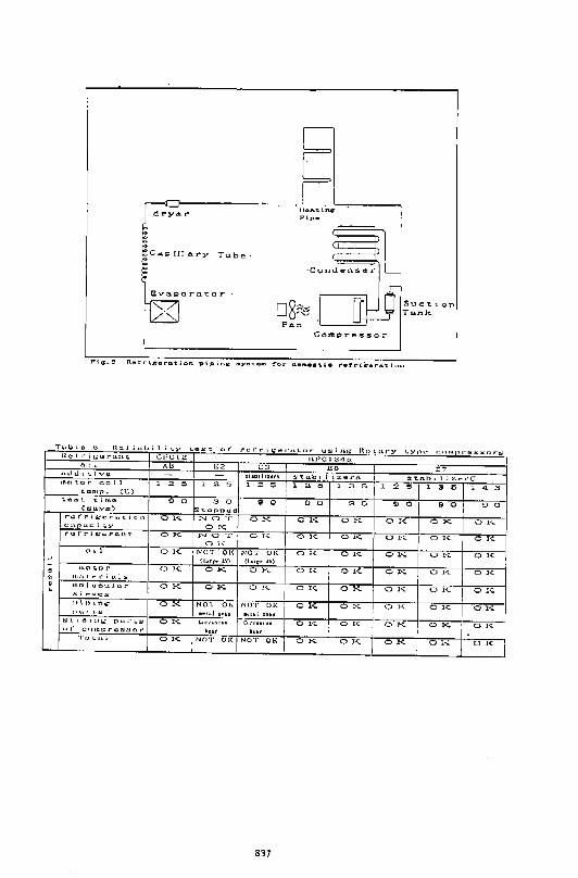
5. RELIABILITI OF A COMPRESSOR
The reliability of newly designed rolling piston type rotary
compressors was estimated in the accelerated life test using refrigerators put
in the room controlled at the ambient temperature of 40"C. One of the main
factors affect to the reI iabi li ty of a compressor, lhe temperature of the motor
t:oil was mntrolled in the 90-tlay accelerated I ife test. The schematic of a
refrigeration system is shown in Fig. 9. 200 g of HFC134a refrigerant, 130 ml
of ester oil and dryer with 12 g of moleculer sieve XH-9(munf.:UNION SHOWA)
were used for each refrigerator.
The result of the reliabi 1 i ty test is shown in Table 6. The
refrigerator using the E2 oil without addi ti vc could' nt last the test because
the cooling capacity decreased remarkablly for the choking of the capillary
tube and the corrosion wear of the mechanical parts in the compressor appeared
in a short term. The add value in the oil was abnormally increased for the
decomposit of ester oil.
830
The refrigerator using the low viscosity grade of E3 oil with additive stabilizer A could last the 90-d.ay life test, however, it was not enough because the acid value was increasoo, the corrosive wear at the sliding parts between the rolling piston and the vane, and between the shaft and the bearing appeared, or the metal soap was found,
The refrigerators using the high viscositY grade of E6 oil with additive stabilizer A or E:7 oil with stabilizer C could last the 90-rlay life test in a normal condition that the acid value was not increased to the level of problem and no fault was found in the parts of each refrigeration cycle and compressor. The test result shows that the reliability approximately equal to that of the CFC12 system can be maintained in the HFC134a system by using the ester oil of higer viscosity grade with the stabilizer as the additive and controlling the temperature of motor coil below 135"C.
6,SUMMARY
The technology for rolling piston type rotary compressors used in refrigerators adapted to HFC134a has developed.
(1) The hindered type ester oil with the e!XJXY addi tlve as the acid-catch agent which has enough anti -hydrolysis reaction and refrigerant -proof characteristic has developed as the refrigerant oil for the HFC134a refrigeration system.
(2) The sui table materials for the insulation film and magnetic wire has been found by testing their compatibility with the ester oil/HFCl34a system.
(3) The anti --wear materials, surface treatment and the radiator structure have dveloped to improve the durability of the mechanical part in a compressor.
However,this test only could estimate the reliability of compressors under a certain limited condition. So we are now continuing extend examination to adapt the above-mentioned technology to the various actual use.
REFFERENCES
l) K. Matsubara, Y. Ishii, M. watanabe, H. Matsuzaki, ~CFC Issue in Hitachi," Hitachi Review Vol. 39,(1990)
2) S. Kitaichi, S. Sate, R lshidoya, T. Machida, "Tribologocal Analysis of Metal Interface Reactions in Lubricant Oils /CFC12 and HFC134a System," ASHRAE -Purdue CFC Conference, Purdue University,(l990)
3) H. Kosokaffi, K. Fndoh, H. Iwata, H. Hata, M. Fujiwara, "Developement of High Efficiency Rotary Compressor for fumestic Refrigerator Using HFC134a," 25th Japanese Joint Conference on Air--conditioning and Refrigeration,89, (1991)
831
4) Y. Homma, S. Komatsuzald, T. Iizuka, "Wearing Characteristic under the Condition of Freon/Oil co-existence," Japan Tribology Conference,(1991)
5) Y. Nakagawa, Y. Kamitsuma, T. Iizuka, K. Ikeda, "Selection of Friction Materials Used in Compact, High Performance Invertet Controled - Rotary Compressors," International Compressor Engineering Conference at Purdue, (1990)
832
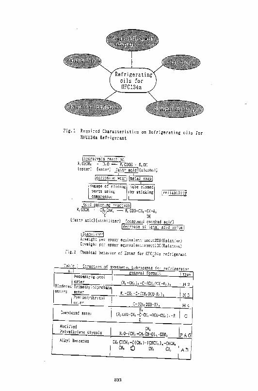
Fig.l Required Characteristics on Refrigerating oils for llFCl34a Refrigerant
\Hydrolysis reaction\ R, COOR, • H, 0 R, COOH + R, OH [ester] (water] \farw acid) (alcohol)
) 1 I carros ion wear I (metal soap I I
!damage o~ ~liding pi:.rts using compressor
\Acid catcc:n~; reaction) R, GOOH + CH, CrR, ~ R, COO-Cn, -CH-R,
'o' oH
( re 1 i ab iIi Uj
[fatty acid)[stabilizer) (co~pound catched acid) \decrease of rotai ac:d va!uel
)Staoi!Jzd A:welg!n per epoxy eq~ivalen::aooL::200(ReLHive) C:weight per epo~J' equ:valem:aoout!OO(Rela!lve)
i"ig.2 Chemical beh<tvior of Ester for H?q3'a refrigerant
Table 1 <·-uctres of S\'ntheuc Lub•1canu for refrige">!Or -·· oi I I genera 1 formula I type J heopenT..yJslycol I (R, -CH,), -C- (CH, OCO-R,),
'r 1 ester 'H2 Hindered) Tricethylolpl'opanej
esters ~ster R. -CH, -C- (CH, OCO-R,), IH3 I Pentaernhr: '"I I esre!" I C- CCH, OCO-R), IH4
I R,
I Camp I exec' eSler (R, GOO-CH, -~-CH, -OCO-CH,), -R c
R
Modi;'ied
I I
~H,
IPAG, Po!yalkl·lene Glycols R, 0- [CH, -CH, CH-0] ,-COR, Alkyl Benzenes I CH,~HCH,-C(CH,)-[yHCli,L-~HCH, I
CH, 0 CH, CP., AB
833
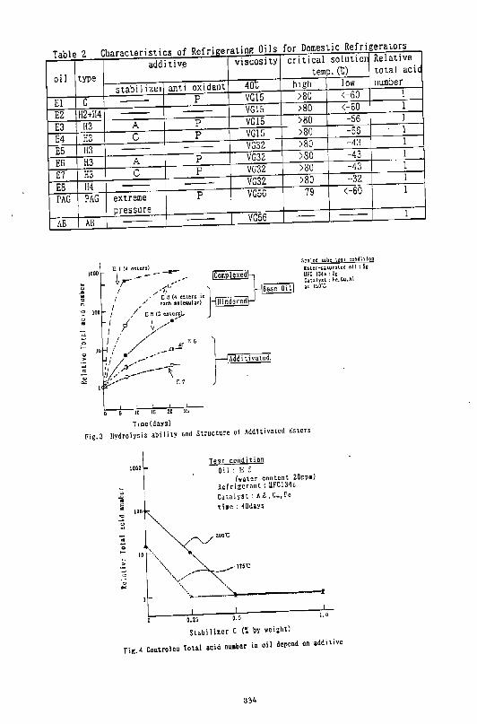
Table 2 Characteristics of Refrigerating Oi Is for Domestic Refrigerators
oi 1
El EZ E3 E4 E5 E6 E7 E8 PAG
AB
addi tiv~ type
stabi 1 i zer anti oxidant
c --- p
H2+114 --- ---113 A p
113 c p
113 --- ---113 A p
H3 c p
ll4 --- ---PAG extreme p
pressure AB --- ---
ID !.!i 2.D 25
Ti~c(days)
viscosity
40t VG15 VG15 VG15 VG15 VG32 VG32 VG32 VG32 VGSG
VG56
critical solutioJ temp. (t)
high low >80 <-60 >80 <-60 >80 -56 >80 -56 >80 -43
>SO -43 >80 -43 >80 -32
79 <-60
-- ---
S~;:ah:d tulle ~est cgntfition
htt!r-:>ilwr:u.~:d oii;Sc
111-"'C l3~a = 2t Ci1Ulys1.; h~.~u,Al
11.~ l!iO"C
Fig.3 Hydrolysis abilitY and Structure of Additivatcd Esters
" " .... ,.
" " "'
I(J[IO
100
Test condition
Oi I : E 5 (wotcr content 20ppm)
Refrigcrnnt: lii'Cl34a
Catalyst: A£ ,Cu,l'c
t i~c : 40days
2.DO"C
......... · ... ---~--------r o.~s o.s 1. o
Stabilizer C (~by weight)
Fig.4 Controlcd Total acid nu•b•r in oil depend on addi tivc
334
Relative total aciq number
1 1 1 1 l l l l l
1
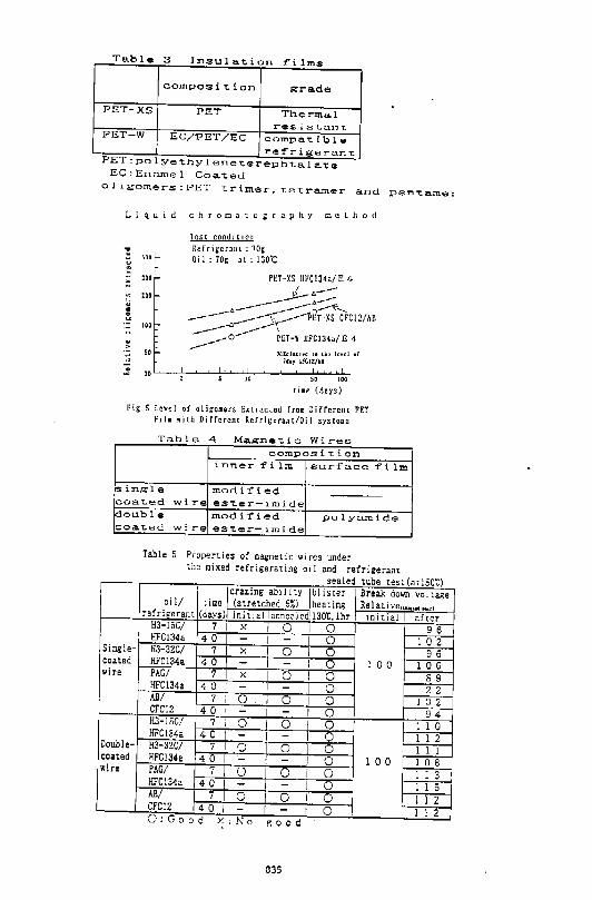
Table 3 Insulation films
composition grade
PET-XS PET Tl"ler-mo.l res i sta11 t.
PET-W EC/1?ET/EC oompa.T.ible refr-i.ger-an"t:.
PEr:po!ye-r.hylene-r.er-ephta.la.te EC:Enrunel Coa-ced
oligomers:PET trimer.Le~ramer and pen~amer
Liquid chromatography method
... 500
" ~ '" " "' " !
100
;;: ;; " ..
" "'
Test condition Refrigerant; 70~: Oil:70g at:IJO·c
l'I:T-XS IIFGI34a/E 4
~~::::: ----"~~CFC12/AO ~ PET-W IIFCI31o/E 4
~a~Jui'fc: u Llu~ JtytJ .r 71.1Ji;fCI2/AII
JQ so 100
time (dan)
Fig_S Love! of oligomers E>tractcd from Different PET Fila with ,Diffl!rent Rcfri~;:~:r~un/Oil syste11s
T ble 4 a. Magne"t.iC Wires composition
inner film surface
single modified coaLed wire esLer~irnide
film
~ouble modified polya.m.ide coaT.ed wire esLer-irnide
Table 5 Properties of ma<:netic wires under the mixed refrigerating oil and refrigerant
sealed tube test(atlSOt) crazing abll i tY I blister Break down voltage
oil/ time (stretched 5~) heating Re l at i ve(utjn..: 1111.1r) refrigerant (days) init1el annealed,13Dt,lhr 1ni tial after
H3-15C/ 7 X I 0 I 0 9 6 HFC134a 40 - I - I 0 1 0 2 Single- H3-32C/ 7 I X 0 -, 0 9 6
coated HFC134a 40 - - i 0 1 0 0 1 0 6 wire PAG/ 7 I X 0 I 0 8 9
HFC134a 4 0 I - - I 0 2 2 AB/ 7 I 0 I 0 T 0 1 0 2 CFC12 40 I - I - I 0 94 H3-15C/ 7 i 0 I 0 I 0 1 1 0 HFC134a 4 0 - I - I 0 1 l 2 Double- H3-32C/ 7 I 0 0 I 0 l 1 1 coated HFC134a 40 - I - I 0 l 0 0 l 0 8 wire PAG/ 7 0 0 I 0 l 1 3 HFC134a 4 0 - ' - I 0 1 1 5 AB/ 7 0 0 I 0 1 1 2 CFC12 40 I I i 0 l 1 2 O.Good x.l':o good
035
-= .. •• " .,
"' !! •• ., " " ... ., <0 .. .. " zo ""
!--- PET-IS(UPCI3h/E4)
Ten ca .. hioo lerritcnnt:70c
Oil:10l at: 130t
~::::::-t_--
1 ~rET-lS(CFCIZ/Al) "'(
r>.T-r(CI CI2/Ail
~~~ rt.T~J(Urca :Ha/E4>
iQ SO HID lZO
Timc(days)
fig.6 Chango of Tensile strong\h of Different PET films
with Different Refrigerant/Oil systems
., >
....._:) a-Shaft Material Cast Iron
~-Rolling Piston Material
~ Heat-treated Cast Iron
IIFCJ34a/E 4
·---··-·---·r-··--··.6 CFC12/AB60
~H.!:!hliv~: to ~he level or sox CFC12 c:Dn't.cJJt
0 ~o-----zLo----~4o~~~s~o----~ao~--~,~o~o---
Rcfrigerant content in oil(% by volume)
Fig. 7 Influence of Cxtreme pressure depend on
Refrigerant content in Oil
Refrieea.tins Qi l l•PrQved:Che~~ical
stn.bili't.y Ester-+Additive
Insulation Fillh
lmproved:Olil!:omer::s;
e~t.ra.ct.ion
Fig_S Structu~e of new ro~ary ~ype
cornpresso~ rOr HFC134a
836
r-~C:}-------------------~IIO&~in~~~-------, P"ip•
T~1\.l 1 o G n~l ii..ll)il i'l;.y t.~.S't. "" r-~Fri.~:er'n'Lnr u:;inG:" ltu L;\ry 'I..YTh~ [::UIIIJll"l:!l~~rlr;s ne1 I'" i u; !.!I f"' ~lit c.. cr:-c1.2 ll.r:"Cl :,'lol'l.~ (')i I A~ E2 1:3 l!:G !:7 n<JcJ It. i VI; st&bTIIurA $'t'-Lhi l iZ.I:!Il""!\ $t.C.h I} i~ei"C '"'t' t.or ""' l 1 2 " 1 2 " 2 " 1 2 " 1 3 5 1 2 !5 1 " 5 1 <I " t.en1p. (I:)
t.'l!.i5!.. ~ i rrlll!! s 0 " 0 s 0 " 0 s 0 "' 0 ,. 0 "' 0 {GIU..Yos) ~tonp~d r~t'r- i ll:'croi.l; i c 1\ 0 K N 0 T 0 1-<- 0 1<- 0 1<- 0 I-<. 0 K 0 I~ ca)"Juci
-~ 0 r<; ~uf'rii:"o;::r'.('I,U~ 0 K NO T 0 '" 0 '"' 0 J<; 0 I<; 0 K 0 '"' 0 '"" oo l OK N(JT 01< NOT "" 0 K 0 K 0 K 0 1-<- 0 K
ll .. fj•,I.V) (lllr~t ... ~, m('ll',or 0 '"'- 0 K 0 K 0 K 0 K 0 '"'" 0 K 0 K • IIIUt.~('iu,ls
• mnlod;eulu.r .. 0 K 0 K 0 1'<. 0 I<;. 0 l-<- 0 K 0 K 0 1<. ~i~vcs
pi. n 11':1~ 0 '""- NO"I 01< NOT OK 0 1<. 0 I< 0 K 0 K 0 K •t:tld ~~~~~~ ~l.lll Sl\4fojl
"' LdiHI:: pttr'l,~ 0 I<;. Clii!I'IIS\111! ~•I'TIUI.Iolll 0 K 0 K 0 1-<- 0 1<. 0 1~ uf COII'II~rC.!ii.:!::I:Or" 'l.~:..t ItcH Tq r..ttl 0 1<. I NOT en: NOT "" 0 1'<. 0)<;. 0 K 0 1-<- 0 J<.
837
DEVELOPMENT OF HIGH EFFICIENCY ROTARY COMPRESSOR FOR DOMESTIC REFRIGERATOR USING HFC-134a
Hirokatsu Kosokabe, Kazuhiro Endoh Mechanical Engineering Research Laboratory, Hitachi, Ltd., Ibaraki, Japan
Hiroshi Iwata, Dr., Hiroaki Hata Tochigi Works, Hitachi, Ltd., Tochigi, Japan
Mitsuru Fujiwara, Dr. Muroran Institute ofTechnology, Hokkaido, Japan
ABSTRACT
In response to the trend for phasing out CFCs, we have developed a high efficiency HFC-134a rotary compressor, whose total adiabatic efficiency is 9% higher Lhan that of the present CFC-12 one. This paper describes the causes for the usual poor performance of rotary compressors using HFC-134a and explains how we improved the performance.
INTRODUCTION
CFCs will be phased out in the mid 1990s. Since CFC-12 is the usual refrigerant for domestic refrigerators, alternative refrigerants urgently need to be developed. The most promising alternative seems to be HFC-134a. However, it has been reported that when HFC-134a is substituted for CFC-12, the performance of refrigerators and compressors decreases [1,2]. Our initial test of rotary compressors using HFC-134a also showed a large drop in performance. Therefore, we investigated the causes of the decrease in performance and developed ways to improve performance. As a result, we have developed a high efficiency rotary compressor using HFC-134a.
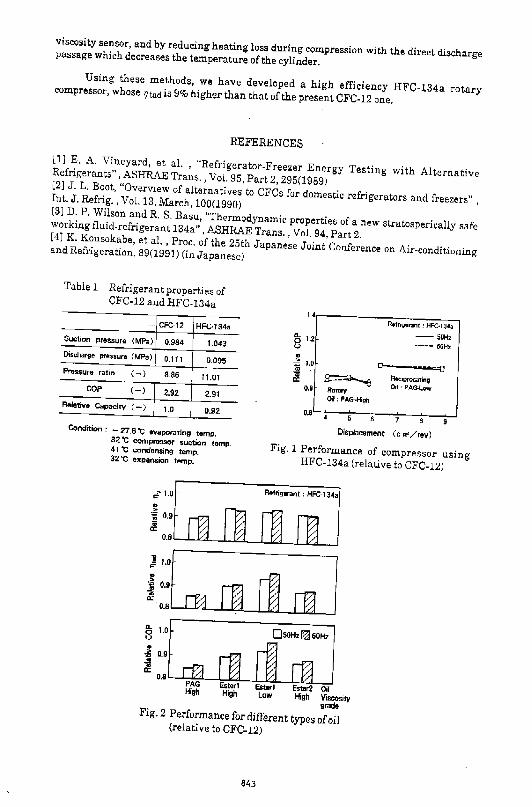
HFC-134a REFRIGERANT PROPERTIES The refrigerant properties ofCFC,12 and HFC-134a are compared in Table 1 for the same temperature [3]. Since HFC-134a has a lower suction pressure and a higher discharge pressure than CFC-12, the pressure ratio of HFC-134a is 24% higher than that of CFC-12. The theoretical coefficient of performance (COP) on the Mollier chart ofHFC-134a is similar to that of CFC-12 and this indicates no drop in efficiency using HFC-134a. On the other hand, the refrigerating capacity of HFC-134a is 8% smaller than that of CFC-12 and compressors using HFC-l34a need a larger displacement to maintain the same capacity.
INITIAL TEST
Since HFC-134a is not compatible with the mineral oil or alkylbenzen oil used with CFC-12, it needs a new oil such as polyalkylene glycol (PAGJ oil or ester oil. For the initial test, we used HFC-134a and PAG oil for a compressor calorimeter test using the rotary and reciprocating compressors designed for CFC-12. For CFC-12, high viscosity grade (VG) oil is
839
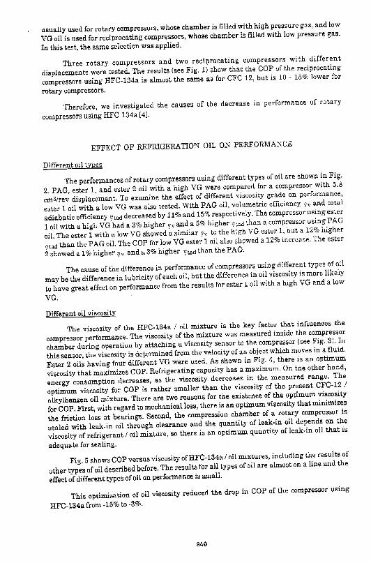
usually used for rotary compressors, whose chamber is filled with high pressure gas, and low
VG oil is used for reciprocating compressors, whose chamber is filled with low pressure gas.
In this test, the same selection was applied.
Three rotary compressors and two reciprocating compressors with different
displacements were tested. The results (see Fig. 1) show that the COP of the reciprocating
compressors using HFC-134a is almost the same as for CFC-12, but is 10 - 15% lower for
rotary compressors.
Therefore, we investigated the causes of the decrease in performance of rotary
compressors using HFC-134a (4].
EFFECT OF REFRIGERATION OIL ON PERFORMANCE
Different oil types
The performances of rotary compressors using different types of oil are shown in Fig.
2. PAG, ester 1, and ester 2 oil with a high VG were compared for a compressor with 5.8
cm31rev displacement. To examine the effect of different viscosity grade on performance,
ester 1 oil with a low VG was also tested. With PAG oil, volumetric efficiency r;v and total
adiabatic efficiency r; lad decreased by 11% and 15% respectively. The compressor using ester
1 oil with a high VG had a 3% higher '/v and a 5% higher '7tad lhan a compressor using PAG
oil. The ester 1 with a low VG showed a similar 'lv to the high VG ester 1, but a 12% higher
'7tad than the PAG oil. The COP for low VG ester 1 oil also showed a 12% increase. The ester
2 showed a 1% higher ~v and a 3% higher '/tad than the PAG.
The cause of the difference in performance of compressors using different types of oil
may be the difference in lubricity of each oil, but the difference in oil viscosity is more likely
to have great effect on perf~rmance from the results for ester 1 oil with a high VG and a low
VG.
Different oil viscosity
The vi:;;cosity of the HFC-134a I oil mixture is the key factor that influences the
compressor performance. The viscosity of the mixture was measured inside the compressor
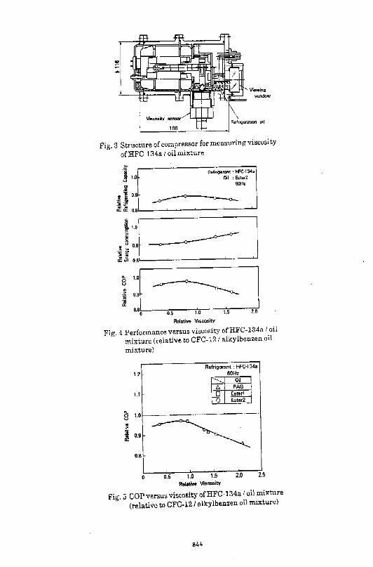
chamber during operation by attaching a viscosity sensor to the compressor (see Fig. 3). In
this sensor, the viscosity is determined from the velocity of an object which moves in a fluid.
Ester 2 oils having four different VG were used. As shown in Fig. 4, there is an optimum
viscosity that maximizes COP. Refrigerating capacity has a maximuiiL On the other hand,
energy consumption decreases, as the viscosity decreases in the measured range. The
optimum viscosity for COP is rather smaller than the viscosity of the present CFC-12 I
alkylbenzen oil mixture. There are two reasons for the existence of the optimum viscosity
for COP. First, with regard to mechanical loss, there is an optimum viscosity that minimizes
the friction loss at bearings. Second, the compression chamber of a rotary compressor is
sealed with leak-in oil through clearance and the quantity of leak-in oil depends on the
viscosity of refrigerant I oil mixture, so there is an optimum quantity of leak-in oil that is
adequate for sealing.
Fig. 5 shows COP versus viscosity ofHFC-134a I oil mixtures, including the results of
other types of oil described before. The results for all types of oil are almost on a line and the
effect of different types of oil on performance is small.
This optimization of oil viscosity reduco::d the drop in COP of the compressor using
HFC-134a from -15% to -3%.
840
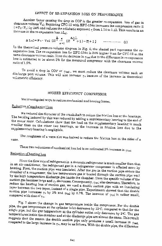
EFFECT OF RE-EXPANSION LOSS ON PERFORMANCE Another factor causing the drop in COP is the greater re-expansion loss of gas in clearance volume V cl· Replacing CFC-12 with HFC-134a increases the compression ratio IT ( =:oPd /P5 ) by 24% and reduces the adiabatic exponent" from 1.14 to 1.12. This results in an increase in there-expansion loss ~Lei· '
l. I< ~ L!.Lcl=Ps· Vel CIT~-- (TI "-:-1}-IT+l] I< -l ' (1)
In the theoretical pressure-volume diagram in Fig. 6,' the shaded part represents the reexpansion loss. There-expansion loss for IIFC-134a is 34% higher than for CFC-12 at the same clearance volume ratio. Thus the decrease in '/lad due to the difference in re-expansion loss is estimated to be about 2% for the measured compressor with the clearance volume ratio o£1.5%.
To avoid a drop in COP or r;tad , we must reduce the clearance volume such as discharge port volume. This will also increase '/v because of the increase in theoretical volumetric efficiency.
HIGHER EFFICIENCY COMPRESSOR
We investigated ways to reduce mechanical and hen.ting losses. Reduction of mechanical loss
We reduced the diameter of the crankshaft to reduce the friction loss at the bearings. The bending induced by this was reduced by adding a supplementary bearing to the end of the motor rotor, Calculations show that the load on the supplementary bearing is much smaller than on the other two bearings, so the increase in friction loss due to the supplementary bearing is negligible.
The roughness of a vane slot was halved to reduce the friction loss at the sides of a vane.
These two reductions of mechanical loss led to an estimated 3% increase in '/lad, Reduction of heating loss
Since the flow rate of refrigerant in a domestic refrigerator is much smaller than that in an air-conditioner, the refrigerant gas in a refrigerator compressor is affected more by heating. First, the suction pipe was insulated. After the gas in the suction pipe enters the chamber of a compressor, the low temperature gas is heated through the suction pipe wall by the high temperature discharge gas inside the chamber. Thus the specific volume of the suction gas becomes large and 7Jvdecreases. Consequently, '?tad also decreases. Therefore, to reduce the heating loss of suction gas, we used a double suction pipe with an insulating layer between the two pipes, instead of a single pipe. Experiments showed that the double suction pipe increases r;v by 2% and '7tad by 0.7%. The increase of '7tad is rather small, com pared with that of '7 v·
Fig. 7 shows the change in gas temperature inside the compressor. For the double pipe, the gas temperature at the cylinder inlet decreases by I2oC, compared to that for the single pipe, but the gas temperature at the cylinder outlet only decreases by zoe. The gas temperatures inside the chamber and at the discharge pipe are almost the same. This result suggests that the rea~on the ~ouble suction pipe only produces a small increase in 'ltad, compared to the large mcrease m 7Jv, may be as follows. With the double pipe, the difference
841
in temperature between the suction gas and the cylinder wall is larger and the suction gas is
more subject to heating. This increases indicated work and reduces indicated efficiency.
Therefore, to obtain a large increase in ?tad, we should lower the temperature of the
cylinder itself and reduce the quantity of heat transferred to the suction gas.
As Fig. 8 shows, in the present compressor, the high temperature gas discharged from
a cylinder goes through the silencer next to the cylinder and is led to the motor side. As a
result, the cylinder is heated. During suction, the low temperature suction gas is heated and
expanded, thus ? v decreases. At the early stage of the compression process, as previously
described, the gas receives heat from the cylinder wall and indicated work becomes large
and indicated efficiency decreases. Therefore, as shown in Fig. 8, we chose a direct discharge
passage which decreases the quantity of heat transferred to the cylinder. The high
temperature discharge gas is led directly to the outside of the chamber. Then it is cooled by
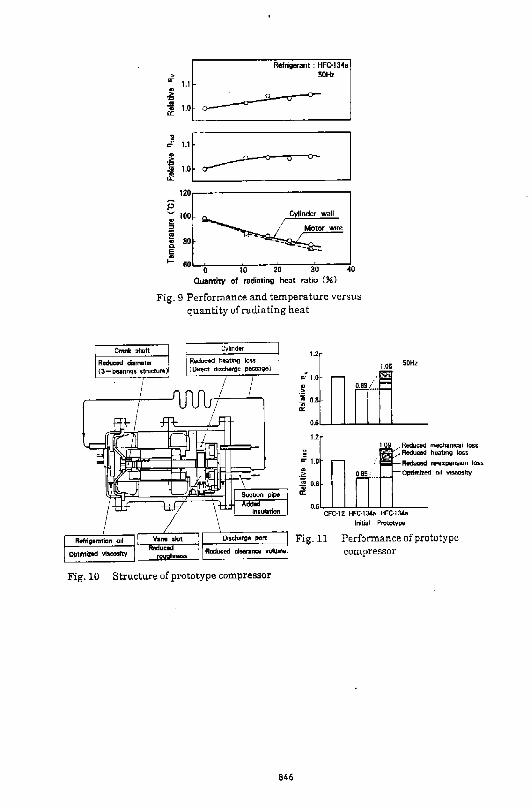
passing it through the radiating pipe and is returned to the inside of the chamber. With the
change in length of the radiating pipes, we examined the performance versus the quantity of
radiating heat (see Fig. 9). The quantity of radiating heat is represented as the percentage
of the consumption energy. As shown in this figure, as the quantity of radiating heat
increases, the temperature of the cylinder wall and motor wire decreases and '/ v increases
significantly. ?Lad also increases significantly but it has a saturation point. Since in the
study of refrigeration oil, HFC-134a I oil mixture viscosity increased as the temperature
decreased, ?tad is likely to be influenced by the increasing viscosity of the mixture. This
method increases~" by 4% and ?tad by 5% for a temperature decrease of l5°C.
PERFORMANCE OF PROTOTYPE COMPRESSOR USING HFC-134a
Structure
We constructed a prototype compressor incorporating all of the improvements
described above; namely, optimized oil viscosity, reduced clearance volume at discharge
port, reduced crankshaft diameter, reduced vane slot roughness, insulated suction pipe, and
added direct discharge passage. The structure of this prototype is shown in Fig. 10.
Performance
The performance of the prototype compressor is shown in Fig. 11, compared with the
present compressor using CFC-12 and the initial test using HFC-134a. ~tad of the prototype
compressor is 9% higher than that of the present compressor using CFC-12. This is a 24%
increase over the initial test and is close to the sum of performance increases expected from
each improvement. Although it is difficult to distinguish individual contributions, they are
probably; 43% by optimized oil viscosity, 15% by reduced clearance volume, that is, reduced
re-expansion loss, 27% by reduced heating loss, and 15% by reduced mechanical loss.
The ?v of the prototype compressor is 5% higher than that of the present one. This
results from the optimized oil viscosity, reduced clearance volume, and reduced heating loss.
CONCLUSION
When HFC-134a is substituted for CFC-12 in a rotary compressor, the performance
decreases. The main causes of this performance decrease are the higher viscosity of the
HFC-134a I oil mixture, and the greater re-expansion loss of gas in clearance volume.
The performance can be improved by optimizing the oil viscosity by directly
measuring the viscosity of the HFC-134a I oil mixture inside the compressor chamber with a
842
viscosity sensor, and by reducing heating loss during compression with the direct discharge passage which decreases the temperature of the cylinder. Using these methods, we have developed a high efficiency HFC"134a rotary compressor, whose 'ltad is 9% higher than that ofthe present CFC-12 one.
REFERENCES [1] E. A. Vineyard, et a!. , "Refrigerator-Freezer Energy Testing with Alternative Refrigerants", ASHRAE Trans., Vol. 95,Part 2, 295(1989) [2) J. L. Boot, "Overview of alternatives to CFCs for domestic refrigerators and freezers" , Int. J. Refrig., Vol. 13, March, 100(1990) [3) D.P. Wilson and R. S. Basu, "Thermodynamic properties of a new stratosperically safe working fluid-refrigerant 134a", ASHRAE Trans., Vol. 94, Part 2. [ 4] K. Kousokabe, et al. , Proc. of the 25th Japanese Joint Conference on Air-conditioning and Refrigeration, 89(1991) (in Japanese)
Table 1 Refrigerant properties of CFC-12 and HFC-134a
.. CFC-12 HFC·134a
Suction PfOSsufe (MPal 0.984 1.043 Discharge pressure ( MPa) 0.111 0.095 Pressure ratio (-) 8.86 11.01
COP (-) 2.92 2.91 Relative Capacity ( -) 1.0 0.92
Condition ~ ~ 27.6 't evaporating temp. 32 "C compressor suction temp. 41 "C condensing temp. 32 "C expansion temp.
~ 1,0 ., ~ 0.9 -;;; a:
;:[: PAG High
rn Ester! High
u.-------------, ~ 1.2 <..> ., ·~ 1.0 ., -;;; a:
O.B ~ Rot.,ry Oil o PAG-High
Refr•ge1'11nt: HFC·1:34.a --SOH< ---- 60H>
o>----=-=-'tl Ret:•PrnQ.ting Od: PAG-Low
0.6'--':---=---~--=--~---:-...J
Displacement ( c m' /rev)
Fig. 1 Performance of compressor using HFC-l34a (relative to CFC-12)
Rolrigofant : HFC·I34a
Oil Viscosiry grndo
Fig. 2 Performance for different types of oil (relative to CFC-12)
843
Viewing w1ndow
Fig. 3 Structure of compressor for measuring viscosity
ofHFC-134a I oil mixture
·i" ! 1.0
"' ... ~ ~ 0.9
i~
Refngsrant · HFC-ta•a Oil : Ester2
60Hz
"'"' o.a.'-----'---....._ ___ _._ ___ w
t 1.0r I .uog~~ j! 0.81'-------'~---'------.J....J
iJ:-~ I 0 0.5 1.0 1.5 2.0
Relative Viscosity
Fig. 4 Performance versus viscosity ofHFC-134a I oil
mixture (relative to CFC-121 alkylbenzen oil
mixture)
1.2
1.1
8 1.0
j~. ,;:0.9 -~
0.8
o.s 1.0 1.5 2.0 2.5 Relllliva Viscosity
Fig. 5 COP versus viscosity ofHFC-134a I oil mixture
(relative to CFC-121 alkylbenzen oil mixture)
844

B
Vcl P-V Diagram
Ld> : Theoretical adiabatic compression power
("' Area ABCOl ll.Ld : AHxpanSion lo$S
("'Area CDE)
v
0 15~-----------------------, -~
Clearance volume ratio Ve~ /Vth ( 9-1)
Fig. 6 Comparison between CFC-12 and HFC-134a re-expansion loss
e .. " .. 8. E ~ .. "'
160
uo
120
100
BO
BO
40
20
' ' I
' ' '
I I
(j) Suction pipe. @ Chamber inside
Refngen;mt : HFC-134a 50Hz
-'-0--- Sin~le pipe
~ Double ~:~ipe
® Cvlindor inlet. ® Cviindor outlet ® Dischargo pipe
Fig. 7 Change in gas temperature inside compressor
D•sc:harQa gas passage Conventional--~---)" Direct -----..
Fig. 8 Passage of discharge gas
845
Refrigerant : HFG-1 34• .; 50Hz .. 1.1 -~ -~ "';;1.0~
"'
..... ~ ~o-1.0 r:r--
; 1.1r
~ -~----------------~ 120,-------------..,
e 100
~ I!! .a • ; 80 -0. -li
1- 60 0 10 20 30 40
Ouantity of radiating heat ratio(%)
Fig_ 9 Performance and temperature versus quantity of radiating heat
1.2
~1.0
" .2: ~ 0.8 a:
1.05 50Hz
O.lit__L.....-'--'---'--'--'----
1.2
Fig.lO Structure of prototype compressor
846
1 09 Reduced rneehamcal loss Redue8d h~t1ng loss
R~ re-e.~~;PillliiDn lo:s:s OptimizMI c1l v~ity
Initial PrototvPEJ
Fig.ll Performance of prototype compressor
AN EKPER.IHaiTAL INVESTIGATION OF A REF'RIGEXATION COMPfU;SSOR USING IIFC 1:l4a AS A ~lNG SUBSTANCE
Cho Kwang Yeon, Shin Seung Hoon , Balk Woon Yong Central Research &. DeveloJ>IIent Lab.lt-atory, Oa......x> Electronics, Yong Hyon lhng, lncheon, Korea
Cho Cheol Yeon , Ho Jeong Hwan Incheon Works; Dae1.00 Electronics, Ltd. Yong Hvon lhng, Incheon, Korea
A proto type coqpressor using IIFC 134a as a wrl<ing substllllce is designed. As the specific vo)UIIe of IIFC 134a is larger than that of CFC 12. tho. ~~ass fJOIJ rate and capacity are decreased. Reduction of residual gas and suction gas te111perature and i11prove11ent of suction gas passage, ll<:itor efficiency, use of ICAJ viscocity oil are considered to i111prove the perforllaOCe of a IIFC !34a COilpressor. By these IIOdifications, the COl' of ( Coefficient of Perfor.ance ) IIFC 134a co11pressor could be l11proved by 20 %. The results of collpressot" life tests and 0011patibi lity tests pl"acticed with 4 kinds of ester oil are rel>"'"ted.
area of suction 11uffler inlet speed of sound
NOMENCL\ nJR£
v Vd
suction 11uffler vclu.e displacement specific volUJie isentropic uol"k
A c fc L Ls
Q
cut off frequency of suction 11uffler length of suction muffler inlet Attenuation ess f I CAJ rate leakage capacity
v. w.rt W'lo••
"''2 w.s N
energy loss during gas coqpression energy cons!Uiption using 32 est oil energy conS~U~ption using 15 est oi I ,.
difference of enthalpy bet"""n evaporator outlet and inlet
17v
INlliDDUCTION
volt~~~etric effici .. ncy
After the publication of the critical effect of the CFCs on the earth's atllosphere, extensive wrks have been done to searoh for new refrigerant to substl tute for CFCs. CFC 12 has been 1o1idely used as a refrigel'ant in the refrigeration field due to its excellent the~ic properties. che11ical stability, non-toxicity, non-flauability. HFC 134a, although it does not possess all the necessary and sufficient conditions. i-s cur"r'ently being studied to replace the CFC 12 as it has relatively si111lar thei'IIOdy-!lallic properties 1o1ith CFC 12. The proble11s to be solved to use IIFC 13% as a ne1o1 refrigerant ~~ay be listed as follows. (1) Perfo....nce
(2) Develo~nt of new lubricant (3) ~ter!al coapatibility Table 1. It can be said that one of difficult probleiiS of HFC 1348 is a capacity drop resulted fro11 its relatively large specific vol!Uie. (Table 1) Although this capacity drop lilly be easily COIIpensated for by the si11ple increase of diSplace ... nt voi!Uie, it is 110re effective to find ways to increase uss flow rate with current displace~~ent volu.e as it is not always possible to increase displaceftnt vol Ulle and it does not i11ply i11prove11ent of efficiency.
II .:l.h..vo
Q
HFC 134a CFC 12
0. 7 I 1.24 1 0.87 1
As HFC 13% shCAJs very poor 11iscibllity 1o1ith llineral oil, it is necessary to develop new lubricant •iscible with IIFC 134a. Although •uch ""'rk has been done with PAG, polyal ester sh<M: JIIOl"@ possibilitY than PAG in view of hygroscopicity and lubricity. However therul stability, hydrolccical stability, still need to be estillllted for the c011pressor reliability. This study is to reviw easures to iJIPI'OVe a c011pressor perfor.nce, to discuss lubricant problell and 1111terials c011patibility using IIFC 1348 as a wrking fluid.
847
PERFORIWICE
(1 l Mode I C.:.pressor
Bali joint type l"'!Ciprocatil'@ ca.pressor is
used for this study. This IIOdel is widely
applicate<! in the OO.stic refrigeration llal'ket.
Specification is sllllllariaed in Table 2.
(2) Method of approach
Table 2 Specification
Capacity • Bore Displacement motcr outpUt Di11ension * with CFC 12
200 kcal/h 23.5 rill
7.02 cc/rev 175 watt ,P159 x H 170
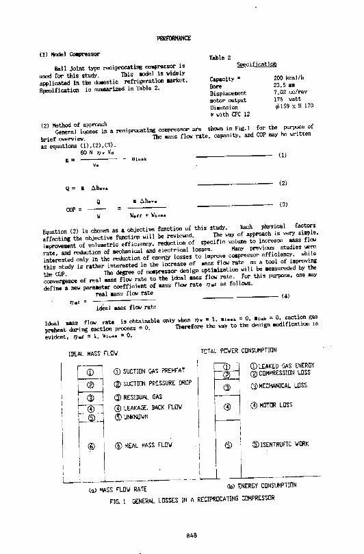
General l0sses in a reciprocating compressor are shown in Fig.l for the purpose of
brief overview. The JllaSS fla; rate, capacity, and COP lllllY be written
as equations ( 1), (2), (:l). 60 N T]v Vd
• = - mtaak (1)
v.
Q= II Ll.hova (2)
Q • Ll.h. ••
COP.:: = (3)
'II w.rr + W'lo••
Equation (3) is chosen as a objective function of this study, Each physical factors
affecting the objective fiJJIGtion wi 11 be reviewed. The way of approach is very si11ple,
i•provement of volUIIO!tric efficiency, reduction of specific volUIIe to increase mass fla;
rate, and reduction of ~~echanical and electrical losses. ManY previous studies were
interested only in the reduction of energy losses to l11prove coapressol' efficiency, while
this study is rathe.- interested in the increase of .ass fl a; rate as a tool of improving
the alP. The degree of CODpressor design opti•ization will be ~~easureded by the
convergence of real ass fla; rate to the ideal eass flow rate. for this purpose, one ""Y
define a new para8eter coefficient of aass flw rate TJ~ as follows.
real """" flow rate -------- (4)
idMl .ass flow rate
Ideal liASS fl<N rate is obtainable only when TJ• = 1, lllook = 0, •• .. • = 0, suction gas
preheat during suction process = 0, Therefore the ""Y to the design DO<Iification is
evident. TJ•I .::: 1, W1o•• = 0.
IDEAL MASS FLO'./ TOTAL PO'.IER CONSUMPTION
w (IJ SUCTION GAS PREHEAT
~ CD LEAKED GAS ENERGY
' ® l @ SUCTION PRESSURE DROP @ COMPRESSI!lN LOSS
~ CJl MECHANICAL LOSS
Q) RESIDUAL GAS I
r :1 G) LEAKAGE, BACK FLO\/
p @MOTOR LOSS
@ UNKNO\IN
QD REAL MASS FL0\1 @: @ JSENTROFIC liORK
J~~L ____ · ----i I I
I I ,. _______ (~) MASS FLO'./ RATE (b) ENERGY CONSUMPTION
FIG. 1 GENERAL LOSSES IN A RECIPROCATING COMPRESSOR
848
Effect of suction us te!p!m!ture
There are IIMill previous studies on the effect of suction gas te•r>erature. Specific vo]UIIe of suction gas is ~uced as the decrease of suction gas te1per4ture to increase the 118Ss flow rate, while the gas c011presson work is not so sensitive to the gas te11perature./2/ It can be said that the effect of suction gas te1perature is straightfoNsrd and the uount of reduction simply depends on the system design. We could reduce 5 C of suction gas te1perature to iaprove 2 % of capacity, l.S %of COP with the increased shell surface area (10 %) and nearer se•! direct suction, shape iaproveaent of suction inlet to prevent suction gas fl""OII being dispersed at the suction pipe. Effect of suet ion pressure drop
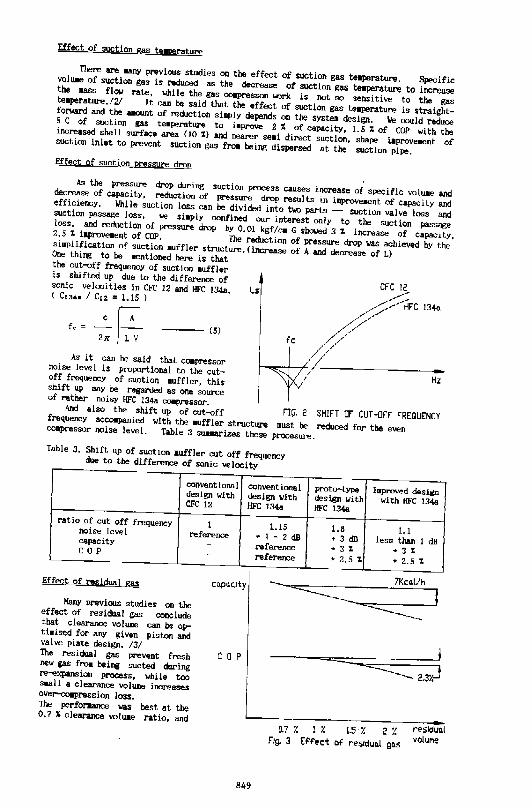
As the pressure drop during suction process causes increase of specific vol uae and decreASe of capacity, reduction of pressure drop results in iDJproveaent of capacity and efficiency. While suction loss can be divided into two parts - suction valve loss and suction passage loss, ""' si•ply confined our interest only to the suction _passage loss, and reduction of pressure drop by 0.01 kgf/c• G shoo.led 3 % increase of capacity, 2.5 1 i11prove1ent of COP. The reduction of pressure drop was achieved by the si11plification of suction •uffler structure. (increase of A and decrease of L) One thing to he aentioned here is that the cut-off frequency of suction auffler is shifted up due to the difference of sonic velocities in CFC 12 and HFC 1348. < c., •• 1 c,2 = 1.15 l
fo = _c jA 21l j-;; (5)
13-4o.
fc
~~-4~~~----------------------Hz
As it can he said that c011pressor noise level is proportional to the cutoff frequency of suction •uffler, this shift up may be regarded as one source of rather noisy HFC 134a coapressor. And also the shift up of cut-off FIG, 2 SHIFT OF CUT -OFF FREQUENCY frequency accoapanied with the •~ffler structure IIUSt be reduced for the even CQIIpressor nolse level. Table 3 suuarizes these procesl.ll'>!. Table 3. Shift up of suction 1uffler cut off frequency due to the difference of sonic velocity
conventional conventional design with design with CFC 12 HFC 1344
ratio of cut off frequency 1 1.15 noise level reference •1-2dB capacity - reference c 0 p - reference
Effect of residual gas co.p~oty
Many previous studies on the effect of residual gas conclude that clero-ance volume can be optbised for anY given piston and valve plate design. /3/
c 0 p
proto-type I11proved design design with wl th IIFC !34a HfC 134&
1.8 1.1 • 3 dB less than !dB • 3 1 • 3 1 • 2.5% • 2.5 %
The residual gas prevent fresh new gas frOII hei~ sucted during re-e>q>ansion process, while too sull a c I earance volume increases ov~pression loss. The perfonlal!Ce was best at the o. 7 1 clearance voluae ratio, and L-~. r!'Siciuo.l 0.7 i. 1 % LS i. 2 %
voluf'le
849
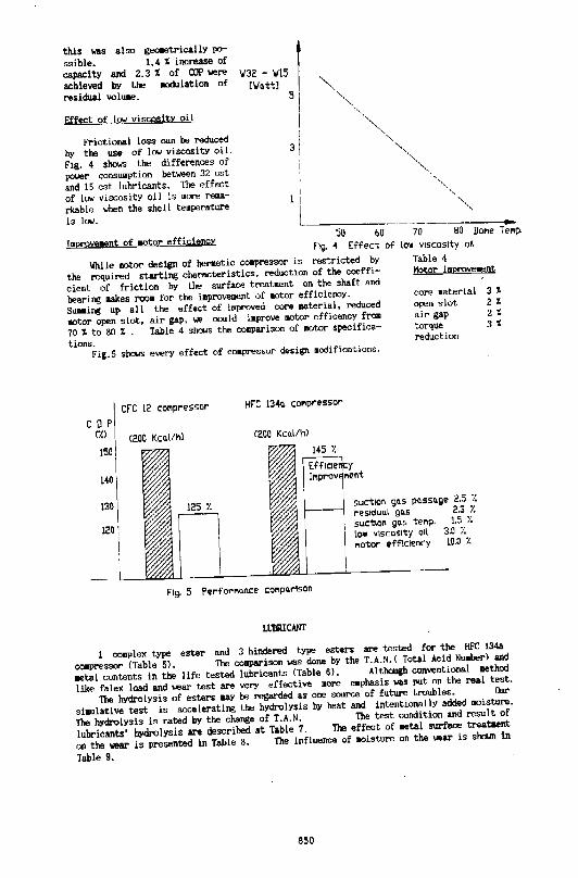
this was also g...:.etrically po
ssible. 1.4 l increase of
capacity and 2.3 l of COP""'"' achieved by the aodulation of
residual voluae.
Effect of lgw viscosib oi I
Frictional loss can be reduced
by the use of )(OJ viscosity oi I.
fig. 4 shows the differences of
power conSUIIption between 32 est
and 15 est lubricants. The effect
of low viscosity oil is 110"' re~~a
rkable when the she II te11perature
is !(OJ. -l11prcve~~ent of motor efficiencY
so 60 70 80 DoMe T el'lp.
fig. 4 Effect
'llhile motor design of herlletic c011pressor is restricted by
the required starting characteristics, reductlon of the coeffi
cient of friction by the surface treat~~ent on the shaft and
bearing !lakes roo11 for the imprcveoont of 110tor efficiency.
SWilling up a II the effect of iDiproved core 11ateria ), reduced
aotor open slot, air gap, ""' could iaprcve 110tor efficency from
70 l to 80 t . Table 4 shotJS the ccmparison of •otor specifica
tions. Fig. 5 shows every effect of compressor design 11odiflcations.
c 0 p ('l.)
150
140
CFC 12 co,.,pressor HFC 1'34o. COI'Ipressor
<200 Kco.l/h)
Of lOW VISCOSity Oil
Table 4 Motor imprcv...,.nt
core material 3 t open slot 2 t air gap 2 t torque 3 t reduction
130 suction go.s po.sso.ge 2.5 'l.
re siduo.l go.s 2.3 Y.
120 1 suction gc.s tel'lp. 1.5 1. low vtsc:ostty otl 3.0 7. 1'\0tor efficiency 10.0 /..
Fig. 5 Perforl'lo.nce col'lpc.rtson
LIJIIRICANT
1 c011plex type ester and 3 hindered type esters are tested for the HFC 134a
ccwpressor (Table 5). The cooparison was done by the T. A. N. ( Total Acid NuaberJ and
aetal contents in the life tested lubricants (Table 6). Although conventional method
like falex load and ""'ar test are very effective 110re eaphasis was put on the real test.
The hYdrolysis of esters uy be regarded as one source of future troubles. Our
slaulatlve test is =lerating the hydrolysis by heat and intentionally added 110isture.
The hydrolysis is rated by the change of T.A.N. The test condition snd result of
lubricants' hydrolysis are described at Table 7. The effect of aetal surface treataent
on the ""'ar is presented in Table 8. The influence of llDisture on the ~o~ear is sb(Ooln in
Table 9.
850
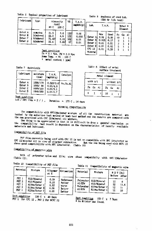
Table 5 Typical properties of lubricant Table 6 Analysis of used Lub. (500 Hr life test ) Lubricant Type viscosity VI T.A.N.
(est) (,.gWH/g) Lub. T.A.N. Metal * 40 c 100 c Element Ester A Ester B Ester C Ester D
COiplex 31.5 5.8 133 hindered 22.5 4.6 132 hindered :l!.49 5.22 102 hindered 32.4 5.25 97
Test !<Ondjtion Ps " 0.1 Mpa, Pd "3.0 Mpa Do1e Teqp. = 95 - 105 C * ootal content [ PPIIl
Table 7 Hydrolysis
Lubricant .aisture T.A.N • Catalyst (ppq) (llgl{OH/g)
Ester A 1000/170 0.025/3.6 Fe,C11,Al Ester B 1000/ 90 0.01/4.8 Ester C 1000/150 0.01/3.1 Ester D 1000/260 0.01/2.7
Test condition
0.01 0.025 0.01 0.01
Lub I llFC 134a " 3 I 1 Duration = 175 C , 14 days
New Used Fe Cu Ester A 0.01 0.26 10 EsterB 0.025 0.17 3 Ester C 0.01 0.01 5 Ester D 0.01 0.02 5 CFC 12 0.01 0.30 5 Mineral
Table 8 Effect of lletal surface treatment
Metal ele~~ent
with s/t without s/t
Fe Cu AI Fe Cu AI
5 1 1 10 1 1
I I 1 l I
MATI'RIAL COMPATIBILI"l1'
AI 1 I I 1 1
The COipatibility with HFCI34a/ester 1ixture of all the construction eterial are tested by the autoclave test qethod or bOib test 1ethod and the reSillts are c01pared with the one practiced with CFC 12/lineral oil 11ixture. One thing to be appreciated is that it is difficult to draw a general conclusion as the c011patibility test result is dependent on the characteristics of locally available ll!lterials and lubricant.
COilpatibi lity of PEl' fl11
PET filll currently being used with CFC 12 is not so cOilpatible with HFC 134a/ester as CFC 12/lineral oll in view of oligoer el(t;raction. But the one being used with HCFC 22 sh<M> good C<WP~~tibility with HFC 134a/ester. (Table 10) • CO!IJ)8.tib\l ity of 1118g1!etic wire
Both of pcjyester nylon and EI/AI wii'O shows COIPStibllty with HFC 134a/ester (Table 11).
Table 10 C01patibi!ity of PEr fill Table 11 C01patlbility of llllgnetic wlre Material Mixture Olig.-r Estlation Material Mixtlll'e B D V [Kv] wtX
Before After PET 1 RI2/Mineral 0.28 RefereiiCe Polyester R12/Mineral 12 6 PET 2 R12/Mineral 0.10 Better AIIEIW R12/Mineral 12 11.6 PEr l R134a/Ester C 0.53 lilorse Polyester R134a/Ester C 12 11 PEr 2 R134a/Ester B o.os Better Al/EIIil R134a/Ester C 12 10 PET 2 Rl34a/Ester c 0.03 Better
Test condition 130 C x 40 Days Test condition 150 C x 7 Days PET 1 for CFC 12 , PET 2 for HCFC 22 ~ No Blister was found.
851
COOCLUSION
(1) HFC l34a can be used instead of CFC 12 in the current refrigeration systea.
coapressor design IIOdification is needed for the sake of energy efficiency.
of 20 '1: iaproveaent of COP was achieved in this study.
( 2) Lubricant
But the Total
Hindered type ester shows better characteristics of lubricant than c011plex type ester.
But a great aaount of attention •ust he paid to the prevention of 110isture penetration
Oess than 40 ppa) during compressor manufacture process as there still re~~ains
the possibility of hydrolysis.
(3) Mftterial C011patibility Both of polyester nylon and El/AI 11lre can be used 11ith HFC 134a/ester 11hile it is
necessary to revie11 the co11patlbility of PET filll in vie>~ of oligomer extraction.
ACKNOLEDGEHOO
The authors 11ish to thank Director Tadanori Kato of Japan sun oi 1 co. and Manager
Lee, jong man of lsu che•ical co. for their contributions to this 1o10rk through many
experiaents and discussions.
(1) J. Kill &Jid Ill. Soedel, "Perforaance and gas pulsations when puaping different gases
with the s1111e co11pressor. ", 1988 Purdue COilpressor engineering conference.
(2) Hideki Kawai, " The developaent of high efficiency co•pressors by reducif€ suction
gas te•perature, ", 1982 Purdue c011pressor engineering conference.
(3) John J. Jacobs, " Analytic and experi•ental techniques for evaluating compressor
performance losses.", 1976 Purdue cc11pressor engineering conference.
852
GBNBRAL STABILITY AND DESIGN SPECIFICATION OF THE BACK-PRESSURE SUPPORTED A.XIAU. Y COMPLIANT ORBITING SCROLL
James W. Bush Prugma Manager
David K. Haller Project Leader
Scroll Compressor Design Uoirm Tcclmologics Curter Syracuse, New York 13221
ABSTRACT
CbrisuJpbl:r R. Galante Project Engineer
A linear, first order relationship ~nay be used to approximate the stability chararu:ristk of the back-pressure supported oriming scroll. Tbe r=sulting average tip loads may be similarly reprcseorm. Openning .woes of incipieDt orbiting scroll iDstability ru-e found to :qJProximately follow woes of COIISWlt compression ratio. A simple design procedlU'e is presented wbicb may be used to specify iWal compliaDce Jlll1!llfliCn for Sllbility over an ubitmy opemiDg I'lllge and to estimate resulting tip loads.
INTRODUCI10N
Tbe scroll compressor collllllOIII.y coosisls of one scroll Olbiting witb respect to a second, typically fixed, scroll. Hence tbe tmns "orbit:iDg scroll" and "fixed scroll". These scrolls eacb bave a flat floor portion on wbicb is an involute-sbaped wrap. As the seroUs intermcsb, a series of tnpped pockets ru-e formed wbicb decrase in size as tbey travel toMnls tbe CCDta", compnssing the gas witbin. Ideally the tips aad flanks of the wraps would always be in light COiltJcl for ttuly sealed pocbts.
DuriDg compnl5Sion, gas ~ acts against the seroUs to separate diem bodl axially 1111 tadillly. These fortes IIIWit be countetcd by some mechanism or sttucture. In so-called compliant dcsigos, the :;crolls are brought imo positive CODtll:t to properly seal pockets for dlicieDt COIII[Jn:5Sioo. 1be seroUs are bekl in piJr.:e by extcma1 forces, USUIIIy gas-induced, wbicb allow tbe scrolls to "float • and *tcrmine dleir OWII geometric relal:ion to eiCil ocbet. Tbis ooruigid support also allows the seroUs to sepiRte in response to Uquids or small debris which may be ingellled.
CompliaDI:e in the radial difectioo is usuatly provided by mo:baoical meus in the orbiting scroll drive. In tbis piper we focus on compliaDce in tbe uia1 diredioa 1111 discuss the theory and design coosidmtioas for stable oper'ltion over ID arbittary I'lllge of conditions.
FORCES .ON 11IE SCROLLS
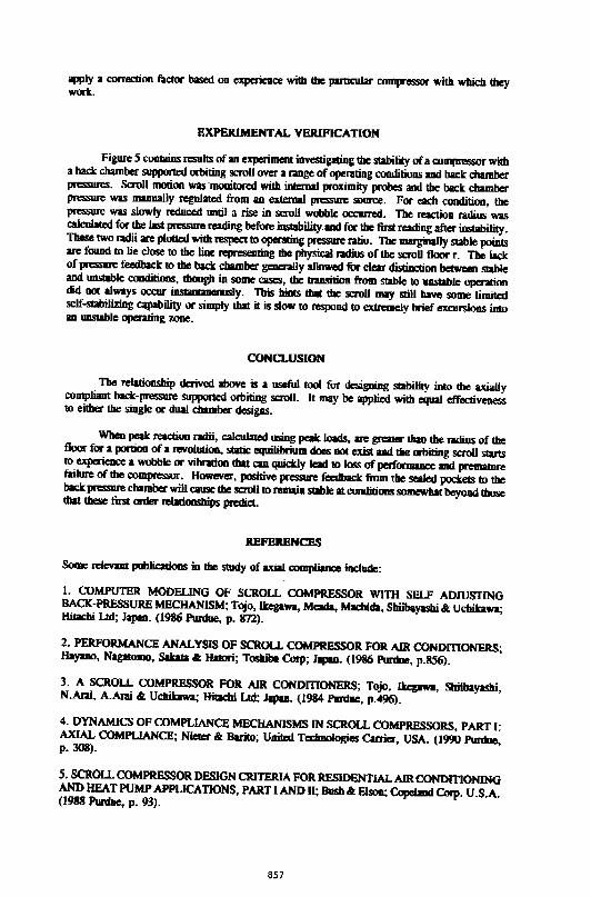
1be forces on the orbiting scroll resulting from the compression process are shown in Figure 1. The: radial p:; force, Frg, KtS along the tine between the centers of the two scrolls and tties to pusb tbem apart to a common center. 1be ~~~~~ gas force, Ftg, acts at the midpoint of and peqJCDdicular to die line betwcal the ccmers of the twO scrolls. This is the fon.:e against wbicb die ac:tua1 wort of compression is performed. Tbe axial gas force, Fag, KtS midway along tbe line between the two scrolls IDd IIOl'llll1 to the plane of orbitin& IIIOiioD. This fon:e tmds to sepanre the scrvlls uially. All fon:cs act equally and S}'IIIIIICiricay 011 bod! scrolls.
For axial compliance design, we must, as a begjlming, ovcn:ome tbe influence of the axial gas force. For the back-pressure suppm1cd orbiting scroD, gas pressure from tbe scaled
853
~ cbambcrli is ~ to sealed 1DIICS on the back of the orbiting scroll. The
raultmg fon:e overcomes the axial sepm;din! foo:e Ifill J111S11es the orbiting scroll into COR1act
with the fued scroll. In addition to Ibis, it is ~ to add an additiooal force increment to
oven:ome a clEacteristic overtw:ning lllOIDCIIl wbic:b ICts on the orbiting scroll.
In Figure 2 is a diagJalll of the fOI'CCS acting on the orbiting scroll in the plane wbicb is
puallel to the axial and Wlgemial gu forces. For tbis analysis, there is abo an influence from
the radial ps force, but it is very small and will be neglected for this lim-order approximation.
In addition tD the gas forces, there is a force applied to the drive bearing of the orbiting scroll
in response to the tangential gas force IIHI a reaction force acting axi.ally between the orbiting
md fixed seroUs. Force summations in the axial and tmgential directions are:
(1)
(2)
wbere tFa is the axial force summation, Fbc is the net back chamber force, Fr is tbe scroll-to
scroll axial reactioo force, and fb is the scroll drive bearing foo:c.
Since the tmgential gas force and bearing rc.:tion do IIOl typically act on a single line, there is
also 1111 overturning DIORlCDl ~ with tbcul:
tM=O=Fc,l-F:ri (3)
wberc 1 is the dislance between the midpoint of the scroll vane and the drive bearing (the distanCe
beh!lecn Frg md fb ). Tbc value of the rcactioa radius, r, will vary aecording to the puticular
back-chamber design and operating condition.
OltBmNO SCROLL STABILITY
If the tbaJrctical wluc of the I'CICiion radius sbould exceed the pbysieal size of the
orbiting or fixed scroll, wbicbcvcr is smaller, it ...W in fact be confiDed to tbe pbysieal edge of
the 'JJI11· Since a sutfidcnt radius tD balanl;:c the moment eqution is uavaiWJ!e, the moment
SWIIIIIatioD will no lon!cr be zero, the orbiti:D! scroll will no longer be in Sialic equilibrium, mel
it will stut to ovcnum UDtil it comes into contact with some other RICCbanieal n:straint. This
action, coupled with the orlrital movement of the scroll, results in a sort of wobbling RIOiion with
aU the axial COIIIaCt occurring along the edge of the pan.
This wobbling, or iDslability, results in leakage through the gap opeDed by the seplnltal
tips, edge loadiog of the scroll sur1'31:ts, and angular misaHgmnent of the scroll drive bearing.
All these em quickly lead to loss of pcrformancc IIHI pn:lllaiiUe failure of the C01IIJRSSOI".
GAS FORCE EQUATIONS
The uialllld tiDgaJtial forces, wbctber cxpniSScd in peak. or average tt:rms, consist of
nvo coiiiiXJRI:IIIll. Part of eacb force is derived from the ]II"C5SIJI'e in the sealed poctcts, wbidi
is a rw.:tioD of scroll &eometry and SUCiiOD pra.mre only. Tbe OCher part is derived ftom tile
JlRiSSIR in the discharge pocket and is a ftmction of scroll pometry and the suction to disclllrge
pressoR diffcn:Dcc only. 'l'bc:!c forces em be written in tbe linear fonu:
854
(4)
(5)
where Ps and Pd are the COmpre5501" suction and discharge pre5SUfeS respectively. The Conslants C I through C4 are functions of the paniwlar scroll geoOJCtty. Tbese force cqualions arc derived to be ·gage" forces, i.e, t"CSUltiltg from pressures above the "ambient• pressure Ps. The constmts Cl through C4 may be derived to represent either avenge or peak forces. The timing of the peak force, wbether uial or tangential, is dependeDt on wbether the compressor is openting above or below the design pressuRi ntio. The peak force occurs just before the discharge porting point for operation below the design pressure ratio aDd just after porting for operation above the design pressure ntio. For this fCISOD, the value of the four coostaDt coeffic:ients for peak loads will be different for the two zoaes of operation.
Bad:: chamber pressure is typiaUy provided by a combimtioo of pressure from tbe di~ and from the scaled rompression pockels. In this lllllllll!if, the back chambc:r force may be made up of two compooems Vibidl bebave in a similar IIWIIICI", with respec:t to operating pressures, as do the inlerml gu fon::es. A c::ommoo IDCibod is to provide two ~ dlambers for tbese force eompooems. In tbat QISC, tbe b.:k chamber force may be written as
(6)
where Co tcpteSCDts tbe time--average normalized pressure seen by a vent communic:ating between an intermedim: pressure baclt c:bamber and a scaled c:ompressioa pocket and Ai and Ad respectively are the areas of the intermediate aDd discharge back c:bambers. This metbod is most commooly applied in the bigb-side compliant «biting scroll design aDd in the eompliant fixed scroD design, in both of wbicb it is c:onvenialt to provide discharge pressure at the caner of the axially compliant scroD.
AnodJer medlod cspecialiy suited to the m.o side eompliant orbiting scroll design is to use a single back c:batnber whose vent is exposed to iiW:rmediate pressure for a portioo of the time and to discharge pressure for the remainder. Figun: 3 illustrates bow suc:b a vent bole sees tbe eompressioa J:ll"lll:li55. In tbis eumplc Pd t.ppeu to be equal to the pressure in the sc:alcd poc:kcls as they open to discharge, but 1111y vary indepmdmtly. 1be vent is loc:ated at an angle v from the inner end of the Map. In ooe revolution (or orbit) the vmt sees the pressure in tbe scaled poc:bt for a period of v/2 ... , and it sees Pd for a period of (2T-v)t2.... The av~m~ge pressure seen in the sc:alcd poc:kecs is c:alculatcd by ISSUming a polytropic: c:ompressioa proc:e5$ md solving m averaging inlegral wbicb will result in the form Co Ps, wba-e, similar to the two c:bambcr design, Co is I funl:lioo of the scroll pmcGy and DOW V. The badr; c:bamber pressure cqualioa em be wriUal as:
(7)
where Pbc is the aveage back c:bambcr pressure. Narc tbat tbis equation is of the same linear form as the bat.:k c:bamber force cquarion for the two dlambcr ease. The back dlambcr force is found by simply mulliplying the pressure by the c:bamber :aa:
(8)
855
STABILITY EQUATIONS
Rc:an'lllgiog lhe forte and momem SUIIIIIIIlion equations lbove to solve for r gives
Submtw:ing dle force equations for Ftg, Fag, and Fbc gives:
I"' l<C,P,+C,Pdl
[ v ( 2n-v Abc
211: C0 -1) P.,+~ (P,.-.Psl ]-C3 P8 -C•Pd
Simplifying aod grouping terms fur Ps and Pd results in:
[lc,_] P.+ [lC,] Pd r~--------~~~~~~~-----
[Abc( 2v C0-1)-C3 ] P.,+ [Abc 2n-v -C
0]P,.
11: 211:
Lettmg Kl, K2, K3, and K4 represeat tbe above bracketed terms, respectively, and dividing the numerafDI' and denominator boUt by Ps, we bave:
r= K,_ +JC,OPR ~+K00PR
(1)
(2)
(3)
(4)
w~ OPR is the operating pressure mio of the compressor. Tile reaction radius r is found to be c:omunt fur a given openling pressure l'llio of tbe compressor.
A similar derivation and simplification for tbe "tip" or re.ctioo force Fr gives:
Fr•P,(K)+K0 0PR) (5)
DESIGN PROCEDURE
lines of cons1mt reaction radius are superimpoSed on an oprnting envelope in Figure
4. 111ey correspood to co~~SADt operating pressure rmo lilies. Tile design procedure is to cJJono;e
two extreme design points in tbe operating envelope, for eumple. die maximum and minimum expected operating pressure ratio points, and fix r equal to the radius of lbe OJbi1ing scroD floor portion. Tbi5 re5Uits in two linear equations wbich are solved simu1WICOU5ly for the two UllblowPs of Abc aod v. As a RSllt, all other r values widJin the operating cavelope will be less thaD tbe radius of the floor. Tbi5 ISSUJ"CS slability over tbe entire envelope. The final values of Abe and v must be chosen within the physical limits of the scroU COIIIJiftSSOI''S layout.
I:n pncticc, usc of peak IOids will result in a very cOIISCI'Yltive design with higher lip loldiD! than may be really required. WileD lbe COIIIpRiSSlll" reaclles an UIISilble opemiDg eoodition, based Oil peak 1o.t calculatioa, it will begin 10 wobble for • small portion of tbe cycle while the peak loads exist. The resulting lip leakage causes higher pocket pressures whic:b in tum feed back 10 the back chamber, nising ils pressure as weU. Tbi5 positive feedbKk will hold the scroD in a quasi-slable condition beyoad the expecral !Uble operating nD!C- on the otber
hand, usc of average loads ooly willlibly be iamfliciall to assure srability. Designers should
856
apply a correction factor based on ~ce with the particular compressor with wbicb they wort.
EXPERIMENTAL VERIFICATION
Figure 5 contains results of an experiment investipting the stability of a codl(llel50r witb a back chamber supported orbiting scroll over a range of operating conditions and back chamber PfCSSIIlCS. Scroll motion was 'monitored witb intema1 proximity probes and tbe back chamber pressure was manually regulated from an external pressure source. For each condition, the ~ was slowly l"Cduc:ed until a rise in scroll wobble occurred. Tbe reaction radiw; was calculated for tbe last pressure reading before inst!bility.md for the first reading after instability. These two radii are plotted with respect to operating~ ratio. The marginally stable points are found to lie close to the line representing tbe physical radiw; of the scroll floor r. The bet of pressure feedback to the back cbamber generally allowed for clear distiDction between stable and un.stmle conditions, tbougll in some cases, the transition from stable to umuble operation did oot always occur i.nstllnwleously. Tb1s bints tbU the scroll may still bave some limited self-stabilizing capability or simply that it is sl0111 to respond to extremely brief excunions imo an UOSWIIe operating woe.
CONCLUSION
The relationship derived above is a useful tool for designing stability into the axially compliant back-pressure supported orbiting scroll. It may be applied witb equal effectiveness to either the single or dual cbamber desigas.
Wbeu peak reaction radii, calculated using pelk loads, are greater than tbe ndiw; of the floor for 1 portioD of a revolutioD, static equilibrium does not exist and the orbiting scroll stuts to experieuce a wobble or vibration that can quiclr;;ly lead to loss of perfOI'JDIIlCe and premalUre flilure of the COIIIpl'tSSOI". However, positive pressure feedback from the sealed pockets to the back pressure chamber will cause the scroll to remain stable at conditions somewhat beyood tbose tbal tbese fim order relationsllips predict.
REFBRBNCES
SoJDe relevmt publications in the study of uial compliaqce include:
I. COMPUTER MODEUNG OF SCROLL COMPRESSOR WITH SELF ADJUSTING BACK-PRESSURE MECHANISM; Tojo, Ikegawa, Mcada, Machida, Sbiibayasbi & Uchikawa; Hitachi Ltd; Japm. (1986 Purdue, p. 872).
2. PERFORMANCE ANALYSIS OF SCROLL COMPRESSOR FOR AIR CONDmONERS; Hayano, NagafmDO, Sabia .t Halori; Toshiba Corp; Japm. (1986 Purdue, p.856).
3. A SCROLL COMPRESSOR FOR AIR CONDmONERS; TQjo. Ikepwa, Sbiibayashi, N.Ani, A.Anli & Uchibwa; Hitachi Lrd; Japm. (1984 Purdue, p.496).
4. DYNAMICS OF COMPLIANCE MECHANISMS IN SCROLL COMPRESSORS, PART 1: AXIAL COMPLIANCE; Niefcr & Buito; U!Wd Tcdmologies Carrier, USA. (1990 Pllnlue, p. 308).
5. SCROLL COMPRESSOR DESIGN CRITERIA FOR RESIDENTIAL AIR CONDITIONING AND HEAT PUMP APPUCATIONS, PART I AND II; Bush & EJsoa; Copclmd Corp. U.S.A. (1988 Purdue, p. 93).
857
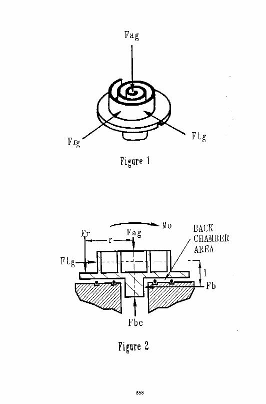
Fag
Frg
Figure 1
Er ..- ........_ Mo
Fag a-- r ___,_.
Fbc
Figure 2
858
Ftg
BACK CHAMBEE AHEA
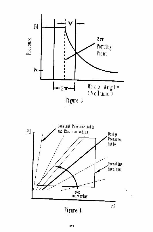
Pd
Figure 3
Wrap Angle (Volume )
Constant Pressure Ratio and Reaction Radius
Figure ~
859
Operating Envelope
Ps
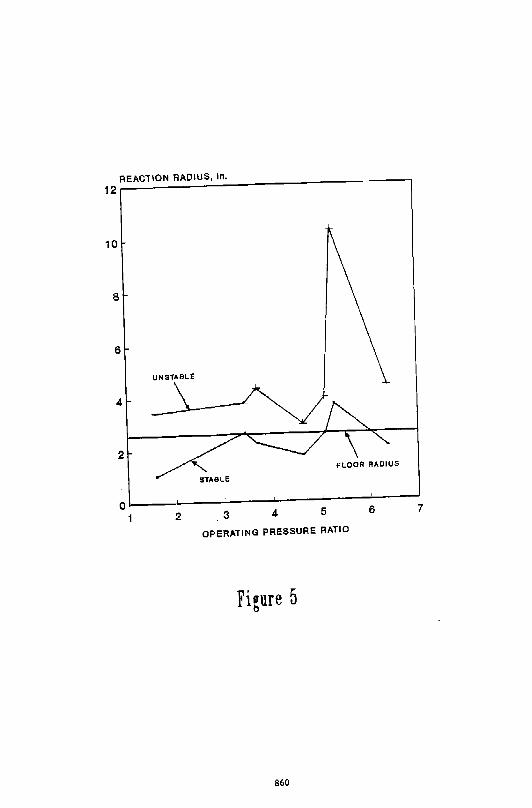
REACTION RADIUS, ln.
12r-----------------------------------.
10
8
6
UNSTABLE
4
2
STolBLE
0~----~----~----~----~----~----~
1 2 .3 4 5 6 7
OPERATING PRESSURE RATIO
Figure 5
860
DYNAMICS OF AN ORBITING SCROLL WITH AXIAL COMPLIANCE PART I- SIMUI,ATION OF ORAfTEil AXIAL MOTION
H.T. Shu and A-A. Pera.cchio United Technologieo Re•earch Center
Silver Lane · M.S. I 9 East Hartford, CT 061 OR
ABSTRACT A dynamic model was developed for investigating the axial motion ,,fan orbiting scroll design which incorporates passive axial and radial compliance m•chanisms. Th~ rnnd~l uses three degrees of freedom to describe the orbiting scroll axial motion. It also in-cludes rnnt>ct constraints for the thrust surface, the wrap tip and flanks, the crank case, and the hub bearing. The equations of motion were derived using the Lagrangian formulation. The-sy•tem natural froquencies wore predicted, and forced reoponse analyses were performed. Results of the orbiting scroll dynamks analysi, nnt <•IllY shnw good agreement with the experimental data., but abo highlight the importance of the c<>n<traiut.s.
1. INTRODUCTION A comprehen•ive re•~arch program has b~en undertaken hy th~ !lnited Technologies Reoea.rch Center (UTRC) to develop improved understanding of scroll cnmpressor perfnrmance and dynamics in support of Carrier's product applications. This research program consists <>f not. <>nl_v extensive analyticallnodeling but afso experimental investiga.tJOn or System perfnrmanc-e, prPSSUTE"5 1 tE'mpera.tures, vibrations, and dynamic characteristics using instrumented compreosors (Ref. l ). In this paper, a simulation of the orbiting scroll axial motion Is presented.
Setrf;'raJ investigations of scroll compressor dynami(' lu•havinr involving orbiter motion ha.ve been re~ ported (Refs. 2 to 4). Thse studies (which usually include an orhiter, "n Oldham coupling ring, an axial and radial compliance mechanism, and a crank shaft) have been <1<-velnped using D'Alembert's principle to model the orbiter inertial effects. These studies assumed that l.he <>rbiter motion wa.s constrainted to be in a. plane perpendicular to the shaft centerline and within I hat plane, l.o execute a circular orbiting motion. Some have allowed for variations in shaft speed (Ref.3). The effect of damping and stiffness of the .backchamber seal mechanism on the axial motion were not mnsidered These studies have served ao first generation •croll compressor design tools. However, in ord"r to furth~r improve understanding of compression effi.Ci@ncy, COmpOnent reliability a!'ld (Otnf'fE"SSI"Jr noisC' 1 thr:- ci~V('JopntE!nt of a more sophisticated dynamk model is requirE>d ~o account for additional degre@!i of frPE"dom of motion a"d backchamber seal effects.
2. DYNAMIC MOI)F,J,JNG 'rhe dynamic model developed for investigating th~ snnll <>rbitN axial motion is described in this section. The model consi•ls of three degrees of freednm r•presPnt•d by three generali•ed coordinates. It also account• for motion conotra.ints that might occur duet<> wrap tip rnnt"-d with the mating baseplate, wrap Hank conta.d with that of the fixod scroll at othN than I h• ideal cnnta.ct line, the thrust surface contact, motion constrained by the mechanical limits of th~ (-omprE>ssinn (tf th@ backchamber seals. and finally, contact of the orbiter hub "'ith the drive ohaft mechanism.
2.1 Equations of Motion
The ochematic diagram of an orbHing scroll model is shown in Pig. 1, where F., M~, and Mv repreoent the a.xial component of the time va.rying loa.d and the x a.nd y \omrwncnts of the time varying moments acting on the orbiter during comperosor operations. (Further descriptions <>f theoe three parameters will be given in the Case-Study Section.) The orbit~r is supported hy twu '-" three backchamber seals with rad..ij rt 7 r2 , and 1"'J respecthrely.
Let I) (X,, Yj, Z 1 ) be the inertial coordinat• system with origin 0 f fi:<~d a.t the shaft center, 2) (=<, y, z) be the moving coordinate syotem with origin 0. fix~d a.t tb~ renter nf the baoepla.te bottom surface uf orbiting scroll and alwa.yo parallel to the inertial coordina.t~ system throughout the entire compres•or operation, 3) (r., n) be the radiuo of orbiting circle and shaft sp~~d, and 4) ( z0 , 0.,, Or) be the generalized coordinates deocribing the orbiter axial tra.nolation and rotations of -,: and y axes. If z0 , (J~, and (J¥ are small, the dioplacement and velocity vectors of a small element of the orbiter at poi11t P(:t,y,z) can be
861
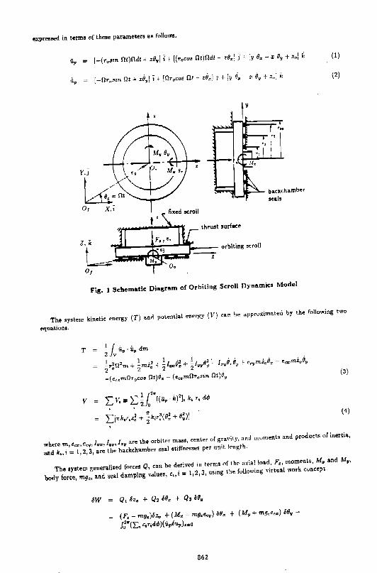
expreooed in termo of theoe parameten a• follows.
(1)
(2)
Or
thruet •urft.ce
Fis. 1 Schematic Dia1ram of Orbiting Scroll Dynamic:• Model
The system kinetic energy (T) and potential energy (I') can he approximated by the following two
equations.
T l r . . 2 lv "•. ilp dm
~r;n2 m. + ~mi~ + 2/~rrO! + ~111,9~ I~yBTiJY +- c~"ym.i"O:- ec~mZQOY
-(<«m!1r0 w• !1t)O,- (e .. m!1r0 •in !lt)li, (3)
(4)
where m., ec:z- 1 e~;y 1 l!J!!!!' !""' l:~:v a.r~ the orbiter mass! [email protected] of gravily. fH\d moments and products of inertia,
and k.,i = 1,2,3, are the backcha.mber sea.l stiffM•••• p~r unit. knp;th.
The system generalized forces Q, ca.n be deriv~d in tNms nf 1h~ axial load, F, moments, M, a.nd M.,
body force, mg0 , and seal d;:t.mping nlues, c.,i"' 1,2,3, using the following virtual work concept.
(F,- mg0 )oz. + (M.- mg.e._) o6, + (M, + mfl••=) o6• -
J.J .. (E, c,r;d,P)(ilpou,.) ... o
862
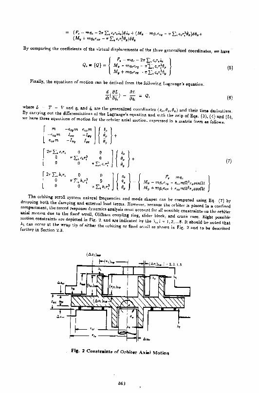
(F,- mg.- 2" 2:, c,r,z.)oz. + (M,- mg.<0 y - "2:, c,r;iJ,)60,+ ( M• + mg.e._ - 11" L., c,r~0.)60y
By comparing the coeffieiento of the virtual diopla.cemento of th~ ,three g~neralized coordinates, we have .
(5)
Finally, the equations of motion can be derived fr<">ln the following Lagrange's equation.
d 8L 8[ di(aq,l - a;;; = Q. (6}
where L == T - V and q, and q, are the generalized coordinates (z.,o.,o.) and their time derivatives. By carrying out the differentiations of the Lagrange'• equation and With th~ help of Eqo. (3}, (4) and (5), we ha.ve three equations of motion for the orbiter axi=tl motion 1 cxprei;G('d in a. ma.trix form a.s follow a.
[ -e:m -ecym ~~m J { Zo } ~ I •• !•• ii.,
e .. m -!"" lw 8.
[ 21r~,c,r, 0
"L,~ c,r; ] {
•• } +
,. L,, c,r~ o. (7) 0 o.
[ 211" L.t•· 0
1rl:,~k,r? ]{
z.
} { P, mg.
} 1rL.,Ic,r? o. .!Hr ~ 1n.qcp_t1!1 - ec.zm0 2T 0 3in0t
0 o. Afy + mgr.ecT + ec.:~:mf1: 2 t0 CO.!flt The orbiting scroll system natural frequencies and Inode shapes can be computed using Eq. (7) by dropping both the damping and external load terms. However, beraus• the orbiter is placed in a confined compa.rhn.ent, the forced respon!e dyna.mic::s a.nalysis must acconnt for all poMible constraints on the orbiter aria! motion due to the fixed o<.roll, Oldham coupling ring, slider block, ar1d crank case. Eight possible motion constraints are depicted in Fig. 2, and are indicated by the ,\., i ~ 1, 2, ... 8. lt should be noted lhat >., can occur at the wrap tip of •it her the orbiting nr fixed s<rnll as shown in Fig. 2 and to be described further in Section 2.3.
Fie. 2 Constraints o( Orbiter Axial Motion
863
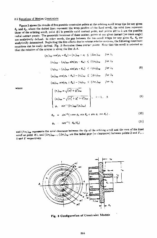
2.2 Equations of Motion Con•traints
Figure 3 show• the deta.ils of five poesible con•traint points at the orbiting scroll wrap tips for a.ny given
8: and IJu, where the dotted lines represent the wrap profiles of the fixpd srroll, the solid lines repr~sent
those of the orbiting scroll, point #1 is possible a:<ia.l contact point, a.nd pnints #2 to 5 are the possible
ra.dla.l contact point•. The geometric locations of these contact points at a.ny given instant (or cra.nk angle)
are a.na.lytically defined. In other words, the gap between the two scroll wraps for any given IJ:, (J• are
analytically d~termined. N~glecting the film effects due to orb1ter rei• rive motions, the following constr .. int
equations can bt' ea.oily derived. Fig. 3 illustrates these contact points NntP lha.t the scroll is oriented so
that the rotation of the orbiter is along the line A· A.
where
(p1 )<op co•( 'l't - 8,.) - ( z, )<or - zo :; ( t:.z,),,r for .X,
(r2).,,- (p2).,, Ji7t('1'2 - 8,.) $ (t:.r,).,, fnr .X,
(r,) .. ,- (p,) .. , Ji7t('l'3- e.,) < (6r3),,p fnr .X3
(P<)hp •zn('l'• + 8,.)- (r<)top $ (t:.r,),.r for -'•
(p,)e,p ;in(<po + 0,.)- (r5),., s ( t:.r,),.p Jnr .\5
l (r,),.. == ,j(z~ + Y?le.r )
(p,),,p- j(x~ + Y? 1- z:J.,r •
<p, ~ ;in-'((r,),.p/(-p,).,p)
i"' l, .. , 5
(8)
(9)
(10)
(11)
and (6zt),.p represent. the axial clearance between the tip of the orbiting s<roll and the root of the fixed
scroll at point #1, a.nd (6r2),.,, ..• , (t:.r5 ),., are the radial gaps (or clearanre•) between points 2 and 2', ... ,
5 a.nd 5' respectively.
Fir;. 3 Conflr;ur11.tion of Constr10int Models
864
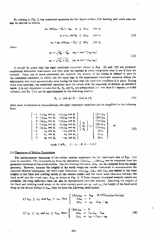
By r<>fering to Fig. 2, the constraint equatiomo for the thrust surfa.<"r, huh bearing, and crank case can
also be derived ao follows.
where
for .\r
for~"
p.,"' Jzl, + rl,., "'''"' •in"" 1(r.,./p.,)
P!K"' Jzf., + ~~. 'P~K"' .,n·· 1(r0,jp,,)
(12)
{13)
It should be noted that the oight mnstraint equations shown in Eqs. (8) and (12) are nonlinear
conditional holonomic constraints, and they must be checked at every int~gration step to see if they are
violated. Once one or more constraints are violated, the m"tion nf the orbiter io defined in part by
the conotr,.int condition, in which case the equal sign in th~ appropriate mnstraint equation defines the
relationship that must geometrically exist during the time that the <onstra.ini condition is in place. During
those time intervals, the constraint equation• must b(' oolved with th"' equation• of motion, as described
belo ... It io also important to note that 9., 9y, and 9., are a.lwa.yo small (i.•. le"" than 0.1 degrees, or 0.002
radiano), and Eq. (11) ca.u be approximated by the following relation.
{14)
After some mathematical manipulations, the eight constraint equations can be simplified to the following
fonn.
-1 (rl).,. 01n ¢, -( rt),,. cos ¢. {6z,).,0
0 (•2) ... .!tn ¢, -(z2).,. cos ¢. (6r2)hp 0 (zJ)hr sm ¢. -(z,)tor cos ¢0
{ } (6r1 ).,.
0 (z,),,, sin¢, -(z4).,. cos ¢. •• {6r1 ) ...
0 (••)tor •in ¢< -( zs) ... cos ¢. e. s (6rs).,0
-1 ru "in t:P~ -rh ca.!l'¢c: o. ~z;.
or (15)
T~;c .!in ¢c -Tc.:: Co" !'Pc .6.zr.~
0 Zfn- .!ltn t/Jt: - zm. .CO.! ifJc 6r.,
a,kq• S t!ob,, j = 1, ... , 8, k ~ 1, 2, 3
2.3 Clearances of Motion Constra.int8
The instantaneous clearance• of the orbiter motion conotraints for the right-hand side of Eqs. ( 15)
must be specified. Theo instantaneous wrap tip dea.ra:nccs, (~r2)t.p 1 ... 1 (~rs)hp ca.n be computed from the
geometric locations of the scroll profiles. The hub bearing clearance, 6r,,. can be obtained from the design
geometry. Ho"ever, beca.uoe the height• of the scroll wraps are usually contoured to a.ccommodate the
expected thermal expansions, the three a.xial clearances, (6zt).,0 , 6z,., anrl 6z,, are related to the wr"p
heights of the fixed and orbiting ocrolls at the contact point. and the static axial clearance between the
fixed scroll a.nd the crank ca.Be, .6z4~ iU Bhown in Fig. 2. (f finite E"IE"menL [lj:ttuduri!l ana.lynia rel!lults are
available, the wrap deflection data. ca.n a.loo be incorporated into tl1is analysio. Assuming the height. of
the fixed and orbiting stroll wraps at the axial contact point are ZfJ and z01 , the height of the fixed scroll
wrap at the thrust surface is h,,., then we have the following relationships.
(6z,),.. tJ.z,, 6Zr;r;
865
h,.0 M AX[(z.1 ),.0 , (z,,),,] 0 Za( - 11zt. - Zbp
0
( Zot)hp · ho.0
Z4 c: - 6zt 8 "r Z&p
(16)
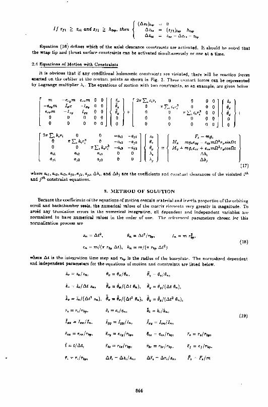
Equation (16j define• which of the axial clearance constraints ar~ activated. It should be noted that the wrap tip and thru•t •urface constraint. can be activated simultaneously or one at a. time.
2.4 Equations of Motion with Constraints
It io obvious tha.t if any conditional holonomic constraints are violal~d, there will be reaction forces exerted on theo orbiter at the <":f.nta.d points as shown in FiK. 2. Thl;'se couLrt~:t forces can be represented by La.gra.nge multiplier .x •. The equations of motion with two constraints; as an examplej a.re given below.
m -eq,rm e,.7'm 0 0
l zt;l'
l 2:>r I:. c,r, 0 0 0
j l j i. )' -eqm I~x ~l:r;tl 0 0 ii. 0 7r}: 1 c~r~ 0 0 e. ~.::.rm -!~" I•• 0 0 o. + 0 0 1r L.:~ c,r~ 0 e.
0 0 0 0 0 0 0 0 0 0 0 0 0 0 0 0 0 0 0 0 0 0
21rE,k,r1 0 0 -a~~ .,, l j Zo
H F,- mg"
l 0 :>rL,k,r~ 0 -a,2 -a1a 9. M. m,g,.e.C.fl - ec:l;m02rr;J.!innt 0 0 ,. I:, k,r~ -ad -a,J e. My+ mg<e"" + e"'m!l2 r.co$!1!
ai:l "·• "•J 0 0 .\, b.b, a,l ai2 a,, 0 0 .\, b.b;
( 17)
where a, 1 , a.12, a13, 4jl, t1j21 a1J, 6b,, and. dbj are the coefficients and constant clearances of the violated ith and j'h constraint equations.
3. METHOD OF SOLUTION
Because the coefli<ients ofthP equation. of motion rnnta.in m>tPri>l """ inPrtia prnpPrliPs ofthP orbiting scroll a.nd ba.ckchunber seals, the numerical va.lups of the matrix PlemPnts vary greatly in magnitude. To a.void any truncation errors in the numerical inte!i!;ra.tion, all dE>pcndeTJI and independent variables are normalized to ha.ve numerical values in the order of onE". Th~t> rE'fPrf"nr-=-d parameters chosen fnr this normalization proceos are
(18) c.,= mf(:>r r&p b.t), k, = m/(7r r., t>t2
)
where .O.t io the integration time etep and r&p is the radius of the baseplate. The normalized dependent a.nd independent parameters for the equations of motion and cunstra.ints are listed below.
Za = Zo/ Zn, e~ = e~;e .. , e, = e.;o.,,
.<. = z./ b.t z.., li. "' 9~/(b.t o.,), li. = e.f(b.t e.,),
i. = 'i0 /(b.t2 z.,), e."' 8./(6!2 e .. ), e. = o.J(b.t' o .. ),
f, = r,/r&p, ii = c.,/c"Pu k; "' k,jk.,, (19)
i%% .:: I '.I!:&/ In, iyy = lwfl.,, f •• = 1 •• 1 1.,,
ec:r: = et:::r: 1 r~tp, ... = """; • .,, ea = ~~.!/rbp, i'0 = r0 /r&p,
i = tjb.t, Th ::::=: Tt./Tbr;n r,. = .,.; • .,, e1 = eJir,.,
f, = r,(r.,, b.i; = b.z;/ >.,, b.r, = b.r,f z.,, F, = F,/m
866
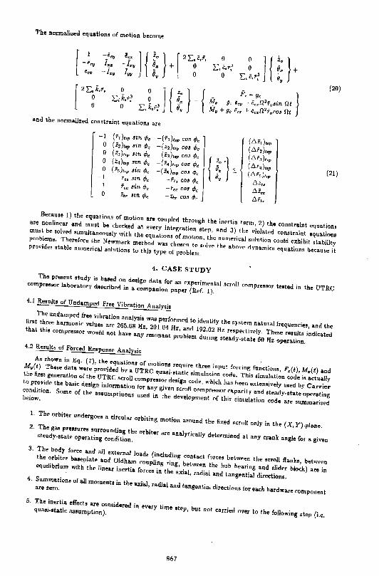
The normalized equation• of motion become
and the normalized constraint equations are
-1 (rdto~ "" tPo -( "' ) ... cos ¢. 0 ( .iiz ),.p •in tPo -(i2)top cos ¢. 0 (z,)u, "".Po (iJ)hp CIM ,P, 0 (z,),.. sm ¢< -(z4 ),,, cos <Po 0 (is),., .<in <Pc -(z,),., co• <Pc
-I ft;, 8t'tl. 4lr:: -ft.:~~ ClM t/Jr:: l fc:c .!in rPc: -Fe~ C.O& c/Jc 0 Zlw $In tPe -z~w co.< ,P,
0 L:.<.r~
0 L~.r~ ] { :: } +
f', - g< 1ft~ - 9r: €cy " Cczfl 2Tt~Jin Ot ,;ly + 9c etiZ I· eeo!!l 2
faC03 .Ot
(C.z-I).,, (C.f, ) .. ,
{ rl (C.r,J,.
:; (C.r,),.. (C.r,),,
/}it.
~i<!f! i'.fh.
} (20)
(21)
Because l) the equations of motion a.re coupled through the inertia t•rm, 2) the constraint equations are nonlinear and must be checked at every integn•tion et~p, and 3) the violated constraint equations must be solved •imultaneou•ly with the equations of motion, the numerical snluti<•n could exhibit stability problems. Therefore the Nt"'wmark meth()d was choeen to snlvP tht?" abnv{' ri ynamics equations because it provides stable nuiUerical •olutions to this type of problem_
4. CASE STUDY The pre•ent study is ba.sed on design data. for an experiment.al •~roll compre3SOr teoted in the UTRC
compre••or la.bor .. tory described in a companion paper (Ref. !). 4.1 Re•ulto of Undamped Free Vibration Analysis
The undamped free vibration a.na.lysia vra.s performed to identify the systern natural frequencies, and the first three harmonic values are 265.68 Hz, 201.04 Hz, and 192.02 Hz respecti•ely. These results indicated that thi• compresoor would not have any resonant problem during stea.dy·state 60 Hz operation. 4.2 Results of Forced Re•ponse Analysis
As shown in Eq. (7), the equations of motions require three input fnrcing functiono, F,(t), M.(t) and M.( t). These data vrere provided by a. UTRC quasi·otatk simulation code. This simulation cod,. is actually the first generation of the UTRC scroll compressor design code, which has been exlen•ively uoed by Carrier to provide the basic design information for any given scroll mmpressor capadty a.nd steady-state operating condition. Some of the assumptiuons used in the development of this simulation code are summarized below.
1. The orbiter undergoeo a circular orbiting motion around the fixed ocr<>U only in the (X, Y)-plane. 2_ The ga• pre•sures !Urrounding the orbiter are analytically determined a l a.ny crank angle for o. given steady.state openting condition.
3. The body force and all external loads (including contact force• belw<.,n the ocroll flanks, between the orbiter basepla.tP and Oldham coupling ring, between the hub bearing and slider block) are in equilibrium with the linear inertia. forces in the axial, radial and tang~ntial directions. 4. Summation• of all moments in the axial, radial a.nd tangential directions for each hardware component are zero.
5. The inertia. effect• are considered in every time •tep, but nr.l carried over to the following step (i.e. qua..i.static as•umption).
867
With these a.osumptiono, both the axial component of the reartinu fnrre from Jb<ed scroll and the force
center required for preventing the orbiter from undergoing axi"l mot.inn were romputed. These data were
converted into F,(t), M.(t) and M.(t) forth present study. Hnw•ver, in or<ler to acc~pt the experimental
preooure data from any oteady-state or transient uperations, p"rtions <.,f the original sirnulation code were
modified and integrated with the present model for use in predicting \he I ransient dynamics for any given
orbiting scroll design.
A set of the computed and measured pressures for the entire compression process for the same steady·
state condition is shown in Fig. 4. Good agreement betwoon the two are indicated. The presoures for a.U
compteuiot'1 pnckeh a.nd backcha.mber at a.ny given crank an~lf', for on~ re-volution, can be easily derived
from these data, and reoulto are shown in 5. These data are used fnr rompnting the three forcing functions
and the results are shown in Fig. 6.
The effects of ~hermal and pressure loads on the axial growth ,,f orbiting and fixed scroll wraps for
various compt'essor opE"ratin~ conditions are undf'r continuing .'ltndy. Prf:'liminary reBulh l"Jf a. finite e-lement
structurala.nalyois indicated that the mal<imum a.l<ial growth always nrrurrorl at the inMr tip of the scroll
wrap and the predicted numerical value was approl<imately 0.()011 in for the test condition (Ref. 5).
Based on this preliminary result and the design contours of the two srrnll wrap h~ights, the axial contact
constraint point (i.e. corresponding to \ 1 in Fig. 2) would occur near lh<" inner tip of the scroll wrap
and cause the orbiter to undergo small wobbles. The predicted nrbitiug srroll wobble cho.ra.cterislics based
on this wrap tip constraint for two high pressure, high load, steady-stale oper,.,ting conditions are shown
in Fig. 7a., and those obtained from the experimental study are shown in Fig. 7b. Good agreement
between the two is indicated. Both the &naly\ical and experimental results have indicated that the orbiter
wobble motions are quite small, and ~he experimental results sh<>wed no impact on the operation of \hie
E!xperimenta.l compreel!!ior.
S. CONCUJSIONS
Results of this study indin•ted that thewra.p height contours ofhnlh tho nrhiting and fixed scrolls, which
vary with compressor operating e<>nditions, play an important r<>le in the s\ udy of orbiter dynamics. The
importance of conetra.into in the dyn .. mic an .. lyois of a given nrbitcr closign is shown The mnd~l pr~sented
io capable of predicting the orbiter dynamics of axial motion for stea.d.v-state or start-up operation if the
wrap heights of both the fixed and orbiting scrollo, the thrust sur(ac~, beanng and seal dearences, and tl!e
preuure data. surrounding the orbiting scroll are pr~scribed.
6. ACKNOWLEDGEMENT
The authors would lik~ to thank M~ssro. D.G. Cutts, R.L. DeBlois. A . .l. Marchese, D.J. McFarlin and
J.J. Nieter of UTRC and Mr. T. Kassouf of Carrier for their discussions, suggestions and comments
during the course of this study.
REFERENCES
1. Ma.rcheoe, A.J., "Dynamics of An Orbiting Scroll with Al<ial Ooutpliance, Part - 2 Experimental
Techniques", presented a.t the 1992lnt. Compressor En!\. Conf. at purdue, July 12-14, 1992.
2. Niet~r, J.J. a.nd T. Barito, "Dyn&mics o( Compliance Mechanisms in Snoll Compressors, Part l:
Axial Compliance" Proceeding of 1990 Int. Compressor ~Jng. Conf. al Purdue, Vol. 1, pp. 308-316.
3. Ishii, N. et a.l., "Dynamic Behavior of a Scroll Compreooor", .ISME International J. Series Ill, Vol.31,
No. I, 1988.
4. Morishita., E. et a.l., "Scroll Compressor Dynamics", llull<-tin of .ISM E, Vol. 29, No. 248, Feb. 1986.
5. Marler, M.E. and K.B. Kumar, "[)~termination of Scroll Wrap Contarl Stresses Using the Boundary
Element Method", presented a.t the 1992lnt. Compressor Eng. Con f. at purdue, July 12-14, 1992.
868
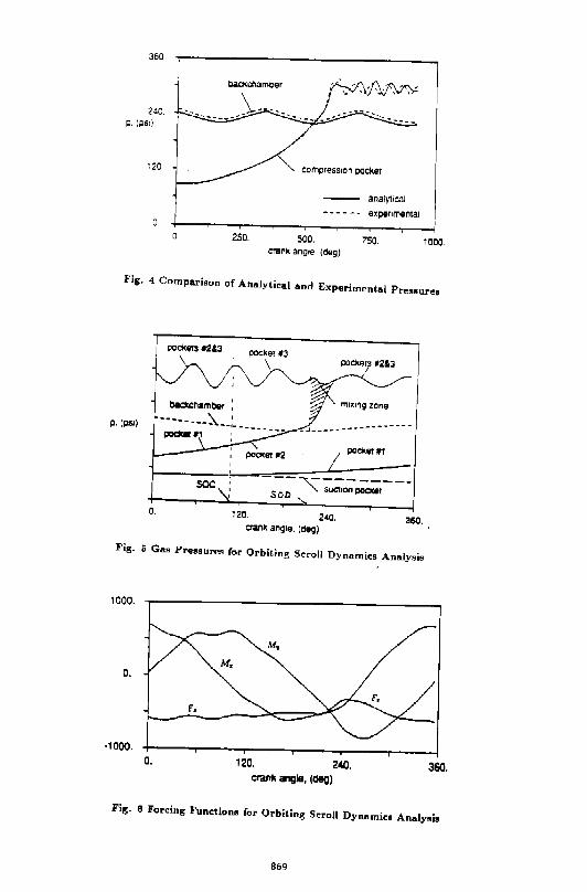
360
240. p. (PSI)
120
o.
bild<c~amber
compress1on pocket
250. 500. crank angle (deg)
analytical
expe'lm&ntal
750. 1000.
Fig. 4 Comparioon of Analyti~al and Experimental Pre~•ureo
pockets •2&3
p. (!:lSI)
0. 120. 2"0. 360. crank angle. (c:l~~g)
Fig. 5 Gao Pre~oureo for Orbiting S"roll Dynamics Analy•is
1000.
0.
·1000. 0. 120. 240. 360.
crank angle, (deg)
Fig. 6 Forcing Functions for Orbiting Scroll Dynamics Analysis
869
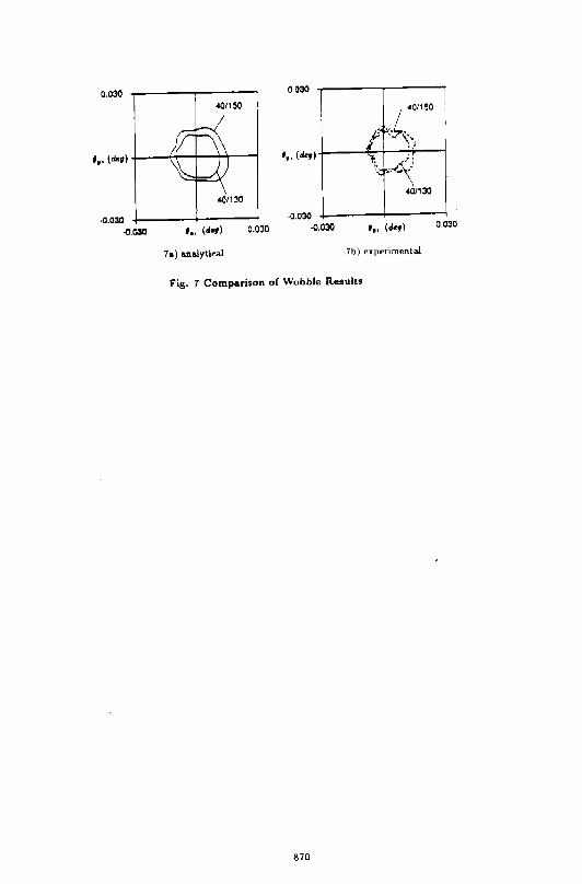
0.030
.0.030 .0.030
.0/150
'·· (d<f) 0.030
0.030
'·· (d<t)
-0.030 ·0.030
p I
• ' 40/150
k:. '>~ ';: :--'\ ··:.:
.0/130
'·· (de,) 0.030
7 .. ) ana.lytica.l 7b) experimenta.l
Fig. T Comparison of Wobble R"•ults
870
DYNAMICS OF AN ORBITING SCROLL VITO AXIAL COMPLIANC:S Part 2 - Experimental Techniques
Anthony J. Har~hese (203)727-7785
Assistant Research Engineer
United Technologies Research Center Silver Lane - H.S. 19 East Hartford, CT 06108
ABSTRACT
In scroll compressors equipped with axial compliance mechanisms, the orbiting scroll may be exhibit axial motion, particularly during transient conditions at startup and shutdown. An experimental effort was undertaken to measure the instantaneous pressures acting on, and the rigid body motion of, an axially compliant orbiting scroll. For a rigid body, the <x,y,z> coordinates of any three points are sufficient to describe rigid body motion. Accordingly, three proximity probes lo~ated approximately 120 degrees apart, were installed beneath the orbiting scroll to measure the axial position of three points on the underside of the orbiting scroll baseplate. The remaining x and y coordinates were available from geometry and instantaneous crank angle measurement. High response axial compliance pressure, high response compression chamber pressures, and proximity probe data were acquired for various operating conditions at steady state, startup and shutdown. Results indicated that the duration of o~bi ting scroll "wobble" at transient startup conditions was a function of compliant chamber volume, port diameter and seal configuration. A computer model was written to optimize the compliance chamber to essentially eliminate the duration of orbiting scroll wobble during compressor startup. During compressor shutdown, the orbiting scroll remained stable.
NOMBNCLATIIRB
Constant volume specific heat of refrigerant, btu/lbm-R. Diameter of compliance chamber supply line, in. Roughness of compliance chamber supply line, in. Enthalpy of gas entering compliance chamber, btu/lbm. Length of compliance chamber supply line, in. Instantaneous mass in compliance chamber, lbm. Instantaneous flow rate into compliance chamber, lbm/s. Instantaneous pressure in compliance chamber, psia. Instantaneous pressure in compression chamber, psia. Instantaneous temperature in compliance chamber, R. Instantaneous temperature in compression chamber, R. Time, s.
3 Compliance chamber volume, in Velocity of gas entering compliance chamber, ft/s. Axial displacement of orbiting s~roll baseplate, in. Total axial clearance between scroll elements, in. Instantaneous density of gas in compliance chamber, lb/in3•
INTRODUCTION
In order to obtain high efficiency in a scroll compressor, some means of minimizing tip leakage is necessary. One method of minimizing tip leakage is to incorporate seals into the tips of the scroll flanks [1]. A second approach is to pressurize a cavity located beneath an axially compliant orbiting scroll. This approach generates an upward force on the orbiting scroll greater than the downward force generated by gas compression [2). A third approach entails pressurizing a cavity above an axially compliant fixed scroll creating a downward force on the fixed scroll which is in excess of the upward pressure forces created by gas compression (3].
871
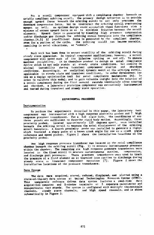
For a scroll compressor equipped vith a compliance chamber beneath an
axially compliant orbiting scroll, the primary design criterion is to provide
enough upvard force beneath the orbiting scroll to not only o~ercome the
dovnvard compression force, but to counteract the orbiting scroll o~erturning moment as vell. An optimum design vould accomplish these functions vith a
minimum of excess upvard force so as to minimize friction betveen the scroll
elements. Upvard force is generated by bleeding high pressure compression
and/or discharge gas through the orbiting scroll baseplate into the compliance
chamber.[4,5] If insufficient force is generated by the compliant chamber,
even for a portion of the cycle, the orbiting scroll can become unstable,
resulting in axial vibrations, or "vobble".
Much vork has been done to ensure stability of the orbiting scroll during
steady state operation. In typical compressor applications, hovever, a scroll compressor vill spend much of its lifetime cycling on and off. To ensure
maximum reliability, it is therefore prudent to design an axial compliance
device vhich is not only stable at steady state conditions, but results in
minimal instability during transient compressor startup and shutdown
conditions. Accordingly, an analytical dynamic model of the orbiting scroll,
applicable to steady state and transient conditions, is under development for
use as _a design optimization tool for axial compliance mechanisms [6]. In order to validate this model, and to gain valuable insight into the behavior of
a scroll compressor during the first se~eral seconds immediately after startup
and shutdovn, a laboratory prototype compressor vas extensively instrumented
and tested during transient and steady state operation.
EXPERIMENTAL PROCEDURE
Instrumentation
To perform the experiments described in this paper, the laboratory test compressor vas instrumented vith 4 high response proximity probes and 7 high
response pressure transducers. For a 3-D rigid body, the coordinates of any three points are sufficient to describe rigid body motion. Accordingly, three
proximity probes, located approximately 120 degrees apart, vere installed
beneath the orbiting scroll to measure the axial displacement of the orbiting scroll baseplate. A fourth proximity probe vas installed to generate a signal vhich featured a sharp pulse at a knovn crank angle for use as a crank angle
reference and speed pickup. Figure 1 shovs the installation locations of the proximity probes.
One high response pressure transducer vas located in the axial compliance
chamber beneath the orbiting scroll (Fig. 1) to measure instantaneous pressure
vithin the chamber. The remaining six high response pressure transducers vere
located in the fixed scroll to measure instantaneous suction, compression.
and discharge port pressures. These pressure transducers vere used to track the pressure of a fluid element as it traveled from suction to discharge during
steady state or transient compressor operation [7]. Figure 2 shovs the
installation locations of the pressure transducers.
Data System
The data vere acquired, stored, reduced, displayed, and plotted using a
state-of-the-art data system at United Technologies Research Center (UTRC). This completely software driven data system features a real-time data
acquisition computer and X-vindov terminals at 5 separate calorimeter and
desuperheater test stands. The system is configured vith multiple thermocouple
channels, steady state channels, and high speed channels, and is shovn
schematically in Figure 3.
872
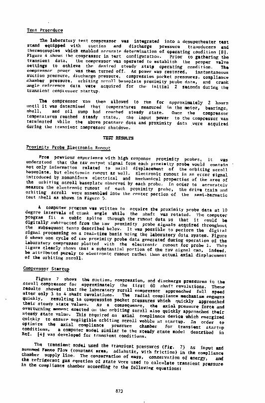
Test P~ocedure
The laboratory test compressor was integrated into a desuperheater test stand equipped with suction and discharge pressure transducers and thermocouples which enabled accurate determination of operating condition [8]. Figure 4 shows the compressor in test configuration. Prior to gathering the transient data, the compressor was operated to establish the proper valve settings to achieve the desired steady stat~ operating condition. The compressor power was then turned off. As power was restored, instantaneous suction pressure, discharge pressure, compression pocket pressures, compliance ~hamber pressure, orbiting scroll baseplate proximity probe data, and crank angle reference data were acquired for the initial 2 seconds during the transient compressor startup.
The compressor was then allowed to run for approximately 2 hours until it was determined that temperatures measured in the motor, bearings, shell, and oil sump had reached steady state. Once the compressor temperatures reached steady state,. the input power to the compressor was terminated while the above pressure data and proximity data were acquired during the transient compressor shutdown.
TEST RESULTS
Proximity Probe Electronic Runout
From previous experience ~ith high response proximity probes, it was understood that the (aW output signal from each proximity.probe would contain not only information related to axial displacement of the orbiting scroll baseplate, but electronic runout as well. Electronic runout is an er(or signal introduced by nonuniform electrical and mechanical properties of the area of the orbiting scroll baseplate observed by each probe. In order to accurately measure the electronic runout of each proximity probe, the drive train and orbiting scroll were assembled into the center portion of the semi-hermetic test shell as shown in Figure 5.
A computer program was written to acquire the proximity probe data at 10 degree intervals of crank angle vhile the shaft vas rotated. The computer program fit a cubic spline through the runout data so that it could be digitally subtracted from the raw proximity probe signals acquired throughout the subsequent tests described below. It was possible to perform the digital signal processing on a real-time basis using the laboratory data system. Figure 6 shows one cycle of raw proximity probe data generated during operation of the laboratory compressor plotted with the electronic runout for probe 1. This figure clearly shovs that a substantial portion of the raw signal can, indeed, be attributed purely to electronic runout rather than actual axial displacement of the orbiting scroll.
Compressor Startup
Figure 7 shows the suction, compression, and discharge pressures in the scroll compressor for approximately the first 60 shaft revolutions. These results showed that the laboratory scroll compressor approached full speed after only 3 to 4 shaft revolutions. The radial compliance mechanism engages quickly, resulting in compression pocket pressures which quickly approached their steady state values. As a consequence, the axial pressure force and overturning moment exerted on the orbiting scroll also quickly approached their steady state value. This required an axial compliance device which energized quickly to ensure negligible orbiting scroll wobble at startup. In order to optimize the axial compliance pressure chamber for transient startup conditions, a computer model similar to the steady state model described in Ref. (4] was developed for transient conditions.
The transient model used the transient pressures (Fig. 7) as input and assumed Fanno Flo~ (constant area, adiabatic, with friction) in the compliance chamber supply line. The conservation of mass, conservation of energy, and the ref~igerant gas equation of state were used to calculate transient pressure in the compliance chamber according to the following equations:
873
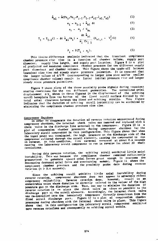
m(Pci,Tci,Pi-l'Ti-l'dsl'lsl,esl)
mi ~ mi-l + msl 6t
Pi a mi I Vbc
6t msl Tis Ti-1(1- 6t msl/mi) + (hsl,i + vi/2)
mi evi-l
(1)
(2)
(3)
(4)
(5)
Tbis finite-difference analysis indicated that the transient compliance
chamber pressure rise time is a function of chamber volume, supply port
diameter, supply line length, and supply port location. Figure 8 is a plot
of predicted and measured compliance chamber pressure for two different supply
port diameters and chamber volumes. This figure shows the trade-off between
transient rise time and s~eady state pressure pulsation. It is apparent that
the larger values of d/V~ (corresponding to larger line size and/or smaller
compliance chamber volume) result in faster initial pressure rise and larger
steady state pressure pulsations.
Figure 9 shows plots of the three proximity probe signals during transient
startup conditions for the two different geometries. The normalized axial
displacement z/z shown in these figures is the displacement of the orbiting
scroll baseplate from the bottom of the fixed scroll surface divided by the
total axial clearance between the fixed and orbiting scrolls. This figure
indicates that the duration of orbiting scroll instability can be minimized by
minimizing the compliance chamber pressure rise time.
Compressor Shutdown In order to exaggerate the duration of reverse rotation encountered during
compressor shutdown, the internal check valve was removed and replaced with a
check valve in the discharge line external to the compressor. Figure 10 is a
plot of compression chamber pressures during compressor shutdown for the
laboratory scroll compressor in this configuration. This figure shows that when
the input power was terminated, the high pressure on the discharge side of the
compressor relieved through the scroll elements, causing the compressor to ·run
in reversf!. At this condition, flow revE!rsal occurred- at about 0.4 seconds
causing the laboratory scroll compressor to run in reverse for about 30 shaft
revolutions.
During this reverse rotation, the orbiting scroll exhibited little axial
instability. This was because the compliance chamber remained sufficiently
pressurized to gE!nerate upward axial forces great enough to overcome th"
decrf!asing downward axial force and overturning moment. Figure 11 shows ~he
compliance chamber pressure and the proximity probe data during reverse
rotation (t > 0.4 seconds).
Since the orbiting scroll exhibits little axial instability during
reverse rotation, compressor shutdown does not appear to adversely effect
compressor reliability. Reverse rotation does, however, result in an
undesirable noise whose duration is directly related to the volume of the high
pressure gas on the discharge side. Thus, one way to minimize the duration of
reverse rotation is to place the check valve as close as possible to the
discharge port of the scroll elements. Accordingly, the internal check valve
vas re-installed into the laboratory compressor directly downstream from the
fixed scroll discharge port. Figure 12 is a plot of compression chamber
pressures during shutdown with the internal check valve in plaee, This figure
shows that in this configuration the laboratory scroll compressor exhibited
zero reverse rotations and consequently no orbiting scroll wobble.
874
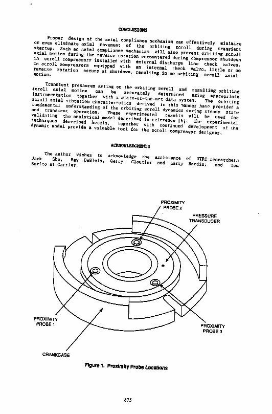
CONCLUSIONS Proper design of the axial compliance mechanism can effectively minimize or even eliminate axial movement of the orbiting scroll during transient startup. Such an axial compliance mechanism will also prevent orbiting scroll axial motion during the reverse rotation encountered during compressor shutdown in scroll compressors installed with external discharge line check valves. In scroll compressors equipped with an internal check valve, little or no reverse rotation occurs at shutdown, resulting in no orbiting scroll axial motion.
transient pressures acting on the orbiting scroll and resulting orbiting scroll axial motion can be accurately determined using appropriate instrumentation together with a state-of-the-art data system. the orbiting scroll axial vibration characteristics derived in this manner have provided a fundamental understanding of the orbiting scroll dymamics during steady state and transient operation. These experimental results will be used for validating the analytical model described in reference (6). The experimental techniques described herein, together with continued development of the dynamic model provide a valuable tool for the scroll compressor designer.
The author wishes to Jack Shu, Ray DeBlois, Barito at Carrier.
CRANKCASE
ACICNOVLEDGIIBN'I:S
acknowledge the assistance Gerry Cloutier and Larry of UTRC researchers Hardin; and Tom
PROXIMITY PR08E2
Figure 1. Proximity Probe Locations
875
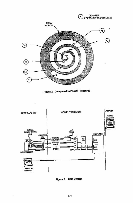
0 DENOTES PRESSURE TRANSDUCER
TEST FACILITY
SIGNAL CONDITIONING
FIXED
Figure 2. Compression Pocket Pressures
COMPUTER ROOM
=,..__ _ __._.---.,.....'== ~~~==r-~=~~~~
X.V41NOOW TERMINAl
~~y====<:~ til
SPEEO
Figure 3. Data System
876
OFFICE
WORK
·g
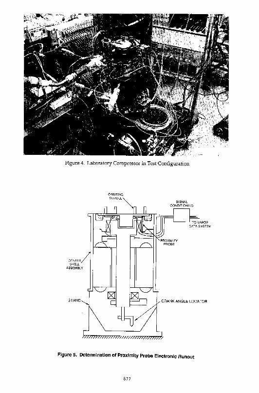
Figure 4. Laboratory Compressor in Test Configuration
CE:NTER SHE.LL
ASSEMBLY
Figure 5. Determination of Proximity Probe Electronic Runout
877
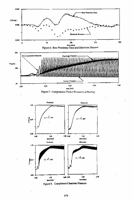
0.060
.. -11.060 -1-----.-----.,......-----,----..---""T'"---...,......---,.------i
o.
35!1.
200.
so. 0.00
1.00
~0.67 ..
o.w
90. 180. 270. 360.
·-(degl Figure 6. Raw Proximity Data and Electronic Runout
0.30 0.60 0.90 1.20
ti-1=1
Figure 7. Compression Pocket Pressures at Startup
Measured
2.00
1.00 2.00 o.w 1.00 .....,,_) _,_, Figme 8. Co!llpliance Chamber Pressure
878
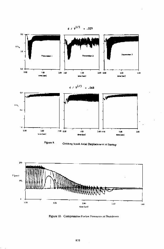
z/zF.
o.s
0.00 1.00
bnu:IMCI
o.o I~iiiiiiiiiiiiiiiii•••~ ~
05
10 +---~~---r----~--~
d 1 v113 ~ .o29
z.oo 0.00
d I yl/J ~ .068
--~~ . -····-~
' I
0.00 t.OO
llnnclsecl 2.1J) 0.00 2.00 om tOO
~ ... ,...,,
''"'-
()2fl
Figure9.
11.50
Orbiting ScroU Axial Displacement at Startup
""" tim~lsccl
1.10
figure 10. Compression l'ocketl'ressurcs at Shutdown
879
2.UO
2.00
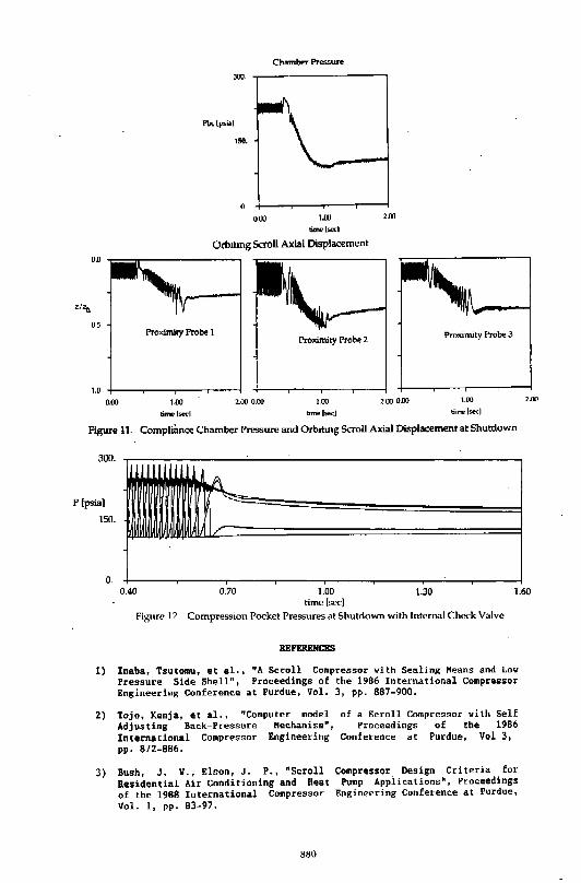
Chambor Pr<!ssuro 300.
ISO.
0.
000 1.00 2.00
dme(>od
Otbiting Scroll Axial Displacement
0.0
05 Proximity Probe I
Proximity Probe 2 Proximity Probe 3
1.0
0.00 1.oo 2.(](1 0.00 1.00 2.00 0.00 1.00
time lse('] time 1~1 tiTm!' (st"C)
Figure 11. Complmnce Chamber Pressure and Orbiting Scroll Axial Displacement at Shutdown
300.
p (psia)
150.
0.
/
2.00
0.40 0.70 1.00 time lsecl
1.30 1.60
Figure> 12. Compression Pocket Pressures at Shutdown with Internal Check Valve
REPERENCES
1) Inaba, Tsutomu, et al., "A Scroll Compressor with Sealing Heans and Low fressure S1ae Shell", Proceedings of the 1986 International CompressoT Engineering Conference at Purdue, Vol. 3, pp. 887-900.
2)
3)
Tojo, Kenja, et al., "Computer model Adjusting Back-Pressure Mechanism", International Compressor Engineering pp. 872-886.
Bush, J. V., Elson, J, P., "Scroll Residential Air Conditioning and Heat of the 1988 International Compressor Vol. 1, pp. 83-97.
880
of a Scroll Compressor with Self Proceedings of the 1986
Conference at Purdue, Vol 3,
Compressor Design Criteria for Pump Appiications", Proceedings
Engineering Conference at Purdue,
4) Nieter, J. J., and Bari to, Tom, "Dynamics of Compliance Mechanisms for Scroll Compressors, Part I: Axial Compliance", Proceedings of the 1990 International Compressor Engineering Conference at Purdue, Vol. 1, pp. 308-316.
5) Nieter, J. J., Marchese, A. J., and DeBlois, R. L., "Dynamic Axial Compliance to Reduc:e Thrust Surface Friction in a Scroll Compressor", Proceedings of the 1992 International Compressor Engineering Conference at Purdue.
6)
7)
B)
Shu, H. T., and Perac:chio, A, A., with Axial Compliance, Part 1:
"Dynamics of an Orbiting Scroll Simulation of Orbiter Motion", compressor Engineering conference Proceedings of the 1992 International
at Purdue.
DeBlois, R. L., and Stoeftler, R. c., "Instrumentation and Data Analysis Techniques for Scroll Compressors", Proceedings of the 1988 International Compressor Engineering Conference at Purdue, Vol. 1, pp. 182-188.
McGovern, J. A., "Analysis Incorporating Hot Gas Bypass Exchanger", Proceedings of the Conference at Purdue, Vol 1.,
of a Refrigerant Compressor Load Stand and a Single Full Condensation Heat
1984 International Compressor Engineering pp. 468-4 77.
881
JOURNAL BEARING PERFORMANCE IN A SCROLL COMPRESSOR
Hiromu NARUMIYA *, Keiju SAKAINO**, Masahiko OIDE**
* Central Research Laboratory Mitsubishi Electric Corporation
8·1-1 Tsukaguchi Honmachi, Amagasaki, Hyogo 661, JAPAN Tel.: 81-6-497-7164 Fax: 81-6-497-7291
** Shizuoka Works, Mitsubishi Electric Corporation
ABSTRACT The load carrying capacities of the main and sub bearings were obtained by mathematical analysis when a main shaft supported by two journal bearings is flexed by the action of plural loads. This analytical method was applied to a typical scroll compressor, and the basic perfonnance of the bearings was calculated at selected frequencies. The misalignment tolerance and optimum bearing clearance ratio of the main and sub bearings were quantitatively evaluated, and meaningful guidelines for bearing design were obtained.
INTRODUCTION High efficiency, low operating noise and low vibration characteristics have made the scroll compressor<'>, together with the screw compressor, leading candidates to succeed today's reciprocating and rolling piston type compressors for many applications. A scroll compressor is typically constructed with a bearing supporting an orbiting scroll outside the two bearings supporting the main shaft. Because the load on the main shaft acts outside of the two support bearings, the load tends to bend the main shaft. In addition, the presence of assembly error in the position of these two bearings (i.e., the main and sub bearings) causes the main shaft to rotate in a twisted manner through the two bearings, so that the main bearing has to operate under extreme conditions.
The use of a roller bearing as the main bearing has been proposed as a means of reducing this twisting of the main shaft, with a ball bearing or needle bearing used for the sub bearing. As a result, there are few examples of journal bearings being used for both the main and sub bearings, and few reports in the literature regarding journal bearings other than one on experimental studies of the edge load(2) and another on ways of reducing the bearing reaction force through optimization of a counterweight.(3) There are virtually no reports about calculating the effect of bearing performance on overall scroll compressor performance with specific consideration given to the bending of a main shaft supported by journal bearings. The authors report in this paper on the development of a program to obtain the overall load carrying capacity of the main and sub bearingS' when a main shaft
883
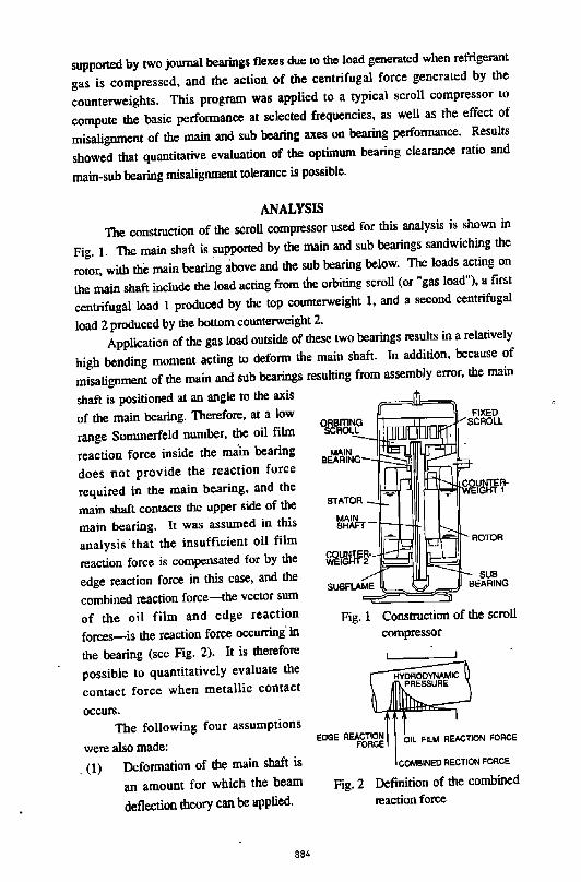
supported by two journal bearings flexes due to the load generated when refrigernnt
gas is compressed, and the action of the centrifugal force generated by the
counterweights. This program was applied to a typical scroll compressor to
compute the basic performance at selected frequencies, as well as the effect of
misalignment of the main and sub bearing axes on bearing performance. Results
showed that quantitative evaluation of the optimum bearing clearance ratio and
main-sub bearing misalignment tolerance is possible.
ANALYSIS
The construction of the scroll compressor used for this analysis is shown in
Fig. 1. The main shaft is supported by the main and sub bearings sandwiching the
rotor, with the main bearing above and the sub bearing below. The loads acting on
the main shaft include the load acting from the orbiting scroll (or "gas load"), a first
centrifugal load 1 produced by the top counterweight 1, and a second centrifugal
load 2 produced by the bottom counterweight 2.
Application of the gas load outside of these two bearings results in a relatively
high bending moment acting to deform the main shaft. ln addition, because of
misalignment of the main and sub bearings resulting from assembly error, the main
shaft is positioned at an angle to the axis
of the main bearing. Therefore, at a low
range Sommerfeld number, the oil film
reaction force inside the main bearing
does not provide the reaction force
required in the main bearing, and the
main shaft contacts the upper side of the
main bearing. It was assumed in this
analysis that the insufficient oil film
reaction force is compensated for by the
edge reaction force in this case, and the
combined reaction force--the vector sum
of the oil film and edge reaction
forces-is the reaction force occurring' in
the bearing (see Fig. 2). It is therefore
possible to quantitatively evaluate the
contact force when metallic contact
occurs.
The following four assumptions
were also made:
. (1) Deformation of the main shaft is
an amount for which the beam
deflection theory can be applied.
884
MAIN BEARING
SUB BEARING
Fig. 1 Construction of the scroll
compressor
OIL FILM REACTION I'ORCE
COMBINED RECTION FORCE
Fig. 2 Definition of the combined
reaction force
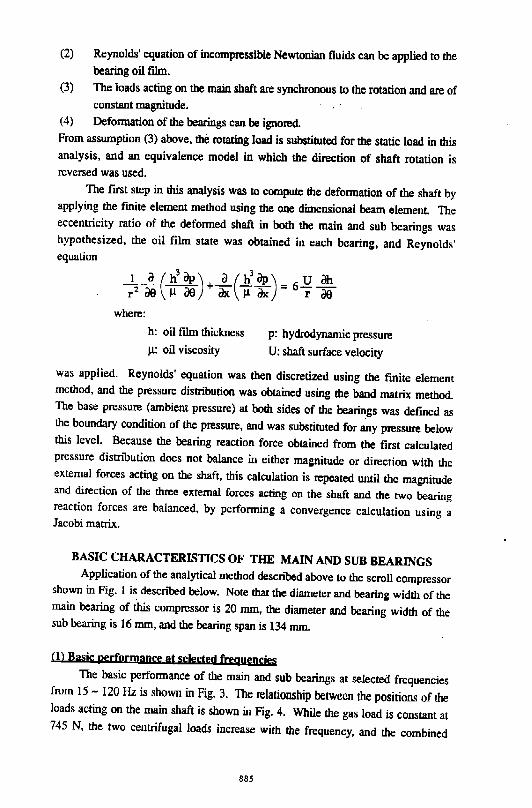
(2) Reynolds' equation of incompressible Newtonian fluids can be applied to the bearing oil film.
(3) The loads acting on the main shaft are synchronous to the rotation and are of constant magnitude. , - ' , '
(4) Defonnation of the bearings can be ignored. From asswnption (3) above, the rotating load is substituted for the static load in this analysis, and an equivalence model in which the direction of shaft rotation is reversed was used.
The first step in this analysis was to compute the defonnation of the shaft by applying the fmite element method using the one dimensional beam element. The eccentricity ratio of the defonned shaft in both the main and sub bearings was hypothesized, the oil film state was obtained in each bearing, and Reynolds' equation
where:
h: oil film thickness
)..l: oil viscosity
p: hydrodynamic pressure
U: shaft surface velocity
was applied. Reynolds' equation was then discretized using the finite element method, and the pressure distribution was obtained using the band matrix method. The base pressure (ambient pressure) at both sides of the bearings was defined as the boundary condition of the pressure, and was substituted for any pressure below this level. Because the bearing reaction force obtained from the first calculated pressure distribution does not balance in either magnitude or direction with the external forces acting on the shaft, this calculation is repeated until the magnitude and direction of the three external forces acting on the shaft and the two bearing reaction forces are balanced, by performing a convergence calculation using a Jacobi matrix.
BASIC CHARACTERISTICS OF THE MAIN AND SUB BEARINGS Application of the analytical method described above to the scroll compressor
shown in Fig. I is described below. Note that the diameter and bearing width of the main bearing of this compressor is 20 mm, the diameter and bearing width of the sub bearing is 16 mm, and the bearing span is 134 mm.
(I) Basic performance at selected frequencies The basic perfonnance of the main and sub bearings at selected frequencies
from 15- 120Hz is shown in Fig. 3. The relationship between the positions of the loads acting on the main shaft is shown in Fig. 4. While the gas load is constant at 745 N, the two centrifugal loads increase with the frequency, and the combined
885
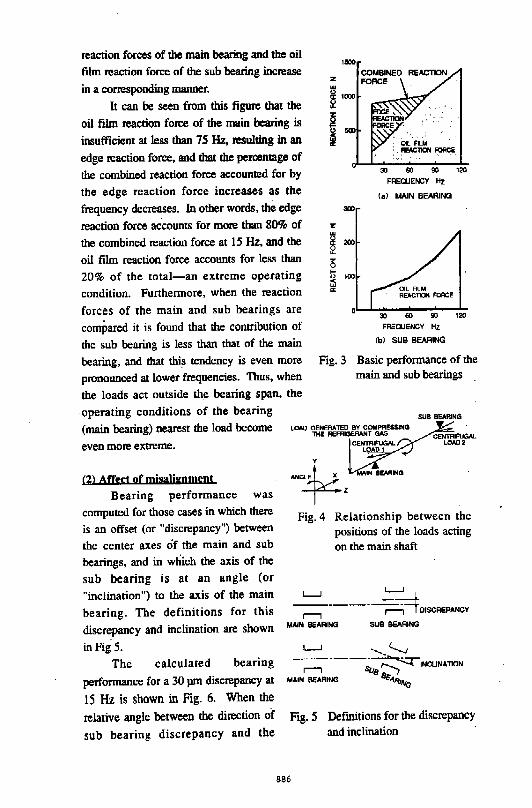
reaction forces of the main bearing and the oil
film reaction force of the sub bearing increase
in a corresponding manner.
1500
l.in.'iU.
It can be seen from this figure that the
oil film reaction force of the main bearing is
insufficient at less than 75 Hz, resulting in an
edge reaction force, and that the percentage of
the combined reaction force accounted for by
the edge reaction force increases as the
frequency decreases. In other words, me edge
reaction force accounts for more than 80% of
the combined reaction force at 15 Hz, and the
oil film reaction force accounts for less than
20% of the total-an extreme operating
condition. Furthermore, when the reaction
forces of the main and sub bearings are
compared it is found that the contribution of
the sub bearing is less than that of the main
bearing, and that this tendency is even more
pronounced at lower frequencies. Thus, when
the loads act outside the bearing span, the
operating conditions of the bearing
REACTlON FORcE
(main bearing) nearest the load become
even more extreme.
(2) Affect of mjsaUgnment
Bearing performance was
computed for those cases in which there
is an offset (or "discrepancy") between
the center axes of the main and sub
bearings, and in which the axis of the
sub bearing is at an angle (or
"inclination") to the axis of the main
bearing. The definitions for this
discrepancy and inclination are shown
inFig5.
The calculated bearing
performance for a 30 pm discrepancy at
15 Hz is shown in Fig. 6. When the
relative angle between the direction of sub bearing discrepancy and the
' .
OIL-~~----_.--~ 30 60 90 1;!11
FREQUENCY Hz
(a) MAIN BEARING
300
z w
~ 200
i5 ;:: 0
i1i 100
a:
30 ilO 90 1;!11
FREQUENCY l-Iz
(b) SUB BEARING
Fig. 3 Basic performance of the
main and sub bearings
lOAO OENERATED BY COMPRESSING lliE REFRIGERANT GAS
Fig. 4 Relationship between the
positions of the loads acting
on the main shaft
L.....J L.....J
~---· r---i-4 DISCREI'IlNCY
MAIN BEARING SUB BEARING
L.....J ........ ~ ~---~~INCLINA110N
MAIN BEARING 8E-4Rtftta
886
Fig. 5 Defmitions for the discrepancy
and inclination
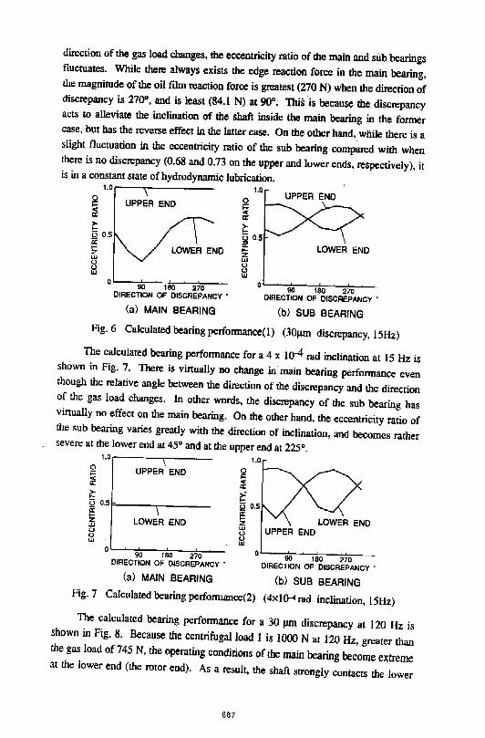
direction of the gas load changes, the eccentricity ratio of the main and sub bearings fluctuates. While there always exists the edge reaction force in the main bearing, the magnitude of the oil film reaction force is greatest (270 N) when the direction of discrepancy is 27fP, and is least (84.1 N) at 90°; ·This is because the discrepancy acts to alleviate the inclination of the shaft inside the main bearing in the former case, but has the reverse effect in the latter case. On the other hand, while there is a slight fluctuation in the eccentricity ratio of the sub bearing compared with when there is no discrepancy (0.68 and 0.73 on the upper and lower ends, respectively), it is in a constant state of hydrodynamic lubrication.
1.0 1.0 UPPER END 0
~ a:
~ 0 0.5 a;
UPPER END 0 ;:; ~ ~ Q 0.5 a: !Z LOWER END !Z LOWER END
UJ (.) (.) UJ
0 90 180 270
DIRECTION OF DISCREPANCY "
(a) MAIN BEARING
UJ
8 UJ
oL---90+---~180~~2±~---orRECTION OF DISCREPANCY "
(b) SUB BEARING
Fig. 6 Calculated bearing performance(l) (30J.Un discrepancy, 15Hz)
The calculated bearing performance for a 4 X w-4 rad inclination at 15Hz is shown in Fig. 7. There is virtually no change in· main bearing performance even though the relative angle between the direction of the discrepancy and the direction of the gas load changes. In other words, the discrepancy of the sub bearing has virtually no effect on the main bearing. On the other hand, the eccentricity ratio of the sub bearing varies greatly with the direction of inclination, and becomes rather severe at the lower end at 45° and at the upper end at 225°.
0 ;::: < a:
I:
1.0.--------,~---
UPPER END
0 0.51=-----r-----~ z UJ (.) 0 UJ
LOWER END
o~~~go~~,so~~2±~~-DIRECTION OF DISCREPANCY "
(a) MAIN BEARING
~ < a: ~
1.0
0 0.5
~ z UJ (.) (.) UJ
oL-~~oo---,eLo~-2~7o---DIREcrroN OF DISCREPANCY "
(b) SUB BEARING Fig. 7 Calculated bearing performance(2) (4xl~ rad inclination, 15Hz)
The calculated bearing performance for a 30 pm discrepancy at 120 Hz is shown in Fig. 8. Because the centrifugal load 1 is 1000 Nat 120 Hz, greater than the gas load of 745 N, the operating conditions of the main bearing become extreme at the lower end (the rotor end). As a result, the shaft strongly contacts the lower
887
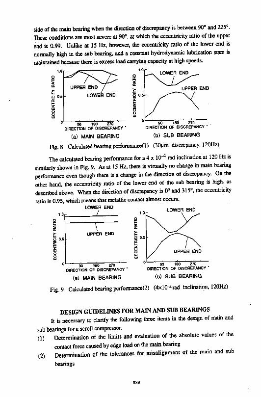
side of the main bearing when the d~ction of discrepancy is between 90° and 225°.
These conditions are most severe at 90°, at which the eccentricity ratio of the upper
end is 0.99. Unlike at 15 Hz, however, the eccentricity ratio of lhe lower end is
nonnally high in the sub bearing, and a constant hydrodynamic lubrication state is
maintained because !here is excess load carrying capacity at high speeds.
~ 8 0.5 a: ... z Ill 0
ill
LOWER END
0 90 180 270 DIRECTION OF DISCREPANCY '
(a) MAIN BEARING
1.0
~ a:
!; !.! 0.$
~ 0 0 Ill
UPPER END
0 90 180 270 DIRECTION OF DISCREPANCY ' ..
(b) SUB BEARING
Fig. 8 Calculated bearing performance(!) (301J.I11 discrepancy, 120Hz)
The calculated bearing perfonnance for a 4 x 10⁴ rad inclination at 120 Hz is
similarly shown in Fig. 9. As at 15Hz, there is virtually no change in main bearing
performance even though there is a change in lhe direction of discrepancy. On lhe
other hand, the eccentricity mtio of the lower end of the sub bearing is high, as
described above. When lhe direction of discrepancy is oo and 315°, lhe eccentricity
mtio is 0.95, which means that metallic contact almost occurs.
LOWER END 1.01-___ ...._ __ _
Q ... ... a:
r= 0 0.5 a: !Z Ill 0 0 Ill
UPPER END
0 90 180 270 DIRECTION OF DISCREPANCY '
(a) MAIN BEARING
·LOWER END
UPPER END
0 90 180 270 DIRECTION OF DISCREPANCY '
(b) SUB BEARING
Fig. 9 Calculated bearing perfonnance(2) (4xlQ-4rad inclinati'?n, 120Hz)
DESIGN GUIDELINES FOR MAIN AND SUB BEARINGS
It is necessary to clarify the following three items in the design of main and
sub bearings for a scroll compressor. ·
(l) Detennination of the limits and evaluation of the absolute values of the
contact force caused by edge load on the main bearing
(2) Detennination of the tolerances for misalignment of the main and sub
bearings
888
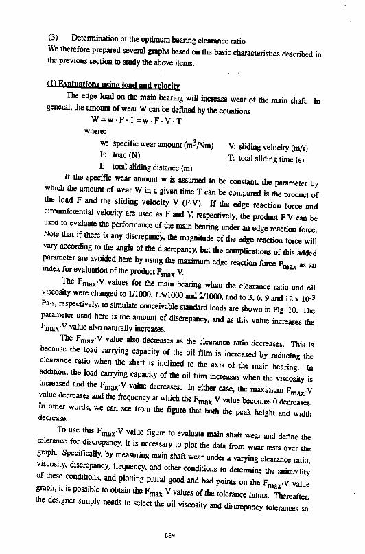
(3) Detennination of the optimum bearing clearance ratio We therefore prepared several graphs based on the basic characteristics described in the previous section to study the above items.
,,
(1) Eyaluatjons usjng Joad and yelocitv The edge load on the main bearing will increase wear of the main shaft. In general, the amount of wear W can be defmed by the equations
W:w·F·l =w·F·V·T where:
w: specific wear amount (m3 /Nm) F: load (N) 1: total sliding distance (m)
V: sliding velocity (m/s) T: total sliding time (s)
If the specific wear amount w is assumed to be constant, the parameter by which the amount of wear W in a given time T can be compared is the product of the load F and the sliding velocity V (F· V). If the edge reaction force and circumferential velocity are used as F and V, respectively, the product F·V can be used to evaluate the perfonnance of the main bearing under an edge reaction force. Note that if there is any discrepancy, the magnitude of the edge reaction force will vary according to the angle of the discrepancy, but the complications of this added parameter are avoided here by using the maximum edge reaction force Fmax as an index for evaluation of the product Fmax·V. The Fmax·V values for the main bearing when the clearance ratio and oil viscosity were changed to 1/1000, 1.5/1000 and 2/1000, and to 3, 6, 9 and 12 x I0-3 Pa·s, respectively, to simulate conceivable standard loads are shown in Fig. 10. The parameter used here is the amount of discrepancy, and as this value increases the Fmax·Y value also naturally increases. The Fmax·Y value also decreases as the clearance ratio decreases. This is because the load carrying capacity of the oil film is increased by reducing the clearance ratio when the shaft is inclined to the axis of the main bearing. In addition, the load carrying capacity of the oil film increases when the viscosity is increased and the Fmax·V value decreases. In either case, the maximum Fmax·V value decreases and the frequency at which the Fmax· V value becomes 0 decreases. In other words, we can see from th~ figure that both the peak height and width decrease.
To use this Fmax·Y value figure to evaluate main shaft wear and defme the tolerance for discrepancy, it is necessary to plot the data from wear tests over the graph. Specifically, by measuring main shaft wear under a varying clearance ratio, viscosity, discrepancy, frequency,· and other conditions to determine the suitability of these conditions, and plotting plural good and bad points on the Fmax·V value graph, it is possible to obtain the F max· V values of the tolerance limits. Thereafter, the designer simply needs to select the oil viscosity and discrepancy tolerances so
889
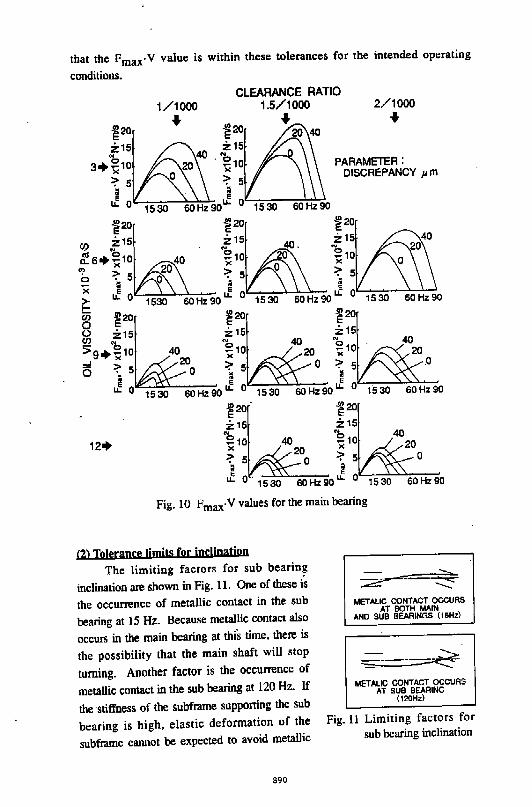
that the Fmax·V value is within these tolerances for the intended operating
conditions.
CLEARANCE RATIO 1/1000 1.5/1000
f,s %15
2/1000
+ .!!!20~+ ~20~+ 20 40
"' 40 "' 3+ ~10 20 . ~10 PARAMETER:
=?' 5 0 :;- 5 DISCREPANCY Jl. m
~ ~ u.. 0 1530 60Hz90u.. 0 1530 60Hz90
~20~ ~20~ ~20~ co z1s z1s 40 z15 4o
ell 0 . .. . .. 20
c..s+-1o 40 ~1o 20 ~10 "' >< 20 >< 0 >< 0
a =?'5 o :;-5 :;-5 ... li ; ;
>< E e e
~ ; 2:~1530 60Hz9o;;~1530 60Hz90;;~1530 60Hz90
~ z15 z15 z15
- ~ ~ 40 b . 40
~9+"";10 4020 ";10 20 ";10 20
0- :;- 5 o :;- 5 0 :;- 5 D K
; ~
e e e
u.. 0 1530 60Hz90u.. 0 1530 60Hz90u.. 0 1530 60Hz90
!~~· 40,. !~~20 :;- 5 0 :::- 5 0
~ i u.. 0 1530 60Hz90u.. 0 1530 60Hz90
12+
Fig. 10 Fmax·Y values for the main bearing
(2) Tolerance Jjmjts for jpc!inatjon
The limiting factors for sub bearing
inclination are shown in Fig. 11. One of these is
the occurrence of metallic contact in the sub
bearing at 15 Hz. Because metallic contact also
occurs in the main bearing at this time, there is
the possibility that the main shaft will stop
turning. Another factor is the occurrence of
metallic contact in the sub bearing at 120 Hz. If
the stiffness of the subframe supporting the sub
bearing is high, elastic deformation of the
subframe cannot be expected to avoid metallic
890
METALIC CONTACT OCCURS AT BOTH MAIN
AND SUB BEARINGS (15Hz)
METALIC CONTACT OCCURS AT SUB BEARING
(120Hz)
Fig. 11 Limiting factors for
sub bearing inclination
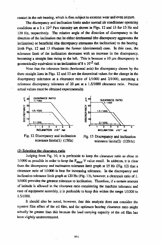
contact in the sub bearing, which is then subject to extreme wear and even seizure.
The discrepancy and inclination limits under nonnal air conditioner operating
conditions at a 3 x lQ-3 Pa-s viscosity are shown in, Figs. 12 and 13 for 15 Hz and
120 Hz, respectively. The relative angle of the direction of discrepancy to the
direction of the inclination can be either detrimental (the discrepancy aggravates the
inclination) or beneficial (the discrepancy attenuates the inclination) to the bearing.
Both Figs. 12 and 13 illustrate the fonner (detrimental) case. In this case, the
tolerance limit of the inclination decreases with an increase in the discrepancy,
becoming a straight line rising to the left. This· is because a 10 pm discrepancy is
geometrically equivalent to an inclination of 8 X 10·5 rad.
Note that the tolerance limits (horizontal axis) for discrepancy shown by the
three straight lines in Figs. 12 and 13 are the theoretical values for the change in the
discrepancy tolerance at a clearance ratio of l/1000 and 2/1000, assuming a
reference discrepancy tolerance of 20 pm at a 1.5/1000 clearance ratio. Precise
actual values must be obtained experimentally.
2/1000 ---·--·-·~
1 • 2 3 • 5 6 INCLINATION x1 o·• rad
Fig. 12 Discrepancy and inclination tolerance limits(l) (15Hz)
(3) Se!ectjng the clearance ratjo
CLEARANCE RATIO f--------...1/1000
___ 1.!..!!!1?2.. ___ _ 0~~1~~2~~3~~~~5--6~
INCLINATION x1o·• rad
Fig. 13 Discrepancy and inclination tolerance limits(2) (120Hz)
Judging from Fig. 10, it is preferable to keep the clearance ratio as close to
l/1000 as possible in order to keep the Fmax·V value small. In addition, it is clear from the discrepancy and inclination tolerance limit graph at 15 Hz (Fig. 12) that a
clearance ratio of l/1000 is best for increasing tolerance. In the discrepancy and
inclination tolerance limit graph at 120Hz (Fig. 13), however, a clearance ratio of I.
5/1000 provides the greatest tolerance to inclination. Therefore, if a certain amount
of latitude is allowed in the clearance ratio considering the machine tolerance and
ease of equipment assembly, it is preferable to keep this within the range l/1000 to
1.5/1000.
It should also be noted, however, that this analysis does not consider the
squeeze film effect of the oil film, and the optimum bearing clearance ratio might
actually be greater than this because the load carrying capacity of the oil film has been slightly underestimated.
891
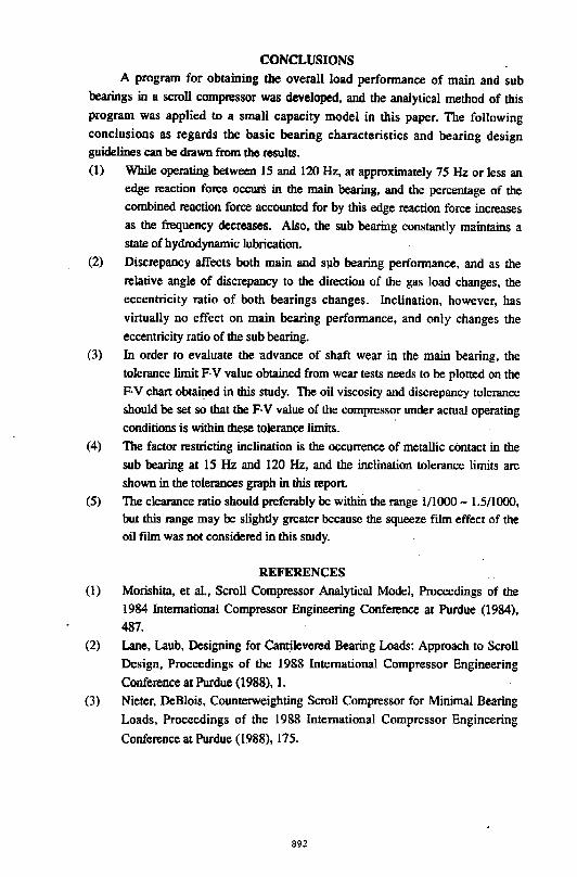
CONCLUSIONS A program for obtaining the overall load perfonnance of main and sub
bearings in a scroll compressor was developed, and the analytical method of this program was applied to a small capacity model in this paper. The following conclusions as regards the basic bearing characteristics and bearing design guidelines can be drawn from the results. (I) While operating between 15 and 120Hz, at approximately 75Hz or less an
edge reaction force occurS in the main bearing, and the percentage of the combined reaction force accounted for by this edge reaction force increases as the frequency decreases. Also, the sub bearing constantly maintains a state of hydrodynamic lubrication.
(2) Discrepancy affects both main and S\lb bearing perfonnance, and as- the relative angle of discrepancy to the direction of the gas load changes, the eccentricity ratio of both bearings changes. Inclination, however, has virtually no effect on main bearing perfonnance, and only changes the eccentricity ratio of the sub bearing.
(3) In order to evaluate the advance of shaft wear in the main bearing, the tolerance limit F-V value obtained from wear tests needs to be plotted on the F· V chart obta~ed in this study. The oil viscosity and discrepancy tolerance should be set so that the F· V value of the compressor under actual operating conditions is within these tolerance limits.
(4) The factor restricting inclination is the occurrence of metallic contact in the sub bearing at 15 Hz and 120 Hz, and the inclination tolerance limits are shown in the tolerances graph in this report.
(5) The clearance ratio should preferably be withm the range 1/1000- 1.5/1000, but this range may be slightly greater because the squeeze ftlm effect of the oil film was not considered in this study.
REFERENCES (l) Morishita, et al., Scroll Compressor Analytical Model, Proceedings of the
1984 International Compressor Engineering Conference at Purdue (1984), 487.
(2) Lane, Laub, Designing for Cantilevered Bearing Loads: Approach to Scroll Design, Proceedings of the 1988 International Compressor Engineering Conference at Purdue (1988), 1.
(3) Nieter, DeBlois, Counterweighting Scroll Compressor for Minimal Bearing Loads, Proceedings of the 1988 International Compressor Engineering
Conference at Purdue (1988), 175.
892
TRE MECHANICAL ANALYSIS OF A SCROLL COMPRESSOR
Yongzhang Yu , Yuhua Xu , Liansheng Li (XI'AN JIAOTONG UNIVERSITY. P.R.CHINAJ
ABSTRACT Based on thermodynamic and mechanical models. the axial and tangential forces acting on the orbiting scroll and their balance methods are discussed in this paper. Besides, a detailed analysis of orbiting mechanism of three Pins is carried out too.
INTRODUCTION The advantageous characteristics of scroll compressor have been pr1>ved in theory and experiment [ 1
] [ 3
] in rer.ent years. Remarking the main influences of the axial and tangential forces acting on orbiting scroll on the performance and reliability, ~his paper puts forward a new balancing ~ethod and compares it with the balance means used. The mathematical model and computer program of scroll compressor working process [ 2] arr app] ied to the calculation of this paper.A proloLYPf! of scrol I for air condition has been developed and tr.sted by authors. The calculated results and experimental results are consistent
THE AXIAL AND TANGENTIAL GAS FORCES ACTING ON ORBITING SCROLL ~ith crank shaft rotation, the center of orbiting scroll is ,pushed around lhe center of fixed scroll or crank shaft. As the gas in the sealed volumetric chambers. which are composed of the orbiting and fixed scroll. is compressed, the gas Pressure increases and the orbiting scroll is forced. With the thermodyamic mathmatic model [ 2
] and the mechanical model. the gas force exerting model is shown in rig.l. In rig.] a). because the pushing force PN T of crank shaft and the tangential gas force P~ t arc not acted on the same point, thus makes the orbiting scroll rotate in itsself, the normal compression chambersare interfered, self·rotation moment is given by
11)
In terms of Fig.] bl, the axial gas force F,.. acting on lhe orbiting scroll makes the orbiting scroll departure the fixed scroll, increasing the axial clearance Ct.and resulting in apparent decrease of volumetric efficiency.
893
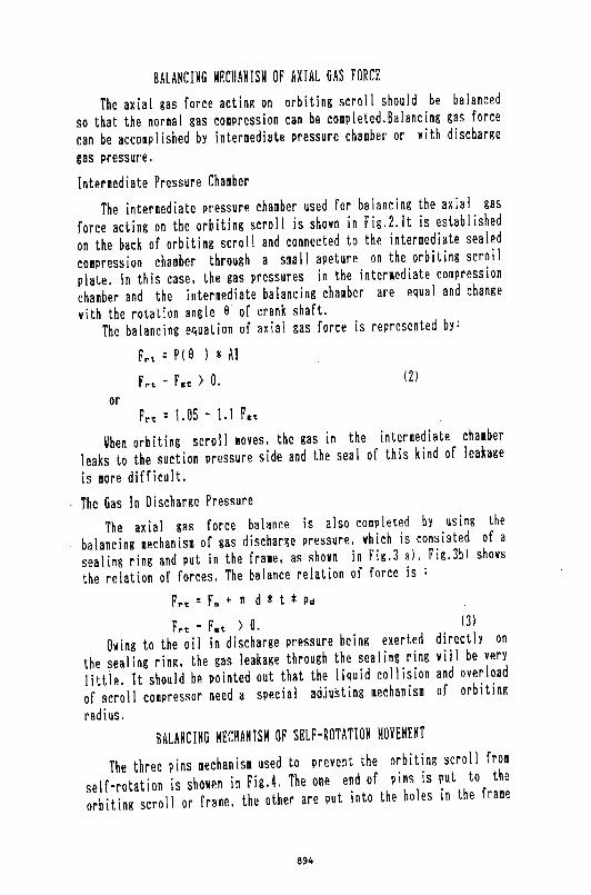
BALANCING MECHANISM OF AXIAL GAS FORCE
The axial gas force acting on orbiting scroll should be balanced
so that the normal gas compression can be completed.Balancing gas force
can be accomplished by intermediate pressure chamber or with discharge
gas pressure.
Intermediate Pressure Chamber
The intermediate pressure chamber used for balancing the axial gas
force acting on the orbiting scroll is shown in Fig.2. It is established
on the back of orbiting scroll and connected to the intermediate sealed
compression chamber through a small apeture on the orbiting scroll
plate. In this case, the gas pressures in the intermediate compression
chamber and the intermediate balancing chamber are equal and change
with the rotation angle a· of crank shaft. The balancing e~uation of axial gas force is represented by:
F rt = P ( 9 ) * A 1
f rt - F ct ) 0. (2)
or Frt = 1.05 - 1. I Fct
When orbiting scroll moves. the gas in the intermediate chamber
leaks to the suction pressure side and the seal of this kind of leakage
is more difficult.
The Gas In Discharge Pressure
The axial gas force balance is also completed by using the
balancing mechanism of gas discharge pressure, vhich is consisted of a
sealing ring and put in the fra11e, as shovn in Fig.3- a), Fig.3b) shows
the relation of forces. The balance relation of force is :
F rt : F.. + n d * t * Pd
F,.t - Fct > 0. (3)
Owing to the oil in discharge pressure being exerted directly on
the sealing ring, the gas leakage through the sealing ring vill be very
littie. It should be Painted out that the liquid collision and overload
of scroll compressor need a special adjusting mechanism of orbiting
radius.
BALANCING MECHANISM OF SELF-ROTATION MOVEMENT
The three pins mechanism used to prevent the orbiting scroll from
self-rotation is showen in Fig.4. The one end of pins is put to the
orbiting scroll or frame, the other are put into the holes in the frame
894
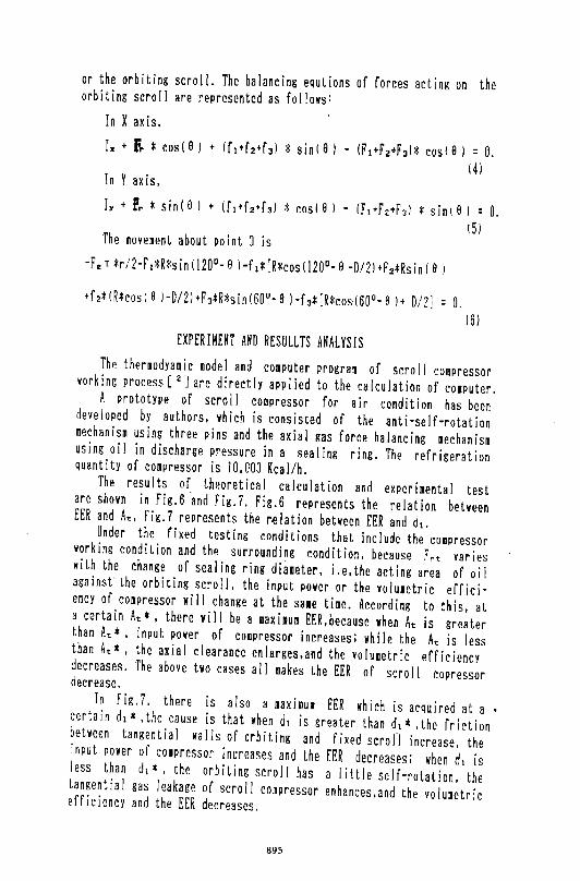
or the orbiting scroll. The balancing equlions of forces acting on the orbiting scroll are represented as follows:
In X axis.
I~ • fr *cos( a J • !ft•f2•faJ *sin! a I - (~\•F2+Fal* coste J = 0. (4)
In Y axis,
r. + Pr *sin( e) + (ft+f2+f3) *cos( 8) - (Ft•F'2+F3) *sin I 8) : 0. ( 5)
The movement about point 0 is -F.t *r/2-Ft*R*sin!l20°-8 )-ft*[R*cos(J20°-8 -D/2l+F2*Rsin(8 J
+f2*(R*cosi8 J-D/2J+FJ*R*sin(60°-9 l-f3*[R*r.os·(60°-8 l+ D/2] = 0. (6)
EXPERIMENT AND RESULLTS ANALYSIS The thermodyamic model and coaputer program of scrol I compressor working process [ 2] are directly applied to the calculation of computer. A Prototype of scroll compressor for air condition has been developed by authors. which is consisted of the anti-self-rotation mechanism using three pins and the axial gas force balancing mechanism using oil in discharge pressure in a sealing ring. The refrigeration quantity of compressor is 10,000 Kcal/h. The results of theoretical calculation and experimental test are shown in Fig.6 ~nd Fig.7. Fig.6 represents the relation between EER and At, Fig.7 represents the r~lation between EER and dt. Under the fixed testing eonditions that include the compressor working eondition and the surrounding condition, because F,t varies with the ehange of sealing ring diameter. i.e,the acting area of oil against· the orbiting scroll. the input power or the volumetric efficiency of compressor will change at the sa1e time. According to this, at a certain At*, there viii be a maximum EER,because when At is greater than At*, input power of compressor increases; while the At is less than At*, the axial clearance enlarges. and the volumetric efficiency decreases. The above two cases all makes the EER of scroll copressor decrease. In Fig. 7. there is also a maximum EER which is acquired at a • certain dt *,the cause is that when dt is greater than d1 *,the friction between tangential walls of orbiting and fixed scroll increase. the
input power of compressor increases and the EER decreases; when d1 is less than d1 *. the orbiting scroll has a 1 ittle self-rotation. the tangential gas leakage of scroll compressor enhances.and the volumetric efficiency and the EER decreases.
695
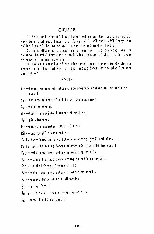
CONCLUSIONS
1. Axial and tangential gas forces acting on the orbiting scroll have been analysed. These two forces will influence efficiency and reliability of the compressor, it must be balanced perfectly,
2. Using discharge pressure in a sealing ring is a easy way to balance the axial force and a optimizing diameter of the ring is found by calculation and experiment.
3. The self-rotation of orbiting scroll may be prevented·bY the pin mechanism and the analysis of the acting forces on the pins has been carried out.
SYMBOLS
A~---theacting area of intermediate pressure chamber on the orbiting sera IIi
At---the acting area of oi I in the sealing ring;
Ct---axial clearancei
d ---the intermediate diameter of sealing;
d~---pin diameter;
D ---pin hole diameter W=dl + 2 * rl i EER---energy efficiency ratio;
ft.f2,fJ---friction force between orbiting scroll and pinsi
Ft.Fz,FJ---the acting forces between pins and orbiting scroll:
rEt---axial gas force acting On Orbiting SCrolli
F,. T -- 4 tangential gas force acting on orbiting scroll;
f'N T ---pushed force of crank shaft i
F~---radial gas force acting on orbiting scroll;
Fr,---pushed force of axial direction;
~s---spring foreei
lx. [y---inertial force of orbiting scroll:
Ms---mass of orbiting scroll;
896
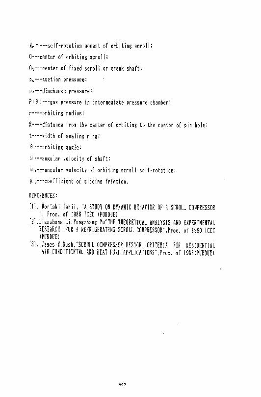
Mr T ---se If-rotation moment af orbiting sera]]: 0---center of orbiting scroll: 01--·center of fixed scroll or crank shaft: p~·--suction pressure: Pd---discharge pressure: PIS )---gas Pressure in intermediate Pressure chamber: r··--orbiting radius: R----distance from the center of orbiting to the center of Pin hole: t----width of sealing ring; 8 ---orbiting angle: w ---angular velocity of shaft; w ~---angular velocit.y of orbiting scroll self-rotation: ~ o--·coefficient of sliding friction.
REFERENCES: :r. Horiaki Ishii, "A STUDY ON DYNAMIC BEHAVIOR OP A SCROLL COMPRESSOR
", Proc. of 1986 ICEC (PURDUE I :z~.Liansheng Li.Yongzhang Yu"THE THEORETICAL ANALYSIS AND EXPERIMENTAL
RESEARCH FOR A REFRIGERATING SCROLL COMPRESSOR",Proc. of 1990 ICEC IPURDUEI .
'3]. James W.Bush,'SCROLL COMPRESSOR DESIGN CRITERIA FOR RESIDENTIAL ;rR CONDITIONIN~ AND HEAT PUMP APPLICATIONS",Proc. of 1988iPURDUEl
897
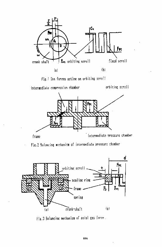
fit
crank shaft fixed scroll
(a) (bl
Fig. I Gas forces acting on orbiting scroll
intermediate compression chamber orbiting scrol I
frame intermediate pressure chamber
Fig.2 B~lanc:ing mechanism of intermediate pressure chamber
(a)
fra1e
spring
cranhhaft
Fig.3 Balancing mechanism of axial gas force.
898
(b)
d
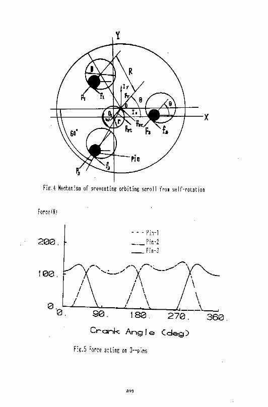
y
rig.4 Mechanism of preventing orbiting scroll from self-rotation
Force(N)
200.
100.
- - - Pin-1 Pin-2
_ Pin-3
.- .,.....-., ,-..._ / ....... r ,. .......... , . """" X' ......__ .............. ._.. '
I\ \
I ' I \ \
0~~.----~--~~--~\~--~--~~ 90 . 1 80 . 270 . 360 .
Crank Angle Cdeg)
Fig.5 Force acting on 3--pins
899
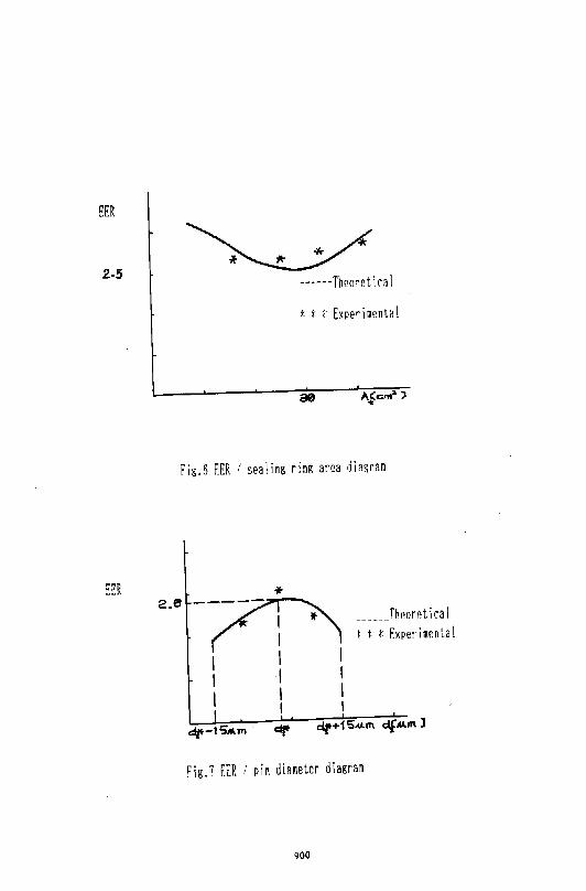
EER
2-5 ------Th0oretir~l
* * t Experiment~!
Fig.fi EER 1 sealing ring area diagram
* --~~ * _____ _Thi!orrtiral
~ ·- i ~ I t * Experimental
1 I I
2.6
I I I 1 I I
I I
Fig.? EER : pin diameter diagram
900
Use of Polymer Suction Valve in Piston on the Low Side Compressor
Prasanta K. Roy and Michael A. Di Flora Bristol Compressors, Bristol, VA (U.S.A)
ABSTRACT
Although plastic utilizatfon is abundant in the automotive industry and growing day by day, its usage is very limited, especially in the running gear of air conditioning and refrigeration compressors.
In recent years, different polymers have been developed by several manufacturers and the properties of some are suitable for use as a valve material for reciprocating compressors. In Inertia compressors, Kadel suction valves are utilized to attain high efficiency and reliability under wide range of compression ratios. For this reason, the Inertia compressor is very suitable for heat pump air conditioners.
INTRODUCTION
After the Energy Crisis, energy conservation has been the most important topic in the field of air conditioning. In the United states, the regulation of system efficiency started in 1992. Besides the governmental -regulations, higher efficiencies have been required from the distributors to meet the customer's needs concerning energy sa"ings.
In such a situation, there came a strong demand for higher efficiency compressors, because the improvement of compressor efficiency is the most economical method to increase unit efficiency in spite of technological difficulties. Thus, most compressor manufacturers have been eagerly improving conventional compressors and developing new ones.
The Inertia compressor is a new generation of reciprocating compressor, utilizing polymer suction and discharge valves.
This paper describes the properties, design, development, testing, and implementation of the polymer suction valves in the Inertia pump, which is one of the highest efficiency reciprocating compressors in the market today.
DESIGN FEATURE
The plastic valve when used dynamically in a compressor, running approximately five million cycles in 24 hours, is very critical and must have the physical and mechanical properties to withstand the cyclic loading, high. temperature, impact, and fatigue. High tensile strength (30,000 psi), low elongation (1.5%), high flexural modules (2.3 million psi) and high deflection temperature (634°F) are some of the key properties of the polymer suction valve material. Table I shows the characteristics of different polymers that have been evaluated for the Inertia compressors.
901
Kadel E-1230 (Polyarylethelketone, PAEK) has proven to be the most
suitable. The selected high-perfonnance thennoplastic is shown in Table 2.
Table 3 compares the strength of different polymers at room temperature.
Graphs 1 and 2 depict bending fatigue of Kadel E-1 000 at and reverse bending
fatigue of Kadel E-1230, respectively.
Availability, pricing, design, molding, and machining are also important
factors in the successful application of the suction valves (sho~ in Fig. 1).
Contrary to the standard practice of "Swedish Flapper Valve Steel"
suction valve on a steel valve plate, the polymer suction valves simply rest on
the inner and outer seats of the machined cast iron pistons. The retainer
screwed into the piston post controls the lift of the suction valve which is
optimized to achieve the desired efficiency and sound level of the compressor.
The suction gas is routed directly through the crankcase body into the
piston suction ports. The direct gas is much cooler (Fig. 2) and has less
pressure drop as it flows through the 360° opening of the suction valve. The
result is higher BTU/cubic inch (Fig. 3) and higher efficiency of the pump
(Fig. 4).
ENDURANCE TESTING
The different polymer valves have been evaluated to assure the
efficiency of the compressor. Also extensive endurance testing of the
different valves has been undenaken to select the final polymer, which is 30%
carbon reinforced PAEK. Finite element analysis has been used extensively
in designing the valve and correlated with the actual perfonnance and life
testing. A large database has been constructed. Life testing of Inertia
compressors at the different abuse and accelerated conditions is summarized
in Table4.
CONCLUSION
Control of base material (resin pallets) and molding process (humidity,
temperature control, melting, feeding, gating, and injection) must be perfected
to control porosity, shrinkage, cracking, and other problems during injection
molding. Machining to the fmal dimensioned valves is another milestone.
Matching the mating parts, e.g., piston seats and valve contact areas is very
critical to the perfonnance. By perfecting these features, the polymer valve
has been successfully implemented in the Inertia compressor.
ACKNOWLEDGEMENT
The authors would like to acknowledge the substantial contribution to
this paper by David Gilliam and Hugh Stringer. The authors also wish to
thank Bristol Compressor's upper management for their support and
permission to publish this paper.
902
REFERENCES
[1] High Performance Thermoplastic Resins and their Composites, Sylvie B'eland.
[2] 39!1! SPIRP/C Conference, ASTM D·67L
903
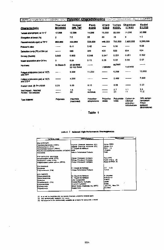
1··:,-w;!le:~?·(t:>:!.;-v.t~' ~"t-r>":.'.'- 't~.< ~\tt~#t+~~). ~~/,_~-~Polvmer! §hapcteristlcs-:: ~ :t.:, ;:-,=-~'"·<,',,~~,~,~, ~,,-~l "><"::> -!-'ifi.~ ox> :.'\1'-i,,~~.,~-q
Tharmld vespel Peek Ultam Tori on Shamban Chamcterlstle .M..!<iii.Q.Il ~ !.SJi. i.D..Q.Q !l2n ~
T-Sir0n!llh(Pl>)ol7:l'F 12.000 12,500 ,._500 15.000 22,000 31.000
EJon!IOIIDA a - ~~ 7.5 35 30 15
--(llolla73"F 650,000 •so.ooo 550,000 .. 0.000 730.000 2,600,000 --- 0 .• 1 0 .• 2 0.38
Oti10C:IIan 1orte>-rFl al264 psi 680 320 •20 532 ss•
De""'iY (lbslin:ll 0.0.9 0.052 o.o•a 0.0.7 0.051 0.051
Waler abSOIJIIIon aller 2• hro. 0.2. 0.15 0.28 0.33 0.06
liardnns 91 ShOre 0 •s-saRWE 86FlWE 92·1021lWM 110flWM 110flWM
Faliauo enclJr.lnco (1'511 0110171 6,000 11,500 6,000
and73'F
Faliguo lllllllrance tpsilot 10(71 anci275"F
•.ooo 2,.00
Fristion CDof.@ PY-25000 0.21 D-29 0.15 0.33
lsod lfi1IOC1 ; NO!OIIed 1.5 1.6 2.7 1.1
FHblln: Un-<101011ed 30 ..., break 20 , T)lllllolllerial Polylnido Polylnido Polyeu·••'~ Poty•lh•- Polyarndo· Carbo11 re-
(machined) etherkelone rirrldCI lrndo ittfotced polyelher-ethel1(etone
Table 1
TABLE < SOioelod HIQII-,.,r1ormon .. n..tmo,IOOIICO
II'OLYKE'tONI!S P.ly.lh•n~lhittlo,eiOR4 (PEEK) lm~&l~ Chltmlclil lnOtr.<lrl•s (ICI) PDI,elh•rk•lon• (PE)() Imperial Ch•m~cP lnduSitllt• UCI)
PDiy•tlwrl!•ll)(l6'1<1tiOn• ~PfOKK) E I 0~1 dill Nillft'IC'Jul&
P•ly.tllitrkiiiiOnllltr•rlurllln•kiiiiDnill (PEKE~!<) a.sF Poly"-i111en• Amoco PeriOrm~J~e~~ ~~s
POL YAR'Y'LE~E SULFIDES PaiJpt!,811~1•Nt ~ulhdill ~Pf'SJ PIII~~J~yt•ne 'iullldill ~P"Sl Pa~ph•flyi•n• :1Ul11(J• ~.,IIDn• (PPSS)
POLYAMIDE$;
Po~'f'lilllll:l. F'~;~irllllllm~rmdlt ~P.&,I)
IPOL'I'IMIDES P~Mr;atylltn•lmldli
~lyar~itnillimldl
POI)'ItruQ•
Palyitlllitllmld• (PI:,I) POifillllli!rlimidl Polr"-~l•;mnrdo
F'oiJIIei!MIId'
Pllllllpl P•t••l•um C!inlp~y Pt~UIIPI Pltlr ... um Campanr PlnMipS PltliOIItum C1tmpanr
EIO~dltNitlmU!s "mt;W;4oP.rtrJI'IiiMIGIIIPIOiiui:ls
E.l DI,IJDft'l dlt NlmDina E. I DuJ:mtll dli NMM~.~Ja E1hrl CoJpo•1111Dn Gene1111EIItc1r~~~:~
Am"l(;lnC,anamll:l lllii:w~ TOiUSIII (:hMI!K:m lm:.(MTC) ROQIItliC:;lrp
(I) lli Of wdl b• a9'illllabll onl~ ~ Bi!ilom llnl5trH t;DIIIpM!te malert.t ,..1$ (2) NmcomiiHiita•IIJ ... ltil~l• bul n••rl-, ('J) Not 1~1...t 10 be c:ommon:I•Uy •vit!labllt 1:5 1 ~rl• ~ CICIRIPQ• mll.lilliiU
904
Vll;!r•.1 PEEK V~tol~• PEK PEKK ~I)
Ulirilp•• ·-AykmPPS RyiA:In PAS-2 (~)
Rylan 5 PPSS (2)
J 2 (1.:1) TrukJfl
1<-POI'tm•r N-Polym•& rnMJ Uijltm
c""' LMc:-TP~, Nill~~t·TPI Ourlmld
Kadel JiJ..G.Q
30,000
1.5
2.300,000
0.32
63•
0 052
0.02
12,000
7.000
0.20
1.5 11.2
30% cattJon rt1n1orced PAEK (poly;uy~ tlhorkelone)
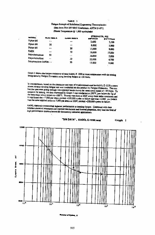
12000
'""""
:_
i ...., • u
1 c li
....,
TUU: 3 Falip S~m~p of Reillfotet:d Eni!Uioerifts Thenmplasties
(<!ala from 39111 SPl RP/C Coaf......,.,, ASTM 0-671) (RoamT~@ 1,800~)
... -Nylon 6/6 Nylon 6/6 Nylcm 6/6 PAEK
30
30 PQJye<llofSulfone Po1yclhersulfone Po1ypbcnylcnc Sulfide • •
30 30
30 30
STRJ;l'IGTH, PSI .... eteiD .&I 7C''IC'LI:S
JAOO 3,100 1.000 s.!IOO
13.000 18,000 16.000 22.000 13.000
8,000 17,000 s.ooo 6.700 9.SOO
Gr>ph 1 sbo"'• lhc fatiSU•I1:Sistlnco of nw KADEL E-1000 lln>ollllCIIlperiiiR vnlh lhc =ins bcinJ done by FlliiiJC Dynamics using bendins f:uigucu-30 Hm<.
In oonsiderauon, ba.<cd on lhc cltemi:ilry and type of reiof_,. used ill KA!lll. E-1230. a IIICft sov= ~· bcndin1 fa!lcuc """ was condlml:d on this pmduot by Fali&ue Dynamics. 'nlis test has lhc spcc:tmon goin, lhroush ooo opposed bends during the Slllle cycle sp:cd of -30 Hcnz.. To enhancclhc O!Stlng, the data ••pressed by Graph 2 was condoOicd at 2SO"F.j11Sl below lhcTc of lhc base =• which occurs u-300"1'. Tcsuns was dc>nc 11 3SOF usinJ lhac UIDI: a:rnditioN and it was folUid that-7,000 psi stresS yielded cJOO.OOOeyclcs ro faii.-OIId dw -5,300 P"' (whiCh was the ,..,. applied 5113Jn as 7.000 psi m=• 11 2SOF) yicldet1-200.000 cyde$ ro failure. KADEL lllltcnols di!IIIOnstmc suponcr pcn'CJrllliiiOe ro bcndiiiC faliSUC. CombiDcd willl t1!eit inherent chemical ......mnc:e :and superiorm!dwlicl.l :llld ~ ptaperlico.lbcy IQd lhc field oi high pcrtarmance lhcrmopiasa<:s for d.......W.J indUSIIW opplicalions.
Graph I
I' I'
~ "' r",....
I--
,. • Ia s
905
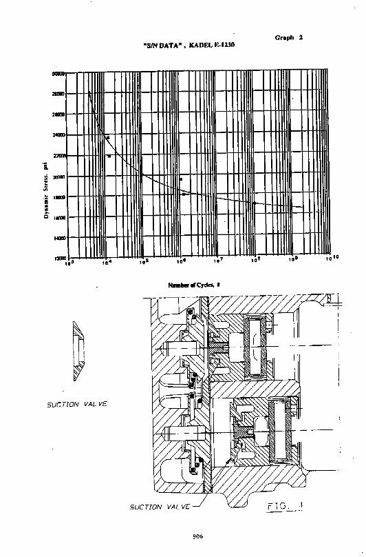
"SIN DATA"; KADEL E-1230 Graph 2
-2l1lll
2IUII
241CUJ
K 221 .~
200111 1"-
t-::--..... 1-.
...... ,.....,
IDII
SUCTION VALVE
SUCTION VALVE ~--:'
906
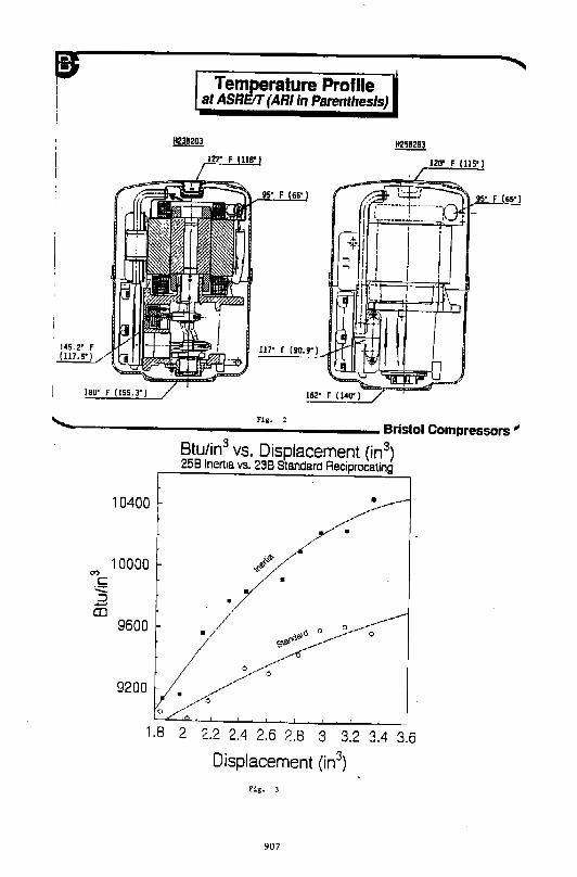
tB Temperature Profile M at ASRE!!T (ARlin Parenthesis)
I I
Fig. 2 -.....-----------------Bristol Compressors"
10400
10000
9600
9200
Btu/in3 vs. Displacement (in3)
258 lnen•a vs. 238 Standard Reciprocating
•
•
• •
0 • 0
0 0
1.8 2 2.2 2.4 2.6 2.8 3 3.2 3.4 3.6
Displacement (in3)
fig. J
907
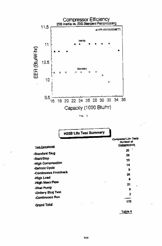
-._ J::
I
~ ::J ......
CD -rr: w w
Co~pressor Efficiency
11.5 258 lnert•a vs. 238 Standard Reciprocating
al .O.FII (45/130/65195'F)
Inertia
11 • • • • • •
• • • •
10.5 Standard
0 0 0 0 0 0 0
0
10 0-
9.5 .___._....._.._--'--o~........!.-.........J...--'---'__,_l.......;_.J.............J.........-
16 18 20 22 24 26 28 30 32 34 36
Capacity (1 000 Btu/hr)
Ftg. 4
H258 Life Test Summary )
compltlted Life Tests Number of
Ill$! Cpmp(eted Comoressofl!
·Standard Slug 26
·Start/Stop 38
·High Compression 19
•Defrost Cycle 14
.COntinuous Frostback 9
-High Load 26
·High Mass Flow 6
•Heat Pump 21
•Unitary Slug Test 9
·Continuous Run 2
Grand Total 110
Table4
908