Embed Size (px)
Citation preview
Disc Grinding Guide
Jowitt & Rodgers Co.9400 State Rd.
Philadelphia, PA 19114
215-824-0400
1
CONTENTS I. INTRODUCTION - GENERAL DISC GRINDING OVERVIEW ..............................................................................2
A. UNIQUE CHARACTERISTICS OF DISC GRINDING..................................................................................2 B. FEED MECHANISMS......................................................................................................................................2
II. ROTARY FEED DOUBLE DISC GRINDING..............................................................................................................3
A. GENERAL CONSIDERATIONS......................................................................................................................3 B. SPECIAL ABRASIVES SELECTION CONSIDERATIONS FOR ROTARY FEED MACHINES............4 C. TYPICAL ROTARY SET-UPS.........................................................................................................................5 D. ALIGNMENT AND SET-UP PROCEDURES ................................................................................................5
III. THROUGH FEED DISC GRINDERS.............................................................................................................................6
A. GENERAL CONSIDERATIONS......................................................................................................................6 B. MISCELLANEOUS INFORMATION ON THROUGH FEED MACHINES...............................................8 C. ALIGNMENT AND SET-UP PROCEDURES ................................................................................................8
IV. ABRASIVES....................................................................................................................................................................11
A. GRAIN...............................................................................................................................................................11 B. GRITS ...............................................................................................................................................................13 C. BOND TYPES...................................................................................................................................................13
V. DIAGNOSTICS...............................................................................................................................................................15
A. OVERVIEW ......................................................................................................................................................15 B. ORDER OF DIAGNOSTICS...........................................................................................................................15 C. PARALLELISM...............................................................................................................................................16 D. FLATNESS.......................................................................................................................................................18 E. FINISH ..............................................................................................................................................................19 F. SCRATCHES....................................................................................................................................................21 G. BURN................................................................................................................................................................21 H. BLEMISHES AND MARKS ..........................................................................................................................23 I. THICKNESS.....................................................................................................................................................24 J. ANALYZING WHEEL SHAPES ...................................................................................................................27
IV. GLOSSARY OF TERMS ...............................................................................................................................................28
2
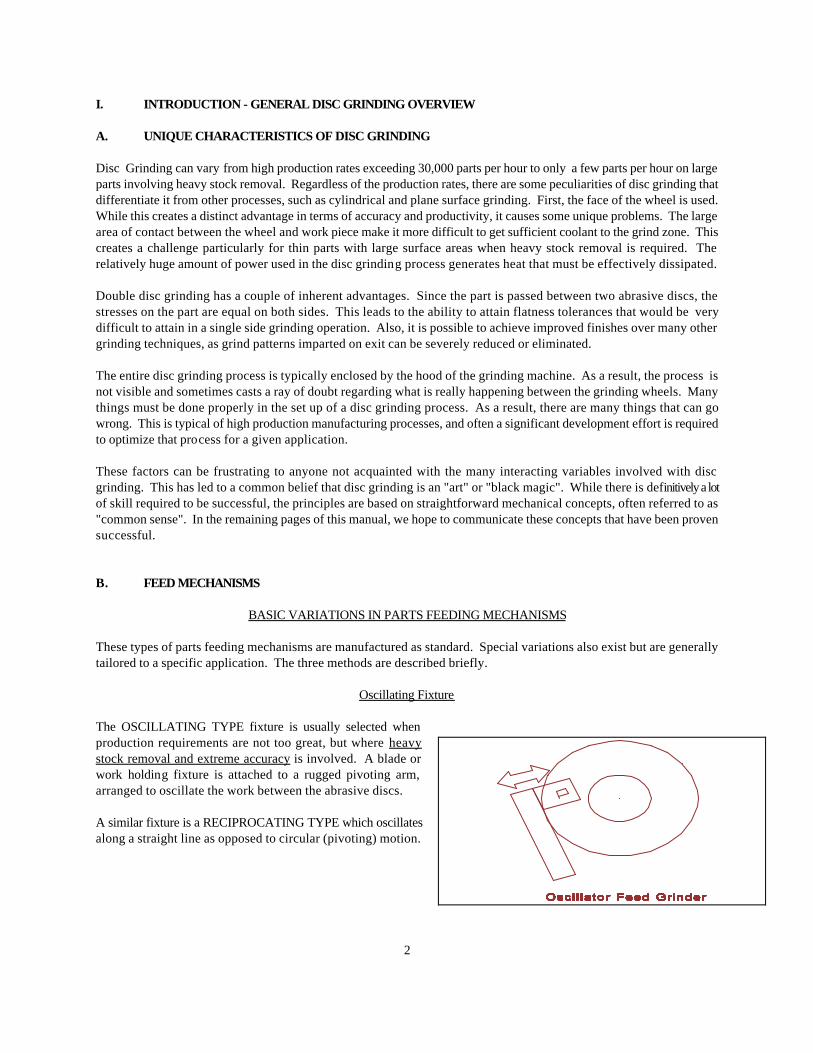
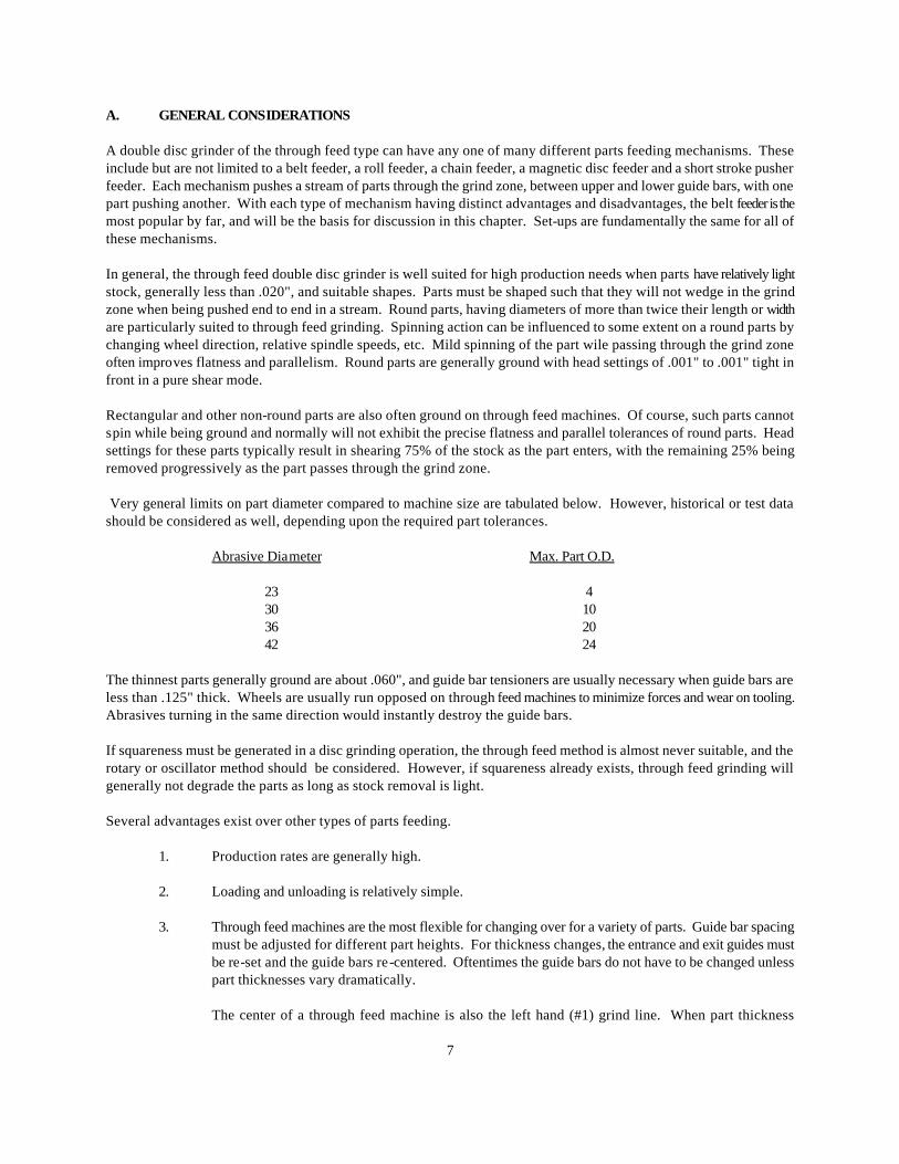
I. INTRODUCTION - GENERAL DISC GRINDING OVERVIEW A. UNIQUE CHARACTERISTICS OF DISC GRINDING Disc Grinding can vary from high production rates exceeding 30,000 parts per hour to only a few parts per hour on large parts involving heavy stock removal. Regardless of the production rates, there are some peculiarities of disc grinding that differentiate it from other processes, such as cylindrical and plane surface grinding. First, the face of the wheel is used. While this creates a distinct advantage in terms of accuracy and productivity, it causes some unique problems. The large area of contact between the wheel and work piece make it more difficult to get sufficient coolant to the grind zone. This creates a challenge particularly for thin parts with large surface areas when heavy stock removal is required. The relatively huge amount of power used in the disc grinding process generates heat that must be effectively dissipated. Double disc grinding has a couple of inherent advantages. Since the part is passed between two abrasive discs, the stresses on the part are equal on both sides. This leads to the ability to attain flatness tolerances that would be very difficult to attain in a single side grinding operation. Also, it is possible to achieve improved finishes over many other grinding techniques, as grind patterns imparted on exit can be severely reduced or eliminated. The entire disc grinding process is typically enclosed by the hood of the grinding machine. As a result, the process is not visible and sometimes casts a ray of doubt regarding what is really happening between the grinding wheels. Many things must be done properly in the set up of a disc grinding process. As a result, there are many things that can go wrong. This is typical of high production manufacturing processes, and often a significant development effort is required to optimize that process for a given application. These factors can be frustrating to anyone not acquainted with the many interacting variables involved with disc grinding. This has led to a common belief that disc grinding is an "art" or "black magic". While there is definitively a lot of skill required to be successful, the principles are based on straightforward mechanical concepts, often referred to as "common sense". In the remaining pages of this manual, we hope to communicate these concepts that have been proven successful. B. FEED MECHANISMS BASIC VARIATIONS IN PARTS FEEDING MECHANISMS These types of parts feeding mechanisms are manufactured as standard. Special variations also exist but are generally tailored to a specific application. The three methods are described briefly. Oscillating Fixture The OSCILLATING TYPE fixture is usually selected when production requirements are not too great, but where heavy stock removal and extreme accuracy is involved. A blade or work holding fixture is attached to a rugged pivoting arm, arranged to oscillate the work between the abrasive discs. A similar fixture is a RECIPROCATING TYPE which oscillates along a straight line as opposed to circular (pivoting) motion.
3
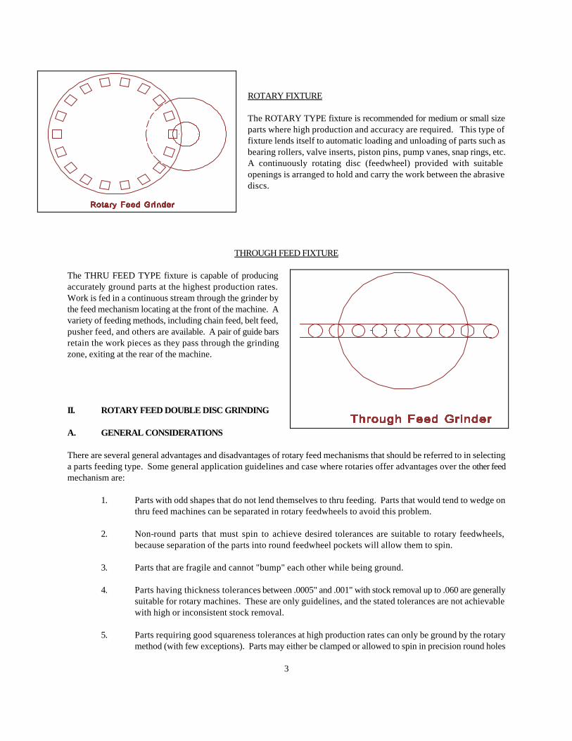
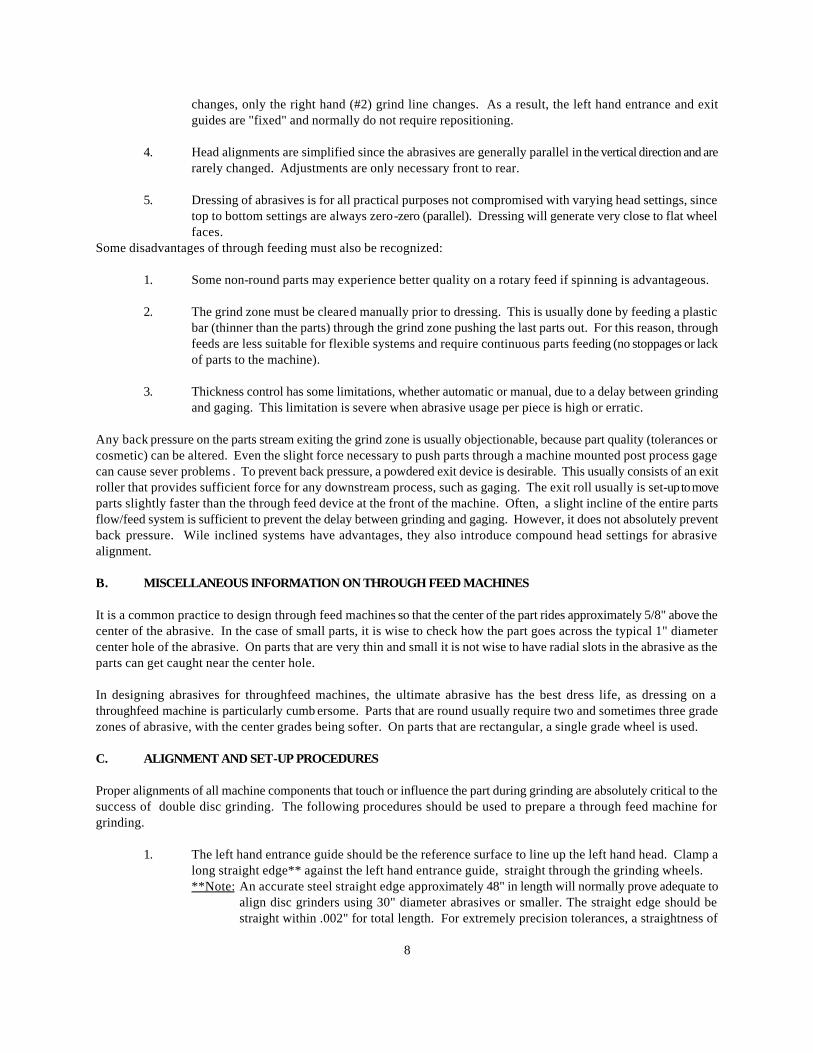
ROTARY FIXTURE The ROTARY TYPE fixture is recommended for medium or small size parts where high production and accuracy are required. This type of fixture lends itself to automatic loading and unloading of parts such as bearing rollers, valve inserts, piston pins, pump vanes, snap rings, etc. A continuously rotating disc (feedwheel) provided with suitable openings is arranged to hold and carry the work between the abrasive discs.
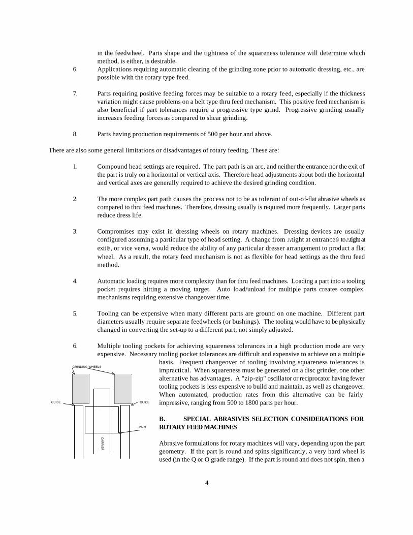
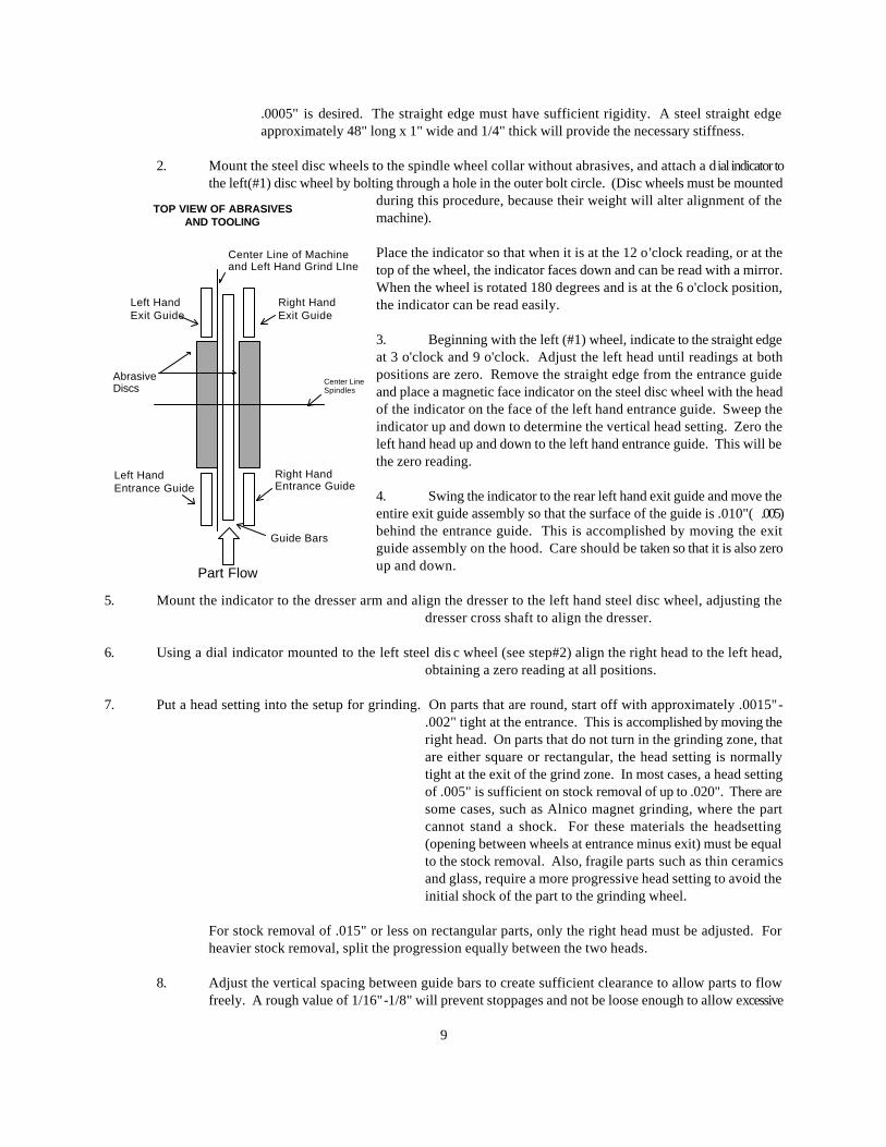
THROUGH FEED FIXTURE The THRU FEED TYPE fixture is capable of producing accurately ground parts at the highest production rates. Work is fed in a continuous stream through the grinder by the feed mechanism locating at the front of the machine. A variety of feeding methods, including chain feed, belt feed, pusher feed, and others are available. A pair of guide bars retain the work pieces as they pass through the grinding zone, exiting at the rear of the machine. II. ROTARY FEED DOUBLE DISC GRINDING A. GENERAL CONSIDERATIONS There are several general advantages and disadvantages of rotary feed mechanisms that should be referred to in selecting a parts feeding type. Some general application guidelines and case where rotaries offer advantages over the other feed mechanism are:
1. Parts with odd shapes that do not lend themselves to thru feeding. Parts that would tend to wedge on thru feed machines can be separated in rotary feedwheels to avoid this problem.
2. Non-round parts that must spin to achieve desired tolerances are suitable to rotary feedwheels,
because separation of the parts into round feedwheel pockets will allow them to spin.
3. Parts that are fragile and cannot "bump" each other while being ground.
4. Parts having thickness tolerances between .0005" and .001" with stock removal up to .060 are generally suitable for rotary machines. These are only guidelines, and the stated tolerances are not achievable with high or inconsistent stock removal.
5. Parts requiring good squareness tolerances at high production rates can only be ground by the rotary
method (with few exceptions). Parts may either be clamped or allowed to spin in precision round holes
4
in the feedwheel. Parts shape and the tightness of the squareness tolerance will determine which method, is either, is desirable.
6. Applications requiring automatic clearing of the grinding zone prior to automatic dressing, etc., are possible with the rotary type feed.
7. Parts requiring positive feeding forces may be suitable to a rotary feed, especially if the thickness
variation might cause problems on a belt type thru feed mechanism. This positive feed mechanism is also beneficial if part tolerances require a progressive type grind. Progressive grinding usually increases feeding forces as compared to shear grinding.
8. Parts having production requirements of 500 per hour and above.
There are also some general limitations or disadvantages of rotary feeding. These are:
1. Compound head settings are required. The part path is an arc, and neither the entrance nor the exit of the part is truly on a horizontal or vertical axis. Therefore head adjustments about both the horizontal and vertical axes are generally required to achieve the desired grinding condition.
2. The more complex part path causes the process not to be as tolerant of out-of-flat abrasive wheels as
compared to thru feed machines. Therefore, dressing usually is required more frequently. Larger parts reduce dress life.
3. Compromises may exist in dressing wheels on rotary machines. Dressing devices are usually
configured assuming a particular type of head setting. A change from Atight at entrance@ to Atight at exit@, or vice versa, would reduce the ability of any particular dresser arrangement to product a flat wheel. As a result, the rotary feed mechanism is not as flexible for head settings as the thru feed method.
4. Automatic loading requires more complexity than for thru feed machines. Loading a part into a tooling
pocket requires hitting a moving target. Auto load/unload for multiple parts creates complex mechanisms requiring extensive changeover time.
5. Tooling can be expensive when many different parts are ground on one machine. Different part
diameters usually require separate feedwheels (or bushings). The tooling would have to be physically changed in converting the set-up to a different part, not simply adjusted.
6. Multiple tooling pockets for achieving squareness tolerances in a high production mode are very
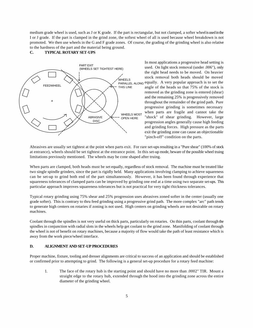
expensive. Necessary tooling pocket tolerances are difficult and expensive to achieve on a multiple basis. Frequent changeover of tooling involving squareness tolerances is impractical. When squareness must be generated on a disc grinder, one other alternative has advantages. A "zip-zip" oscillator or reciprocator having fewer tooling pockets is less expensive to build and maintain, as well as changeover. When automated, production rates from this alternative can be fairly impressive, ranging from 500 to 1800 parts per hour. B. SPECIAL ABRASIVES SELECTION CONSIDERATIONS FOR ROTARY FEED MACHINES Abrasive formulations for rotary machines will vary, depending upon the part geometry. If the part is round and spins significantly, a very hard wheel is used (in the Q or O grade range). If the part is round and does not spin, then a
GRINDING WHEELS
PART
GUIDEGUIDE
CA
RR
IER
5
medium grade wheel is used, such as J or K grade. If the part is rectangular, but not clamped, a softer wheel is used in the I or J grade. If the part is clamped in the grind zone, the softest wheel of all is used because wheel breakdown is not promoted. We then use wheels in the G and F grade zones. Of course, the grading of the grinding wheel is also relative to the hardness of the part and the material being ground. C. TYPICAL ROTARY SET-UPS
In most applications a progressive head setting is used. On light stock removal (under .006"), only the right head needs to be moved. On heavier stock removal both heads should be moved equally. A very popular approach is to set the angle of the heads so that 75% of the stock is removed as the grinding zone is entered (shear) and the remaining 25% is progressively removed throughout the remainder of the grind path. Pure progressive grinding is sometimes necessary when parts are fragile and cannot take the "shock" of shear grinding. However, large progression angles generally cause high feeding and grinding forces. High pressure as the parts exit the grinding zone can cause an objectionable "pinch-off" condition on the parts.
Abrasives are usually set tightest at the point when parts exit. For rare set-ups resulting in a "Pure shear" (100% of stock at entrance), wheels should be set tightest at the entrance point. In this set-up mode, beware of the possible wheel truing limitations previously mentioned. The wheels may be cone shaped after truing. When parts are clamped, both heads must be set equally, regardless of stock removal. The machine must be treated like two single spindle grinders, since the part is rigidly held. Many applications involving clamping to achieve squareness can be set-up to grind both end of the part simultaneously. However, it has been found through experience that squareness tolerances of clamped parts can be improved by grinding one end at a time using two separate set-ups. This particular approach improves squareness tolerances but is not practical for very tight thickness tolerances. Typical rotary grinding using 75% shear and 25% progression uses abrasives zoned softer in the center (usually one grade softer). This is contrary to thru feed grinding using a progressive grind path. The more complex "arc" path tends to generate high centers on rotaries if zoning is not used. High centers on grinding wheels are not desirable on rotary machines. Coolant through the spindles is not very useful on thick parts, particularly on rotaries. On thin parts, coolant through the spindles in conjunction with radial slots in the wheels help get coolant to the grind zone. Manifolding of coolant through the wheel is not of benefit on rotary machines, because a majority of flow would take the path of least resistance which is away from the work piece/wheel interface. D. ALIGNMENT AND SET-UP PROCEDURES Proper machine, fixture, tooling and dresser alignments are critical to success of an application and should be established or confirmed prior to attempting to grind. The following is a general set-up procedure for a rotary feed machine:
1. The face of the rotary hub is the starting point and should have no more than .0002" TIR. Mount a straight edge to the rotary hub, extended through the hood into the grinding zone across the entire diameter of the grinding wheel.
PART EXIT (WHEELS SET TIGHTEST HERE)
WHEELSPARALLEL ALONGTHIS LINE
WHEELS MOSTOPEN HERE
FEEDWHEEL
ABRASIVE DISC
6
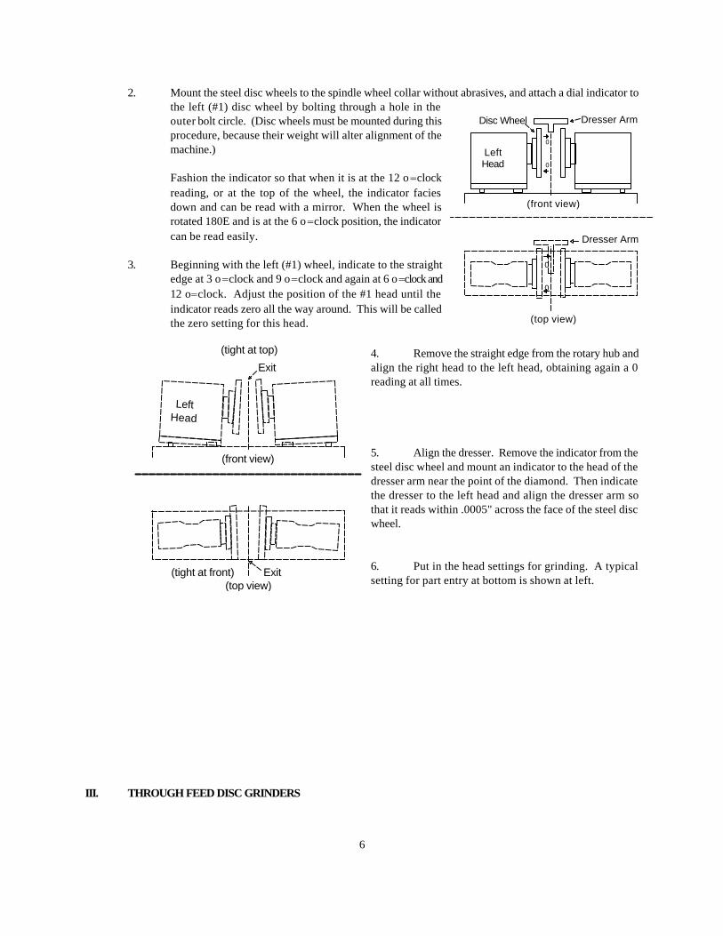
2. Mount the steel disc wheels to the spindle wheel collar without abrasives, and attach a dial indicator to the left (#1) disc wheel by bolting through a hole in the outer bolt circle. (Disc wheels must be mounted during this procedure, because their weight will alter alignment of the machine.)
Fashion the indicator so that when it is at the 12 o=clock reading, or at the top of the wheel, the indicator facies down and can be read with a mirror. When the wheel is rotated 180Ε and is at the 6 o=clock position, the indicator can be read easily.
3. Beginning with the left (#1) wheel, indicate to the straight
edge at 3 o=clock and 9 o=clock and again at 6 o=clock and 12 o=clock. Adjust the position of the #1 head until the indicator reads zero all the way around. This will be called the zero setting for this head.
4. Remove the straight edge from the rotary hub and align the right head to the left head, obtaining again a 0 reading at all times.
5. Align the dresser. Remove the indicator from the steel disc wheel and mount an indicator to the head of the dresser arm near the point of the diamond. Then indicate the dresser to the left head and align the dresser arm so that it reads within .0005" across the face of the steel disc wheel. 6. Put in the head settings for grinding. A typical setting for part entry at bottom is shown at left.
III. THROUGH FEED DISC GRINDERS
0
0
Disc Wheel Dresser Arm
LeftHead
(front view)
0
0
(top view)
Dresser Arm
LeftHead
(front view)
(top view)
Exit
(tight at top)
Exit(tight at front)
7
A. GENERAL CONSIDERATIONS A double disc grinder of the through feed type can have any one of many different parts feeding mechanisms. These include but are not limited to a belt feeder, a roll feeder, a chain feeder, a magnetic disc feeder and a short stroke pusher feeder. Each mechanism pushes a stream of parts through the grind zone, between upper and lower guide bars, with one part pushing another. With each type of mechanism having distinct advantages and disadvantages, the belt feeder is the most popular by far, and will be the basis for discussion in this chapter. Set-ups are fundamentally the same for all of these mechanisms. In general, the through feed double disc grinder is well suited for high production needs when parts have relatively light stock, generally less than .020", and suitable shapes. Parts must be shaped such that they will not wedge in the grind zone when being pushed end to end in a stream. Round parts, having diameters of more than twice their length or width are particularly suited to through feed grinding. Spinning action can be influenced to some extent on a round parts by changing wheel direction, relative spindle speeds, etc. Mild spinning of the part wile passing through the grind zone often improves flatness and parallelism. Round parts are generally ground with head settings of .001" to .001" tight in front in a pure shear mode. Rectangular and other non-round parts are also often ground on through feed machines. Of course, such parts cannot spin while being ground and normally will not exhibit the precise flatness and parallel tolerances of round parts. Head settings for these parts typically result in shearing 75% of the stock as the part enters, with the remaining 25% being removed progressively as the part passes through the grind zone. Very general limits on part diameter compared to machine size are tabulated below. However, historical or test data should be considered as well, depending upon the required part tolerances.
Abrasive Diameter Max. Part O.D.
23 4 30 10 36 20 42 24
The thinnest parts generally ground are about .060", and guide bar tensioners are usually necessary when guide bars are less than .125" thick. Wheels are usually run opposed on through feed machines to minimize forces and wear on tooling. Abrasives turning in the same direction would instantly destroy the guide bars. If squareness must be generated in a disc grinding operation, the through feed method is almost never suitable, and the rotary or oscillator method should be considered. However, if squareness already exists, through feed grinding will generally not degrade the parts as long as stock removal is light. Several advantages exist over other types of parts feeding.
1. Production rates are generally high.
2. Loading and unloading is relatively simple.
3. Through feed machines are the most flexible for changing over for a variety of parts. Guide bar spacing must be adjusted for different part heights. For thickness changes, the entrance and exit guides must be re-set and the guide bars re-centered. Oftentimes the guide bars do not have to be changed unless part thicknesses vary dramatically.
The center of a through feed machine is also the left hand (#1) grind line. When part thickness
8
changes, only the right hand (#2) grind line changes. As a result, the left hand entrance and exit guides are "fixed" and normally do not require repositioning.
4. Head alignments are simplified since the abrasives are generally parallel in the vertical direction and are
rarely changed. Adjustments are only necessary front to rear.
5. Dressing of abrasives is for all practical purposes not compromised with varying head settings, since top to bottom settings are always zero-zero (parallel). Dressing will generate very close to flat wheel faces.
Some disadvantages of through feeding must also be recognized:
1. Some non-round parts may experience better quality on a rotary feed if spinning is advantageous.
2. The grind zone must be cleared manually prior to dressing. This is usually done by feeding a plastic bar (thinner than the parts) through the grind zone pushing the last parts out. For this reason, through feeds are less suitable for flexible systems and require continuous parts feeding (no stoppages or lack of parts to the machine).
3. Thickness control has some limitations, whether automatic or manual, due to a delay between grinding
and gaging. This limitation is severe when abrasive usage per piece is high or erratic. Any back pressure on the parts stream exiting the grind zone is usually objectionable, because part quality (tolerances or cosmetic) can be altered. Even the slight force necessary to push parts through a machine mounted post process gage can cause sever problems . To prevent back pressure, a powdered exit device is desirable. This usually consists of an exit roller that provides sufficient force for any downstream process, such as gaging. The exit roll usually is set-up to move parts slightly faster than the through feed device at the front of the machine. Often, a slight incline of the entire parts flow/feed system is sufficient to prevent the delay between grinding and gaging. However, it does not absolutely prevent back pressure. Wile inclined systems have advantages, they also introduce compound head settings for abrasive alignment. B. MISCELLANEOUS INFORMATION ON THROUGH FEED MACHINES It is a common practice to design through feed machines so that the center of the part rides approximately 5/8" above the center of the abrasive. In the case of small parts, it is wise to check how the part goes across the typical 1" diameter center hole of the abrasive. On parts that are very thin and small it is not wise to have radial slots in the abrasive as the parts can get caught near the center hole. In designing abrasives for throughfeed machines, the ultimate abrasive has the best dress life, as dressing on a throughfeed machine is particularly cumb ersome. Parts that are round usually require two and sometimes three grade zones of abrasive, with the center grades being softer. On parts that are rectangular, a single grade wheel is used. C. ALIGNMENT AND SET-UP PROCEDURES Proper alignments of all machine components that touch or influence the part during grinding are absolutely critical to the success of double disc grinding. The following procedures should be used to prepare a through feed machine for grinding.
1. The left hand entrance guide should be the reference surface to line up the left hand head. Clamp a long straight edge** against the left hand entrance guide, straight through the grinding wheels. **Note: An accurate steel straight edge approximately 48" in length will normally prove adequate to
align disc grinders using 30" diameter abrasives or smaller. The straight edge should be straight within .002" for total length. For extremely precision tolerances, a straightness of
9
.0005" is desired. The straight edge must have sufficient rigidity. A steel straight edge approximately 48" long x 1" wide and 1/4" thick will provide the necessary stiffness.
2. Mount the steel disc wheels to the spindle wheel collar without abrasives, and attach a dial indicator to
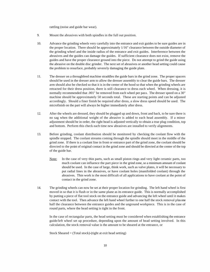
the left(#1) disc wheel by bolting through a hole in the outer bolt circle. (Disc wheels must be mounted during this procedure, because their weight will alter alignment of the machine). Place the indicator so that when it is at the 12 o'clock reading, or at the top of the wheel, the indicator faces down and can be read with a mirror. When the wheel is rotated 180 degrees and is at the 6 o'clock position, the indicator can be read easily. 3. Beginning with the left (#1) wheel, indicate to the straight edge at 3 o'clock and 9 o'clock. Adjust the left head until readings at both positions are zero. Remove the straight edge from the entrance guide and place a magnetic face indicator on the steel disc wheel with the head of the indicator on the face of the left hand entrance guide. Sweep the indicator up and down to determine the vertical head setting. Zero the left hand head up and down to the left hand entrance guide. This will be the zero reading. 4. Swing the indicator to the rear left hand exit guide and move the entire exit guide assembly so that the surface of the guide is .010"(∀.005) behind the entrance guide. This is accomplished by moving the exit guide assembly on the hood. Care should be taken so that it is also zero up and down.
5. Mount the indicator to the dresser arm and align the dresser to the left hand steel disc wheel, adjusting the dresser cross shaft to align the dresser.
6. Using a dial indicator mounted to the left steel dis c wheel (see step#2) align the right head to the left head,
obtaining a zero reading at all positions. 7. Put a head setting into the setup for grinding. On parts that are round, start off with approximately .0015"-
.002" tight at the entrance. This is accomplished by moving the right head. On parts that do not turn in the grinding zone, that are either square or rectangular, the head setting is normally tight at the exit of the grind zone. In most cases, a head setting of .005" is sufficient on stock removal of up to .020". There are some cases, such as Alnico magnet grinding, where the part cannot stand a shock. For these materials the headsetting (opening between wheels at entrance minus exit) must be equal to the stock removal. Also, fragile parts such as thin ceramics and glass, require a more progressive head setting to avoid the initial shock of the part to the grinding wheel.
For stock removal of .015" or less on rectangular parts, only the right head must be adjusted. For heavier stock removal, split the progression equally between the two heads.
8. Adjust the vertical spacing between guide bars to create sufficient clearance to allow parts to flow
freely. A rough value of 1/16"-1/8" will prevent stoppages and not be loose enough to allow excessive
Center LineSpindles
Right Hand Entrance Guide
Left HandEntrance Guide
Part Flow
Guide Bars
Right HandExit Guide
Left Hand Exit Guide
Abrasive Discs
Center Line of Machineand Left Hand Grind LIne
TOP VIEW OF ABRASIVESAND TOOLING
10
rattling (noise and guide bar wear).
9. Mount the abrasives with both spindles in the full out position.
10. Advance the grinding wheels very carefully into the entrance and exit guides to be sure guides are in the proper location. There should be approximately 1/16" clearance between the outside diameter of the grinding wheel and the inside radius of the entrance and exit guides. Interference between the abrasives and the guides can damage the guides. If sufficient clearance does not exist, remove the guides and have the proper clearance ground into the piece. Do not attempt to grind the guide using the abrasive on the double disc grinder. The next set of abrasives or another head setting could cause the problem to resurface, probably severely damaging the guide plate.
11. The dresser on a throughfeed machine straddles the guide bars in the grind zone. The proper spacers
should be used in the dresser arm to allow the dresser assembly to clear the guide bars. The dresser arm should also be checked so that it is in the center of the hood so that when the grinding wheels are retracted for their dress position, there is still clearance to dress each wheel. When dressing, it is normally recommended that .001" be removed from each wheel per pass. The dresser speed on a 30" machine should be approximately 50 seconds total. These are starting points and can be adjusted accordingly. Should a finer finish be required after dress, a slow dress speed should be used. The microfinish on the part will always be higher immediately after dress.
12. After the wheels are dressed, they should be plugged up and down, front and back, to be sure there is
no sag when the additional weight of the abrasive is added to each head assembly. If a minor adjustment should be in order, the right head is adjusted vertically to obtain a true plug condition, top and bottom. Perform this check each time new abrasives are installed to verify alignments.
13. Before grinding, coolant distribution should be monitored by checking the coolant flow with the
spindle stopped. The coolant streams coming through the spindle should meet in the middle of the grind zone. If there is a coolant line in front or entrance part of the grind zone, the coolant should be directed to the point of original contact in the grind zone and should be directed at the center of the top of the guide bar.
Note: In the case of very thin parts, such as small piston rings and very light ceramic parts, too
much coolant can influence the part piece in the grind zone, so a minimum amount of coolant should be used. In the case of large, think work, such as valve plates, it will be necessary to put radial lines in the abrasives, or have coolant holes (manifolded coolant) through the abrasives. Thin work is the most difficult of all applications to have coolant at the point of contact in the grind zone.
14. The grinding wheels can now be set at their proper location for grinding. The left hand wheel is first
moved in so that it is flush or in the same plane as its entrance guide. This is normally accomplished by putting a piece of flat tool stock on the entrance guide and advancing the left wheel until it makes contact with the tool. Then advance the left hand wheel further to one half the stock removal plus one half the clearance between the entrance guides and the unground workpiece. This is in the case of round parts, where the head setting is tight in the front.
In the case of rectangular parts, the head setting must be considered when establishing the entrance
guide/left wheel set up procedure, depending upon the amount of head setting involved. In this calculation, the stock removal value is the amount to be sheared at the entrance, or
Stock Sheared = (Total stock)-(tight at exit head setting)
11
Bring the right hand entrance guide in to approximately .010" from the thickest part on rough grinding operations, considering warpage, flashings, and various irregularities of a rough grind. On semi-finish and finish work, the right hand entrance guide should be brought to within .004" for a better setup.
The objective of entrance guide clearances and wheel locations is to present equal stock to both grinding wheels.
15. The right hand exit guide should be set sufficiently away from the grind zone so that it does not
interfere with the part coming out of the grind zone, but merely holds it on the exit guide bars. The exit guides should never be used to steer the parts out of the grind zone. The grinding wheels themselves must be the only guiding influence as the part exits the grinding zone. It is recommended that the exit guide be set .010"(∀.005") behind the entrance guide.
Note: On throughfeed machines, particularly for long parts, the exit area of the grind zone must be
kept clear of any part interference, such as coolant brushes, tight exit guides or gage fixturing that would slow up the parts, as back pressure into the grind zone will cause swipe marks on the parts. In the case of machine mounted post process gages, the gage should be of such a design that there is no back pressure (such as double opposed air), or the machine should include a powered exit drive assembly to speed up the parts through the gage.
16. The right hand grinding wheel is now ready to be moved into place. A work piece is put between the
grinding wheels near the entrance on a round part and near the exit on a square part. The right wheel is brought in so that the wheel spacing is close to the finished thickness of the part. The part is then pushed through the grinding zone with the grinding wheels running, hood closed, with a stick thinner than the work piece. Measure the thickness and adjust the right wheel only. Repeat this test until proper thickness is achieved.
17. Once size is obtained, both wheels are brought in either simultaneously or alternately as the wheels
wear to maintain size. In monitoring size on a throughfeed machine, consider that the parts are usually being finished at the entrance of the grind zone and do not over react to infeeding. Wait for parts to clear through the grind zone after an infeed. It is of utmost importance on a throughfeed machine, that there is constant feeding of the parts through the grind zone. Should the flow of parts stop,either through a jam in the front, exit, or lack of parts, those parts in the grinding zone should not be considered a true representation of the quality of the grind.
In selecting an increment of feed, it is suggested that not more than 50% of the size tolerance be used as an increment. For example, if the thickness tolerance is .0005", the maximum infeed increment that should be considered is .00025".
IV. ABRASIVES A. GRAIN - The abrasive particles used in grinding are called grain. The materials used as grain have two
important properties. They are very hard and they have sharp edges. In order to be effective, the grain must be harder than the material being ground and must also be able to stay sharp during the grinding process. The friability of the grain therefore also is important. As the grain is used, its friability determines how quickly it fractures and forms new cutting edges. The more friable the grain, the more quickly it fractures and the sharper it stays and the more aggressively it will cut.
There are several materials that are widely used as abrasive grains:
12
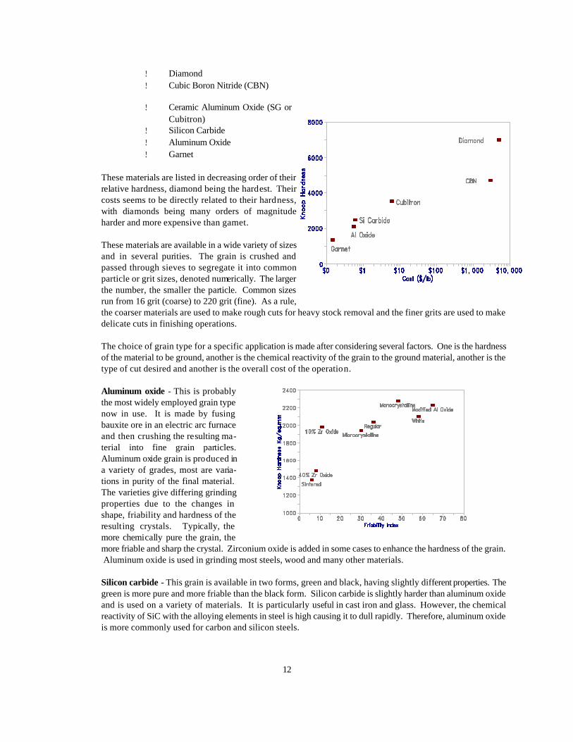
! Diamond ! Cubic Boron Nitride (CBN)
! Ceramic Aluminum Oxide (SG or Cubitron)
! Silicon Carbide ! Aluminum Oxide ! Garnet
These materials are listed in decreasing order of their relative hardness, diamond being the hardest. Their costs seems to be directly related to their hardness, with diamonds being many orders of magnitude harder and more expensive than garnet.
These materials are available in a wide variety of sizes and in several purities. The grain is crushed and passed through sieves to segregate it into common particle or grit sizes, denoted numerically. The larger the number, the smaller the particle. Common sizes run from 16 grit (coarse) to 220 grit (fine). As a rule, the coarser materials are used to make rough cuts for heavy stock removal and the finer grits are used to make delicate cuts in finishing operations.
The choice of grain type for a specific application is made after considering several factors. One is the hardness of the material to be ground, another is the chemical reactivity of the grain to the ground material, another is the type of cut desired and another is the overall cost of the operation.
Aluminum oxide - This is probably the most widely employed grain type now in use. It is made by fusing bauxite ore in an electric arc furnace and then crushing the resulting ma-terial into fine grain particles. Aluminum oxide grain is produced in a variety of grades, most are varia-tions in purity of the final material. The varieties give differing grinding properties due to the changes in shape, friability and hardness of the resulting crystals. Typically, the more chemically pure the grain, the more friable and sharp the crystal. Zirconium oxide is added in some cases to enhance the hardness of the grain. Aluminum oxide is used in grinding most steels, wood and many other materials.
Silicon carbide - This grain is available in two forms, green and black, having slightly different properties. The
green is more pure and more friable than the black form. Silicon carbide is slightly harder than aluminum oxide and is used on a variety of materials. It is particularly useful in cast iron and glass. However, the chemical reactivity of SiC with the alloying elements in steel is high causing it to dull rapidly. Therefore, aluminum oxide is more commonly used for carbon and silicon steels.
13
Ceramic aluminum oxide - A relatively new material, it is available as SG grain from Norton and as Cubitron from 3M. This material is a non-fused, polycrystalline ceramic aluminum oxide of high purity. The material is a 'grown', solid crystal with a controlled shape. It is very hard and sharp but not very brittle. However, it is able to keep its sharp edge much longer than conventional aluminum oxide. The grain has proven to be very useful against hard steel alloys, such as tool steels.
CBN - Cubic boron nitride grain is in a class (along with diamond) known as super-abrasives. CBN is a very hard synthetic material produced under extreme temperature and pressure. It can withstand temperatures > 2500ΕF, where as diamond oxidizes (burns) at only 1600ΕF. This property makes CBN a potentially useful material for grinding steel. The limitation is its very high cost and its need for extremely rigid grinding equipment.
Diamond - Available in two forms, natural and man-made, this is the hardest material known to man. Diamond is a very commo nly used grain, despite its very high cost, for a wide variety of applications. Though not useful in grinding most steels, it is the abrasive of choice for glass and ceramics. It is also used to grind concrete, carbide tool steels, and polish gems.
Garnet - A natural gem like material, garnet is used principally in wood finishing. It is softer than aluminum oxide, so it is used sparingly for metal finishing.
J&R Specific Grains - We currently have eight specific types of grain available to incorporate in our products - various forms of aluminum oxide, silicon carbide and cubitron. Each of the grains behave differently and are used either alone or in combination with others to meet specific needs. Aluminum oxides
G - This is a form of brown aluminum oxide that is blocky and not exceptionally friable. Due to its shape and lack of friability, it is a hard acting grain, good for general purpose grinding of soft steels. It also is often used in combination with more friable grains to add additional life to the wheel. It is a relatively inexpensive grain.
A - This is a more friable version of G grain. It is still an inexpensive brown aluminum oxide, but
is a little sharper and more friable. It is used on slightly harder materials than G and in combination with other grains on hard steels.
W - A white aluminum oxide, this is a very aggressive grain. It is sharper, harder and more brittle
than the brown grains. This is an expensive grain that works well on hard steels such as tool steels and stainless steel. It often is used in combination with either G or A to offset the cost.
F - An even more friable form of white aluminum oxide. It is the sharpest, most aggressive of the
aluminum oxides that we have available. F is used where W is not aggressive enough, and is often used in combination with other grains to offset the cost.
Silicon Carbide
X - This is our standard silicon carbide grain. Silicon carbide is a hard, brittle grain, more so than aluminum oxide. It is most commonly used on non-steel materials, such as cast iron and aluminum. It does not work well on steel because it is chemically reactive with the carbon in steel.
C - A more pure form of silicon carbide, it is slightly more friable than X. This grain is not used a
great deal.
14
Ceramic grains
R - A ceramic coated brown aluminum oxide, this grain forms stronger bonds with our resin. It is used to make very hard wheels.
Q - Our newest grain is Cubitron made by 3M and is very similar to SG from Norton. This grain
is a polycrstalline ceramic aluminum oxide that is extremely hard, sharp and very friable. It retains its sharpness for an extensive period, giving good wheel life and improved through put. A very aggressive grain, it is used for hard steels in combination with white aluminum oxide grain.
B. GRITS - All of the grains discussed are available in a range of sizes, called grits. They are classified by the
medium sieve size that the particles pass through. A 6 grit grain is very coarse and a 600 grit grain is extremely fine. For normal metal working applications, grits from 16 to 180 are used. The coarser grits take heavy cuts and remove large amounts of material whereas the finer grits take a delicate cut and are generally used for finishing.
C. BOND TYPES - As J&R sells bonded abrasives, we are very much concerned with the material used to hold the
abrasive grain together, called bonds. The bond glues the grain particles together, holding them to do their work. At some point in the grinding process, it is beneficial for the bond to release the grain on the working surface of the grinding wheel to expose unused, sharp grain. In an optimal situation, this happens when the grain at the surface becomes dull and no longer is cutting efficiently. The amount of bond used to hold the wheel together is varied to modify when this occurs. The relative effort required to free grain particles from the wheel surface is commonly referred to as the hardness of the wheel. Wheels that release grain easily are referred to as 'soft', and wheels that require a lot of effort to free the grain are called 'hard'. Typically, harder wheels are used on softer materials, as the grain takes longer to dull, and soft wheels are used for hard materials as the grain dulls much more rapidly.
Many different materials have been and are still being used as bonds. Some of them are:
Vitrified - This is probably the most commonly used bond. It is a glass-like material that is fused
together under high temperatures. The abrasive and bonding materials are first mixed together and then pressed together in a mold under high pressure. The wheel is then fired in a kiln for as long as several days, reaching temperatures as high as 2300ΕF. Vitrified bonds are strong, though somewhat brittle. It is its brittleness that causes it to break down during the grinding process.
Resin - This is a bond type that is distinguished for its high strength, resiliency and cool cutting
characteristics. The resins used are synthetic phenol/formaldehyde polymers that set at moderate temperatures. Resin bonded abrasives are typically baked in ovens rather than fired in kilns. Resin bond's high strength makes it the bond of choice for discs and foundry wheels, and its resiliency and cool cutting properties make it useful for many surface grinding applications. It is less appropriate for crush or form grinding, however, as it has difficulty in holding sharp edges or contours on the grinding face.
Epoxy - This is a relatively new bonding material. It has similar properties to resin bonds, though with a
bit more resiliency and cool cutting properties. Its principal drawback has been the difficulty in duplicating its performance characteristics from wheel to wheel.
Magnesite - This a relatively old bonding technology that is now used mainly for dry grinding
applications. The bond is made from a mixture of magnesium oxide and magnesium chloride to form a cold setting cement. The bond, which takes many weeks to completely set, is also referred to as Oxychloride. Magnesite is not well suited for use with coolants, as it tends to mix with the coolant and
15
solidify in the coolant lines on the grinding machine. Due to its cool cutting characteris tics, it is most commonly used in dry grinding applications such as spring and some cutlery grinding.
Metallic - Metal bonds are used mostly for super-abrasive wheels. These are mixtures of various
powdered metals that are pressed to hold diamond or CBN abrasive grain.
Other - There are many other bonding materials used, though most are used sparingly or only for very special applications. These include shellac, rubber and silicate bonds, among others.
J&R Bond Varieties
Jowitt & Rodgers manufactures only resin and epoxy bonded products. Our resin is a liquid thermosetting phenol/formaldehyde resin. This resin is unique to J&R, first developed and still manufactured by Geo. Jowitt & Sons in England. A unique feature of the resin is that it is liquid at room temperature, while most other resins are powders. Being liquid offers some mixing advantages:
! better homogeneity of the grain/bond mixture ! can be hand tamped for more consistent density ! bakes quickly (overnight) ! bakes at a low temperature.
The bond itself is very stable under most grinding conditions. However, the linkage it forms with the grain is affected by high heat and pH. At high coolant temperatures and caustic pH levels, the junction between the resin and the grain breaks down over time and the wheel will act softer. This phenomena is accelerated rapidly as temperature and/or pH is increased. Care should be taken to maintain the coolant temperature to as near to room temperature as possible and the pH to 9 or lower.
We employ an additive to reduce this effect, but it does not eliminate it. If the customer can not control the coolant conditions, two steps can be taken to retard the effect. First is to remove the coolant from the wheel if it is to sit for a prolonged period, say over a weekend or removed from the machine. This can be done by 'spin drying' the wheel (running without the coolant flow on). Also, the phenomena is lesser on larger grain sizes, so spec the wheel with absolutely the largest grit possible for the job.
V. DIAGNOSTICS A. OVERVIEW - Double Disc grinding is generally a high production, highly accurate method of producing dual
flat and parallel surfaces simultaneously. While the process can be ext remely cost effective because of its speed and precision, success can only be achieved when several set-up parameters are correct. Once the proper set-up has been achieved, the correct abrasive has been installed, and everything should be ready, problems holding grinding tolerances may still exist. When problems occur, whether during initial development of the process or in the midst of production, it is beneficial to have a thorough understanding of variables that impact disc grinding. That is the objective of this chapter, i.e., to document these variables and their impact on grinding results.
Subsequent paragraphs first address how to go about developing a process in general (the order of things), followed by a discussion of each basic type of tolerance problem that may be encountered in disc grinding. Finally, a diagnostic summary table is presented which suggests possible solutions to investigate for each type of problem encountered. This table is brief but refers back to paragraphs which discuss the subject in depth.
Disc grinding is not a black art. There is no magic. There are, however, proven methods of correcting problems
16
that this chapter be studied and understood in detail. Not every problem that may show up is discussed in this chapter, but having a sound knowledge of these basics will help you reach solutions to other problems.
One last thing to note before getting into the details of diagnostics. Often there is more than one way of achieving a desired grinding result. Experienced dis c grinders do not always agree on the best solution. In this chapter, when opposing theories are known to exist, both will be described. When multiple solutions are possible these will also be pointed out.
B. ORDER OF DIAGNOSTICS
Having a logical approach to problem solving is as important as having good knowledge of disc grinding parameters. A few suggestions are in order relating to the development of an efficient problem solving process.
1. Keep accurate records. Sometimes the development of a process will require several tries and an
extended time frame. Do not rely on your memory. Write it down. During troublesome jobs, you may need to get the advice or opinion of others. It helps to have a good chronological record of what was tried and the results. Secondly, after success has been achieved you will want to document the final solution for the record. These records will be invaluable on future similar applications.
2. Change only one variable at a time. In an effort to reach a quick solution, there is sometimes a
tendency to make several changes at once. An example would be changing the abrasive specification, head setting and coolant concentration without intermediate trials. When such an approach is used, the effect of each parameter change cannot be evaluated and, as a result, valuable information is lost.
3. Grind more than a few parts. Claiming a solution after only a few parts is premature in double disc
grinding. Freshly dressed wheels usually behave differently after several parts have been ground. Also, the number of parts that can be ground prior to dressing is important to the solution. A wheel that goes out-of-flat requiring frequent dressing is probably not acceptable. The dressing frequency can only be determined by grinding a multitude of parts.
4. Generally develop the process by reaching acceptable part tolerances in the following order:
a. Get rid of blemishes and marks - These are generally caused by set-up problems and should
be dealt with first.
b. Parallelism - if parallelism is not sufficient, there is no need to attempt holding thickness (size) tolerance, especially on critical applications. Make the required machine adjustments prior to attempting to grind several parts.
c. Finish/thickness - These tolerances must be developed together. What improves one may
detract from the other. Both parameters require the grinding of several parts to allow a freshly dressed pair of wheels to stabilize.
Several other part conditions and parameters must be evaluated but do not automatically fall into a rigid pattern. Burn, flatness, scratches, squareness, etc. must be dealt with, but their logical positions in the process depend upon the application.
C. PARALLELISM
When ground parts do not exhibit desired parallelism, the following possibilities should be considered:
17
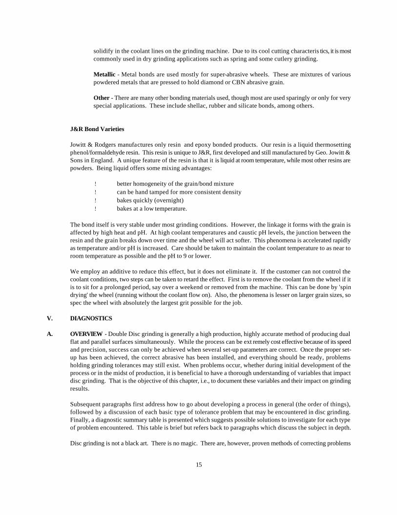
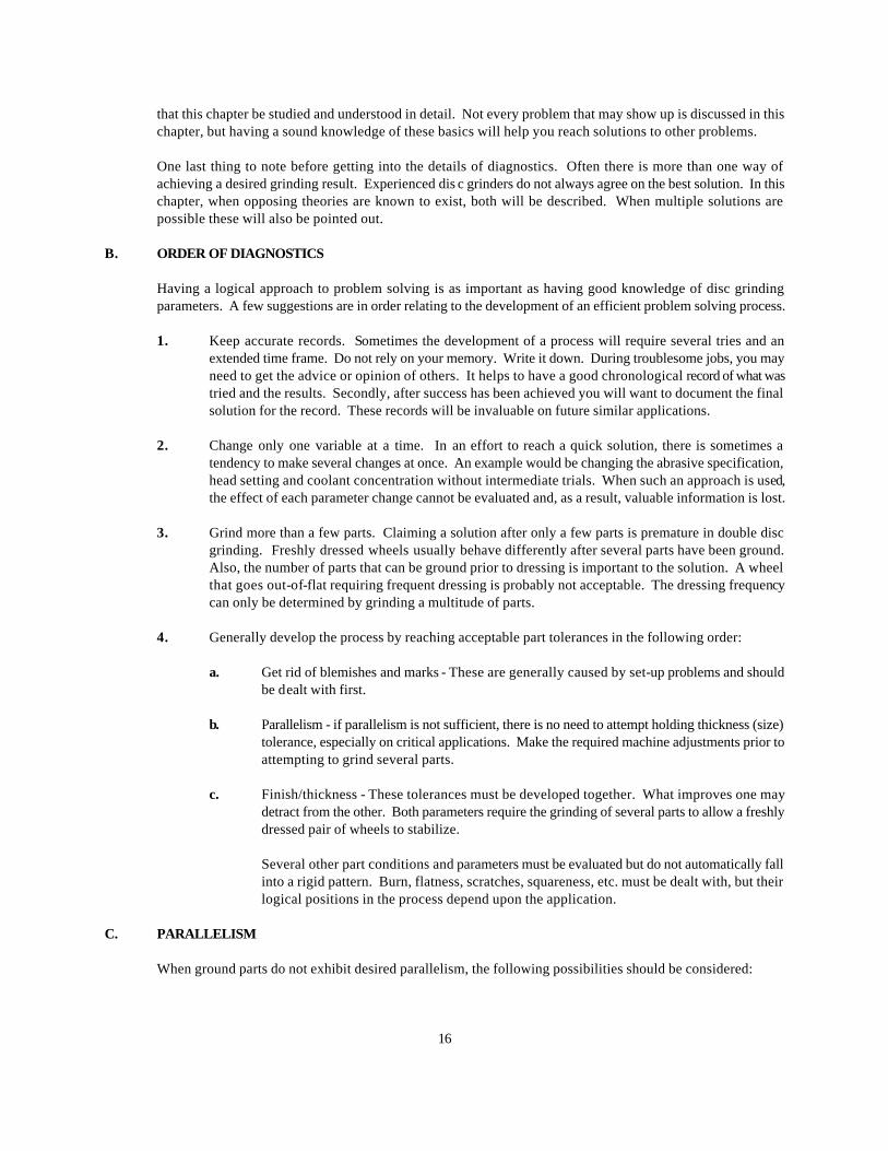
1. For a rotary feed grinder the wheels are generally tightest at point of exit from the grinding zone. Freshly
dressed wheels should be parallel along a line running from 90 Ε above the exit point to 90 Ε below the exit point. Plug the abrasive at these two points to ensure a proper setting.
Check for wheels glazing. A dull wheel can result from many things. In each case, a wheel that is not cutting freely will build up grinding pressure resulting in machine deflection.
Wheels that are dull may be glazed because they are too hard and are not breaking down uniformly, preventing the exposure of new sharp grains. A switch in abrasive specification to a softer grade or a more friable grain may be necessary to keep the wheel constantly sharp. Erratic surface finish will also indicate that the wheel is undergoing a "glazing, breaking, glazing, breaking" cycle.
Improper dressing may cause a wheel to glaze. Wheels that are dressed tight will generally remain tight. Wheels that are dressed open will generally remain that way during grinding. To open up a wheel or dress it sharper, use single point diamond or dresser cutters.1 Speeding up the dresser to create a record groove effect will also generate a more open wheel.
An effect similar to glazing would be wheel loading where grinding particles cling to the wheel or embed in the bond. This reduces chip clearance and dulls the wheel. The solution may be a softer
wheel grade or a different type of abrasive grain material. Dirty coolant that carries swarf and impurities into the grinding wheel, clogging open areas used to carry coolant and chips, is another culprit that can cause dulling action. Adequate filtration must be provided. Check the coolant concentration. It should have a pH in the range of 7-9. Thick coolant can cause loading. 3. Parts not spinning while grinding. Spinning improves parallelism. Round parts that are spinning while being ground exhibit a random cross hatched finish. Grind marks on the part that are parallel indicate that
spinning is being restricted. Spinning can be achieved by running one wheel slightly faster than the other when they are rotating opposed.
Abrasives rotating together will create the most violent spinning action of all and should be generally avoided. Noise, high tooling wear, as well as cosmetic blemishes may result from a violent spinning action.
1There are negatives associated with a single point diamonds and dresser cutters. Although they can produce
sharper wheels, their wear rate is higher, especially for cutters.
PART EXIT (WHEELS SET TIGHTEST HERE)
WHEELSPARALLEL ALONGTHIS LINE
WHEELS MOSTOPEN HERE
FEEDWHEEL
ABRASIVE DISC
18
Clearances between parts and tooling may be insufficient, restricting free spinning.
4. Abrasives out-of-flat. When abrasives reach a certain level of out-of-flatness, poor tolerances,
including parallelism, result. It signals the need to dress the wheel flat. When parallelism deteriorates over the life of a dress, it is an indication that abrasive shape is the cause.
If dressing is required too frequently, measures to keep the wheel flat, such as zoning, should be considered.
Improper set-up can also cause wheels to go out of shape prematurely. Stock removal that is not split equally between the abrasives can cause mis -shaped wheels. Proper set-up can correct this.
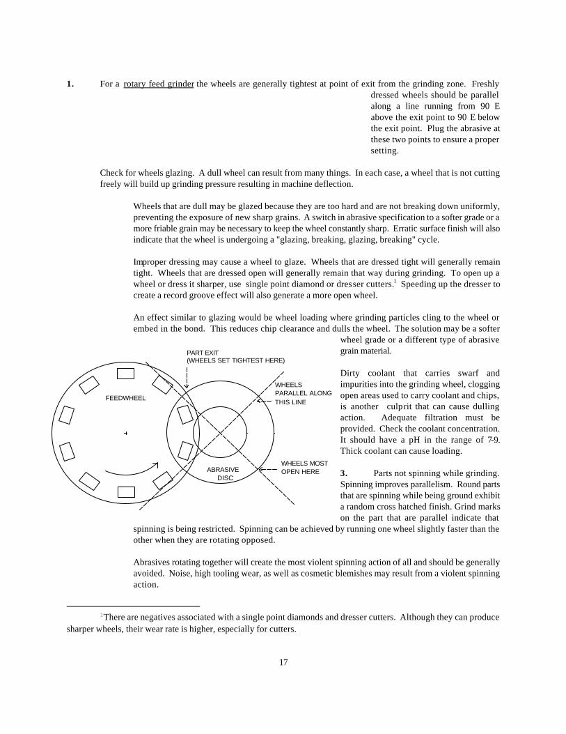
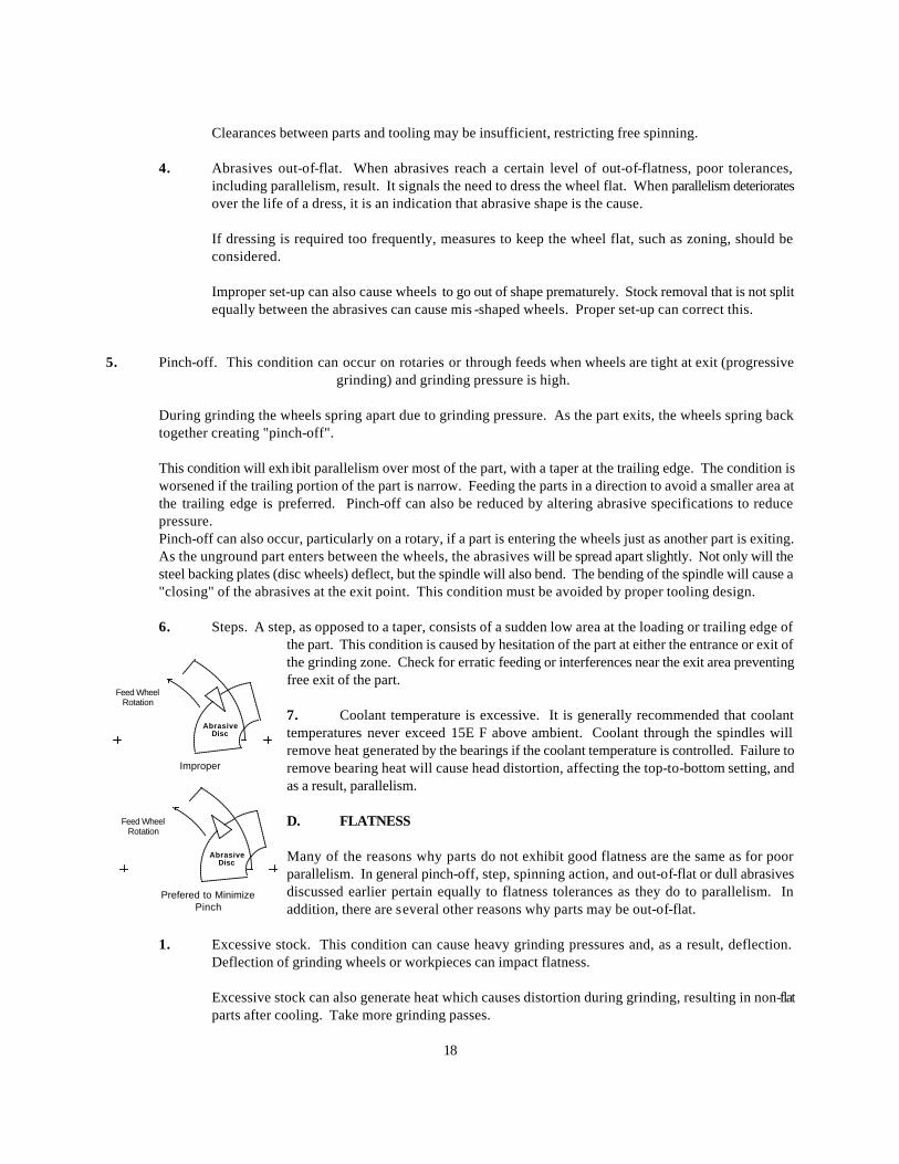
5. Pinch-off. This condition can occur on rotaries or through feeds when wheels are tight at exit (progressive
grinding) and grinding pressure is high.
During grinding the wheels spring apart due to grinding pressure. As the part exits, the wheels spring back together creating "pinch-off".
This condition will exh ibit parallelism over most of the part, with a taper at the trailing edge. The condition is worsened if the trailing portion of the part is narrow. Feeding the parts in a direction to avoid a smaller area at the trailing edge is preferred. Pinch-off can also be reduced by altering abrasive specifications to reduce pressure. Pinch-off can also occur, particularly on a rotary, if a part is entering the wheels just as another part is exiting. As the unground part enters between the wheels, the abrasives will be spread apart slightly. Not only will the steel backing plates (disc wheels) deflect, but the spindle will also bend. The bending of the spindle will cause a "closing" of the abrasives at the exit point. This condition must be avoided by proper tooling design.
6. Steps. A step, as opposed to a taper, consists of a sudden low area at the loading or trailing edge of
the part. This condition is caused by hesitation of the part at either the entrance or exit of the grinding zone. Check for erratic feeding or interferences near the exit area preventing free exit of the part. 7. Coolant temperature is excessive. It is generally recommended that coolant temperatures never exceed 15Ε F above ambient. Coolant through the spindles will remove heat generated by the bearings if the coolant temperature is controlled. Failure to remove bearing heat will cause head distortion, affecting the top-to-bottom setting, and as a result, parallelism. D. FLATNESS Many of the reasons why parts do not exhibit good flatness are the same as for poor parallelism. In general pinch-off, step, spinning action, and out-of-flat or dull abrasives discussed earlier pertain equally to flatness tolerances as they do to parallelism. In addition, there are several other reasons why parts may be out-of-flat.
1. Excessive stock. This condition can cause heavy grinding pressures and, as a result, deflection. Deflection of grinding wheels or workpieces can impact flatness.
Excessive stock can also generate heat which causes distortion during grinding, resulting in non-flat parts after cooling. Take more grinding passes.
AbrasiveDisc
Feed WheelRotation
Improper
AbrasiveDisc
Feed WheelRotation
Prefered to MinimizePinch
19
2. Incoming parts are out-of-flat. Parts that are distorted coming to the grinder will tend to distort to a
semi-flat shape during grinding. Even though the part may be ground to a good parallel condition, it will exhibit a curved shape after grinding. Even generate a flat ground part when incoming stock is excessively warped.
To correct this situation, the incoming part shape must be improved, or another grinding pass may be added to pre-condition the parts prior to a finish grind.
A slower feed rate may also improve the resulting flatness, because grinding pressure is reduced.
3. Excessive coolant temperature. If coolant temperature is more than 15Ε F above ambient, the effect on
part flatness can be damaging. Any workpiece at ambient temperature, when exposed to hot coolant, could have a tendency to "curl" during the grinding process. If a thermally distorted workpiece is ground flat, it will return to a non-flat condition after cooling.
4. Poor coolant delivery. Coolant must be presented to the workpiece/ wheel interface in order to
adequately remove the head generated during grinding. Inadequate coolant causes the workpiece to heat up. When a part heats up excessively, but perhaps not uniformly due to the quickness of grinding, may not be flat after it cools.
Parts that exit the grinder warm indicate improper or inadequate coolant delivery. Increase coolant flow and/or redirect coolant to more effectively cool the part/wheel interface.
5. Incorrect abrasive specification. The wrong abrasive can cause distortion of the part during grinding
due to excessive pressure. An abrasive that is dull or loaded will rub instead of cut and will generate heat, Heat, particularly if not generated uniformly on both sides, will cause the part to want to distort during the grind. After grinding, the part will not be flat.
Corrective action is an abrasive specification that remains consistently sharp.
6. Incorrect coolant type. For materials that are particularly heat sensitive it may be advisable to use a
soluble oil coolant that increases lubricity between the wheel and the part. Lubricity generally reduces power required to grind and also reduces the heat generated in grinding. Reduced heat generation will aid in obtaining flatness.
E. FINISH
Finish on a workpiece is a measure of the roughness of a machined or ground surface. Usually measured with a profilometer, at least two methods of calculating a finish "value" exist. One method is RMS (Root Mean Square) and the other is Ra (Arithmetic Average). Each method uses the distance between "peaks" and "valleys" as a basis for the calculation. If the finish is fairly uniform, the values calculated by each method will be approximately equal. However, if the distances between peaks and valleys vary considerably, the RMS value will be higher. Basically, the Ra value is more generally accepted today, as RMS lost popularity back in the 1950's.
Finish on a workpiece can either be too rough or too fine. In many cases, a finer than required finish is acceptable, but there are exceptions. A finish that is too good may not be advisable for the application, because this ability to hold good thickness tolerances and to remove heavy stock is compromised when abrasive specifications are primarily designed to achieve finish. The most accepted method of controlling finish on the workpiece is through the choice of grit size. With all other things equal, abrasives with a smaller grit size will act softer than those with large grains. However, depth of cut (stock) is limited by the length of abrasive grain
20
extending from the bond.
Finish Too Rough
Poor finish or finish that is too rough can have many causes/solutions.
1. Grit size may be too large. Try a smaller grit, but abrasives may need to be of a harder grade, and stock on the finishing pass may have to be reduced.
2. Coolant may be dirty. Clean the tank and check the filter.
3. Coolant may be too strong. Check the concentration and dilute if necessary. Maintain a pH of 7 - 9 to
prevent premature breakdown of the resinoid bond.
4. The abrasive may be overworked by excessive stock or a feed rate that is too high. Excessive "shelling" away of the grain will cause a rough finish.
5. Machine Vibration. Vibrations caused by sources such as bearing failure, improperly mounted
abrasives, out-of-balance abrasives, motors, nearby machinery, etc., can cause poor surface finis h. The source should be isolated and corrected. If environmental vibrations are the culprit, the machine should be isolated from its surroundings. (Consult machine manufacturer concerning recommended method of isolation). If coolant is permitted to flow on stationary abrasives, an out-of-balance condition is caused when the coolant is absorbed in one area. It is good practice to let the spindles run with the coolant flow shut off to permit the coolant to be thrown off, avoiding an out-of-balance condition. DO NOT EXCEED 5 MINUTES DRY RUNNING. ROTARY UNION SEAL DAMAGE MAY RESULT.
6. Time of contact between part and abrasives may be too short. Increased time on the abrasive through a
slower feed rate, a "tight at exit" head setting, or other means may help achieve a finer finish.
7. Abrasives may be too soft, resulting in an excessive breakdown rate. If this condition exists, it would also be evident when trying to maintain the thickness tolerance. Consider a new abrasive specification.
8. Dressing rate or depth of cut may be excessive. A slower dressing pass will achieve a smoother wheel
and finer finish. A lighter cut on the finishing dress pass will also result in a smoother abrasive face. The use of diamond clusters will allow faster will allow faster dressing cycle than single points and still maintain a smooth dress.
9. Insufficient coolant delivery to the grinding zone. If the grind zone is starved for coolant, an increased
abrasive breakdown rate may occur, resulting in a poor finish. Increase coolant to the grinding zone.
10. A hard abrasive can cause dresser vibration and a rough dress. To correct this condition, reduce depth of cut, speed of dress, and switch to diamond clusters.
11. Imbedded foreign matter in tooling or abrasive bond can cause scratching that will result in locally poor
finish.
12. For large solid areas of contact on piece parts, a considerable amount of loose abrasive can degrade the finish, particularly when shear grinding is involved. Getting the parts out from between the abrasives quickly after grinding is complete can reduce the exposure to loose grains and improve finish. Flushing away the loose grain with a high volume of coolant also will improve surface finish. For thin work having a solid face, manifolding the coolant through holes in the abrasive will aid in
21
flushing away loose grain.
13. An oil based coolant may be helpful if all other tolerances are being achieved. This type of coolant under light stock removal promotes a "rubbing" or "polishing" action, thereby improving finish.
Remember that after a fresh dress the finish will initially be rougher than after several parts have been ground. Let the abrasives "settle down" prior to evaluating the surface finish.
Finish Too Smooth
Finish that is too good or too smooth can be detrimental and may have a variety of causes.
1. The abrasive grain may be too small, if surface finish is consistent over time. Increase the grit size, but
consider going slightly softer with the grade if all other parameters are being satisfactorily met.
2. The wheels may be dull. Parts may be polished or burnished indicating that the abrasives are "rubbing" instead of cutting freely. A tell-tale size of this condition is a cycle of "rough-smooth-rough" parts, indicating that the wheels are not cutting consistently. Try working the abrasives harder by increasing the feed rate or the stock removal. This will induce faster wheel breakdown and may keep the abrasives cutting consistently at an acceptable surface finish.
Increasing the speed of dressing will open the wheel up more, causing it to cut more freely. Generally, wheels that are dressed open will tend to stay open.
Dressing with a single point diamond or cutters will also result in a sharper wheel. Dressing tools must be sharp to be effective. Replace dull dressing tools.
The grade of the wheel may be too hard. A softer grade or a more friable abrasive grain may achieve a more consistent cutting action.
3. The abrasive may be loaded. Dirty coolant can contaminate abrasives, plugging up spaces for chip
clearance and causing wheels to glaze.
Increase coolant flow to flush abrasives. Insure that coolant is being properly introduced to the grinding zone.
Again, the abrasive specifications could be changed to a softer grade. Increased breakdown can prevent wheel loading.
F. SCRATCHES
Scratches on a ground surface are undesirable marks superimposed on the underlying finish. They may be isolated to one local area on the part, or they may be so dense that the scratches change the appearance of finish altogether. Here are some potential causes of scratching.
1. The coolant may be dirty. Loose abrasive grit or other foreign particles may be contaminating the
coolant due to inadequate filtration. Trying to finish grind without a thorough cleaning following a roughing operation is just one example of such a condition. If this happens, clean the coolant tank and provide adequate filtration.
2. Perforations in the disc may be clogged with grit and grinding swarf. Switching to a plain faced
abrasive may be necessary.
22
3. The abrasive may have been contaminated with large grains or foreign material by the manufacturer.
4. Dislodged burrs, slag, etc., from the workpiece itself may come loose during the grind and be carried
across the face of the part. When such action is suspected, clean a few parts and check the results. Preconditioning of parts may be required in severe cases.
5. Voids in the workpieces being ground may contain contaminants. If this is suspected, again, clean
some parts and monitor results.
6. Abrasive grains that shell away during grinding and are rubbed or rolled across the face of the part can cause scratching. A large volume of coolant directed to the grinding zone will help flush these loose grains away from the wheel face before they can cause damage. Insufficient coolant flow can aggravate this condition, because excessive wheel breakdown is induced, creating even more loose grain. A rough dress can also create a condition of excessive wheel breakdown.
7. When grinding in a shear mode if is often beneficial to remove the parts quickly from between the
wheels after grinding is complete. This is particularly truce on large diameter full faced parts. An inclined feed system on a through feed machine may improve results. The use of air or coolant to create an exit force may work equally well.
8. Exit guides may contain embedded foreign material or protrusions. Exit guides should be reconditioned
if necessary.
9. A post process gauge may scratch a soft part if contact pressure is high. Pressure against the part by the gauge finder may need to be reduced. Changing the contact material of the probe may also eliminate scratching.
G. BURN
Burn results from temperatures generated in a workpiece of sufficient magnitude to cause metallurgical changes in the material. Burn is not necessarily visual, but severe burn can be easily detected. Non-visual burn can be detected by acid etch (Nitol) or by non-destructive checks for surface cracks, such as magnaflux or dye penetrant testing. In diagnosing the cause of burn, one must take note as to whether it is only periodic or is on every part.
Burns on every piece
When burn exists on every piece, the cause may be:
1. Coolant too hot. Increase cooling capacity by adding capacity (gallons and surface area) or a heat
exchanger of some type. Warm coolant will cause the parts to get warmer during the grind.
2. Coolant delivery to the grind zone may be insufficient. If the surface finish in the burned area looks normal (not polished or burnished), the problem may be lack of coolant to the grind zone. Check the pump lines and delivery of coolant.
3. Excessive feed rate or stock removal can cause power losses into the workpiece in the form of heat.
The rate at which heat energy is generated at the surface of the workpiece can be reduced by taking lighter stock or slowing down the feed rate. The surface temperature at the workpiece will be reduced, avoiding burn.
23
4. The abrasive may be dull or loaded, creating a rubbing action instead of efficient cutting. Rubbing generates heat. Analyze the burned area. If this area is polished or burnished, a dull abrasive is the cause. The solution is to try a softer wheel grade to achieve faster abrasive breakdown and a wheel that stay sharp. The wheel can be made to act softer by slowing it down if a softer grade is not readily available. Burn due to dull abrasives usually will coincide with inability to maintain thickness tolerances. Dull abrasives increase grinding pressures and create added machine deflection. Erratic abrasive usage will result. Check the diamonds for sharpness. A single point diamond or dresser cutter will produce a sharper wheel than cluster diamonds or rolls. A faster dressing pass will also improve wheel sharpness.
5. Head settings may be improper. If a progressive head setting is being used, a pure shear setting may
reduce burn, depending on the material. Reduced time that a part is in contact with the wheel, due to a shorter grind path, may prevent burns.
If a shear setting is used and burn is evident, changing to shear plus progression will reduce the "shock" of removing all stock at the entrance point. Burn may disappear or be removed during the progressive portion of the grind if not too deep.
On many applications, parts may burn following a fresh dress until a lead-in is developed on the abrasives. Once the lead-in is developed, the shock of heavy stock removal at the entrance is reduced. Leaving a lead-in after dressing or inducing a lead has been shown to eliminate burn on initial parts in many cases. A lead-in can be introduced either manually or automatically, depending upon machine features, in either a "taper" or "step" form.
Periodic burn
When burn is only periodic, check for the following causes:
1. Variation in stock removal. An occasional part with heavy stock can cause burn. More passes may be
required to reduce the maximum stock removal on any part.
2. Feed may be erratic. Occasional hesitation of parts in the grind zone may create enough additional heat to cause burn. Adjust the feed mechanism.
3. Coolant flow may fluctuate. Check the coolant system for restrictions and eliminate the cause
H. BLEMISHES AND MARKS
Objectionable marks on ground surfaces appear in several forms and may be measurable or just visual. Each form of blemish has distinct possible causes which are listed below. Most are a result of an improper set-up that must be corrected prior to continuing.
Discussion of blemishes is organized by general type and cause. Two terms are defined for purposes of discussion. These terms are "dubs" and "swipes".
1. A "dub" is an arbitrary choice of terms for a general type of blemish usually caused by a problem at the
ENTRANCE to the grind zone. Some chief causes are outlined below.
a. Entrance guides out of alignment with abrasives. These guide plates are designed to direct the work piece between the abrasives. If the guide presents the part at an angle, dubs will result.
24
b. Too much clearance between entrance guides and the part. Excessive clearance prevents the guides from adequately controlling direction of the part. Recommendations for clearances are .010" for rough operations and .004" for finishing.
c. Burrs or nicks on entrance guide. Any such protrusion will cause the part to enter the wheels misaligned.
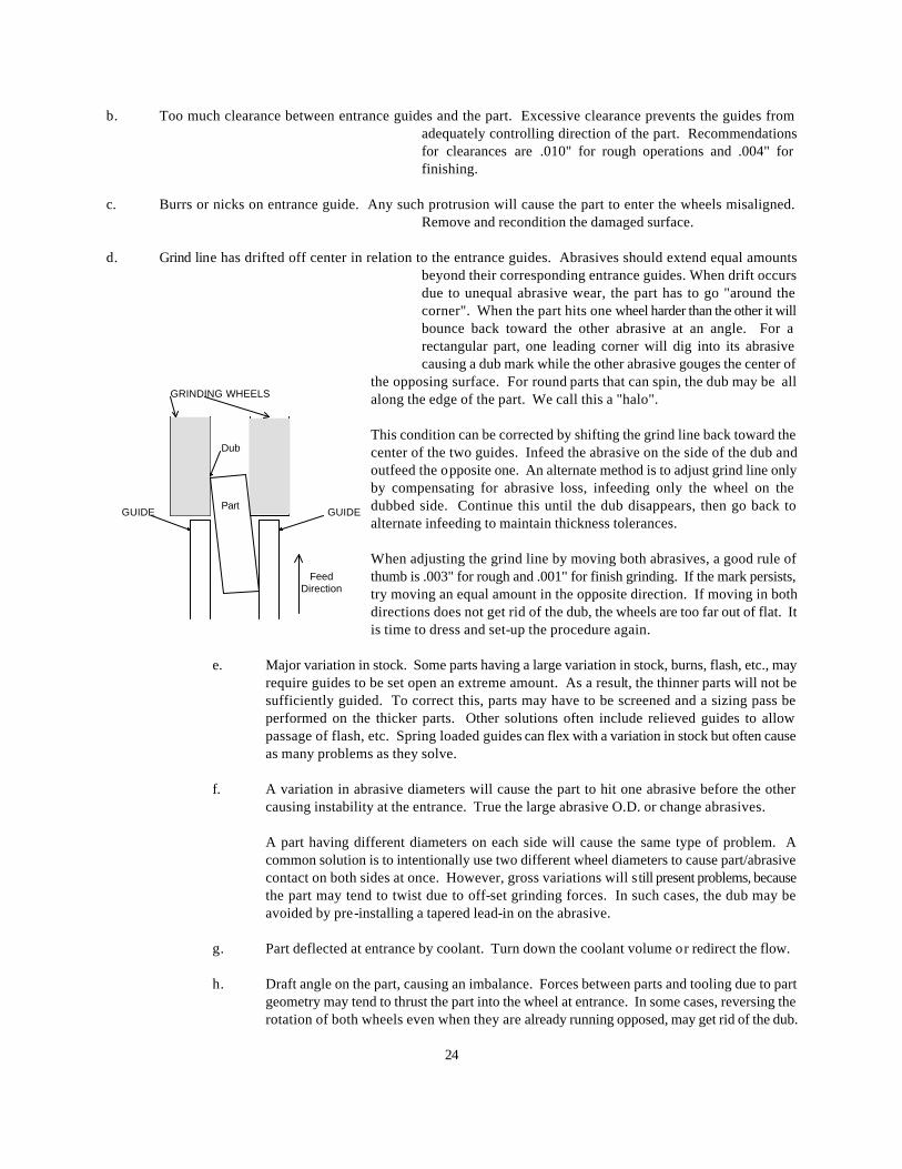
Remove and recondition the damaged surface. d. Grind line has drifted off center in relation to the entrance guides. Abrasives should extend equal amounts
beyond their corresponding entrance guides. When drift occurs due to unequal abrasive wear, the part has to go "around the corner". When the part hits one wheel harder than the other it will bounce back toward the other abrasive at an angle. For a rectangular part, one leading corner will dig into its abrasive causing a dub mark while the other abrasive gouges the center of
the opposing surface. For round parts that can spin, the dub may be all along the edge of the part. We call this a "halo". This condition can be corrected by shifting the grind line back toward the center of the two guides. Infeed the abrasive on the side of the dub and outfeed the opposite one. An alternate method is to adjust grind line only by compensating for abrasive loss, infeeding only the wheel on the dubbed side. Continue this until the dub disappears, then go back to alternate infeeding to maintain thickness tolerances. When adjusting the grind line by moving both abrasives, a good rule of thumb is .003" for rough and .001" for finish grinding. If the mark persists, try moving an equal amount in the opposite direction. If moving in both directions does not get rid of the dub, the wheels are too far out of flat. It is time to dress and set-up the procedure again.
e. Major variation in stock. Some parts having a large variation in stock, burns, flash, etc., may
require guides to be set open an extreme amount. As a result, the thinner parts will not be sufficiently guided. To correct this, parts may have to be screened and a sizing pass be performed on the thicker parts. Other solutions often include relieved guides to allow passage of flash, etc. Spring loaded guides can flex with a variation in stock but often cause as many problems as they solve.
f. A variation in abrasive diameters will cause the part to hit one abrasive before the other
causing instability at the entrance. True the large abrasive O.D. or change abrasives.
A part having different diameters on each side will cause the same type of problem. A common solution is to intentionally use two different wheel diameters to cause part/abrasive contact on both sides at once. However, gross variations will s till present problems, because the part may tend to twist due to off-set grinding forces. In such cases, the dub may be avoided by pre-installing a tapered lead-in on the abrasive.
g. Part deflected at entrance by coolant. Turn down the coolant volume or redirect the flow.
h. Draft angle on the part, causing an imbalance. Forces between parts and tooling due to part
geometry may tend to thrust the part into the wheel at entrance. In some cases, reversing the rotation of both wheels even when they are already running opposed, may get rid of the dub.
GRINDING WHEELS
GUIDEGUIDEPart
Dub
FeedDirection
25
I. A non-uniform feed rate can cause dubbing. Adjust the feed mechanism.
2. A Aswipe@ is a term used to describe a problem at the EXIT from the grind zone. Some primary causes
are mentioned.
a. Exit guides not adequately set behind the grind line. It is normally recommended that exit guides be set .010" behind entrance guides. Exit guides should not touch the part until it is entirely free from the abrasives.
b. Excess lead-in on the abrasives. When the lead-in at the entrance is large, more freedom is
also provided for the part as it exits. If it touches a guide, it could bounce back and hit an abrasive, causing a swipe. It is time to dress the abrasives.
c. Part imbalance. In shear grinding, all stock is removed between the entry point and the
centerhole. Once the centerhole is crossed, the part should not touch the abrasive. Imbalanced parts, such as bearing races, parts with draft angles, etc., should be removed as soon as possible to avoid swipes. An inclined part path, a coolant blast, etc., should be used to urge the part out quickly.
d. Part is restricted as it exits. Any restriction at the exit, such as gauge pack pressure will cause
swipes. Check for and remove the obstructions. Where back pressure cannot be avoided, a powered exit drive system should be employed that operates at a slightly faster rate than the feed system.
e. Part is deflected by coolant as it exits. In shear grinding the part should move freely from the
centerline to the exit point without touching the abrasives. Unequal or excessive coolant flow through the spindles can force parts into the grinding wheels, causing swipes.
I. THICKNESS
The challenge of maintaining desired thickness tolerances on a disc grinder varies dramatically between applications. As an example the following conditions would be ideal for holding size:
! Consistent stock on parts coming to grinder
! Small surface area on parts being ground
! A free cutting abrasive that stays sharp but does not wear to fast ! Surface finish not critical
! Only one part in the grind zone at a time
Although the set of conditions stated above is very rare in practice, the closer the application is to these, the tighter the resultant thickness tolerance can be.
The variation in thickness between parts in a production run can have six basic causes. Abrasive wear can be too high or erratic. Grinding pressure can be too high causing high or inconsistent deflection. Machine and human errors, as well as incoming part condition can cause fluctuations. The final problem in some types of grinders, particularly through feeds, is the delay between grinding and part measurement which creates an out of phase condition. Our discussion will revolve around these six basic causes, but remember that before thickness
26
can be held, parallelism must be under control. Also, remember that abrasives often need to "settle in" following a fresh dress. Therefore, do not make judgements based on running only a few parts. Finally, almost any change that we make regarding the abrasive specification to reduce the size variation will in all likelihood degrade the surface finish.
Abrasive Usage High or Erratic
Such a condition makes the ability to compensate for abrasive wear extremely difficult. Compensations must occur frequently and may not be controllable. Some causes of this condition are:
1. Abrasive grade too soft. Change abrasive specification, or increase spindle speed.
2. Coolant too hot. This can cause rapid abrasive wear. Add cooling capacity.
3. Excessive stock removal. Take more grinding passes.
4. Feed rate too fast. Adjust feed system.
High or Inconsistent Grinding Pressure
All mechanisms deflect under load. For holding precision thickness tolerances, the pressure must be minimized and machine stiffness maximized. Modern double disc grinders have dramatically improved stiffness compared to their predecessors, but control of grinding pressure is still necessary. Some of the causes of excessive pressure are discussed below:
1. Abrasives may be dull. This is caused by insufficient breakdown preventing the exposure of new
sharp cutting points. When size varies considerably and the finish goes through cycles of high to low, it is a sign that abrasives are not consistently cutting (dull). When grinding pressure builds up on a dulled wheel, it will eventually "shell" away, suddenly becoming sharp. This inconsistency creates havoc when trying to maintain size. An obvious cause might be that the wheel grade is too hard. Switch to a softer wheel grade or try slowing down the spindle speed.1 A more friable grain may also help since it fractures easily exposing new sharp cutting points.
A faster feed rate will work the abrasive harder, inducing breakdown. Try speeding up the parts feeding fixture.
1 When slowing the spindle speed to cause the abrasive to act softer, remember that inner zones will not
experience as much change in behavior as the outer periphery. If the wheel were zoned based upon the faster speed, the zoning may not be effective at slower speeds.
Dressing tools may be dull or incorrect for the application. Diamonds must be sharp to be effective. A dull diamond will dress a dull wheel. Single point diamonds will generate sharper wheels than clusters or rolls. Dresser cutters are even better. An abrasive disc will tend to remain in its dressed condition, so dressing is very important.
A faster dressing cycle or a heavier dressing cut may help sharpen the wheel. When considering this, note that finish may get worse.
27
2. Head settings may be improper. If progressive settings are in use, heavy grinding and feeding
pressure may result. If so, try a little less progression and more shear grinding. This should reduce pressure.
3. Abrasives may be loaded. Contaminated coolant or heavy oil based coolants can cause abrasives to
load up. When this occurs, abrasives will appear dirty and pores will be clogged. Clean the coolant tank and change coolant type if necessary.
The coolant mixture may be too strong, causing loading. Dilute coolant strength and maintain a pH of 7 - 9.
Wheels may be loaded with material from work pieces. If this is evident, review the abrasive specification and consider changing abrasive grain types or switch to a softer grade.
In each case, dress the abrasives after taking corrective action.
4. Stock removal may be too high. Watch dial indicators in the grinding heads. If they move when filling
or clearing the grind zone, try reducing stock remo val and take more grinding passes.
Machine Errors
Feed rates may be erratic or the compensating infeed mechanisms may not be working properly. When this is suspected check the feeder mechanism and correct as necessary. Use dial indicators mounted in the grinding heads to check accuracy and consistency of infeeds.
Worn or bad spindle bearings, inoperable anti-backlash systems, or insufficient anti-backlash cylinder air pressure are other potential causes that must be considered
Human Error
Regardless of the potential of a process, no end result will be better than the operator. Lack of attention to details such as infeed increment setting, etc., will have a detrimental impact on the resulting size band. An operator must develop a "feel" for his machine and the process. Once this is accomplished, thickness tolerances will improve.
Even for a reasonably correct abrasive for the job, a degree of skill may be required to start up and successfully continue to process. After a fresh dress, the abrasive will wear away quickly until it stabilizes. Initially, the infeed increment may need to be set high to help keep up with abrasive loss. After the discs "settle", a smaller infeed increment would be better. However, sometimes the shock of compensating (sudden feed of abrasive into the work piece) will break the wheel down causing it to stay sharp. Smaller, more frequent compensations may not keep the discs sharp.
Incoming Part Condition
Machine deflection is directly related to the amount of stock remo ved from work pieces. Good thickness control depends upon keeping the deflections small, but also consistent. Therefore, to expect consistent part thickness from the process, the incoming parts must not vary too much. This is one reason many precision parts need several passes. Thickness tolerances will be improved on each pass if the process is under control. Generally speaking, if the variation of incoming parts is more than 2-4 times the finished tolerance range, a pre-conditioning pass will be necessary.
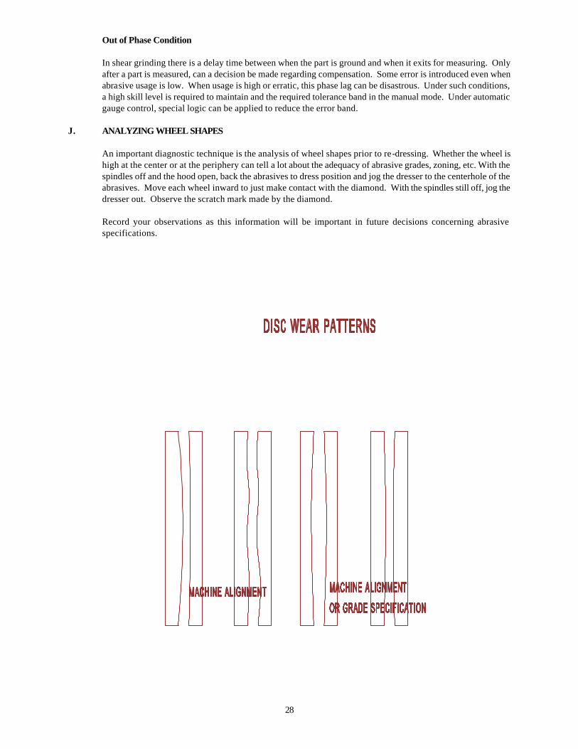
28
Out of Phase Condition
In shear grinding there is a delay time between when the part is ground and when it exits for measuring. Only after a part is measured, can a decision be made regarding compensation. Some error is introduced even when abrasive usage is low. When usage is high or erratic, this phase lag can be disastrous. Under such conditions, a high skill level is required to maintain and the required tolerance band in the manual mode. Under automatic gauge control, special logic can be applied to reduce the error band.
J. ANALYZING WHEEL SHAPES
An important diagnostic technique is the analysis of wheel shapes prior to re-dressing. Whether the wheel is high at the center or at the periphery can tell a lot about the adequacy of abrasive grades, zoning, etc. With the spindles off and the hood open, back the abrasives to dress position and jog the dresser to the centerhole of the abrasives. Move each wheel inward to just make contact with the diamond. With the spindles still off, jog the dresser out. Observe the scratch mark made by the diamond.
Record your observations as this information will be important in future decisions concerning abrasive specifications.
29
IV. GLOSSARY OF TERMS
TERM DEFINITION
Abrasive Also called ABRASIVE DISC, NUT INSERTED DISC, WHEEL, OR GRINDING WHEEL. The "cutting tool" used to remove stock from workpieces in double disc grinding. It is cylindrically shaped, having an I.D. and O.D. It is supported from the back face and removes stock using the front face.
Adjusting Slide Previously referred to as a CHUCKING CYLINDER or
CHUCKING PLATE. This device is the adjusting and slide mechanism for an adjustable entrance or exit guide.
Alignment The geometry relationships between the two grinding wheels,
parts feeding fixture and the entrance and exit guides.
Anti-Backlash System An actuator that pulls rearward on the quill, eliminating backlash in the infeed system and preloads the quill in its housing. Typically includes an air cylinder on horizontal grinders and a hydraulic cylinder on a vertical grinder.
Back Pressure Compression forces on the exiting stream of workpieces from a
throughfeed grinder. Such forces can be caused by post-process gauges or other downstream mechanisms. An exit drive roll or an inclined part path is often used to alleviate back pressure.
Bushing A round work holder in a rotary feedwheel or oscillator paddle
used to hold the workpiece.
Centerhole The void region inside the I.D. of an abrasive disc. The diameter of the centerhole varies between applications and is very small on throughfeed machines, only large enough to permit the passage of coolant through the spindle.
Cycle Time (Machine) Time required for the machine to grind one workpiece.
Cycle Time (Floor-to-Floor) Average time that a grinding machine must be available to
process (grind/load/unload/ gauge/etc.) one workpiece.
Disc Wheel Also called a STEEL BACK or a BACKING PLATE. It provides the mounting surface for the abrasive disc and supports it structurally. The disc wheel is usually made of steel and bolts directly onto the spindle flange.
Entrance Guides Also called GUIDE PLATES. Wear resistant metallic plates used
to accurately guide the unground workpiece as it enters between the abrasives. usually consists of one left hand and one right hand guide.
Exit Drive Also called EXIT ROLL. A powered device to assist workpieces
along a desired path (on a through feed machine) after exiting from between the grinding wheels. Usually is adjusted to drive workpieces slightly faster than the feeding mechanism, thus avoiding unnecessary compression of the stream of workpieces between the abrasives.
Exit Guides Also called GUIDE PLATES. Wear resistant metallic plates used
30
to guide the workpieces, after they exit from between the abrasives, along any desired post-grind path. Usually consists of one left hand and one right hand guide. They do not touch the workpiece until it is completely free from the abrasives.
Feed Rate The rate of travel, usually in inches per minute, of an abrasive
when plunge grinding a workpiece.
Feed Wheel Also called a ROTARY CARRIER, CARROUSEL, OR FERRIS WHEEL. A round plate with multiple openings to accept workpieces. It is used to drive workpieces along a circular path between the opposed abrasives.
Floating Also called NESTING. Refers to a method of holding a workpiece
in its workholder while grinding. This method allows the workpiece to self center while grinding as opposed to "clamping" the part.
Gauge Also called a SIZER. On a double disc grinder this device
typically is used to measure the thickness of ground workpieces. The device may be "in-process" (oscillator) or "post process" (all others) and may be manual or automatic. Gauge signals may be used to automatically compensate the grinding machine for thickness changes or the read-out may provide a "visual only" output.
Gauge Finger Also called PROBE. A wear resistant device used to contact the
ground surface of the workpiece for the purpose of measuring part size (thickness). A gauge finger can be used to measure a workpiece either during the grind (oscillator machine/in-process gauging) or after the grind (Post process).
Grind Line A double disc grinder would have two grind lines, right and left.
It is the intersection of the workpiece surface with the abrasive during grinding. It is not a true line, but would be plane on a freshly trued set of abrasives.
Grind Path Also called PART PATH. The path travelled by a workpiece
while it makes contact with the abrasive face.
Grind Zone The path of the workpiece as it passes between the opposed abrasives.
Guide Bars Also called RAILS OR GUIDE RAILS. Wear resistant steel bars
used on a through feed type double disc grinder. Upper and lower guidebars contain the workpieces in the vertical direction as they pass through the feeding mechanism, the grinding wheels, and any machine mounted thickness gauge.
Guide Bar Spacer A precision spacer placed between the guide bars and the left
hand entrance/exit guides. These spacers are configured to center the guide bars to the workpiece on the throughfeed grinder.
Guide Bracket A structure to which a "fixed" entrance or exit guide is attached.
Head An assembly containing the main grinding wheel spindle, the
abrasive feeding mechanism, and the slide.
31
Head Setting The geometric relationship of the two opposed grinding wheels
to each other when trued to a flat condition. A measure of the change in gap between the abrasives, usually stated in terms of "front-to-back" and "top-to-bottom".
Hood A structural part of a double disc grinder used to act as a
wheelguard, contain coolant, and support the truing device as well as some less critical tooling. On some older machines, the hood also supports parts feeding fixtures.
In-feed Also called "PICK" FEED, COMPENSATION, INCREMENTAL
FEED. The motion of an abrasive to make up for the fact that the face wears away during the grinding process. The amount of movement is a pre-selected amount occurring at a frequency required to maintain the proper grind line.
Left Hand The end of a double disc grinder as observed from the
workpieces entry side.
Oscillation Also called a STROKE. This is one inward and outward cycle of a workpiece between the abrasives on an oscillating type double disc grinder.
Oscillator A double disc grinder with a pivoting style workpiece feeding
mechanis m that oscillates the workpieces between the abrasives, from O.D. to I.D., a pre-set number of cycles. The abrasives simultaneously plunge inward at a programmed cycle to remove stock.
pH The degree of acidity of alkalinity of a solution. pH7 is regarded s
neutral (pure distilled water). pH values from 0 to 7 indicate acidity and from 7 to 14 indicate alkalinity.
Plunge Grind Also called FACE GRIND. A grinding cycle where the abrasives
feed into the workpiece at programmed rates to remove stock. Used on oscillating type double disc grinders and some other miscellaneous types.
Pusher Bar A straight bar of rectangular cross-section used to push
workpieces (one at a time) through the grind zone on a long stroke pusher feeder type double disc grinder.
Quill Also called a SLEEVE or WHEEL SLEEVE. A cylindrically
shaped precision slide used for moving the abrasive along the spindle axis. Houses the grinding wheel spindle and its bearings.
Right Hand The end of a double disc grinder as observed from the workpiece
entry side.
Rotary Fixture A transmission used to support and transmit torque to the feedwheel. Usually includes variable speed adjustments. The feedwheel is mounted by bolting to an integral flange (rotary hub) on one end of the rotary fixture spindle.
Rotary Hub The flange integral to the rotary fixture spindle. Used for
mounting the feedwheel.
32
Shelling Refers to the action of an abrasive whereby the usage or breakdown is excessive. Shelling is not desirable, because thickness and finish tolerances are difficult to achieve under this condition.
Size Refers to the thickness of a finish ground workpiece.
Spindle A rotating shaft, supported by bearings, bushings, etc. Often referring to the shaft that supports the grinding wheel.
Spindle Flange Also called WHEEL COLLAR. The flange at the end of the
spindle (usually integral to the spindle) used for mounting the grinding wheel and its' steel backing plate.
Spindle Speed The rate of rotation of the main grinding spindle, usually
measured in revolutions per minute.
Spin Grinding When the workpiece is allowed or forced to spin while being ground, tolerances can often by improved. Spin grinding generally results in a cross-hatched surface finish on the workpiece.
Stock The amount to be ground off a workpiece, either in total or per
"pass". Usually is measured in inches (or millimeters), or could be stated in cubic inches per workpiece. In double disc grinding, it represents the amount in total to be ground off both sides. For example, if each side had .005" to be removed, the workpiece would contain .010" stock.
Surface Area Usually referring to the surface area of the grinding stock on a
workpiece.
Tooling A general term relating to parts of the grinder that make contact with the workpieces. Tooling is typically made from wear resistant material but is generally considered replaceable.
Wheel Positioner A device that detects the location of an abrasive face. Wheel
positioners can be either contact or non-contact type and are usually used to monitor the location of only one abrasive disc.
Wheel Shapes The deviation in the shape of an abrasive face from a flat surface.
Workholder Also called a POCKET or a RETAINER. This is an item of tooling
which restrains the workpiece during grinding. The workholder can either "clamp" or simply "nest" the part.
Workholding Paddle Also referred to as simply the PADDLE, WORKHOLDER,
BLADE, etc. A device used on an oscillating type double disc grinder to contain and drive the workpiece while grinding.
Workpiece Also called the PART or PART PIECE. This is the item being
ground by the grinding machine.
Zip-Zip Also called SHUTTLE grinding. This refers to a style of grinding using an oscillating type parts feeder. In this case the abrasives are fixed during a grind cycle and move inward between cycles only to compensate for abrasive wear. Each workpiece enters the abrasives, goes to the I.D. and then back out again to be unloaded. This single stroke is referred to as "zip-zip" style.
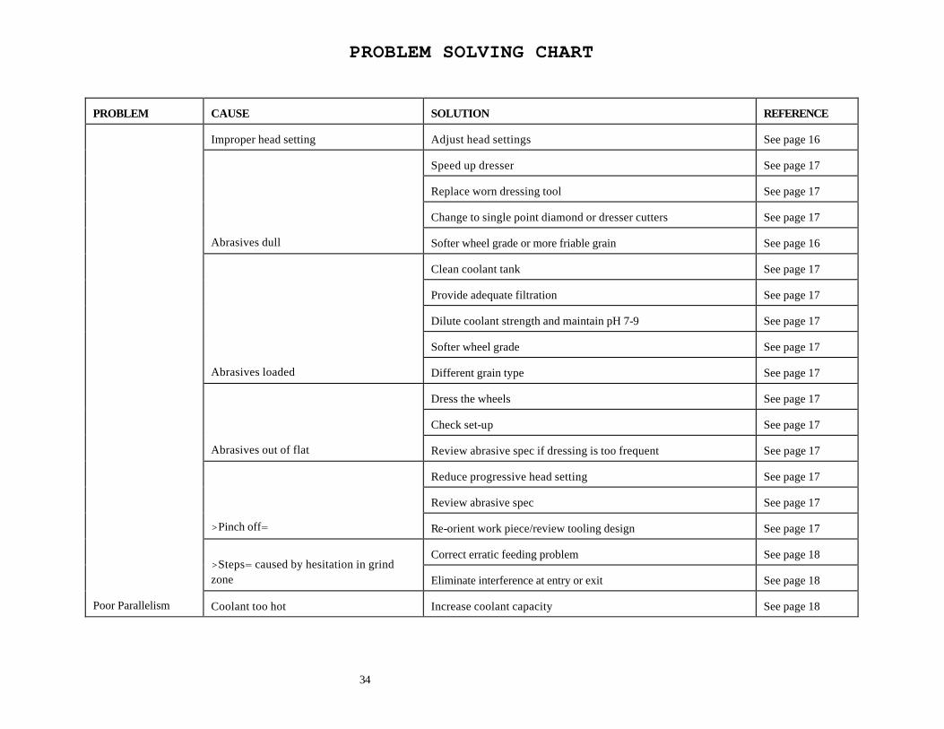
PROBLEM SOLVING CHART
34
PROBLEM
CAUSE
SOLUTION
REFERENCE
Improper head setting
Adjust head settings
See page 16
Speed up dresser
See page 17
Replace worn dressing tool
See page 17
Change to single point diamond or dresser cutters
See page 17
Abrasives dull
Softer wheel grade or more friable grain
See page 16
Clean coolant tank
See page 17
Provide adequate filtration
See page 17
Dilute coolant strength and maintain pH 7-9
See page 17
Softer wheel grade
See page 17
Abrasives loaded
Different grain type
See page 17
Dress the wheels
See page 17
Check set-up
See page 17
Abrasives out of flat
Review abrasive spec if dressing is too frequent
See page 17
Reduce progressive head setting
See page 17
Review abrasive spec
See page 17
>Pinch off=
Re-orient work piece/review tooling design
See page 17
Correct erratic feeding problem
See page 18
>Steps= caused by hesitation in grind zone
Eliminate interference at entry or exit
See page 18
Poor Parallelism
Coolant too hot
Increase coolant capacity
See page 18
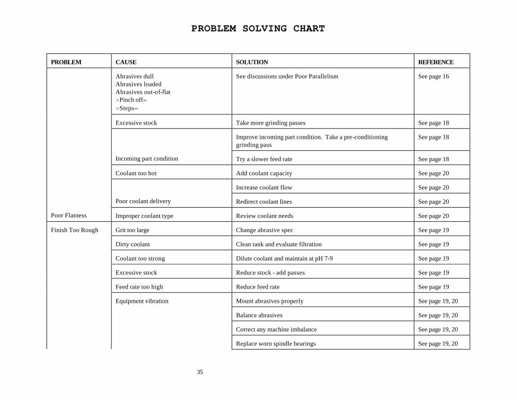
PROBLEM SOLVING CHART
35
PROBLEM
CAUSE
SOLUTION
REFERENCE
Abrasives dull Abrasives loaded Abrasives out-of-flat >Pinch off= >Steps=
See discussions under Poor Parallelism
See page 16
Excessive stock
Take more grinding passes
See page 18
Improve incoming part condition. Take a pre-conditioning grinding pass
See page 18
Incoming part condition
Try a slower feed rate
See page 18
Coolant too hot
Add coolant capacity
See page 20
Increase coolant flow
See page 20
Poor coolant delivery
Redirect coolant lines
See page 20
Poor Flatness
Improper coolant type
Review coolant needs
See page 20
Grit too large
Change abrasive spec
See page 19
Dirty coolant
Clean tank and evaluate filtration
See page 19
Coolant too strong
Dilute coolant and maintain at pH 7-9
See page 19
Excessive stock
Reduce stock - add passes
See page 19
Feed rate too high
Reduce feed rate
See page 19
Mount abrasives properly
See page 19, 20
Balance abrasives
See page 19, 20
Correct any machine imbalance
See page 19, 20
Finish Too Rough
Equipment vibration
Replace worn spindle bearings
See page 19, 20
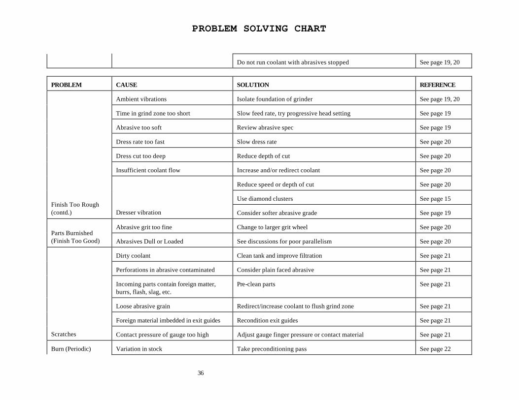
PROBLEM SOLVING CHART
36
Do not run coolant with abrasives stopped
See page 19, 20
PROBLEM
CAUSE
SOLUTION
REFERENCE
Ambient vibrations
Isolate foundation of grinder
See page 19, 20
Time in grind zone too short
Slow feed rate, try progressive head setting
See page 19
Abrasive too soft
Review abrasive spec
See page 19
Dress rate too fast
Slow dress rate
See page 20
Dress cut too deep
Reduce depth of cut
See page 20
Insufficient coolant flow
Increase and/or redirect coolant
See page 20
Reduce speed or depth of cut
See page 20
Use diamond clusters
See page 15
Finish Too Rough (contd.)
Dresser vibration
Consider softer abrasive grade
See page 19
Abrasive grit too fine
Change to larger grit wheel
See page 20
Parts Burnished (Finish Too Good)
Abrasives Dull or Loaded
See discussions for poor parallelism
See page 20
Dirty coolant
Clean tank and improve filtration
See page 21
Perforations in abrasive contaminated
Consider plain faced abrasive
See page 21
Incoming parts contain foreign matter, burrs, flash, slag, etc.
Pre-clean parts
See page 21
Loose abrasive grain
Redirect/increase coolant to flush grind zone
See page 21
Foreign material imbedded in exit guides
Recondition exit guides
See page 21
Scratches
Contact pressure of gauge too high
Adjust gauge finger pressure or contact material
See page 21
Burn (Periodic)
Variation in stock
Take preconditioning pass
See page 22
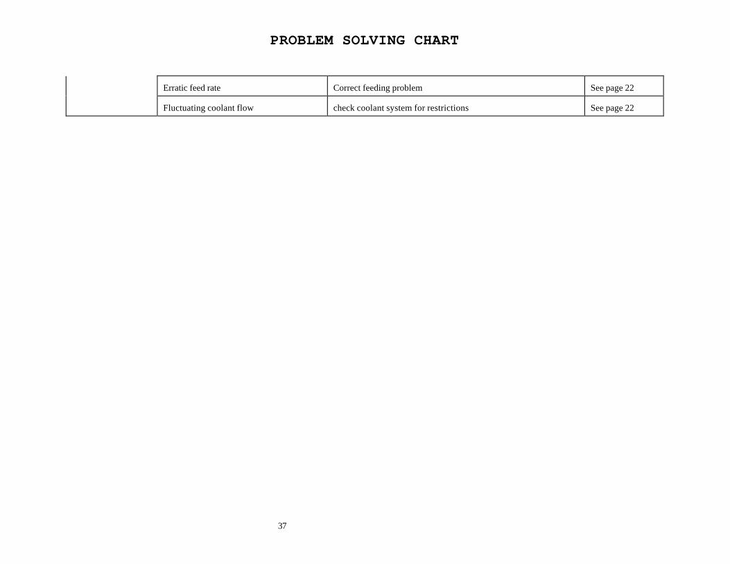
PROBLEM SOLVING CHART
37
Erratic feed rate
Correct feeding problem
See page 22
Fluctuating coolant flow
check coolant system for restrictions
See page 22
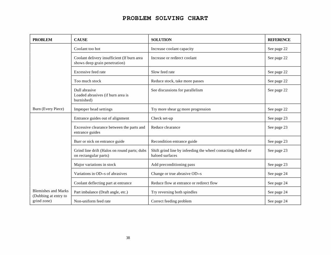
PROBLEM SOLVING CHART
38
PROBLEM
CAUSE
SOLUTION
REFERENCE
Coolant too hot
Increase coolant capacity
See page 22
Coolant delivery insufficient (If burn area shows deep grain penetration)
Increase or redirect coolant
See page 22
Excessive feed rate
Slow feed rate
See page 22
Too much stock
Reduce stock, take more passes
See page 22
Dull abrasive Loaded abrasives (if burn area is burnished)
See discussions for parallelism
See page 22
Burn (Every Piece)
Improper head settings
Try more shear or more progression
See page 22
Entrance guides out of alignment
Check set-up
See page 23
Excessive clearance between the parts and entrance guides
Reduce clearance
See page 23
Burr or nick on entrance guide
Recondition entrance guide
See page 23
Grind line drift (Halos on round parts; dubs on rectangular parts)
Shift grind line by infeeding the wheel contacting dubbed or haloed surfaces
See page 23
Major variations in stock
Add preconditioning pass
See page 23
Variations in OD=s of abrasives
Change or true abrasive OD=s
See page 24
Coolant deflecting part at entrance
Reduce flow at entrance or redirect flow
See page 24
Part imbalance (Draft angle, etc.)
Try reversing both spindles
See page 24
Blemishes and Marks (Dubbing at entry to grind zone)
Non-uniform feed rate
Correct feeding problem
See page 24
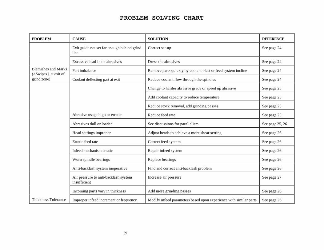
PROBLEM SOLVING CHART
39
PROBLEM
CAUSE
SOLUTION
REFERENCE
Exit guide not set far enough behind grind line
Correct set-up
See page 24
Excessive lead-in on abrasives
Dress the abrasives
See page 24
Part imbalance
Remove parts quickly by coolant blast or feed system incline
See page 24
Blemishes and Marks (ASwipes@ at exit of grind zone)
Coolant deflecting part at exit
Reduce coolant flow through the spindles
See page 24
Change to harder abrasive grade or speed up abrasive
See page 25
Add coolant capacity to reduce temperature
See page 25
Reduce stock removal, add grinding passes
See page 25
Abrasive usage high or erratic
Reduce feed rate
See page 25
Abrasives dull or loaded
See discussions for parallelism
See page 25, 26
Head settings improper
Adjust heads to achieve a more shear setting
See page 26
Erratic feed rate
Correct feed system
See page 26
Infeed mechanism erratic
Repair infeed system
See page 26
Worn spindle bearings
Replace bearings
See page 26
Anti-backlash system inoperative
Find and correct anti-backlash problem
See page 26
Air pressure to anti-backlash system insufficient
Increase air pressure
See page 27
Incoming parts vary in thickness
Add more grinding passes
See page 26
Thickness Tolerance
Improper infeed increment or frequency
Modify infeed parameters based upon experience with similar parts
See page 26