Embed Size (px)
Citation preview
Distributorless Ignition System AdapterUser Manual
©2009 Snap-on Incorporated. All rights reserved. ZEETA309A15 Rev. D
Distributorless IgnitionSystem Adapter
User Manual
November 2009
ZEETA309A15 Rev. D
TrademarksMODIS and Snap-on are trademarks of Snap-on Incorporated, registered in the United States and other countries.
All other marks are trademarks or registered trademarks of their respective holders.
Copyright Information©2009 Snap-on Incorporated. All rights reserved.
Disclaimer of Warranties and Limitation of LiabilitiesThe information, specifications and illustrations in this manual are based on the latest information available at the time of printing. While the authors have taken due care in the preparation of this manual, nothing contained herein:
• Modifies or alters in any way the standard terms and conditions of the purchase, lease, or rental agreement under the terms of which the equipment to which this manual relates was acquired.
• Increases in any way the liability to the customer or to third parties.
Snap-on reserves the right to make changes at any time without notice.
IMPORTANT:Before operating or maintaining this unit, please read this manual carefully paying extra attention to the safety warnings and precautions.
Visit our websites at:snapon.com (North America)
snapondiag.com (United Kingdom)
sun-diagnostics.com (United Kingdom)
For Technical Assistance Call1-800-424-7226 (North America)
CALL +44 (0) 845 601 4736 (United Kingdom)
E-mail [email protected] (United Kingdom)
For technical assistance in all other markets, contact your selling agent.
ii
Safety Information
For your own safety and the safety of others, and to prevent damage to the equipment and vehicles upon which it is used, it is important that these Safety Messages be read and understood by all persons operating, or coming into contact with, the equipment.
This product is intended for use by properly trained and skilled professional automotive technicians. The safety messages presented throughout this manual are reminders to the operator to exercise extreme care when using this test instrument.
There are many variations in procedures, techniques, tools, and parts for servicing vehicles, as well as in the skill of the individual doing the work. Because of the vast number of test applications and variations in the products that can be tested with this instrument, we cannot possibly anticipate or provide advice or safety messages to cover every situation. It is the automotive technician’s responsibility to be knowledgeable of the system being tested. It is essential to use proper service methods and test procedures. It is important to perform tests in an appropriate and acceptable manner that does not endanger your safety, the safety of others in the work area, the equipment being used, or the vehicle being tested.
It is assumed that the operator has a thorough understanding of vehicle systems before using this product. Understanding of these system principles and operating theories is necessary for competent, safe and accurate use of this instrument.
Before using the equipment, always refer to and follow the safety messages and applicable test procedures provided by the manufacturer of the vehicle or equipment being tested. Use the equipment only as described in this manual.
Read, understand and follow all safety messages and instructions in this manual, the accompanying safety manual, and on the test equipment.
Safety Message ConventionsSafety messages are provided to help prevent personal injury and equipment damage. All safety messages are introduced by a signal word indicating the hazard level.
! DANGERIndicates an imminently hazardous situation which, if not avoided, will result in death or serious injury to the operator or to bystanders.
! WARNINGIndicates a potentially hazardous situation which, if not avoided, could result in death or serious injury to the operator or to bystanders.
! CAUTIONIndicates a potentially hazardous situation which, if not avoided, may result in moderate or minor injury to the operator or to bystanders.
iii

Safety Information Important Safety Instructions
Safety messages contain three different type styles.
• Normal type states the hazard.• Bold type states how to avoid the hazard.• Italic type states the possible consequences of not avoiding the hazard.
An icon, when present, gives a graphical description of the potential hazard.
Example:
! WARNINGRisk of unexpected vehicle movement.• Block drive wheels before performing a test with engine running.
A moving vehicle can cause injury.
Important Safety InstructionsFor a complete list of safety messages, refer to the accompanying safety manual.
SAVE THESE INSTRUCTIONS
iv
Contents
Safety Information ..................................................................................................................... iii
Contents ...................................................................................................................................... v
Chapter 1: Using This Manual ................................................................................................... 1Conventions.................................................................................................................................. 1
Bold Text ................................................................................................................................ 1Symbols ................................................................................................................................. 1Terminology ........................................................................................................................... 2Notes and Important Messages ............................................................................................. 2Procedures............................................................................................................................. 2
Chapter 2: Introduction.............................................................................................................. 3Functional Description .................................................................................................................. 3Kit Contents .................................................................................................................................. 3Layout........................................................................................................................................... 5
Chapter 3: Getting Started......................................................................................................... 7Connecting to the Diagnostic Tool................................................................................................ 7DIS Adapter Operation ................................................................................................................. 7Preparing the Vehicle ................................................................................................................... 8Connecting to Coil and Plug Wires............................................................................................... 8
Connecting to Coils or Caps .................................................................................................. 9Coil Pickups ........................................................................................................................... 9Connecting to Ignition Systems ........................................................................................... 12
Chapter 4: Operation................................................................................................................ 17Interpreting test results ............................................................................................................... 17Troubleshooting.......................................................................................................................... 17
Polarity Issues...................................................................................................................... 18Wasted Spark Systems........................................................................................................ 19Synchronization ................................................................................................................... 19Inverted Signal ..................................................................................................................... 20Pickup Not Connected to a Cylinder .................................................................................... 21Incorrect polarity setup......................................................................................................... 21Reversed Measuring Leads ................................................................................................. 22
Chapter 5: Maintenance ........................................................................................................... 23Disposal of the DIS Adapter ....................................................................................................... 23
Appendix A: Ignition Waveforms ............................................................................................ 25The Ignition Cycle....................................................................................................................... 26
Appendix B: Coil Adapters ...................................................................................................... 29Coil-in-cap Adapters ................................................................................................................... 29Coil-on-plug Adapters................................................................................................................. 30
Appendix C: Coil Information.................................................................................................. 37
v

Contents
vi
Chapter 1 Using This Manual
This manual contains instructions for using the DIS Adapter.
Some of the illustrations shown in this manual may contain modules and optional equipment that are not included on your system. Contact your sales representative for availability of other modules and optional equipment.
1.1 ConventionsThe following conventions are used.
1.1.1 Bold TextBold emphasis is used in procedures to highlight selectable items such as buttons and menu options.
Example:
• Press the Y/a button.
1.1.2 SymbolsDifferent types of arrows are used.
The “greater than” arrow (>) indicates an abbreviated set of selection instructions.
Example:
• Select Utilities > Tool Setup > Date.
The example statement abbreviates the following procedure:
1. Navigate to the Utilities button.2. Use the Thumb Pad to navigate to and highlight the Tool Setup submenu.3. Use the Thumb Pad to navigate to and highlight the Date option from the submenu.4. Press Y/a to confirm the selection.
The solid arrows (e, c, d, b) are navigational instructions referring to the four directions of the Thumb Pad.
Example:
• Press the down d arrow.
1
Using This Manual Conventions
1.1.3 TerminologyThe term “select” means highlighting a button or menu item using the Thumb Pad and pressing the Y/a button to confirm the selection.
Example:
• Select Reset.
The above statement abbreviates the following procedure:
1. Navigate to and highlight the Reset button.2. Press the Y/a button.
1.1.4 Notes and Important MessagesThe following messages are used.
NotesA NOTE provides helpful information such as additional explanations, tips, and comments.
Example:
NOTE:i For additional information refer to...
ImportantIMPORTANT indicates a situation which, if not avoided, may result in damage to the test equipment or vehicle.
Example:
IMPORTANT:Do not force the CompactFlash® card into the slot.
1.1.5 ProceduresAn arrow icon indicates a procedure.
Example:
z To change screen views:1. Select the View button.
The drop-down menu displays.2. Select an option from the menu.
The screen layout changes to the format you selected.
2
Chapter 2 Introduction
The DIS Adapter is designed to be used with the MODIS™ Lab Scope Plug-in. Refer to the appropriate tool manual for operational information.
2.1 Functional DescriptionThe DIS Adapter relays the signals from pickups as input to the MODIS Lab Scope Plug-in. The scope processes the signals and displays them on the screen. The DIS Adapter can be used to sample and display the following ignition types secondary ignition signals:
• Distributor—with one or more coils and distributors or the coil fitted in the distributor cap.• Wasted Spark— with one coil for every 2 spark plugs.• Direct—with one coil per spark plug.
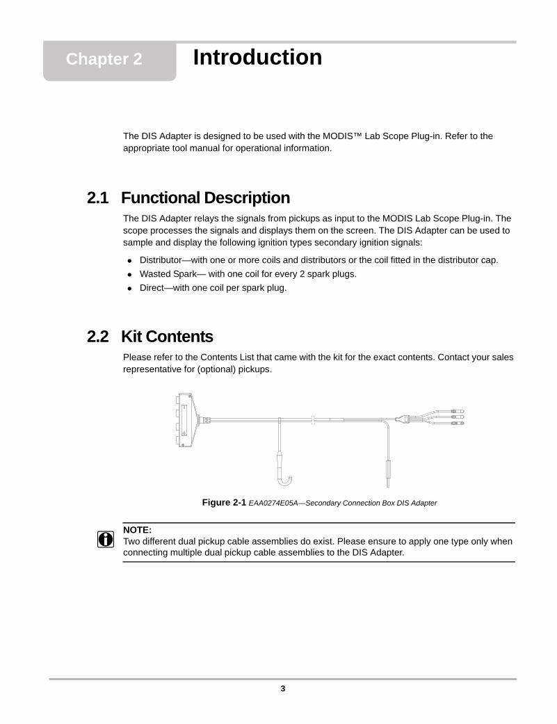
2.2 Kit ContentsPlease refer to the Contents List that came with the kit for the exact contents. Contact your sales representative for (optional) pickups.
Figure 2-1 EAA0274E05A—Secondary Connection Box DIS Adapter
NOTE:i Two different dual pickup cable assemblies do exist. Please ensure to apply one type only when
connecting multiple dual pickup cable assemblies to the DIS Adapter.
3
Introduction Kit Contents
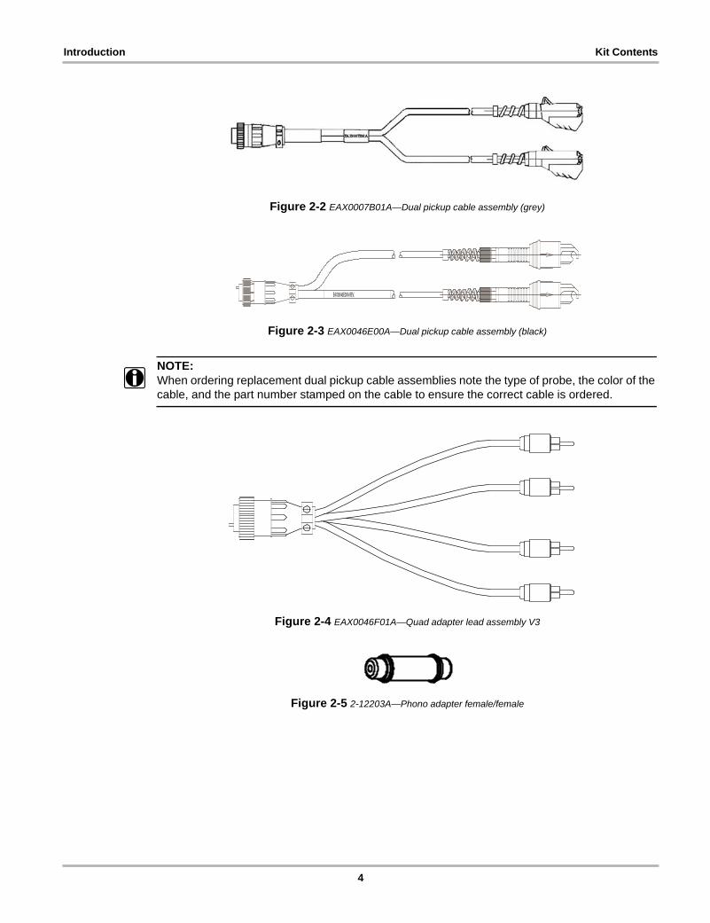
Figure 2-2 EAX0007B01A—Dual pickup cable assembly (grey)
Figure 2-3 EAX0046E00A—Dual pickup cable assembly (black)
NOTE:i When ordering replacement dual pickup cable assemblies note the type of probe, the color of the
cable, and the part number stamped on the cable to ensure the correct cable is ordered.
Figure 2-4 EAX0046F01A—Quad adapter lead assembly V3
Figure 2-5 2-12203A—Phono adapter female/female
EAX0046E00A REV.
4
Introduction Layout
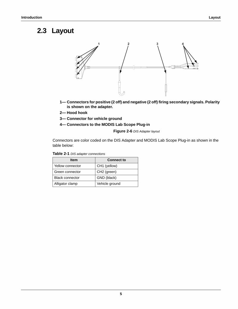
2.3 Layout
1— Connectors for positive (2 off) and negative (2 off) firing secondary signals. Polarity is shown on the adapter.
2— Hood hook3— Connector for vehicle ground4— Connectors to the MODIS Lab Scope Plug-in
Figure 2-6 DIS Adapter layout
Connectors are color coded on the DIS Adapter and MODIS Lab Scope Plug-in as shown in the table below:
Table 2-1 DIS adapter connections
Item Connect toYellow connector CH1 (yellow)
Green connector CH2 (green)
Black connector GND (black)
Alligator clamp Vehicle ground
1 2 3 4
5

Introduction Layout
6
Chapter 3 Getting Started
This chapter describes how to connect the DIS Adapter to the vehicle ignition system and the MODIS Lab Scope Plug-in. Optional pickups may be required.
IMPORTANT:Read and understand the MODIS Lab Scope Plug-in manuals before proceeding.
3.1 Connecting to the Diagnostic ToolPrior to connecting the DIS Adapter to the MODIS Lab Scope Plug-in, check:
• integrity of the wires• integrity of the pins and connectors.
Connect the color-coordinated connectors of the DIS Adapter to the corresponding port on the MODIS Lab Scope Plug-in.
IMPORTANT:Never work with damaged equipment!
3.2 DIS Adapter OperationFor many engines equipped with a distributorless ignition system, the engine configuration information has been included in this manual. Refer to “Coil Information” on page 37.
z To perform tests with the DIS Adapter:1. Prepare the vehicle. Refer to “Preparing the Vehicle” on page 82. Establish the following engine data:
a. Ignition typeb. Number of cylindersc. Firing orderd. Cylinder polaritiese. Cylinder pairs
Wasted Spark specific. A pair of cylinders are cylinders which are connected to the same coil directly.
f. Cylinder firing polarities
7
Getting Started Preparing the Vehicle
Wasted Spark specific. A cylinder pair consists of a negative firing polarity plug and a positive firing polarity plug. To determine the firing polarity. Refer to step 6. on page 8.
3. Connect the DIS Adapter to the MODIS Lab Scope Plug-in and engine ground.4. Depending on the ignition type, use the following components:
– Cable assembly dual pickup, for systems with coil or plug wires.– Quad adaptor lead with coil adaptors, for systems without coil or plug wires.
5. Select the proper view on the MODIS Lab Scope Plug-in.6. Connect the relevant ignition components of all cylinders to the DIS Adapter leads.
Connect one cylinder at a time. Depending on the ignition type, select a lead that is connected to the DIS Adapter, as follows:– Distributor—negative (–) connector– Wasted Spark—negative (–) and positive (+) connectors Refer to “Checking Firing
Polarity” on page 14– Direct—negative (–) connector
7. Connect the trigger lead to cylinder number one, if possible.8. Start the engine and check the ignition signals.
3.3 Preparing the VehicleMake sure you know what the result of the malfunction in the ignition system is. Some results may lead to engine or environmental damage.
If the following conditions are not met, engine damage may occur:
• The engine must have sufficient oil• The engine coolant must be in good condition• The engine must be at normal operating temperature.
3.4 Connecting to Coil and Plug Wires
! WARNINGThe engine compartment contains electrical connections and hot or moving parts.
• Keep yourself, test leads, clothing and other objects clear of electrical connections and hot or moving engine parts.
• Do not wear watches, rings, or loose clothing when working in an engine compartment.• Do not place equipment or tools on fenders or other places in the engine compartment.• Barriers are recommended to help identify danger zones in test area.
Contact with electrical connections and hot or moving parts can cause injury.
If the ignition system uses coil wires that can be accessed, proceed as follows:
1. Connect the cable assembly dual pickup to a negative (–) and/or positive (+) connector of the DIS Adapter. Polarity depends on the ignition type.
2. Connect the clamps to the relevant plug wires.
8
Getting Started Connecting to Coil and Plug Wires
3.4.1 Connecting to Coils or CapsIf no secondary leads are present, use a pickup to receive secondary signals directly from the coil. There are two types of coil pickup:
• coil-specific pickups• generic coil pickups
Contact your sales representative on the availability of pickups.
For some pickups, the phono adaptor provided with the kit may be needed.
3.4.2 Coil PickupsIt is preferred to use coil specific pickups. If these are not available, select a generic coil pickup.
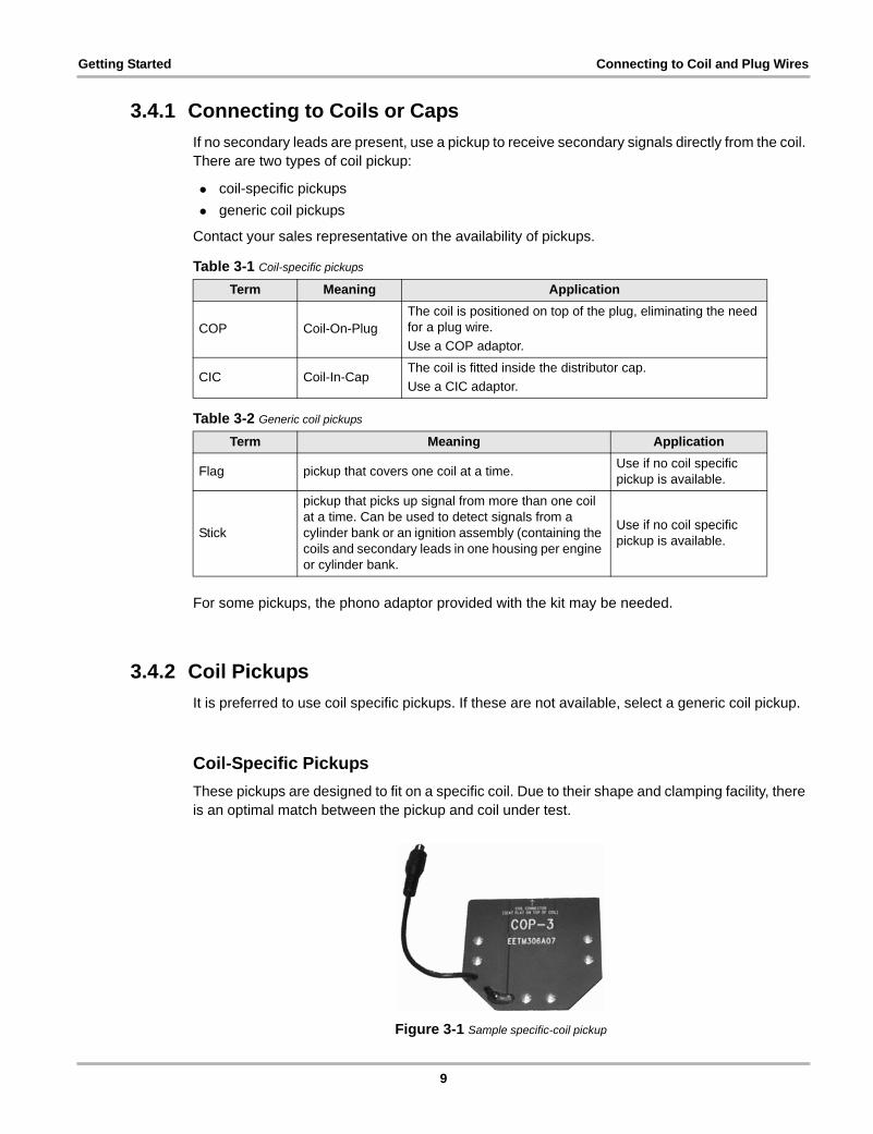
Coil-Specific PickupsThese pickups are designed to fit on a specific coil. Due to their shape and clamping facility, there is an optimal match between the pickup and coil under test.
Figure 3-1 Sample specific-coil pickup
Table 3-1 Coil-specific pickups
Term Meaning Application
COP Coil-On-PlugThe coil is positioned on top of the plug, eliminating the need for a plug wire.Use a COP adaptor.
CIC Coil-In-CapThe coil is fitted inside the distributor cap.Use a CIC adaptor.
Table 3-2 Generic coil pickups
Term Meaning Application
Flag pickup that covers one coil at a time. Use if no coil specific pickup is available.
Stick
pickup that picks up signal from more than one coil at a time. Can be used to detect signals from a cylinder bank or an ignition assembly (containing the coils and secondary leads in one housing per engine or cylinder bank.
Use if no coil specific pickup is available.
9
Getting Started Connecting to Coil and Plug Wires
For an overview, refer to “Coil Adapters” on page 29.
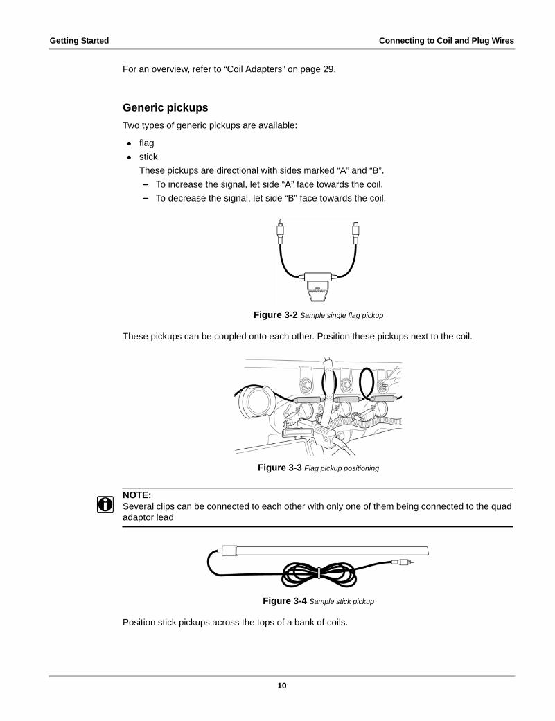
Generic pickupsTwo types of generic pickups are available:
• flag• stick.
These pickups are directional with sides marked “A” and “B”.– To increase the signal, let side “A” face towards the coil.– To decrease the signal, let side “B” face towards the coil.
Figure 3-2 Sample single flag pickup
These pickups can be coupled onto each other. Position these pickups next to the coil.
Figure 3-3 Flag pickup positioning
NOTE:i Several clips can be connected to each other with only one of them being connected to the quad
adaptor lead
Figure 3-4 Sample stick pickup
Position stick pickups across the tops of a bank of coils.
10
Getting Started Connecting to Coil and Plug Wires
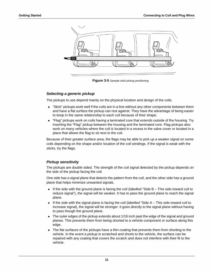
Figure 3-5 Sample stick pickup positioning
Selecting a generic pickupThe pickups to use depend mainly on the physical location and design of the coils.
• “Stick” pickups work well if the coils are in a line without any other components between them and have a flat surface the pickup can rest against. They have the advantage of being easier to keep in the same relationship to each coil because of their shape.
• “Flag” pickups work on coils having a laminated core that extends outside of the housing. Try inserting the “Flag” pickup between the housing and the laminated core. Flag pickups also work on many vehicles where the coil is located in a recess in the valve cover or located in a place that allows the flag to sit next to the coil.
Because of their greater surface area, the flags may be able to pick up a weaker signal on some coils depending on the shape and/or location of the coil windings. If the signal is weak with the sticks, try the flags.
Pickup sensitivityThe pickups are double sided. The strength of the coil signal detected by the pickup depends on the side of the pickup facing the coil.
One side has a signal plane that detects the pattern from the coil, and the other side has a ground plane that helps minimize unwanted signals.
• If the side with the ground plane is facing the coil (labelled “Side B – This side toward coil to reduce signal”), the signal will be weaker. It has to pass the ground plane to reach the signal plane.
• If the side with the signal plane is facing the coil (labelled “Side A – This side toward coil to increase signal), the signal will be stronger. It goes directly to the signal plane without having to pass though the ground plane.
• The outer edges of the pickup extends about 1/16 inch past the edge of the signal and ground planes. This prevents them from being shorted to a vehicle component or surface along this edge.
• The flat surfaces of the pickups have a thin coating that prevents them from shorting to the vehicle. In the event a pickup is scratched and shorts to the vehicle, the surface can be repaired with any coating that covers the scratch and does not interfere with their fit to the vehicle.
11
Getting Started Connecting to Coil and Plug Wires
Positioning Generic PickupsOn an unfamiliar vehicle, you will have to experiment to find the best location for the pickup. The easiest way to do this is by experimenting on a coil. Use the Single Cylinder scope and set the trigger level low to begin with (1-2 kV and 25-50 ms is a good place to start).
z To position a generic pickup:1. Start with “Side B” towards the coil.
This places the pickup with the ground plane facing or nearest to the coil. With the ground plane facing the coil, weaker unwanted signals are not strong enough to make it past the ground plane. The secondary signal is typically strong enough to use the pickup in this manner.
2. Move the pickup around the coil and see where the signal is the strongest and looks the best. You may need to increase the scope trigger level depending on the signal strength for best viewing.As you move the pickup around the coil, you may see the shape of the pattern change. This is likely due to the location of the secondary and primary windings inside of the coil. The pattern tends to portray the windings closest to the pickup.
3. If the signal level is not strong enough, try Side A facing the coil. This places the signal plane closest to the coil giving the strongest signal.
NOTE:i On some coils, the pattern looks like a conventional secondary pattern. On others, there may be
much less detail.
NOTE:i On some coils you will note a large difference in the pattern depending on the exact location of the
pickup in relation to the coil. Pick the spot that gives the best pattern and allows the pickup to “stay put” (otherwise improvise to hold the pickup in the desired place).
NOTE:i Each pickup should be located in the same position on each coil, so the signal is the same from
each one.
3.4.3 Connecting to Ignition SystemsAlways proceed in the following order:
1. Determine the required vehicle information. Refer to “Preparing the Vehicle” on page 82. Connect the relevant ignition components that are to be connected to the DIS Adapter.3. Connect the trigger clamp to cylinder #1 if applicable.4. Adjust the application settings, if required.
A wide variety of ignition systems and configurations is available on the market. Some systems allow for more than one way of obtaining an ignition signal.
The following list may not contain all possible ignition system configurations, due to constant improvement of the automotive technology.
12
Getting Started Connecting to Coil and Plug Wires
DistributorThis section describes ignition systems that use one or more distributors.
Conventional Ignition SystemsThese systems have an external coil, a high tension lead, a distributor and plug wires.
z To connect a conventional system:1. Connect one or more cable assembly dual pickups to a negative (–) connector of the
DIS Adapter2. Connect a pickup to the coil wire.
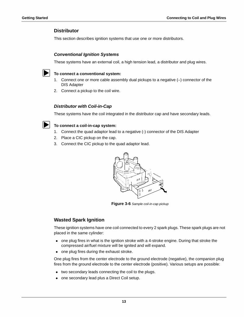
Distributor with Coil-in-CapThese systems have the coil integrated in the distributor cap and have secondary leads.
z To connect a coil-in-cap system:1. Connect the quad adaptor lead to a negative (-) connector of the DIS Adapter2. Place a CIC pickup on the cap.3. Connect the CIC pickup to the quad adaptor lead.
Figure 3-6 Sample coil-in-cap pickup
Wasted Spark IgnitionThese ignition systems have one coil connected to every 2 spark plugs. These spark plugs are not placed in the same cylinder:
• one plug fires in what is the ignition stroke with a 4-stroke engine. During that stroke the compressed air/fuel mixture will be ignited and will expand.
• one plug fires during the exhaust stroke.
One plug fires from the center electrode to the ground electrode (negative), the companion plug fires from the ground electrode to the center electrode (positive). Various setups are possible:
• two secondary leads connecting the coil to the plugs.• one secondary lead plus a Direct Coil setup.
13
Getting Started Connecting to Coil and Plug Wires
z To test wasted spark ignition systems:1. Connect an appropriate adaptor (cable assembly dual pickup or a coil specific pickup via the
quad adaptor lead) to a cylinder and connect it to the DIS Adapter. Refer to “Checking Firing Polarity” on page 14.
2. Connect an appropriate adaptor, from another Assembly or Lead (cable assembly dual pickup or a coil specific pickup via the quad adaptor lead) to the companion of the cylinder mentioned before. Now connect the other Assembly or Lead to a connector of the DIS Adapter with a different polarity.
3. Repeat previous steps to connect all plugs.
NOTE:i Always check the polarity. Different engines may have a different setup.
Checking Firing PolarityOnly with wasted spark ignition systems, positive and negative firing polarities are possible.
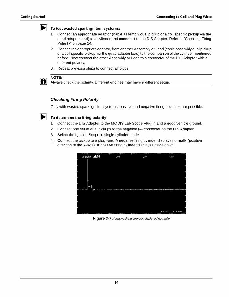
z To determine the firing polarity:1. Connect the DIS Adapter to the MODIS Lab Scope Plug-in and a good vehicle ground.2. Connect one set of dual pickups to the negative (–) connector on the DIS Adapter.3. Select the Ignition Scope in single cylinder mode.4. Connect the pickup to a plug wire. A negative firing cylinder displays normally (positive
direction of the Y-axis). A positive firing cylinder displays upside down.
Figure 3-7 Negative firing cylinder, displayed normally
14
Getting Started Connecting to Coil and Plug Wires
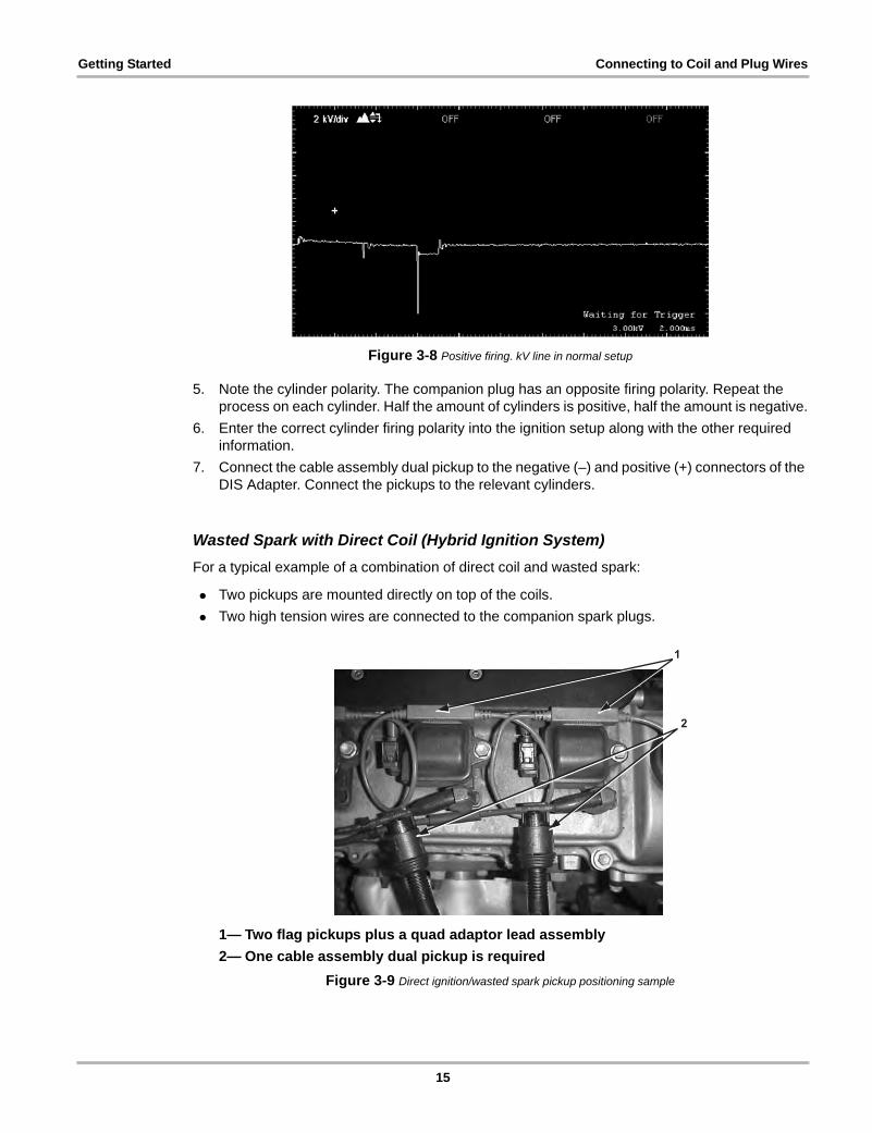
Figure 3-8 Positive firing. kV line in normal setup
5. Note the cylinder polarity. The companion plug has an opposite firing polarity. Repeat the process on each cylinder. Half the amount of cylinders is positive, half the amount is negative.
6. Enter the correct cylinder firing polarity into the ignition setup along with the other required information.
7. Connect the cable assembly dual pickup to the negative (–) and positive (+) connectors of the DIS Adapter. Connect the pickups to the relevant cylinders.
Wasted Spark with Direct Coil (Hybrid Ignition System)For a typical example of a combination of direct coil and wasted spark:
• Two pickups are mounted directly on top of the coils.• Two high tension wires are connected to the companion spark plugs.
1— Two flag pickups plus a quad adaptor lead assembly2— One cable assembly dual pickup is required
Figure 3-9 Direct ignition/wasted spark pickup positioning sample
1
2
15
Getting Started Connecting to Coil and Plug Wires
NOTE:i Not every hybrid ignition system supplies good, clear signals easily. The location of the generic
pickup in the figure is an example of one possible location for the pickup. You may need to make several attempts. Refer to “Positioning Generic Pickups” on page 12.
NOTE:i Sometimes it is not possible to pick up the ignition pattern from the cylinder of which only the coil
is accessible. If that happens, insert a plug wire between the coil and the plug. The ignition system can then be tested like a standard wasted spark ignition system with 2 wires on each coil.
Direct Ignition SystemsDirect ignition systems use one coil for every spark plug. The coil may be mounted directly onto the spark plug, thus eliminating the plug wire. Or the coil may be remotely mounted from the spark plug, requiring a plug wire.
Another setup is a distributorless ignition system with plug wires positioned in an ignition assembly that is not supposed to be opened. Such an assembly is fitted directly on top of the plugs.
To test, connect a coil specific pickup (preferred) or a generic pickup via the quad adaptor lead to a negative (–) connector of the DIS Adapter.
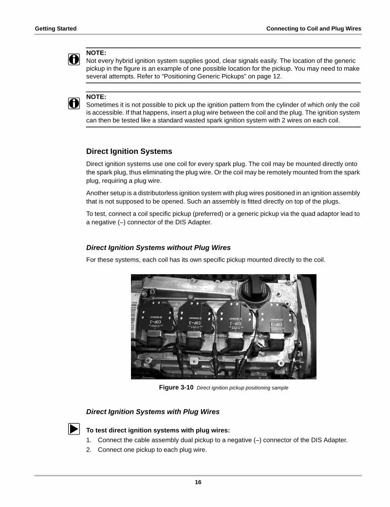
Direct Ignition Systems without Plug WiresFor these systems, each coil has its own specific pickup mounted directly to the coil.
Figure 3-10 Direct ignition pickup positioning sample
Direct Ignition Systems with Plug Wires
z To test direct ignition systems with plug wires:1. Connect the cable assembly dual pickup to a negative (–) connector of the DIS Adapter.2. Connect one pickup to each plug wire.
16
Chapter 4 Operation
After preparing the vehicle, DIS Adapter and the MODIS Lab Scope Plug-in for operation, the ignition waveforms should appear on the screen. Due to a variety of technologies and constructions used by vehicle manufacturers and after market suppliers, experience with testing on “good” and “bad” ignition systems will give the operator better insight and confidence in the interpretation of test results.
4.1 Interpreting test resultsA secondary ignition waveform appears on the screen.
• Waveforms collected with the DIS Adapter can be analyzed like all other conventional secondary ignition waveforms.– The higher the spark voltage, the shorter the duration; the lower the spark voltage, the
longer the duration.– Relative measurements are more important than absolute values. Compare cylinders to
each other and look for noticeable differences.• The “Firing kV” values on Direct Ignition and Wasted Spark ignition systems may vary more
than on conventional distributor systems. This variation, in itself, does not indicate a problem.Examine both the spark voltage and burn time (duration).
• Many coils have diodes in the secondary circuit and the secondary resistance of these coils can not be measured. Refer to manufacturer specifications for information about these coils.
• Coil oscillations on coil-on-plug systems may be lower than coil oscillations of previous (‘conventional’) systems. In some cases normal oscillations may be as low as zero. Compare each vehicle coil with others on the vehicle to identify a coil with a different characteristic.
• Check the spark line on all cylinders. Suspect any that are smooth, less turbulent, or with a different slope. Sparks that occur outside the combustion chamber are typically more stable than sparks that occur in the combustion chamber.
4.2 TroubleshootingThis section addresses common problems with triggering and unstable patterns that may occur when testing with the DIS Adapter.
For problems at any engine speed, including cranking:
• Check all lead connections.• Check for correct positioning of all pickups.
– Pickups must contact each coil identically for consistent test results.– Generic pickups are directional with sides marked “A” and “B”. Turn over the pickup to
change the sensitivity.• Check all tester ground connections.
17
Operation Troubleshooting
NOTE:i Because spark duration and voltage are related, any system problem that affects one, affects the
other as well.
• If spark voltage increases, spark duration decreases.• If spark voltage decreases, spark duration increases.
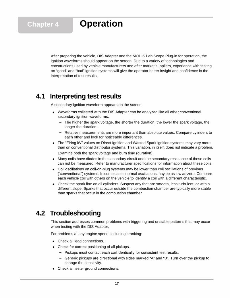
4.2.1 Polarity IssuesMost of the vehicles have a negative firing setup. Plugs fire from the center electrode to the side or ground electrode.
Figure 4-1 Negative firing. kV line in normal setup
With a positive firing setup, the plug fires from the side or ground electrode to the center electrode.
Figure 4-2 Positive firing. kV line in normal setup
Refer to “DIS Adapter Operation” on page 7 for more information.
18
Operation Troubleshooting
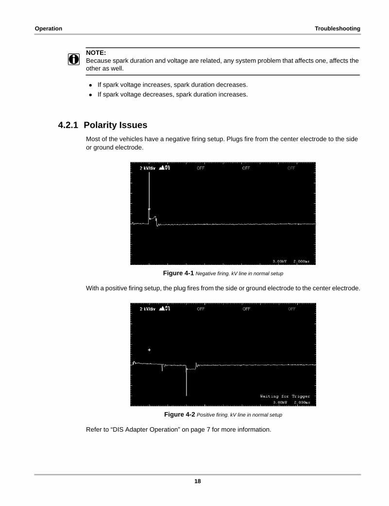
4.2.2 Wasted Spark SystemsThis section gives an example of a “good” wasted spark system pattern and several “faulty” system patterns with explanations.
Normal Pattern
Figure 4-3 Normal pattern
All settings and connections are correct. Power firings are on channel 1. The wasted spark firings are on channel 2.
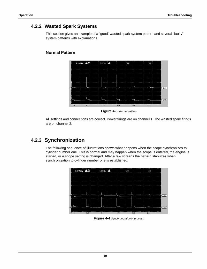
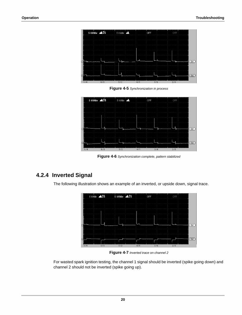
4.2.3 SynchronizationThe following sequence of illustrations shows what happens when the scope synchronizes to cylinder number one. This is normal and may happen when the scope is entered, the engine is started, or a scope setting is changed. After a few screens the pattern stabilizes when synchronization to cylinder number one is established.
Figure 4-4 Synchronization in process
19
Operation Troubleshooting
Figure 4-5 Synchronization in process
Figure 4-6 Synchronization complete, pattern stabilized
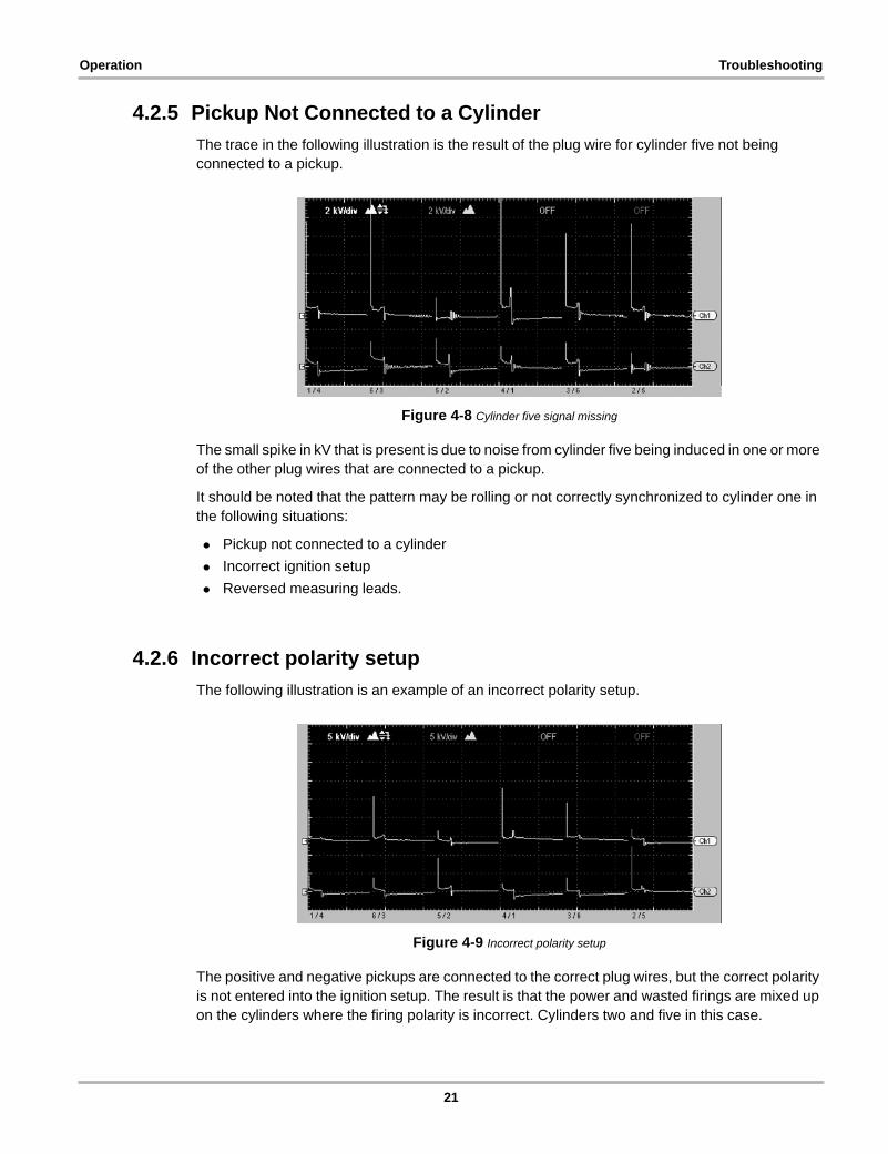
4.2.4 Inverted SignalThe following illustration shows an example of an inverted, or upside down, signal trace.
Figure 4-7 Inverted trace on channel 2
For wasted spark ignition testing, the channel 1 signal should be inverted (spike going down) and channel 2 should not be inverted (spike going up).
20
Operation Troubleshooting
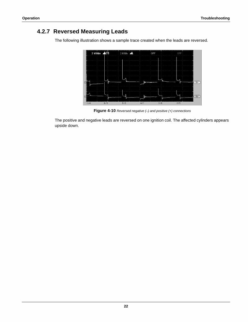
4.2.5 Pickup Not Connected to a CylinderThe trace in the following illustration is the result of the plug wire for cylinder five not being connected to a pickup.
Figure 4-8 Cylinder five signal missing
The small spike in kV that is present is due to noise from cylinder five being induced in one or more of the other plug wires that are connected to a pickup.
It should be noted that the pattern may be rolling or not correctly synchronized to cylinder one in the following situations:
• Pickup not connected to a cylinder• Incorrect ignition setup• Reversed measuring leads.
4.2.6 Incorrect polarity setupThe following illustration is an example of an incorrect polarity setup.
Figure 4-9 Incorrect polarity setup
The positive and negative pickups are connected to the correct plug wires, but the correct polarity is not entered into the ignition setup. The result is that the power and wasted firings are mixed up on the cylinders where the firing polarity is incorrect. Cylinders two and five in this case.
21
Operation Troubleshooting
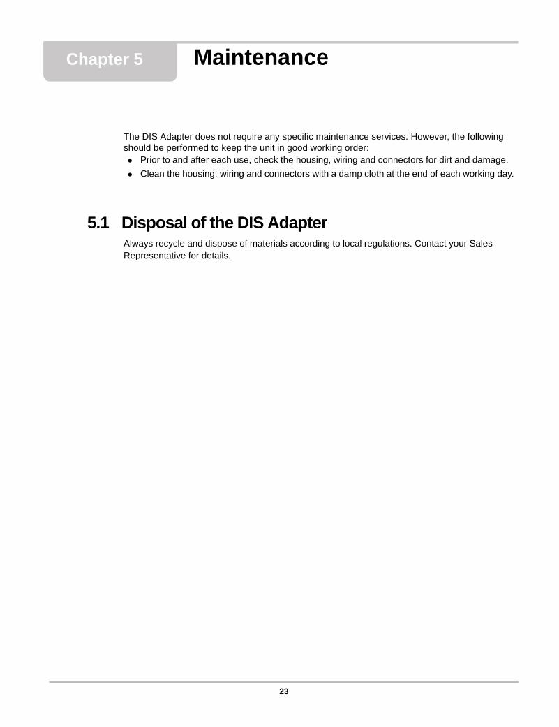
4.2.7 Reversed Measuring LeadsThe following illustration shows a sample trace created when the leads are reversed.
Figure 4-10 Reversed negative (–) and positive (+) connections
The positive and negative leads are reversed on one ignition coil. The affected cylinders appears upside down.
22
Chapter 5 Maintenance
The DIS Adapter does not require any specific maintenance services. However, the following should be performed to keep the unit in good working order:• Prior to and after each use, check the housing, wiring and connectors for dirt and damage.• Clean the housing, wiring and connectors with a damp cloth at the end of each working day.
5.1 Disposal of the DIS AdapterAlways recycle and dispose of materials according to local regulations. Contact your Sales Representative for details.
23

Maintenance Disposal of the DIS Adapter
24
Appendix A Ignition Waveforms
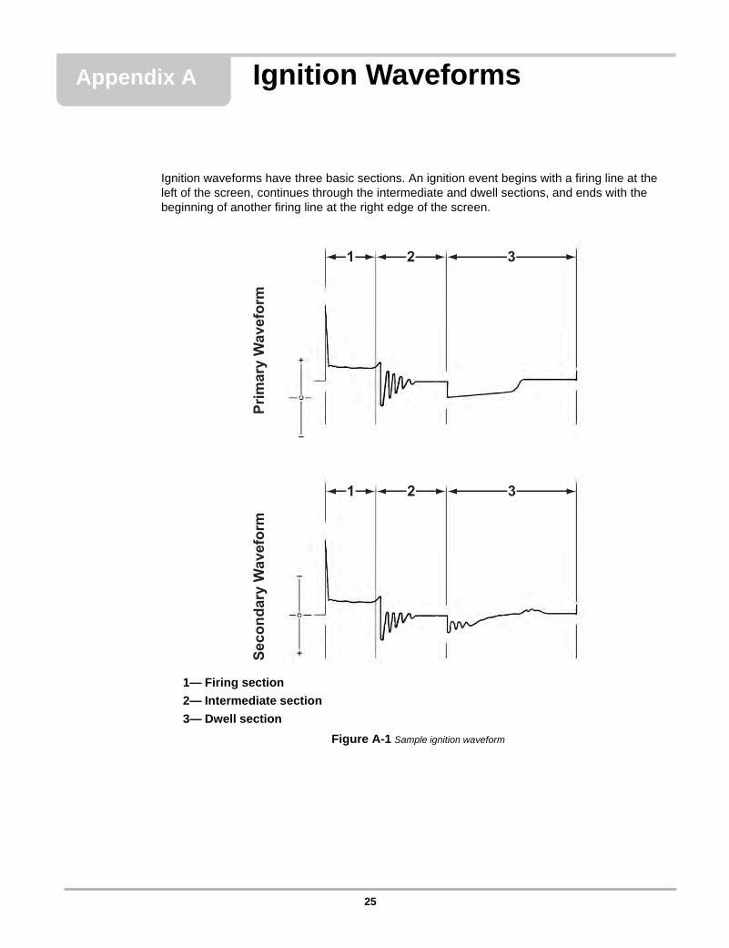
Ignition waveforms have three basic sections. An ignition event begins with a firing line at the left of the screen, continues through the intermediate and dwell sections, and ends with the beginning of another firing line at the right edge of the screen.
1— Firing section2— Intermediate section3— Dwell section
Figure A-1 Sample ignition waveform
1 2 3
1 2 3Pr
imar
yW
avef
orm
Seco
ndar
yW
avef
orm
25
Ignition Waveforms The Ignition Cycle
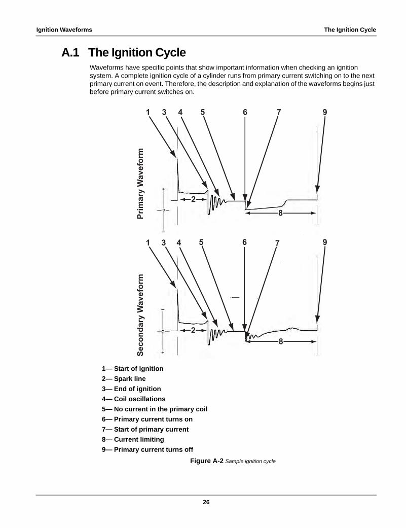
A.1 The Ignition CycleWaveforms have specific points that show important information when checking an ignition system. A complete ignition cycle of a cylinder runs from primary current switching on to the next primary current on event. Therefore, the description and explanation of the waveforms begins just before primary current switches on.
1— Start of ignition2— Spark line3— End of ignition4— Coil oscillations5— No current in the primary coil6— Primary current turns on7— Start of primary current8— Current limiting9— Primary current turns off
Figure A-2 Sample ignition cycle
28
28
Prim
ary
Wav
efor
mSe
cond
ary
Wav
efor
m
1 3 4 5 6 7 9
1 3 4 5 6 7 9
26
Ignition Waveforms The Ignition Cycle
Start of IgnitionHigh voltage is induced, by mutual induction, into the secondary winding because of the primary to secondary turns ratio. The secondary voltage overcomes the resistance in the secondary circuit up to the spark plug gap. The spark plug gap is ionized and current arcs across the electrodes to produce the spark that initiates combustion.
Spark LineVoltage is reduced to about 1/100th of the secondary voltage, because of the 100:1 step-down ratio. This is the actual discharge across the air gap between the spark plug electrodes.
End of IgnitionThe coil energy is no longer able to sustain the spark across the electrodes at this point.
Coil OscillationsAn oscillating voltage results (in step with the secondary voltage) because of the step-down ratio as current dissipates in the primary circuit.
No Current in the Primary CoilThe trace flattens out when there is no longer current in the primary ignition circuit. Battery or charging system voltage available at this point is about 12 to 15 volts.
Primary Current Turns OnThe primary circuit switching device switches on the primary current. This starts the dwell period.
Start of Primary Current Current in the primary circuit establishes a magnetic field in the ignition coil windings. The strength of the field builds during the dwell period.
27
Ignition Waveforms The Ignition Cycle
Current LimitingThis represents the dwell period or “on-time” of the ignition coil primary current:
• The rise in voltage (primary waveform) indicates that current limiting is occurring.• On ignition systems that use current limiting to control the coil current, a current hump or
voltage ripple appears on the “on-time” portion of the primary waveform during the dwell section.
Primary Current Turns OffThe primary switching device stops the primary current flow suddenly. The magnetic field that had built up collapses. This induces a high voltage in the primary winding by self-induction.
28
Appendix B Coil Adapters
This section shows an overview of adaptors that are available for testing distributorless ignition systems. Contact your sales representative for additional information. There are two types of coil adapters:
• Coil-in-cap (CIC) • Coil-on-plug (COP)
B.1 Coil-in-cap AdaptersCoil-in-cap (CIC) adapters are used for testing systems that have a conventional distributor with the ignition coil integrated into the distributor cap.
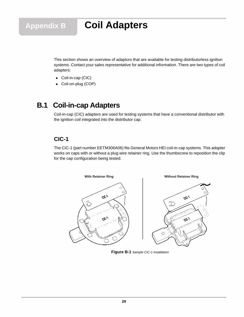
CIC-1The CIC-1 (part number EETM306A06) fits General Motors HEI coil-in-cap systems. This adapter works on caps with or without a plug wire retainer ring. Use the thumbscrew to reposition the clip for the cap configuration being tested.
Figure B-1 Sample CIC-1 installation
With Retainer Ring Without Retainer Ring
29
Coil Adapters Coil-on-plug Adapters
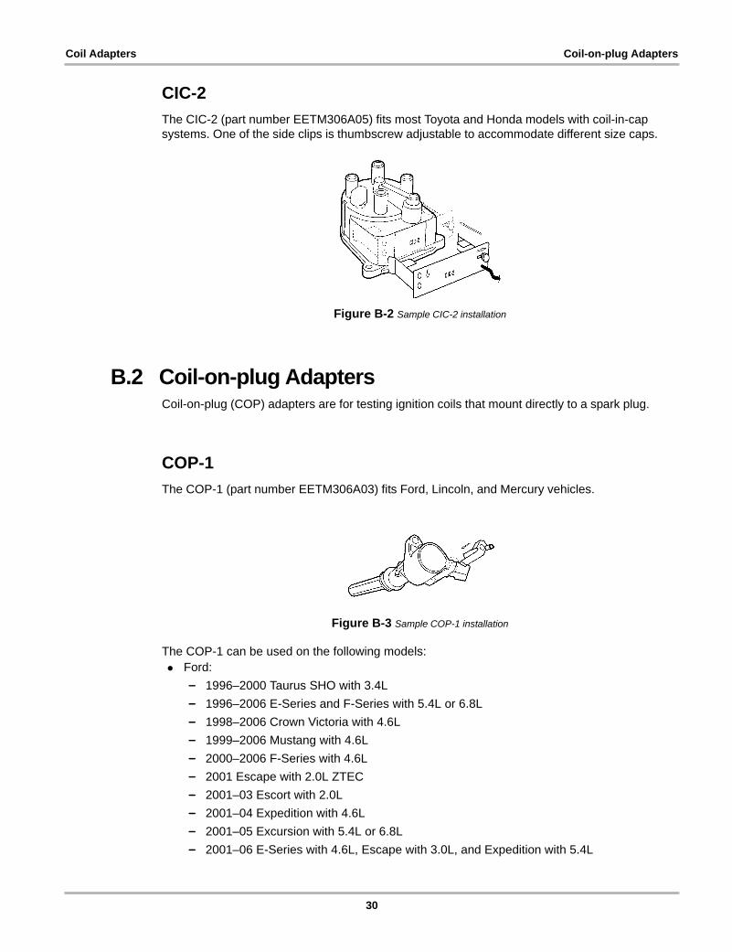
CIC-2The CIC-2 (part number EETM306A05) fits most Toyota and Honda models with coil-in-cap systems. One of the side clips is thumbscrew adjustable to accommodate different size caps.
Figure B-2 Sample CIC-2 installation
B.2 Coil-on-plug AdaptersCoil-on-plug (COP) adapters are for testing ignition coils that mount directly to a spark plug.
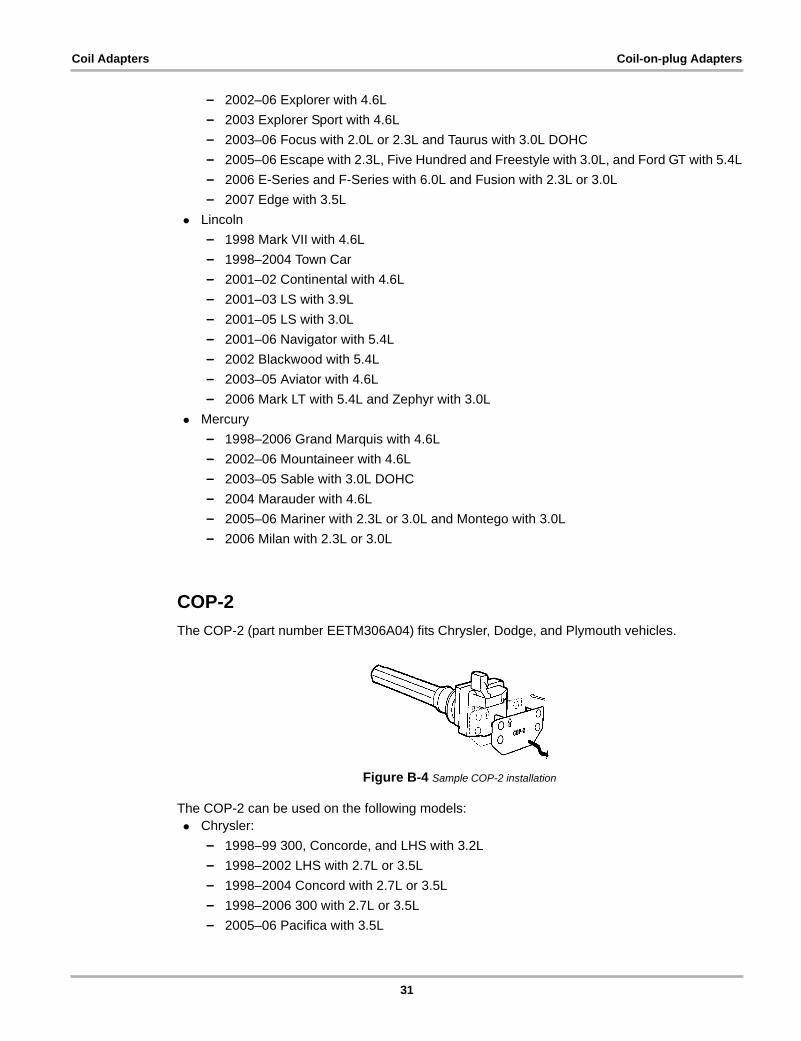
COP-1The COP-1 (part number EETM306A03) fits Ford, Lincoln, and Mercury vehicles.
Figure B-3 Sample COP-1 installation
The COP-1 can be used on the following models:• Ford:
– 1996–2000 Taurus SHO with 3.4L– 1996–2006 E-Series and F-Series with 5.4L or 6.8L– 1998–2006 Crown Victoria with 4.6L– 1999–2006 Mustang with 4.6L– 2000–2006 F-Series with 4.6L– 2001 Escape with 2.0L ZTEC– 2001–03 Escort with 2.0L– 2001–04 Expedition with 4.6L– 2001–05 Excursion with 5.4L or 6.8L– 2001–06 E-Series with 4.6L, Escape with 3.0L, and Expedition with 5.4L
30
Coil Adapters Coil-on-plug Adapters
– 2002–06 Explorer with 4.6L– 2003 Explorer Sport with 4.6L– 2003–06 Focus with 2.0L or 2.3L and Taurus with 3.0L DOHC– 2005–06 Escape with 2.3L, Five Hundred and Freestyle with 3.0L, and Ford GT with 5.4L– 2006 E-Series and F-Series with 6.0L and Fusion with 2.3L or 3.0L– 2007 Edge with 3.5L
• Lincoln– 1998 Mark VII with 4.6L– 1998–2004 Town Car– 2001–02 Continental with 4.6L– 2001–03 LS with 3.9L– 2001–05 LS with 3.0L– 2001–06 Navigator with 5.4L– 2002 Blackwood with 5.4L– 2003–05 Aviator with 4.6L– 2006 Mark LT with 5.4L and Zephyr with 3.0L
• Mercury– 1998–2006 Grand Marquis with 4.6L– 2002–06 Mountaineer with 4.6L– 2003–05 Sable with 3.0L DOHC– 2004 Marauder with 4.6L– 2005–06 Mariner with 2.3L or 3.0L and Montego with 3.0L– 2006 Milan with 2.3L or 3.0L
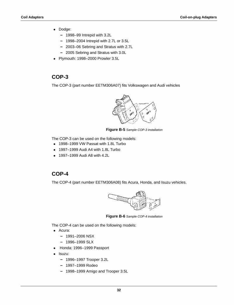
COP-2The COP-2 (part number EETM306A04) fits Chrysler, Dodge, and Plymouth vehicles.
Figure B-4 Sample COP-2 installation
The COP-2 can be used on the following models:• Chrysler:
– 1998–99 300, Concorde, and LHS with 3.2L– 1998–2002 LHS with 2.7L or 3.5L– 1998–2004 Concord with 2.7L or 3.5L– 1998–2006 300 with 2.7L or 3.5L– 2005–06 Pacifica with 3.5L
31
Coil Adapters Coil-on-plug Adapters
• Dodge:– 1998–99 Intrepid with 3.2L– 1998–2004 Intrepid with 2.7L or 3.5L– 2003–06 Sebring and Stratus with 2.7L– 2005 Sebring and Stratus with 3.0L
• Plymouth: 1998–2000 Prowler 3.5L
COP-3The COP-3 (part number EETM306A07) fits Volkswagen and Audi vehicles
Figure B-5 Sample COP-3 installation
The COP-3 can be used on the following models:• 1998–1999 VW Passat with 1.8L Turbo• 1997–1999 Audi A4 with 1.8L Turbo• 1997–1999 Audi A8 with 4.2L
COP-4The COP-4 (part number EETM306A08) fits Acura, Honda, and Isuzu vehicles.
Figure B-6 Sample COP-4 installation
The COP-4 can be used on the following models:• Acura:
– 1991–2006 NSX– 1996–1999 SLX
• Honda: 1996–1999 Passport• Isuzu:
– 1996–1997 Trooper 3.2L– 1997–1999 Rodeo– 1998–1999 Amigo and Trooper 3.5L
32
Coil Adapters Coil-on-plug Adapters
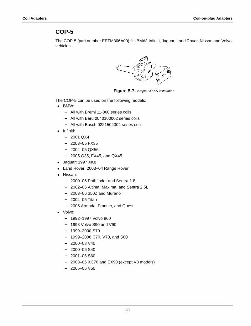
COP-5The COP-5 (part number EETM306A09) fits BMW, Infiniti, Jaguar, Land Rover, Nissan and Volvo vehicles.
Figure B-7 Sample COP-5 installation
The COP-5 can be used on the following models:• BMW:
– All with Bremi 11-860 series coils– All with Beru 0040100002 series coils– All with Bosch 0221504004 series coils
• Infiniti:– 2001 QX4– 2003–05 FX35– 2004–05 QX56– 2005 G35, FX45, and QX45
• Jaguar: 1997 XK8• Land Rover: 2003–04 Range Rover• Nissan:
– 2000–06 Pathfinder and Sentra 1.8L– 2002–06 Altima, Maxima, and Sentra 2.5L– 2003–06 350Z and Murano– 2004–06 Titan– 2005 Armada, Frontier, and Quest
• Volvo:– 1992–1997 Volvo 960– 1998 Volvo S90 and V90– 1999–2000 S70– 1999–2006 C70, V70, and S80– 2000–03 V40– 2000–06 S40– 2001–06 S60– 2003–06 XC70 and EX90 (except V8 models)– 2005–06 V50
33
Coil Adapters Coil-on-plug Adapters
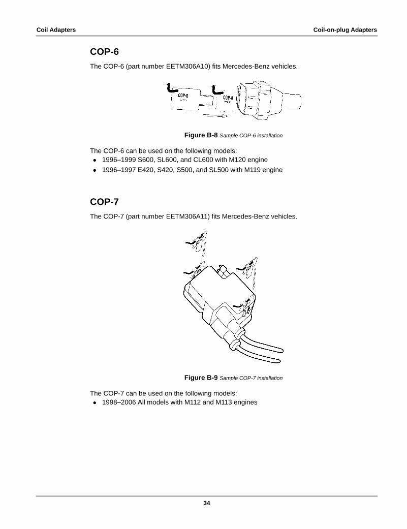
COP-6The COP-6 (part number EETM306A10) fits Mercedes-Benz vehicles.
Figure B-8 Sample COP-6 installation
The COP-6 can be used on the following models:• 1996–1999 S600, SL600, and CL600 with M120 engine• 1996–1997 E420, S420, S500, and SL500 with M119 engine
COP-7The COP-7 (part number EETM306A11) fits Mercedes-Benz vehicles.
Figure B-9 Sample COP-7 installation
The COP-7 can be used on the following models:• 1998–2006 All models with M112 and M113 engines
34
Coil Adapters Coil-on-plug Adapters
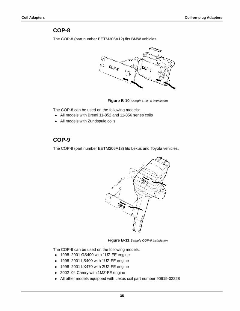
COP-8The COP-8 (part number EETM306A12) fits BMW vehicles.
Figure B-10 Sample COP-8 installation
The COP-8 can be used on the following models:• All models with Bremi 11-852 and 11-856 series coils• All models with Zundspule coils
COP-9The COP-9 (part number EETM306A13) fits Lexus and Toyota vehicles.
Figure B-11 Sample COP-9 installation
The COP-9 can be used on the following models:• 1998–2001 GS400 with 1UZ-FE engine• 1998–2001 LS400 with 1UZ-FE engine• 1998–2001 LX470 with 2UZ-FE engine• 2002–04 Camry with 1MZ-FE engine• All other models equipped with Lexus coil part number 90919-02228
35
Coil Adapters Coil-on-plug Adapters
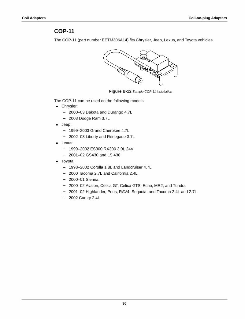
COP-11The COP-11 (part number EETM306A14) fits Chrysler, Jeep, Lexus, and Toyota vehicles.
Figure B-12 Sample COP-11 installation
The COP-11 can be used on the following models:• Chrysler:
– 2000–03 Dakota and Durango 4.7L– 2003 Dodge Ram 3.7L
• Jeep:– 1999–2003 Grand Cherokee 4.7L– 2002–03 Liberty and Renegade 3.7L
• Lexus:– 1999–2002 ES300 RX300 3.0L 24V– 2001–02 GS430 and LS 430
• Toyota:– 1998–2002 Corolla 1.8L and Landcruiser 4.7L– 2000 Tacoma 2.7L and California 2.4L– 2000–01 Sienna– 2000–02 Avalon, Celica GT, Celica GTS, Echo, MR2, and Tundra– 2001–02 Highlander, Prius, RAV4, Sequoia, and Tacoma 2.4L and 2.7L– 2002 Camry 2.4L
36
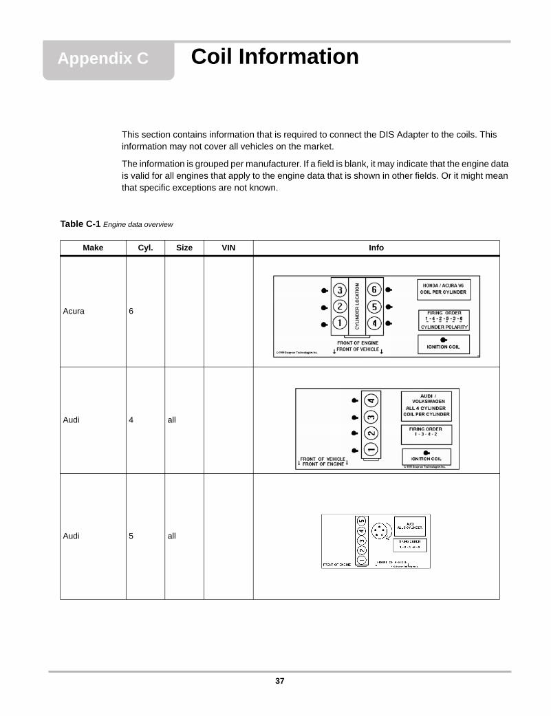
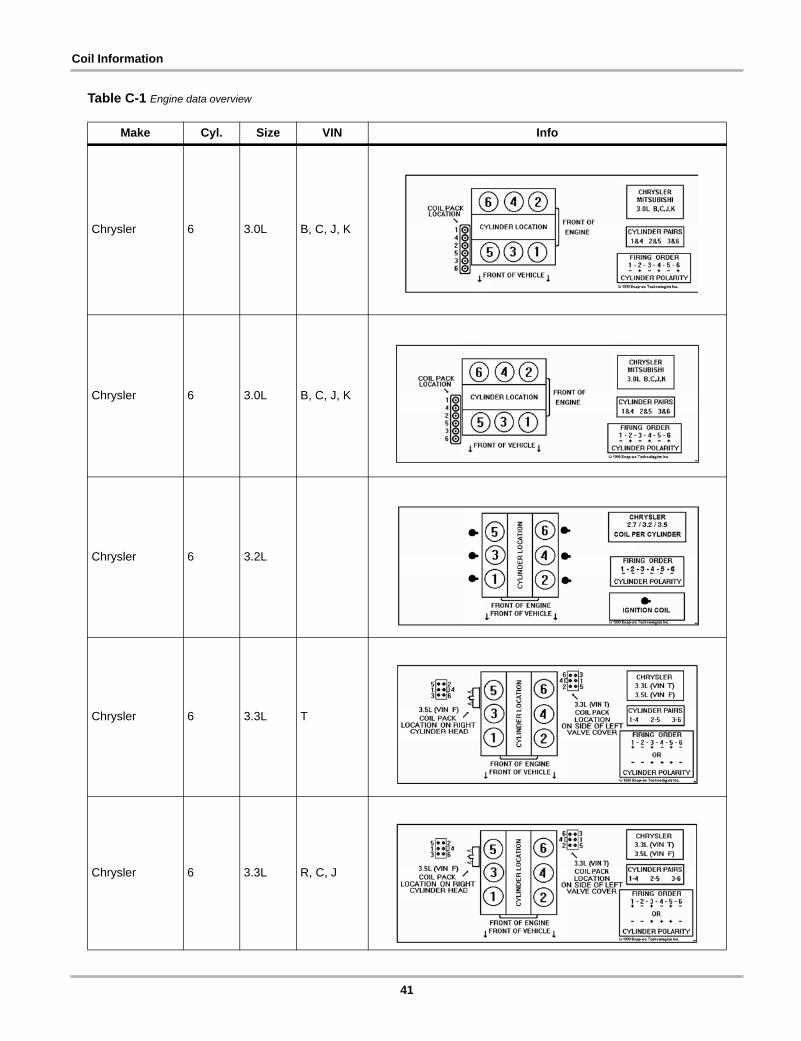
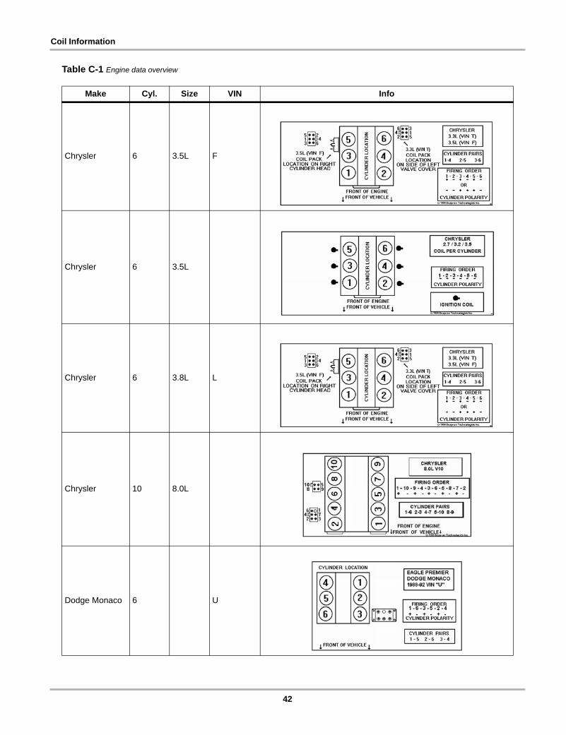
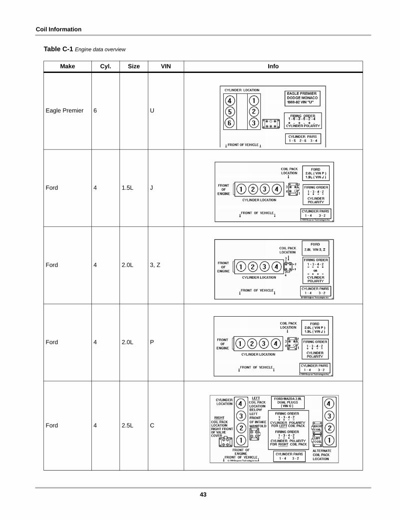
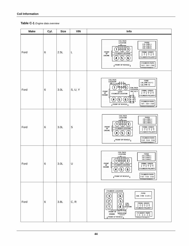
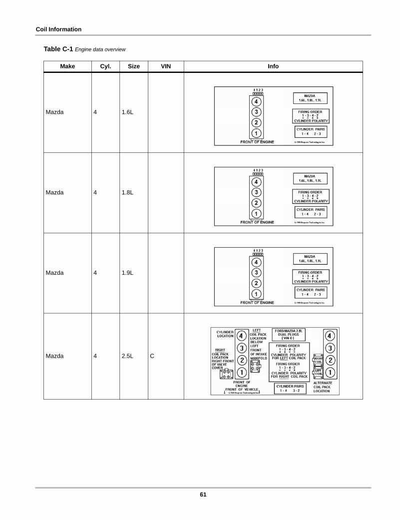
Appendix C Coil Information
This section contains information that is required to connect the DIS Adapter to the coils. This information may not cover all vehicles on the market.
The information is grouped per manufacturer. If a field is blank, it may indicate that the engine data is valid for all engines that apply to the engine data that is shown in other fields. Or it might mean that specific exceptions are not known.
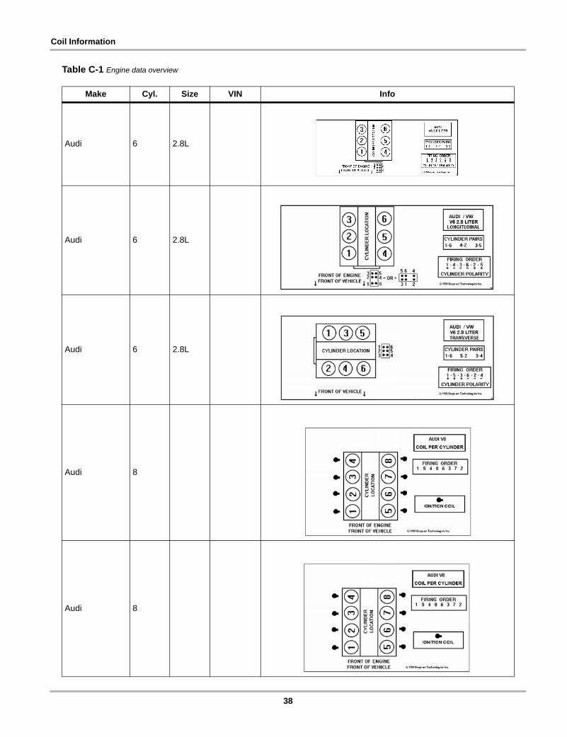
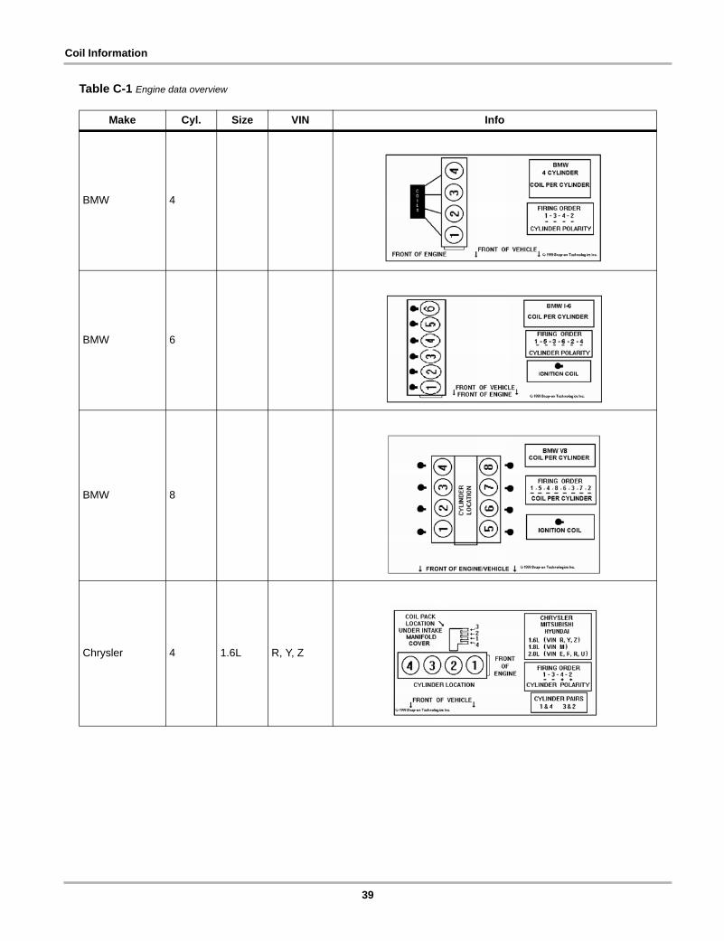
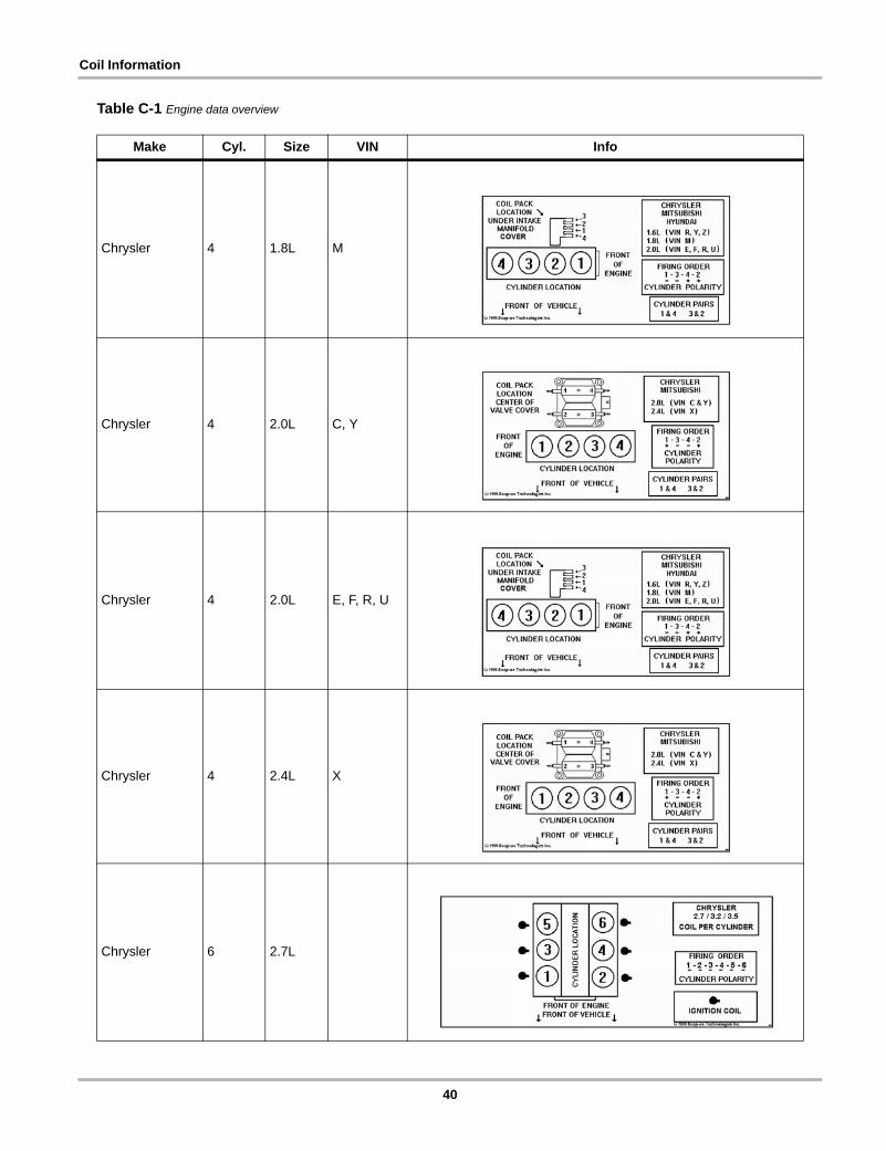
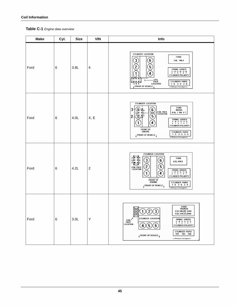
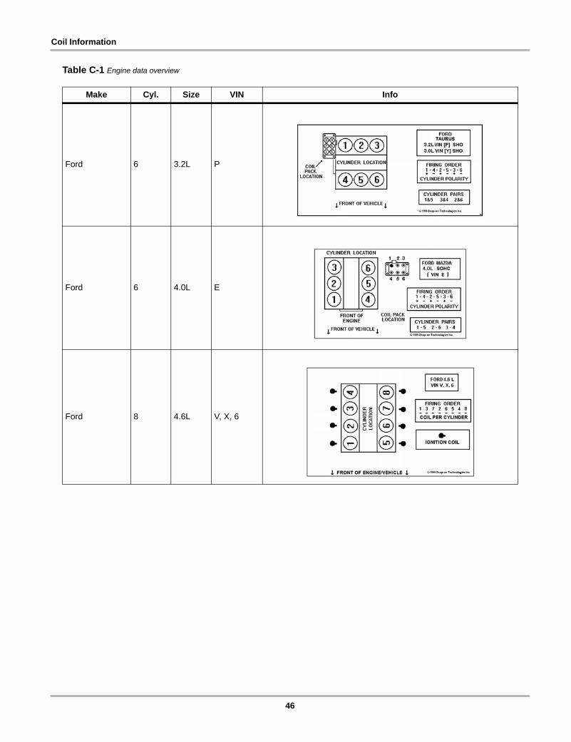
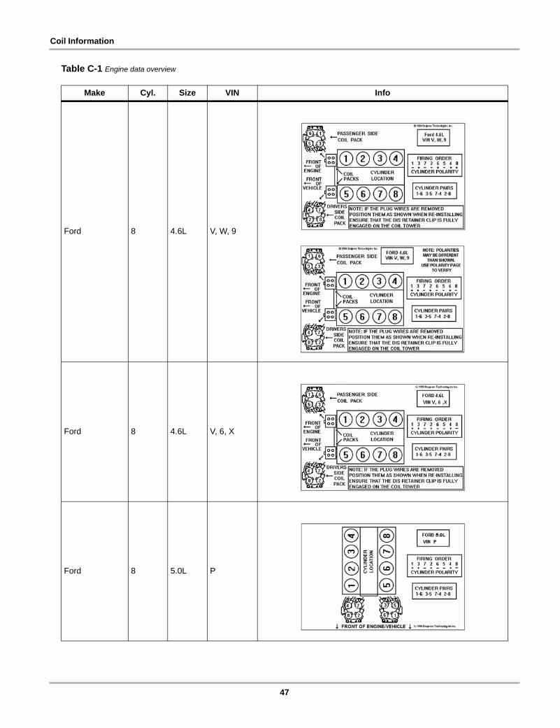
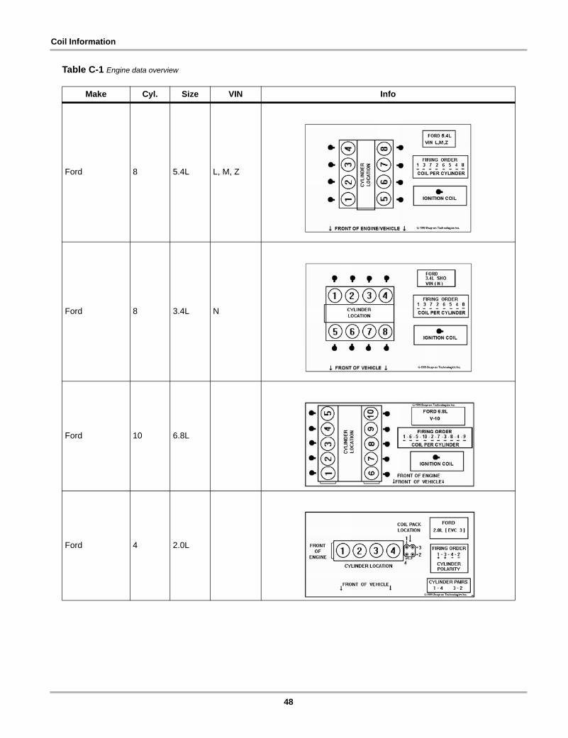
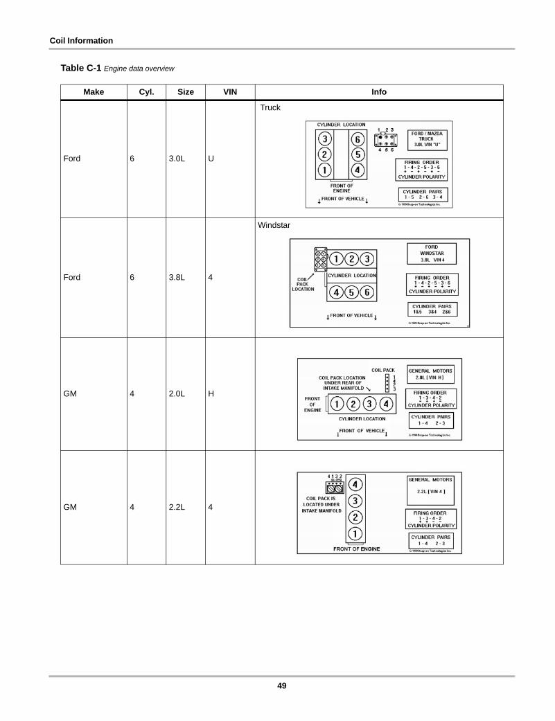
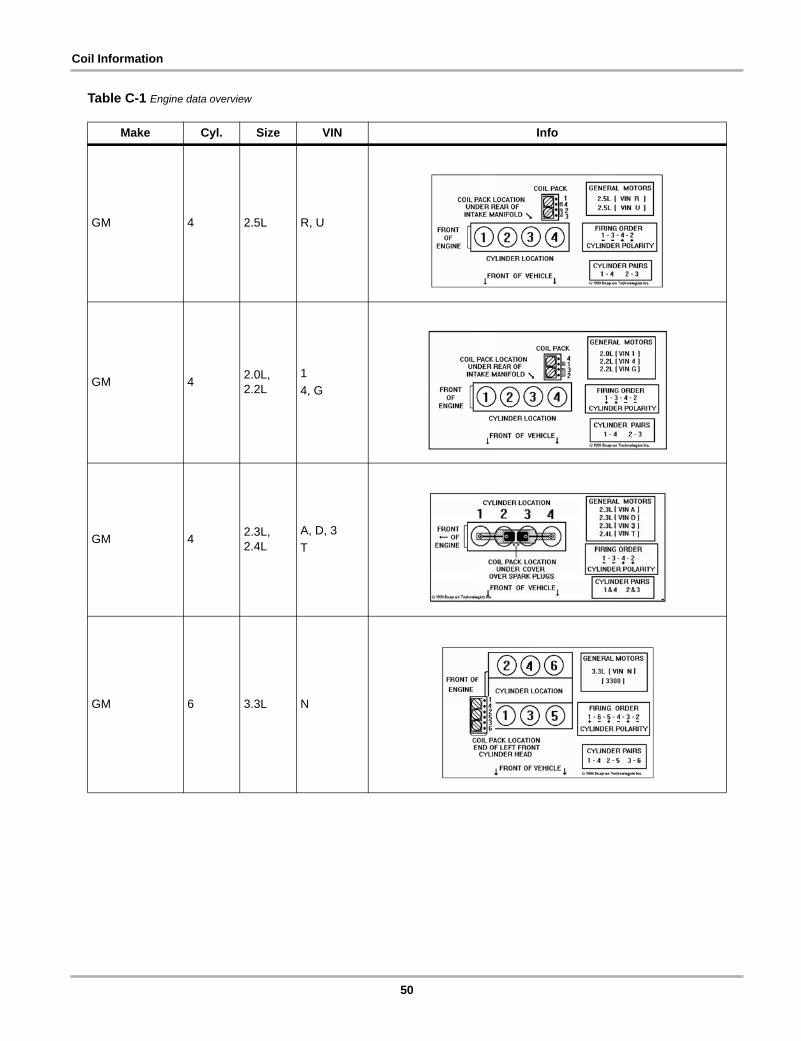
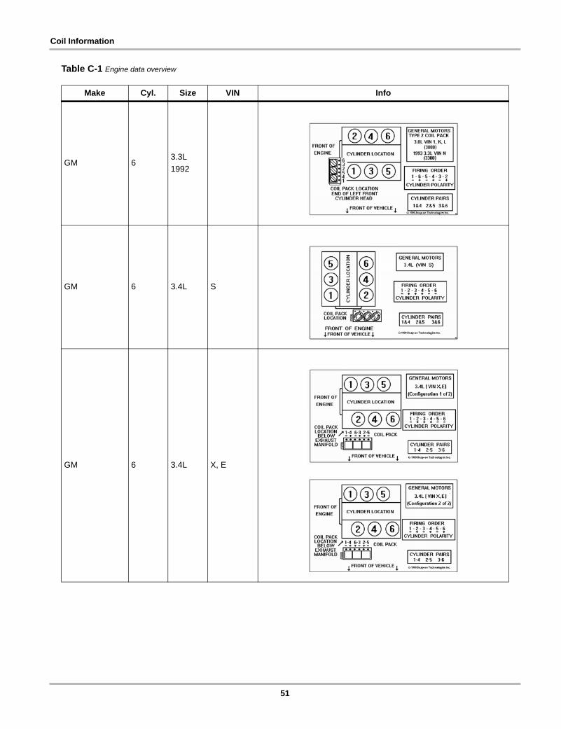
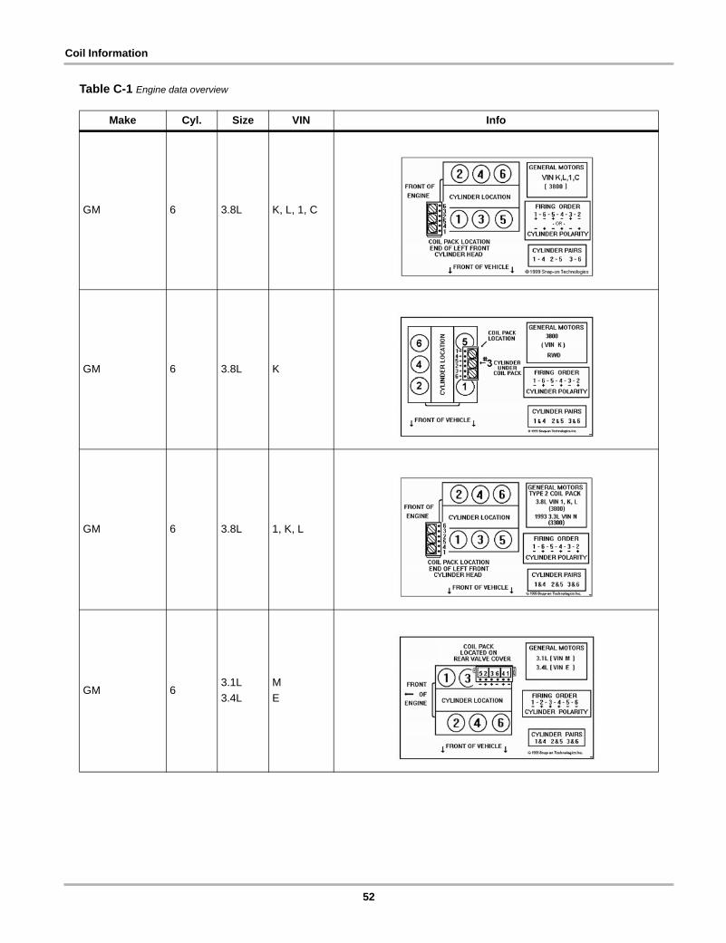
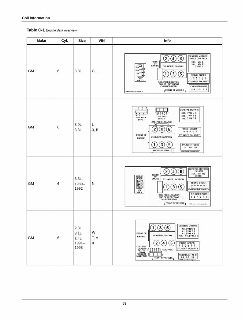
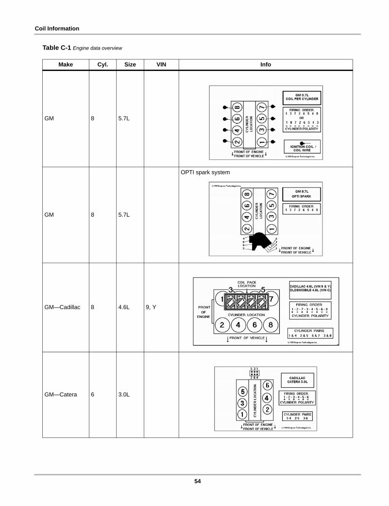
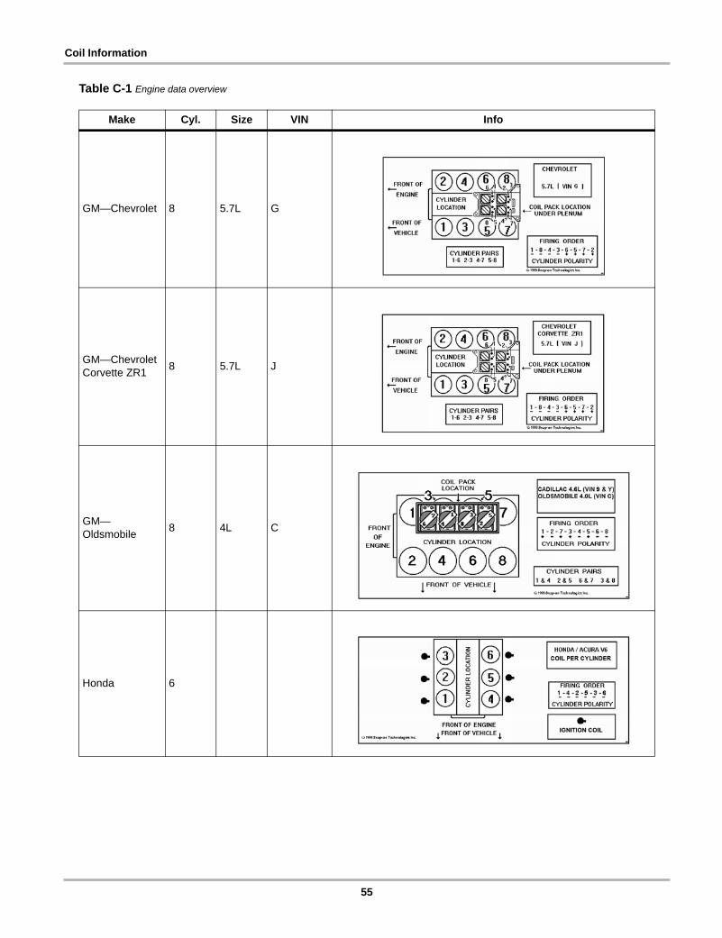
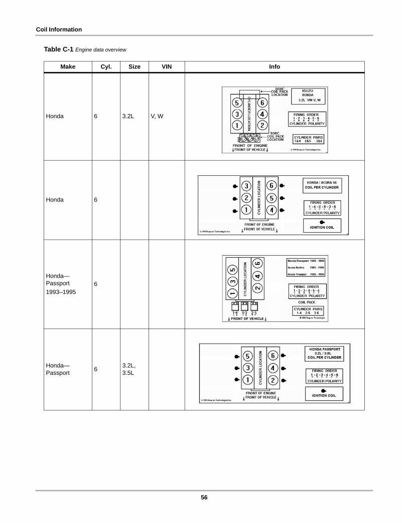
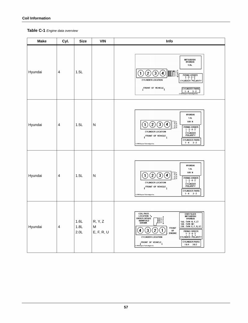
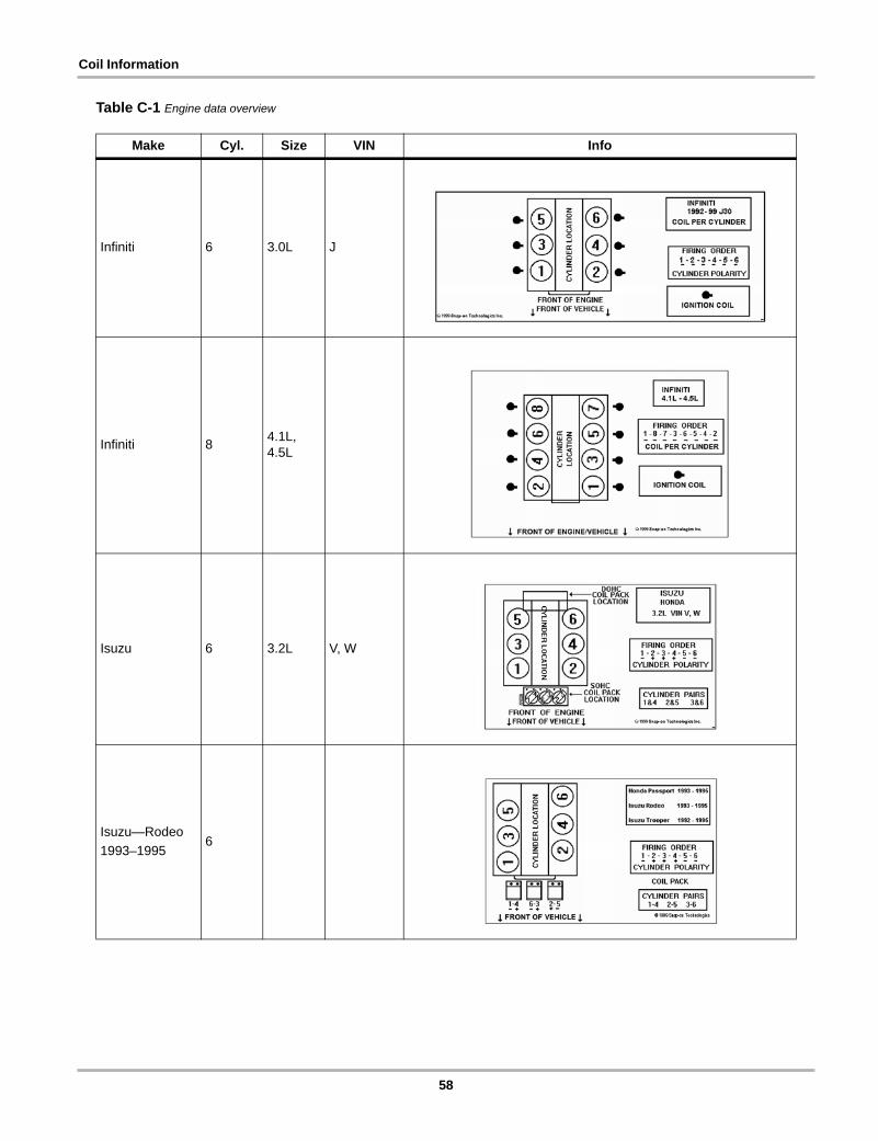
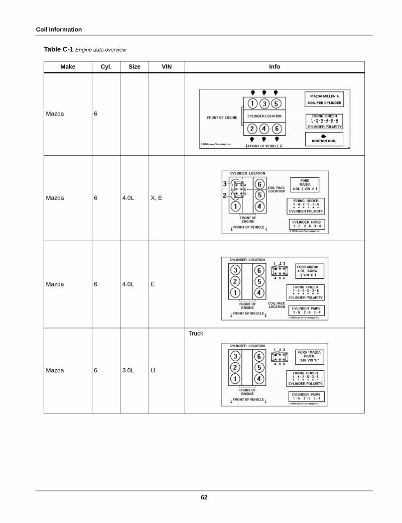
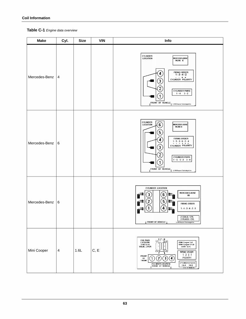
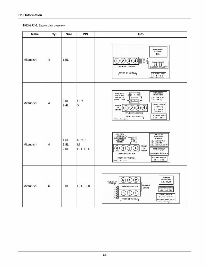
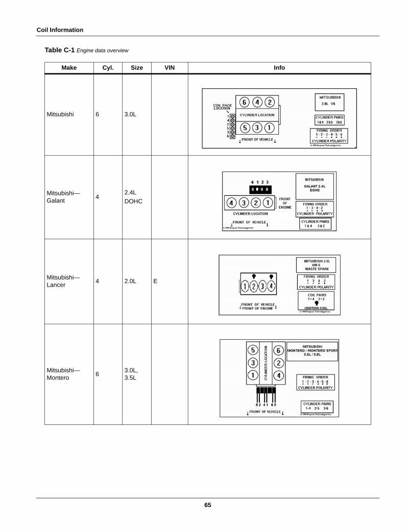
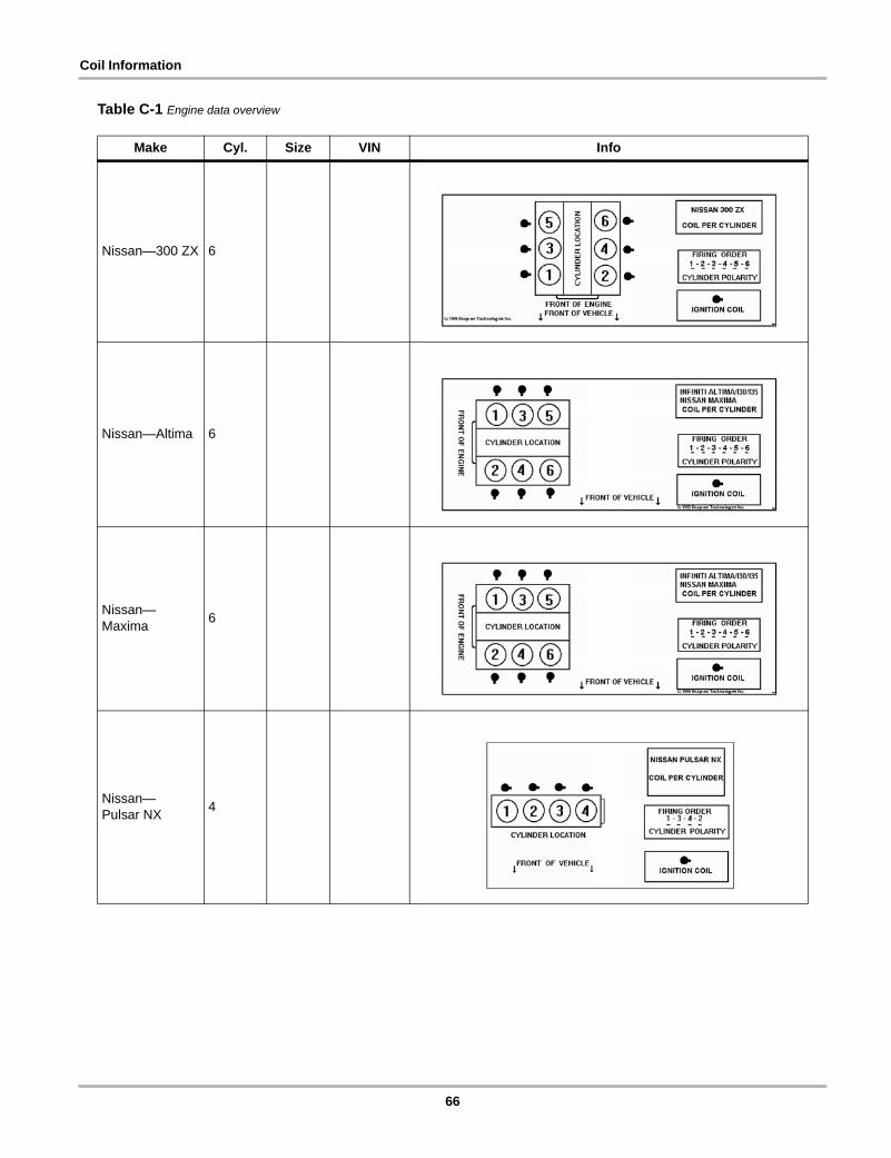
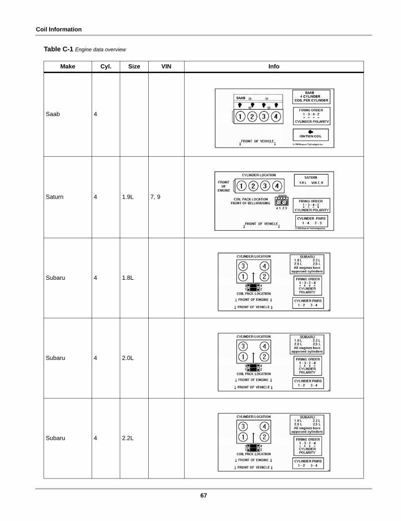
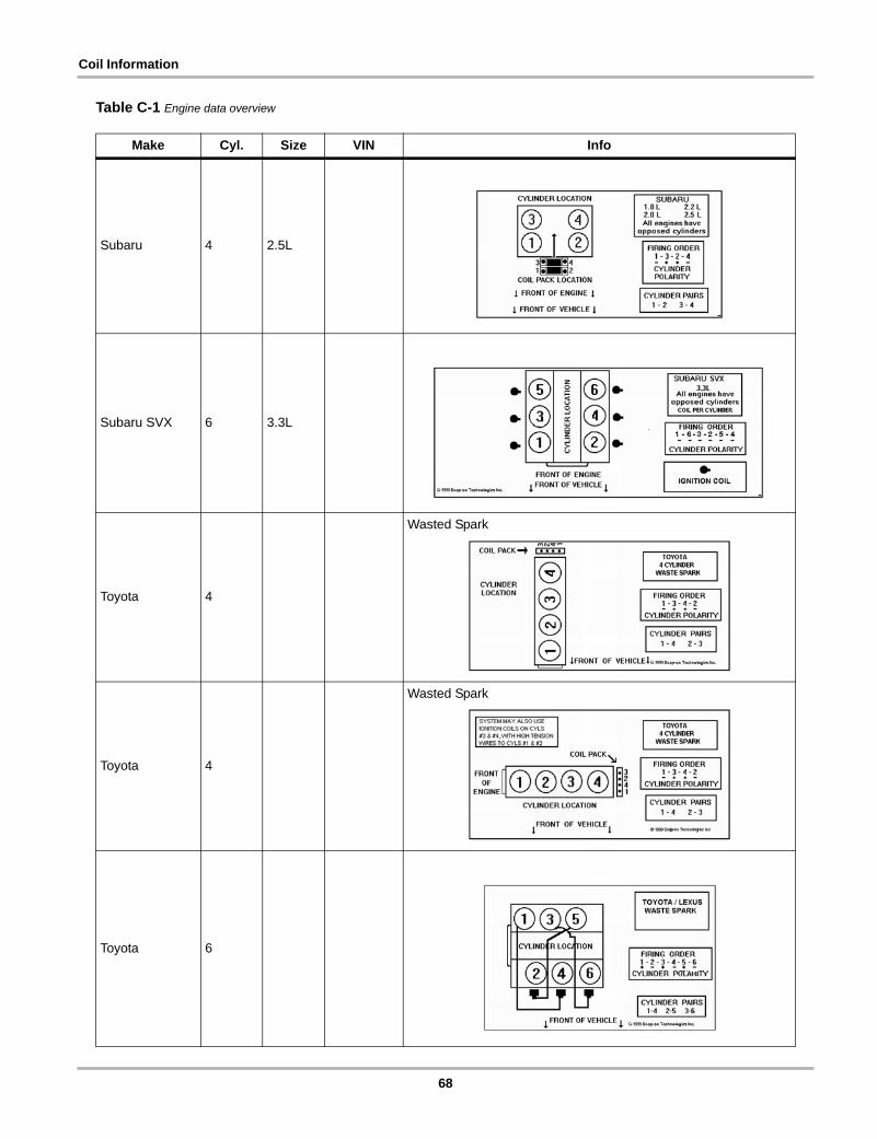
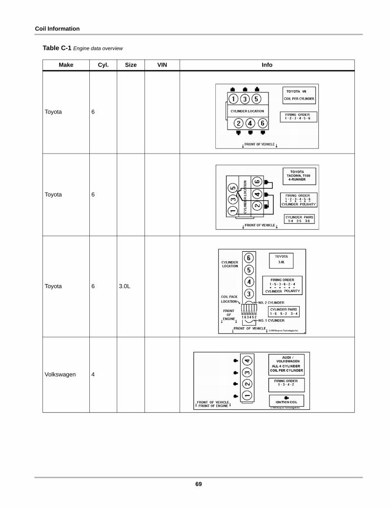
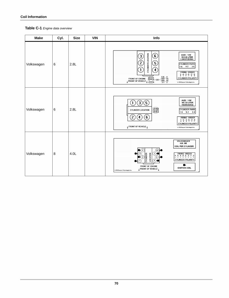
Table C-1 Engine data overview
Make Cyl. Size VIN Info
Acura 6
Audi 4 all
Audi 5 all
37
Coil Information
Audi 6 2.8L
Audi 6 2.8L
Audi 6 2.8L
Audi 8
Audi 8
Table C-1 Engine data overview
Make Cyl. Size VIN Info
38
Coil Information
BMW 4
BMW 6
BMW 8
Chrysler 4 1.6L R, Y, Z
Table C-1 Engine data overview
Make Cyl. Size VIN Info
39
Coil Information
Chrysler 4 1.8L M
Chrysler 4 2.0L C, Y
Chrysler 4 2.0L E, F, R, U
Chrysler 4 2.4L X
Chrysler 6 2.7L
Table C-1 Engine data overview
Make Cyl. Size VIN Info
40
Coil Information
Chrysler 6 3.0L B, C, J, K
Chrysler 6 3.0L B, C, J, K
Chrysler 6 3.2L
Chrysler 6 3.3L T
Chrysler 6 3.3L R, C, J
Table C-1 Engine data overview
Make Cyl. Size VIN Info
41
Coil Information
Chrysler 6 3.5L F
Chrysler 6 3.5L
Chrysler 6 3.8L L
Chrysler 10 8.0L
Dodge Monaco 6 U
Table C-1 Engine data overview
Make Cyl. Size VIN Info
42
Coil Information
Eagle Premier 6 U
Ford 4 1.5L J
Ford 4 2.0L 3, Z
Ford 4 2.0L P
Ford 4 2.5L C
Table C-1 Engine data overview
Make Cyl. Size VIN Info
43
Coil Information
Ford 6 2.5L L
Ford 6 3.0L S, U, Y
Ford 6 3.0L S
Ford 6 3.0L U
Ford 6 3.8L C, R
Table C-1 Engine data overview
Make Cyl. Size VIN Info
44
Coil Information
Ford 6 3.8L 4
Ford 6 4.0L X, E
Ford 6 4.2L 2
Ford 6 3.0L Y
Table C-1 Engine data overview
Make Cyl. Size VIN Info
45
Coil Information
Ford 6 3.2L P
Ford 6 4.0L E
Ford 8 4.6L V, X, 6
Table C-1 Engine data overview
Make Cyl. Size VIN Info
46
Coil Information
Ford 8 4.6L V, W, 9
Ford 8 4.6L V, 6, X
Ford 8 5.0L P
Table C-1 Engine data overview
Make Cyl. Size VIN Info
47
Coil Information
Ford 8 5.4L L, M, Z
Ford 8 3.4L N
Ford 10 6.8L
Ford 4 2.0L
Table C-1 Engine data overview
Make Cyl. Size VIN Info
48
Coil Information
Ford 6 3.0L U
Truck
Ford 6 3.8L 4
Windstar
GM 4 2.0L H
GM 4 2.2L 4
Table C-1 Engine data overview
Make Cyl. Size VIN Info
49
Coil Information
GM 4 2.5L R, U
GM 4 2.0L, 2.2L
14, G
GM 4 2.3L, 2.4L
A, D, 3T
GM 6 3.3L N
Table C-1 Engine data overview
Make Cyl. Size VIN Info
50
Coil Information
GM 63.3L1992
GM 6 3.4L S
GM 6 3.4L X, E
Table C-1 Engine data overview
Make Cyl. Size VIN Info
51
Coil Information
GM 6 3.8L K, L, 1, C
GM 6 3.8L K
GM 6 3.8L 1, K, L
GM 63.1L3.4L
ME
Table C-1 Engine data overview
Make Cyl. Size VIN Info
52
Coil Information
GM 6 3.8L C, L
GM 63.0L3.8L
L3, B
GM 63.3L1989–1992
N
GM 6
2.8L3.1L3.4L 1991–1993
WT, VX
Table C-1 Engine data overview
Make Cyl. Size VIN Info
53
Coil Information
GM 8 5.7L
GM 8 5.7L
OPTI spark system
GM—Cadillac 8 4.6L 9, Y
GM—Catera 6 3.0L
Table C-1 Engine data overview
Make Cyl. Size VIN Info
54
Coil Information
GM—Chevrolet 8 5.7L G
GM—Chevrolet Corvette ZR1 8 5.7L J
GM—Oldsmobile 8 4L C
Honda 6
Table C-1 Engine data overview
Make Cyl. Size VIN Info
55
Coil Information
Honda 6 3.2L V, W
Honda 6
Honda—Passport1993–1995
6
Honda—Passport 6 3.2L,
3.5L
Table C-1 Engine data overview
Make Cyl. Size VIN Info
56
Coil Information
Hyundai 4 1.5L
Hyundai 4 1.5L N
Hyundai 4 1.5L N
Hyundai 41.6L1.8L2.0L
R, Y, ZME, F, R, U
Table C-1 Engine data overview
Make Cyl. Size VIN Info
57
Coil Information
Infiniti 6 3.0L J
Infiniti 8 4.1L, 4.5L
Isuzu 6 3.2L V, W
Isuzu—Rodeo1993–1995
6
Table C-1 Engine data overview
Make Cyl. Size VIN Info
58
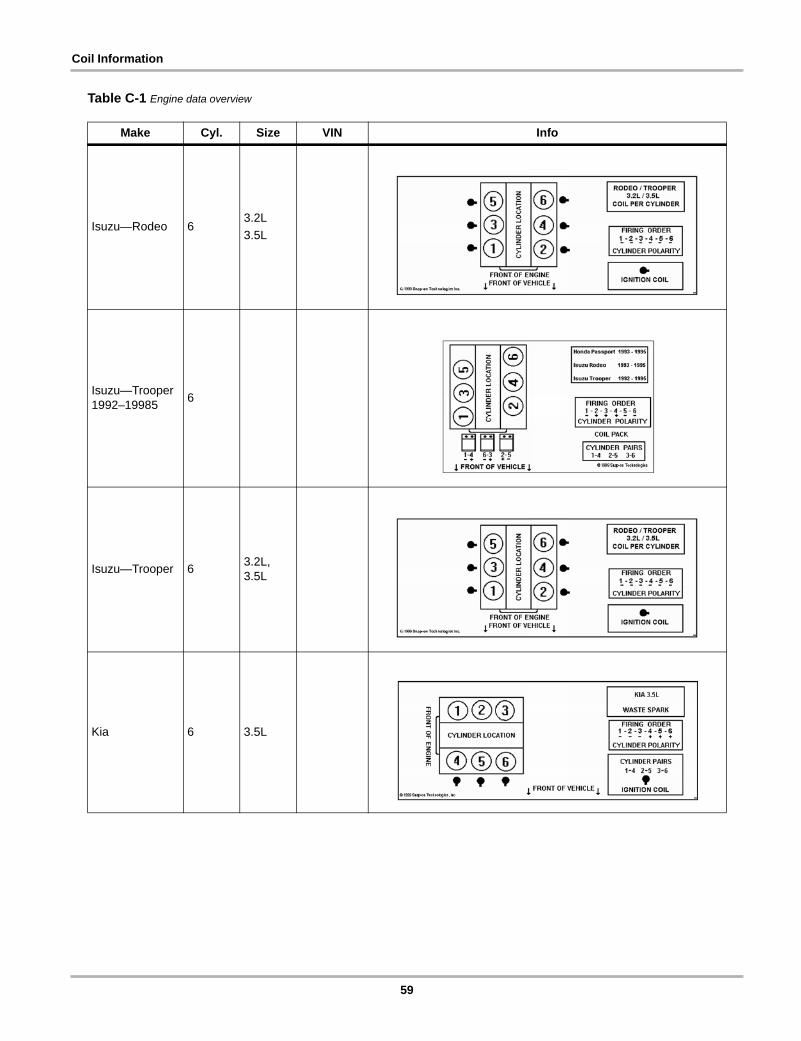
Coil Information
Isuzu—Rodeo 63.2L3.5L
Isuzu—Trooper 1992–19985 6
Isuzu—Trooper 6 3.2L, 3.5L
Kia 6 3.5L
Table C-1 Engine data overview
Make Cyl. Size VIN Info
59
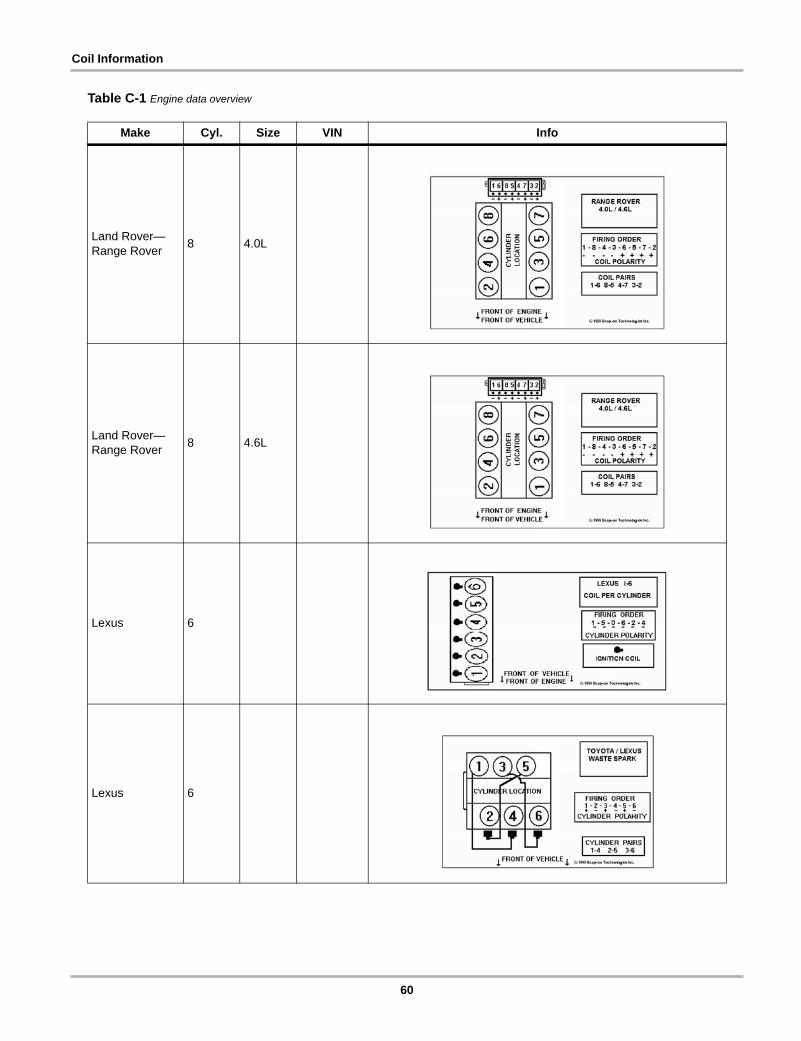
Coil Information
Land Rover— Range Rover 8 4.0L
Land Rover—Range Rover 8 4.6L
Lexus 6
Lexus 6
Table C-1 Engine data overview
Make Cyl. Size VIN Info
60
Coil Information
Mazda 4 1.6L
Mazda 4 1.8L
Mazda 4 1.9L
Mazda 4 2.5L C
Table C-1 Engine data overview
Make Cyl. Size VIN Info
61
Coil Information
Mazda 6
Mazda 6 4.0L X, E
Mazda 6 4.0L E
Mazda 6 3.0L U
Truck
Table C-1 Engine data overview
Make Cyl. Size VIN Info
62
Coil Information
Mercedes-Benz 4
Mercedes-Benz 6
Mercedes-Benz 6
Mini Cooper 4 1.6L C, E
Table C-1 Engine data overview
Make Cyl. Size VIN Info
63
Coil Information
Mitsubishi 4 1.5L
Mitsubishi 42.0L2.4L
C, YX
Mitsubishi 41.6L1.8L2.0L
R, Y, ZME, F, R, U
Mitsubishi 6 3.0L B, C, J, K
Table C-1 Engine data overview
Make Cyl. Size VIN Info
64
Coil Information
Mitsubishi 6 3.0L
Mitsubishi—Galant 4
2.4LDOHC
Mitsubishi—Lancer 4 2.0L E
Mitsubishi—Montero 6 3.0L,
3.5L
Table C-1 Engine data overview
Make Cyl. Size VIN Info
65
Coil Information
Nissan—300 ZX 6
Nissan—Altima 6
Nissan—Maxima 6
Nissan—Pulsar NX 4
Table C-1 Engine data overview
Make Cyl. Size VIN Info
66
Coil Information
Saab 4
Saturn 4 1.9L 7, 9
Subaru 4 1.8L
Subaru 4 2.0L
Subaru 4 2.2L
Table C-1 Engine data overview
Make Cyl. Size VIN Info
67
Coil Information
Subaru 4 2.5L
Subaru SVX 6 3.3L
Toyota 4
Wasted Spark
Toyota 4
Wasted Spark
Toyota 6
Table C-1 Engine data overview
Make Cyl. Size VIN Info
68
Coil Information
Toyota 6
Toyota 6
Toyota 6 3.0L
Volkswagen 4
Table C-1 Engine data overview
Make Cyl. Size VIN Info
69
Coil Information
Volkswagen 6 2.8L
Volkswagen 6 2.8L
Volkswagen 8 4.0L
Table C-1 Engine data overview
Make Cyl. Size VIN Info
70

Distributorless Ignition System AdapterUser Manual
©2009 Snap-on Incorporated. All rights reserved. ZEETA309A15 Rev. D