Embed Size (px)
Citation preview
Page 1
DIRSIG Short Course
DIRSIG
A complex graphics application for modeling a variety of remote image acquisition systems
DIRSIG Short Course
What does a vehicle look like?
• The truck leaves a shadow on the ground– The ground is cooler because it has been in the shade.
• You can see a reflection of the hot engine in the asphalt as it drives by.
DIRSIG Short Course
DIRSIG:Applicable Areas
• Sensor Prototyping– Construct and test a new sensor in a virtual environment– Evaluate design trades– Produce example products for customers
• Algorithm Testing– Decrease amount expensive field collections– Control all the image formation variables– Per-pixel truth allows for better evaluation
• Algorithm Training– Predict observations that may be found in images to pre-train complex algorithms.
• Analyst Training– Create custom training examples– Test the sensitivity of the analyst to phenomenology– Provide a tool to hypothesis about the nature of phenomenology
DIRSIG Short Course
ThermalModel
SensorModel
DIRSIG
WeatherDatabase
AtmosphericDatabase
Image FusionImage FusionDemonstrationsDemonstrations
Thermal IR and LowThermal IR and Low--Light ImageryLight Imagery
Hyperspectral Hyperspectral ImageryImageryand Target Mapsand Target Maps
SubSub--Pixel Detection PerformancePixel Detection Performance(ROC curves)(ROC curves)
Max Intensity First/Second Peak
Obscured TargetObscured TargetDetectionDetection
Range GatedRange GatedLADARLADAR
Simulated DataSimulated DataProductsProducts
SimulatedSimulatedData ExploitationData Exploitation
ProductsProducts
RadiometryModel
ObjectGeometry
ThermodynamicOptical Properties
Polarized/Unpolarized Polarized/Unpolarized Broadband, multiBroadband, multi--, hyper, hyper-- or ultraor ultra--spectral imageryspectral imagery
Target and background Target and background databases with spatial and databases with spatial and spectral variability (clutter)spectral variability (clutter)
FullyFully--spectral radiation spectral radiation propagationpropagation
DIRSIG Short Course
CAD Models from Rhino3DCAD Models from Rhino3D
Tree Models from Tree ProTree Models from Tree Pro
DIRSIG Scene Building ToolsDIRSIG Scene Building Tools
Facetized Facetized Terrain fromTerrain fromDEM/DTEDDEM/DTED
Terrain Attribute MapsTerrain Attribute Maps
Target models fromTarget models fromPRISM/MuSESPRISM/MuSES
Generic modelsGeneric modelsvia DXF/OBJ importvia DXF/OBJ import BRDFs, EmissivitiesBRDFs, Emissivities
Scattering Phase Scattering Phase FunctionsFunctions
Nearly specular
Sensor DescriptionSensor Description
Visible RegionVisible RegionDaytimeDaytime
Visible RegionVisible RegionNighttimeNighttime
Thermal RegionThermal RegionNighttimeNighttime
DIRSIG Short Course
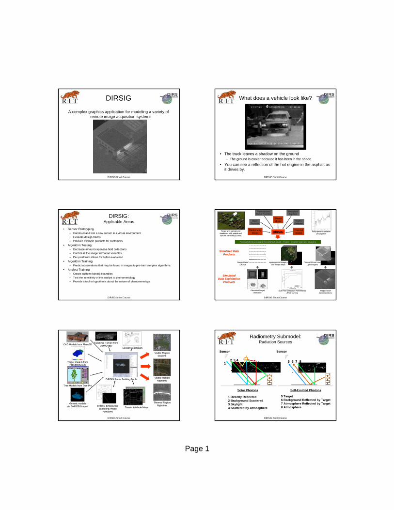
Radiometry Submodel:Radiation Sources
1 Directly Reflected 2 Background Scattered3 Skylight4 Scattered by Atmosphere
Solar Photons Self-Emitted Photons
5 Target6 Background Reflected by Target7 Atmosphere Reflected by Target8 Atmosphere
SensorSensor SensorSensor
12 3 4 5 6 7 8
Page 2
DIRSIG Short Course
MeteorologicalConditions
Sky ExposureDirectInsolation
DiffuseInsolation
MaterialProperties
Scene Geometry
DiffuseInsolation
THERM Environmental Inputs
DIRSIG Short Course
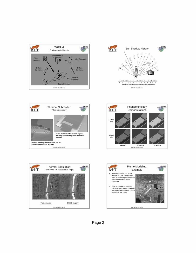
Sun Shadow History
131
2
3
4
567
8
9
10
11
12
0
0.0 1.0 1.0 0.4 0. 3 1.0 0.0 0.0 0.0 0.0 1.0 1.0 1.0 1.0
0 1 2 3 4 5 6 7 8 9 10 11 12 13
( total shadow ) 0.0 < direct insolation modifier < 1.0 ( total sunlight )
DIRSIG Short Course
Radiant Radiant ““shadingshading”” beneath truck and an beneath truck and an internal power source (engine)internal power source (engine)
““SoftSoft”” shadows in the thermal regionsshadows in the thermal regionsresulting from utilizing solar shadowingresulting from utilizing solar shadowinghistorieshistories
Thermal Submodel:Phenomenology
DIRSIG Short Course
9:45 EDT9:45 EDT 10:15 EDT10:15 EDT 10:45 EDT10:45 EDT
Phenomenology Demonstrations
3 mph3 mphwindwind
10 mph10 mphwindwind
DIRSIG Short Course
DIRSIG ImageryDIRSIG ImageryTruth ImageryTruth Imagery
Thermal Simulation:Rochester NY in Winter at Night
DIRSIG Short Course
Plume Modeling:Example
• A simulation of a gas plume release at a the Nevada Test Site. The actual plume release was used to validate our simulation.
• If the simulation is accurate, then costly and environmentally unfriendly field releases can be avoided in the future.
Page 3
DIRSIG Short Course
0
0.05
0.1
0.15
0.2
2 3 4 5 6 7 8 9 10 11
wavelength (μm)
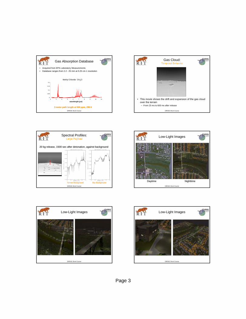
Methyl Chloride CH3Cl
3 meter path length at 500 ppm, 298 K3 meter path length at 500 ppm, 298 K
Gas Absorption Database
• Acquired from EPA Laboratory Measurements• Database ranges from 2.2 - 25 mm at 0.25 cm-1 resolution
DIRSIG Short Course
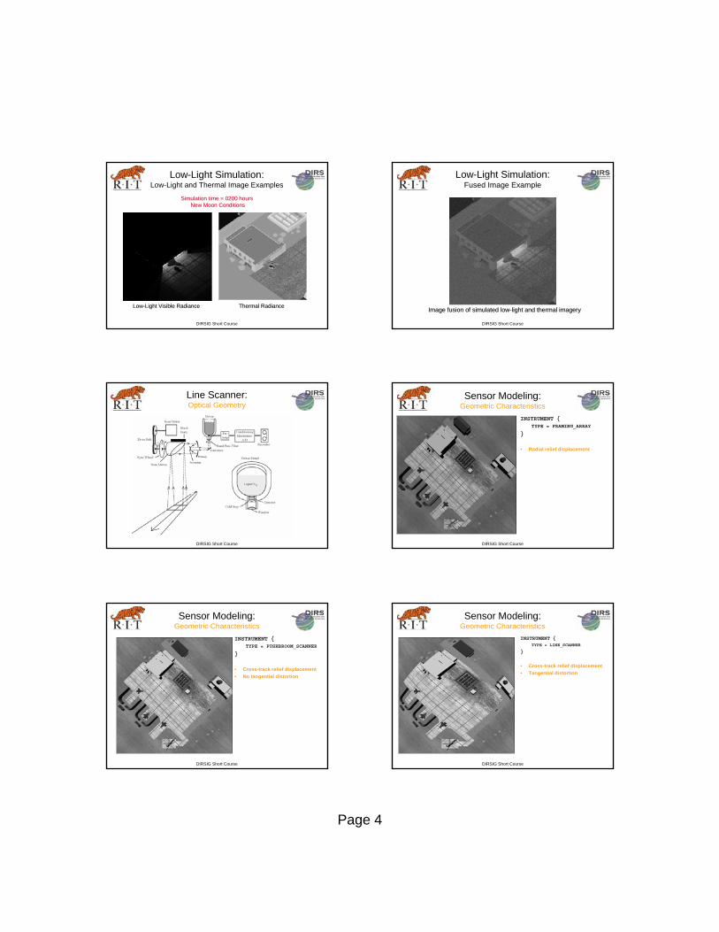
Gas Cloud:Temporal Behavior
• This movie shows the drift and expansion of the gas cloud over the terrain– From 25 ms to 600 ms after release
DIRSIG Short Course
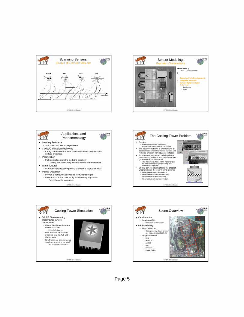
Spectral Profiles:Large Payload
20 kg release, 1500 sec after detonation, against background20 kg release, 1500 sec after detonation, against background
Terrain BackgroundTerrain Background Sky BackgroundSky Background
DIRSIG Short Course
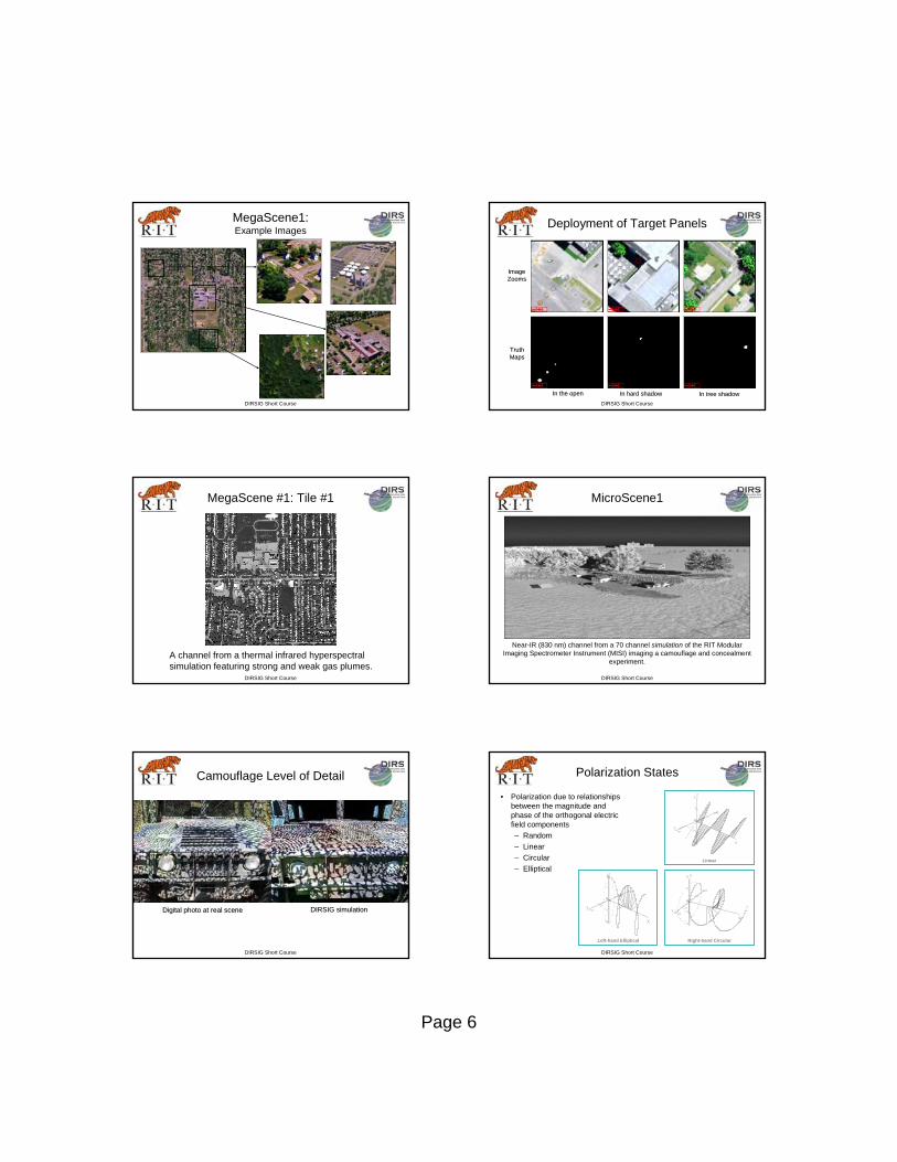
Low-Light Images
DaytimeDaytime NighttimeNighttime
DIRSIG Short Course
Low-Light Images
DIRSIG Short Course
Low-Light Images
Page 4
DIRSIG Short Course
Low-Light Simulation:Low-Light and Thermal Image Examples
LowLow--Light Visible RadianceLight Visible Radiance Thermal RadianceThermal Radiance
Simulation time = 0200 hours Simulation time = 0200 hours New Moon ConditionsNew Moon Conditions
DIRSIG Short Course
Low-Light Simulation:Fused Image Example
Image fusion of simulated lowImage fusion of simulated low--light and thermal imagerylight and thermal imagery
DIRSIG Short Course
Line Scanner:Optical Geometry
DIRSIG Short Course
Sensor Modeling:Geometric Characteristics
INSTRUMENT {TYPE = FRAMING_ARRAY
}
• Radial relief displacement
DIRSIG Short Course
Sensor Modeling:Geometric Characteristics
INSTRUMENT {TYPE = PUSHBROOM_SCANNER
}
• Cross-track relief displacement• No tangential distortion
DIRSIG Short Course
Sensor Modeling:Geometric Characteristics
INSTRUMENT {TYPE = LINE_SCANNER
}
• Cross-track relief displacement• Tangential distortion
Page 5
DIRSIG Short Course
Scanning Sensors:Sources of Geometric Distortion
DIRSIG Short Course
Sensor Modeling:Geometric Characteristics
INSTRUMENT {TYPE = LINE_SCANNER
}
• Cross-track relief displacement• Tangential distortion• General flight orientation
distortions– Gentle role– Jitter
DIRSIG Short Course
Applications and Phenomenology
• Loading Problems– Sky, cloud and tree shine problems
• Cavity/Calibration Problems– Cavity radiance effects from chambers/cavities with non-ideal
surface properties.• Polarization
– Full-spectral polarimetric modeling capability• Currently heavily limited by available material characterizations
• Water/Littoral– In-water scattering/absorption to understand adjacent effects.
• Plume Detection– Provide a framework to evaluate instrument designs.– Provide a source of data for rigorously testing algorithms.
• Truth is known for every pixel.
DIRSIG Short Course
The Cooling Tower Problem
• Problem:– Estimate the cooling load (water
temperature) from observed radiances.• The observed radiance is a combination of
direct emission from the viewed surface and reflected emission from adjacent surfaces.
• To evaluate the expected variations in the tower leaving radiance, a model of the tower geometry can be constructed.
– The individual surfaces within the tower can be attributed with unique emissivity and reflectance properties.
• DIRSIG can provide insight into the effect of uncertainties on the tower leaving radiance.
– Uncertainty in water temperature.– Uncertainty in surface temperatures.– Uncertainty in surface emissivity.– Uncertainty in internal construction.
DIRSIG Short Course
Cooling Tower Simulation
• DIRSIG Simulation using precomputed surface temperatures.– Cannot directly see the warm
water in the tower• All multiple bounce!
– Note apparent temperature gradients near fan hub and shroud walls.
– Small holes are from sampling small grooves in the top “deck”
• Will be smoothed with PSF
DIRSIG Short Course
Scene Overview
• Candidate site– Irondequoit NY
• North-east corner of city
• Data Availability– Field Collections
• Close proximity allows for easy and frequent ground collects.
– Image Collections• MISI• IKONOS• AVIRIS• MTI• Hyperion• Kodak CitiPix
Tile #1Tile #1
Page 6
DIRSIG Short Course
MegaScene1:Example Images
DIRSIG Short Course
Deployment of Target Panels
In the openIn the open In hard shadowIn hard shadow In tree shadowIn tree shadow
ImageImageZoomsZooms
TruthTruthMapsMaps
DIRSIG Short Course
MegaScene #1: Tile #1
A channel from a thermal infrared hyperspectral simulation featuring strong and weak gas plumes.
DIRSIG Short Course
MicroScene1
Near-IR (830 nm) channel from a 70 channel simulation of the RIT Modular Imaging Spectrometer Instrument (MISI) imaging a camouflage and concealment
experiment.
DIRSIG Short Course
Camouflage Level of Detail
Digital photo at real sceneDigital photo at real scene DIRSIG simulationDIRSIG simulation
DIRSIG Short Course
Polarization States
• Polarization due to relationships between the magnitude and phase of the orthogonal electric field components– Random– Linear– Circular– Elliptical
Linear
Left-hand Elliptical Right-hand Circular
Page 7
DIRSIG Short Course
“Real Material” Reflectance
• Real materials are complex, with two basic reflectance components– Surface– Volume
• Surface reflectance highly color neutral
• Volume reflectance →color
• Umov’s effect: DOP and brightness inversely proportional
DIRSIG Short Course
Demonstration of Polarization
Vertically Polarized Filter Horizontally Polarized Filter
DIRSIG Short Course
S0
S2
S1
DOP
Imaging System Demonstration: “Magic 8-ball”
DIRSIG Short Course
AFRL Polarimetric Images
S0S0 S1S1
DOLPDOLP S2S2
DIRSIG Short Course
Army TARDEC Collections
Degree of Polarization
Color Visualization of Stokes Paramaters
COTS Polarized COTS Polarized Imaging SystemImaging System
This work conducted by Grant This work conducted by Grant GerhartGerhartat Army TARDECat Army TARDEC
DIRSIG Short Course
First DIRSIG Polarimetric Images
S0S0 S1S1
S2S2 DOLPDOLPUsing NewUsing New
Sensor/PlatformSensor/PlatformModelModel
Page 8
DIRSIG Short Course
LM, RIT and AFRL Partnership
Degree of PolarizationRGB Color
S0 @ 550 nm
S1 @ 550 nm
S2 @ 550 nm
• A simple, polarized scene simulation– Vehicle BRDF modeled using AFRL’s
multi-parameter, polarized BRDF model.– Grass modeled using RIT’s Shell
Background model.– No sensor noise or MTF effects.
DIRSIG Short CourseBack Scatter (RGB) Side Looking (RGB) Forward Scatter (RGB)
DIRSIG BRDF Model
• Sample Imagery (Color Renderings)– Color Images: Red (S0: 650nm), Green (S0: 550nm); Blue (S0:
450nm)– 3 Viewing Angles (Forward, Side and Backscatter)
DIRSIG Short CourseBack Scatter (DOLP) Side Looking (DOLP) Forward Scatter (DOLP)
DIRSIG BRDF Model
• Sample Imagery– DOLP Images (650nm)– 3 Viewing Angles (Forward, Side and Backscatter)
DIRSIG Short Course
Temporal Pulse
0
0.2
0.4
0.6
0.8
1
1.2
4 3.5 3 2.5 2 1.5 1 0.5 0
Seconds
Pow
er
x
y
Power
LADAR/LIDAR
• The scene is stimulated with a pulsed beam that has a spatial, spectral and temporal shape.– The goal is to produce a simulation environment that can simulate as much
physics as possible and provide a tool for design trade studies and algorithm testing.
DIRSIG Short Course
LIDAR at MicroScene1
Time/DistanceGrass on hillGrass on hill
Shed Shed RoofRoof
HumveeHumvee ““LateLate”” photons tphotons that got hat got ““lostlost”” in in grassgrass
PortablePortableGeneratorGenerator
Lighter coloredLighter coloreddirtdirt
ShedShed““ShadowShadow””
DIRSIG Short Course
Topographical LIDAR Demo
Der
ived
Topo
-Pro
duct
Overhead Slant View
DIR
SIG
Pas
sive
Imag
ery
Slant ViewOverhead
Topographic Products Courtesy of
Page 9
DIRSIG Short Course
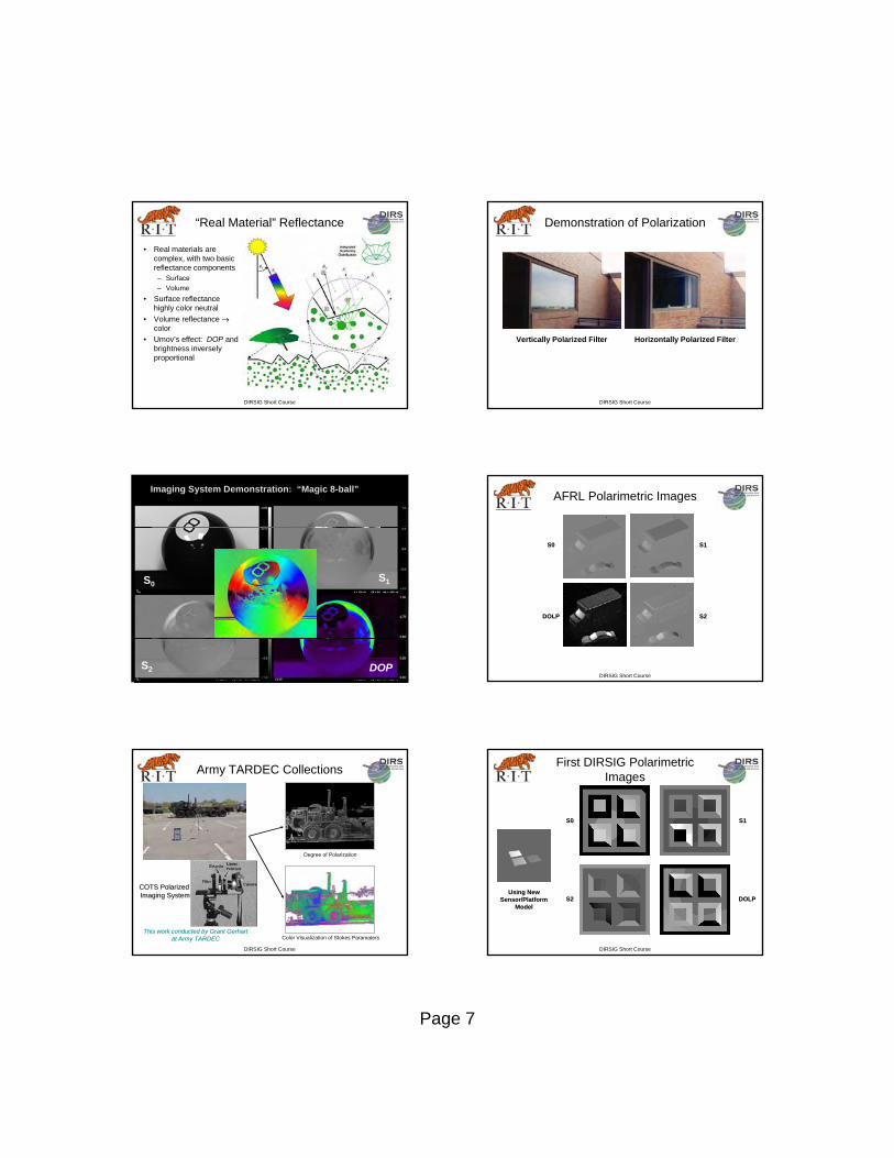
Camouflaged Vehicle Simulation
Time
DIRSIGCAD Models
Height TruthImagery
LIDARPulse Cubes
Top of net Spreader Humvee roof
t003 t012 t022 t033
Humvee shadow
t115
Humvee hood
t049
DIRSIG Short Course
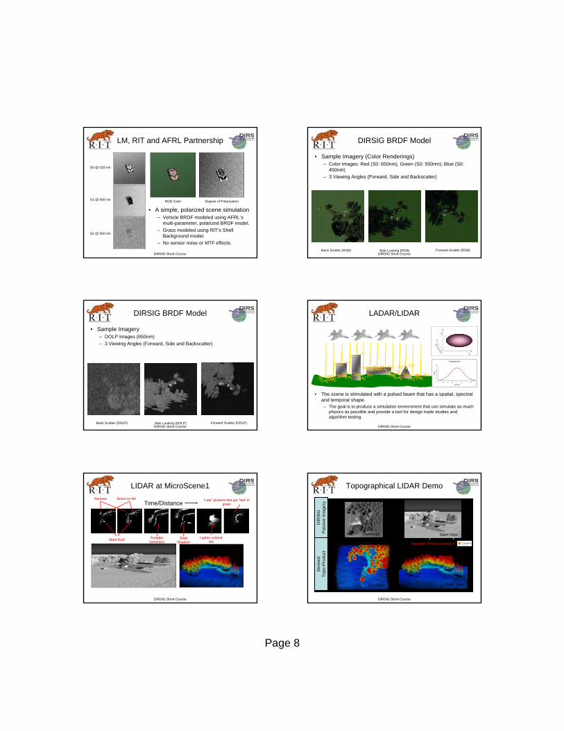
T-72 Tank
HMVVV
RIT Topographic Processing
DIRSIG Short Course
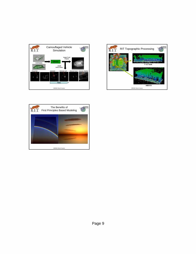
The Benefits ofFirst Principles Based Modeling