Embed Size (px)
Citation preview

REPUBLIC OF INDONESIA MINISTRY OF TRANSPORTATION
CIVIL AVIATION SAFETY REGULATION (CASR)
PART 25 AIRWORTHINESS STANDARDS:
TRANSPORT CATEGORY AIRPLANES
CASR 25/ R 5/June 2003 Page 1
LAMPIRAN KEPUTUSAN MENTERI PERHUBUNGAN NOMOR : KM. 26 Year 2003 TANGGAL : 10 June 2003
CIVIL AVIATION SAFETY REGULATIONS (C.A.S.R.)
PART 25 Revision 05
AIRWORTHINESS STANDARDS: TRANSPORT CATEGORY AIRPLANES
REPUBLIC OF INDONESIA MINISTRY OF TRANSPORTATION
CASR 25/ R 5/June 2003 Page 2
PART 25 AIRWORTHINESS STANDARDS:
TRANSPORT CATEGORY AIRPLANES
TABLE OF CONTENTS
TABLE OF CONTENTS................................................................................................... i
SUBPART A - GENERAL..............................................................................................1
25.0 Purpose..................................................................................................1
25.1 Applicability ............................................................................................1
25.2 Special Retroactive Requirements .........................................................1
SUBPART B - FLIGHT ..................................................................................................2
GENERAL..............................................................................................2
25.21 Proof of Compliance...............................................................................2
25.23 Load Distribution Limits ..........................................................................2
25.25 Weight Limits..........................................................................................3
25.27 Center of Gravity Limits..........................................................................3
25.29 Empty Weight and Corresponding Center of Gravity..............................3
25.31 Removable Ballast .................................................................................4
25.33 Propeller Speed and Pitch Limits ...........................................................4
PERFORMANCE ...................................................................................4
25.101 General ..................................................................................................4
25.103 Stalling Speed ........................................................................................6
25.105 Takeoff ...................................................................................................6
25.107 Takeoff speeds.......................................................................................7
25.109 Accelerate-Stop Distance.......................................................................8
25.111 Takeoff path. ..........................................................................................9
25.113 Takeoff Distance and Takeoff Run.......................................................10
25.115 Takeoff Flight Path ...............................................................................10
25.117 Climb: General .....................................................................................11
25.119 Landing Climb: All Engine Operating....................................................11
25.121 Climb: One Engine in Operative...........................................................11
25.123 Enroute Flight Paths.............................................................................12
25.125 Landing ................................................................................................13
CONTROLLABILITY AND MANEUVERABILITY ...............................14
25.143 General ................................................................................................14
Table of Contents Page i
25.145 Longitudinal Control .............................................................................15
25.147 Directional and Lateral Control.............................................................16
25.149 Minimum Control Speed.......................................................................17
TRIM ....................................................................................................19
25.161 Trim......................................................................................................19
STABILITY...........................................................................................20
25.171 General ................................................................................................20
25.173 Static Longitudinal Stability ..................................................................20
25.175 Demonstration of Static Longitudinal Stability ......................................21
25.177 Static Directional and Lateral Stability ..................................................22
25.181 Dynamic Stability..................................................................................23
STALLS ...............................................................................................23
25.201 Stall Demonstration..............................................................................23
25.203 Stall Characteristics..............................................................................24
25.207 Stall Warning........................................................................................24
GROUND AND WATER HANDLING CHARACTERISTICS ...............25
25.231 Longitudinal Stability and Control .........................................................25
25.233 Directional Stability and Control ...........................................................25
25.235 Taxiing Condition .................................................................................25
25.237 Wind Velocities.....................................................................................26
25.239 Spray Characteristics, Control, and Stability on Water.........................26
MISCELLANEOUS FLIGHT REQUIREMENTS ..................................27
25.251 Vibration and Buffeting .........................................................................27
25.253 High Speed Characteristics..................................................................27
25.255 Out-of-trim Characteristics ...................................................................28
SUBPART C - STRUCTURE .......................................................................................30
GENERAL............................................................................................30
25.301 Loads ...................................................................................................30
25.303 Factor of Safety....................................................................................30
25.305 Strength and Deformation ....................................................................30
25.307 Proof of Structure .................................................................................31
FLIGHT LOADS...................................................................................31
25.321 General ................................................................................................31
FLIGHT MANEUVER AND GUST CONDITIONS................................32
Table of Contents Page ii
25.331 Symmetric Maneuvering Conditions.....................................................32
25.333 Flight Maneuvering Envelope...............................................................33
25.335 Design Airspeeds .................................................................................34
25.337 Limit Maneuvering Load Factors ..........................................................35
25.341 Gust and Turbulence Loads .................................................................36
25.343 Design Fuel and Oil Loads ...................................................................37
25.345 High Lift Devices ..................................................................................38
25.349 Rolling Conditions ................................................................................38
25.351 Yaw Maneuver Conditions ...................................................................39
SUPPLEMENTARY CONDITIONS......................................................40
25.361 Engine Torque......................................................................................40
25.363 Side Load on Engine and Auxiliary Power Unit Mounts .......................40
25.365 Pressurized Cabin Loads .....................................................................41
25.367 Unsymmetrical Loads Due to Engine Failure .......................................42
25.371 Gyroscopic Loads.................................................................................42
25.373 Speed Control Devices.........................................................................42
CONTROL SURFACE AND SYSTEM LOADS ...................................43
25.391 Control Surface Loads: General ...........................................................43
25.393 Loads Parallel to Hinge Line ................................................................43
25.395 Control System.....................................................................................43
25.397 Control System Loads..........................................................................44
25.399 Dual Control System ............................................................................44
25.405 Secondary Control System...................................................................45
25.407 Trim Tab Effects...................................................................................45
25.409 Tabs .....................................................................................................45
25.415 Ground Gust Conditions.......................................................................46
25.427 Unsymmetrical Loads...........................................................................46
25.445 Auxiliary Aerodynamic Surfaces...........................................................47
25.457 Wing Flaps ...........................................................................................47
25.459 Special Devices....................................................................................47
GROUND LOADS................................................................................48
25.471 General ................................................................................................48
25.473 Landing Load Conditions and Assumptions .........................................48
25.477 Landing Gear Arrangement..................................................................49
25.479 Level Landing Conditions .....................................................................49
25.481 Tail Down Landing Conditions..............................................................50
Table of Contents Page iii
25.483 One-gear Landing Conditions ..............................................................50
25.485 Side Load Conditions ...........................................................................51
25.487 Rebound Landing Condition.................................................................51
25.489 Ground Handling Conditions ................................................................51
25.491 Taxi, Takeoff and Landing Roll.............................................................51
25.493 Braked Roll Conditions.........................................................................52
25.495 Turning .................................................................................................52
25.497 Tail Wheel Yawing................................................................................52
25.499 Nose-wheel Yaw and Steering .............................................................52
25.503 Pivoting ................................................................................................53
25.507 Reversed Braking.................................................................................53
25.509 Towing Loads.......................................................................................54
25.511 Ground Load: Unsymmetrical Loads on Multiple Wheel Units .............55
25.519 Jacking and Tie-down Provisions.........................................................56
WATER LOADS ..................................................................................57
25.521 General ................................................................................................57
25.523 Design Weights and Center of Gravity Positions..................................57
25.525 Application of Loads.............................................................................57
25.527 Hull and Main Float Load Factors ........................................................57
25.529 Hull and Main Float Landing Conditions...............................................58
25.531 Hull and Main Float Takeoff Condition .................................................59
25.533 Hull and Main Float Bottom Pressures .................................................59
25.535 Auxiliary Float Loads............................................................................61
25.537 Seawing Loads.....................................................................................62
EMERGENCY LANDING CONDITIONS .............................................62
25.561 General ................................................................................................62
25.562 Emergency Landing Dynamic Conditions.............................................63
25.563 Structural Ditching Provisions ..............................................................64
FATIGUE EVALUATION .....................................................................64
25.571 Damage Tolerance and Fatigue Evaluation of Structure......................64
LIGHTNING PROTECTION .................................................................66
25.581 Lightning Protection..............................................................................66
SUBPART D - DESIGN AND CONSTRUCTION.........................................................68
GENERAL............................................................................................68
Table of Contents Page iv
25.601 General ................................................................................................68
25.603 Materials...............................................................................................68
25.605 Fabrication Methods.............................................................................68
25.607 Fasteners .............................................................................................68
25.609 Protection of Structure..........................................................................69
25.611 Accessibility Provisions ........................................................................69
25.613 Material Strength Properties and Design Values..................................69
25.619 Special Factors ....................................................................................70
25.621 Casting Factors ....................................................................................70
25.623 Bearing Factors....................................................................................71
25.625 Fitting Factors ......................................................................................71
25.629 Aeroelastic Stability Requirements.......................................................72
25.631 Bird Strike Damage ..............................................................................73
CONTROL SURFACES.......................................................................74
25.651 Proof of Strength ..................................................................................74
25.655 Installation ............................................................................................74
25.657 Hinges ..................................................................................................74
CONTROL SYSTEMS .........................................................................74
25.671 General ................................................................................................74
25.672 Stability Augmentation and Automatic and Power Operated Systems ...............................................................................................75
25.675 Stops ....................................................................................................76
25.677 Trim Systems .......................................................................................76
25.679 Control System Gust Locks..................................................................76
25.681 Limit Load Static Tests .........................................................................76
25.683 Operation Tests....................................................................................77
25.685 Control System Details.........................................................................77
25.689 Cable Systems .....................................................................................77
25.693 Joints....................................................................................................78
25.697 Lift and Drag Devices, Controls............................................................78
25.699 Lift and Drag Device Indicator ..............................................................78
25.701 Flap Interconnection.............................................................................79
25.703 Takeoff Warning System......................................................................79
LANDING GEAR .................................................................................80
25.721 General ................................................................................................80
25.723 Shock Absorption Tests .......................................................................80
Table of Contents Page v
25.725 Limit Drop Tests ...................................................................................80
25.727 Reserve Energy Absorption Drop Tests ...............................................81
25.729 Retracting Mechanism..........................................................................82
25.731 Wheels .................................................................................................83
25.733 Tires. ....................................................................................................83
25.735 Brakes ..................................................................................................84
25.737 Skis ......................................................................................................85
FLOATS AND HULLS .........................................................................86
25.751 Main Float Buoyancy............................................................................86
25.753 Main Float Design ................................................................................86
25.755 Hulls .....................................................................................................86
PERSONNEL AND CARGO ACCOMMODATIONS............................86
25.771 Pilot Compartment................................................................................86
25.772 Pilot Compartment Doors .....................................................................87
25.773 Pilot Compartment View.......................................................................87
25.775 Windshields and Windows ...................................................................88
25.777 Cockpit Controls ...................................................................................88
25.779 Motion and Effect of Cockpit Controls ..................................................89
25.781 Cockpit Control Knob Shape ................................................................90
25.783 Doors....................................................................................................91
25.785 Seats, Berths, Safety Belts, and Harnesses.........................................92
25.787 Stowage Compartments.......................................................................94
25.789 Retention of Items of Mass in Passenger and Crew Compartments and Galleys ..........................................................................................94
25.791 Passenger Information Signs and Placards .........................................94
25.793 Floor Surfaces......................................................................................95
EMERGENCY PROVISIONS...............................................................95
25.801 Ditching ................................................................................................95
25.803 Emergency Evacuation ........................................................................95
25.807 Passenger Emergency Exits ................................................................96
25.809 Emergency Exit Arrangement ..............................................................99
25.810 Emergency Egress Assist Means and Escape Routes....................... 100
25.811 Emergency Exit Marking .................................................................... 102
25.812 Emergency Lighting............................................................................ 103
25.813 Emergency Exit Access...................................................................... 106
25.815 Width of Aisle ..................................................................................... 108
Table of Contents Page vi
25.817 Maximum Number of Seats Abreast................................................... 108
25.819 Lower Deck Service Compartments (Including Galleys) .................... 109
VENTILATION AND HEATING .........................................................110
25.831 Ventilation .......................................................................................... 110
25.832 Cabin Ozone Concentration ............................................................... 111
25.833 Heating Systems ................................................................................ 111
PRESSURIZATION............................................................................112
25.841 Pressurized Cabins ............................................................................ 112
25.843 Tests for Pressurized Cabins ............................................................. 113
FIRE PROTECTION...........................................................................113
25.851 Fire Extinguishers .............................................................................. 113
25.853 Compartment Interiors........................................................................ 114
25.854 Lavatory Fire Protection ..................................................................... 115
25.855 Cargo and Baggage Compartments................................................... 116
25.857 Cargo compartment classification. ..................................................... 116
25.858 Cargo Compartment Fire Detection Systems..................................... 118
25.859 Combustion Heater Fire Protection .................................................... 118
25.863 Flammable Fluid Fire Protection ........................................................ 120
25.865 Fire Protection of Flight Controls, Engine Mounts, and Other Flight Structure............................................................................................. 120
25.867 Fire Protection: Other Components.................................................... 121
25.869 Fire Protection: Systems .................................................................... 121
MISCELLANEOUS ............................................................................121
25.871 Leveling Means .................................................................................. 121
25.875 Reinforcement Near Propellers .......................................................... 122
Subpart E - Powerplant........................................................................................ 123
GENERAL..........................................................................................123
25.901 Installation. ......................................................................................... 123
25.903 Engines .............................................................................................. 123
25.904 Automatic Takeoff Thrust Control System (ATTCS)........................... 124
25.905 Propellers ........................................................................................... 124
25.907 Propeller Vibration.............................................................................. 125
25.925 Propeller Clearance............................................................................ 125
25.929 Propeller Deicing................................................................................ 126
25.933 Reversing Systems ............................................................................ 126
Table of Contents Page vii
25.934 Turbojet Engine Thrust Reverser System Tests................................. 126
25.937 Turbopropeller Drag Limiting Systems ............................................... 127
25.939 Turbine Engine Operating Characteristics.......................................... 127
25.941 Inlet, Engine, and Exhaust Compatibility ............................................ 127
25.943 Negative Acceleration ........................................................................ 127
25.945 Thrust or Power Augmentation System.............................................. 127
FUEL SYSTEM ..................................................................................128
25.951 General .............................................................................................. 128
25.952 Fuel System Analysis and Test .......................................................... 129
25.953 Fuel System Independence................................................................ 129
25.954 Fuel System Lightning Protection....................................................... 129
25.955 Fuel Flow............................................................................................ 129
25.957 Flow between Interconnected Tanks.................................................. 130
25.959 Unusable Fuel supply......................................................................... 130
25.961 Fuel System Hot Weather Operation.................................................. 130
25.963 Fuel tanks: General ............................................................................ 131
25.965 Fuel Tank Tests ................................................................................. 132
25.967 Fuel Tank Installations ....................................................................... 133
25.969 Fuel Tank Expansion Space .............................................................. 133
25.971 Fuel Tank Sump................................................................................. 133
25.973 Fuel Tank Filler Connection ............................................................... 134
25.975 Fuel Tank Vents and Carburetor Vapor Vents ................................... 134
25.977 Fuel Tank Outlet................................................................................. 135
25.979 Pressure Fueling System ................................................................... 135
25.981 Fuel Tank Temperature...................................................................... 136
FUEL SYSTEM COMPONENTS .......................................................136 25.991 Fuel Pumps ........................................................................................ 136
25.993 Fuel System Lines and Fittings .......................................................... 136
25.994 Fuel System Components .................................................................. 137
25.995 Fuel Valves ........................................................................................ 137
25.997 Fuel Strainer or Filter .............................................................................. 137
25.999 Fuel System Drains................................................................................. 137
25.1001 Fuel Jettisoning System ..................................................................... 138
OIL SYSTEM .....................................................................................139
25.1011 General .............................................................................................. 139
25.1013 Oil Tanks ............................................................................................ 139
Table of Contents Page viii
25.1015 Oil Tank Tests .................................................................................... 140
25.1017 Oil Lines and Fittings.......................................................................... 140
25.1019 Oil Strainer or Filter ............................................................................ 141
25.1021 Oil System Drains............................................................................... 141
25.1023 Oil Radiators ...................................................................................... 141
25.1025 Oil Valves ........................................................................................... 141
25.1027 Propeller Feathering System.............................................................. 142
COOLING ..........................................................................................142
25.1041 General .............................................................................................. 142
25.1043 Cooling Tests ..................................................................................... 142
25.1045 Cooling Test Procedures.................................................................... 143
INDUCTION SYSTEM........................................................................144
25.1091 Air Induction ....................................................................................... 144
25.1093 Induction System Icing Protection ...................................................... 144
25.1101 Carburetor Air Preheater Design........................................................ 145
25.1103 Induction System Ducts and Air Duct Systems .................................. 145
25.1105 Induction System Screens.................................................................. 146
25.1107 Intercoolers and Aftercoolers ............................................................. 146
EXHAUST SYSTEM ..........................................................................146
25.1121 General .............................................................................................. 146
25.1123 Exhaust Piping ................................................................................... 147
25.1125 Exhaust Heat Exchangers.................................................................. 147
25.1127 Exhaust Driven Turbo Super Chargers .............................................. 148
POWERPLANT CONTROLS AND ACCESSORIES.........................148
25.1141 Powerplant Controls: General ............................................................ 148
25.1142 Auxiliary Power Unit Controls............................................................. 149
25.1143 Engine Controls.................................................................................. 149
25.1145 Ignition Switches ................................................................................ 149
25.1147 Mixture Controls ................................................................................. 150
25.1149 Propeller Speed and Pitch Controls ................................................... 150
25.1153 Propeller Feathering Controls ............................................................ 150
25.1155 Reverse Thrust and Propeller Pitch Settings below the Flight Regime............................................................................................... 150
25.1157 Carburetor Air Temperature Controls ................................................. 150
25.1159 Supercharger Controls ....................................................................... 151
25.1161 Fuel Jettisoning System Controls....................................................... 151
Table of Contents Page ix
25.1163 Powerplant Accessories ..................................................................... 151
25.1165 Engine Ignition Systems..................................................................... 151
25.1167 Accessory Gearboxes ........................................................................ 152
POWERPLANT FIRE PROTECTION ................................................152
25.1181 Designated Fire Zones; Regions Included ......................................... 152
25.1182 Nacelle Areas Behind Firewalls, and Engine Pod Attaching Structures Containing Flammable Fluid lines ..................................... 153
25.1183 Flammable Fluid Carrying Components. ............................................ 153
25.1185 Flammable Fluids ...............................................................................153
25.1187 Drainage and Ventilation of Fire Zones.............................................. 154
25.1189 Shutoff Means .................................................................................... 154
25.1191 Firewalls ............................................................................................. 155
25.1192 Engine Accessory Section Diaphragm ............................................... 155
25.1193 Cowling and Nacelle Skin................................................................... 155
25.1195 Fire Extinguishing Systems ................................................................ 156
25.1197 Fire Extinguishing Agents................................................................... 156
25.1199 Extinguishing Agent Containers ......................................................... 156
25.1201 Fire Extinguishing System Materials .................................................. 157
25.1203 Fire Detector System.......................................................................... 157
25.1207 Compliance ........................................................................................ 158
SUBPART F - EQUIPMENT...................................................................................... 159
GENERAL..........................................................................................159
25.1301 Function and Installation .................................................................... 159
25.1303 Flight and Navigation Instruments...................................................... 159
25.1305 Powerplant Instruments...................................................................... 160
25.1307 Miscellaneous Equipment .................................................................. 162
25.1309 Equipment, Systems, and Installations............................................... 162
25.1316 System Lightning Protection............................................................... 163
INSTRUMENTS: INSTALLATION.....................................................164
25.1321 Arrangement and Visibility.................................................................. 164
25.1322 Warning, Caution, and Advisory Lights .............................................. 165
25.1323 Airspeed Indicating System................................................................ 165
25.1325 Static Pressure Systems .................................................................... 166
25.1326 Pitot Heat Indication Systems ............................................................ 167
25.1327 Magnetic Direction Indicator............................................................... 167
Table of Contents Page x
25.1329 Automatic Pilot System ...................................................................... 167
25.1331 Instruments Using a Power Supply .................................................... 168
25.1333 Instrument Systems............................................................................ 168
25.1335 Flight Director Systems ...................................................................... 169
25.1337 Powerplant Instruments...................................................................... 169
ELECTRICAL SYSTEMS AND EQUIPMENT ...................................170
25.1351 General .............................................................................................. 170
25.1353 Electrical Equipment and Installations................................................ 171
25.1355 Distribution System ............................................................................ 172
25.1357 Circuit Protective Devices .................................................................. 172
25.1363 Electrical System tests ....................................................................... 173
LIGHTS..............................................................................................173
25.1381 Instrument Lights................................................................................ 173
25.1383 Landing Lights.................................................................................... 173
25.1385 Position Light System Installation....................................................... 174
25.1387 Position Light System Dihedral Angles...............................................174
25.1389 Position Light Distribution and Intensities........................................... 174
25.1391 Minimum Intensities in the Horizontal Plane of Forward and Rear Position Lights.................................................................................... 175
25.1393 Minimum Intensities in any Vertical Plane of Forward and Rear Position Lights.................................................................................... 176
25.1395 Maximum Intensities in Overlapping Beams of Forward and Rear Position Lights.................................................................................... 176
25.1397 Color Specifications............................................................................ 177
25.1399 Riding Light ........................................................................................ 177
25.1401 Anticollision Light System................................................................... 177
25.1403 Wing Icing Detection Lights................................................................ 178
SAFETY EQUIPMENT.......................................................................179
25.1411 General .............................................................................................. 179
25.1415 Ditching Equipment ............................................................................ 180
25.1419 Ice Protection ..................................................................................... 180
25.1421 Megaphones ...................................................................................... 181
25.1423 Public Address System ...................................................................... 181
MISCELLANEOUS EQUIPMENT......................................................182
25.1431 Electronic Equipment ......................................................................... 182
25.1433 Vacuum Systems ............................................................................... 182
Table of Contents Page xi
25.1435 Hydraulic Systems.............................................................................. 182
25.1438 Pressurization and Pneumatic Systems............................................. 183
25.1439 Protective Breathing Equipment......................................................... 183
25.1441 Oxygen Equipment and Supply.......................................................... 184
25.1443 Minimum Mass Flow of Supplemental Oxygen .................................. 184
25.1445 Equipment Standards for the Oxygen Distributing System................. 185
25.1447 Equipment Standards for Oxygen Dispensing Units .......................... 185
25.1449 Means for Determining Use of Oxygen .............................................. 186
25.1450 Chemical Oxygen Generators ............................................................ 186
25.1453 Protection of Oxygen Equipment from Rupture.................................. 187
25.1455 Draining of Fluids Subject to Freezing................................................ 187
25.1457 Cockpit Voice Recorders.................................................................... 187
25.1459 Flight Recorders................................................................................. 189
25.1461 Equipment Containing High Energy Rotors........................................ 190
SUBPART G - OPERATING LIMITATIONS AND INFORMATION ........................... 191
25.1501 General .............................................................................................. 191
OPERATING LIMITATIONS ..............................................................191
25.1503 Airspeed Limitations: General ............................................................ 191
25.1505 Maximum Operating Limit Speed ....................................................... 191
25.1507 Maneuvering Speed ...........................................................................191
25.1511 Flap Extended Speed......................................................................... 191
25.1513 Minimum Control Speed..................................................................... 191
25.1515 Landing Gear Speeds ........................................................................ 192
25.1517 Rough Air Speed, VRA........................................................................ 192
25.1519 Weight, Center of Gravity, and Weight Distribution ............................ 192
25.1521 Powerplant Limitations ....................................................................... 192
25.1522 Auxiliary Power Unit Limitations ......................................................... 193
25.1523 Minimum Flight Crew.......................................................................... 193
25.1525 Kinds of Operation ............................................................................. 193
25.1527 Maximum Operating Altitude .............................................................. 194
25.1529 Instructions for Continued Airworthiness ............................................ 194
25.1531 Maneuvering Flight Load Factors....................................................... 194
25.1533 Additional Operating Limitations......................................................... 194
Table of Contents Page xii
MARKINGS AND PLACARDS ..........................................................194
25.1541 General .............................................................................................. 194
25.1543 Instrument Markings: General ............................................................ 195
25.1545 Airspeed Limitation Information.......................................................... 195
25.1547 Magnetic Direction Indicator............................................................... 195
25.1549 Powerplant and Auxiliary Power Unit Instruments.............................. 195
25.1551 Oil Quantity Indicator.......................................................................... 196
25.1553 Fuel Quantity Indicator ....................................................................... 196
25.1555 Control Markings ................................................................................ 196
25.1557 Miscellaneous Markings and Placards ............................................... 196
25.1561 Safety Equipment ............................................................................... 197
25.1563 Airspeed Placard................................................................................ 197
AIRPLANE FLIGHT MANUAL ..........................................................197
25.1581 General .............................................................................................. 197
25.1583 Operating Limitations ......................................................................... 198
25.1585 Operating Procedures ........................................................................ 199
25.1587 Performance Information.................................................................... 200
SUBPART H - AIRWORTHINESS STANDARD DIRECTED BY ICAO..................... 191
25.1591 General .............................................................................................. 191 25.1593 Least Risk Bomb Location.................................................................. 191 25.1595 Protection of Flight Crew Compartment ............................................. 191 25.1597 Interior Design....................................................................................191
APPENDIX A - RASIO LANDING GEAR DIMENSION DATA ................................... 202
APPENDIX B - PICTORIAL DEFINITION OF ANGLES, DIMENSION, AND DIRECTIONS ON A SEAPLANE....................................................... 205
APPENDIX C - ........................................................................................................... 208
APPENDIX D - CRITERIA FOR DETERMINING MIMUMUM FLIGHT CREW........... 209
Part I. Limited Weight Credit For Airplanes Equipped With Standby Power ..... 211
Part II. Performance Credit for Transport Category Airplanes Equipped With Standby Power....................................................................................... 211
APPENDIX F - 214
Part I. Test Criteria and Procedures for Showing Compliance With Sec. 25.853, or 25.855. ..................................................................................214
Table of Contents Page xiii
Part II. Flammability of Seat Cushions............................................................... 217
Part III. Test Method to Determine Flame Penetration Resistance of Cargo Compartment Liners............................................................................... 225
Part IV. Test Method to Determine the Heat Release Rate From Cabin Materials Exposed to Radiant Heat........................................................ 232
Part V. Test Method to Determine the Smoke Emission Characteristics of Cabin Materials ...................................................................................... 242
APPENDIX G - CONTINUOUS GUST DESIGN CRITERIA........................................ 243
APPENDIX H - INSTRUCTIONS FOR CONTINUED AIRWORTHINESS .................. 247
H25.1 General .................................................................................................. 247
H25.2 Format.................................................................................................... 247
H25.3 Content .................................................................................................. 247
H25.4 Airworthiness Limitations Section........................................................... 248
APPENDIX I - INSTALLATION OF AN AUTOMATIC TAKEOFF THRUST CONTROL SYSTEM (ATTCS) .......................................................... 249
I25.1 General .................................................................................................. 249
I25.2 Definitions .............................................................................................. 249
I25.3 Performance and System Reliability Requirements ............................... 250
I25.4 Thrust Setting......................................................................................... 250
I25.5 Powerplant Controls............................................................................... 250
I25.6 Powerplant Instruments ......................................................................... 251
APPENDIX J- EMERGENCY DEMONSTRATION.................................................... 252
Table of Contents Page xiv
SUBPART A - GENERAL
25.0 Purpose
This Part prescribes the requirement of Civil Aviation Safety Regulations pursuant to the Aviation Act (Undang-undang Republik Indonesia No. 15 Th. 1992 tentang Penerbangan) and the Government Regulation (Peraturan Pemerintah Republik Indonesia No. 3 Th. 2001 tentang Keamanan dan Keselamatan Penerbangan), which mandates the minister to issue the airworthiness standard.
25.1 Applicability
(a) This attachment prescribes airworthiness standards for the issue of type certificates, and changes to those certificates, for transport category airplanes.
(b) Each organization who applies under this part for such a certificate or change must show compliance with the applicable requirements in this attachment.
25.2 Special Retroactive Requirements
The following special retroactive requirements are applicable to an airplane for which the regulations referenced in the type certificate predate the sections specified below−
(a) [To be determined]
(b) Irrespective of the date of application, each applicant for a supplemental type certificate (or an amendment to a type certificate) for an airplane manufactured after October 16, 1987, must show that the airplane meets the requirements of Sec. 25.807(c)(7).
(c) Compliance with subsequent revisions to the sections specified in paragraph (b) above may be elected in accordance with Sec. 21.101(a)(2) of CASR part 21 or may be required in accordance with Sec. 21.101(b) of CASR part 21.
CASR 25/Rev:5/June 2003 Page 1
SUBPART B - FLIGHT
GENERAL
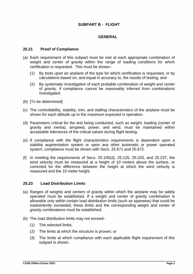
25.21 Proof of Compliance
(a) Each requirement of this subpart must be met at each appropriate combination of weight and center of gravity within the range of loading conditions for which certification is requested. This must be shown− (1) By tests upon an airplane of the type for which certification is requested, or by
calculations based on, and equal in accuracy to, the results of testing; and (2) By systematic investigation of each probable combination of weight and center
of gravity, if compliance cannot be reasonably inferred from combinations investigated.
(b) [To be determined]
(c) The controllability, stability, trim, and stalling characteristics of the airplane must be shown for each altitude up to the maximum expected in operation.
(d) Parameters critical for the test being conducted, such as weight, loading (center of gravity and inertia), airspeed, power, and wind, must be maintained within acceptable tolerances of the critical values during flight testing.
(e) If compliance with the flight characteristics requirements is dependent upon a stability augmentation system or upon any other automatic or power operated system, compliance must be shown with Secs. 25.671 and 25.672.
(f) In meeting the requirements of Secs. 25.105(d), 25.125, 25.233, and 25.237, the wind velocity must be measured at a height of 10 meters above the surface, or corrected for the difference between the height at which the wind velocity is measured and the 10 meter height.
25.23 Load Distribution Limits
(a) Ranges of weights and centers of gravity within which the airplane may be safely operated must be established. If a weight and center of gravity combination is allowable only within certain load distribution limits (such as spanwise) that could be inadvertently exceeded, these limits and the corresponding weight and center of gravity combinations must be established.
(b) The load distribution limits may not exceed− (1) The selected limits; (2) The limits at which the structure is proven; or (3) The limits at which compliance with each applicable flight requirement of this
subpart is shown.
CASR 25/Rev:5/June 2003 Page 2
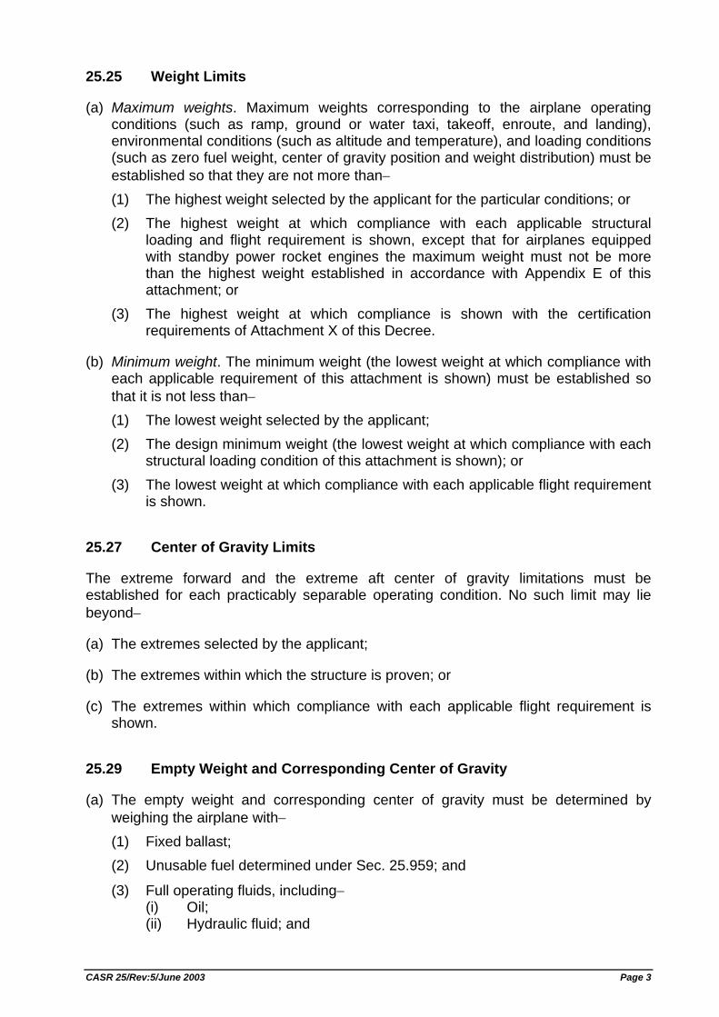
25.25 Weight Limits
(a) Maximum weights. Maximum weights corresponding to the airplane operating conditions (such as ramp, ground or water taxi, takeoff, enroute, and landing), environmental conditions (such as altitude and temperature), and loading conditions (such as zero fuel weight, center of gravity position and weight distribution) must be established so that they are not more than− (1) The highest weight selected by the applicant for the particular conditions; or (2) The highest weight at which compliance with each applicable structural
loading and flight requirement is shown, except that for airplanes equipped with standby power rocket engines the maximum weight must not be more than the highest weight established in accordance with Appendix E of this attachment; or
(3) The highest weight at which compliance is shown with the certification requirements of Attachment X of this Decree.
(b) Minimum weight. The minimum weight (the lowest weight at which compliance with each applicable requirement of this attachment is shown) must be established so that it is not less than− (1) The lowest weight selected by the applicant; (2) The design minimum weight (the lowest weight at which compliance with each
structural loading condition of this attachment is shown); or (3) The lowest weight at which compliance with each applicable flight requirement
is shown.
25.27 Center of Gravity Limits
The extreme forward and the extreme aft center of gravity limitations must be established for each practicably separable operating condition. No such limit may lie beyond−
(a) The extremes selected by the applicant;
(b) The extremes within which the structure is proven; or
(c) The extremes within which compliance with each applicable flight requirement is shown.
25.29 Empty Weight and Corresponding Center of Gravity
(a) The empty weight and corresponding center of gravity must be determined by weighing the airplane with− (1) Fixed ballast; (2) Unusable fuel determined under Sec. 25.959; and
(3) Full operating fluids, including− (i) Oil; (ii) Hydraulic fluid; and
CASR 25/Rev:5/June 2003 Page 3
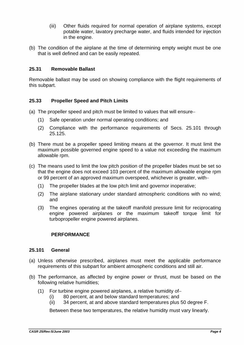
(iii) Other fluids required for normal operation of airplane systems, except potable water, lavatory precharge water, and fluids intended for injection in the engine.
(b) The condition of the airplane at the time of determining empty weight must be one that is well defined and can be easily repeated.
25.31 Removable Ballast
Removable ballast may be used on showing compliance with the flight requirements of this subpart.
25.33 Propeller Speed and Pitch Limits
(a) The propeller speed and pitch must be limited to values that will ensure− (1) Safe operation under normal operating conditions; and (2) Compliance with the performance requirements of Secs. 25.101 through
25.125.
(b) There must be a propeller speed limiting means at the governor. It must limit the maximum possible governed engine speed to a value not exceeding the maximum allowable rpm.
(c) The means used to limit the low pitch position of the propeller blades must be set so that the engine does not exceed 103 percent of the maximum allowable engine rpm or 99 percent of an approved maximum overspeed, whichever is greater, with− (1) The propeller blades at the low pitch limit and governor inoperative; (2) The airplane stationary under standard atmospheric conditions with no wind;
and (3) The engines operating at the takeoff manifold pressure limit for reciprocating
engine powered airplanes or the maximum takeoff torque limit for turbopropeller engine powered airplanes.
PERFORMANCE
25.101 General
(a) Unless otherwise prescribed, airplanes must meet the applicable performance requirements of this subpart for ambient atmospheric conditions and still air.
(b) The performance, as affected by engine power or thrust, must be based on the following relative humidities;
(1) For turbine engine powered airplanes, a relative humidity of− (i) 80 percent, at and below standard temperatures; and (ii) 34 percent, at and above standard temperatures plus 50 degree F. Between these two temperatures, the relative humidity must vary linearly.
CASR 25/Rev:5/June 2003 Page 4
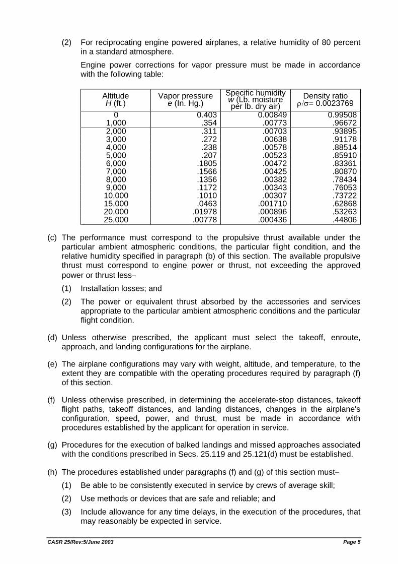
(2) For reciprocating engine powered airplanes, a relative humidity of 80 percent in a standard atmosphere. Engine power corrections for vapor pressure must be made in accordance with the following table:
Altitude H (ft.)
Vapor pressure e (In. Hg.)
Specific humidity w (Lb. moisture per lb. dry air)
Density ratio ρ/σ= 0.0023769
0 0.403 0.00849 0.995081,000 .354 .00773 .966722,000 .311 .00703 .938953,000 .272 .00638 .911784,000 .238 .00578 .885145,000 .207 .00523 .859106,000 .1805 .00472 .833617,000 .1566 .00425 .808708,000 .1356 .00382 .784349,000 .1172 .00343 .76053
10,000 .1010 .00307 .7372215,000 .0463 .001710 .6286820,000 .01978 .000896 .5326325,000 .00778 .000436 .44806
(c) The performance must correspond to the propulsive thrust available under the particular ambient atmospheric conditions, the particular flight condition, and the relative humidity specified in paragraph (b) of this section. The available propulsive thrust must correspond to engine power or thrust, not exceeding the approved power or thrust less− (1) Installation losses; and (2) The power or equivalent thrust absorbed by the accessories and services
appropriate to the particular ambient atmospheric conditions and the particular flight condition.
(d) Unless otherwise prescribed, the applicant must select the takeoff, enroute, approach, and landing configurations for the airplane.
(e) The airplane configurations may vary with weight, altitude, and temperature, to the extent they are compatible with the operating procedures required by paragraph (f) of this section.
(f) Unless otherwise prescribed, in determining the accelerate-stop distances, takeoff flight paths, takeoff distances, and landing distances, changes in the airplane's configuration, speed, power, and thrust, must be made in accordance with procedures established by the applicant for operation in service.
(g) Procedures for the execution of balked landings and missed approaches associated with the conditions prescribed in Secs. 25.119 and 25.121(d) must be established.
(h) The procedures established under paragraphs (f) and (g) of this section must− (1) Be able to be consistently executed in service by crews of average skill; (2) Use methods or devices that are safe and reliable; and (3) Include allowance for any time delays, in the execution of the procedures, that
may reasonably be expected in service.
CASR 25/Rev:5/June 2003 Page 5
25.103 Stalling Speed
(a) VS is the calibrated stalling speed, or the minimum steady flight speed, in knots, at which the airplane is controllable, with− (1) Zero thrust at the stalling speed, or, if the resultant thrust has no appreciable
effect on the stalling speed, with engines idling and throttles closed; (2) Propeller pitch controls (if applicable) in the position necessary for compliance
with paragraph (a)(1) of this section and the airplane in other respects (such as flaps and landing gear) in the condition existing in the test in which VS is being used;
(3) The weight used when VS is being used as a factor to determine compliance with a required performance standard; and
(4) The most unfavorable center of gravity allowable.
(b) The stalling speed VS is the minimum speed obtained as follows: (1) Trim the airplane for straight flight at any speed not less than 1.2 VS or more
than 1.4 VS At a speed sufficiently above the stall speed to ensure steady conditions, apply the elevator control at a rate so that the airplane speed reduction does not exceed one knot per second.
(2) Meet the flight characteristics provisions of Sec. 25.203.
25.105 Takeoff
(a) The takeoff speeds described in Sec. 25.107, the accelerate/stop distance described in Sec. 25.109, the takeoff path described in Sec. 25.111, and the takeoff distance and takeoff run described in Sec. 25.113, must be determined− (1) At each weight, altitude, and ambient temperature within the operational limits
selected by the applicant; and (2) In the selected configuration for takeoff.
(b) No takeoff made to determine the data required by this section may require exceptional piloting skill or alertness.
(c) The takeoff data must be based on− (1) A smooth, dry, hard surfaced runway, in the case of land planes and
amphibians; (2) Smooth water, in the case of seaplanes and amphibians; and (3) Smooth, dry snow, in the case of skiplanes.
(d) The takeoff data must include, within the established operational limits of the airplane, the following operational correction factors: (1) Not more than 50 percent of nominal wind components along the takeoff path
opposite to the direction of takeoff, and not less than 150 percent of nominal wind components along the takeoff path in the direction of takeoff.
(2) Effective runway gradients.
CASR 25/Rev:5/June 2003 Page 6
25.107 Takeoff speeds.
(a) V1 must be established in relation to VEF as follows: (1) VEF is the calibrated airspeed at which the critical engine is assumed to fail.
VEF must be selected by the applicant, but may not be less than VMCG determined under Sec. 25.149(e).
(2) V1, in terms of calibrated airspeed, is the takeoff decision speed selected by the applicant; however, V1 may not be less than VEF plus the speed gained with the critical engine inoperative during the time interval between the instant at which the critical engine is failed, and the instant at which the pilot recognizes and reacts to the engine failure, as indicated by the pilot's application of the first retarding means during accelerate-stop tests.
(b) V2MIN, in terms of calibrated airspeed, may not be less than−
(1) 1.2 VS for − (i) Two engine and three engine turbopropeller and reciprocating engine
powered airplanes; and (ii) Turbojet powered airplanes without provisions for obtaining a significant
reduction in the one engine inoperative power on stalling speed;
(2) 1.15 VS for− (i) Turbopropeller and reciprocating engine powered airplanes with more
than three engines; and (ii) Turbojet powered airplanes with provisions for obtaining a significant
reduction in the one engine inoperative power on stalling speed; and (3) 1.10 times VMC established under Sec. 25.149.
(c) V2, in terms of calibrated airspeed, must be selected by the applicant to provide at least the gradient of climb required by Sec. 25.121(b) but may not be less than− (1) V2MIN, and
(2) VR plus the speed increment attained (in accordance with Sec. 25.111 (c)(2)) before reaching a height of 35 feet above the takeoff surface.
(d) VMU is the calibrated airspeed at and above which the airplane can safely lift off the ground, and continue the takeoff. VMU speeds must be selected by the applicant throughout the range of thrust-to-weight ratios to be certificated. These speeds may be established from free air data if these data are verified by ground takeoff tests.
(e) VR, in terms of calibrated airspeed, must be selected in accordance with the conditions of paragraphs (e) (1) through (4) of this section:
(1) VR may not be less than− (i) V1; (ii) 105 percent of VMC; (iii) The speed (determined in accordance with Sec. 25.111(c)(2)) that
allows reaching V2 before reaching a height of 35 feet above the takeoff surface; or
(iv) A speed that, if the airplane is rotated at its maximum practicable rate, will result in a VLOF of not less than 110 percent of VMU in the all engines operating condition and not less than 105 percent of VMU determined at
CASR 25/Rev:5/June 2003 Page 7
the thrust-to-weight ratio corresponding to the one engine inoperative condition.
(2) For any given set of conditions (such as weight, configuration, and temperature), a single value of VR, obtained in accordance with this paragraph, must be used to show compliance with both the one-engine-inoperative and the all engines operating takeoff provisions.
(3) It must be shown that the one-engine-inoperative takeoff distance, using a rotation speed of 5 knots less than VR established in accordance with paragraphs (e)(1) and (2) of this section, does not exceed the corresponding one-engine-inoperative takeoff distance using the established VR. The takeoff distances must be determined in accordance with Sec. 25.113(a)(1).
(4) Reasonably expected variations in service from the established takeoff procedures for the operation of the airplane (such as over rotation of the airplane and out of trim conditions) may not result in unsafe flight characteristics or in marked increases in the scheduled takeoff distances established in accordance with Sec. 25.113(a).
(f) VLOF is the calibrated airspeed at which the airplane first becomes airborne.
25.109 Accelerate-Stop Distance
(a) The accelerate-stop distance is the greater of the following distances:
(1) The sum of the distances necessary to− (i) Accelerate the airplane from a standing start to VEF with all engines
operating; (ii) Accelerate the airplane from VEF to V1 and continue the acceleration for 2.0
seconds after V1 is reached, assuming the critical engine fails at VEF; and (iii) Come to a full stop from the point reached at the end of the acceleration
period prescribed in paragraph (a)(1)(ii) of this section, assuming that the pilot does not apply any means of retarding the airplane until that point is reached and that the critical engine is still inoperative.
(2) The sum of the distances necessary to− (i) Accelerate the airplane from a standing start to V1 and continue the
acceleration for 2.0 seconds after V1 is reached with all engines operating; and
(ii) Come to a full stop from the point reached at the end of the acceleration period prescribed in paragraph (a)(2)(i) of this section, assuming that the pilot does not apply any means of retarding the airplane until that point is reached and that all engines are still operating.
(b) Means other than wheel brakes may be used to determine the accelerate/stop distance if that means− (1) Is safe and reliable; (2) Is used so that consistent results can be expected under normal operating
conditions; and (3) Is such that exceptional skill is not required to control the airplane.
(c) The landing gear must remain extended throughout the accelerate-stop distance.
CASR 25/Rev:5/June 2003 Page 8
(d) If the accelerate-stop distance includes a stopway with surface characteristics substantially different from those of a smooth hard surfaced runway, the takeoff data must include operational correction factors for the accelerate-stop distance. The correction factors must account for the particular surface characteristics of the stopway and the variations in these characteristics with seasonal weather conditions (such as temperature, rain, snow, and ice) within the established operational limits.
25.111 Takeoff path.
(a) The takeoff path extends from a standing start to a point in the takeoff at which the airplane is 1,500 feet above the takeoff surface, or at which the transition from the takeoff to the enroute configuration is completed and a speed is reached at which compliance with Sec. 25.121(c) is shown, whichever point is higher. In addition− (1) The takeoff path must be based on the procedures prescribed in Sec.
25.101(f); (2) The airplane must be accelerated on the ground to VEF, at which point the
critical engine must be made inoperative and remain inoperative for the rest of the takeoff; and
(3) After reaching VEF, the airplane must be accelerated to V2.
(b) During the acceleration to speed V2, the nose gear may be raised off the ground at a speed not less than VR. However, landing gear retraction may not be begun until the airplane is airborne.
(c) During the takeoff path determination in accordance with paragraphs (a) and (b) of this section− (1) The slope of the airborne part of the takeoff path must be positive at each
point; (2) The airplane must reach V2 before it is 35 feet above the takeoff surface and
must continue at a speed as close as practical to, but not less than V2, until it is 400 feet above the takeoff surface;
(3) At each point along the takeoff path, starting at the point at which the airplane reaches 400 feet above the takeoff surface, the available gradient of climb may not be less than− (i) 1.2 percent for two engine airplanes; (ii) 1.5 percent for three engine airplanes; and (iii) 1.7 percent for four engine airplanes; and
(4) Except for gear retraction and propeller feathering, the airplane configuration may not be changed, and no change in power or thrust that requires action by the pilot may be made, until the airplane is 400 feet above the takeoff surface.
(d) The takeoff path must be determined by a continuous demonstrated takeoff or by synthesis from segments. If the takeoff path is determined by the segmental method− (1) The segments must be clearly defined and must be related to the distinct
changes in the configuration, power or thrust, and speed;
CASR 25/Rev:5/June 2003 Page 9
(2) The weight of the airplane, the configuration, and the power or thrust must be constant throughout each segment and must correspond to the most critical condition prevailing in the segment;
(3) The flight path must be based on the airplane's performance without ground effect; and
(4) The takeoff path data must be checked by continuous demonstrated takeoffs up to the point at which the airplane is out of ground effect and its speed is stabilized, to ensure that the path is conservative relative to the continuous path. The airplane is considered to be out of the ground effect when it reaches a height equal to its wing span.
(e) For airplanes equipped with standby power rocket engines, the takeoff path may be determined in accordance with section II of Appendix E.
25.113 Takeoff Distance and Takeoff Run
(a) Takeoff distance is the greater of− (1) The horizontal distance along the takeoff path from the start of the takeoff to
the point at which the airplane is 35 feet above the takeoff surface, determined under Sec. 25.111; or
(2) 115 percent of the horizontal distance along the take-off path, with all engines operating, from the start of the takeoff to the point at which the airplane is 35 feet above the takeoff surface, as determined by a procedure consistent with Sec. 25.111.
(b) If the takeoff distance includes a clearway, the takeoff run is the greater of− (1) The horizontal distance along the takeoff path from the start of the takeoff to a
point equidistant between the point at which VLOF is reached and the point at which the airplane is 35 feet above the takeoff surface, as determined under Sec. 25.111; or
(2) 115 percent of the horizontal distance along the takeoff path, with all engines operating, from the start of the takeoff to a point equidistant between the point at which VLOF is reached and the point at which the airplane is 35 feet above the takeoff surface, determined by a procedure consistent with Sec. 25.111.
25.115 Takeoff Flight Path
(a) The takeoff flight path begins 35 feet above the takeoff surface at the end of the takeoff distance determined in accordance with Sec. 25.113(a).
(b) The net takeoff flight path data must be determined so that they represent the actual takeoff flight paths (determined in accordance with Sec. 25.111 and with paragraph (a) of this section) reduced at each point by a gradient of climb equal to− (1) 0.8 percent for two engine airplanes; (2) 0.9 percent for three engine airplanes; and (3) 1.0 percent for four engine airplanes.
CASR 25/Rev:5/June 2003 Page 10
(c) The prescribed reduction in climb gradient may be applied as an equivalent reduction in acceleration along that part of the takeoff flight path at which the airplane is accelerated in level flight.
25.117 Climb: General
Compliance with the requirements of Secs. 25.119 and 25.121 must be shown at each weight, altitude, and ambient temperature within the operational limits established for the airplane and with the most unfavorable center of gravity for each configuration.
25.119 Landing Climb: All Engine Operating
In the landing configuration, the steady gradient of climb may not be less than 3.2 percent, with−
(a) The engines at the power or thrust that is available eight seconds after initiation of movement of the power or thrust controls from the minimum flight idle to the go-around power or thrust setting; and
(b) A climb speed of not more than 1.3 VS. [Rev. 25-2, SKEP/199/XII/96, 26 Dec. 1996, ref. FAR Amdt. 25-84]
25.121 Climb: One Engine in Operative
(a) Takeoff; landing gear extended. In the critical takeoff configuration existing along the flight path (between the points at which the airplane reaches VLOF and at which the landing gear is fully retracted) and in the configuration used in Sec. 25.111 but without ground effect, the steady gradient of climb must be positive for two engine airplanes, and not less than 0.3 percent for three engine airplanes or 0.5 percent for four engine airplanes, at VLOF and with−
(1) The critical engine inoperative and the remaining engines at the power or thrust available when retraction of the landing gear is begun in accordance with Sec. 25.111 unless there is a more critical power operating condition existing later along the flight path but before the point at which the landing gear is fully retracted; and
(2) The weight equal to the weight existing when retraction of the landing gear is begun, determined under Sec. 25.111.
(b) Takeoff; landing gear retracted. In the takeoff configuration existing at the point of the flight path at which the landing gear is fully retracted, and in the configuration used in Sec. 25.111 but without ground effect, the steady gradient of climb may not be less than 2.4 percent for two engine airplanes, 2.7 percent for three engine airplanes, and 3.0 percent for four engine airplanes, at V2 and with− (1) The critical engine inoperative, the remaining engines at the takeoff power or
thrust available at the time the landing gear is fully retracted, determined under Sec. 25.111, unless there is a more critical power operating condition existing later along the flight path but before the point where the airplane reaches a height of 400 feet above the takeoff surface; and
CASR 25/Rev:5/June 2003 Page 11
(2) The weight equal to the weight existing when the airplane's landing gear is fully retracted, determined under Sec. 25.111.
(c) Final takeoff. In the enroute configuration at the end of the takeoff path determined in accordance with Sec. 25.111, the steady gradient of climb may not be less than 1.2 percent for two engine airplanes, 1.5 percent for three engine airplanes, and 1.7 percent for four engine airplanes, at not less than 1.25 VS and with− (1) The critical engine inoperative and the remaining engines at the available
maximum continuous power or thrust; and (2) The weight equal to the weight existing at the end of the takeoff path,
determined under Sec. 25.111.
(d) Approach. In the approach configuration corresponding to the normal all engines operating procedure in which VS for this configuration does not exceed 110 percent of the VS for the related landing configuration, the steady gradient of climb may not be less than 2.1 percent for two engine airplanes, 2.4 percent for three engine airplanes, and 2.7 percent for four engine airplanes, with− (1) The critical engine inoperative, the remaining engines at the go-around power
or thrust setting; (2) The maximum landing weight; and (3) A climb speed established in connection with normal landing procedures, but
not exceeding 1.5 VS. [Rev. 25-2, SKEP/199/XII/96, 26 Dec. 1996, ref. FAR Amdt. 25-84]
25.123 Enroute Flight Paths
(a) For the enroute configuration, the flight paths prescribed in paragraphs (b) and (c) of this section must be determined at each weight, altitude, and ambient temperature, within the operating limits established for the airplane. The variation of weight along the flight path, accounting for the progressive consumption of fuel and oil by the operating engines, may be included in the computation. The flight paths must be determined at any selected speed, with− (1) The most unfavorable center of gravity; (2) The critical engines inoperative; (3) The remaining engines at the available maximum continuous power or thrust; and (4) The means for controlling the engine cooling air supply in the position that
provides adequate cooling in the hot day condition.
(b) The one engine inoperative net flight path data must represent the actual climb performance diminished by a gradient of climb of 1.1 percent for two engine airplanes, 1.4 percent for three engine airplanes, and 1.6 percent for four engine airplanes.
(c) For three- or four-engine airplanes, the two engine inoperative net flight path data must represent the actual climb performance diminished by a gradient of climb of 0.3 percent for three engine airplanes and 0.5 percent for four engine airplanes.
CASR 25/Rev:5/June 2003 Page 12
25.125 Landing
(a) The horizontal distance necessary to land and to come to a complete stop (or to a speed of approximately 3 knots for water landings) from a point 50 feet above the landing surface must be determined (for standard temperatures, at each weight, altitude, and wind within the operational limits established by the applicant for the airplane) as follows: (1) The airplane must be in the landing configuration. (2) A stabilized approach, with a calibrated airspeed of not less than 1.3 VS or
VMCL, whichever is greater, must be maintained down to the 50 foot height.
(3) Changes in configuration, power or thrust, and speed, must be made in accordance with the established procedures for service operation.
(4) The landing must be made without excessive vertical acceleration, tendency to bounce, nose over, ground loop, porpoise, or water loop.
(5) The landings may not require exceptional piloting skill or alertness.
(b) For landplanes and amphibians, the landing distance on land must be determined on a level, smooth, dry, hard surfaced runway. In addition− (1) The pressures on the wheel braking systems may not exceed those specified
by the brake manufacturer; (2) The brakes may not be used so as to cause excessive wear of brakes or tires;
and
(3) Means other than wheel brakes may be used if that means− (i) Is safe and reliable; (ii) Is used so that consistent results can be expected in service; and (iii) Is such that exceptional skill is not required to control the airplane.
(c) For seaplanes and amphibians, the landing distance on water must be determined on smooth water.
(d) For skiplanes, the landing distance on snow must be determined on smooth, dry, snow.
(e) The landing distance data must include correction factors for not more than 50 percent of the nominal wind components along the landing path opposite to the direction of landing, and not less than 150 percent of the nominal wind components along the landing path in the direction of landing.
(f) If any device is used that depends on the operation of any engine, and if the landing distance would be noticeably increased when a landing is made with that engine inoperative, the landing distance must be determined with that engine inoperative unless the use of compensating means will result in a landing distance not more than that with each engine operating. [Rev. 25-2, SKEP/199/XII/96, 26 Dec. 1996, ref. FAR Amdt. 25-84]
CASR 25/Rev:5/June 2003 Page 13
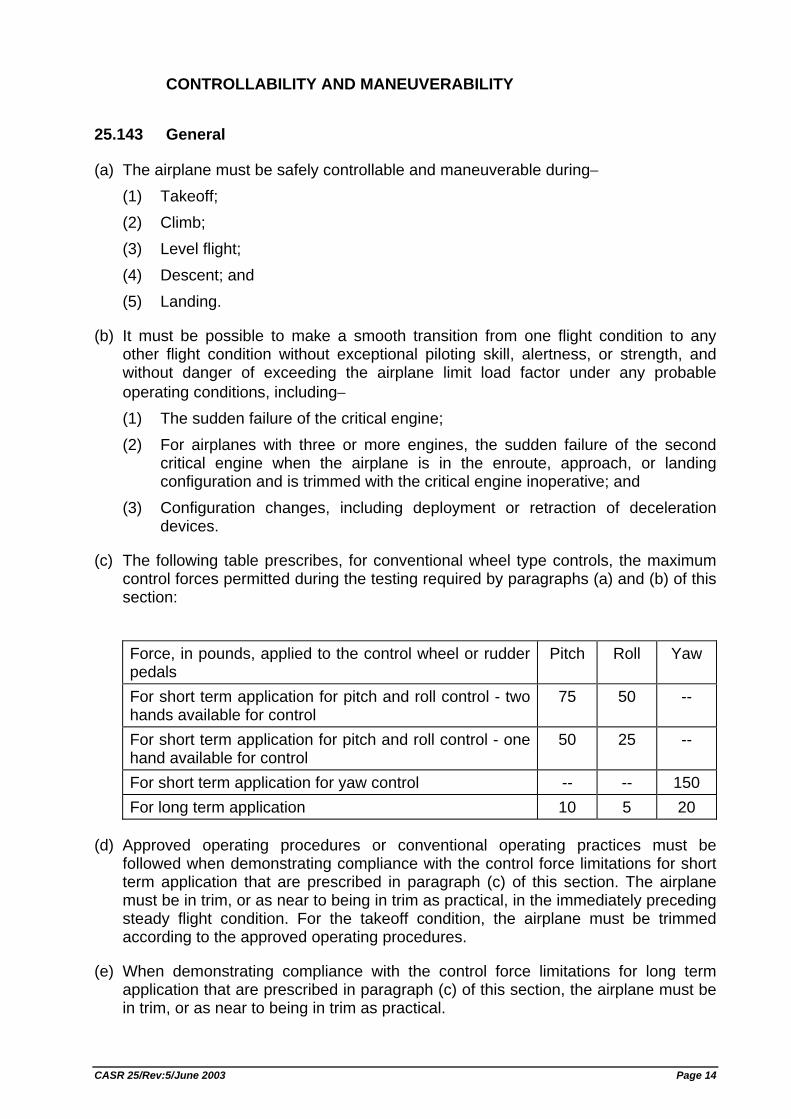
CONTROLLABILITY AND MANEUVERABILITY
25.143 General
(a) The airplane must be safely controllable and maneuverable during− (1) Takeoff; (2) Climb; (3) Level flight; (4) Descent; and (5) Landing.
(b) It must be possible to make a smooth transition from one flight condition to any other flight condition without exceptional piloting skill, alertness, or strength, and without danger of exceeding the airplane limit load factor under any probable operating conditions, including− (1) The sudden failure of the critical engine; (2) For airplanes with three or more engines, the sudden failure of the second
critical engine when the airplane is in the enroute, approach, or landing configuration and is trimmed with the critical engine inoperative; and
(3) Configuration changes, including deployment or retraction of deceleration devices.
(c) The following table prescribes, for conventional wheel type controls, the maximum control forces permitted during the testing required by paragraphs (a) and (b) of this section:
Force, in pounds, applied to the control wheel or rudder pedals
Pitch Roll Yaw
For short term application for pitch and roll control - two hands available for control
75 50 --
For short term application for pitch and roll control - one hand available for control
50 25 --
For short term application for yaw control -- -- 150 For long term application 10 5 20
(d) Approved operating procedures or conventional operating practices must be followed when demonstrating compliance with the control force limitations for short term application that are prescribed in paragraph (c) of this section. The airplane must be in trim, or as near to being in trim as practical, in the immediately preceding steady flight condition. For the takeoff condition, the airplane must be trimmed according to the approved operating procedures.
(e) When demonstrating compliance with the control force limitations for long term application that are prescribed in paragraph (c) of this section, the airplane must be in trim, or as near to being in trim as practical.
CASR 25/Rev:5/June 2003 Page 14
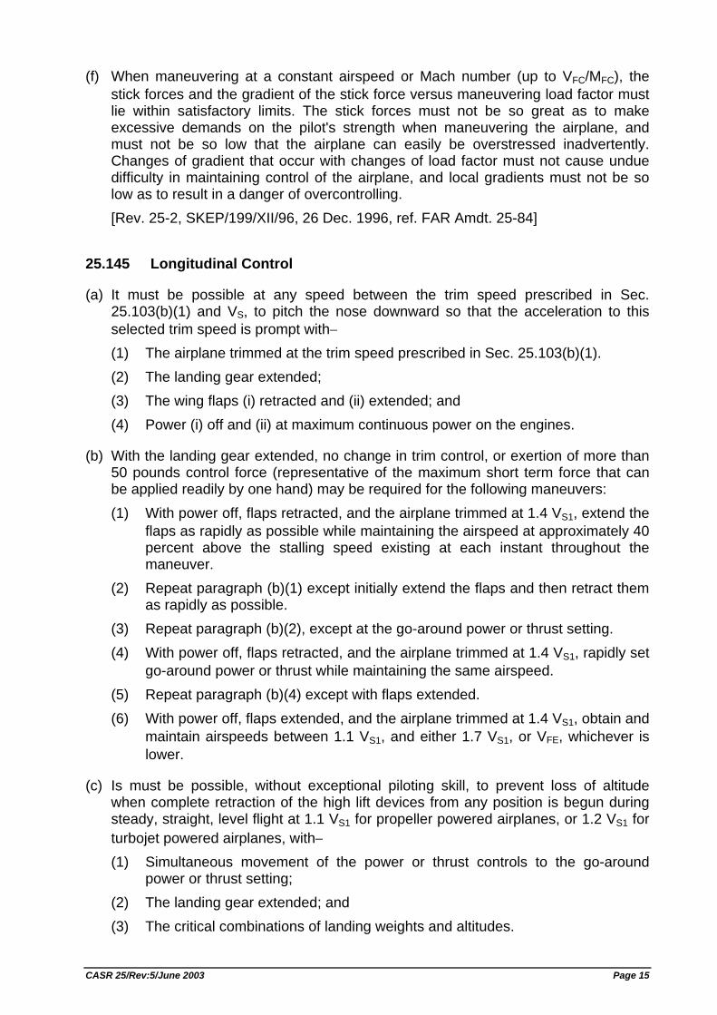
(f) When maneuvering at a constant airspeed or Mach number (up to VFC/MFC), the stick forces and the gradient of the stick force versus maneuvering load factor must lie within satisfactory limits. The stick forces must not be so great as to make excessive demands on the pilot's strength when maneuvering the airplane, and must not be so low that the airplane can easily be overstressed inadvertently. Changes of gradient that occur with changes of load factor must not cause undue difficulty in maintaining control of the airplane, and local gradients must not be so low as to result in a danger of overcontrolling. [Rev. 25-2, SKEP/199/XII/96, 26 Dec. 1996, ref. FAR Amdt. 25-84]
25.145 Longitudinal Control
(a) It must be possible at any speed between the trim speed prescribed in Sec. 25.103(b)(1) and VS, to pitch the nose downward so that the acceleration to this selected trim speed is prompt with− (1) The airplane trimmed at the trim speed prescribed in Sec. 25.103(b)(1). (2) The landing gear extended; (3) The wing flaps (i) retracted and (ii) extended; and (4) Power (i) off and (ii) at maximum continuous power on the engines.
(b) With the landing gear extended, no change in trim control, or exertion of more than 50 pounds control force (representative of the maximum short term force that can be applied readily by one hand) may be required for the following maneuvers: (1) With power off, flaps retracted, and the airplane trimmed at 1.4 VS1, extend the
flaps as rapidly as possible while maintaining the airspeed at approximately 40 percent above the stalling speed existing at each instant throughout the maneuver.
(2) Repeat paragraph (b)(1) except initially extend the flaps and then retract them as rapidly as possible.
(3) Repeat paragraph (b)(2), except at the go-around power or thrust setting. (4) With power off, flaps retracted, and the airplane trimmed at 1.4 VS1, rapidly set
go-around power or thrust while maintaining the same airspeed. (5) Repeat paragraph (b)(4) except with flaps extended. (6) With power off, flaps extended, and the airplane trimmed at 1.4 VS1, obtain and
maintain airspeeds between 1.1 VS1, and either 1.7 VS1, or VFE, whichever is lower.
(c) Is must be possible, without exceptional piloting skill, to prevent loss of altitude when complete retraction of the high lift devices from any position is begun during steady, straight, level flight at 1.1 VS1 for propeller powered airplanes, or 1.2 VS1 for turbojet powered airplanes, with− (1) Simultaneous movement of the power or thrust controls to the go-around
power or thrust setting; (2) The landing gear extended; and (3) The critical combinations of landing weights and altitudes.
CASR 25/Rev:5/June 2003 Page 15
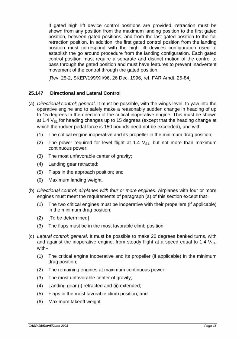
If gated high lift device control positions are provided, retraction must be shown from any position from the maximum landing position to the first gated position, between gated positions, and from the last gated position to the full retraction position. In addition, the first gated control position from the landing position must correspond with the high lift devices configuration used to establish the go around procedure from the landing configuration. Each gated control position must require a separate and distinct motion of the control to pass through the gated position and must have features to prevent inadvertent movement of the control through the gated position. [Rev. 25-2, SKEP/199/XII/96, 26 Dec. 1996, ref. FAR Amdt. 25-84]
25.147 Directional and Lateral Control
(a) Directional control; general. It must be possible, with the wings level, to yaw into the operative engine and to safely make a reasonably sudden change in heading of up to 15 degrees in the direction of the critical inoperative engine. This must be shown at 1.4 VS1 for heading changes up to 15 degrees (except that the heading change at which the rudder pedal force is 150 pounds need not be exceeded), and with− (1) The critical engine inoperative and its propeller in the minimum drag position; (2) The power required for level flight at 1.4 VS1, but not more than maximum
continuous power; (3) The most unfavorable center of gravity; (4) Landing gear retracted; (5) Flaps in the approach position; and (6) Maximum landing weight.
(b) Directional control; airplanes with four or more engines. Airplanes with four or more engines must meet the requirements of paragraph (a) of this section except that− (1) The two critical engines must be inoperative with their propellers (if applicable)
in the minimum drag position; (2) [To be determined] (3) The flaps must be in the most favorable climb position.
(c) Lateral control; general. It must be possible to make 20 degrees banked turns, with and against the inoperative engine, from steady flight at a speed equal to 1.4 VS1, with− (1) The critical engine inoperative and its propeller (if applicable) in the minimum
drag position; (2) The remaining engines at maximum continuous power; (3) The most unfavorable center of gravity; (4) Landing gear (i) retracted and (ii) extended; (5) Flaps in the most favorable climb position; and (6) Maximum takeoff weight.
CASR 25/Rev:5/June 2003 Page 16
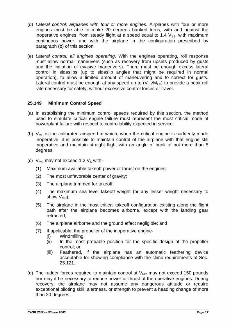
(d) Lateral control; airplanes with four or more engines. Airplanes with four or more engines must be able to make 20 degrees banked turns, with and against the inoperative engines, from steady flight at a speed equal to 1.4 VS1, with maximum continuous power, and with the airplane in the configuration prescribed by paragraph (b) of this section.
(e) Lateral control; all engines operating. With the engines operating, roll response must allow normal maneuvers (such as recovery from upsets produced by gusts and the initiation of evasive maneuvers). There must be enough excess lateral control in sideslips (up to sideslip angles that might be required in normal operation), to allow a limited amount of maneuvering and to correct for gusts. Lateral control must be enough at any speed up to (VFC/MFC) to provide a peak roll rate necessary for safety, without excessive control forces or travel.
25.149 Minimum Control Speed
(a) In establishing the minimum control speeds required by this section, the method used to simulate critical engine failure must represent the most critical mode of powerplant failure with respect to controllability expected in service.
(b) VMC is the calibrated airspeed at which, when the critical engine is suddenly made inoperative, it is possible to maintain control of the airplane with that engine still inoperative and maintain straight flight with an angle of bank of not more than 5 degrees.
(c) VMC may not exceed 1.2 VS with−
(1) Maximum available takeoff power or thrust on the engines; (2) The most unfavorable center of gravity; (3) The airplane trimmed for takeoff; (4) The maximum sea level takeoff weight (or any lesser weight necessary to
show VMC);
(5) The airplane in the most critical takeoff configuration existing along the flight path after the airplane becomes airborne, except with the landing gear retracted;
(6) The airplane airborne and the ground effect negligible; and (7) If applicable, the propeller of the inoperative engine-
(i) Windmilling; (ii) In the most probable position for the specific design of the propeller
control; or (iii) Feathered, if the airplane has an automatic feathering device
acceptable for showing compliance with the climb requirements of Sec. 25.121.
(d) The rudder forces required to maintain control at VMC may not exceed 150 pounds nor may it be necessary to reduce power or thrust of the operative engines. During recovery, the airplane may not assume any dangerous attitude or require exceptional piloting skill, alertness, or strength to prevent a heading change of more than 20 degrees.
CASR 25/Rev:5/June 2003 Page 17
(e) VMCG, the minimum control speed on the ground is the calibrated airspeed during the takeoff run at which, when the critical engine is suddenly made inoperative, it is possible to maintain control of the airplane using the rudder control alone (without the use of nosewheel steering), as limited by 150 pounds of force, and the lateral control to the extent of keeping the wings level to enable the takeoff to be safely continued using normal piloting skill. In the determination of VMCG, assuming that the path of the airplane accelerating with all engines operating is along the centerline of the runway, its path from the point at which the critical engine is made inoperative to the point at which recovery to a direction parallel to the centerline is completed may not deviate more than 30 feet laterally from the centerline at any point. VMCG must be established with− (1) The airplane in each takeoff configuration or, at the option of the applicant, in
the most critical takeoff configuration; (2) Maximum available takeoff power or thrust on the operating engines; (3) The most unfavorable center of gravity; (4) The airplane trimmed for takeoff; and (5) The most unfavorable weight in the range of takeoff weights.
(f) VMCL, the minimum control speed during approach and landing with all engines operating, is the calibrated airspeed at which, when the critical engine is suddenly made inoperative, it is possible to maintain control of the airplane with that engine still inoperative, and maintain straight flight with an angle of bank of not more than 5 degrees. VMCL must be established with−
(1) The airplane in the most critical configuration (or, at the option of the applicant, each configuration) for approach and landing with all engines operating;
(2) The most unfavorable center of gravity; (3) The airplane trimmed for approach with all engines operating; (4) The most favorable weight, or, at the option of the applicant, as a function of
weight; (5) For propeller airplanes, the propeller of the inoperative engine in the position it
achieves without pilot action, assuming the engine fails while at the power or thrust necessary to maintain a three degree approach path angle; and
(6) Go-around power or thrust setting on the operating engine(s).
(g) For airplanes with three or more engines, VMCL-2, the minimum control speed during approach and landing with one critical engine inoperative, is the calibrated airspeed at which, when a second critical engine is suddenly made inoperative, it is possible to maintain control of the airplane with both engines still inoperative, and maintain straight flight with an angle of bank of not more than 5 degrees. VMCL-2 must be established with− (1) The airplane in the most critical configuration (or, at the option of the applicant,
each configuration) for approach and landing with one critical engine inoperative;
(2) The most unfavorable center of gravity; (3) The airplane trimmed for approach with one critical engine inoperative;
CASR 25/Rev:5/June 2003 Page 18
(4) The most unfavorable weight, or, at the option of the applicant, as a function of weight;
(5) For propeller airplanes, the propeller of the more critical inoperative engine in the position it achieves without pilot action, assuming the engine fails while at the power or thrust necessary to maintain a three degree approach path angle, and the propeller of the other inoperative engine feathered;
(6) The power or thrust on the operating engine(s) necessary to maintain an approach path angle of three degrees when one critical engine is inoperative; and
(7) The power or thrust on the operating engine(s) rapidly changed, immediately after the second critical engine is made inoperative, from the power or thrust prescribed in paragraph (g)(6) of this section to− (i) Minimum power or thrust; and (ii) Go-around power or thrust setting.
(h) In demonstrations of VMCL and VMCL-2 −
(1) The rudder force may not exceed 150 pounds; (2) The airplane may not exhibit hazardous flight characteristics or require
exceptional piloting skill, alertness, or strength; (3) Lateral control must be sufficient to roll the airplane, from an initial condition of
steady flight, through an angle of 20 degrees in the direction necessary to initiate a turn away from the inoperative engine(s), in not more than 5 seconds; and
(4) For propeller airplanes, hazardous flight characteristics must not be exhibited due to any propeller position achieved when the engine fails or during any likely subsequent movements of the engine or propeller controls. [Rev. 25-2, SKEP/199/XII/96, 26 Dec. 1996, ref. FAR Amdt. 25-84]
TRIM
25.161 Trim
(a) General. Each airplane must meet the trim requirements of this section after being trimmed, and without further pressure upon, or movement of, either the primary controls or their corresponding trim controls by the pilot or the automatic pilot.
(b) Lateral and directional trim. The airplane must maintain lateral and directional trim with the most adverse lateral displacement of the center of gravity within the relevant operating limitations, during normally expected conditions of operation (including operation at any speed from 1.4 VS1 to VMO/MMO).
(c) Longitudinal trim. The airplane must maintain longitudinal trim during− (1) A climb with maximum continuous power at a speed not more than 1.4 VS1,
with the landing gear retracted, and the flaps (i) retracted and (ii) in the takeoff position;
(2) A glide with power off at a speed not more than 1.4 VS1, with the landing gear extended, the wing flaps (i) retracted and (ii) extended, the most unfavorable
CASR 25/Rev:5/June 2003 Page 19
center of gravity position approved for landing with the maximum landing weight, and with the most unfavorable center of gravity position approved for landing regardless of weight; and
(3) Level flight at any speed from 1.4 VS1, to (VMO/MMO), with the landing gear and flaps retracted, and from 1.4 VS1 to VLE with the landing gear extended.
(d) Longitudinal, directional, and lateral trim. The airplane must maintain longitudinal, directional, and lateral trim (and for the lateral trim, the angle of bank may not exceed five degrees) at 1.4 VS1 during climbing flight with− (1) The critical engine inoperative; (2) The remaining engines at maximum continuous power; and (3) The landing gear and flaps retracted.
(e) Airplanes with four or more engines. Each airplane with four or more engines must maintain trim in rectilinear flight− (1) At the climb speed, configuration, and power required by Sec. 25.123(a) for
the purpose of establishing the rate of climb; (2) With the most unfavorable center of gravity position; and (3) At the weight at which the two engine inoperative climb is equal to at least
0.013 VSO2 at an altitude of 5,000 feet.
STABILITY
25.171 General
The airplane must be longitudinally, directionally, and laterally stable in accordance with the provisions of Secs. 25.173 through 25.177. In addition, suitable stability and control feel (static stability) is required in any condition normally encountered in service, if flight tests show it is necessary for safe operation.
25.173 Static Longitudinal Stability
Under the conditions specified in Sec. 25.175, the characteristics of the elevator control forces (including friction) must be as follows:
(a) A pull must be required to obtain and maintain speeds below the specified trim speed, and a push must be required to obtain and maintain speeds above the specified trim speed. This must be shown at any speed that can be obtained except speeds higher than the landing gear or wing flap operating limit speeds or (VFC/MFC), whichever is appropriate, or lower than the minimum speed for steady unstalled flight.
(b) The airspeed must return to within 10 percent of the original trim speed for the climb, approach, and landing conditions specified in Sec. 25.175 (a), (c), and (d), and must return to within 7.5 percent of the original trim speed for the cruising condition specified in Sec. 25.175(b), when the control force is slowly released from any speed within the range specified in paragraph (a) of this section.
CASR 25/Rev:5/June 2003 Page 20
(c) The average gradient of the stable slope of the stick force versus speed curve may not be less than 1 pound for each 6 knots.
(d) Within the free return speed range specified in paragraph (b) of this section, it is permissible for the airplane, without control forces, to stabilize on speeds above or below the desired trim speeds if exceptional attention on the part of the pilot is not required to return to and maintain the desired trim speed and altitude.
25.175 Demonstration of Static Longitudinal Stability
Static longitudinal stability must be shown as follows:
(a) Climb. The stick force curve must have a stable slope at speeds between 85 and 115 percent of the speed at which the airplane−
(1) Is trimmed, with− (i) Wing flaps retracted; (ii) Landing gear retracted; (iii) Maximum takeoff weight; and (iv) 75 percent of maximum continuous power for reciprocating engines or
the maximum power or thrust selected by the applicant as an operating limitation for use during climb for turbine engines; and
(2) Is trimmed at the speed for best rate of climb except that the speed need not be less than 1.4 VS1.
(b) Cruise. Static longitudinal stability must be shown in the cruise condition as follows: (1) With the landing gear retracted at high speed, the stick force curve must have
a stable slope at all speeds within a range which is the greater of 15 percent of the trim speed plus the resulting free return speed range, or 50 knots plus the resulting free return speed range, above and below the trim speed (except that the speed range need not include speeds less than 1.4 VS1, nor speeds greater than (VFC/MFC), nor speeds that require a stick force of more than 50 pounds), with− (i) The wing flaps retracted; (ii) The center of gravity in the most adverse position (see Sec. 25.27); (iii) The most critical weight between the maximum takeoff and maximum
landing weights; (iv) 75 percent of maximum continuous power for reciprocating engines or
for turbine engines, the maximum cruising power selected by the applicant as an operating limitation (see Sec. 25.1521), except that the power need not exceed that required at (VMO/MMO); and
(v) The airplane trimmed for level flight with the power required in paragraph (b)(1)(iv) of this section.
(2) With the landing gear retracted at low speed, the stick force curve must have a stable slope at all speeds within a range which is the greater of 15 percent of the trim speed plus the resulting free return speed range, or 50 knots plus the resulting free return speed range, above and below the trim speed (except that the speed range need not include speeds less than 1.4 VS1, nor speeds greater than the minimum speed of the applicable speed range prescribed in paragraph (b)(1), nor speeds that require a stick force of more than 50 pounds), with−
CASR 25/Rev:5/June 2003 Page 21
(i) Wing flaps, center of gravity position, and weight as specified in paragraph (b)(1) of this section;
(ii) Power required for level flight at a speed equal to VMO + (1.4VS1)/2; and (iii) The airplane trimmed for level flight with the power required in
paragraph (b)(2)(ii) of this section. (3) With the landing gear extended, the stick force curve must have a stable slope
at all speeds within a range which is the greater of 15 percent of the trim speed plus the resulting free return speed range, or 50 knots plus the resulting free return speed range, above and below the trim speed (except that the speed range need not include speeds less than 1.4 VS1, nor speeds greater than VLE, nor speeds that require a stick force of more than 50 pounds), with− (i) Wing flap, center of gravity position, and weight as specified in
paragraph (b)(1) of this section; (ii) 75 percent of maximum continuous power for reciprocating engines or,
for turbine engines, the maximum cruising power selected by the applicant as an operating limitation, except that the power need not exceed that required for level flight at VLE; and
(iii) The aircraft trimmed for level flight with the power required in paragraph (b)(3)(ii) of this section.
(c) Approach. The stick force curve must have a stable slope at speeds between 1.1 VS1 and 1.8 VS1, with−
(1) Wing flaps in the approach position; (2) Landing gear retracted; (3) Maximum landing weight; and (4) The airplane trimmed at 1.4 VS1 with enough power to maintain level flight at
this speed.
(d) Landing. The stick force curve must have a stable slope, and the stick force may not exceed 80 pounds, at speeds between 1.1 VS0 and 1.3 VS0 with−
(1) Wing flaps in the landing position; (2) Landing gear extended; (3) Maximum landing weight; (4) Power or thrust off on the engines; and (5) The airplane trimmed at 1.4 VS0 with power or thrust off.
25.177 Static Directional and Lateral Stability
(a) [To be determined]
(b) [To be determined]
(c) In straight, steady sideslips, the aileron and rudder control movements and forces must be substantially proportional to the angle of sideslip in a stable sense; and the factor of proportionality must lie between limits found necessary for safe operation throughout the range of sideslip angles appropriate to the operation of the airplane. At greater angles, up to the angle at which full rudder is used or a rudder force of
CASR 25/Rev:5/June 2003 Page 22
180 pounds is obtained, the rudder pedal forces may not reverse; and increased rudder deflection must be needed for increased angles of sideslip. Compliance with this paragraph must be demonstrated for all landing gear and flap positions and symmetrical power conditions at speeds from 1.2 VS1 to VFE, VLE, or (VFC/MFC), as appropriate.
(d) The rudder gradients must meet the requirements of paragraph (c) at speeds between (VMO/MMO) and (VFC/MFC) except that the dihedral effect (aileron deflection opposite the corresponding rudder input) may be negative provided the divergence is gradual, easily recognized, and easily controlled by the pilot.
25.181 Dynamic Stability
(a) Any short period oscillation, not including combined lateral/directional oscillations, occurring between 1.2 VS and maximum allowable speed appropriate to the configuration of the airplane must be heavily damped with the primary controls− (1) Free; and (2) In a fixed position.
(b) Any combined lateral/directional oscillations ("Dutch roll") occurring between 1.2 VS and maximum allowable speed appropriate to the configuration of the airplane must be positively damped with controls free, and must be controllable with normal use of the primary controls without requiring exceptional pilot skill.
STALLS
25.201 Stall Demonstration
(a) Stalls must be shown in straight flight and in 30 degree banked turns with− (1) Power off; and (2) The power necessary to maintain level flight at 1.6 VS1 (where V S1
corresponds to the stalling speed with flaps in the approach position, the landing gear retracted, and maximum landing weight).
(b) In each condition required by paragraph (a) of this section, it must be possible to meet the applicable requirements of § 25.203 with− (1) Flaps, landing gear, and deceleration devices in any likely combination of
positions approved for operation; (2) Representative weights within the range for which certification is requested; (3) The most adverse center of gravity for recovery; and (4) The airplane trimmed for straight flight at the speed prescribed in §
25.103(b)(1).
(c) The following procedures must be used to show compliance with § 25.203; (1) Starting at a speed sufficiently above the stalling speed to ensure that a
steady rate of speed reduction can be established, apply the longitudinal
CASR 25/Rev:5/June 2003 Page 23
control so that the speed reduction does not exceed one knot per second until the airplane is stalled.
(2) In addition, for turning flight stalls, apply the longitudinal control to achieve airspeed deceleration rates up to 3 knots per second.
(3) As soon as the airplane is stalled, recover by normal recovery techniques.
(d) The airplane is considered stalled when the behavior of the airplane gives the pilot a clear and distinctive indication of an acceptable nature that the airplane is stalled. Acceptable indications of a stall, occurring either individually or in combination, are− (1) A nose-down pitch that cannot be readily arrested; (2) Buffeting, of a magnitude and severity that is a strong and effective deterrent
to further speed reduction; or (3) The pitch control reaches the aft stop and no further increase in pitch attitude
occurs when the control is held full aft for a short time before recovery is initiated. [Rev. 25-2, SKEP/199/XII/96, 26 Dec. 1996, ref. FAR Amdt. 25-84]
25.203 Stall Characteristics
(a) It must be possible to produce and to correct roll and yaw by unreversed use of the aileron and rudder controls, up to the time the airplane is stalled. No abnormal nose up pitching may occur. The longitudinal control force must be positive up to and throughout the stall. In addition, it must be possible to promptly prevent stalling and to recover from a stall by normal use of the controls.
(b) For level wing stalls, the roll occurring between the stall and the completion of the recovery may not exceed approximately 20 degrees.
(c) For turning flight stalls, the action of the airplane after the stall may not be so violent or extreme as to make it difficult, with normal piloting skill, to effect a prompt recovery and to regain control of the airplane. The maximum bank angle that occurs during the recovery may not exceed− (1) Approximately 60 degrees in the original direction of the turn, or 30 degrees in
the opposite direction, for deceleration rates up to 1 knot per second; and (2) Approximately 90 degrees in the original direction of the turn, or 60 degrees in
the opposite direction, for deceleration rates in excess of 1 knot per second. [Rev. 25-2, SKEP/199/XII/96, 26 Dec. 1996, ref. FAR Amdt. 25-84]
25.207 Stall Warning
(a) Stall warning with sufficient margin to prevent inadvertent stalling with the flaps and landing gear in any normal position must be clear and distinctive to the pilot in straight and turning flight.
(b) The warning may be furnished either through the inherent aerodynamic qualities of the airplane or by a device that will give clearly distinguishable indications under expected conditions of flight. However, a visual stall warning device that requires the attention of the crew within the cockpit is not acceptable by itself. If a warning
CASR 25/Rev:5/June 2003 Page 24
device is used, it must provide a warning in each of the airplane configurations prescribed in paragraph (a) of this section at the speed prescribed in paragraph (c) of this section.
(c) The stall warning must begin at a speed exceeding the stalling speed (i.e., the speed at which the airplane stalls or the minimum speed demonstrated, whichever is applicable under the provisions of Sec. 25.201(d)) by seven percent or at any lesser margin if the stall warning has enough clarity, duration, distinctiveness, or similar properties.
GROUND AND WATER HANDLING CHARACTERISTICS
25.231 Longitudinal Stability and Control
(a) Landplanes may have no uncontrollable tendency to nose over in any reasonably expected operating condition or when rebound occurs during landing or takeoff. In addition− (1) Wheel brakes must operate smoothly and may not cause any undue tendency
to nose over; and (2) If a tail wheel landing gear is used, it must be possible, during the takeoff
ground run on concrete, to maintain any altitude up to thrust line level, at 80 percent of VS1
(b) For seaplanes and amphibians, the most adverse water conditions safe for takeoff, taxiing, and landing, must be established.
25.233 Directional Stability and Control
(a) There may be no uncontrollable ground looping tendency in 90 degree crosswinds, up to a wind velocity of 20 knots or 0.2 VS0, whichever is greater, except that the wind velocity need not exceed 25 knots. At any speed at which the airplane may be expected to be operated on the ground. This may be shown while establishing the 90 degree cross component of wind velocity required by Sec. 25.237.
(b) Landplanes must be satisfactorily controllable, without exceptional piloting skill or alertness, in power off landings at normal landing speed, without using brakes or engine power to maintain a straight path. This may be shown during power off landings made in conjunction with other tests.
(c) The airplane must have adequate directional control during taxiing. This may be shown during taxiing prior to takeoffs made in conjunction with other tests.
25.235 Taxiing Condition
The shock absorbing mechanism may not damage the structure of the airplane when the airplane is taxied on the roughest ground that may reasonably be expected in normal operation.
CASR 25/Rev:5/June 2003 Page 25
25.237 Wind Velocities
(a) For landplanes and amphibians, a 90-degree cross component of wind velocity, demonstrated to be safe for takeoff and landing, must be established for dry runways and must be at least 20 knots or 0.2 VS0, whichever is greater, except that it need not exceed 25 knots.
(b) For seaplanes and amphibians, the following applies: (1) A 90-degree cross component of wind velocity, up to which takeoff and landing
is safe under all water conditions that may reasonably be expected in normal operation, must be established and must be at least 20 knots or 0.2 VS0, whichever is greater, except that it need not exceed 25 knots.
(2) A wind velocity, for which taxiing is safe in any direction under all water conditions that may reasonably be expected in normal operation, must be established and must be at least 20 knots or 0.2 VS0, whichever is greater, except that it need not exceed 25 knots.
25.239 Spray Characteristics, Control, and Stability on Water
(a) For seaplanes and amphibians, during takeoff, taxiing, and landing, and in the conditions set forth in paragraph (b) of this section, there may be no− (1) Spray characteristics that would impair the pilot's view, cause damage, or
result in the taking in of an undue quantity of water; (2) Dangerously uncontrollable porpoising, bounding, or swinging tendency; or (3) Immersion of auxiliary floats or sponsons, wing tips, propeller blades, or other
parts not designed to withstand the resulting water loads.
(b) Compliance with the requirements of paragraph (a) of this section must be shown− (1) In water conditions, from smooth to the most adverse condition established in
accordance with Sec. 25.231; (2) In wind and crosswind velocities, water currents, and associated waves and
swells that may reasonably be expected in operation on water; (3) At speeds that may reasonably be expected in operation on water; (4) With sudden failure of the critical engine at any time while on water; and (5) At each weight and center of gravity position, relevant to each operating
condition, within the range of loading conditions for which certification is requested.
(c) In the water conditions of paragraph (b) of this section, and in the corresponding wind conditions, the seaplane or amphibian must be able to drift for five minutes with engines inoperative, aided, if necessary, by a sea anchor.
CASR 25/Rev:5/June 2003 Page 26
MISCELLANEOUS FLIGHT REQUIREMENTS
25.251 Vibration and Buffeting
(a) The airplane must be demonstrated in flight to be free from any vibration and buffeting that would prevent continued safe flight in any likely operating condition.
(b) Each part of the airplane must be demonstrated in flight to be free from excessive vibration under any appropriate speed and power conditions up to VDF/MDF. The maximum speeds shown must be used in establishing the operating limitations of the airplane in accordance with Sec. 25.1505.
(c) Except as provided in paragraph (d) of this section, there may be no buffeting condition, in normal flight, including configuration changes during cruise, severe enough to interfere with the control of the airplane, to cause excessive fatigue to the crew, or to cause structural damage. Stall warning buffeting within these limits is allowable.
(d) There may be no perceptible buffeting condition in the cruise configuration in straight flight at any speed up to VMO/MMO, except that stall warning buffeting is allowable.
(e) For an airplane with MD greater than 0.6 or with a maximum operating altitude greater than 25,000 feet, the positive maneuvering load factors at which the onset of perceptible buffeting occurs must be determined with the airplane in the cruise configuration for the ranges of airspeed or Mach number, weight, and altitude for which the airplane is to be certificated. The envelopes of load factor, speed, altitude, and weight must provide a sufficient range of speeds and load factors for normal operations. Probable inadvertent excursions beyond the boundaries of the buffet onset envelopes may not result in unsafe conditions. [Rev. 25-1, KM.7 Year 1996, 15 Feb. 1996; ref. FAR Amdt. 25-77]
25.253 High Speed Characteristics
(a) Speed increase and recovery characteristics. The following speed increase and recovery characteristics must be met: (1) Operating conditions and characteristics likely to cause inadvertent speed
increases (including upsets in pitch and roll) must be simulated with the airplane trimmed at any likely cruise speed up to (VMO/MMO). These conditions and characteristics include gust upsets, inadvertent control movements, low stick force gradient in relation to control friction, passenger movement, leveling off from climb, and descent from Mach to airspeed limit altitudes.
(2) Allowing for pilot reaction time after effective inherent or artificial speed warning occurs, it must be shown that the airplane can be recovered to a normal attitude and its speed reduced to (VMO/MMO), without− (i) Exceptional piloting strength or skill; (ii) Exceeding (VD/MD), (VDF/MDF), or the structural limitations; and (iii) Buffeting that would impair the pilot's ability to read the instruments or
control the airplane for recovery.
CASR 25/Rev:5/June 2003 Page 27
(3) With the airplane trimmed at any speed up to (VMO/MMO), there must be no reversal of the response to control input about any axis at any speed up to (VDF/MDF). Any tendency to pitch, roll, or yaw must be mild and readily controllable, using normal piloting techniques. When the airplane is trimmed at (VMO/MMO), the slope of the elevator control force versus speed curve need not be stable at speeds greater than (VFC/MFC), but there must be a push force at all speeds up to (VDF/MDF) and there must be no sudden or excessive reduction of elevator control force as (VDF/MDF) is reached.
(b) Maximum speed for stability characteristics, VFC/MFC. VFC/MFC is the maximum speed at which the requirements of §§ 25.143(f), 25.147(e), 25.175(b)(1), 25.177, and 25.181 must be met with flaps and landing gear retracted. It may not be less than a speed midway between VMO/MMO and VDF/MDF, except that for altitudes where Mach number is the limiting factor, MFC need not exceed the Mach number at which effective speed warning occurs. [Rev. 25-2, SKEP/199/XII/96, 26 Dec. 1996, ref. FAR Amdt. 25-84]
25.255 Out-of-trim Characteristics
(a) From an initial condition with the airplane trimmed at cruise speeds up to (VMO/MMO), the airplane must have satisfactory maneuvering stability and controllability with the degree of out of trim in both the airplane nose up and nose down directions, which results from the greater of− (1) A three second movement of the longitudinal trim system at its normal rate for
the particular flight condition with no aerodynamic load (or an equivalent degree of trim for airplanes that do not have a power operated trim system), except as limited by stops in the trim system, including those required by Sec. 25.655(b) for adjustable stabilizers; or
(2) The maximum mistrim that can be sustained by the autopilot while maintaining level flight in the high speed cruising condition.
(b) In the out of trim condition specified in paragraph (a) of this section, when the normal acceleration is varied from +1 g to the positive and negative values specified in paragraph (c) of this section− (1) The stick force vs. g curve must have a positive slope at any speed up to and
including (VFC/MFC); and
(2) At speeds between (VFC/MFC) and (VDF/MDF) the direction of the primary longitudinal control force may not reverse.
(c) Except as provided in paragraphs (d) and (e) of this section, compliance with the provisions of paragraph (a) of this section must be demonstrated in flight over the acceleration range−
(1) −1 g to +2.5 g; or
(2) 0 g to 2.0 g, and extrapolating by an acceptable method to −1 g and +2.5 g.
(d) If the procedure set forth in paragraph (c)(2) of this section is used to demonstrate compliance and marginal conditions exist during flight test with regard to reversal of primary longitudinal control force, flight tests must be accomplished from the normal
CASR 25/Rev:5/June 2003 Page 28
acceleration at which a marginal condition is found to exist to the applicable limit specified in paragraph (b)(1) of this section.
(e) During flight tests required by paragraph (a) of this section, the limit maneuvering load factors prescribed in Secs. 25.333(b) and 25.337, and the maneuvering load factors associated with probable inadvertent excursions beyond the boundaries of the buffet onset envelopes determined under Sec. 25.251(e), need not be exceeded. In addition, the entry speeds for flight test demonstrations at normal acceleration values less than 1 g must be limited to the extent necessary to accomplish a recovery without exceeding (VDF/MDF).
(f) In the out of trim condition specified in paragraph (a) of this section, it must be possible from an overspeed condition at (VDF/MDF) to produce at least 1.5 g for recovery by applying not more than 125 pounds of longitudinal control force using either the primary longitudinal control alone or the primary longitudinal control and the longitudinal trim system. If the longitudinal trim is used to assist in producing the required load factor, it must be shown at (VDF/MDF) that the longitudinal trim can be actuated in the airplane nose up direction with the primary surface loaded to correspond to the least of the following airplane nose up control forces: (1) The maximum control forces expected in service as specified in Secs. 25.301
and 25.397. (2) The control force required to produce 1.5g. (3) The control force corresponding to buffeting or other phenomena of such
intensity that it is a strong deterrent to further application of primary longitudinal control force.
CASR 25/Rev:5/June 2003 Page 29
SUBPART C - STRUCTURE
GENERAL
25.301 Loads
(a) Strength requirements are specified in terms of limit loads (the maximum loads to be expected in service) and ultimate loads (limit loads multiplied by prescribed factors of safety). Unless otherwise provided, prescribed loads are limit loads.
(b) Unless otherwise provided, the specified air, ground, and water loads must be placed in equilibrium with inertia forces, considering each item of mass in the airplane. These loads must be distributed to conservatively approximate or closely represent actual conditions. Methods used to determine load intensities and distribution must be validated by flight load measurement unless the methods used for determining those loading conditions are shown to be reliable.
(c) If deflections under load would significantly change the distribution of external or internal loads, this redistribution must be taken into account.
25.303 Factor of Safety
Unless otherwise specified, a factor of safety of 1.5 must be applied to the prescribed limit load which are considered external loads on the structure. When a loading condition is prescribed in terms of ultimate loads, a factor of safety need not be applied unless otherwise specified.
25.305 Strength and Deformation
(a) The structure must be able to support limit loads without detrimental permanent deformation. At any load up to limit loads, the deformation may not interfere with safe operation.
(b) The structure must be able to support ultimate loads without failure for at least 3 seconds. However, when proof of strength is shown by dynamic tests simulating actual load conditions, the 3 second limit does not apply. Static tests conducted to ultimate load must include the ultimate deflections and ultimate deformation induced by the loading. When analytical methods are used to show compliance with the ultimate load strength requirements, it must be shown that− (1) The effects of deformation are not significant; (2) The deformations involved are fully accounted for in the analysis; or (3) The methods and assumptions used are sufficient to cover the effects of these
deformations.
(c) Where structural flexibility is such that any rate of load application likely to occur in the operating conditions might produce transient stresses appreciably higher than those corresponding to static loads, the effects of this rate of application must be considered.
CASR 25/Rev:5/June 2003 Page 30
(d) [Reserved]
(e) The airplane must be designed to withstand any vibration and buffeting that might occur in any likely operating condition up to VD/MD, including stall and probable inadvertent excursions beyond the boundaries of the buffet onset envelope. This must be shown by analysis, flight tests, or other tests found necessary by the Director General.
(f) Unless shown to extremely improbable, the airplane must be designed to withstand any forced structural vibration resulting from any failure, malfunction or adverse condition in the flight control system. These must be considered limit loads and must be investigated at airspeeds up to VC/MC.
[Rev. 25-1, KM.7 Year 1996, 15 Feb. 1996, ref. FAR Amdt. 25-77; Rev. 25-2, SKEP/199/XII/96, 26 Dec. 1996, ref. FAR Amdt. 25-86]
25.307 Proof of Structure
(a) Compliance with the strength and deformation requirements of this subpart must be shown for each critical loading condition. Structural analysis may be used only if the structure conforms to that for which experience has shown this method to be reliable. The Director General may require ultimate load tests in cases where limit load tests may be inadequate.
(b) [To be determined].
(c) [To be determined].
(d) When static or dynamic tests are used to show compliance with the requirements of Sec. 25.305(b) for flight structures, appropriate material correction factors must be applied to the test results, unless the structure, or part thereof, being tested has features such that a number of elements contribute to the total strength of the structure and the failure of one element results in the redistribution of the load through alternate load paths.
FLIGHT LOADS
25.321 General
(a) Flight load factors represent the ratio of the aerodynamic force component (acting normal to the assumed longitudinal axis of the airplane) to the weight of the airplane. A positive load factor is one in which the aerodynamic force acts upward with respect to the airplane.
(b) Considering compressibility effects at each speed, compliance with the flight load requirements of this subpart must be shown− (1) At each critical altitude within the range of altitudes selected by the applicant; (2) At each weight from the design minimum weight to the design maximum
weight appropriate to each particular flight load condition; and
CASR 25/Rev:5/June 2003 Page 31
(3) For each required altitude and weight, for any practicable distribution of disposable load within the operating limitations recorded in the Airplane Flight Manual.
(c) Enough points on and within the boundaries of the design envelope must be investigated to ensure that the maximum load for each part of the airplane structure is obtained.
(d) The significant forces acting on the airplane must be placed in equilibrium in a rational or conservative manner. The linear inertia forces must be considered in equilibrium with the thrust and all aerodynamic loads, while the angular (pitching) inertia forces must be considered in equilibrium with thrust and all aerodynamic moments, including moments due to loads on components such as tail surfaces and nacelles. Critical thrust values in the range from zero to maximum continuous thrust must be considered. [Rev. 25-2, SKEP/199/XII/96, 26 Dec. 1996, ref. FAR Amdt. 25-86]
FLIGHT MANEUVER AND GUST CONDITIONS
25.331 Symmetric Maneuvering Conditions
(a) Procedure. For the analysis of the maneuvering flight conditions specified in paragraphs (b) and (c) of this section, the following provisions apply: (1) Where sudden displacement of a control is specified, the assumed rate of
control surface displacement may not be less than the rate that could be applied by the pilot through the control system.
(2) In determining elevator angles and chordwise load distribution in the maneuvering conditions of paragraphs (b) and (c) of this section, the effect of corresponding pitching velocities must be taken into account. The in-trim and out-of-trim flight conditions specified in § 25.255 must be considered.
(b) Maneuvering balanced conditions. Assuming the airplane to be in equilibrium with zero pitching acceleration, the maneuvering conditions A through I on the maneuvering envelope in Sec. 25.333(b) must be investigated.
(c) Pitch maneuver conditions. The conditions specified in paragraphs (c)(1) and (2) of this section must be investigated. The movement of the pitch control surfaces may be adjusted to take into account limitations imposed by the maximum pilot effort specified by § 25.397(b), control system stops and any indirect effect imposed by limitations in the output side of the control system (for example, stalling torque or maximum rate obtainable by a power control system.) (1) Maximum pitch control displacement at VA. The airplane is assumed to be
flying in steady level flight (point A1, § 25.333(b)) and the cockpit pitch control is suddenly moved to obtain extreme nose up pitching acceleration. In defining the tail load, the response of the airplane must be taken into account. Airplane loads that occur subsequent to the time when normal acceleration at the c.g. exceeds the positive limit maneuvering load factor (at point A2 in § 25.333(b)), or the resulting tailplane normal load reaches its maximum, whichever occurs first, need not be considered.
CASR 25/Rev:5/June 2003 Page 32
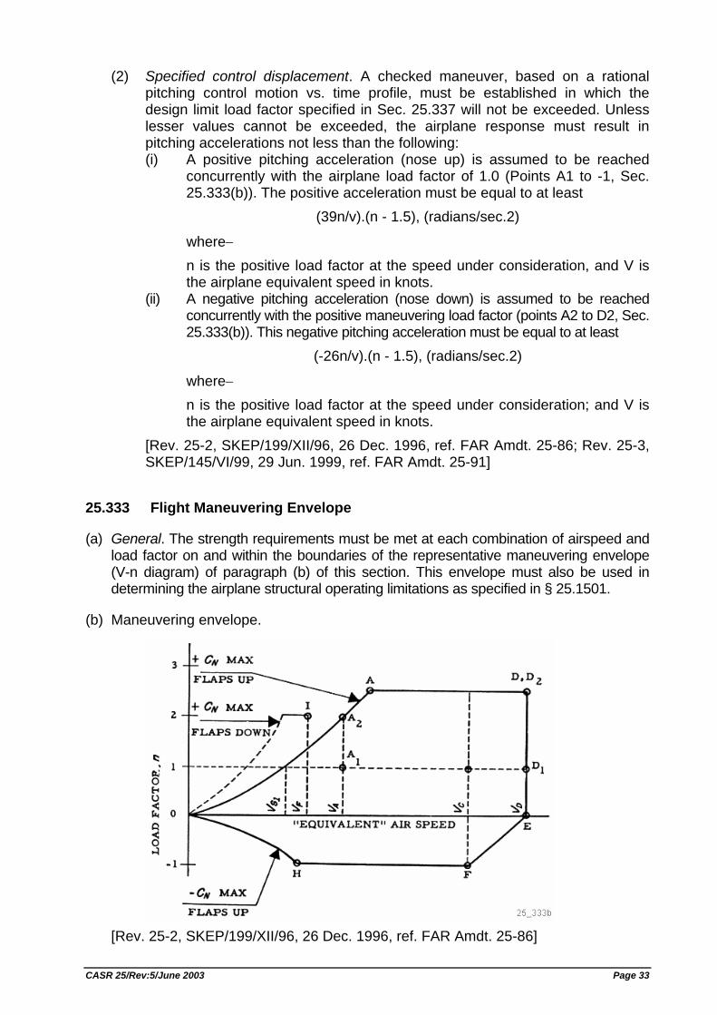
(2) Specified control displacement. A checked maneuver, based on a rational pitching control motion vs. time profile, must be established in which the design limit load factor specified in Sec. 25.337 will not be exceeded. Unless lesser values cannot be exceeded, the airplane response must result in pitching accelerations not less than the following: (i) A positive pitching acceleration (nose up) is assumed to be reached
concurrently with the airplane load factor of 1.0 (Points A1 to -1, Sec. 25.333(b)). The positive acceleration must be equal to at least
(39n/v).(n - 1.5), (radians/sec.2)
where− n is the positive load factor at the speed under consideration, and V is the airplane equivalent speed in knots.
(ii) A negative pitching acceleration (nose down) is assumed to be reached concurrently with the positive maneuvering load factor (points A2 to D2, Sec. 25.333(b)). This negative pitching acceleration must be equal to at least
(-26n/v).(n - 1.5), (radians/sec.2)
where− n is the positive load factor at the speed under consideration; and V is the airplane equivalent speed in knots.
[Rev. 25-2, SKEP/199/XII/96, 26 Dec. 1996, ref. FAR Amdt. 25-86; Rev. 25-3, SKEP/145/VI/99, 29 Jun. 1999, ref. FAR Amdt. 25-91]
25.333 Flight Maneuvering Envelope
(a) General. The strength requirements must be met at each combination of airspeed and load factor on and within the boundaries of the representative maneuvering envelope (V-n diagram) of paragraph (b) of this section. This envelope must also be used in determining the airplane structural operating limitations as specified in § 25.1501.
(b) Maneuvering envelope.
[Rev. 25-2, SKEP/199/XII/96, 26 Dec. 1996, ref. FAR Amdt. 25-86]
CASR 25/Rev:5/June 2003 Page 33
25.335 Design Airspeeds
The selected design airspeeds are equivalent airspeeds (EAS). Estimated values of VS0 and VS1 must be conservative.
(a) Design cruising speed, VC. For VC, the following apply:
(1) The minimum value of VC must be sufficiently greater than VB to provide for inadvertent speed increases likely to occur as a result of severe atmospheric turbulence.
(2) Except as provided in § 25.335(d)(2), VC may not be less than VB + 1.32 UREF (with UREF as specified in § 25.341(a)(5)(i)). However VC need not exceed the maximum speed in level flight at maximum continuous power for the corresponding altitude.
(3) At altitudes where VD is limited by Mach number, VC may be limited to a selected Mach number.
(b) Design dive speed, VD. VD must be selected so that (VC/MC) is not greater than 0.8 (VD/MD), or so that the minimum speed margin between (VC/MC) and VD/MD is the greater of the following values: (1) From an initial condition of stabilized flight at (VC/MC), the airplane is upset,
flown for 20 seconds along a flight path 7.5 degree below the initial path, and then pulled up at a load factor of 1.5 g (0.5 g acceleration increment). The speed increase occurring in this maneuver may be calculated if reliable or conservative aerodynamic data is used. Power as specified in Sec. 25.175(b)(1)(iv) is assumed until the pullup is initiated, at which time power reduction and the use of pilot controlled drag devices may be assumed;
(2) The minimum speed margin must be enough to provide for atmospheric variations (such as horizontal gusts, and penetration of jet streams and cold fronts) and for instrument errors and airframe production variations. These factors may be considered on a probability basis. The margin at altitude where MC is limited by compressibility effects must not less than 0.07 M unless a lower margin is determined using a rational analysis that includes the effects of any automatic systems. In any case, the margin may not be reduced to less than 0.05 M.
(c) Design maneuvering speed VA. For VA, the following apply:
(1) VA may not be less than VS1 √n where− (i) n is the limit positive maneuvering load factor at VC; and (ii) VS1 is the stalling speed with flaps retracted.
(2) VA and VS must be evaluated at the design weight and altitude under consideration.
(3) VA need not be more than VC or the speed at which the positive CN MAX curve intersects the positive maneuver load factor line, whichever is less.
(d) Design speed for maximum gust intensity, VB. (1) VB may not be less than
VS1.[1 + (Kg.Uref.Vca)/498w]�
CASR 25/Rev:5/June 2003 Page 34
where− VS1 = the 1−g stalling speed based on CNA(MAX) with the flaps retracted
at the particular weight under consideration; VC = design cruise speed (knots equivalent airspeed); UREF = the reference gust velocity (feet per second equivalent airspeed)
from § 25.341(a)(5)(i); W = average wing loading (pounds per square foot) at the particular
weight under consideration. Kg = (0.88μ)/(5.3 + μ) μ = (2w)/(ρ.c.a.g) ρ = density of air (slugs/ft3); c = mean geometric chord of the wing (feet); g = acceleration due to gravity (ft/sec2); a = slope of the airplane normal force coefficient curve, CNA per radian;
(2) At altitudes where VC is limited by Mach number− (i) VB may be chosen to provide an optimum margin between low and high
speed buffet boundaries; and, (ii) VB need not be greater than VC.
(e) Design flap speeds, VF. For VF, the following apply:
(1) The design flap speed for each flap position (established in accordance with Sec. 25.697(a)) must be sufficiently greater than the operating speed recommended for the corresponding stage of flight (including balked landings) to allow for probable variations in control of airspeed and for transition from one flap position to another.
(2) If an automatic flap positioning or load limiting device is used, the speeds and corresponding flap positions programmed or allowed by the device may be used.
(3) VF may not be less than− (i) 1.6 VS1 with the flaps in takeoff position at maximum takeoff weight; (ii) 1.8 VS1with the flaps in approach position at maximum landing weight,
and (iii) 1.8 VS0 with the flaps in landing position at maximum landing weight.
(f) Design drag device speeds, VDD. The selected design speed for each drag device must be sufficiently greater than the speed recommended for the operation of the device to allow for probable variations in speed control. For drag devices intended for use in high speed descents, VDD may not be less than VD. When an automatic drag device positioning or load limiting means is used, the speeds and corresponding drag device positions programmed or allowed by the automatic means must be used for design. [Rev. 25-2, SKEP/199/XII/96, 26 Dec. 1996, ref. FAR Amdt. 25-86; Rev. 25-3, SKEP/145/VI/99, 29 Jun. 1999, ref. FAR Amdt. 25-91]
25.337 Limit Maneuvering Load Factors
(a) Except where limited by maximum (static) lift coefficients, the airplane is assumed to be subjected to symmetrical maneuvers resulting in the limit maneuvering load
CASR 25/Rev:5/June 2003 Page 35
factors prescribed in this section. Pitching velocities appropriate to the corresponding pullup and steady turn maneuvers must be taken into account.
(b) The positive limit maneuvering load factor "n" for any speed up to Vn may not be less than 2.1+24,000/ (W +10,000) except that "n" may not be less than 2.5 and need not be greater than 3.8 − where "W" is the design maximum takeoff weight.
(c) The negative limit maneuvering load factor−
(1) May not be less than −1.0 at speeds up to VC; and (2) Must vary linearly with speed from the value at VC to zero at VD.
(d) Maneuvering load factors lower than those specified in this section may be used if the airplane has design features that make it impossible to exceed these values in flight.
25.341 Gust and Turbulence Loads
(a) Discrete Gust Design Criteria. The airplane is assumed to be subjected to symmetrical vertical and lateral gusts in level flight. Limit gust loads must be determined in accordance with the provisions: (1) Loads on each part of the structure must be determined by dynamic analysis.
The analysis must take into account unsteady aerodynamic characteristics and all significant structural degrees of freedom including rigid body motions.
(2) The shape of the gust must be:
U = (Uds/2).{1-cos(πs/H)}; for 0<=s<=2H
where− s = distance penetrated into the gust (feet); Uds = the design gust velocity in equivalent airspeed specified in paragraph
(a)(4) of this section; and H = the gust gradient which is the distance (feet) parallel to the airplane's
flight path for the gust to reach its peak velocity. (3) A sufficient number of gust gradient distances in the range 30 feet to 350 feet
must be investigated to find the critical response for each load quantity. (4) The design gust velocity must be:
Uds = Uref.Fg.(H/350)1/6
where− Uref = the reference gust velocity in equivalent airspeed defined in
paragraph (a)(5) of this section. Fg = the flight profile alleviation factor defined in paragraph (a)(6) of this
section. (5) The following reference gust velocities apply:
(i) At the airplane design speed VC: Positive and negative gusts with reference gust velocities of 56.0 ft/sec EAS must be considered at sea level. The reference gust velocity may be reduced linearly from 56.0 ft/sec EAS at sea level to 44.0 ft/sec EAS at 15,000 feet. The reference
CASR 25/Rev:5/June 2003 Page 36
gust velocity may be further reduced linearly from 44.0 ft/sec EAS at 15,000 feet to 26.0 ft/sec EAS at 50,000 feet.
(ii) At the airplane design speed VD: The reference gust velocity must be 0.5 times the value obtained under § 25.341(a)(5)(i).
(6) The flight profile alleviation factor, Fg, must be increased linearly from the sea level value to a value of 1.0 at the maximum operating altitude defined in § 25.1527. At sea level, the flight profile alleviation factor is determined by the following equation:
Fg = 0.5(Fgz + Fgm)
where: Fgz = 1 - (Zmo / 250,000); Fgm = √(R2.tan(πR1/4));
R1 = Maximum Landing Weight/Maximum Takeoff Weight; R2 = Maximum Zero Fuel Weight/Maximum Takeoff Weight; Zmo = Maximum operating altitude defined in § 25.1527.
(7) When a stability augmentation system is included in the analysis, the effect of any significant system nonlinearities should be accounted for when deriving limit loads from limit gust conditions.
(b) Continuous Gust Design Criteria. The dynamic response of the airplane to vertical and lateral continuous turbulence must be taken into account. The continuous gust design criteria of Appendix G of this part must be used to establish the dynamic response unless more rational criteria are shown. [Rev. 25-2, SKEP/199/XII/96, 26 Dec. 1996, ref. FAR Amdt. 25-86]
25.343 Design Fuel and Oil Loads
(a) The disposable load combinations must include each fuel and oil load in the range from zero fuel and oil to the selected maximum fuel and oil load. A structural reserve fuel condition, not exceeding 45 minutes of fuel under the operating conditions in Sec. 25.1001(e) and (f), as applicable, may be selected.
(b) If a structural reserve fuel condition is selected, it must be used as the minimum fuel weight condition for showing compliance with the flight load requirements as prescribed in this subpart. In addition− (1) The structure must be designed for a condition of zero fuel and oil in the wing
at limit loads corresponding to− (i) A maneuvering load factor of +2.25; and (ii) The gust conditions of § 25.341(a) but assuming 85% of the design
velocities prescribed in § 25.341(a)(4). (2) Fatigue evaluation of the structure must account for any increase in operating
stresses resulting from the design condition of paragraph (b)(1) of this section; and
(3) The flutter, deformation, and vibration requirements must also be met with zero fuel. [Rev. 25-2, SKEP/199/XII/96, 26 Dec. 1996, ref. FAR Amdt. 25-86]
CASR 25/Rev:5/June 2003 Page 37
25.345 High Lift Devices
(a) If wing flaps are to be used during takeoff, approach, or landing, at the design flap speeds established for these stages of flight under § 25.335(e) and with the wing flaps in the corresponding positions, the airplane is assumed to be subjected to symmetrical maneuvers and gusts. The resulting limit loads must correspond to the conditions determined as follows: (1) Maneuvering to a positive limit load factor of 2.0; and (2) Positive and negative gusts of 25 ft/sec EAS acting normal to the flight path in
level flight. Gust loads resulting on each part of the structure must be determined by rational analysis. The analysis must take into account the unsteady aerodynamic characteristics and rigid body motions of the aircraft. The shape of the gust must be as described in § 25.341(a)(2) except that− Uds = 25 ft/sec EAS; H = 12.5 c; and C = mean geometric chord of the wing (feet).
(b) The airplane must be designed for the conditions prescribed in paragraph (a) of this section, except that the airplane load factor need not exceed 1.0, taking into account, as separate conditions, the effects of− (1) Propeller slipstream corresponding to maximum continuous power at the design
flap speeds VF, and with take-off power at not less than 1.4 times the stalling speed for the particular flap position and associated maximum weight; and
(2) A head-on gust of 25 feet per second velocity (EAS).
(c) If flaps or other high lift devices are to be used in en route conditions, and with flaps in the appropriate position at speeds up to the flap design speed chosen for these conditions, the airplane is assumed to be subjected to symmetrical maneuvers and gusts within the range determined by− (1) Maneuvering to a positive limit load factor as prescribed in § 25.337(b); and (2) The discrete vertical gust criteria in Sec. 25.341(a).
(d) The airplane must be designed for a maneuvering load factor of 1.5 g at the maximum take-off weight with the wing-flaps and similar high lift devices in the landing configurations. [Rev. 25-2, SKEP/199/XII/96, 26 Dec. 1996, ref. FAR Amdt. 25-86; Rev. 25-3, SKEP/145/VI/99, 29 Jun. 1999, ref. FAR Amdt. 25-91]
25.349 Rolling Conditions
The airplane must be designed for loads resulting from the rolling conditions specified in paragraphs (a) and (b) of this section. Unbalanced aerodynamic moments about the center of gravity must be reacted in a rational or conservative manner, considering the principal masses furnishing the reaching inertia forces.
(a) Maneuvering. The following conditions, speeds, and aileron deflections (except as the deflections may be limited by pilot effort) must be considered in combination with an airplane load factor of zero and of two-thirds of the positive maneuvering
CASR 25/Rev:5/June 2003 Page 38
factor used in design. In determining the required aileron deflections, the torsional flexibility of the wing must be considered in accordance with Sec. 25.301(b): (1) Conditions corresponding to steady rolling velocities must be investigated. In
addition, conditions corresponding to maximum angular acceleration must be investigated for airplanes with engines or other weight concentrations outboard of the fuselage. For the angular acceleration conditions, zero rolling velocity may be assumed in the absence of a rational time history investigation of the maneuver.
(2) At VA, a sudden deflection of the aileron to the stop is assumed.
(3) At VC, the aileron deflection must be that required to produce a rate of roll not less than that obtained in paragraph (a)(2) of this section.
(4) At VD, the aileron deflection must be that required to produce a rate of roll not less than one-third of that in paragraph (a)(2) of this section.
(b) Unsymmetrical gusts. The airplane is assumed to be subjected to unsymmetrical vertical gusts in level flight. The resulting limit loads must be determined from either the wing maximum airload derived directly from § 25.341(a), or the wing maximum airload derived indirectly from the vertical load factor calculated from § 25.341(a). It must be assumed that 100 percent of the wing air load acts on one side of the airplane and 80 percent of the wing air load acts on the other side. [Rev. 25-2, SKEP/199/XII/96, 26 Dec. 1996, ref. FAR Amdt. 25-86]
25.351 Yaw Maneuver Conditions
The airplane must be designed for loads resulting from the yaw maneuver conditions specified in paragraphs (a) through (d) of this section at speeds from VMC to VD. Unbalanced aerodynamic moments about the center of gravity must be reacted in a rational or conservative manner considering the airplane inertia forces. In computing the tail loads the yawing velocity may be assumed to be zero.
(a) With the airplane in unaccelerated flight at zero yaw, it is assumed that the cockpit rudder control is suddenly displaced to achieve the resulting rudder deflection, as limited by: (1) The control system on control surface stops; or (2) A limit pilot force of 300 pounds from VMC to VA and 200 pounds from VC/MC to
VD/MD, with a linear variation between VA and VD/MD.
(b) With the cockpit rudder control deflected so as always to maintain the maximum rudder deflection available within the limitations specified in paragraph (a) of this section, it is assumed that the airplane yaws to the overswing sideslip angle.
(c) With the airplane yawed to the static equilibrium sideslip angle, it is assumed that the cockpit rudder control is held so as to achieve the maximum rudder deflection available within the limitations specified in paragraph (a) of this section.
(d) With the airplane yawed to the static equilibrium sideslip angle of paragraph (c) of this section, it is assumed that the cockpit rudder control is suddenly returned to neutral. [Rev. 25-2, SKEP/199/XII/96, 26 Dec. 1996, ref. FAR Amdt. 25-86; Rev. 25-3, SKEP/145/VI/99, 29 Jun. 1999, ref. FAR Amdt. 25-91]
CASR 25/Rev:5/June 2003 Page 39
SUPPLEMENTARY CONDITIONS
25.361 Engine Torque
(a) Each engine mount and its supporting structure must be designed for the effects of− (1) A limit engine torque corresponding to takeoff power and propeller speed
acting simultaneously with 75 percent of the limit loads from flight condition A of Sec. 25.333(b);
(2) A limit torque corresponding to the maximum continuous power and propeller speed, acting simultaneously with the limit loads from flight condition A of Sec. 25.333(b); and
(3) For turbopropeller installations, in addition to the conditions specified in paragraphs (a)(1) and (2) of this section, a limit engine torque corresponding to takeoff power and propeller speed, multiplied by a factor accounting for propeller control system malfunction, including quick feathering, acting simultaneously with 1 g level flight loads. In the absence of a rational analysis, a factor of 1.6 must be used.
(b) For turbine engine installations, the engine mounts and supporting structure must be designed to withstand each of the following: (1) A limit engine torque load imposed by sudden engine stoppage due to
malfunction or structural failure (such as compressor jamming). (2) A limit engine torque load imposed by the maximum acceleration of the
engine.
(c) The limit engine torque to be considered under paragraph (a) of this section must be obtained by multiplying mean torque for the specified power and speed by a factor of− (1) 1.25 for turbopropeller installations; (2) 1.33 for reciprocating engines with five or more cylinders; or (3) Two, three, or four, for engines with four, three, or two cylinders, respectively.
25.363 Side Load on Engine and Auxiliary Power Unit Mounts
(a) Each engine and auxiliary power unit mount and its supporting structure must be designed for a limit load factor in lateral direction, for the side load on the engine and auxiliary power unit mount, at least equal to the maximum load factor obtained in the yawing conditions but not less than− (1) 1.33; or (2) One-third of the limit load factor for flight condition A as prescribed in §
25.333(b).
(b) The side load prescribed in paragraph (a) of this section may be assumed to be independent of other flight conditions. [Rev. 25-3, SKEP/145/VI/99, 29 Jun. 1999, ref. FAR Amdt. 25-91]
CASR 25/Rev:5/June 2003 Page 40
25.365 Pressurized Cabin Loads
For each pressurized compartment, the following apply:
(a) The airplane structure must be strong enough to withstand the flight loads combined with pressure differential loads from zero up to the maximum relief valve setting.
(b) The external pressure distribution in flight, and stress concentrations and fatigue effects must be accounted for.
(c) If landings may be made with the compartment pressurized, landing loads must be combined with pressure differential loads from zero up to the maximum allowed during landing.
(d) The airplane structure must be designed to be able to withstand the pressure differential loads corresponding to the maximum relief valve setting multiplied by a factor of 1.33 for airplanes to be approved for operation to 45,000 feet or by a factor of 1.67 for airplanes to be approved for operation above 45,000 feet, omitting other loads.
(e) Any structure, component or part, inside or outside a pressurized compartment, the failure of which could interfere with continued safe flight and landing, must be designed to withstand the effects of a sudden release of pressure through an opening in any compartment at any operating altitude resulting from each of the following conditions: (1) The penetration of the compartment by a portion of an engine following an
engine disintegration; (2) Any opening in any pressurized compartment up to the size H(o) in square
feet; however, small compartments may be combined with an adjacent pressurized compartment and both considered as a single compartment for openings that cannot reasonably be expected to be confined to the small compartment. The size H(o) must be computed by the following formula:
Ho = P.As where, Ho = Maximum opening in square feet, need not exceed 20 square feet. P = (As/6240) + 0.024 As = Maximum cross-sectional area of the pressurized shell normal to the
longitudinal axis, in square feet; and (3) The maximum opening caused by airplane or equipment failures not shown to
be extremely improbable.
(f) In complying with paragraph (e) of this section, the fail-safe features of the design may be considered in determining the probability of failure or penetration and probable size of openings, provided that possible improper operation of closure devices and inadvertent door openings are also considered. Furthermore, the resulting differential pressure loads must be combined in a rational and conservative manner with 1 g level flight loads and any loads arising from emergency depressurization conditions. These loads may be considered as ultimate conditions; however, any deformations associated with these conditions must not interfere with continued safe flight and landing. The pressure relief provided by intercompartment venting may also be considered.
CASR 25/Rev:5/June 2003 Page 41
(g) Bulkheads, floors, and partitions in pressurized compartments for occupants must be designed to withstand the conditions specified in paragraph (e) of this section. In addition, reasonable design precautions must be taken to minimize the probability of parts becoming detached and injuring occupants while in their seats. [Rev. 25-2, SKEP/199/XII/96, 26 Dec. 1996, ref. FAR Amdt. 25-87]
25.367 Unsymmetrical Loads Due to Engine Failure
(a) The airplane must be designed for the unsymmetrical loads resulting from the failure of the critical engine. Turbopropeller airplanes must be designed for the following conditions in combination with a single malfunction of the propeller drag limiting system, considering the probable pilot corrective action on the flight controls: (1) At speeds between VMC and VD, the loads resulting from power failure because
of fuel flow interruption are considered to be limit loads. (2) At speeds between VMC and VC, the loads resulting from the disconnection of
the engine compressor from the turbine or from loss of the turbine blades are considered to be ultimate loads.
(3) The time history of the thrust decay and drag build up occurring as a result of the prescribed engine failures must be substantiated by test or other data applicable to the particular engine/propeller combination.
(4) The timing and magnitude of the probable pilot corrective action must be conservatively estimated, considering the characteristics of the particular engine-propeller-airplane combination.
(b) Pilot corrective action may be assumed to be initiated at the time maximum yawing velocity is reached, but not earlier than two seconds after the engine failure. The magnitude of the corrective action may be based on the control forces specified in Sec. 25.397(b) except that lower forces may be assumed where it is shown by analysis or test that these forces can control the yaw and roll resulting from the prescribed engine failure conditions.
25.371 Gyroscopic Loads
The structure supporting any engine or auxiliary power unit must be designed for the loads including the gyroscopic loads arising from the conditions specified in §§ 25.331, 25.341(a), 25.349, 25.351, 25.473, 25.479, and 25.481, with the engine or auxiliary power unit at the maximum rpm appropriate to the condition. For the purposes of compliance with this section, the pitch maneuver in § 25.331(c)(1) must be carried out until the positive limit maneuvering load factor (point A2 in § 25.333(b)) is reached.
[Rev. 25-2, SKEP/199/XII/96, 26 Dec. 1996, ref. FAR Amdt. 25-86; Rev. 25-3, SKEP/145/VI/99, 29 Jun. 1999, ref. FAR Amdt. 25-91]
25.373 Speed Control Devices
If speed control devices (such as spoilers and drag flaps) are installed for use in enroute conditions−
CASR 25/Rev:5/June 2003 Page 42
(a) The airplane must be designed for the symmetrical maneuvers prescribed in § 25.333 and § 25.337, the yawing maneuvers prescribed in § 25.351, and the vertical and later gust conditions prescribed in § 25.341(a), at each setting and the maximum speed associated with that setting; and
(b) If the device has automatic operating or load limiting features, the airplane must be designed for the maneuver and gust conditions prescribed in paragraph (a) of this section, at the speeds and corresponding device positions that the mechanism allows. [Rev. 25-2, SKEP/199/XII/96, 26 Dec. 1996, ref. FAR Amdt. 25-86]
CONTROL SURFACE AND SYSTEM LOADS
25.391 Control Surface Loads: General
The control surfaces must be designed for the limit loads resulting from the flight conditions in §§ 25.331, 25.341(a), 25.349 and 25.351 and the ground gust conditions in § 25.415, considering the requirements for−
(a) Loads parallel to hinge line, in Sec. 25.393;
(b) Pilot effort effects, in Sec. 25.397;
(c) Trim tab effects, in Sec. 25.407;
(d) Unsymmetrical loads, in Sec. 25.427; and
(e) Auxiliary aerodynamic surfaces, in § 25.445. [Rev. 25-2, SKEP/199/XII/96, 26 Dec. 1996, ref. FAR Amdt. 25-86]
25.393 Loads Parallel to Hinge Line
(a) Control surfaces and supporting hinge brackets must be designed for inertia loads acting parallel to the hinge line.
(b) In the absence of more rational data, the inertia loads may be assumed to be equal to KW, where− (1) K = 24 for vertical surfaces; (2) K = 12 for horizontal surfaces; and (3) W = weight of the movable surfaces.
25.395 Control System
(a) Longitudinal, lateral, directional, and drag control system and their supporting structures must be designed for loads corresponding to 125 percent of the computed hinge moments of the movable control surface in the conditions prescribed in Sec. 25.391.
CASR 25/Rev:5/June 2003 Page 43
(b) The system limit loads, except the loads resulting from ground gusts, need not exceed the loads that can be produced by the pilot (or pilots) and by automatic or power devices operating the controls.
(c) The loads must not be less than those resulting from application of the minimum forces prescribed in Sec. 25.397(c).
25.397 Control System Loads
(a) General. The maximum and minimum pilot forces, specified in paragraph (c) of this section, are assumed to act at the appropriate control grips or pads (in a manner simulating flight conditions) and to be reacted at the attachment of the control system to the control surface horn.
(b) Pilot effort effects. In the control surface flight loading condition, the air loads on movable surfaces and the corresponding deflections need not exceed those that would result in flight from the application of any pilot force within the ranges specified in paragraph (c) of this section. Two-thirds of the maximum values specified for the aileron and elevator may be used if control surface hinge moments are based on reliable data. In applying this criterion, the effects of servo mechanisms, tabs, and automatic pilot systems, must be considered.
(c) Limit pilot forces and torques. The limit pilot forces and torques are as follows:
Control Maximum forces or torques
Minimum forces or torques
Aileron: Stick Wheel1)
100 lbs 80 D in-lbs2)
40 lbs 40 D in-lbs
Elevator: Stick Wheel (symmetrical) Wheel (unsymmetrical)3)
250 lbs 300 lbs −−
100 lbs 100 lbs 100 lbs
Rudder 300 lbs 130 lbs
Notes: 1) The critical parts of the aileron control system must be designed for a single
tangential force with a limit value equal to 1.25 times the couple force determined from these criteria.
2) D = wheel diameter (inches). 3) The unsymmetrical forces must be applied at one of the normal handgrip
points on the periphery of the control wheel.
25.399 Dual Control System
(a) Each dual control system must be designed for the pilots operating in opposition, using individual pilot forces not less than− (1) 0.75 times those obtained under Sec. 25.395; or (2) The minimum forces specified in Sec. 25.397(c).
CASR 25/Rev:5/June 2003 Page 44
(b) The control system must be designed for pilot forces applied in the same direction, using individual pilot forces not less than 0.75 times those obtained under Sec. 25.395.
25.405 Secondary Control System
Secondary controls, such as wheel brake, spoiler, and tab controls, must be designed for the maximum forces that a pilot is likely to apply to those controls. The following values may be used:
PILOT CONTROL FORCE LIMITS (SECONDARY CONTROLS)
Control Limit pilot forces Miscellaneous: *Crank, wheel, or lever.
((1 + R) / 3) x 50 lbs., but not less than 50 lbs. nor more than 150 lbs. (R = radius). (Applicable to any angle within 20o of plane of control).
Twist 133 in-lbs Push-pull To be chosen by applicant.
* Limited to flap, tab, stabilizer, spoiler, and landing gear operation controls.
25.407 Trim Tab Effects
The effects of trim tabs on the control surface design conditions must be accounted for only where the surface loads are limited by maximum pilot effort. In these cases, the tabs are considered to be deflected in the direction that would assist the pilot, and the deflections are−
(a) For elevator trim tabs, those required to trim the airplane at any point within the positive portion of the pertinent flight envelope in Sec. 25.333(b), except as limited by the stops; and
(b) For aileron and rudder trim tabs, those required to trim the airplane in the critical unsymmetrical power and loading conditions, with appropriate allowance for rigging tolerances.
25.409 Tabs
(a) Trim tabs. Trim tabs must be designed to withstand loads arising from all likely combinations of tab setting, primary control position, and airplane speed (obtainable without exceeding the flight load conditions prescribed for the airplane as a whole), when the effect of the tab is opposed by pilot effort forces up to those specified in Sec. 25.397(b).
(b) Balancing tabs. Balancing tabs must be designed for deflections consistent with the primary control surface loading conditions.
(c) Servo tabs. Servo tabs must be designed for deflections consistent with the primary control surface loading conditions obtainable within the pilot maneuvering effort, considering possible opposition from the trim tabs.
CASR 25/Rev:5/June 2003 Page 45
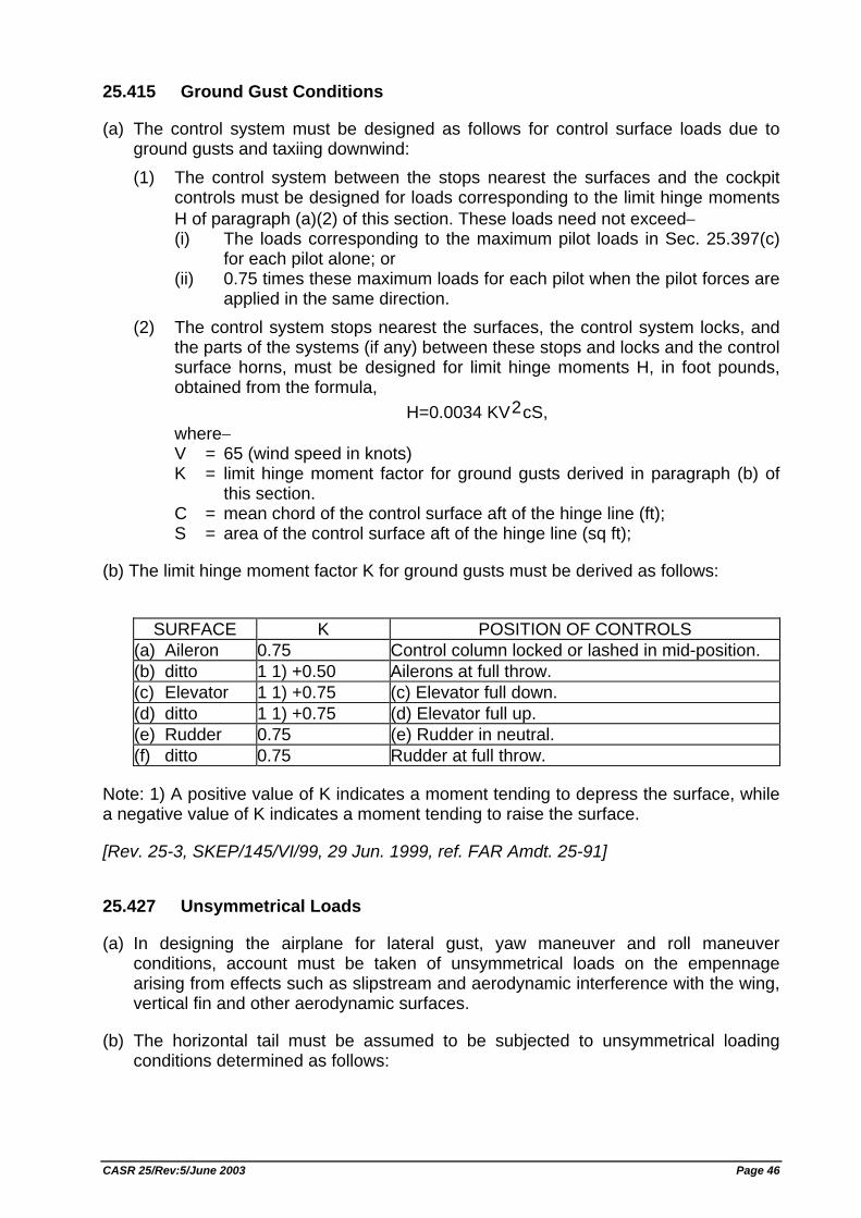
25.415 Ground Gust Conditions
(a) The control system must be designed as follows for control surface loads due to ground gusts and taxiing downwind: (1) The control system between the stops nearest the surfaces and the cockpit
controls must be designed for loads corresponding to the limit hinge moments H of paragraph (a)(2) of this section. These loads need not exceed− (i) The loads corresponding to the maximum pilot loads in Sec. 25.397(c)
for each pilot alone; or (ii) 0.75 times these maximum loads for each pilot when the pilot forces are
applied in the same direction. (2) The control system stops nearest the surfaces, the control system locks, and
the parts of the systems (if any) between these stops and locks and the control surface horns, must be designed for limit hinge moments H, in foot pounds, obtained from the formula,
H=0.0034 KV2cS, where− V = 65 (wind speed in knots) K = limit hinge moment factor for ground gusts derived in paragraph (b) of
this section. C = mean chord of the control surface aft of the hinge line (ft); S = area of the control surface aft of the hinge line (sq ft);
(b) The limit hinge moment factor K for ground gusts must be derived as follows:
SURFACE K POSITION OF CONTROLS
(a) Aileron 0.75 Control column locked or lashed in mid-position. (b) ditto 1 1) +0.50 Ailerons at full throw. (c) Elevator 1 1) +0.75 (c) Elevator full down. (d) ditto 1 1) +0.75 (d) Elevator full up. (e) Rudder 0.75 (e) Rudder in neutral. (f) ditto 0.75 Rudder at full throw.
Note: 1) A positive value of K indicates a moment tending to depress the surface, while a negative value of K indicates a moment tending to raise the surface.
[Rev. 25-3, SKEP/145/VI/99, 29 Jun. 1999, ref. FAR Amdt. 25-91]
25.427 Unsymmetrical Loads
(a) In designing the airplane for lateral gust, yaw maneuver and roll maneuver conditions, account must be taken of unsymmetrical loads on the empennage arising from effects such as slipstream and aerodynamic interference with the wing, vertical fin and other aerodynamic surfaces.
(b) The horizontal tail must be assumed to be subjected to unsymmetrical loading conditions determined as follows:
CASR 25/Rev:5/June 2003 Page 46
(1) 100 percent of the maximum loading from the symmetrical maneuver conditions of § 25.331 and the vertical gust conditions of § 25.341(a) acting separately on the surface on one side of the plane of symmetry; and
(2) 80 percent of these loadings acting on the other side.
(c) For empennage arrangements where the horizontal tail surfaces have dihedral angles greater than plus or minus 10 degrees, or are supported by the vertical tail surfaces, the surfaces and the supporting structure must be designed for gust velocities specified in § 25.341(a) acting in any orientation at right angles to the flight path.
(d) Unsymmetrical loading on the empennage arising from buffet conditions of § 25.305(e) must be taken into account. [Rev. 25-2, SKEP/199/XII/96, 26 Dec. 1996, ref. FAR Amdt. 25-86]
25.445 Auxiliary Aerodynamic Surfaces
(a) When significant, the aerodynamic influence between auxiliary aerodynamic surfaces, such as outboard fins and winglets, and their supporting aerodynamic surfaces, must be taken into account for all loading conditions including pitch, roll, and yaw maneuvers, and gusts as specified in § 25.341(a) acting at any orientation at right angles to the flight path.
(b) To provide for unsymmetrical loading when outboard fins extend above and below the horizontal surface, the critical vertical surface loading (load per unit area) determined under Sec. 25.391 must also be applied as follows: (1) 100 percent to the area of the vertical surfaces above (or below) the horizontal
surface. (2) 80 percent to the area below (or above) the horizontal surface. [Rev. 25-2, SKEP/199/XII/96, 26 Dec. 1996, ref. FAR Amdt. 25-86]
25.457 Wing Flaps
Wing flaps, their operating mechanisms, and their supporting structures must be designed for critical loads occurring in the conditions prescribed in Sec. 25.345, accounting for the loads occurring during transition from one flap position and airspeed to another.
25.459 Special Devices
The loading for special devices using aerodynamic surfaces (such as slots, slats, and spoilers) must be determined from test data.
CASR 25/Rev:5/June 2003 Page 47
GROUND LOADS
25.471 General
(a) Loads and equilibrium. For limit ground loads− (1) Limit ground loads obtained under this subpart are considered to be external
forces applied to the airplane structure; and (2) In each specified ground load condition, the external loads must be placed in
equilibrium with the linear and angular inertia loads in a rational or conservative manner.
(b) Critical centers of gravity. The critical centers of gravity within the range for which certification is requested must be selected so that the maximum design loads are obtained in each landing gear element. Fore and aft, vertical, and lateral airplane centers of gravity must be considered. Lateral displacements of the c.g. from the airplane centerline which would result in main gear loads not greater than 103 percent of the critical design load for symmetrical loading conditions may be selected without considering the effects of these lateral c.g. displacements on the loading of the main gear elements, or on the airplane structure provided− (1) The lateral displacement of the c.g. results from random passenger or cargo
disposition within the fuselage or from random unsymmetrical fuel loading or fuel usage; and
(2) Appropriate loading instructions for random disposable loads are included under the provisions of Sec. 25.1583(c)(1) to ensure that the lateral displacement of the center of gravity is maintained within these limits.
(c) Landing gear dimension data. Figure 1 of Appendix A contains the basic landing gear dimension data.
25.473 Landing Load Conditions and Assumptions
(a) For the landing conditions specified in § 25.479 to § 25.485 the airplane is assumed to contact the ground− (1) In the attitudes defined in § 25.479 and § 25.481; (2) With a limit descent velocity of 10 fps at the design landing weight (the
maximum weight for landing conditions at maximum descent velocity); and (3) With a limit descent velocity of 6 fps at the design take-off weight (the
maximum weight for landing conditions at a reduced descent velocity). (4) The prescribed descent velocities may be modified if it is shown that the
airplane has design features that make it impossible to develop these velocities.
(b) Airplane lift, not exceeding airplane weight, may be assumed unless the presence of systems or procedures significantly affects the lift.
(c) The method of analysis of airplane and landing gear loads must take into account at least the following elements:
CASR 25/Rev:5/June 2003 Page 48
(1) Landing gear dynamic characteristics. (2) Spin-up and springback. (3) Rigid body response. (4) Structural dynamic response of the airframe, if significant.
(d) The limit inertia load factors corresponding to the required limit descent velocities must be validated by tests as defined in § 25.723(a).
(e) The coefficient of friction between the tires and the ground may be established by considering the effects of skidding velocity and tire pressure. However, this coefficient of friction need not be more than 0.8. [Rev. 25-3, SKEP/145/VI/99, 29 Jun. 1999, ref. FAR Amdt. 25-91]
25.477 Landing Gear Arrangement
Sections 25.479 through 25.485 apply to airplanes with conventional arrangements of main and nose gears, or main and tail gears, when normal operating techniques are used.
25.479 Level Landing Conditions
(a) In the level attitude, the airplane is assumed to contact the ground at forward velocity components, ranging from VL1 to 1.25 VL2 parallel to the ground under the conditions prescribed in § 25.473 with− (1) VL1 equal to VS0 (TAS) at the appropriate landing weight and in standard sea
level conditions; and (2) VL2 equal to VS0 (TAS) at the appropriate landing weight and altitudes in a hot
day temperature of 41 degrees F. above standard. (3) The effects of increased contact speed must be investigated if approval of
downwind landings exceeding 10 knots is requested.
(b) For the level landing attitude for airplanes with tail wheels, the conditions specified in this section must be investigated with the airplane horizontal reference line horizontal in accordance with Figure 2 of Appendix A of this part.
(c) For the level landing attitude for airplanes with nose wheels, shown in Figure 2 of Appendix A of this part, the conditions specified in this section must be investigated assuming the following attitudes: (1) An attitude in which the main wheels are assumed to contact the ground with
the nose wheel just clear of the ground; and (2) If reasonably attainable at the specified descent and forward velocities, an
attitude in which the nose and main wheels are assumed to contact the ground simultaneously.
(d) In addition to the loading conditions prescribed in paragraph (a) of this section, but with maximum vertical ground reactions calculated from paragraph (a), the following apply:
CASR 25/Rev:5/June 2003 Page 49
(1) The landing gear and directly affected attaching structure must be designed for the maximum vertical ground reaction combined with an aft acting drag component of not less than 25% of this maximum vertical ground reaction.
(2) The most severe combination of loads that are likely to arise during a lateral drift landing must be taken into account. In absence of a more rational analysis of this condition, the following must be investigated: (i) A vertical load equal to 75% of the maximum ground reaction of §
25.473 must be considered in combination with a drag and side load of 40% and 25% respectively of that vertical load.
(ii) The shock absorber and tire deflections must be assumed to be 75% of the deflection corresponding to the maximum ground reaction of § 25.473(a)(2). This load case need not be considered in combination with flat tires.
(3) The combination of vertical and drag components is considered to be acting at the wheel axle centerline.
[Rev. 25-3, SKEP/145/VI/99, 29 Jun. 1999, ref. FAR Amdt. 25-91]
25.481 Tail Down Landing Conditions
(a) In the tail-down attitude, the airplane is assumed to contact the ground at forward velocity components, ranging from VL1 to VL2 parallel to the ground under the conditions prescribed in § 25.473 with - (1) VL1 equal to VS0 (TAS) at the appropriate landing weight and in standard sea
level conditions; and (2) VL2 equal to VS0 (TAS) at the appropriate landing weight and altitudes in a hot
day temperature of 41 degrees F. above standard. (3) The combination of vertical and drag components is considered to be acting at
the main wheel axle centerline.
(b) For the tail down landing condition for airplanes with tail wheels, the main and tail wheels are assumed to contact the ground simultaneously, in accordance with figure 3 of Appendix A. Ground reaction conditions on the tail wheel are assumed to act− (1) Vertically; and (2) Up and aft through the axle at 45 degrees to the ground line.
(c) For the tail down landing condition for airplanes with nose wheels, the airplane is assumed to be at an attitude corresponding to either the stalling angle or the maximum angle allowing clearance with the ground by each part of the airplane other than the main wheels, in accordance with figure 3 of Appendix A, whichever is less. [Rev. 25-3, SKEP/145/VI/99, 29 Jun. 1999, ref. FAR Amdt. 25-91]
25.483 One-gear Landing Conditions
For the one-gear landing conditions, the airplane is assumed to be in the level attitude and to contact the ground on one main landing gear, in accordance with Figure 4 of Appendix A of this part. In this attitude -
CASR 25/Rev:5/June 2003 Page 50
(a) The ground reactions must be the same as those obtained on that side under § 25.479(d)(1), and
(b) Each unbalanced external load must be reacted by airplane inertia in a rational or conservative manner. [Rev. 25-3, SKEP/145/VI/99, 29 Jun. 1999, ref. FAR Amdt. 25-91]
25.485 Side Load Conditions
In addition to § 25.479(d)(2) the following conditions must be considered:
(a) For the side load condition, the airplane is assumed to be in the level attitude with only the main wheels contacting the ground, in accordance with figure 5 of Appendix A.
(b) Side loads of 0.8 of the vertical reaction (on one side) acting inward and 0.6 of the vertical reaction (on the other side) acting outward must be combined with one-half of the maximum vertical ground reactions obtained in the level landing conditions. These loads are assumed to be applied at the ground contact point and to be resisted by the inertia of the airplane. The drag loads may be assumed to be zero. [Rev. 25-3, SKEP/145/VI/99, 29 Jun. 1999, ref. FAR Amdt. 25-91]
25.487 Rebound Landing Condition
(a) The landing gear and its supporting structure must be investigated for the loads occurring during rebound of the airplane from the landing surface.
(b) With the landing gear fully extended and not in contact with the ground, a load factor of 20.0 must act on the unsprung weights of the landing gear. This load factor must act in the direction of motion of the unsprung weights as they reach their limiting positions in extending with relation to the sprung parts of the landing gear.
25.489 Ground Handling Conditions
Unless otherwise prescribed, the landing gear and airplane structure must be investigated for the conditions in Secs. 25.491 through 25.509 with the airplane at the design ramp weight (the maximum weight for ground handling conditions). No wing lift may be considered. The shock absorbers and tires may be assumed to be in their static position.
25.491 Taxi, Takeoff and Landing Roll
Within the range of appropriate ground speeds and approved weights, the airplane structure and landing gear are assumed to be subjected to loads not less than those obtained when the aircraft is operating over the roughest ground that may reasonably be expected in normal operation.
[Rev. 25-3, SKEP/145/VI/99, 29 Jun. 1999, ref. FAR Amdt. 25-91]
CASR 25/Rev:5/June 2003 Page 51
25.493 Braked Roll Conditions
(a) An airplane with a tail wheel is assumed to be in the level attitude with the load on the main wheels, in accordance with figure 6 of Appendix A. The limit vertical load factor is 1.2 at the design landing weight and 1.0 at the design ramp weight. A drag reaction equal to the vertical reaction multiplied by a coefficient of friction of 0.8, must be combined with the vertical ground reaction and applied at the ground contact point.
(b) For an airplane with a nose wheel the limit vertical load factor is 1.2 at the design landing weight, and 1.0 at the design ramp weight. A drag reaction equal to the vertical reaction, multiplied by a coefficient of friction of 0.8, must be combined with the vertical reaction and applied at the ground contact point of each wheel with brakes. The following two attitudes, in accordance with figure 6 of Appendix A, must be considered: (1) The level attitude with the wheels contacting the ground and the loads
distributed between the main and nose gear. Zero pitching acceleration is assumed.
(2) The level attitude with only the main gear contacting the ground and with the pitching moment resisted by angular acceleration.
(c) A drag reaction lower than that prescribed in paragraphs (a) and (b) of this section may be used if it is substantiated that an effective drag force of 0.8 times the vertical reaction cannot be attained under any likely loading condition.
25.495 Turning
In the static position, in accordance with figure 7 of Appendix A, the airplane is assumed to execute a steady turn by nose gear steering, or by application of sufficient differential power, so that the limit load factors applied at the center of gravity are 1.0 vertically and 0.5 laterally. The side ground reaction of each wheel must be 0.5 of the vertical reaction.
25.497 Tail Wheel Yawing
(a) A vertical ground reaction equal to the static load on the tail wheel, in combination with a side component of equal magnitude, is assumed.
(b) If there is a swivel, the tail wheel is assumed to be swiveled 900 to the airplane longitudinal axis with the resultant load passing through the axle.
(c) If there is a lock, steering device, or shimmy damper the tail wheel is also assumed to be in the trailing position with the side load acting at the ground contact point.
25.499 Nose-wheel Yaw and Steering
(a) A vertical load factor of 1.0 at the airplane center of gravity, and a side component at the nose wheel ground contact equal to 0.8 of the vertical ground reaction at that point are assumed.
CASR 25/Rev:5/June 2003 Page 52
(b) With the airplane assumed to be in static equilibrium with the loads resulting from the use of brakes on one side of the main landing gear, the nose gear, its attaching structure, and the fuselage structure forward of the center of gravity must be designed for the following loads: (1) A vertical load factor at the center of gravity of 1.0. (2) A forward acting load at the airplane center of gravity of 0.8 times the vertical
load on one main gear. (3) Side and vertical loads at the ground contact point on the nose gear that are
required for static equilibrium. (4) A side load factor at the airplane center of gravity of zero.
(c) If the loads prescribed in paragraph (b) of this section result in a nose gear side load higher than 0.8 times the vertical nose gear load, the design nose gear side load may be limited to 0.8 times the vertical load, with unbalanced yawing moments assumed to be resisted by airplane inertia forces.
(d) For other than the nose gear, its attaching structure, and the forward fuselage structure, the loading conditions are those prescribed in paragraph (b) of this section, except that - (1) A lower drag reaction may be used if an effective drag force of 0.8 times the
vertical reaction cannot be reached under any likely loading condition; and (2) The forward acting load at the center of gravity need not exceed the maximum
drag reaction on one main gear, determined in accordance with Sec. 25.493(b).
(e) With the airplane at design ramp weight, and the nose gear in any steerable position, the combined application of full normal steering torque and vertical force equal to 1.33 times the maximum static reaction on the nose gear must be considered in designing the nose gear, its attaching structure, and the forward fuselage structure. [Rev. 25-3, SKEP/145/VI/99, 29 Jun. 1999, ref. FAR Amdt. 25-91]
25.503 Pivoting
(a) The airplane is assumed to pivot about one side of the main gear with the brakes on that side locked. The limit vertical load factor must be 1.0 and the coefficient of friction 0.8.
(b) The airplane is assumed to be in static equilibrium, with the loads being applied at the ground contact points, in accordance with figure 8 of Appendix A.
25.507 Reversed Braking
(a) The airplane must be in a three point static ground attitude. Horizontal reactions parallel to the ground and directed forward must be applied at the ground contact point of each wheel with brakes. The limit loads must be equal to 0.55 times the vertical load at each wheel or to the load developed by 1.2 times the nominal maximum static brake torque, whichever is less.
CASR 25/Rev:5/June 2003 Page 53
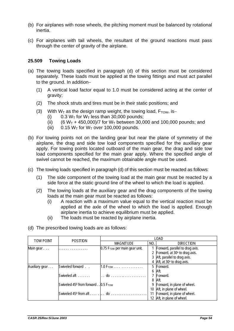
(b) For airplanes with nose wheels, the pitching moment must be balanced by rotational inertia.
(c) For airplanes with tail wheels, the resultant of the ground reactions must pass through the center of gravity of the airplane.
25.509 Towing Loads
(a) The towing loads specified in paragraph (d) of this section must be considered separately. These loads must be applied at the towing fittings and must act parallel to the ground. In addition− (1) A vertical load factor equal to 1.0 must be considered acting at the center of
gravity; (2) The shock struts and tires must be in their static positions; and
(3) With WT as the design ramp weight, the towing load, FTOW, is− (i) 0.3 WT for WT less than 30,000 pounds; (ii) (6 WT + 450,000)/7 for WT between 30,000 and 100,000 pounds; and (iii) 0.15 WT for WT over 100,000 pounds.
(b) For towing points not on the landing gear but near the plane of symmetry of the airplane, the drag and side tow load components specified for the auxiliary gear apply. For towing points located outboard of the main gear, the drag and side tow load components specified for the main gear apply. Where the specified angle of swivel cannot be reached, the maximum obtainable angle must be used.
(c) The towing loads specified in paragraph (d) of this section must be reacted as follows: (1) The side component of the towing load at the main gear must be reacted by a
side force at the static ground line of the wheel to which the load is applied. (2) The towing loads at the auxiliary gear and the drag components of the towing
loads at the main gear must be reacted as follows: (i) A reaction with a maximum value equal to the vertical reaction must be
applied at the axle of the wheel to which the load is applied. Enough airplane inertia to achieve equilibrium must be applied.
(ii) The loads must be reacted by airplane inertia.
(d) The prescribed towing loads are as follows:
LOAD TOW POINT POSITION MAGNITUDE NO. DIRECTION Main gear . . . . . . . . . . . . . . . . . . . 0.75 FTOW per main gear unit. 1
2 3 4
Forward, parallel to drag axis. Forward, at 30o to drag axis. Aft, parallel to drag axis. Aft, at 30o to drag axis.
Auxiliary gear . . . Swiveled forward . . Swiveled aft . . . . . . . Swiveled 450 from forward . . Swiveled 450 from aft . . . . .
1.0 FTOW . . . . . . . . . . . . . . . . . . do . . . . . . .. . . . . . . . . . . . . 0.5 FTOW .. . do . . . . . . . . . . . . . . . . . . . .
5 6 7 8 9
10 11 12
Forward. Aft. Forward. Aft. Forward, in plane of wheel. Aft, in plane of wheel. Forward, in plane of wheel. Aft, in plane of wheel.
CASR 25/Rev:5/June 2003 Page 54
25.511 Ground Load: Unsymmetrical Loads on Multiple Wheel Units
(a) General. Multiple wheel landing gear units are assumed to be subjected to the limit ground loads prescribed in this subpart under paragraphs (b) through (f) of this section. In addition− (1) A tandem strut gear arrangement is a multiple wheel unit; and (2) In determining the total load on a gear unit with respect to the provisions of
paragraphs (b) through (f) of this section, the transverse shift in the load centroid, due to unsymmetrical load distribution on the wheels, may be neglected.
(b) Distribution of limit loads to wheels; tires inflated. The distribution of the limit loads among the wheels of the landing gear must be established for each landing, taxiing, and ground handling condition, taking into account the effects of the following factors: (1) The number of wheels and their physical arrangements. For truck type landing
gear units, the effects of any seesaw motion of the truck during the landing impact must be considered in determining the maximum design loads for the fore and aft wheel pairs.
(2) Any differentials in tire diameters resulting from a combination of manufacturing tolerances, tire growth, and tire wear. A maximum tire diameter differential equal to 2/3 of the most unfavorable combination of diameter variations that is obtained when taking into account manufacturing tolerances, tire growth, and tire wear, may be assumed.
(3) Any unequal tire inflation pressure, assuming the maximum variation to be +5 percent of the nominal tire inflation pressure.
(4) A runway crown of zero and a runway crown having a convex upward shape that may be approximated by a slope of 1.5 percent with the horizontal. Runway crown effects must be considered with the nose gear unit on either slope of the crown.
(5) The airplane attitude. (6) Any structural deflections.
(c) Deflated tires. The effect of deflated tires on the structure must be considered with respect to the loading conditions specified in paragraphs (d) through (f) of this section, taking into account the physical arrangement of the gear components. In addition - (1) The deflation of any on e tire for each multiple wheel landing gear unit, and the
deflation of any two critical tires for each landing gear unit using four or more wheels per unit, must be considered; and
(2) The ground reactions must be applied to the wheels with inflated tires except that, for multiple wheel gear units with more than one shock strut, a rational distribution of the ground reactions between the deflated and inflated tires, accounting for the differences in shock strut extensions resulting from a deflated tire, may be used.
(d) Landing conditions. For one and for two deflated tires, the applied load to each gear unit is assumed to be 60 percent and 50 percent, respectively, of the limit load
CASR 25/Rev:5/June 2003 Page 55
applied to each gear for each of the prescribed landing conditions. However, for the drift landing condition of Sec. 25.485, 100 percent of the vertical load must be applied.
(e) Taxiing and ground handling conditions. For one and for two deflated tires− (1) The applied side or drag load factor, or both factors, at the center of gravity
must be the most critical value up to 50 percent and 40 percent, respectively, of the limit side or drag load factors, or both factors, corresponding to the most severe condition resulting from consideration of the prescribed taxiing and ground handling conditions;
(2) For the braked roll conditions of Sec. 25.493(a) and (b)(2), the drag loads on each inflated tire may not be less than those at each tire for the symmetrical load distribution with no deflated tires;
(3) The vertical load factor at the center of gravity must be 60 percent and 50 percent, respectively, of the factor with no deflated tires, except that it may not be less than 1 g; and
(4) Pivoting need not be considered.
(f) Towing conditions. For one and for two deflated tires, the towing load, Ftow, must be 60 percent and 50 percent, respectively, of the load prescribed.
25.519 Jacking and Tie-down Provisions
(a) General. The airplane must be designed to withstand the limit load conditions resulting from the static ground load conditions of paragraph (b) of this section and, if applicable, paragraph (c) of this section at the most critical combinations of airplane weight and center of gravity. The maximum allowable load at each jack pad must be specified.
(b) Jacking. The airplane must have provisions for jacking and must withstand the following limit loads when the airplane is supported on jacks− (1) For jacking by the landing gear at the maximum ramp weight of the airplane, the
airplane structure must be designed for a vertical load of 1.33 times the vertical static reaction at each jacking point acting singly and in combination with a horizontal load of 0.33 times the vertical static reaction applied in any direction.
(2) For jacking by other airplane structure at maximum approved jacking weight: (i) The airplane structure must be designed for a vertical load of 1.33 times
the vertical reaction at each jacking point acting singly and in combination with a horizontal load of 0.33 times the vertical static reaction applied in any direction.
(ii) The jacking pads and local structure must be designed for a vertical load of 2.0 times the vertical static reaction at each jacking point, acting singly and in combination with a horizontal load of 0.33 times the vertical static reaction applied in any direction.
(c) Tie-down. If tie-down points are provided, the main tie-down points and local structure must withstand the limit loads resulting from a 65 knot horizontal wind from any direction. [Rev. 25-1, KM.7 Year 1996, 15 Feb. 1996; ref. FAR Amdt. 25-77]
CASR 25/Rev:5/June 2003 Page 56
WATER LOADS
25.521 General
(a) Seaplanes must be designed for the water loads developed during takeoff and landing, with the seaplane in any attitude likely to occur in normal operation, and at the appropriate forward and sinking velocities under the most severe sea conditions likely to be encountered.
(b) Unless a more rational analysis of the water loads is made, or the standards in ANC-3 are used, Secs. 25.523 through 25.537 apply.
(c) The requirements of this section and Secs. 25.523 through 25.537 apply also to amphibians.
25.523 Design Weights and Center of Gravity Positions
(a) Design weights. The water load requirements must be met at each operating weight up to the design landing weight except that, for the takeoff condition prescribed in Sec. 25.531, the design water takeoff weight (the maximum weight for water taxi and takeoff run) must be used.
(b) Center of gravity positions. The critical centers of gravity within the limits for which certification is requested must be considered to reach maximum design loads for each part of the seaplane structure.
25.525 Application of Loads
(a) Unless otherwise prescribed, the seaplane as a whole is assumed to be subjected to the loads corresponding to the load factors specified in Sec. 25.527.
(b) In applying the loads resulting from the load factors prescribed in Sec. 25.527, the loads may be distributed over the hull or main float bottom (in order to avoid excessive local shear loads and bending moments at the location of water load application) using pressures not less than those prescribed in Sec. 25.533(b).
(c) For twin float seaplanes, each float must be treated as an equivalent hull on a fictitious seaplane with a weight equal to one-half the weight of the twin float seaplane.
(d) Except in the takeoff condition of Sec. 25.531, the aerodynamic lift on the seaplane during the impact is assumed to be 2/3 of the weight of the seaplane.
25.527 Hull and Main Float Load Factors
(a) Water reaction load factors nw must be computed in the following manner:
(1) For the step landing case nw = (C1.Vso2)/((tan2/3β)W1/3)
CASR 25/Rev:5/June 2003 Page 57
(2) For the bow and stern landing cases nw = [(C1.Vso2)/((tan2/3β)W1/3)] x [K1/(1 + rx2)2/3]
(b) The following values are used: (1) nw = water reaction load factor (that is, the water reaction divided by seaplane
weight). (2) C1 = empirical seaplane operations factor equal to 0.012 (except that this
factor may not be less than that necessary to obtain the minimum value of step load factor of 2.33).
(3) VS0 = seaplane stalling speed in knots with flaps extended in the appropriate landing position and with no slipstream effect.
(4) β = angle of dead rise at the longitudinal station at which the load factor is being determined in accordance with figure 1 of Appendix B.
(5) W = seaplane design landing weight in pounds. (6) K1 = empirical hull station weighing factor, in accordance with figure 2 of
Appendix B. (7) rx = ratio of distance, measured parallel to hull reference axis, from the center
of gravity of the seaplane to the hull longitudinal station at which the load factor is being computed to the radius of gyration in pitch of the seaplane, the hull reference axis being a straight line, in the plane of symmetry, tangential to the keel at the main step.
(c) For a twin float seaplane, because of the effect of flexibility of the attachment of the floats to the seaplane, the factor K1 may be reduced at the bow and stern to 0.8 of the value shown in figure 2 of Appendix B. This reduction applies only to the design of the carry through and seaplane structure.
25.529 Hull and Main Float Landing Conditions
(a) Symmetrical step, bow, and stern landing. For symmetrical step, bow, and stern landings, the limit water reaction load factors are those computed under Sec. 25.527. In addition− (1) For symmetrical step landings, the resultant water load must be applied at the
keel, through the center of gravity, and must be directed perpendicularly to the keel line;
(2) For symmetrical bow landings, the resultant water load must be applied at the keel, one-fifth of the longitudinal distance from the bow to the step, and must be directed perpendicularly to the keel line; and
(3) For symmetrical stern landings, the resultant water load must be applied at the keel, at a point 85 percent of the longitudinal distance from the step to the stern post, and must be directed perpendicularly to the keel line.
(b) Unsymmetrical landing for hull and single float seaplanes. Unsymmetrical step, bow, and stern landing conditions must be investigated. In addition− (1) The loading for each condition consists of an upward component and a side
component equal, respectively, to 0.75 and 0.25 tan β times the resultant load in the corresponding symmetrical landing condition; and
CASR 25/Rev:5/June 2003 Page 58
(2) The point of application and direction of the upward component of the load is the same as that in the symmetrical condition, and the point of application of the side component is at the same longitudinal station as the upward component but is directed inward perpendicularly to the plane of symmetry at a point midway between the keel and chine lines.
(c) Unsymmetrical landing; twin float seaplanes. The unsymmetrical loading consists of an upward load at the step of each float of 0.75 and a side load of 0.25 tan β at one float times the step landing load reached under Sec. 25.527. The side load is directed inboard, perpendicularly to the plane of symmetry midway between the keel and chine lines of the float, at the same longitudinal station as the upward load.
25.531 Hull and Main Float Takeoff Condition
For the wing and its attachment to the hull or main float−
(a) The aerodynamic wing lift is assumed to be zero; and
(b) A downward inertia load, corresponding to a load factor computed from the following formula, must be applied:
n = (CTO.Vs12)/(tan2/3β)W1/3
where− n = inertia load factor; CTO = empirical seaplane operations factor equal to 0.004;
VS1 = seaplane stalling speed (knots) at the design takeoff weight with the flaps extended in the appropriate takeoff position;
ß = angle of dead rise at the main step (degrees); and W = design water takeoff weight in pounds.
25.533 Hull and Main Float Bottom Pressures
(a) General. The hull and main float structure, including frames and bulkheads, stringers, and bottom plating, must be designed under this section.
(b) Local pressures. For the design of the bottom plating and stringers and their attachments to the supporting structure, the following pressure distributions must be applied: (1) For an unflared bottom, the pressure at the chine is 0.75 times the pressure at
the keel, and the pressures between the keel and chine vary linearly, in accordance with figure 3 of Appendix B. The pressure at the keel (psi) is computed as follows:
Pk = C2.(K2.Vs12)/(tan βk) where− Pk = pressure (p.s.i.) at the keel; C2 = 0.00213; K2 = hull station weighing factor, in accordance with figure 2 of Appendix B;
CASR 25/Rev:5/June 2003 Page 59
VS1 = seaplane stalling speed (Knots) at the design water takeoff weight with flaps extended in the appropriate takeoff position; and
βk = angle of dead rise at keel, in accordance with figure 1 of Appendix B.
(2) For a flared bottom, the pressure at the beginning of the flare is the same as that for an unflared bottom, and the pressure between the chine and the beginning of the flare varies linearly, in accordance with figure 3 of Appendix B. The pressure distribution is the same as that prescribed in paragraph (b)(1) of this section for an unflared bottom except that the pressure at the chine is computed as follows:
Pch = C3.(K2.Vs12)/(tan β) where− Pch = pressure (p.s.i.) at the chine; C3 = 0.0016; K2 = hull station weighing factor, in accordance with figure 2 of Appendix
B; VS1 = seaplane stalling speed at the design water takeoff weight with flaps
extended in the appropriate takeoff position; and β = angle of dead rise at appropriate station.
The area over which these pressures are applied must simulate pressures occurring during high localized impacts on the hull or float, but need not extend over an area that would induce critical stresses in the frames or in the overall structure.
(c) Distributed pressures. For the design of the frames, keel, and chine structure, the following pressure distributions apply: (1) Symmetrical pressures are computed as follows:
P = C4.(K2.VS02)/(tan β) where− P = pressure (p.s.i.); C4 = 0.078 C1 (with C1 computed under Sec. 25.527); K2 = hull station weighing factor, determined in accordance with figure 2 of
Appendix B; VS0 = seaplane stalling speed (Knots) with landing flaps extended in the
appropriate position and with no slipstream effect; and VS0 = seaplane stalling speed with landing flaps extended in the
appropriate position and with no slipstream effect; and β = angle of dead rise at appropriate station.
(2) The unsymmetrical pressure distribution consists of the pressures prescribed in paragraph (c)(1) of this section on one side of the hull or main float centerline and one-half of that pressure on the other side of the hull or main float centerline, in accordance with figure 3 of Appendix B.
These pressures are uniform and must be applied simultaneously over the entire hull or main float bottom. The loads obtained must be carried into the sidewall structure of the hull proper, but need not be transmitted in a fore and aft direction as shear and bending loads.
CASR 25/Rev:5/June 2003 Page 60
25.535 Auxiliary Float Loads
(a) General. Auxiliary floats and their attachments and supporting structures must be designed for the conditions prescribed in this section. In the cases specified in paragraphs (b) through (e) of this section, the prescribed water loads may be distributed over the float bottom to avoid excessive local loads, using bottom pressures not less than those prescribed in paragraph (g) of this section.
(b) Step loading. The resultant water load must be applied in the plane of symmetry of the float at a point three-fourths of the distance from the bow to the step and must be perpendicular to the keel. The resultant limit load is computed as follows, except that the value of L need not exceed three times the weight of the displaced water when the float is completely submerged:
L = (C5.VSo2.W2/3)/[tan2/3βs.(1 + ry2)2/3]
where− L = limit load (lbs.); C5 = 0.0053;
VS0 = seaplane stalling speed (knots) with landing flaps extended in the appropriate position and with no slipstream effect;
W = seaplane design landing weight in pounds;
βs = angle of dead rise at a station 3/4 of the distance from the bow to the step, but need not be less than 15 degrees; and
ry = ratio of the lateral distance between the center of gravity and the plane of symmetry of the float to the radius of gyration in roll.
(c) Bow loading. The resultant limit load must be applied in the plane of symmetry of the float at a point one-fourth of the distance from the bow to the step and must be perpendicular to the tangent to the keel line at that point. The magnitude of the resultant load is that specified in paragraph (b) of this section.
(d) Unsymmetrical step loading. The resultant water load consists of a component equal to 0.75 times the load specified in paragraph (a) of this section and a side component equal to 3.25 tan β times the load specified in paragraph (b) of this section. The side load must be applied perpendicularly to the plane of symmetry of the float at a point midway between the keel and the chine.
(e) Unsymmetrical bow loading. The resultant water load consists of a component equal to 0.75 times the load specified in paragraph (b) of this section and a side component equal to 0.25 tan β times the load specified in paragraph (c) of this section. The side load must be applied perpendicularly to the plane of symmetry at a point midway between the keel and the chine.
(f) Immersed float condition. The resultant load must be applied at the centroid of the cross section of the float at a point one-third of the distance from the bow to the step. The limit load components are as follows:
vertical = ρgV
aft = Cx2ρ V(2/3).(K.VSo)2
CASR 25/Rev:5/June 2003 Page 61
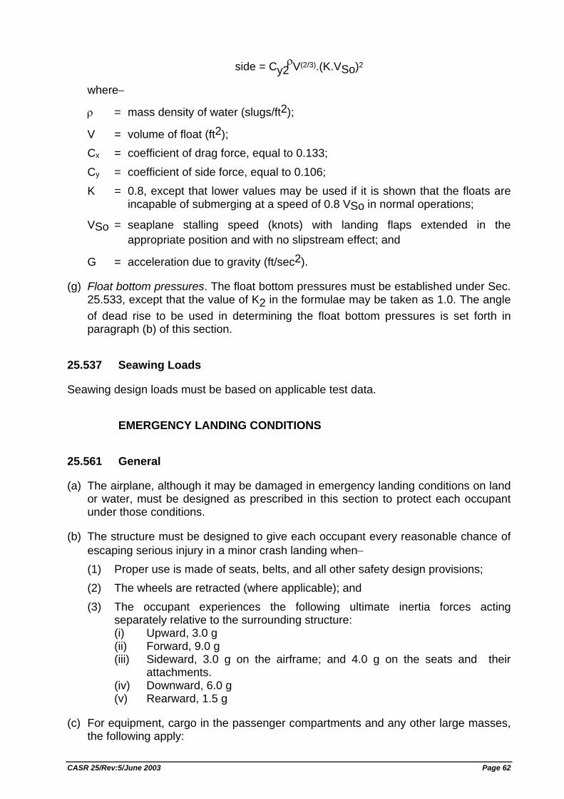
side = Cy2ρ V(2/3).(K.VSo)2
where−
ρ = mass density of water (slugs/ft2);
V = volume of float (ft2); Cx = coefficient of drag force, equal to 0.133;
Cy = coefficient of side force, equal to 0.106; K = 0.8, except that lower values may be used if it is shown that the floats are
incapable of submerging at a speed of 0.8 VSo in normal operations;
VSo = seaplane stalling speed (knots) with landing flaps extended in the appropriate position and with no slipstream effect; and
G = acceleration due to gravity (ft/sec2).
(g) Float bottom pressures. The float bottom pressures must be established under Sec. 25.533, except that the value of K2 in the formulae may be taken as 1.0. The angle of dead rise to be used in determining the float bottom pressures is set forth in paragraph (b) of this section.
25.537 Seawing Loads
Seawing design loads must be based on applicable test data.
EMERGENCY LANDING CONDITIONS
25.561 General
(a) The airplane, although it may be damaged in emergency landing conditions on land or water, must be designed as prescribed in this section to protect each occupant under those conditions.
(b) The structure must be designed to give each occupant every reasonable chance of escaping serious injury in a minor crash landing when− (1) Proper use is made of seats, belts, and all other safety design provisions; (2) The wheels are retracted (where applicable); and (3) The occupant experiences the following ultimate inertia forces acting
separately relative to the surrounding structure: (i) Upward, 3.0 g (ii) Forward, 9.0 g (iii) Sideward, 3.0 g on the airframe; and 4.0 g on the seats and their
attachments. (iv) Downward, 6.0 g (v) Rearward, 1.5 g
(c) For equipment, cargo in the passenger compartments and any other large masses, the following apply:
CASR 25/Rev:5/June 2003 Page 62
(1) Except as provided in paragraph (c)(2) of this section, these items must be positioned so that if they break loose they will be unlikely to: (i) Cause direct injury to occupants; (ii) Penetrate fuel tanks or lines or cause fire or explosion hazard by
damage to adjacent systems; or (iii) Nullify any of the escape facilities provided for use after an emergency
landing. (2) When such positioning is not practical (e.g. fuselage mounted engines or
auxiliary power units) each such item of mass shall be restrained under all loads up to those specified in paragraph (b)(3) of this section. The local attachments for these items should be designed to withstand 1.33 times the specified loads if these items are subject to severe wear and tear through frequent removal (e.g. quick change interior items).
(d) Seats and items of mass (and their supporting structure) must not deform under any loads up to those specified in paragraph (b)(3) of this section in any manner that would impede subsequent rapid evacuation of occupants. [Rev. 25-3, SKEP/145/VI/99, 29 Jun. 1999, ref. FAR Amdt. 25-91]
25.562 Emergency Landing Dynamic Conditions
(a) The seat and restraint system in the airplane must be designed as prescribed in this section to protect each occupant during an emergency landing condition when− (1) Proper use is made of seats, safety belts, and shoulder harnesses provided
for in the design; and (2) The occupant is exposed to loads resulting from the conditions prescribed in
this section.
(b) Each seat type design approved for crew or passenger occupancy during takeoff and landing must successfully complete dynamic tests or be demonstrated by rational analysis based on dynamic tests of a similar type seat, in accordance with each of the following emergency landing conditions. The tests must be conducted with an occupant simulated by a 170 pound anthropomorphic test dummy, or its equivalent, sitting in the normal upright position.
(1) A change in downward vertical velocity (Δv)of not less than 35 feet per second, with the airplane's longitudinal axis canted downward 30 degrees with respect to the horizontal plane and with the wings level. Peak floor deceleration must occur in not more than 0.08 seconds after impact and must reach a minimum of 14 g.
(2) A change in forward longitudinal velocity (Δv) of not less than 44 feet per second, with the airplane's longitudinal axis horizontal and yawed 10 degrees either right or left, whichever would cause the greatest likelihood of the upper torso restraint system (where installed) moving off the occupant's shoulder, and with the wings level. Peak floor deceleration must occur in not more than 0.09 seconds after impact and must reach a minimum of 16 g. Where floor rails or floor fittings are used to attach the seating devices to the test fixture, the rails or fittings must be misaligned with respect to the adjacent set of rails or fittings by at least 10 degrees vertically (i.e., out of Parallel) with one rolled 10 degrees.
CASR 25/Rev:5/June 2003 Page 63
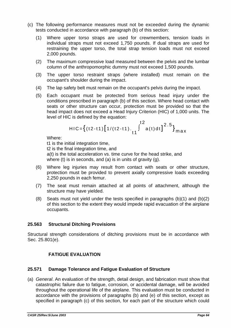
(c) The following performance measures must not be exceeded during the dynamic tests conducted in accordance with paragraph (b) of this section: (1) Where upper torso straps are used for crewmembers, tension loads in
individual straps must not exceed 1,750 pounds. If dual straps are used for restraining the upper torso, the total strap tension loads must not exceed 2,000 pounds.
(2) The maximum compressive load measured between the pelvis and the lumbar column of the anthropomorphic dummy must not exceed 1,500 pounds.
(3) The upper torso restraint straps (where installed) must remain on the occupant's shoulder during the impact.
(4) The lap safety belt must remain on the occupant's pelvis during the impact. (5) Each occupant must be protected from serious head injury under the
conditions prescribed in paragraph (b) of this section. Where head contact with seats or other structure can occur, protection must be provided so that the head impact does not exceed a Head Injury Criterion (HIC) of 1,000 units. The level of HIC is defined by the equation:
H I C = { ( t 2 - t 1 ) [ 1 / ( t 2 - t 1 ) .t 1∫t 2
a ( t ) d t ] 2 . 5 }m a x
Where: t1 is the initial integration time, t2 is the final integration time, and a(t) is the total acceleration vs. time curve for the head strike, and where (t) is in seconds, and (a) is in units of gravity (g).
(6) Where leg injuries may result from contact with seats or other structure, protection must be provided to prevent axially compressive loads exceeding 2,250 pounds in each femur.
(7) The seat must remain attached at all points of attachment, although the structure may have yielded.
(8) Seats must not yield under the tests specified in paragraphs (b)(1) and (b)(2) of this section to the extent they would impede rapid evacuation of the airplane occupants.
25.563 Structural Ditching Provisions
Structural strength considerations of ditching provisions must be in accordance with Sec. 25.801(e).
FATIGUE EVALUATION
25.571 Damage Tolerance and Fatigue Evaluation of Structure
(a) General. An evaluation of the strength, detail design, and fabrication must show that catastrophic failure due to fatigue, corrosion, or accidental damage, will be avoided throughout the operational life of the airplane. This evaluation must be conducted in accordance with the provisions of paragraphs (b) and (e) of this section, except as specified in paragraph (c) of this section, for each part of the structure which could
CASR 25/Rev:5/June 2003 Page 64
contribute to a catastrophic failure (such as wing, empennage, control surfaces and their systems, the fuselage, engine mounting, landing gear, and their related primary attachments). Advisory Circular AC No. 25.571-1 contains guidance information relating to the requirements of this section. For turbojet powered airplanes, those parts which could contribute to a catastrophic failure must also be evaluated under paragraph (d) of this section. In addition, the following apply:
(1) Each evaluation required by this section must include− (i) The typical loading spectra, temperatures and humidities expected in
service; (ii) The identification of principal structural elements and detail design
points, the failure of which could cause catastrophic failure of the airplane; and
(iii) An analysis, supported by test evidence, of the principal structural elements and detail design points identified in paragraph (a)(1)(ii) of this section.
(2) The service history of airplanes of similar structural design, taking due account of differences in operating conditions and procedures, may be used in the evaluations required by this section.
(3) Based on the evaluations required by this section, inspections or other procedures must be established as necessary to prevent catastrophic failure, and must be included in the Airworthiness Limitations section of the Instruction for Continued Airworthiness required by Sec. 25.1529.
(b) Damage tolerance evaluation. The evaluation must include a determination of the probable locations and modes of damage due to fatigue, corrosion, or accidental damage. The determination must be by analysis supported by test evidence and (if available) service experience. Damage at multiple sites due to prior fatigue exposure must be included where the design is such that this type of damage can be expected to occur. The evaluation must incorporate repeated load and static analyses supported by test evidence. The extent of damage for residual strength evaluation at any time within the operational life must be consistent with the initial detectability and subsequent growth under repeated loads. The residual strength evaluation must show that the remaining structure is able to withstand loads (considered as static ultimate loads) corresponding to the following conditions: (1) The limit symmetrical maneuvering conditions specified in Sec. 25.337 at VC
and in Sec. 25.345. (2) The limit gust conditions specified in § 25.341 at the specified speeds up to VC
and in § 25.345. (3) The limit rolling conditions specified in § 25.349 and the limit unsymmetrical
conditions specified in §§ 25.367 and 25.427 (a) through (c), at speeds up to VC.
(4) The limit yaw maneuvering conditions specified in Sec. 25.351(a) at the specified speeds up to VC.
(5) For pressurized cabins, the following conditions: (i) The normal operating differential pressure combined with the expected
external aerodynamic pressures applied simultaneously with the flight loading conditions specified in paragraphs (b) (1) through (4) of this section, if they have a significant effect.
CASR 25/Rev:5/June 2003 Page 65
(ii) The expected external aerodynamic pressures in 1 g flight combined with a cabin differential pressure equal to 1.1 times the normal operating differential pressure without any other load.
(6) For landing gear and directly affected airframe structure, the limit ground loading conditions specified in Secs. 25.473, 25.491, and 25.493.
If significant changes in structural stiffness or geometry, or both, follow from a structural failure, or partial failure, the effect on damage tolerance must be further investigated.
(c) Fatigue (safe life) evaluation. Compliance with the damage tolerance requirements of paragraph (b) of this section is not required if the applicant establishes that their application for particular structure is impractical. This structure must be shown by analysis, supported by test evidence, to be able to withstand the repeated loads of variable magnitude expected during its service life without detectable cracks. Appropriate safe life scatter factors must be applied.
(d) Sonic fatigue strength. It must be shown by analysis, supported by test evidence, or by the service history of airplanes of similar structural design and sonic excitation environment, that− (1) Sonic fatigue cracks are not probable in any part of the flight structure subject
to sonic excitation; or (2) Catastrophic failure caused by sonic cracks is not probable assuming that the
loads prescribed in paragraph (b) of this section are applied to all areas affected by those cracks.
(e) Damage tolerance (discrete source) evaluation. The airplane must be capable of successfully completing a flight during which likely structural damage occurs as a result of− (1) Impact with a 4 pound bird at Vc at sea level to 8,000 feet;
(2) Uncontained fan blade impact; (3) Uncontained engine failure; or (4) Uncontained high energy rotating machinery failure. The damaged structure must be able to withstand the static loads (considered as ultimate loads) which are reasonably expected to occur on the flight. Dynamic effects on these static loads need not be considered. Corrective action to be taken by the pilot following the incident, such as limiting maneuvers, avoiding turbulence, and reducing speed, must be considered. If significant changes in structural stiffness or geometry, or both, follow from a structural failure or partial failure, the effect on damage tolerance must be further investigated. [Rev. 25-2, SKEP/199/XII/96, 26 Dec. 1996, ref. FAR Amdt. 25-86]
LIGHTNING PROTECTION
25.581 Lightning Protection
(a) The airplane must be protected against catastrophic effects from lightning.
CASR 25/Rev:5/June 2003 Page 66
(b) For metallic components, compliance with paragraph (a) of this section may be shown by− (1) Bonding the components properly to the airframe; or (2) Designing the components so that a strike will not endanger the airplane.
(c) For nonmetallic components, compliance with paragraph (a) of this section may be shown by− (1) Designing the components to minimize the effect of a strike; or (2) Incorporating acceptable means of diverting the resulting electrical current so
as not to endanger the airplane.
CASR 25/Rev:5/June 2003 Page 67
SUBPART D - DESIGN AND CONSTRUCTION
GENERAL
25.601 General
The airplane may not have design features or details that experience has shown to be hazardous or unreliable. The suitability of each questionable design detail and part must be established by tests.
25.603 Materials
The suitability and durability of materials used for parts, the failure of which could adversely affect safety, must−
(a) Be established on the basis of experience or tests;
(b) Conform to approved specifications that ensure their having the strength and other properties assumed in the design data; and
(c) Take into account the effects of environmental conditions, such as temperature and humidity, expected in service.
25.605 Fabrication Methods
(a) The methods of fabrication used must produce a consistently sound structure. If a fabrication process (such as gluing, spot welding, or heat treating) requires close control to reach this objective, the process must be performed under an approved process specification.
(b) Each new aircraft fabrication method must be substantiated by a test program.
25.607 Fasteners
(a) Each removable bolt, screw, nut, pin, or other removable fastener must incorporate two separate locking devices if− (1) Its loss could preclude continued flight and landing within the design limitations
of the airplane using normal pilot skill and strength; or (2) Its loss could result in reduction in pitch, yaw, or roll control capability or
response below that required by Subpart B of this attachment.
(b) The fasteners specified in paragraph (a) of this section and their locking devices may not be adversely affected by the environmental conditions associated with the particular installation.
(c) No self-locking nut may be used on any bolt subject to rotation in operation unless a nonfriction locking device is used in addition to the self-locking device.
CASR 25/Rev:5/June 2003 Page 68
25.609 Protection of Structure
Each part of the structure must−
(a) Be suitably protected against deterioration or loss of strength in service due to any cause, including− (1) Weathering; (2) Corrosion; and (3) Abrasion; and
(b) Have provisions for ventilation and drainage where necessary for protection.
25.611 Accessibility Provisions
Means must be provided to allow inspection (including inspection of principal structural elements and control systems), replacement of parts normally requiring replacement, adjustment, and lubrication as necessary for continued airworthiness. The inspection means for each item must be practicable for the inspection interval for the item. Nondestructive inspection aids may be used to inspect structural elements where it is impracticable to provide means for direct visual inspection if it is shown that the inspection is effective and the inspection procedures are specified in the maintenance manual required by Sec. 25.1529.
25.613 Material Strength Properties and Design Values
(a) Material strength properties must be based on enough tests of material meeting approved specifications to establish design values on a statistical basis.
(b) Design values must be chosen to minimize the probability of structural failures due to material variability. Except as provided in paragraph (e) of this section, compliance with this paragraph must be shown by selecting design values which assure material strength with the following probability: (1) Where applied loads are eventually distributed through a single member within
an assembly, the failure of which would result in loss of structural integrity of the component, 99 percent probability with 95 percent confidence.
(2) For redundant structure, in which the failure of individual elements would result in applied loads being safely distributed to other load carrying members, 90 percent probability with 95 percent confidence.
(c) The effects of temperature on allowable stresses used for design in an essential component or structure must be considered where thermal effects are significant under normal operating conditions.
(d) The strength, detail design, and fabrication of the structure must minimize the probability of disastrous fatigue failure, particularly at points of stress concentration.
(e) Greater design values may be used if a "premium selection" of the material is made in which a specimen of each individual item is tested before use to determine that the actual strength properties of that particular item will equal or exceed those used in design.
CASR 25/Rev:5/June 2003 Page 69
25.619 Special Factors
The factor of safety prescribed in Sec. 25.303 must be multiplied by the highest pertinent special factor of safety prescribed in Secs. 25.621 through 25.625 for each part of the structure whose strength is−
(a) Uncertain;
(b) Likely to deteriorate in service before normal replacement; or
(c) Subject to appreciable variability because of uncertainties in manufacturing processes or inspection methods.
25.621 Casting Factors
(a) General. The factors, tests, and inspections specified in paragraphs (b) through (d) of this section must be applied in addition to those necessary to establish foundry quality control. The inspections must meet approved specifications. Paragraphs (c) and (d) of this section apply to any structural castings except castings that are pressure tested as parts of hydraulic or other fluid systems and do not support structural loads.
(b) Bearing stresses and surfaces. The casting factors specified in paragraphs (c) and (d) of this section− (1) Need not exceed 1.25 with respect to bearing stresses regardless of the
method of inspection used; and (2) Need not be used with respect to the bearing surfaces of a part whose bearing
factor is larger than the applicable casting factor.
(c) Critical castings. For each casting whose failure would preclude continued safe flight and landing of the airplane or result in serious injury to occupants, the following apply:
(1) Each critical casting must− (i) Have a casting factor of not less than 1.25; and (ii) Receive 100 percent inspection by visual, radiographic, and magnetic
particle or penetrant inspection methods or approved equivalent nonde-structive inspection methods.
(2) For each critical casting with a casting factor less than 1.50, three sample castings must be static tested and shown to meet− (i) The strength requirements of Sec. 25.305 at an ultimate load
corresponding to a casting factor of 1.25; and (ii) The deformation requirements of Sec. 25.305 at a load of 1.15 times the
limit load. (3) Examples of these castings are structural attachment fittings, parts of flight
control systems, control surface hinges and balance weight attachments, seat, berth, safety belt, and fuel and oil tank supports and attachments, and cabin pressure valves.
(d) Noncritical castings. For each casting other than those specified in paragraph (c) of this section, the following apply:
CASR 25/Rev:5/June 2003 Page 70
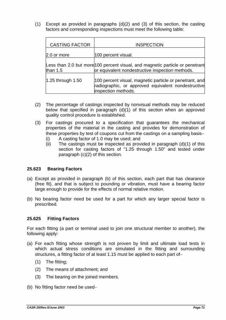
(1) Except as provided in paragraphs (d)(2) and (3) of this section, the casting factors and corresponding inspections must meet the following table:
CASTING FACTOR INSPECTION
2.0 or more 100 percent visual.
Less than 2.0 but morethan 1.5
100 percent visual, and magnetic particle or penetrant or equivalent nondestructive inspection methods.
1.25 through 1.50 100 percent visual, magnetic particle or penetrant, and radiographic, or approved equivalent nondestructive inspection methods.
(2) The percentage of castings inspected by nonvisual methods may be reduced below that specified in paragraph (d)(1) of this section when an approved quality control procedure is established.
(3) For castings procured to a specification that guarantees the mechanical properties of the material in the casting and provides for demonstration of these properties by test of coupons cut from the castings on a sampling basis− (i) A casting factor of 1.0 may be used; and (ii) The castings must be inspected as provided in paragraph (d)(1) of this
section for casting factors of "1.25 through 1.50" and tested under paragraph (c)(2) of this section.
25.623 Bearing Factors
(a) Except as provided in paragraph (b) of this section, each part that has clearance (free fit), and that is subject to pounding or vibration, must have a bearing factor large enough to provide for the effects of normal relative motion.
(b) No bearing factor need be used for a part for which any larger special factor is prescribed.
25.625 Fitting Factors
For each fitting (a part or terminal used to join one structural member to another), the following apply:
(a) For each fitting whose strength is not proven by limit and ultimate load tests in which actual stress conditions are simulated in the fitting and surrounding structures, a fitting factor of at least 1.15 must be applied to each part of− (1) The fitting; (2) The means of attachment; and (3) The bearing on the joined members.
(b) No fitting factor need be used−
CASR 25/Rev:5/June 2003 Page 71

(1) For joints made under approved practices and based on comprehensive test data (such as continuous joints in metal plating, welded joints, and scarf joints in wood); or
(2) With respect to any bearing surface for which a larger special factor is used.
(c) For each integral fitting, the part must be treated as a fitting up to the point at which the section properties become typical of the member.
(d) For each seat, berth, safety belt, and harness, the fitting factor specified in Sec. 25.785(f)(3) applies.
25.629 Aeroelastic Stability Requirements
(a) General. The aeroelastic stability evaluations required under this section include flutter, divergence, control reversal and any undue loss of stability and control as a result of structural deformation. The aeroelastic evaluation must include whirl modes associated with any propeller or rotating device that contributes significant dynamic forces. Compliance with this section must be shown by analyses, wind tunnel tests, ground vibration tests, flight tests, or other means found necessary by the Director General.
(b) Aeroelastic stability envelopes. The airplane must be designed to be free from aeroelastic instability for all configurations and design conditions within the aeroelastic stability envelopes as follows: (1) For normal conditions without failures, malfunctions, or adverse conditions, all
combinations of altitudes and speeds encompassed by the Vd/Md versus altitude envelope enlarged at all points by an increase of 15 percent in equivalent airspeed at both constant Mach number and constant altitude. In addition, a proper margin of stability must exist at all speeds up to Vd/Md and, there must be no large and rapid reduction in stability as Vd/Md is approached. The enlarged envelope may be limited to Mach 1.0 when Md is less than 1.0 at all design altitudes, and
(2) For the conditions described in Sec. 25.629(d) below, for all approved altitudes, any airspeed up to the greater airspeed defined by: (i) The Vd/Md envelope determined by Sec. 25.335(b); or, (ii) An altitude-airspeed envelope defined by a 15 percent increase in
equivalent airspeed above Vc at constant altitude, from sea level to the altitude of the intersection of 1.15 Vc with the extension of the constant cruise Mach number line, Mc, then a linear variation in equivalent airspeed to Mc +0.05 at the altitude of the lowest Vc/Mc intersection; then, at higher altitudes, up to the maximum flight altitude, the boundary defined by a 0.05 Mach increase in Mc at constant altitude.
(c) Balance weights. If concentrated balance weights are used, their effectiveness and strength, including supporting structure, must be substantiated.
(d) Failures, malfunctions and adverse conditions. The failures, malfunctions, and adverse conditions which must be considered in showing compliance with this section are: (1) Any critical fuel loading conditions, not shown to be extremely improbable,
which may result from mismanagement of fuel.
CASR 25/Rev:5/June 2003 Page 72
(2) Any single failure in any flutter damper system. (3) For airplanes not approved for operation in icing conditions, the maximum
likely ice accumulation expected as a result of an inadvertent encounter. (4) Failure of any single element of the structure supporting any engine,
independently mounted propeller shaft, large auxiliary power unit, or large externally mounted aerodynamic body (such as an external fuel tank).
(5) For airplanes with engines that have propellers or large rotating devices capable of significant dynamic forces, any single failure of the engine structure that would reduce the rigidity of the rotational axis.
(6) The absence of aerodynamic or gyroscopic forces resulting from the most adverse combination of feathered propellers or other rotating devices capable of significant dynamic forces. In addition, the effect of a single feathered propeller or rotating device must be coupled with the failures of paragraphs (d)(4) and (d)(5) of this section.
(7) Any single propeller or rotating device capable of significant dynamic forces rotating at the highest likely overspeed.
(8) Any damage or failure condition, required or selected for investigation by Sec. 25.571. The single structural failures described in paragraphs (d)(4) and (d)(5) of this section need not be considered in showing compliance with this section if; (i) The structural element could not fail due to discreet source damage
resulting from the conditions described in Sec. 25.571(e), and (ii) A damage tolerance investigation in accordance with Sec.25.571(b)
shows that the maximum extent of damage assumed for the purpose of residual strength evaluation does not involve complete failure of the structural element.
(9) Any damage, failure, or malfunction considered under Secs. 25.631, 25.671, 25.672, and 25.1309.
(10) Any other combination of failures, malfunctions, or adverse conditions not shown to be extremely improbable.
(e) Flight flutter testing. Full scale flight flutter tests at speeds up to Vdf/Mdf must be conducted for new type designs and for modifications to a type design unless the modifications have been shown to have an insignificant effect on the aeroelastic stability. These tests must demonstrate that the airplane has a proper margin of damping at all speeds up to Vdf/Mdf and that there is no large and rapid reduction in damping as Vdf/Mdf is approached. If a failure, malfunction, or adverse condition is simulated during flight test in showing compliance with paragraph (d) of this section, the maximum speed investigated need not exceed Vfc/Mfc if it is shown, by correlation of the flight test data with other test data or analyses, that the airplane is free from any aeroelastic instability at all speeds within the altitude-airspeed envelope described in paragraph (b)(2) of this section. [Rev. 25-1, KM. 7 Year 1996, 15 Feb. 1996, ref. FAR Amdt. 25-77]
25.631 Bird Strike Damage
The empennage structure must be designed to assure capability of continued safe flight and landing of the airplane after impact with an 8 pound bird when the velocity of the
CASR 25/Rev:5/June 2003 Page 73
airplane (relative to the bird along the airplane's flight path) is equal to Vc at sea level, selected under Sec. 25.335(a). Compliance with this section by provision of redundant structure and protected location of control system elements or protective devices such as splitter plates or energy absorbing material is acceptable. Where compliance is shown by analysis, tests, or both, use of data on airplanes having similar structural design is acceptable.
CONTROL SURFACES
25.651 Proof of Strength
(a) Limit load tests of control surfaces are required. These tests must include the horn or fitting to which the control system is attached.
(b) Compliance with the special factors requirements of Secs. 25.619 through 25.625 and 25.657 for control surface hinges must be shown by analysis or individual load tests.
25.655 Installation
(a) Movable tail surfaces must be installed so that there is no interference between any surfaces when one is held in its extreme position and the others are operated through their full angular movement.
(b) If an adjustable stabilizer is used, it must have stops that will limit its range of travel to the maximum for which the airplane is shown to meet the trim requirements of Sec. 25.161.
25.657 Hinges
(a) For control surface hinges, including ball, roller, and self-lubricated bearing hinges, the approved rating of the bearing may not be exceeded. For nonstandard bearing hinge configurations, the rating must be established on the basis of experience or tests and, in the absence of a rational investigation, a factor of safety of not less than 6.67 must be used with respect to the ultimate bearing strength of the softest material used as a bearing.
(b) Hinges must have enough strength and rigidity for loads parallel to the hinge line.
CONTROL SYSTEMS
25.671 General
(a) Each control and control system must operate with the ease, smoothness, and positiveness appropriate to its function.
(b) Each element of each flight control system must be designed, or distinctively and permanently marked, to minimize the probability of incorrect assembly that could result in the malfunctioning of the system.
CASR 25/Rev:5/June 2003 Page 74
(c) The airplane must be shown by analysis, tests, or both, to be capable of continued safe flight and landing after any of the following failures or jamming in the flight control system and surfaces (including trim, lift, drag, and feel systems), within the normal flight envelope, without requiring exceptional piloting skill or strength. Probable malfunctions must have only minor effects on control system operation and must be capable of being readily counteracted by the pilot. (1) Any single failure, excluding jamming (for example, disconnection or failure of
mechanical elements, or structural failure of hydraulic components, such as actuators, control spool housing, and valves).
(2) Any combination of failures not shown to be extremely improbable, excluding jamming (for example, dual electrical or hydraulic system failures, or any single failure in combination with any probable hydraulic or electrical failure).
(3) Any jam in a control position normally encountered during takeoff, climb, cruise, normal turns, descent, and landing unless the jam is shown to be extremely improbable, or can be alleviated. A runaway of a flight control to an adverse position and jam must be accounted for if such runaway and subsequent jamming is not extremely improbable.
(d) The airplane must be designed so that it is controllable if all engines fail. Compliance with this requirement may be shown by analysis where that method has been shown to be reliable.
25.672 Stability Augmentation and Automatic and Power Operated Systems
If the functioning of stability augmentation or other automatic or power operated systems is necessary to show compliance with the flight characteristics requirements of this attachment, such systems must comply with Sec. 25.671 and the following:
(a) A warning which is clearly distinguishable to the pilot under expected flight conditions without requiring his attention must be provided for any failure in the stability augmentation system or in any other automatic or power operated system which could result in an unsafe condition if the pilot were not aware of the failure. Warning systems must not activate the control systems.
(b) The design of the stability augmentation system or of any other automatic or power operated system must permit initial counteraction of failures of the type specified in Sec. 25.671(c) without requiring exceptional pilot skill or strength, by either the deactivation of the system, or a failed portion thereof, or by overriding the failure by movement of the flight controls in the normal sense.
(c) It must be shown that after any single failure of the stability augmentation system or any other automatic or power operated system− (1) The airplane is safely controllable when the failure or malfunction occurs at
any speed or altitude within the approved operating limitations that is critical for the type of failure being considered;
(2) The controllability and maneuverability requirements of this attachment are met within a practical operational flight envelope (for example, speed, altitude, normal acceleration, and airplane configurations) which is described in the Airplane Flight Manual; and
CASR 25/Rev:5/June 2003 Page 75
(3) The trim, stability, and stall characteristics are not impaired below a level needed to permit continued safe flight and landing.
25.675 Stops
(a) Each control system must have stops that positively limit the range of motion of each movable aerodynamic surface controlled by the system.
(b) Each stop must be located so that wear, slackness, or takeup adjustments will not adversely affect the control characteristics of the airplane because of a change in the range of surface travel.
(c) Each stop must be able to withstand any loads corresponding to the design conditions for the control system.
25.677 Trim Systems
(a) Trim controls must be designed to prevent inadvertent or abrupt operation and to operate in the plane, and with the sense of motion, of the airplane.
(b) There must be means adjacent to the trim control to indicate the direction of the control movement relative to the airplane motion. In addition, there must be clearly visible means to indicate the position of the trim device with respect to the range of adjustment.
(c) Trim control systems must be designed to prevent creeping in flight. Trim tab controls must be irreversible unless the tab is appropriately balanced and shown to be free from flutter.
(d) If an irreversible tab control system is used, the part from the tab to the attachment of the irreversible unit to the airplane structure must consist of a rigid connection.
25.679 Control System Gust Locks
(a) There must be a device to prevent damage to the control surfaces (including tabs), and to the control system, from gusts striking the airplane while it is on the ground or water. If the device, when engaged, prevents normal operation of the control surfaces by the pilot, it must− (1) Automatically disengage when the pilot operates the primary flight controls in a
normal manner; or (2) Limit the operation of the airplane so that the pilot receives unmistakable
warning at the start of takeoff.
(b) The device must have means to preclude the possibility of it becoming inadvertently engaged in flight.
25.681 Limit Load Static Tests
(a) Compliance with the limit load requirements of this attachment must be shown by tests in which−
CASR 25/Rev:5/June 2003 Page 76
(1) The direction of the test loads produces the most severe loading in the control system; and
(2) Each fitting, pulley, and bracket used in attaching the system to the main structure is included.
(b) Compliance must be shown (by analyses or individual load tests) with the special factor requirements for control system joints subject to angular motion.
25.683 Operation Tests
It must be shown by operation tests that when portions of the control system subject to pilot effort loads are loaded to 80 percent of the limit load specified for the system and the powered portions of the control system are loaded to the maximum load expected in normal operation, the system is free from−
(a) Jamming;
(b) Excessive friction; and
(c) Excessive deflection.
25.685 Control System Details
(a) Each detail of each control system must be designed and installed to prevent jamming, chafing, and interference from cargo, passengers, loose objects, or the freezing of moisture.
(b) There must be means in the cockpit to prevent the entry of foreign objects into places where they would jam the system.
(c) There must be means to prevent the slapping of cables or tubes against other parts.
(d) Sections 25.689 and 25.693 apply to cable systems and joints.
25.689 Cable Systems
(a) Each cable, cable fitting, turnbuckle, splice, and pulley must be approved. In addition− (1) No cable smaller than 1/8 inch in diameter may be used in the aileron,
elevator, or rudder systems; and (2) Each cable system must be designed so that there will be no hazardous
change in cable tension throughout the range of travel under operating conditions and temperature variations.
(b) Each kind and size of pulley must correspond to the cable with which it is used. Pulleys and sprockets must have closely fitted guards to prevent the cables and chains from being displaced or fouled. Each pulley must lie in the plane passing through the cable so that the cable does not rub against the pulley flange.
(c) Fairleads must be installed so that they do not cause a change in cable direction of more than three degrees.
CASR 25/Rev:5/June 2003 Page 77
(d) Clevis pins subject to load or motion and retained only by cotter pins may not be used in the control system.
(e) Turnbuckles must be attached to parts having angular motion in a manner that will positively prevent binding throughout the range of travel.
(f) There must be provisions for visual inspection of fairleads, pulleys, terminals, and turnbuckles.
25.693 Joints
Control system joints (in push-pull systems) that are subject to angular motion, except those in ball and roller bearing systems, must have a special factor of safety of not less than 3.33 with respect to the ultimate bearing strength of the softest material used as a bearing. This factor may be reduced to 2.0 for joints in cable control systems. For ball or roller bearings, the approved ratings may not be exceeded.
25.697 Lift and Drag Devices, Controls
(a) Each lift device control must be designed so that the pilots can place the device in any takeoff, enroute, approach, or landing position established under Sec. 25.101(d). Lift and drag devices must maintain the selected positions, except for movement produced by an automatic positioning or load limiting device, without further attention by the pilots.
(b) Each lift and drag device control must be designed and located to make inadvertent operation improbable. Lift and drag devices intended for ground operation only must have means to prevent the inadvertent operation of their controls in flight if that operation could be hazardous.
(c) The rate of motion of the surfaces in response to the operation of the control and the characteristics of the automatic positioning or load limiting device must give satisfactory flight and performance characteristics under steady or changing conditions of airspeed, engine power, and airplane attitude.
(d) The lift device control must be designed to retract the surfaces from the fully extended position, during steady flight at maximum continuous engine power at any speed below VF + 9.0 (knots).
25.699 Lift and Drag Device Indicator
(a) There must be means to indicate to the pilots the position of each lift or drag device having a separate control in the cockpit to adjust its position. In addition, an indication of unsymmetrical operation or other malfunction in the lift or drag device systems must be provided when such indication is necessary to enable the pilots to prevent or counteract an unsafe flight or ground condition, considering the effects on flight characteristics and performance.
(b) There must be means to indicate to the pilots the takeoff, enroute, approach, and landing lift device positions.
CASR 25/Rev:5/June 2003 Page 78
(c) If any extension of the lift and drag devices beyond the landing position is possible, the controls must be clearly marked to identify this range of extension.
25.701 Flap Interconnection
(a) Unless the airplane has safe flight characteristics with the flaps or slats retracted on one side and extended on the other, the motion of flaps or slats on opposite sides of the plane of symmetry must be synchronized by a mechanical interconnection or approved equivalent means.
(b) If a wing flap or slat interconnection or equivalent means is used, it must be designed to account for the applicable unsymmetrical loads, including those resulting from flight with the engines on one side of the plane of symmetry inoperative and the remaining engines at takeoff power.
(c) For airplanes with flaps or slats that are not subjected to slipstream conditions, the structure must be designed for the loads imposed when the wing flaps or slats on one side are carrying the most severe load occurring in the prescribed symmetrical conditions and those on the other side are carrying not more than 80 percent of that load.
(d) The interconnection must be designed for the loads resulting when interconnected flap or slat surfaces on one side of the plane of symmetry are jammed and immovable while the surfaces on the other side are free to move and the full power of the surface actuating system is applied.
25.703 Takeoff Warning System
A takeoff warning system must be installed and must meet the following requirements:
(a) The system must provide to the pilots an aural warning that is automatically activated during the initial portion of the takeoff roll if the airplane is in a configuration, including any of the following, that would not allow a safe takeoff: (1) The wing flaps or leading edge devices are not within the approved range of
takeoff positions. (2) Wing spoilers (except lateral control spoilers meeting the requirements of Sec.
25.671), speed brakes, or longitudinal trim devices are in a position that would not allow a safe takeoff.
(b) The warning required by paragraph (a) of this section must continue until− (1) The configuration is changed to allow a safe takeoff; (2) Action is taken by the pilot to terminate the takeoff roll; (3) The airplane is rotated for takeoff; or (4) The warning is manually deactivated by the pilot.
(c) The means used to activate the system must function properly throughout the ranges of takeoff weights, altitudes, and temperatures for which certification is requested.
CASR 25/Rev:5/June 2003 Page 79
LANDING GEAR
25.721 General
(a) The main landing gear system must be designed so that if it fails due to overloads during takeoff and landing (assuming the overloads to act in the upward and aft directions), the failure mode is not likely to cause− (1) For airplanes that have passenger seating configuration, excluding pilots
seats, of nine seats or less, the spillage of enough fuel from any fuel system in the fuselage to constitute a fire hazard; and
(2) For airplanes that have a passenger seating configuration, excluding pilots seats, of 10 seats or more, the spillage of enough fuel from any part of the fuel system to constitute a fire hazard.
(b) Each airplane that has a passenger seating configuration excluding pilots seats, of 10 seats or more must be designed so that with the airplane under control it can be landed on a paved runway with any one or more landing gear legs not extended without sustaining a structural component failure that is likely to cause the spillage of enough fuel to constitute a fire hazard.
(c) Compliance with the provisions of this section may be shown by analysis or tests, or both.
25.723 Shock Absorption Tests
(a) It must be shown that the limit load factors selected for design in accordance with Sec. 25.473 for takeoff and landing weights, respectively, will not be exceeded. This must be shown by energy absorption tests except that analyses based on earlier tests conducted on the same basic landing gear system which has similar energy absorption characteristics may be used for increases in previously approved takeoff and landing weights.
(b) The landing gear may not fail in a test, demonstrating its reserve energy absorption capacity, simulating a descent velocity of 12 fps at design landing weight, assuming airplane lift not greater than the airplane weight acting during the landing impact.
25.725 Limit Drop Tests
(a) If compliance with Sec. 25.723(a) is shown by free drop tests, these tests must be made on the complete airplane, or on units consisting of a wheel, tire, and shock absorber, in their proper positions, from free drop heights not less than− (1) 18.7 inches for the design landing weight conditions; and (2) 6.7 inches for the design takeoff weight conditions.
(b) If airplane lift is simulated by air cylinders or by other mechanical means, the weight used for the drop must be equal to W. If the effect of airplane lift is represented in free drop tests by an equivalent reduced mass, the landing gear must be dropped with an effective mass equal to
CASR 25/Rev:5/June 2003 Page 80
We = W x (h+(1-L))/(h+d)
where− We = the effective weight to be used in the drop test (lbs.);
H = specified free drop height (inches); D = deflection under impact of the tire (at the approved inflation pressure) plus
the vertical component of the axle travel relative to the drop mass (inches); W = WM for main gear units (lbs.), equal to the static weight on that unit with the
airplane in the level attitude (with the nose wheel clear in the case of nose wheel type airplanes);
W = WT for tail gear units (lbs.), equal to the static weight on the tail unit with the airplane in the tail down attitude;
W = WN for nose wheel units (lbs.), equal to the vertical component of the static reaction that would exist at the nose wheel, assuming that the mass of the airplane acts at the center of gravity and exerts a force of 1.0 g downward and 0.25 g forward; and
L = ratio of the assumed airplane lift to the airplane weight, but not more than 1.0.
(c) The drop test attitude of the landing gear unit and the application of appropriate drag loads during the test must simulate the airplane landing conditions in a manner consistent with the development of a rational or conservative limit load factor value.
(d) The value of d used in the computation of We in paragraph (b) of this section may not exceed the value actually obtained in the drop test.
(e) The limit inertia load factor n must be determined from the free drop test in paragraph (b) of this section according to the following formula:
n = nj.(We / W) + L
where− nj = the load factor developed in the drop test (that is, the acceleration dv/dt in g's
recorded in the drop test) plus 1.0; and We, W, and L are the same as in the drop test computation.
(f) The value of n determined in paragraph (e) of this section may not be more than the limit inertia load factor used in the landing conditions in Sec. 25.473.
25.727 Reserve Energy Absorption Drop Tests
(a) If compliance with the reserve energy absorption condition specified in Sec. 25.723(b) is shown by free drop tests, the drop height may not be less than 27 inches.
(b) If airplane lift is simulated by air cylinders or by other mechanical means, the weight used for the drop must be equal to W. If the effect of airplane lift is represented in free drop tests by an equivalent reduced mass, the landing gear must be dropped with an effective mass,
We = Wh/(h + d)
where the symbols and other details are the same as in Sec. 25.725(b).
CASR 25/Rev:5/June 2003 Page 81
25.729 Retracting Mechanism
(a) General. For airplanes with retractable landing gear, the following apply: (1) The landing gear retracting mechanism, wheel well doors, and supporting
structure, must be designed for− (i) The loads occurring in the flight conditions when the gear is in the
retracted position, (ii) The combination of friction loads, inertia loads, brake torque loads, air
loads, and gyroscopic loads resulting from the wheels rotating at a peripheral speed equal to 1.3 V S (with the flaps in takeoff position at design takeoff weight), occurring during retraction and extension at any airspeed up to 1.6 VS1 (with the flaps in the approach position at design landing weight), and
(iii) Any load factor up to those specified in Sec. 25.345(a) for the flaps extended condition.
(2) Unless there are other means to decelerate the airplane in flight at this speed, the landing gear, the retracting mechanism, and the airplane structure (including wheel well doors) must be designed to withstand the flight loads occurring with the landing gear in the extended position at any speed up to 0.67 VC.
(3) Landing gear doors, their operating mechanism, and their supporting structures must be designed for the yawing maneuvers prescribed for the airplane in addition to the conditions of airspeed and load factor prescribed in paragraphs (a) (1) and (2) of this section.
(b) Landing gear lock. There must be positive means to keep the landing gear extended, in flight and on the ground.
(c) Emergency operation. There must be an emergency means for extending the landing gear in the event of− (1) Any reasonably probable failure in the normal retraction system; or (2) The failure of any single source of hydraulic, electric, or equivalent energy
supply.
(d) Operation test. The proper functioning of the retracting mechanism must be shown by operation tests.
(e) Position indicator and warning device. If a retractable landing gear is used, there must be a landing gear position indicator (as well as necessary switches to actuate the indicator) or other means to inform the pilot that the gear is secured in the extended (or retracted) position. This means must be designed as follows: (1) If switches are used, they must be located and coupled to the landing gear
mechanical systems in a manner that prevents an erroneous indication of "down and locked" if the landing gear is not in a fully extended position, or of "up and locked" if the landing gear is not in the fully retracted position. The switches may be located where they are operated by the actual landing gear locking latch or device.
(2) The flightcrew must be given an aural warning that functions continuously, or is periodically repeated, if a landing is attempted when the landing gear is not locked down.
CASR 25/Rev:5/June 2003 Page 82
(3) The warning must be given in sufficient time to allow the landing gear to be locked down or a go-around to be made.
(4) There must not be a manual shutoff means readily available to the flightcrew for the warning required by paragraph (e)(2) of this section such that it could be operated instinctively, inadvertently, or by habitual reflexive action.
(5) The system used to generate the aural warning must be designed to eliminate false or inappropriate alerts.
(6) Failures of systems used to inhibit the landing gear aural warning, that would prevent the warning system from operating, must be improbable.
(f) Protection of equipment in wheel wells. Equipment that is essential to safe operation of the airplane and that is located in wheel wells must be protected from the damaging effects of− (1) A bursting tire, unless it is shown that a tire cannot burst from overheat; and (2) A loose tire tread, unless it is shown that a loose tire tread cannot cause damage.
25.731 Wheels
(a) Each main and nose wheel must be approved.
(b) The maximum static load rating of each wheel may not be less than the corresponding static ground reaction with− (1) Design maximum weight; and (2) Critical center of gravity.
(c) The maximum limit load rating of each wheel must equal or exceed the maximum radial limit load determined under the applicable ground load requirements of this attachment.
25.733 Tires.
(a) When a landing gear axle is fitted with a single wheel and tire assembly, the wheel must be fitted with a suitable tire of proper fit with a speed rating approved by the Director General that is not exceeded under critical conditions and with a load rating approved by the Director General that is not exceeded under− (1) The loads on the main wheel tire, corresponding to the most critical
combination of airplane weight (up to maximum weight) and center of gravity position, and
(2) The loads corresponding to the ground reactions in paragraph (b) of this section, on the nose wheel tire, except as provided in paragraphs (b)(2) and (b)(3) of this section.
(b) The applicable ground reactions for nose wheel tires are as follows: (1) The static ground reaction for the tire corresponding to the most critical
combination of airplane weight (up to maximum ramp weight) and center of gravity position with a force of 1.0 g acting downward at the center of gravity. This load may not exceed the load rating of the tire.
CASR 25/Rev:5/June 2003 Page 83
(2) The ground reaction of the tire corresponding to the most critical combination of airplane weight (up to maximum landing weight) and center of gravity position combined with forces of 1.0 g downward and 0.31 g forward acting at the center of gravity. The reactions in this case must be distributed to the nose and main wheels by the principles of statics with a drag reaction equal to 0.31 times the vertical load at each wheel with brakes capable of producing this ground reaction. This nose tire load may not exceed 1.5 times the load rating of the tire.
(3) The ground reaction of the tire corresponding to the most critical combination of airplane weight (up to maximum ramp weight) and center of gravity position combined with forces of 1.0 g downward and 0.20 g forward acting at the center of gravity. The reactions in this case must be distributed to the nose and main wheels by the principles of statics with a drag reaction equal to 0.20 times the vertical load at each wheel with brakes capable of producing this ground reaction. This nose tire load may not exceed 1.5 times the load rating of the tire.
(c) When a landing gear axle is fitted with more than one wheel and tire assembly, such as dual or dual-tandem, each wheel must be fitted with a suitable tire of proper fit with a speed rating approved by the Director General that is not exceeded under critical conditions, and with a load rating approved by the Director General that is not exceeded by− (1) The loads on each main wheel tire, corresponding to the most critical
combination of airplane weight (up to maximum weight) and center of gravity position, when multiplied by a factor of 1.07; and
(2) Loads specified in paragraphs (a)(2), (b)(1), (b)(2), and (b)(3) of this section on each nose wheel tire.
(d) Each tire installed on a retractable landing gear system must, at the maximum size of the tire type expected in service, have a clearance to surrounding structure and systems that is adequate to prevent unintended contact between the tire and any part of the structure or systems.
(e) For an airplane with a maximum certificated takeoff weight of more than 75,000 pounds, tires mounted on braked wheels must be inflated with dry nitrogen or other gases shown to be inert so that the gas mixture in the tire does not contain oxygen in excess of 5 percent by volume, unless it can be shown that the tire liner material will not produce a volatile gas when heated or that means are provided to prevent tire temperatures from reaching unsafe levels. [Rev. 25-1, KM. 7 Year 1996, 15 Feb. 1996, ref. FAR Amdt. 25-78]
25.735 Brakes
(a) Each brake must be approved. (b) The brake system and associated systems must be designed and constructed so
that if any electrical, pneumatic, hydraulic, or mechanical connecting or transmitting element (excluding the operating pedal or handle) fails, or if any single source of hydraulic or other brake operating energy supply is lost, it is possible to bring the airplane to rest under conditions specified in Sec. 25.125, with a mean deceleration during the landing roll of at least 50 percent of that obtained in determining the
CASR 25/Rev:5/June 2003 Page 84
landing distance as prescribed in that section. Subcomponents within the brake assembly, such as brake drum, shoes, and actuators (or their equivalents), shall be considered as connecting or transmitting elements, unless it is shown that leakage of hydraulic fluid resulting from failure of the sealing elements in these subcomponents within the brake assembly would not reduce the braking effectiveness below that specified in this paragraph.
(c) Brake controls may not require excessive control force in their operation. (d) The airplane must have a parking control that, when set by the pilot, will without
further attention, prevent the airplane from rolling on a paved, level runway with takeoff power on the critical engine.
(e) If antiskid devices are installed, the devices and associated systems must be designed so that no single probable malfunction will result in a hazardous loss of braking ability or directional control of the airplane.
(f) The brake kinetic energy capacity rating of each main wheel/brake assembly may not be less than the kinetic energy absorption requirements determined under either of the following methods: (1) The brake kinetic energy absorption requirements must be based on a rational
analysis of the sequence of events expected during operational landings at maximum landing weight. This analysis must include conservative values of airplane speed at which the brakes are applied, braking coefficient of friction between tires and runway, aerodynamic drag, propeller drag or power plant forward thrust, and (if more critical) the most adverse single engine or propeller malfunction.
(2) Instead of a rational analysis, the kinetic energy absorption requirements for each main wheel brake assembly may be derived from the following formula, which assumes an equal distribution of braking between main wheels:
KE = 0.0443 x (W.V2/N) where− KE = Kinetic energy per wheel (lb-ft); W = Design landing weight (lb); V = Airplane speed in knots. V must be not less than VS0, the power off
stalling speed of the airplane at sea level, at the design landing weight, and in the landing configuration; and
N = Number of main wheels with brakes. The formula must be modified in cases of unequal braking distribution.
(g) The minimum stalling speed rating of each main wheel/brake assembly (that is, the initial speed used in the dynamometer tests) may not be more than the V used in the determination of kinetic energy in accordance with paragraph (f) of this section, assuming that the test procedures for wheel/brake assemblies involve a specified rate of deceleration, and, therefore, for the same amount of kinetic energy, the rate of energy absorption (the power absorbing ability of the brake) varies inversely with the initial speed.
25.737 Skis
Each ski must be approved. The maximum limit load rating of each ski must equal or exceed the maximum limit load determined under the applicable ground load requirements of this attachment.
CASR 25/Rev:5/June 2003 Page 85
FLOATS AND HULLS
25.751 Main Float Buoyancy
Each main float must have−
(a) A buoyancy of 80 percent in excess of that required to support the maximum weight of the seaplane or amphibian in fresh water; and
(b) Not less than five watertight compartments approximately equal in volume.
25.753 Main Float Design
Each main float must be approved and must meet the requirements of Sec. 25.521.
25.755 Hulls
(a) Each hull must have enough watertight compartments so that, with any two adjacent compartments flooded, the buoyancy of the hull and auxiliary floats (and wheel tires, if used) provides a margin of positive stability great enough to minimize the probability of capsizing in rough, fresh water.
(b) Bulkheads with watertight doors may be used for communication between compartments.
PERSONNEL AND CARGO ACCOMMODATIONS
25.771 Pilot Compartment
(a) Each pilot compartment and its equipment must allow the minimum flight crew (established under Sec. 25.1523) to perform their duties without unreasonable concentration or fatigue.
(b) The primary controls listed in Sec. 25.779(a), excluding cables and control rods, must be located with respect to the propellers so that no member of the minimum flight crew (established under Sec. 25.1523), or part of the controls, lies in the region between the plane of rotation of any inboard propeller and the surface generated by a line passing through the center of the propeller hub making an angle of five degrees forward or aft of the plane of rotation of the propeller.
(c) If provision is made for a second pilot, the airplane must be controllable with equal safety from either pilot seat.
(d) The pilot compartment must be constructed so that, when flying in rain or snow, it will not leak in a manner that will distract the crew or harm the structure.
(e) Vibration and noise characteristics of cockpit equipment may not interfere with safe operation of the airplane.
CASR 25/Rev:5/June 2003 Page 86
25.772 Pilot Compartment Doors
For an airplane that has a maximum passenger seating configuration of more than 20 seats and that has a lockable door installed between the pilot compartment and the passenger compartment:
(a) The emergency exit configuration must be designed so that neither crewmembers nor passengers need use that door in order to reach the emergency exits provided for them; and
(b) Means must be provided to enable flight crewmembers to directly enter the passenger compartment from the pilot compartment if the cockpit door becomes jammed.
25.773 Pilot Compartment View
(a) Nonprecipitation conditions. For nonprecipitation conditions, the following apply: (1) Each pilot compartment must be arranged to give the pilots a sufficiently
extensive, clear, and undistorted view, to enable them to safely perform any maneuvers within the operating limitations of the airplane, including taxiing, takeoff, approach, and landing.
(2) Each pilot compartment must be free of glare and reflection that could interfere with the normal duties of the minimum flight crew (established under Sec. 25.1523). This must be shown in day and night flight tests under nonprecipitation conditions.
(b) Precipitation conditions. For precipitation conditions, the following apply: (1) The airplane must have a means to maintain a clear portion of the windshield,
during precipitation conditions, sufficient for both pilots to have a sufficiently extensive view along the flight path in normal flight attitudes of the airplane. This means must be designed to function, without continuous attention on the part of the crew, in− (i) Heavy rain at speeds up to 1.6 VS1 with lift and drag devices retracted;
and (ii) The icing conditions specified in Sec. 25.1419 if certification with ice
protection provisions is requested.
(2) The first pilot must have− (i) A window that is openable under the conditions prescribed in paragraph
(b)(1) of this section when the cabin is not pressurized, provides the view specified in that paragraph, and gives sufficient protection from the elements against impairment of the pilot's vision; or
(ii) An alternate means to maintain a clear view under the conditions specified in paragraph (b)(1) of this section, considering the probable damage due to a severe hail encounter.
(c) Internal windshield and window fogging. The airplane must have a means to prevent fogging of the internal portions of the windshield and window panels over an area which would provide the visibility specified in paragraph (a) of this section under all internal and external ambient conditions, including precipitation conditions, in which the airplane is intended to be operated.
CASR 25/Rev:5/June 2003 Page 87
(d) Fixed markers or other guides must be installed at each pilot station to enable the pilots to position themselves in their seats for an optimum combination of outside visibility and instrument scan. If lighted markers or guides are used they must comply with the requirements specified in Sec. 25.1381.
25.775 Windshields and Windows
(a) Internal panes must be made of nonsplintering material.
(b) Windshield panes directly in front of the pilots in the normal conduct of their duties, and the supporting structures for these panes, must withstand, without penetration, the impact of a four pound bird when the velocity of the airplane (relative to the bird along the airplane's flight path) is equal to the value of VC, at sea level, selected under Sec. 25.335(a).
(c) Unless it can be shown by analysis or tests that the probability of occurrence of a critical windshield fragmentation condition is of a low order, the airplane must have a means to minimize the danger to the pilots from flying windshield fragments due to bird impact. This must be shown for each transparent pane in the cockpit that− (1) Appears in the front view of the airplane; (2) Is inclined 15 degrees or more to the longitudinal axis of the airplane; and (3) Has any part of the pane located where its fragmentation will constitute a
hazard to the pilots.
(d) The design of windshields and windows in pressurized airplanes must be based on factors peculiar to high altitude operation, including the effects of continuous and cyclic pressurization loadings, the inherent characteristics of the material used, and the effects of temperatures and temperature differentials. The windshield and window panels must be capable of withstanding the maximum cabin pressure differential loads combined with critical aerodynamic pressure and temperature effects after any single failure in the installation or associated systems. It may be assumed that, after a single failure that is obvious to the flight crew (established under Sec. 25.1523), the cabin pressure differential is reduced from the maximum, in accordance with appropriate operating limitations, to allow continued safe flight of the airplane with a cabin pressure altitude of not more than 15,000 feet.
(e) The windshield panels in front of the pilots must be arranged so that, assuming the loss of vision through any one panel, one or more panels remain available for use by a pilot seated at a pilot station to permit continued safe flight and landing.
25.777 Cockpit Controls
(a) Each cockpit control must be located to provide convenient operation and to prevent confusion and inadvertent operation.
(b) The direction of movement of cockpit controls must meet the requirements of Sec. 25.779. Wherever practicable, the sense of motion involved in the operation of other controls must correspond to the sense of the effect of the operation upon the airplane or upon the part operated. Controls of a variable nature using a rotary
CASR 25/Rev:5/June 2003 Page 88
motion must move clockwise from the off position, through an increasing range, to the full on position.
(c) The controls must be located and arranged, with respect to the pilots' seats, so that there is full and unrestricted movement of each control without interference from the cockpit structure or the clothing of the minimum flight crew (established under Sec. 25.1523) when any member of this flight crew, from 5'2" to 6'3" in height, is seated with the seat belt and shoulder harness (if provided) fastened.
(d) Identical powerplant controls for each engine must be located to prevent confusion as to the engines they control.
(e) Wing flap controls and other auxiliary lift device controls must be located on top of the pedestal, aft of the throttles, centrally or to the right of the pedestal centerline, and not less than 10 inches aft of the landing gear control.
(f) The landing gear control must be located forward of the throttles and must be operable by each pilot when seated with seat belt and shoulder harness (if provided) fastened.
(g) Control knobs must be shaped in accordance with Sec. 25.781. In addition, the knobs must be of the same color, and this color must contrast with the color of control knobs for other purposes and the surrounding cockpit.
(h) If a flight engineer is required as part of the minimum flight crew (established under Sec. 25.1523), the airplane must have a flight engineer station located and arranged so that the flight crewmembers can perform their functions efficiently and without interfering with each other.
25.779 Motion and Effect of Cockpit Controls
Cockpit controls must be designed so that they operate in accordance with the following movement and actuation:
(a) Aerodynamic controls: (1) Primary.
CONTROLS MOTION AND EFFECT
Aileron Right (clockwise) for right wing down.
Elevator Rearward for nose up.
Rudder Right pedal forward for nose right.
(2) Secondary.
CONTROLS MOTION AND EFFECT
Flaps (or auxiliary lift devices) Forward for flaps up; rearward for flaps down.
Trim tabs (or equivalent) Rotate to produce similar rotation of the airplane about an axis parallel to the axis of the control.
CASR 25/Rev:5/June 2003 Page 89
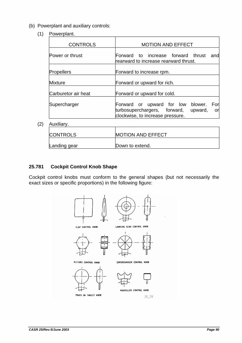
(b) Powerplant and auxiliary controls: (1) Powerplant.
CONTROLS MOTION AND EFFECT
Power or thrust Forward to increase forward thrust and rearward to increase rearward thrust.
Propellers Forward to increase rpm.
Mixture Forward or upward for rich.
Carburetor air heat Forward or upward for cold.
Supercharger Forward or upward for low blower. For turbosuperchargers, forward, upward, or clockwise, to increase pressure.
(2) Auxiliary.
CONTROLS MOTION AND EFFECT
Landing gear Down to extend.
25.781 Cockpit Control Knob Shape
Cockpit control knobs must conform to the general shapes (but not necessarily the exact sizes or specific proportions) in the following figure:
CASR 25/Rev:5/June 2003 Page 90
25.783 Doors
(a) Each cabin must have at least one easily accessible external door.
(b) There must be a means to lock and safeguard each external door against opening in flight (either inadvertently by persons or as a result of mechanical failure or failure of a single structural element either during or after closure). Each external door must be openable from both the inside and the outside, even though persons may be crowded against the door on the inside of the airplane. Inward opening doors may be used if there are means to prevent occupants from crowding against the door to an extent that would interfere with the opening of the door. The means of opening must be simple and obvious and must be arranged and marked so that it can be readily located and operated, even in darkness. Auxiliary locking devices may be used.
(c) Each external door must be reasonably free from jamming as a result of fuselage deformation in a minor crash.
(d) Each external door must be located where persons using them will not be endangered by the propellers when appropriate operating procedures are used.
(e) There must be a provision for direct visual inspection of the locking mechanism to determine if external doors, for which the initial opening movement is not inward (including passenger, crew, service, and cargo doors), are fully closed and locked. The provision must be discernible under operational lighting conditions by appropriate crewmembers using a flashlight or equivalent lighting source. In addition, there must be a visual warning means to signal the appropriate flight crewmembers if any external door is not fully closed and locked. The means must be designed such that any failure or combination of failures that would result in an erroneous closed and locked indication is improbable for doors for which the initial opening movement is not inward.
(f) External doors must have provisions to prevent the initiation of pressurization of the airplane to an unsafe level if the door is not fully closed and locked. In addition, it must be shown by safety analysis that inadvertent opening is extremely improbable.
(g) Cargo and service doors not suitable for use as emergency exits need only meet paragraphs (e) and (f) of this section and be safeguarded against opening in flight as a result of mechanical failure or failure of a single structural element.
(h) Each passenger entry door in the side of the fuselage must meet the applicable requirements of §§ 25.807 through 25.813 for a Type II or larger passenger emergency exit.
(i) If an integral stair is installed in a passenger entry door that is qualified as a passenger emergency exit, the stair must be designed so that under the following conditions the effectiveness of passenger emergency egress will not be impaired: (1) The door, integral stair, and operating mechanism have been subjected to the
inertia forces specified in Sec. 25.561(b)(3), acting separately relative to the surrounding structure.
(2) The airplane is in the normal ground attitude and in each of the attitudes corresponding to collapse of one or more legs of the landing gear.
CASR 25/Rev:5/June 2003 Page 91
(j) All lavatory doors must be designed to preclude anyone from becoming trapped inside the lavatory, and if a locking mechanism is installed, it be capable of being unlocked from the outside without the aid of special tools. [Rev. 25-3, SKEP/145/VI/99, 29 Jun. 1999, ref. FAR Amdt. 25-88]
25.785 Seats, Berths, Safety Belts, and Harnesses
(a) A seat (or berth for a nonambulant person) must be provided for each occupant who has reached his or her second birthday.
(b) Each seat, berth, safety belt, harness, and adjacent part of the airplane at each station designated as occupiable during takeoff and landing must be designed so that a person making proper use of these facilities will not suffer serious injury in an emergency landing as a result of the inertia forces specified in Secs. 25.561 and 25.562.
(c) Each seat or berth must be approved.
(d) Each occupant of a seat that makes more than an 18 degree angle with the vertical plane containing the airplane centerline must be protected from head injury by a safety belt and an energy absorbing rest that will support the arms, shoulders, head, and spine, or by a safety belt and shoulder harness that will prevent the head from contacting any injurious object. Each occupant of any other seat must be protected from head injury by a safety belt and, as appropriate to the type, location, and angle of facing of each seat, by one or more of the following: (1) A shoulder harness that will prevent the head from contacting any injurious
object. (2) The elimination of any injurious object within striking radius of the head. (3) An energy absorbing rest that will support the arms, shoulders, head, and
spine.
(e) Each berth must be designed so that the forward part has a padded end board, canvas diaphragm, or equivalent means, that can withstand the static load reaction of the occupant when subjected to the forward inertial force specified in Sec. 25.561. Berths must be free from corners and protuberances likely to cause injury to a person occupying the berth during emergency conditions.
(f) Each seat or berth, and its supporting structure, and each safety belt or harness and its anchorage must be designed for an occupant weight of 170 pounds, considering the maximum load factors, inertial forces, and reactions among the occupant, seat, safety belt, and harness for each relevant flight and ground load condition (including the emergency landing conditions prescribed in Sec. 25.561). In addition− (1) The structural analysis and testing of the seats, berths, and their supporting
structures may be determined by assuming that the critical load in the forward, sideward, downward, upward, and rearward directions (as determined from the prescribed flight, ground, and emergency landing conditions) acts sepa-rately or using selected combinations of loads if the required strength in each specified direction is substantiated. The forward load factor need not be applied to safety belts for berths.
CASR 25/Rev:5/June 2003 Page 92
(2) Each pilot seat must be designed for the reactions resulting from the application of the pilot forces prescribed in Sec. 25.395.
(3) The inertia forces specified in Sec. 25.561 must be multiplied by a factor of 1.33 (instead of the fitting factor prescribed in Sec. 25.625) in determining the strength of the attachment of each seat to the structure and each belt or harness to the seat or structure.
(g) Each seat at a flight deck station must have a restraint system consisting of a combined safety belt and shoulder harness with a single point release that permits the flight deck occupant, when seated with the restraint system fastened, to perform all of the occupant's necessary flight deck functions. There must be a means to secure each combined restraint system when not in use to prevent interference with the operation of the airplane and with rapid egress in an emergency.
(h) Each seat located in the passenger compartment and designated for use during takeoff and landing by a flight attendant required by the operating rules must be: (1) Near a required floor level emergency exit, except that another location is
acceptable if the emergency egress of passengers would be enhanced with that location. A flight attendant seat must be located adjacent to each Type A or B emergency exit. Other flight attendant seats must be evenly distributed among the required floor-level emergency exits to the extent feasible.
(2) To the extent possible, without compromising proximity to a required floor-level emergency exit, located to provide a direct view of the cabin area for which the flight attendant is responsible.
(3) Positioned so that the seat will not interfere with the use of a passageway or exit when the seat is not in use.
(4) Located to minimize the probability that occupants would suffer injury by being struck by items dislodged from service areas, stowage compartments, or service equipment.
(5) Either forward or rearward facing with an energy absorbing rest that is designed to support the arms, shoulders, head, and spine.
(6) Equipped with a restraint system consisting of a combined safety belt and shoulder harness unit with a single point release. There must be means to secure each restraint system when not in use to prevent interference with rapid egress in an emergency.
(i) Each safety belt must be equipped with a metal to metal latching device.
(j) If the seat backs do not provide a firm handhold, there must be a handgrip or rail along each aisle to enable persons to steady themselves while using the aisles in moderately rough air.
(k) Each projecting object that would injure persons seated or moving about the airplane in normal flight must be padded.
(l) Each forward observer's seat required by the operating rules must be shown to be suitable for use in conducting the necessary enroute inspection. [Rev. 25-3, SKEP/145/VI/99, 29 Jun. 1999, ref. FAR Amdt. 25-88]
CASR 25/Rev:5/June 2003 Page 93
25.787 Stowage Compartments
(a) Each compartment for the stowage of cargo, baggage, carry-on articles, and equipment (such as life rafts), and any other stowage compartment must be designed for its placarded maximum weight of contents and for the critical load distribution at the appropriate maximum load factors corresponding to the specified flight and ground load conditions, and to the emergency landing conditions of Sec. 25.561(b), except that the forces specified in the emergency landing conditions need not be applied to compartments located below, or forward, of all occupants in the airplane. If the airplane has a passenger seating configuration, excluding pilots seats, of 10 seats or more, each stowage compartment in the passenger cabin, except for underseat and overhead compartments for passenger convenience, must be completely enclosed.
(b) There must be a means to prevent the contents in the compartments from becoming a hazard by shifting, under the loads specified in paragraph (a) of this section. For stowage compartments in the passenger and crew cabin, if the means used is a latched door, the design must take into consideration the wear and deterioration expected in service.
(c) If cargo compartment lamps are installed, each lamp must be installed so as to prevent contact between lamp bulb and cargo.
25.789 Retention of Items of Mass in Passenger and Crew Compartments and Galleys
(a) Means must be provided to prevent each item of mass (that is part of the airplane type design) in a passenger or crew compartment or galley from becoming a hazard by shifting under the appropriate maximum load factors corresponding to the specified flight and ground load conditions, and to the emergency landing conditions of Sec. 25.561(b).
(b) Each interphone restraint system must be designed so that when subjected to the load factors specified in Sec. 25.561(b)(3), the interphone will remain in its stowed position.
25.791 Passenger Information Signs and Placards
(a) If smoking is to be prohibited there must be at least one placard so stating that is legible to each person seated in the cabin. If smoking is to be allowed, and if the crew compartment is separated from the passenger compartment, there must be at least one sign notifying when smoking is prohibited. Signs which notify when smoking is prohibited must be operable by a member of the flightcrew and, when illuminated, must be legible under all probable conditions of cabin illumination to each person seated in the cabin.
(b) Signs that notify when seat belts should be fastened and that are installed to comply with the operating rules must be operable by a member of the flightcrew and, when illuminated, must be legible under all probable conditions of cabin illumination to each person seated in the cabin.
CASR 25/Rev:5/June 2003 Page 94
(c) A placard must be located on or adjacent to the door of each receptacle used for the disposal of flammable waste materials to indicate that use of the receptacle for disposal of cigarettes, etc., is prohibited.
(d) Lavatories must have "No Smoking" or "No Smoking in Lavatory" placards conspicuously located on or adjacent to each side of the entry door.
(e) Symbols that clearly express the intent of the sign or placard may be used in lieu of letters.
25.793 Floor Surfaces
The floor surface of all areas which are likely to become wet in service must have slip resistant properties.
EMERGENCY PROVISIONS
25.801 Ditching
(a) If certification with ditching provisions is requested, the airplane must meet the requirements of this section and Secs. 25.807(e), 25.1411, and 25.1415(a).
(b) Each practicable design measure, compatible with the general characteristics of the airplane, must be taken to minimize the probability that in an emergency landing on water, the behavior of the airplane would cause immediate injury to the occupants or would make it impossible for them to escape.
(c) The probable behavior of the airplane in a water landing must be investigated by model tests or by comparison with airplanes of similar configuration for which the ditching characteristics are known. Scoops, flaps, projections, and any other factor likely to affect the hydrodynamic characteristics of the airplane, must be considered.
(d) It must be shown that, under reasonably probable water conditions, the flotation time and trim of the airplane will allow the occupants to leave the airplane and enter the life rafts required by Sec. 25.1415. If compliance with this provision is shown by buoyancy and trim computations, appropriate allowances must be made for probable structural damage and leakage. If the airplane has fuel tanks (with fuel jettisoning provisions) that can reasonably be expected to withstand a ditching without leakage, the jettisonable volume of fuel may be considered as buoyancy volume.
(e) Unless the effects of the collapse of external doors and windows are accounted for in the investigation of the probable behavior of the airplane in a water landing (as prescribed in paragraphs (c) and (d) of this section), the external doors and windows must be designed to withstand the probable maximum local pressures.
25.803 Emergency Evacuation
(a) Each crew and passenger area must have emergency means to allow rapid evacuation in crash landings, with the landing gear extended as well as with the landing gear retracted, considering the possibility of the airplane being on fire.
CASR 25/Rev:5/June 2003 Page 95
(b) [To be determined]
(c) For airplanes having a seating capacity of more than 44 passengers, it must be shown that the maximum seating capacity, including the number of crewmembers required by the operating rules for which certification is requested, can be evacuated from the airplane to the ground under simulated emergency conditions within 90 seconds. Compliance with this requirement must be shown by actual demonstration using the test criteria outlined in appendix J of this attachment unless the Director General finds that a combination of analysis and testing will provide data equivalent to that which would be obtained by actual demonstration.
(d) [To be determined]
(e) [To be determined]
25.807 Passenger Emergency Exits
(a) Type. For the purpose of this attachment, the types of exits are defined as follows: (1) Type I. This type is a floor-level exit with a rectangular opening of not less than
24 inches wide by 48 inches high, with corner radii not greater than eight inches.
(2) Type II. This type is a rectangular opening of not less than 20 inches wide by 44 inches high, with corner radii not greater than seven inches. Type II exits must be floor-level exits unless located over the wing, in which case they must not have a step-up inside the airplane of more than 10 inches nor a step-down outside the airplane of more than 17 inches.
(3) Type III. This type is a rectangular opening of not less than 20 inches wide by 36 inches high with corner radii not greater than seven inches, and with a step-up inside the airplane of not more than 20 inches. If the exit is located over the wing, the step-down outside the airplane may not exceed 27 inches.
(4) Type IV. This type is a rectangular opening of not less than 19 inches wide by 26 inches high, with corner radii not greater than 6.3 inches, located over the wing, with a step-up inside the airplane of not more than 29 inches and a step-down outside the airplane of not more than 36 inches.
(5) Ventral. This type is an exit from the passenger compartment through the pressure shell and the bottom fuselage skin. The dimensions and physical configuration of this type of exit must allow at least the same rate of egress as a Type I exit with the airplane in the normal ground attitude, with landing gear extended.
(6) Tail cone. This type is an aft exit from the passenger compartment through the pressure shell and through an openable cone of the fuselage aft of the pressure shell. The means of opening the tail cone must be simple and obvious and must employ a single operation.
(7) Type A. This type is a floor-level exit with a rectangular opening of not less than 42 inches wide by 72 inches high, with corner radii not greater than seven inches.
(8) Type B. This type is a floor-level exit with a rectangular opening of not less than 32 inches wide by 72 inches high, with corner radii not greater than six inches.
CASR 25/Rev:5/June 2003 Page 96
(9) Type C. This type is a floor-level exit with a rectangular opening of not less than 30 inches wide by 48 inches high, with corner radii not greater than 10 inches.
(b) Step down distance. Step down distance, as used in this section, means the actual distance between the bottom of the required opening and a usable foot hold, extending out from the fuselage, that is large enough to be effective without searching by sight or feel.
(c) Over-sized exits. Openings larger than those specified in this section, whether or not of rectangular shape, may be used if the specified rectangular opening can be inscribed within the opening and the base of the inscribed rectangular opening meets the specified step-up and step-down heights.
(d) Asymmetry. Exits of an exit pair need not be diametrically opposite each other nor of the same size; however, the number of passenger seats permitted under paragraph (g) of this section is based on the smaller of the two exits.
(e) Uniformity. Exits must be distributed as uniformly as practical, taking into account passenger seat distribution.
(f) Location. (1) Each required passenger emergency exit must be accessible to the
passengers and located where it will afford the most effective means of passenger evacuation.
(2) If only one floor-level exit per side is prescribed, and the airplane does not have a tail-cone or ventral emergency exit, the floor-level exits must be in the rearward part of the passenger compartment unless another location affords a more effective means of passenger evacuation.
(3) If more than one floor-level exit per side is prescribed, and the airplane does not have a combination cargo and passenger configuration, at least one floor-level exit must be located in each side near each end of the cabin.
(g) Type and number required. The maximum number of passenger seats permitted depends on the type and number of exits installed in each side of the fuselage. Except as further restricted in paragraphs (g)(1) through (g)(9) of this section, the maximum number of passenger seats permitted for each exit of a specific type installed in each side of the fuselage is as follows: Type A 110 Type B 75 Type C 55 Type I 45 Type II 40 Type III 35 Type IV 9 (1) For a passenger seating configuration of 1 to 9 seats, there must be at least
one Type IV or larger overwing exit in each side of the fuselage or, if overwing
CASR 25/Rev:5/June 2003 Page 97
exits are not provided, at least one exit in each side that meets the minimum dimensions of a Type III exit.
(2) For a passenger seating configuration of more than 9 seats, each exit must be a Type III or larger exit.
(3) For a passenger seating configuration of 10 to 19 seats, there must be at least one Type III or larger exit in each side of the fuselage.
(4) For a passenger seating configuration of 20 to 40 seats, there must be at least two exits, one of which must be a Type II or larger exit, in each side of the fuselage.
(5) For a passenger seating configuration of 41 to 110 seats, there must be at least two exits, one of which must be a Type I or larger exit, in each side of the fuselage.
(6) For a passenger seating configuration of more than 110 seats, the emergency exits in each side of the fuselage must include at least two Type I or larger exits.
(7) The combined maximum number of passenger seats permitted for all Type III exits is 70, and the combined maximum number of passenger seats permitted for two Type III exits in each side of the fuselage that are separated by fewer than three passenger seat rows is 65.
(8) If a Type A, Type B, or Type C exit is installed, there must be at least two Type C or larger exits in each side of the fuselage.
(9) If a passenger ventral or tail cone exit is installed and that exit provides at least the same rate of egress as a Type III exit with the airplane in the most adverse exit opening condition that would result from the collapse of one or more legs of the landing gear, an increase in the passenger seating configuration is permitted as follows: (i) For a ventral exit, 12 additional passenger seats. (ii) For a tail cone exit incorporating a floor level opening of not less than 20
inches wide by 60 inches high, with corner radii not greater than seven inches, in the pressure shell and incorporating an approved assist means in accordance with § 25.810(a), 25 additional passenger seats.
(iii) For a tail cone exit incorporating an opening in the pressure shell which is at least equivalent to a Type III emergency exit with respect to dimensions, step-up and step-down distance, and with the top of the opening not less than 56 inches from the passenger compartment floor, 15 additional passenger seats.
(h) Excess exits. Each emergency exit in the passenger compartment in excess of the minimum number of required emergency exits must meet the applicable requirements of § 25.809 through § 25.812, and must be readily accessible.
(i) Ditching emergency exits for passengers. Whether or not ditching certification is requested, ditching emergency exits must be provided in accordance with the following requirements, unless the emergency exits required by paragraph (g) of this section already meet them: (1) For airplanes that have a passenger seating configuration of nine or fewer
seats, excluding pilot seats, one exit above the waterline in each side of the airplane, meeting at least the dimensions of a Type IV exit.
CASR 25/Rev:5/June 2003 Page 98
(2) For airplanes that have a passenger seating configuration of 10 of more seats, excluding pilot seats, one exit above the waterline in a side of the airplane, meeting at least the dimensions of a Type III exit for each unit (or part of a unit) of 35 passenger seats, but no less than two such exits in the passenger cabin, with one on each side of the airplane. The passenger seat/exit ratio may be increased through the use of larger exits, or other means, provided it is shown that the evacuation capability during ditching has been improved accordingly.
(3) If it is impractical to locate side exits above the waterline, the side exits must be replaced by an equal number of readily accessible overhead hatches of not less than the dimensions of a Type III exit, except that for airplanes with a passenger configuration of 35 or fewer seats, excluding pilot seats, the two required Type III side exits need be replaced by only one overhead hatch. [Rev. 25-3, SKEP/145/VI/99, 29 Jun. 1999, ref. FAR Amdt. 25-88]
25.809 Emergency Exit Arrangement
(a) Each emergency exit, including a flight crew emergency exit, must be a movable door or hatch in the external walls of the fuselage, allowing unobstructed opening to the outside.
(b) Each emergency exit must be openable from the inside and the outside except that sliding window emergency exits in the flight crew area need not be openable from the outside if other approved exits are convenient and readily accessible to the flight crew area. Each emergency exit must be capable of being opened, when there is no fuselage deformation− (1) With the airplane in the normal ground attitude and in each of the attitudes
corresponding to collapse of one or more legs of the landing gear; and (2) Within 10 seconds measured from the time when the opening means is
actuated to the time when the exit is fully opened.
(c) The means of opening emergency exits must be simple and obvious and may not require exceptional effort. Internal exit opening means involving sequence operations (such as operation of two handles or latches or the release of safety catches) may be used for flight crew emergency exits if it can be reasonably established that these means are simple and obvious to crewmembers trained in their use.
(d) If a single power boost or single power operated system is the primary system for operating more than one exit in an emergency, each exit must be capable of meeting the requirements of paragraph (b) of this section in the event of failure of the primary system. Manual operation of the exit (after failure of the primary system) is acceptable.
(e) Each emergency exit must be shown by tests, or by a combination of analysis and tests, to meet the requirements of paragraphs (b) and (c) of this section.
(f) There must be a means to lock each emergency exit and to safeguard against its opening in flight, either inadvertently by persons or as a result of mechanical failure. In addition, there must be a means for direct visual inspection of the locking
CASR 25/Rev:5/June 2003 Page 99
mechanism by crewmembers to determine that each emergency exit, for which the initial opening movement is outward, is fully locked.
(g) There must be provisions to minimize the probability of jamming of the emergency exits resulting from fuselage deformation in a minor crash landing.
(h) When required by the operating rules for any large passenger carrying turbojet powered airplane, each ventral exit and tailcone exit must be− (1) Designed and constructed so that it cannot be opened during flight; and (2) Marked with a placard readable from a distance of 30 inches and installed at a
conspicuous location near the means of opening the exit, stating that the exit has been designed and constructed so that it cannot be opened during flight.
25.810 Emergency Egress Assist Means and Escape Routes
(a) Each non over-wing Type A, Type B or Type C exit, and any other non over-wing landplane emergency exit more than 6 feet from the ground with the airplane on the ground and the landing gear extended, must have an approved means to assist the occupants in descending to the ground. (1) The assisting means for each passenger emergency exit must be a self-
supporting slide or equivalent; and, in the case of Type A or Type B exits, it must be capable of carrying simultaneously two parallel lines of evacuees. In addition, the assisting means must be designed to meet the following requirements− (i) It must be automatically deployed and deployment must begin during
the interval between the time the exit opening means is actuated from inside the airplane and the time the exit is fully opened. However, each passenger emergency exit which is also a passenger entrance door or a service door must be provided with means to prevent deployment of the assisting means when it is opened from either the inside or the outside under nonemergency conditions for normal use.
(ii) Except for assisting means installed at Type C exits, it must be automatically erected within 6 seconds after deployment is begun. Assisting means installed at Type C exits must be automatically erected within 10 seconds from the time the opening means of the exit is actuated.
(iii) It must be of such length after full deployment that the lower end is self-supporting on the ground and provides safe evacuation of occupants to the ground after collapse of one or more legs of the landing gear.
(iv) It must have the capability, in 25 knot winds directed from the most critical angle, to deploy and, with the assistance of only one person, to remain usable after full deployment to evacuate occupants safely to the ground.
(v) For each system installation (mockup or airplane installed), five consecutive deployment and inflation tests must be conducted (per exit) without failure, and at least three tests of each such five-test series must be conducted using a single representative sample of the device. The sample devices must be deployed and inflated by the system's primary means after being subjected to the inertia forces specified in Sec. 25.561(b). If any part of the system fails or does not function properly
CASR 25/Rev:5/June 2003 Page 100
during the required tests, the cause of the failure or malfunction must be corrected by positive means and after that, the full series of five consecutive deployment and inflation tests must be conducted without failure.
(2) The assisting means for flightcrew emergency exits may be a rope or any other means demonstrated to be suitable for the purpose. If the assisting means is a rope, or an approved device equivalent to a rope, it must be− (i) Attached to the fuselage structure at or above the top of the emergency
exit opening, or, for a device at a pilot's emergency exit window, at another approved location if the stored device, or its attachment, would reduce the pilot's view in flight;
(ii) Able (with its attachment) to withstand a 400 pound static load.
(b) Assist means from the cabin to the wing are required for each type A or Type B exit located above the wing and having a stepdown unless the exit without an assist-means can be shown to have a rate of passenger egress at least equal to that of the same type of non over-wing exit. If an assist means is required, it must be automatically deployed and automatically erected concurrent with the opening of the exit. In the case of assist means installed at Type C exits, it must be self-supporting within 10 seconds from the time the opening means of the exits is actuated. For all other exit types, it must be self-supporting 6 seconds after deployment is begun.
(c) An escape route must be established from each overwing emergency exit, and (except for flap surfaces suitable as slides) covered with a slip resistant surface. Except where a means for channeling the flow of evacuees is provided− (1) The escape route from each Type A or Type B passenger emergency exit, or
any common escape route from two Type III passenger emergency exits, must be at least 42 inches wide; that from any other passenger emergency exit must be at least 24 inches wide; and
(2) The escape route surface must have a reflectance of at least 80 percent, and must be defined by markings with a surface-to-marking contrast ratio of at least 5:1.
(d) Means must be provided to assist evacuees to reach the ground for all Type C exits located over the wing and, if the place on the airplane structure at which the escape route required in paragraph (c) of this section terminates is more than 6 feet from the ground with the airplane on the ground and the landing gear extended, for all other exit types. (1) If the escape route is over the flap, the height of the terminal edge must be
measured with the flap in the takeoff or landing position, whichever is higher from the ground.
(2) The assisting means must be usable and self-supporting with one or more landing gear legs collapsed and under a 25-knot wind directed from the most critical angle.
(3) The assisting means provided for each escape route leading from a Type A or B emergency exit must be capable of carrying simultaneously two parallel lines of evacuees; and, the assisting means leading from any other exit type must be capable of carrying as many parallel lines of evacuees as there are required escape routes.
CASR 25/Rev:5/June 2003 Page 101
(4) The assisting means provided for each escape route leading from a Type C exit must be automatically erected within 10 seconds from the time the opening means of the exit is actuated, and that provided for the escape route leading from any other exit type must be automatically erected within 10 seconds after actuation of the erection system.
[Rev. 25-3, SKEP/145/VI/99, 29 Jun. 1999, ref. FAR Amdt. 25-88]
25.811 Emergency Exit Marking
(a) Each passenger emergency exit, its means of access, and its means of opening must be conspicuously marked.
(b) The identity and location of each passenger emergency exit must be recognizable from a distance equal to the width of the cabin.
(c) Means must be provided to assist the occupants in locating the exits in conditions of dense smoke.
(d) The location of each passenger emergency exit must be indicated by a sign visible to occupants approaching along the main passenger aisle (or aisles). There must be− (1) A passenger emergency exit locator sign above the aisle (or aisles) near each
passenger emergency exit, or at another overhead location if it is more practical because of low headroom, except that one sign may serve more than one exit if each exit can be seen readily from the sign;
(2) A passenger emergency exit marking sign next to each passenger emergency exit, except that one sign may serve two such exits if they both can be seen readily from the sign; and
(3) A sign on each bulkhead or divider that prevents fore and aft vision along the passenger cabin to indicate emergency exits beyond and obscured by the bulkhead or divider, except that if this is not possible the sign may be placed at another appropriate location.
(e) The location of the operating handle and instructions for opening exits from the inside of the airplane must be shown in the following manner: (1) Each passenger emergency exit must have, on or near the exit, a marking that
is readable from a distance of 30 inches. (2) Each Type A, Type B, Type C or Type I passenger emergency exit operating
handle must− (i) Be self-illuminated with an initial brightness of at least 160
microlamberts; or (ii) Be conspicuously located and well illuminated by the emergency lighting
even in conditions of occupant crowding at the exit. (3) [To be determined] (4) Each Type A, Type B, Type C, Type I, or Type II passenger emergency exit
with a locking mechanism released by rotary motion of the handle must be marked− (i) With a red arrow, with a shaft at least three-fourths of an inch wide and a
head twice the width of the shaft, extending along at least 70 degrees of arc at a radius approximately equal to three-fourths of the handle length.
CASR 25/Rev:5/June 2003 Page 102
(ii) So that the centerline of the exit handle is within ±1 inch of the projected point of the arrow when the handle has reached full travel and has released the locking mechanism, and
(iii) With the word "open" in red letters 1 inch high, placed horizontally near the head of the arrow.
(f) Each emergency exit that is required to be openable from the outside, and its means of opening, must be marked on the outside of the airplane. In addition, the following apply: (1) The outside marking for each passenger emergency exit in the side of the
fuselage must include a 2 inch colored band outlining the exit. (2) Each outside marking including the band, must have color contrast to be
readily distinguishable from the surrounding fuselage surface. The contrast must be such that if the reflectance of the darker color is 15 percent or less, the reflectance of the lighter color must be at least 45 percent. "Reflectance" is the ratio of the luminous flux reflected by a body to the luminous flux it receives. When the reflectance of the darker color is greater than 15 percent, at least a 30 percent difference between its reflectance and the reflectance of the lighter color must be provided.
(3) In the case of exists other than those in the side of the fuselage, such as ventral or tail cone exists, the external means of opening, including instructions if applicable, must be conspicuously marked in red, or bright chrome yellow if the background color is such that red is inconspicuous. When the opening means is located on only one side of the fuselage, a conspicuous marking to that effect must be provided on the other side.
(g) Each sign required by paragraph (d) of this section may use the word "exit" in its legend in place of the term "emergency exit". [Rev. 25-1, KM. 7 Year 1996, 15 Feb. 1996, ref. FAR Amdt. 25-79; Rev. 25-3, SKEP/145/VI/99, 29 Jun. 1999, ref. FAR Amdt. 25-88]
25.812 Emergency Lighting
(a) An emergency lighting system, independent of the main lighting system, must be installed. However, the sources of general cabin illumination may be common to both the emergency and the main lighting systems if the power supply to the emergency lighting system is independent of the power supply to the main lighting system. The emergency lighting system must include: (1) Illuminated emergency exit marking and locating signs, sources of general
cabin illumination, interior lighting in emergency exit areas, and floor proximity escape path marking.
(2) Exterior emergency lighting.
(b) Emergency exit signs− (1) For airplanes that have a passenger seating configuration, excluding pilot
seats, of 10 seats or more must meet the following requirements: (i) Each passenger emergency exit locator sign required by Sec.
25.811(d)(1) and each passenger emergency exit marking sign required by Sec. 25.811(d)(2) must have red letters at least 1.5 inches high on an
CASR 25/Rev:5/June 2003 Page 103
illuminated white background, and must have an area of at least 21 square inches excluding the letters. The lighted background to letter contrast must be at least 10:1. The letter height to stroke width ratio may not be more than 7:1 nor less than 6:1. These signs must be internally electrically illuminated with a background brightness of at least 25 foot-lamberts and a high to low background contrast no greater than 3:1.
(ii) Each passenger emergency exit sign required by Sec. 25.811(d)(3) must have red letters at least 1.5 inches high on a white background having an area of at least 21 square inches excluding the letters. These signs must be internally electrically illuminated or self-illuminated by other than electrical means and must have an initial brightness of at least 400 microlamberts. The colors may be reversed in the case of a sign that is self-illuminated by other than electrical means.
(2) For airplanes that have a passenger seating configuration, excluding pilot seats, of nine seats or less, that are required by Sec. 25.811(d) (1), (2), and (3) must have red letters at least 1 inch high on a white background at least 2 inches high. These signs may be internally electrically illuminated, or self-illuminated by other than electrical means, with an initial brightness of at least 160 microlamberts. The colors may be reversed in the case of a sign that is self-illuminated by other than electrical means.
(c) General illumination in the passenger cabin must be provided so that when measured along the centerline of main passenger aisle(s), and cross aisle(s) between main aisles, at seat armrest height and at 40 inch intervals, the average illumination is not less than 0.05 foot-candle and the illumination at each 40 inch interval is not less than 0.01 foot-candle. A main passenger aisle(s) is considered to extend along the fuselage from the most forward passenger emergency exit or cabin occupant seat, whichever is farther forward, to the most rearward passenger emergency exit or cabin occupant seat, whichever is farther aft.
(d) The floor of the passageway leading to each floor-level passenger emergency exit, between the main aisles and the exit openings, must be provided with illumination that is not less than 0.02 foot-candle measured along a line that is within 6 inches of and parallel to the floor and is centered on the passenger evacuation path.
(e) Floor proximity emergency escape path marking must provide emergency evacuation guidance for passengers when all sources of illumination more than 4 feet above the cabin aisle floor are totally obscured. In the dark of the night, the floor proximity emergency escape path marking must enable each passenger to− (1) After leaving the passenger seat, visually identify the emergency escape path
along the cabin aisle floor to the first exits or pair of exits forward and aft of the seat; and
(2) Readily identify each exit from the emergency escape path by reference only to markings and visual features not more than 4 feet above the cabin floor.
(f) Except for subsystems provided in accordance with paragraph (h) of this section that serve no more than one assist means, are independent of the airplane's main emergency lighting system, and are automatically activated when the assist means is erected, the emergency lighting system must be designed as follows.
CASR 25/Rev:5/June 2003 Page 104
(1) The lights must be operable manually from the flight crew station and from a point in the passenger compartment that is readily accessible to a normal flight attendant seat.
(2) There must be a flight crew warning light which illuminates when power is on in the airplane and the emergency lighting control device is not armed.
(3) The cockpit control device must have an "on," "off," and "armed" position so that when armed in the cockpit or turned on at either the cockpit or flight attendant station the lights will either light or remain lighted upon interruption (except an interruption caused by a transverse vertical separation of the fuselage during crash landing) of the airplane's normal electric power. There must be a means to safeguard against inadvertent operation of the control device from the "armed" or "on" positions.
(g) Exterior emergency lighting must be provided as follows:
(1) At each overwing emergency exit the illumination must be− (i) Not less than 0.03 foot-candle (measured normal to the direction of the
incident light) on a 2 square foot area where an evacuee is likely to make his first step outside the cabin;
(ii) Not less than 0.05 foot-candle (measured normal to the direction of incident light) along the 30 percent of the slip-resistant portion of the escape route required in § 25.810(c) that is farthest from the exit for the minimum required width of the escape route; and
(iii) Not less than 0.03 foot-candle on the ground surface with the landing gear extended (measured normal to the direction of the incident light) where an evacuee using the established escape route would normally make first contact with the ground.
(2) At each nonoverwing emergency exit not required by Sec. 25.809(f) to have descent assist means the illumination must be not less than 0.03 foot-candle (measured normal to the direction of the incident light) on the ground surface with the landing gear extended where an evacuee is likely to make his first contact with the ground outside the cabin.
(h) The means required in Sec. 25.809 (f)(1) and (h) to assist the occupants in descending to the ground must be illuminated so that the erected assist means is visible from the airplane. (1) If the assist means is illuminated by exterior emergency lighting, it must
provide illumination of not less than 0.03 foot-candle (measured normal to the direction of the incident light) at the ground end of the erected assist means where an evacuee using the established escape route would normally make first contact with the ground, with the airplane in each of the attitudes corresponding to the collapse of one or more legs of the landing gear.
(2) If the emergency lighting subsystem illuminating the assist means serves no other assist means, is independent of the airplane's main emergency lighting system, and is automatically activated when the assist means is erected, the lighting provisions− (i) May not be adversely affected by stowage; and (ii) Must provide illumination of not less than 0.03 foot-candle (measured
normal to the direction of incident light) at the ground and of the erected assist means where an evacuee would normally make first contact with
CASR 25/Rev:5/June 2003 Page 105
the ground, with the airplane in each of the attitudes corresponding to the collapse of one or more legs of the landing gear.
(i) The energy supply to each emergency lighting unit must provide the required level of illumination for at least 10 minutes at the critical ambient conditions after emergency landing.
(j) If storage batteries are used as the energy supply for the emergency lighting system, they may be recharged from the airplane's main electric power system: Provided that, the charging circuit is designed to preclude inadvertent battery discharge into charging circuit faults.
(k) Components of the emergency lighting system, including batteries, wiring relays, lamps, and switches must be capable of normal operation after having been subjected to the inertia forces listed in Sec. 25.561(b).
(l) The emergency lighting system must be designed so that after any single transverse vertical separation of the fuselage during crash landing− (1) Not more than 25 percent of all electrically illuminated emergency lights
required by this section are rendered inoperative, in addition to the lights that are directly damaged by the separation;
(2) Each electrically illuminated exit sign required under Sec. 25.811(d)(2) remains operative exclusive of those that are directly damaged by the separation; and
(3) At least one required exterior emergency light for each side of the airplane remains operative exclusive of those that are directly damaged by the separation.
[Rev. 25-3, SKEP/145/VI/99, 29 Jun. 1999, ref. FAR Amdt. 25-88]
25.813 Emergency Exit Access
Each required emergency exit must be accessible to the passengers and located where it will afford an effective means of evacuation. Emergency exit distribution must be as uniform as practical, taking passenger distribution into account; however, the size and location of exits on both sides of the cabin need not be symmetrical. If only one floor-level exit per side is prescribed, and the airplane does not have a tail cone or ventral emergency exit, the floor-level exit must be in the rearward part of the passenger compartment, unless another location affords a more effective means of passenger evacuation. Where more than one floor-level exit per side is prescribed, at least one floor-level exit per side must be located near each end of the cabin, except that this provision does not apply to combination cargo/passenger configurations. In addition−
(a) There must be a passageway leading from the nearest main aisle to each Type A, Type B, Type C, Type I, or Type II emergency exit and between individual passenger areas. Each passageway leading to a Type A or Type B exit must be unobstructed and at least 36 inches wide. Passageways between individual passenger areas and those leading to Type I, Type II, or Type C emergency exits must be unobstructed and at least 20 inches wide. Unless there are two or more main aisles, each Type A or B exit must be located so that there is passenger flow along the main aisle to that exit from both the forward and aft directions. If two or
CASR 25/Rev:5/June 2003 Page 106
more main aisles are provided, there must be unobstructed cross-aisles at least 20 inches wide between main aisles. There must be - (1) A cross-aisle which leads directly to each passageway between the nearest
main aisle and a Type A or B exit; and (2) A cross aisle which leads to the immediate vicinity of each passageway
between the nearest main aisle and a Type I, Type II, or Type III exit; except that when two Type III exits are located within three passenger rows of each other, a single cross aisle may be used if it leads to the vicinity between the passageways from the nearest main aisle to each exit.
(b) Adequate space to allow crewmember(s) to assist in the evacuation of passengers must be provided as follows: (1) The assist space must not reduce the unobstructed width of the passageway
below that required for the exit. (2) For each Type A or Type B exit, assist space must be provided at each side of
the exit regardless of whether a means is required by § 25.810(a) to assist passengers in descending to the ground from that exit.
(3) Assist space must be provided at one side of any other type exit required by § 25.810(a) to have a means to assist passengers in descending to the ground from that exit.
(c) The following must be provided for each Type III or Type IV exit− (1) There must be access from the nearest aisle to each exit. In addition, for each
Type III exit in an airplane that has a passenger seating configuration of 60 or more− (i) Except as provided in paragraph (c)(1)(ii), the access must be provided
by an unobstructed passageway that is at least 10 inches in width for interior arrangements in which the adjacent seat rows on the exit side of the aisle contain no more than two seats, or 20 inches in width for interior arrangements in which those rows contain three seats. The width of the passageway must be measured with adjacent seats adjusted to their most adverse position. The centerline of the required passageway width must not be displaced more than 5 inches horizontally from that of the exit.
(ii) In lieu of one 10 or 20 inch passageway, there may be two passageways, between seat rows only, that must be at least 6 inches in width and lead to an unobstructed space adjacent to each exit. (Adjacent exits must not share a common passageway.) The width of the passageways must be measured with adjacent seats adjusted to their most adverse position. The unobstructed space adjacent to the exit must extend vertically from the floor to the ceiling (or bottom of sidewall stowage bins), inboard from the exit for a distance not less than the width of the narrowest passenger seat installed on the airplane, and from the forward edge of the forward passageway to the aft edge of the aft passageway. The exit opening must be totally within the fore and aft bounds of the unobstructed space.
(2) In addition to the access− (i) For airplanes that have a passenger seating configuration of 20 or
more, the projected opening of the exit provided must not be obstructed
CASR 25/Rev:5/June 2003 Page 107
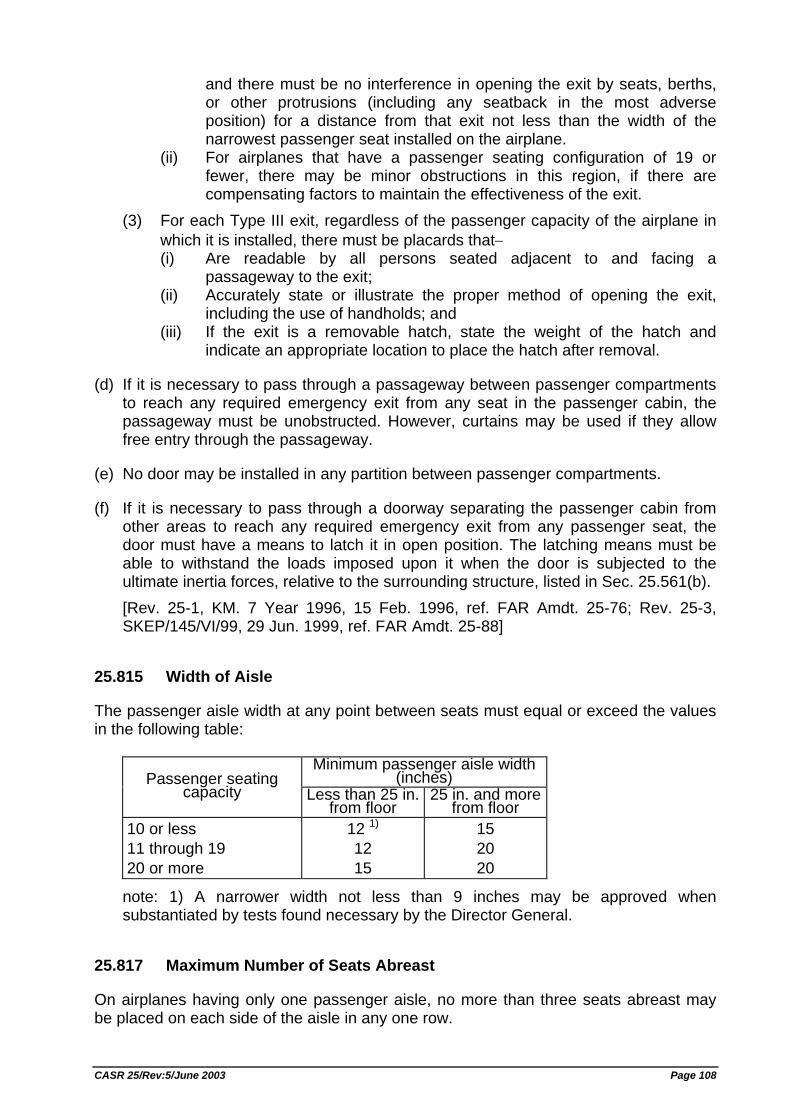
and there must be no interference in opening the exit by seats, berths, or other protrusions (including any seatback in the most adverse position) for a distance from that exit not less than the width of the narrowest passenger seat installed on the airplane.
(ii) For airplanes that have a passenger seating configuration of 19 or fewer, there may be minor obstructions in this region, if there are compensating factors to maintain the effectiveness of the exit.
(3) For each Type III exit, regardless of the passenger capacity of the airplane in which it is installed, there must be placards that− (i) Are readable by all persons seated adjacent to and facing a
passageway to the exit; (ii) Accurately state or illustrate the proper method of opening the exit,
including the use of handholds; and (iii) If the exit is a removable hatch, state the weight of the hatch and
indicate an appropriate location to place the hatch after removal.
(d) If it is necessary to pass through a passageway between passenger compartments to reach any required emergency exit from any seat in the passenger cabin, the passageway must be unobstructed. However, curtains may be used if they allow free entry through the passageway.
(e) No door may be installed in any partition between passenger compartments.
(f) If it is necessary to pass through a doorway separating the passenger cabin from other areas to reach any required emergency exit from any passenger seat, the door must have a means to latch it in open position. The latching means must be able to withstand the loads imposed upon it when the door is subjected to the ultimate inertia forces, relative to the surrounding structure, listed in Sec. 25.561(b). [Rev. 25-1, KM. 7 Year 1996, 15 Feb. 1996, ref. FAR Amdt. 25-76; Rev. 25-3, SKEP/145/VI/99, 29 Jun. 1999, ref. FAR Amdt. 25-88]
25.815 Width of Aisle
The passenger aisle width at any point between seats must equal or exceed the values in the following table:
Minimum passenger aisle width
(inches) Passenger seating capacity Less than 25 in.
from floor 25 in. and more
from floor 10 or less 11 through 19 20 or more
12 1) 12 15
15 20 20
note: 1) A narrower width not less than 9 inches may be approved when substantiated by tests found necessary by the Director General.
25.817 Maximum Number of Seats Abreast
On airplanes having only one passenger aisle, no more than three seats abreast may be placed on each side of the aisle in any one row.
CASR 25/Rev:5/June 2003 Page 108
25.819 Lower Deck Service Compartments (Including Galleys)
For airplanes with a service compartment located below the main deck, which may be occupied during taxi or flight but not during takeoff or landing, the following apply:
(a) There must be at least two emergency evacuation routes, one at each end of each lower deck service compartment or two having sufficient separation within each compartment, which could be used by each occupant of the lower deck service compartment to rapidly evacuate to the main deck under normal and emergency lighting conditions. The routes must provide for the evacuation of incapacitated persons, with assistance. The use of the evacuation routes may not be dependent on any powered device. The routes must be designed to minimize the possibility of blockage which might result from fire, mechanical or structural failure, or persons standing on top of or against the escape routes. In the event the airplane's main power system or compartment main lighting system should fail, emergency illumination for each lower deck service compartment must be automatically provided.
(b) There must be a means for two-way voice communication between the flight deck and each lower deck service compartment.
(c) There must be an aural emergency alarm system, audible during normal and emergency conditions, to enable crewmembers on the flight deck and at each required floor-level emergency exit to alert occupants of each lower deck service compartment of an emergency situation.
(d) There must be a means, readily detectable by occupants of each lower deck service compartment, that indicates when seat belts should be fastened.
(e) If a public address system is installed in the airplane, speakers must be provided in each lower deck service compartment.
(f) For each occupant permitted in a lower deck service compartment, there must be a forward or aft facing seat which meets the requirements of Sec. 25.785(c) and must be able to withstand maximum flight loads when occupied.
(g) For each powered lift system installed between a lower deck service compartment and the main deck for the carriage of persons or equipment, or both, the system must meet the following requirements: (1) Each lift control switch outside the lift, except emergency stop buttons, must
be designed to prevent the activation of the life if the lift door, or the hatch required by paragraph (g)(3) of this section, or both are open.
(2) An emergency stop button, that when activated will immediately stop the lift, must be installed within the lift and at each entrance to the lift.
(3) There must be a hatch capable of being used for evacuating persons from the lift that is openable from inside and outside the lift without tools, with the lift in any position.
CASR 25/Rev:5/June 2003 Page 109
VENTILATION AND HEATING
25.831 Ventilation
(a) Under normal operating conditions and in the event of any probable failure conditions of any system which would adversely affect the ventilating air, the ventilation system must be designed to provide a sufficient amount of uncontaminated air to enable the crewmembers to perform their duties without undue discomfort or fatigue and to provide reasonable passenger comfort. For normal operating conditions, the ventilation system must be designed to provide each occupant with an airflow containing at least 0.55 pounds of fresh air per minute.
(b) Crew and passenger compartment air must be free from harmful or hazardous concentrations of gases or vapors. In meeting this requirement, the following apply: (1) Carbon monoxide concentrations in excess of 1 part in 20,000 parts of air are
considered hazardous. For test purposes, any acceptable carbon monoxide detection method may be used.
(2) Carbon dioxide concentration during flight must be shown not to exceed 0.5 percent by volume (sea level equivalent) in compartments normally occupied by passengers or crewmembers.
(c) There must be provisions made to ensure that the conditions prescribed in paragraph (b) of this section are met after reasonably probable failures or malfunctioning of the ventilating, heating, pressurization, or other systems and equipment.
(d) If accumulation of hazardous quantities of smoke in the cockpit area is reasonably probable, smoke evacuation must be readily accomplished, starting with full pressurization and without depressurizing beyond safe limits.
(e) Except as provided in paragraph (f) of this section, means must be provided to enable the occupants of the following compartments and areas to control the temperature and quantity of ventilating air supplied to their compartment or area independently of the temperature and quantity of air supplied to other compartments and areas: (1) The flight crew compartment. (2) Crewmember compartments and areas other than the flight crew compartment
unless the crewmember compartment or area is ventilated by air interchange with other compartments or areas under all operating conditions.
(f) Means to enable the flight crew to control the temperature and quantity of ventilating air supplied to the flight crew compartment independently of the temperature and quantity of ventilating air supplied to other compartments are not required if all of the following conditions are met: (1) The total volume of the flight crew and passenger compartments is 800 cubic
feet or less. (2) The air inlets and passages for air to flow between flight crew and passenger
compartments are arranged to provide compartment temperatures within 5
CASR 25/Rev:5/June 2003 Page 110
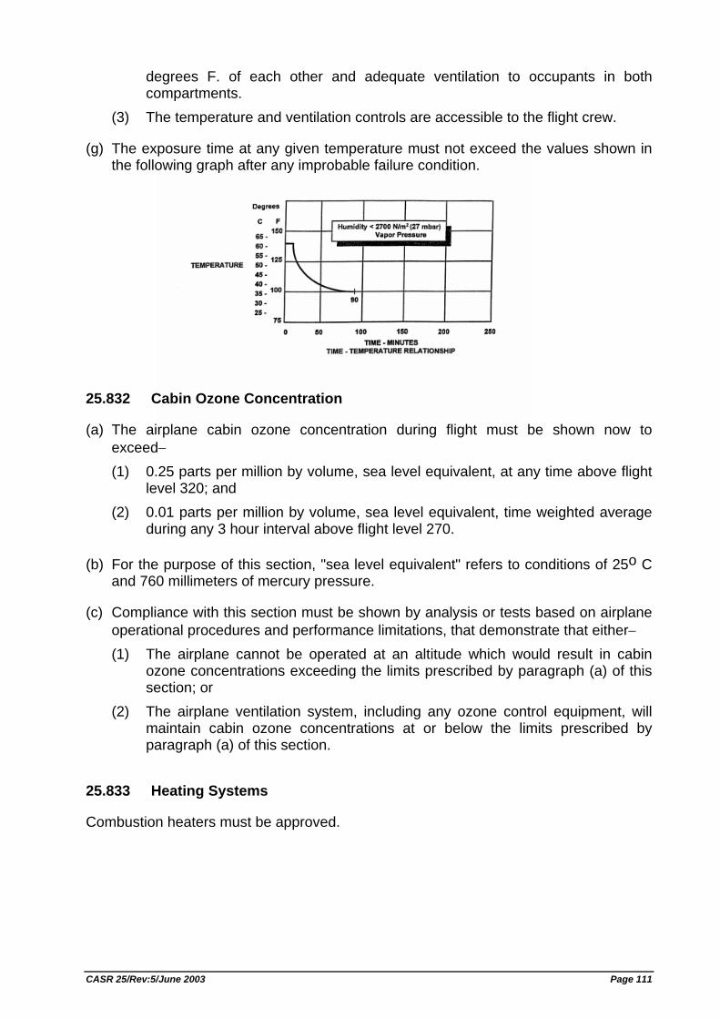
degrees F. of each other and adequate ventilation to occupants in both compartments.
(3) The temperature and ventilation controls are accessible to the flight crew.
(g) The exposure time at any given temperature must not exceed the values shown in the following graph after any improbable failure condition.
25.832 Cabin Ozone Concentration
(a) The airplane cabin ozone concentration during flight must be shown now to exceed− (1) 0.25 parts per million by volume, sea level equivalent, at any time above flight
level 320; and (2) 0.01 parts per million by volume, sea level equivalent, time weighted average
during any 3 hour interval above flight level 270.
(b) For the purpose of this section, "sea level equivalent" refers to conditions of 25o C and 760 millimeters of mercury pressure.
(c) Compliance with this section must be shown by analysis or tests based on airplane operational procedures and performance limitations, that demonstrate that either− (1) The airplane cannot be operated at an altitude which would result in cabin
ozone concentrations exceeding the limits prescribed by paragraph (a) of this section; or
(2) The airplane ventilation system, including any ozone control equipment, will maintain cabin ozone concentrations at or below the limits prescribed by paragraph (a) of this section.
25.833 Heating Systems
Combustion heaters must be approved.
CASR 25/Rev:5/June 2003 Page 111
PRESSURIZATION
25.841 Pressurized Cabins
(a) Pressurized cabins and compartments to be occupied must be equipped to provide a cabin pressure altitude of not more than 8,000 feet at the maximum operating altitude of the airplane under normal operating conditions. (1) If certification for operation above 25,000 feet is requested, the airplane must
be designed so that occupants will not be exposed to cabin pressure altitudes in excess of 15,000 feet after any probable failure condition in the pressurization system.
(2) The airplane must be designed so that occupants will not be exposed to a cabin pressure altitude that exceeds the following after decompression from any failure condition not shown to be extremely improbable: (i) Twenty-five thousand (25,000) feet for more than 2 minutes; or (ii) Forty thousand (40,000) feet for any duration.
(3) Fuselage structure, engine and system failures are to be considered in evaluating the cabin decompression.
(b) Pressurized cabins must have at least the following valves, controls, and indicators for controlling cabin pressure: (1) Two pressure relief valves to automatically limit the positive pressure
differential to a predetermined value at the maximum rate of flow delivered by the pressure source. The combined capacity of the relief valves must be large enough so that the failure of any one valve would not cause an appreciable rise in the pressure differential. The pressure differential is positive when the internal pressure is greater than the external.
(2) Two reverse pressure differential relief valves (or their equivalents) to automatically prevent a negative pressure differential that would damage the structure. One valve is enough, however, if it is of a design that reasonably precludes its malfunctioning.
(3) A means by which the pressure differential can be rapidly equalized. (4) An automatic or manual regulator for controlling the intake or exhaust airflow,
or both, for maintaining the required internal pressures and airflow rates. (5) Instruments at the pilot or flight engineer station to show the pressure
differential, the cabin pressure altitude, and the rate of change of the cabin pressure altitude.
(6) Warning indication at the pilot or flight engineer station to indicate when the safe or preset pressure differential and cabin pressure altitude limits are exceeded. Appropriate warning markings on the cabin pressure differential indicator meet the warning requirement for pressure differential limits and an aural or visual signal (in addition to cabin altitude indicating means) meets the warning requirement for cabin pressure altitude limits if it warns the flight crew when the cabin pressure altitude exceeds 10,000 feet.
(7) A warning placard at the pilot or flight engineer station if the structure is not designed for pressure differentials up to the maximum relief valve setting in combination with landing loads.
CASR 25/Rev:5/June 2003 Page 112
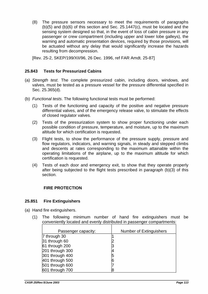
(8) The pressure sensors necessary to meet the requirements of paragraphs (b)(5) and (b)(6) of this section and Sec. 25.1447(c), must be located and the sensing system designed so that, in the event of loss of cabin pressure in any passenger or crew compartment (including upper and lower lobe galleys), the warning and automatic presentation devices, required by those provisions, will be actuated without any delay that would significantly increase the hazards resulting from decompression.
[Rev. 25-2, SKEP/199/XII/96, 26 Dec. 1996, ref FAR Amdt. 25-87]
25.843 Tests for Pressurized Cabins
(a) Strength test. The complete pressurized cabin, including doors, windows, and valves, must be tested as a pressure vessel for the pressure differential specified in Sec. 25.365(d).
(b) Functional tests. The following functional tests must be performed: (1) Tests of the functioning and capacity of the positive and negative pressure
differential valves, and of the emergency release valve, to stimulate the effects of closed regulator valves.
(2) Tests of the pressurization system to show proper functioning under each possible condition of pressure, temperature, and moisture, up to the maximum altitude for which certification is requested.
(3) Flight tests, to show the performance of the pressure supply, pressure and flow regulators, indicators, and warning signals, in steady and stepped climbs and descents at rates corresponding to the maximum attainable within the operating limitations of the airplane, up to the maximum altitude for which certification is requested.
(4) Tests of each door and emergency exit, to show that they operate properly after being subjected to the flight tests prescribed in paragraph (b)(3) of this section.
FIRE PROTECTION
25.851 Fire Extinguishers
(a) Hand fire extinguishers. (1) The following minimum number of hand fire extinguishers must be
conveniently located and evenly distributed in passenger compartments:
Passenger capacity: Number of Extinguishers 7 through 30 31 through 60 61 through 200 201 through 300 301 through 400 401 through 500 501 through 600 601 through 700
1 2 3 4 5 6 7 8
CASR 25/Rev:5/June 2003 Page 113
(2) At least one hand fire extinguisher must be conveniently located in the pilot compartment.
(3) At least one readily accessible hand fire extinguisher must be available for use in each Class A or Class B cargo or baggage compartment and in each Class E cargo or baggage compartment that is accessible to crewmembers in flight.
(4) At least one hand fire extinguisher must be located in, or readily accessible for use in, each galley located above or below the passenger compartment.
(5) Each hand fire extinguisher must be approved. (6) At least one of the required fire extinguishers located in the passenger
compartment of an airplane with a passenger capacity of at least 31 and not more than 60, and at least two of the fire extinguishers located in the passenger compartment of an airplane with a passenger capacity of 61 or more must contain Halon 1211 (bromochlorodifluoromethane CBrC1F2), or equivalent, as the extinguishing agent. The type of extinguishing agent used in any other extinguisher required by this section must be appropriate for the kinds of fires likely to occur where used.
(7) The quantity of extinguishing agent used in each extinguisher required by this section must be appropriate for the kinds of fires likely to occur where used.
(8) Each extinguisher intended for use in a personnel compartment must be designed to minimize the hazard of toxic gas concentration.
(b) Built-in fire extinguishers. If a built-in fire extinguisher is provided−
(1) Each built-in fire extinguishing system must be installed so that− (i) No extinguishing agent likely to enter personnel compartments will be
hazardous to the occupants; and (ii) No discharge of the extinguisher can cause structural damage.
(2) The capacity of each required built-in fire extinguishing system must be adequate for any fire likely to occur in the compartment where used, considering the volume of the compartment and the ventilation rate.
25.853 Compartment Interiors
For each compartment occupied by the crew or passengers, the following apply:
(a) Materials (including finishes or decorative surfaces applied to the materials) must meet the applicable test criteria prescribed in Part I of Appendix F of this Part, or other approved equivalent methods, regardless of the passenger capacity of the airplane.
(b) [Reserved]
(c) In addition to meeting the requirements of paragraph (a) of this section, seat cushions, except those on flight crewmember seats, must meet the test requirements of part II of Appendix F of this Part, or other equivalent methods, regardless of the passenger capacity of the airplane.
(d) Except as provided in paragraph (e) of this section, the following interior components of airplanes with passenger capacities of 20 or more must also meet the test requirements of parts IV and V of Appendix F of this Part, or other approved
CASR 25/Rev:5/June 2003 Page 114
equivalent method, in addition to the flammability requirements prescribed in paragraph (a) of this section: (1) Interior ceiling and wall panels, other than lighting lenses and windows; (2) Partitions, other than transparent panels needed to enhance cabin safety; (3) Galley structure, including exposed surfaces of stowed carts and standard
containers and the cavity walls that are exposed when a full complement of such carts or containers is not carried; and
(4) Large cabinets and cabin stowage compartments, other than underseat stowage compartments for stowing small items such as magazines and maps.
(e) The interiors of compartments, such as pilot compartments, galleys, lavatories, crew rest quarters, cabinets and stowage compartments, need not meet the standards of paragraph (d) of this section, provided the interiors of such compartments are isolated from the main passenger cabin by doors or equivalent means that would normally be closed during an emergency landing condition.
(f) Smoking is not to be allowed in lavatories. If smoking is to be allowed in any other compartment occupied by the crew or passengers, an adequate number of self-contained, removable ashtrays must be provided for all seated occupants.
(g) Regardless of whether smoking is allowed in any other part of the airplane, lavatories must have self-contained, removable ashtrays located conspicuously on or near the entry side of each lavatory door, except that one ashtray may serve more than one lavatory door if the ashtray can be seen readily from the cabin side of each lavatory served.
(h) Each receptacle used for the disposal of flammable waste material must be fully enclosed, constructed of at least fire resistant materials, and must contain fires likely to occur in it under normal use. The capability of the receptacle to contain those fires under all probable conditions of wear, misalignment, and ventilation expected in service must be demonstrated by test. [Rev. 25-2, SKEP/199/XII/96, 26 Dec. 1996, ref FAR Amdt. 25-83]
25.854 Lavatory Fire Protection
For airplanes with a passenger capacity of 20 or more:
(a) Each lavatory must be equipped with a smoke detector system or equivalent that provides a warning light in the cockpit, or provides a warning light or audible warning in the passenger cabin that would be readily detected by a flight attendant; and
(b) Each lavatory must be equipped with a built-in fire extinguisher for each disposal receptacle for towels, paper, or waste, located within the lavatory. The extinguisher must be designed to discharge automatically into each disposal receptacle upon occurrence of a fire in that receptacle.
CASR 25/Rev:5/June 2003 Page 115
25.855 Cargo and Baggage Compartments
For each cargo and baggage compartment not occupied by crew or passengers, the following apply:
(a) The compartment must meet one of the class requirements of Sec. 25.857.
(b) The Class B through Class E cargo or baggage compartments, as defined in Sec. 25.857, must have a liner, and the liner must be separate from (but may be attached to) the airplane structure.
(c) Ceiling and sidewall liner panels of Class C and D compartments must meet the test requirements of part III of appendix F of this attachment or other approved equivalent methods.
(d) All other materials used in the construction of the cargo or baggage compartment must meet the applicable test criteria prescribed in part I of appendix F of this attachment or other approved equivalent methods.
(e) No compartment may contain any controls, wiring, lines, equipment, or accessories whose damage or failure would affect safe operation, unless those items are protected so that− (1) They cannot be damaged by the movement of cargo in the compartment, and (2) Their breakage or failure will not create a fire hazard.
(f) There must be means to prevent cargo or baggage from interfering with the functioning of the fire protective features of the compartment.
(g) Sources of heat within the compartment must be shielded and insulated to prevent igniting the cargo or baggage.
(h) Flight test must be conducted to show compliance with the provisions of Sec. 25.857 concerning− (1) Compartment accessibility, (2) The entries of hazardous quantities of smoke or extinguishing agent into
compartments occupied by the crew or passengers, and (3) The dissipation of the extinguishing agent in Class C compartments.
(i) During the above tests, it must be shown that no inadvertent operation of smoke or fire detectors in any compartment would occur as a result of fire contained in any other compartment, either during or after extinguishment, unless the extinguishing system floods each such compartment simultaneously.
25.857 Cargo compartment classification.
(a) Class A. A Class A cargo or baggage compartment is one in which− (1) The presence of a fire would be easily discovered by a crewmember while at
his station; and (2) Each part of the compartment is easily accessible in flight.
CASR 25/Rev:5/June 2003 Page 116
(b) Class B. A Class B cargo or baggage compartment is one in which− (1) There is sufficient access in flight to enable a crewmember to effectively reach
any part of the compartment with the contents of a hand fire extinguisher; (2) When the access provisions are being used, no hazardous quantity of smoke,
flames, or extinguishing agent, will enter any compartment occupied by the crew or passengers;
(3) There is a separate approved smoke detector or fire detector system to give warning at the pilot or flight engineer station.
(c) Class C. A Class C cargo or baggage compartment is one not meeting the requirements for either a Class A or B compartment but in which− (1) There is a separate approved smoke detector or fire detector system to give
warning at the pilot or flight engineer station; (2) There is an approved built-in fire extinguishing system controllable from the
pilot or flight engineer stations; (3) There are means to exclude hazardous quantities of smoke, flames, or
extinguishing agent, from any compartment occupied by the crew or passengers;
(4) There are means to control ventilation and drafts within the compartment so that the extinguishing agent used can control any fire that may start within the compartment.
(d) Class D. A Class D cargo or baggage compartment is one in which− (1) A fire occurring in it will be completely confined without endangering the safety
of the airplane or the occupants; (2) There are means to exclude hazardous quantities of smoke, flames, or other
noxious gases, from any compartment occupied by the crew or passengers; (3) Ventilation and drafts are controlled within each compartment so that any fire
likely to occur in the compartment will not progress beyond safe limits; and (4) [To be determined] (5) Consideration is given to the effect of heat within the compartment on adjacent
critical parts of the airplane. For compartments of 500 cu. ft. or less, an airflow of 1500 cu. ft. per hour is acceptable.
(6) The compartment volume does not exceed 1,000 cubic feet.
(e) Class E. A Class E cargo compartment is one on airplanes used only for the carriage of cargo and in which− (1) [To be determined] (2) There is a separate approved smoke or fire detector system to give warning at
the pilot or flight engineer station; (3) There are means to shut off the ventilating airflow to, or within, the
compartment, and the controls for these means are accessible to the flight crew in the crew compartment;
(4) There are means to exclude hazardous quantities of smoke, flames, or noxious gases, from the flight crew compartment; and
CASR 25/Rev:5/June 2003 Page 117
(5) The required crew emergency exits are accessible under any cargo loading condition.
25.858 Cargo Compartment Fire Detection Systems
If certification with cargo compartment fire detection provisions is requested, the following must be met for each cargo compartment with those provisions:
(a) The detection system must provide a visual indication to the flight crew within one minute after the start of a fire.
(b) The system must be capable of detecting a fire at a temperature significantly below that at which the structural integrity of the airplane is substantially decreased.
(c) There must be means to allow the crew to check in flight, the functioning of each fire detector circuit.
(d) The effectiveness of the detection system must be shown for all approved operating configurations and conditions.
25.859 Combustion Heater Fire Protection
(a) Combustion heater fire zones. The following combustion heater fire zones must be protected from fire in accordance with the applicable provisions of Secs. 25.1181 through 25.1191 and Secs. 25.1195 through 25.1203; (1) The region surrounding the heater, if this region contains any flammable fluid
system components (excluding the heater fuel system), that could− (i) Be damaged by heater malfunctioning; or (ii) Allow flammable fluids or vapors to reach the heater in case of leakage.
(2) The region surrounding the heater, if the heater fuel system has fittings that, if they leaked, would allow fuel or vapors to enter this region.
(3) The part of the ventilating air passage that surrounds the combustion chamber. However, no fire extinguishment is required in cabin ventilating air passages.
(b) Ventilating air ducts. Each ventilating air duct passing through any fire zone must be fireproof. In addition− (1) Unless isolation is provided by fireproof valves or by equally effective means,
the ventilating air duct downstream of each heater must be fireproof for a distance great enough to ensure that any fire originating in the heater can be contained in the duct; and
(2) Each part of any ventilating duct passing through any region having a flammable fluid system must be constructed or isolated from that system so that the malfunctioning of any component of that system cannot introduce flammable fluids or vapors into the ventilating airstream.
(c) Combustion air ducts. Each combustion air duct must be fireproof for a distance great enough to prevent damage from backfiring or reverse flame propagation. In addition−
CASR 25/Rev:5/June 2003 Page 118
(1) No combustion air duct may have a common opening with the ventilating airstream unless flames from backfires or reverse burning cannot enter the ventilating airstream under any operating condition, including reverse flow or malfunctioning of the heater or its associated components; and
(2) No combustion air duct may restrict the prompt relief of any backfire that, if so restricted, could cause heater failure.
(d) Heater controls; general. Provision must be made to prevent the hazardous accumulation of water or ice on or in any heater control component, control system tubing, or safety control.
(e) Heater safety controls. For each combustion heater there must be the following safety control means: (1) Means independent of the components provided for the normal continuous
control of air temperature, airflow, and fuel flow must be provided, for each heater, to automatically shut off the ignition and fuel supply to that heater at a point remote from that heater when any of the following occurs: (i) The heat exchanger temperature exceeds safe limits. (ii) The ventilating air temperature exceeds safe limits. (iii) The combustion airflow becomes inadequate for safe operation. (iv) The ventilating airflow becomes inadequate for safe operation.
(2) The means of complying with paragraph (e)(1) of this section for any individual heater must− (i) Be independent of components serving any other heater whose heat
output is essential for safe operation; and (ii) Keep the heater off until restarted by the crew.
(3) There must be means to warn the crew when any heater whose heat output is essential for safe operation has been shut off by the automatic means prescribed in paragraph (e)(1) of this section.
(f) Air intakes. Each combustion and ventilating air intake must be located so that no flammable fluids or vapors can enter the heater system under any operating condition− (1) During normal operation; or (2) As a result of the malfunctioning of any other component.
(g) Heater exhaust. Heater exhaust systems must meet the provisions of Secs. 25.1121 and 25.1123. In addition, there must be provisions in the design of the heater exhaust system to safely expel the products of combustion to prevent the occurrence of− (1) Fuel leakage from the exhaust to surrounding compartments; (2) Exhaust gas impingement on surrounding equipment or structure; (3) Ignition of flammable fluids by the exhaust, if the exhaust is in a compartment
containing flammable fluid lines; and (4) Restriction by the exhaust of the prompt relief of backfires that, if so restricted,
could cause heater failure.
CASR 25/Rev:5/June 2003 Page 119
(h) Heater fuel systems. Each heater fuel system must meet each powerplant fuel system requirement affecting safe heater operation. Each heater fuel system component within the ventilating airstream must be protected by shrouds so that no leakage from those components can enter the ventilating airstream.
(i) Drains. There must be means to safely drain fuel that might accumulate within the combustion chamber or the heat exchanger. In addition− (1) Each part of any drain that operates at high temperatures must be protected in
the same manner as heater exhausts; and (2) Each drain must be protected from hazardous ice accumulation under any
operating condition.
25.863 Flammable Fluid Fire Protection
(a) In each area where flammable fluids or vapors might escape by leakage of a fluid system, there must be means to minimize the probability of ignition of the fluids and vapors, and the resultant hazards if ignition does occur.
(b) Compliance with paragraph (a) of this section must be shown by analysis or tests, and the following factors must be considered: (1) Possible sources and paths of fluid leakage, and means of detecting leakage. (2) Flammability characteristics of fluids, including effects of any combustible or
absorbing materials. (3) Possible ignition sources, including electrical faults, overheating of equipment,
and malfunctioning of protective devices. (4) Means available for controlling or extinguishing a fire, such as stopping flow of
fluids, shutting down equipment, fireproof containment, or use of extinguishing agents.
(5) Ability of airplane components that are critical to safety of flight to withstand fire and heat.
(c) If action by the flight crew is required to prevent or counteract a fluid fire (e.g., equipment shutdown or actuation of a fire extinguisher) quick acting means must be provided to alert the crew.
(d) Each area where flammable fluids or vapors might escape by leakage of a fluid system must be identified and defined.
25.865 Fire Protection of Flight Controls, Engine Mounts, and Other Flight Structure
Essential flight controls, engine mounts, and other flight structures located in designated fire zones or in adjacent areas which would be subjected to the effects of fire in the fire zone must be constructed of fireproof material or shielded so that they are capable of withstanding the effects of fire.
CASR 25/Rev:5/June 2003 Page 120
25.867 Fire Protection: Other Components
(a) Surfaces to the rear of the nacelles, within one nacelle diameter of the nacelle centerline, must be at least fire resistant.
(b) Paragraph (a) of this section does not apply to tail surfaces to the rear of the nacelles that could not be readily affected by heat, flames, or sparks coming from a designated fire zone or engine compartment of any nacelle.
25.869 Fire Protection: Systems
(a) Electrical system components: (1) Components of the electrical system must meet the applicable fire and smoke
protection requirements of Secs. 25.831(c) and 25.863. (2) Electrical cables, terminals, and equipment in designated fire zones, that are
used during emergency procedures, must be at least fire resistant. (3) Main power cables (including generator cables) in the fuselage must be
designed to allow a reasonable degree of deformation and stretching without failure and must be− (i) Isolated from flammable fluid lines; or (ii) Shrouded by means of electrically insulated, flexible conduit, or
equivalent, which is in addition to the normal cable insulation. (4) Insulation on electrical wire and electrical cable installed in any area of the
fuselage must be self-extinguishing when tested in accordance with the applicable portions of part I, appendix F of this attachment.
(b) Each vacuum air system line and fitting on the discharge side of the pump that might contain flammable vapors or fluids must meet the requirements of Sec. 25.1183 if the line or fitting is in a designated fire zone. Other vacuum air systems components in designated fire zones must be at least fire resistant.
(c) Oxygen equipment and lines must− (1) Not be located in any designated fire zone, (2) Be protected from heat that may be generated in, or escape from, any
designated fire zone, and (3) Be installed so that escaping oxygen cannot cause ignition of grease, fluid, or
vapor accumulations that are present in normal operation or as a result of failure or malfunction of any system.
MISCELLANEOUS
25.871 Leveling Means
There must be means for determining when the airplane is in a level position on the ground.
CASR 25/Rev:5/June 2003 Page 121
25.875 Reinforcement Near Propellers
(a) Each part of the airplane near the propeller tips must be strong and stiff enough to withstand the effects of the induced vibration and of ice thrown from the propeller.
(b) No window may be near the propeller tips unless it can withstand the most severe ice impact likely to occur.
CASR 25/Rev:5/June 2003 Page 122
Subpart E - Powerplant
GENERAL
25.901 Installation.
(a) For the purpose of this attachment, the airplane powerplant installation includes each component that− (1) Is necessary for propulsion; (2) Affects the control of the major propulsive units; or (3) Affects the safety of the major propulsive units between normal inspections or
overhauls.
(b) For each powerplant−
(1) The installation must comply with− (i) The installation instructions provided under Sec. 33.5 of Attachment VII
of this Decree; and (ii) The applicable provisions of this subpart;
(2) The components of the installation must be constructed, arranged, and installed so as to ensure their continued safe operation between normal inspections or overhauls;
(3) The installation must be accessible for necessary inspections and maintenance; and
(4) The major components of the installation must be electrically bonded to the other parts of the airplane.
(c) For each powerplant and auxiliary power unit installation, it must be established that no single failure or malfunction or probable combination of failures will jeopardize the safe operation of the airplane except that the failure of structural elements need not be considered if the probability of such failure is extremely remote.
(d) Each auxiliary power unit installation must meet the applicable provisions of this subpart.
25.903 Engines
(a) Engine type certificate. (1) Each engine must have a type certificate and must meet the applicable
requirements of Attachment VIII of this Decree.
(2) Each turbine engine must either− (i) Comply with Sec. 33.77 of Attachment VII of this Decree; or (ii) Be shown to have a foreign object ingestion service history in similar
installation locations which has not resulted in any unsafe condition.
CASR 25/Rev:5/June 2003 Page 123
(b) Engine isolation. The powerplants must be arranged and isolated from each other to allow operation, in at least one configuration, so that the failure or malfunction of any engine, or of any system that can affect the engine, will not− (1) Prevent the continued safe operation of the remaining engines; or (2) Require immediate action by any crewmember for continued safe operation.
(c) Control of engine rotation. There must be means for stopping the rotation of any engine individually in flight, except that, for turbine engine installations, the means for stopping the rotation of any engine need be provided only where continued rotation could jeopardize the safety of the airplane. Each component of the stopping and restarting system on the engine side of the firewall that might be exposed to fire must be at least fire resistant. If hydraulic propeller feathering systems are used for this purpose, the feathering lines must be at least fire resistant under the operating conditions that may be expected to exist during feathering.
(d) Turbine engine installations. For turbine engine installations− (1) Design precautions must be taken to minimize the hazards to the airplane in
the event of an engine rotor failure or of a fire originating within the engine which burns through the engine case.
(2) The powerplant systems associated with engine control devices, systems, and instrumentation, must be designed to give reasonable assurance that those engine operating limitations that adversely affect turbine rotor structural integrity will not be exceeded in service.
(e) Restart capability. (1) Means to restart any engine in flight must be provided. (2) An altitude and airspeed envelope must be established for in-flight engine
restarting, and each engine must have a restart capability within that envelope. (3) For turbine engine powered airplanes, if the minimum windmilling speed of the
engines, following the inflight shutdown of all engines, is insufficient to provide the necessary electrical power for engine ignition, a power source independent of the engine driven electrical power generating system must be provided to permit in-flight engine ignition for restarting.
(f) Auxiliary Power Unit. Each auxiliary power unit must be approved or meet the requirements of the category for its intended use.
25.904 Automatic Takeoff Thrust Control System (ATTCS)
Each applicant seeking approval for installation of an engine power control system that automatically resets the power or thrust on the operating engine(s) when any engine fails during the takeoff must comply with the requirements of Appendix I of this attachment.
25.905 Propellers
(a) Each propeller must have a type certificate.
CASR 25/Rev:5/June 2003 Page 124
(b) Engine power and propeller shaft rotational speed may not exceed the limits for which the propeller is certificated.
(c) Each component of the propeller blade pitch control system must meet the requirements of Sec. 35.42 of Attachment IX of this Decree.
(d) Design precautions must be taken to minimize the hazards to the airplane in the event a propeller blade fails or is released by a hub failure. The hazards which must be considered include damage to structure and vital systems due to impact of a failed or released blade and the unbalance created by such failure or release.
25.907 Propeller Vibration
(a) The magnitude of the propeller blade vibration stresses under any normal condition of operation must be determined by actual measurement or by comparison with similar installations for which these measurements have been made.
(b) The determined vibration stresses may not exceed values that have been shown to be safe for continuous operation.
25.925 Propeller Clearance
Unless smaller clearances are substantiated, propeller clearances with the airplane at maximum weight, with the most adverse center of gravity, and with the propeller in the most adverse pitch position, may not be less than the following:
(a) Ground clearance. There must be a clearance of at least seven inches (for each airplane with nose wheel landing gear) or nine inches (for each airplane with tail wheel landing gear) between each propeller and the ground with the landing gear statically deflected and in the level takeoff, or taxiing attitude, whichever is most critical. In addition, there must be positive clearance between the propeller and the ground when in the level takeoff attitude with the critical tire(s) completely deflated and the corresponding landing gear strut bottomed.
(b) Water clearance. There must be a clearance of at least 18 inches between each propeller and the water, unless compliance with Sec. 25.239(a) can be shown with a lesser clearance.
(c) Structural clearance. There must be− (1) At least one inch radial clearance between the blade tips and the airplane
structure, plus any additional radial clearance necessary to prevent harmful vibration;
(2) At least one-half inch longitudinal clearance between the propeller blades or cuffs and stationary parts of the airplane; and
(3) Positive clearance between other rotating parts of the propeller or spinner and stationary parts of the airplane.
CASR 25/Rev:5/June 2003 Page 125
25.929 Propeller Deicing
(a) For airplanes intended for use where icing may be expected, there must be a means to prevent or remove hazardous ice accumulation on propellers or on accessories where ice accumulation would jeopardize engine performance.
(b) If combustible fluid is used for propeller deicing, Secs. 25.1181 through 25.1185 and 25.1189 apply.
25.933 Reversing Systems
(a) For turbojet reversing systems− (1) Each system intended for ground operation only must be designed so that
during any reversal in flight the engine will produce no more than flight idle thrust. In addition, it must be shown by analysis or test, or both, that− (i) Each operable reverser can be restored to the forward thrust position;
and (ii) The airplane is capable of continued safe flight and landing under any
possible position of the thrust reverser. (2) Each system intended for in-flight use must be designed so that no unsafe
condition will result during normal operation of the system, or from any failure (or reasonably likely combination of failures) of the reversing system, under any anticipated condition of operation of the airplane including ground operation. Failure of structural elements need not be considered if the probability of this kind of failure is extremely remote.
(3) Each system must have means to prevent the engine from producing more than idle thrust when the reversing system malfunctions, except that it may produce any greater forward thrust that is shown to allow directional control to be maintained, with aerodynamic means alone, under the most critical reversing condition expected in operation.
(b) For propeller reversing systems− (1) Each system intended for ground operation only must be designed so that no
single failure (or reasonably likely combination of failures) or malfunction of the system will result in unwanted reverse thrust under any expected operating condition. Failure of structural elements need not be considered if this kind of failure is extremely remote.
(2) Compliance with this section may be shown by failure analysis or testing, or both, for propeller systems that allow propeller blades to move from the flight low-pitch position to a position that is substantially less than that at the normal flight low-pitch position. The analysis may include or be supported by the analysis made to show compliance with the requirements of Sec. 35.21 of Attachment IX of this Decree for the propeller and associated installation components.
25.934 Turbojet Engine Thrust Reverser System Tests
Thrust reversers installed on turbojet engines must meet the requirements of Sec. 33.97 of Attachment VII of this Decree.
CASR 25/Rev:5/June 2003 Page 126
25.937 Turbopropeller Drag Limiting Systems
Turbopropeller power airplane propeller drag limiting systems must be designed so that no single failure or malfunction of any of the systems during normal or emergency operation results in propeller drag in excess of that for which the airplane was designed under Sec. 25.367. Failure of structural elements of the drag limiting systems need not be considered if the probability of this kind of failure is extremely remote.
25.939 Turbine Engine Operating Characteristics
(a) Turbine engine operating characteristics must be investigated in flight to determine that no adverse characteristics (such as stall, surge, or flameout) are present, to a hazardous degree, during normal and emergency operation within the range of operating limitations of the airplane and of the engine.
(b) [To be determined]
(c) The turbine engine air inlet system may not, as a result of air flow distortion during normal operation, cause vibration harmful to the engine.
25.941 Inlet, Engine, and Exhaust Compatibility
For airplanes using variable inlet or exhaust system geometry, or both−
(a) The system comprised of the inlet, engine (including thrust augmentation systems, if incorporated), and exhaust must be shown to function properly under all operating conditions for which approval is sought, including all engine rotating speeds and power settings, and engine inlet and exhaust configurations;
(b) The dynamic effects of the operation of these (including consideration of probable malfunctions) upon the aerodynamic control of the airplane may not result in any condition that would require exceptional skill, alertness, or strength on the part of the pilot to avoid exceeding an operational or structural limitation of the airplane; and
(c) In showing compliance with paragraph (b) of this section, the pilot strength required may not exceed the limits set forth in Sec. 25.143(c), subject to the conditions set forth in paragraphs (d) and (e) of Sec. 25.143.
25.943 Negative Acceleration
No hazardous malfunction of an engine, an auxiliary power unit approved for use in flight, or any component or system associated with the powerplant or auxiliary power unit may occur when the airplane is operated at the negative accelerations within the flight envelopes prescribed in Sec. 25.333. This must be shown for the greatest duration expected for the acceleration.
25.945 Thrust or Power Augmentation System
(a) General. Each fluid injection system must provide a flow of fluid at the rate and pressure established for proper engine functioning under each intended operating
CASR 25/Rev:5/June 2003 Page 127
condition. If the fluid can freeze, fluid freezing may not damage the airplane or adversely affect airplane performance.
(b) Fluid tanks. Each augmentation system fluid tank must meet the following requirements: (1) Each tank must be able to withstand without failure the vibration, inertia, fluid,
and structural loads that is may be subject to in operation. (2) The tanks as mounted in the airplane must be able to withstand without failure
or leakage an internal pressure 1.5 times the maximum operating pressure. (3) If a vent is provided, the venting must be effective under all normal flight
conditions. (4) [To be determined].
(c) Augmentation system drains must be designed and located in accordance with Sec. 25.1455 if− (1) The augmentation system fluid is subject to freezing; and (2) The fluid may be drained in flight or during ground operation.
(d) The augmentation liquid tank capacity available for the use of each engine must be large enough to allow operation of the airplane under the approved procedures for the use of liquid augmented power. The computation of liquid consumption must be based on the maximum approved rate appropriate for the desired engine output and must include the effect of temperature on engine performance as well as any other factors that might vary the amount of liquid required.
(e) This section does not apply to fuel injection systems.
FUEL SYSTEM
25.951 General
(a) Each fuel system must be constructed and arranged to ensure a flow of fuel at a rate and pressure established for proper engine and auxiliary power unit functioning under each likely operating condition, including any maneuver for which certification is requested and during which the engine or auxiliary power unit is permitted to be in operation.
(b) Each fuel system must be arranged so that any air which is introduced into the system will not result in− (1) Power interruption for more than 20 seconds for reciprocating engines; or (2) Flameout for turbine engines.
(c) Each fuel system for a turbine engine must be capable of sustained operation throughout its flow and pressure range with fuel initially saturated with water at 80o F and having 0.75 cc of free water per gallon added and cooled to the most critical condition for icing likely to be encountered in operation.
CASR 25/Rev:5/June 2003 Page 128
(d) Each fuel system for a turbine engine powered airplane must meet the applicable fuel venting requirements of Attachment VIII.
25.952 Fuel System Analysis and Test
(a) Proper fuel system functioning under all probable operating conditions must be shown by analysis and those tests found necessary by the Director General. Tests, if required, must be made using the airplane fuel system or a test article that reproduces the operating characteristics of the portion of the fuel system to be tested.
(b) The likely failure of any heat exchanger using fuel as one of its fluids may not result in a hazardous condition.
25.953 Fuel System Independence
Each fuel system must meet the requirements of Sec. 25.903(b) by−
(a) Allowing the supply of fuel to each engine through a system independent of each part of the system supplying fuel to any other engine; or
(b) Any other acceptable method.
25.954 Fuel System Lightning Protection
The fuel system must be designed and arranged to prevent the ignition of fuel vapor within the system by−
(a) Direct lightning strikes to areas having a high probability of stroke attachment;
(b) Swept lightning strokes to areas where swept strokes are highly probable; and
(c) Corona and streamering at fuel vent outlets.
25.955 Fuel Flow
(a) Each fuel system must provide at least 100 percent of the fuel flow required under each intended operating condition and maneuver. Compliance must be shown as follows: (1) Fuel must be delivered to each engine at a pressure within the limits specified
in the engine type certificate. (2) The quantity of fuel in the tank may not exceed the amount established as the
unusable fuel supply for that tank under the requirements of Sec. 25.959 plus that necessary to show compliance with this section.
(3) Each main pump must be used that is necessary for each operating condition and attitude for which compliance with this section is shown, and the appropriate emergency pump must be substituted for each main pump so used.
CASR 25/Rev:5/June 2003 Page 129
(4) If there is a fuel flowmeter, it must be blocked and the fuel must flow through the meter or its bypass.
(b) If an engine can be supplied with fuel from more than one tank, the fuel system must− (1) For each reciprocating engine, supply the full fuel pressure to that engine in
not more than 20 seconds after switching to any other fuel tank containing usable fuel when engine malfunctioning becomes apparent due to the depletion of the fuel supply in any tank from which the engine can be fed; and
(2) For each turbine engine, in addition to having appropriate manual switching capability, be designed to prevent interruption of fuel flow to that engine, without attention by the flight crew, when any tank supplying fuel to that engine is depleted of usable fuel during normal operation, and any other tank, that normally supplies fuel to that engine alone, contains usable fuel.
25.957 Flow between Interconnected Tanks
If fuel can be pumped from one tank to another in flight, the fuel tank vents and the fuel transfer system must be designed so that no structural damage to the tanks can occur because of overfilling.
25.959 Unusable Fuel supply
The unusable fuel quantity for each fuel tank and its fuel system components must be established at not less than the quantity at which the first evidence of engine malfunction occurs under the most adverse fuel feed condition for all intended operations and flight maneuvers involving fuel feeding from that tank. Fuel system component failures need not be considered.
25.961 Fuel System Hot Weather Operation
(a) The fuel system must perform satisfactorily in hot weather operation. This must be shown by showing that the fuel system from the tank outlets to each engine is pressurized, under all intended operations, so as to prevent vapor formation, or must be shown by climbing from the altitude of the airport elected by the applicant to the maximum altitude established as an operating limitation under Sec. 25.1527. If a climb test is elected, there may be no evidence of vapor lock or other malfunctioning during the climb test conducted under the following conditions: (1) For reciprocating engine powered airplanes, the engines must operate at
maximum continuous power, except that takeoff power must be used for the altitudes from 1,000 feet below the critical altitude through the critical altitude. The time interval during which takeoff power is used may not be less than the takeoff time limitation.
(2) For turbine engine powered airplanes, the engines must operate at takeoff power for the time interval selected for showing the takeoff flight path, and at maximum continuous power for the rest of the climb.
CASR 25/Rev:5/June 2003 Page 130
(3) The weight of the airplane must be the weight with full fuel tanks, minimum crew, and the ballast necessary to maintain the center of gravity within allowable limits.
(4)The climb airspeed may not exceed− (i) For reciprocating engine powered airplanes, the maximum airspeed
established for climbing from takeoff to the maximum operating altitude with the airplane in the following configuration: (A) Landing gear retracted. (B) Wing flaps in the most favorable position. (C) Cowl flaps (or other means of controlling the engine cooling
supply) in the position that provides adequate cooling in the hot day condition.
(D) Engine operating within the maximum continuous power limitations.
(E) Maximum takeoff weight; and (ii) For turbine engine powered airplanes, the maximum airspeed
established for climbing from takeoff to the maximum operating altitude.
(5) The fuel temperature must be at least 110o F.
(b) The test prescribed in paragraph (a) of this section may be performed in flight or on the ground under closely simulated flight conditions. If a flight test is performed in weather cold enough to interfere with the proper conduct of the test, the fuel tank surfaces, fuel lines, and other fuel system parts subject to cold air must be insulated to simulate, insofar as practicable, flight in hot weather.
25.963 Fuel tanks: General
(a) Each fuel tank must be able to withstand, without failure, the vibration, inertia, fluid, and structural loads that it may be subjected to in operation.
(b) Flexible fuel tank liners must be approved or must be shown to be suitable for the particular application.
(c) Integral fuel tanks must have facilities for interior inspection and repair.
(d) Fuel tanks within the fuselage contour must be able to resist rupture and to retain fuel, under the inertia forces prescribed for the emergency landing conditions in Sec. 25.561. In addition, these tanks must be in a protected position so that exposure of the tanks to scraping action with the ground is unlikely.
(e) Fuel tank access covers must comply with the following criteria in order to avoid loss of hazardous quantities of fuel: (1) All covers located in an area where experience or analysis indicates a strike is
likely must be shown by analysis or tests to minimize penetration and deformation by tire fragments, low energy engine debris, or other likely debris.
(2) All covers must be fire resistant as defined in Attachment I of this Decree.
(f) For pressurized fuel tanks, a means with fail-safe features must be provided to prevent the buildup of an excessive pressure difference between the inside and the outside of the tank.
CASR 25/Rev:5/June 2003 Page 131
25.965 Fuel Tank Tests
(a) It must be shown by tests that the fuel tanks, as mounted in the airplane, can withstand, without failure or leakage, the more critical of the pressures resulting from the conditions specified in paragraphs (a)(1) and (2) of this section. In addition, it must be shown by either analysis or tests, that tank surfaces subjected to more critical pressures resulting from the condition of paragraphs (a)(3) and (4) of this section, are able to withstand the following pressures: (1) An internal pressure of 3.5 psi. (2) 125 percent of the maximum air pressure developed in the tank from ram
effect. (3) Fluid pressures developed during maximum limit accelerations, and
deflections, of the airplane with a full tank. (4) Fluid pressures developed during the most adverse combination of airplane
roll and fuel load.
(b) Each metallic tank with large unsupported or unstiffened flat surfaces, whose failure or deformation could cause fuel leakage, must be able to withstand the following test, or its equivalent, without leakage or excessive deformation of the tank walls: (1) Each complete tank assembly and its supports must be vibration tested while
mounted to simulate the actual installation. (2) Except as specified in paragraph (b)(4) of this section, the tank assembly must
be vibrated for 25 hours at an amplitude of not less than 1/32 of an inch (unless another amplitude is substantiated) while 2/3 filled with water or other suitable test fluid.
(3) The test frequency of vibration must be as follows: (i) If no frequency of vibration resulting from any rpm within the normal
operating range of engine speeds is critical, the test frequency of vibration must be 2,000 cycles per minute.
(ii) If only one frequency of vibration resulting from any rpm within the normal operating range of engine speeds is critical, that frequency of vibration must be the test frequency.
(iii) If more than one frequency of vibration resulting from any rpm within the normal operating range of engine speeds is critical, the most critical of these frequencies must be the test frequency.
(4) Under paragraphs (b)(3) (ii) and (iii) of this section, the time of test must be adjusted to accomplish the same number of vibration cycles that would be accomplished in 25 hours at the frequency specified in paragraph (b)(3)(i) of this section.
(5) During the test, the tank assembly must be rocked at the rate of 16 to 20 complete cycles per minute, through an angle of 15o on both sides of the horizontal (30o total), about the most critical axis, for 25 hours. If motion about more than one axis is likely to be critical, the tank must be rocked about each critical axis for 12.5 hours.
(c) Except where satisfactory operating experience with a similar tank in a similar installation is shown, nonmetallic tanks must withstand the test specified in paragraph (b)(5) of this section, with fuel at a temperature of 110o F. During this
CASR 25/Rev:5/June 2003 Page 132
test, a representative specimen of the tank must be installed in a supporting structure simulating the installation in the airplane.
(d) For pressurized fuel tanks, it must be shown by analysis or tests that the fuel tanks can withstand the maximum pressure likely to occur on the ground or in flight.
25.967 Fuel Tank Installations
(a) Each fuel tank must be supported so that tank loads (resulting from the weight of the fuel in the tanks) are not concentrated on unsupported tank surfaces. In addition− (1) There must be pads, if necessary, to prevent chafing between the tank and its
supports; (2) Padding must be nonabsorbent or treated to prevent the absorption of fluids; (3) If a flexible tank liner is used, it must be supported so that it is not required to
withstand fluid loads; and (4) Each interior surface of the tank compartment must be smooth and free of
projections that could cause wear of the liner unless− (i) Provisions are made for protection of the liner at these points; or (ii) The construction of the liner itself provides that protection.
(b) Spaces adjacent to tank surfaces must be ventilated to avoid fume accumulation due to minor leakage. If the tank is in a sealed compartment, ventilation may be limited to drain holes large enough to prevent excessive pressure resulting from altitude changes.
(c) The location of each tank must meet the requirements of Sec. 25.1185(a).
(d) No engine nacelle skin immediately behind a major air outlet from the engine compartment may act as the wall of an integral tank.
(e) Each fuel tank must be isolated from personnel compartments by a fumeproof and fuelproof enclosure.
25.969 Fuel Tank Expansion Space
Each fuel tank must have an expansion space of not less than 2 percent of the tank capacity. It must be impossible to fill the expansion space inadvertently with the airplane in the normal ground attitude. For pressure fueling systems, compliance with this section may be shown with the means provided to comply with Sec. 25.979(b).
25.971 Fuel Tank Sump
(a) Each fuel tank must have a sump with an effective capacity, in the normal ground attitude, of not less than the greater of 0.10 percent of the tank capacity or one-sixteenth of a gallon unless operating limitations are established to ensure that the accumulation of water in service will not exceed the sump capacity.
CASR 25/Rev:5/June 2003 Page 133
(b) Each fuel tank must allow drainage of any hazardous quantity of water from any part of the tank to its sump with the airplane in the ground attitude.
(c) Each fuel tank sump must have an accessible drain that− (1) Allows complete drainage of the sump on the ground; (2) Discharges clear of each part of the airplane; and (3) Has manual or automatic means for positive locking in the closed position.
25.973 Fuel Tank Filler Connection
Each fuel tank filler connection must prevent the entrance of fuel into any part of the airplane other than the tank itself. In addition−
(a) [To be determined].
(b) Each recessed filler connection that can retain any appreciable quantity of fuel must have a drain that discharges clear of each part of the airplane;
(c) Each filler cap must provide a fuel tight seal; and
(d) Each fuel filling point, except pressure fueling connection points, must have a provision for electrically bonding the airplane to ground fueling equipment.
25.975 Fuel Tank Vents and Carburetor Vapor Vents
(a) Fuel tank vents. Each fuel tank must be vented from the top part of the expansion space so that venting is effective under any normal flight condition. In addition− (1) Each vent must be arranged to avoid stoppage by dirt or ice formation; (2) The vent arrangement must prevent siphoning of fuel during normal operation; (3) The venting capacity and vent pressure levels must maintain acceptable
differences of pressure between the interior and exterior of the tank, during– (i) Normal flight operation; (ii) Maximum rate of ascent and descent; and (iii) Refueling and defueling (where applicable);
(4) Airspaces of tanks with interconnected outlets must be interconnected; (5) There may be no point in any vent line where moisture can accumulate with
the airplane in the ground attitude or the level flight attitude, unless drainage is provided; and
(6) No vent or drainage provision may end at any point– (i) Where the discharge of fuel from the vent outlet would constitute a fire
hazard; or (ii) From which fumes could enter personnel compartments.
(b) Carburetor vapor vents. Each carburetor with vapor elimination connections must have a vent line to lead vapors back to one of the fuel tanks. In addition– (1) Each vent system must have means to avoid stoppage by ice; and
CASR 25/Rev:5/June 2003 Page 134
(2) If there is more than one fuel tank, and it is necessary to use the tanks in a definite sequence, each vapor vent return line must lead back to the fuel tank used for takeoff and landing.
25.977 Fuel Tank Outlet
(a) There must be a fuel strainer for the fuel tank outlet or for the booster pump. This strainer must− (1) For reciprocating engine powered airplanes, have 8 to 16 meshes per inch;
and (2) For turbine engine powered airplanes, prevent the passage of any object that
could restrict fuel flow or damage any fuel system component.
(b) [To be determined]
(c) The clear area of each fuel tank outlet strainer must be at least five times the area of the outlet line.
(d) The diameter of each strainer must be at least that of the fuel tank outlet.
(e) Each finger strainer must be accessible for inspection and cleaning.
25.979 Pressure Fueling System
For pressure fueling systems, the following apply:
(a) Each pressure fueling system fuel manifold connection must have means to prevent the escape of hazardous quantities of fuel from the system if the fuel entry valve fails.
(b) An automatic shutoff means must be provided to prevent the quantity of fuel in each tank from exceeding the maximum quantity approved for that tank. This means must– (1) Allow checking for proper shutoff operation before each fueling of the tank;
and (2) Provide indication at each fueling station of failure of the shutoff means to stop
the fuel flow at the maximum quantity approved for that tank.
(c) A means must be provided to prevent damage to the fuel system in the event of failure of the automatic shutoff means prescribed in paragraph (b) of this section.
(d) The airplane pressure fueling system (not including fuel tanks and fuel tank vents) must withstand an ultimate load that is 2.0 times the load arising from the maximum pressures, including surge, that is likely to occur during fueling. The maximum surge pressure must be established with any combination of tank valves being either intentionally or inadvertently closed.
(e) The airplane defueling system (not including fuel tanks and fuel tank vents) must withstand an ultimate load that is 2.0 times the load arising from the maximum
CASR 25/Rev:5/June 2003 Page 135
permissible defueling pressure (positive or negative) at the airplane fueling connection.
25.981 Fuel Tank Temperature
(a) The highest temperature allowing a safe margin below the lowest expected auto ignition temperature of the fuel in the fuel tanks must be determined.
(b) No temperature at any place inside any fuel tank where fuel ignition is possible may exceed the temperature determined under paragraph (a) of this section. This must be shown under all probable operating, failure, and malfunction conditions of any component whose operation, failure, or malfunction could increase the temperature inside the tank.
FUEL SYSTEM COMPONENTS
25.991 Fuel Pumps
(a) Main pumps. Each fuel pump required for proper engine operation, or required to meet the fuel system requirements of this subpart (other than those in paragraph (b) of this section, is a main pump. For each main pump, provision must be made to allow the bypass of each positive displacement fuel pump other than a fuel injection pump (a pump that supplies the proper flow and pressure for fuel injection when the injection is not accomplished in a carburetor) approved as part of the engine.
(b) Emergency pumps. There must be emergency pumps or another main pump to feed each engine immediately after failure of any main pump (other than a fuel injection pump approved as part of the engine).
25.993 Fuel System Lines and Fittings
(a) Each fuel line must be installed and supported to prevent excessive vibration and to withstand loads due to fuel pressure and accelerated flight conditions.
(b) Each fuel line connected to components of the airplane between which relative motion could exist must have provisions for flexibility.
(c) Each flexible connection in fuel lines that may be under pressure and subjected to axial loading must use flexible hose assemblies.
(d) Flexible hose must be approved or must be shown to be suitable for the particular application.
(e) No flexible hose that might be adversely affected by exposure to high temperatures may be used where excessive temperatures will exist during operation or after engine shut down.
(f) Each fuel line within the fuselage must be designed and installed to allow a reasonable degree of deformation and stretching without leakage.
CASR 25/Rev:5/June 2003 Page 136
25.994 Fuel System Components
Fuel system components in an engine nacelle or in the fuselage must be protected from damage which could result in spillage of enough fuel to constitute a fire hazard as a result of a wheels up landing on a paved runway.
25.995 Fuel Valves
In addition to the requirements of Sec. 25.1189 for shutoff means, each fuel valve must–
(a) [To be determined]
(b) Be supported so that no loads resulting from their operation or from accelerated flight conditions are transmitted to the lines attached to the valve.
25.997 Fuel Strainer or Filter
There must be a fuel strainer or filter between the fuel tank outlet and the inlet of either the fuel metering device or an engine driven positive displacement pump, whichever is nearer the fuel tank outlet. This fuel strainer or filter must–
(a) Be accessible for draining and cleaning and must incorporate a screen or element which is easily removable;
(b) Have a sediment trap and drain except that it need not have a drain if the strainer or filter is easily removable for drain purposes;
(c) Be mounted so that its weight is not supported by the connecting lines or by the inlet or outlet connections of the strainer or filter itself, unless adequate strength margins under all loading conditions are provided in the lines and connections; and
(d) Have the capacity (with respect to operating limitations established for the engine) to ensure that engine fuel system functioning is not impaired, with the fuel contami-nated to a degree (with respect to particle size and density) that is greater than that established for the engine in Attachment VII of this Decree.
25.999 Fuel System Drains
(a) Drainage of the fuel system must be accomplished by the use of fuel strainer and fuel tank sump drains.
(b) Each drain required by paragraph (a) of this section must– (1) Discharge clear of all parts of the airplane; (2) Have manual or automatic means for positive locking in the closed position;
and (3) Have a drain valve–
(i) That is readily accessible and which can be easily opened and closed; and
CASR 25/Rev:5/June 2003 Page 137
(ii) That is either located or protected to prevent fuel spillage in the event of a landing with landing gear retracted.
25.1001 Fuel Jettisoning System
(a) A fuel jettisoning system must be installed on each airplane unless it is shown that the airplane meets the climb requirements of Secs. 25.119 and 25.121(d) at maximum takeoff weight, less the actual or computed weight of fuel necessary for a 15 minute flight comprised of a takeoff, go around, and landing at the airport of departure with the airplane configuration, speed, power, and thrust the same as that used in meeting the applicable takeoff, approach, and landing climb performance requirements of this attachment.
(b) If a fuel jettisoning system is required it must be capable of jettisoning enough fuel within 15 minutes, starting with the weight given in paragraph (a) of this section, to enable the airplane to meet the climb requirements of Secs. 25.119 and 25.121(d), assuming that the fuel is jettisoned under the conditions, except weight, found least favorable during the flight tests prescribed in paragraph (c) of this section.
(c) Fuel jettisoning must be demonstrated beginning at maximum takeoff weight with flaps and landing gear up and in− (1) A power off glide at 1.4 VS1;
(2) A climb at the one engine inoperative best rate of climb speed, with the critical engine inoperative and the remaining engines at maximum continuous power; and
(3) Level flight at 1.4 VS1; if the results of the tests in the conditions specified in paragraphs (c) (1) and (2) of this section show that this condition could be critical.
(d) During the flight tests prescribed in paragraph (c) of this section, it must be shown that− (1) The fuel jettisoning system and its operation are free from fire hazard; (2) The fuel discharges clear of any part of the airplane; (3) Fuel or fumes do not enter any parts of the airplane; and (4) The jettisoning operation does not adversely affect the controllability of the
airplane.
(e) For reciprocating engine powered airplanes, means must be provided to prevent jettisoning the fuel in the tanks used for takeoff and landing below the level allowing 45 minutes flight at 75 percent maximum continuous power. However, if there is an auxiliary control independent of the main jettisoning control, the system may be designed to jettison the remaining fuel by means of the auxiliary jettisoning control.
(f) For turbine engine powered airplanes, means must be provided to prevent jettisoning the fuel in the tanks used for takeoff and landing below the level allowing climb from sea level to 10,000 feet and thereafter allowing 45 minutes cruise at a speed for maximum range. However, if there is an auxiliary control independent of the main jettisoning control, the system may be designed to jettison the remaining fuel by means of the auxiliary jettisoning control.
CASR 25/Rev:5/June 2003 Page 138
(g) The fuel jettisoning valve must be designed to allow flight personnel to close the valve during any part of the jettisoning operation.
(h) Unless it is shown that using any means (including flaps, slots, and slats) for changing the airflow across or around the wings does not adversely affect fuel jettisoning, there must be a placard, adjacent to the jettisoning control, to warn flight crewmembers against jettisoning fuel while the means that change the airflow are being used.
(i) The fuel jettisoning system must be designed so that any reasonably probable single malfunction in the system will not result in a hazardous condition due to unsymmetrical jettisoning of, or inability to jettison, fuel.
OIL SYSTEM
25.1011 General
(a) Each engine must have an independent oil system that can supply it with an appropriate quantity of oil at a temperature not above that safe for continuous operation.
(b) The usable oil capacity may not be less than the product of the endurance of the airplane under critical operating conditions and the approved maximum allowable oil consumption of the engine under the same conditions, plus a suitable margin to ensure system circulation. Instead of a rational analysis of airplane range for the purpose of computing oil requirements for reciprocating engine powered airplanes, the following fuel/oil ratios may be used: (1) For airplanes without a reserve oil or oil transfer system, a fuel/oil ratio of 30:1
by volume. (2) For airplanes with either a reserve oil or oil transfer system, a fuel/oil ratio of
40:1 by volume.
(c) Fuel/oil ratios higher than those prescribed in paragraphs (b) (1) and (2) of this section may be used if substantiated by data on actual engine oil consumption.
25.1013 Oil Tanks
(a) Installation. Each oil tank installation must meet the requirements of Sec. 25.967.
(b) Expansion space. Oil tank expansion space must be provided as follows: (1) Each oil tank used with a reciprocating engine must have an expansion space
of not less than the greater of 10 percent of the tank capacity or 0.5 gallon, and each oil tank used with a turbine engine must have an expansion space of not less than 10 percent of the tank capacity.
(2) Each reserve oil tank not directly connected to any engine may have an expansion space of not less than two percent of the tank capacity.
(3) It must be impossible to fill the expansion space inadvertently with the airplane in the normal ground attitude.
CASR 25/Rev:5/June 2003 Page 139
(c) Filler connection. Each recessed oil tank filler connection that can retain any appreciable quantity of oil must have a drain that discharges clear of each part of the airplane. In addition, each oil tank filler cap must provide an oiltight seal.
(d) Vent. Oil tanks must be vented as follows: (1) Each oil tank must be vented from the top part of the expansion space so that
venting is effective under any normal flight condition. (2) Oil tank vents must be arranged so that condensed water vapor that might
freeze and obstruct the line cannot accumulate at any point.
(e) Outlet. There must be means to prevent entrance into the tank itself, or into the tank outlet, of any object that might obstruct the flow of oil through the system. No oil tank outlet may be enclosed by any screen or guard that would reduce the flow of oil below a safe value at any operating temperature. There must be a shutoff valve at the outlet of each oil tank used with a turbine engine, unless the external portion of the oil system (including the oil tank supports) is fireproof.
(f) Flexible oil tank liners. Each flexible oil tank liner must be approved or must be shown to be suitable for the particular application.
25.1015 Oil Tank Tests
Each oil tank must be designed and installed so that–
(a) It can withstand, without failure, each vibration, inertia, and fluid load that it may be subjected to in operation; and
(b) It meets the provisions of Sec. 25.965, except–
(1) The test pressure− (i) For pressurized tanks used with a turbine engine, may not be less than
5 psi. plus the maximum operating pressure of the tank instead of the pressure specified in Sec. 25.965(a); and
(ii) For all other tanks may not be less than 5 psi. instead of the pressure specified in Sec. 25.965(a); and
(2) The test fluid must be oil at 250o F. instead of the fluid specified in Sec. 25.965(c).
25.1017 Oil Lines and Fittings
(a) Each oil line must meet the requirements of Sec. 25.993 and each oil line and fitting in any designated fire zone must meet the requirements of Sec. 25.1183.
(b) Breather lines must be arranged so that− (1) Condensed water vapor that might freeze and obstruct the line cannot
accumulate at any point; (2) The breather discharge does not constitute a fire hazard if foaming occurs or
causes emitted oil to strike the pilot's windshield; and (3) The breather does not discharge into the engine air induction system.
CASR 25/Rev:5/June 2003 Page 140
25.1019 Oil Strainer or Filter
(a) Each turbine engine installation must incorporate an oil strainer or filter through which all of the engine oil flows and which meets the following requirements: (1) Each oil strainer or filter that has a bypass must be constructed and installed
so that oil will flow at the normal rate through the rest of the system with the strainer or filter completely blocked.
(2) The oil strainer or filter must have the capacity (with respect to operating limitations established for the engine) to ensure that engine oil system functioning is not impaired when the oil is contaminated to a degree (with respect to particle size and density) that is greater than that established for the engine under Attachment VII of this Decree.
(3) The oil strainer or filter, unless it is installed at an oil tank outlet, must incorporate an indicator that will indicate contamination before it reaches the capacity established in accordance with paragraph (a)(2) of this section.
(4) The bypass of a strainer or filter must be constructed and installed so that the release of collected contaminants is minimized by appropriate location of the bypass to ensure that collected contaminants are not in the bypass flow path.
(5) An oil strainer or filter that has no bypass, except one that is installed at an oil tank outlet, must have a means to connect it to the warning system required in Sec. 25.1305(c)(7).
(b) Each oil strainer or filter in a powerplant installation using reciprocating engines must be constructed and installed so that oil will flow at the normal rate through the rest of the system with the strainer or filter element completely blocked.
25.1021 Oil System Drains
A drain (or drains) must be provided to allow safe drainage of the oil system. Each drain must−
(a) Be accessible; and
(b) Have manual or automatic means for positive locking in the closed position.
25.1023 Oil Radiators
(a) Each oil radiator must be able to withstand, without failure, any vibration, inertia, and oil pressure load to which it would be subjected in operation.
(b) Each oil radiator air duct must be located so that, in case of fire, flames coming from normal openings of the engine nacelle cannot impinge directly upon the radiator.
25.1025 Oil Valves
(a) Each oil shutoff must meet the requirements of Sec. 25.1189.
(b) The closing of oil shutoff means may not prevent propeller feathering.
CASR 25/Rev:5/June 2003 Page 141
(c) Each oil valve must have positive stops or suitable index provisions in the "on" and "off" positions and must be supported so that no loads resulting from its operation or from accelerated flight conditions are transmitted to the lines attached to the valve.
25.1027 Propeller Feathering System
(a) If the propeller feathering system depends on engine oil, there must be means to trap an amount of oil in the tank if the supply becomes depleted due to failure of any part of the lubricating system other than the tank itself.
(b) The amount of trapped oil must be enough to accomplish the feathering operation and must be available only to the feathering pump.
(c) The ability of the system to accomplish feathering with the trapped oil must be shown. This may be done on the ground using an auxiliary source of oil for lubricating the engine during operation.
(d) Provision must be made to prevent sludge or other foreign matter from affecting the safe operation of the propeller feathering system.
COOLING
25.1041 General
The powerplant and auxiliary power unit cooling provisions must be able to maintain the temperatures of powerplant components, engine fluids, and auxiliary power unit components and fluids within the temperature limits established for these components and fluids, under ground, water, and flight operating conditions, and after normal engine or auxiliary power unit shutdown, or both.
25.1043 Cooling Tests
(a) General. Compliance with Sec. 25.1041 must be shown by tests, under critical ground, water, and flight operating conditions. For these tests, the following apply: (1) If the tests are conducted under conditions deviating from the maximum
ambient atmospheric temperature, the recorded powerplant temperatures must be corrected under paragraphs (c) and (d) of this section.
(2) No corrected temperatures determined under paragraph (a)(1) of this section may exceed established limits.
(3) For reciprocating engines, the fuel used during the cooling tests must be the minimum grade approved for the engines, and the mixture settings must be those normally used in the flight stages for which the cooling tests are conducted. The test procedures must be as prescribed in Sec. 25.1045.
(b) Maximum ambient atmospheric temperature. A maximum ambient atmospheric temperature corresponding to sea level conditions of at least 100o F must be established. The assumed temperature lapse rate is 3.6 degrees F per thousand feet of altitude above sea level until a temperature of −69.7 degrees F is reached, above which altitude the temperature is considered constant at −69.7 degrees F.
CASR 25/Rev:5/June 2003 Page 142
However, for winterization installations, the applicant may select a maximum ambient atmospheric temperature corresponding to sea level conditions of less than 100 degrees F.
(c) Correction factor (except cylinder barrels). Unless a more rational correction applies, temperatures of engine fluids and powerplant components (except cylinder barrels) for which temperature limits are established, must be corrected by adding to them the difference between the maximum ambient atmospheric temperature and the temperature of the ambient air at the time of the first occurrence of the maximum component or fluid temperature recorded during the cooling test.
(d) Correction factor for cylinder barrel temperatures. Unless a more rational correction applies, cylinder barrel temperatures must be corrected by adding to them 0.7 times the difference between the maximum ambient atmospheric temperature and the temperature of the ambient air at the time of the first occurrence of the maximum cylinder barrel temperature recorded during the cooling test.
25.1045 Cooling Test Procedures
(a) Compliance with Sec. 25.1041 must be shown for the takeoff, climb, enroute, and landing stages of flight that correspond to the applicable performance requirements. The cooling tests must be conducted with the airplane in the configuration, and operating under the conditions, that are critical relative to cooling during each stage of flight. For the cooling tests, a temperature is "stabilized" when its rate of change is less than two degrees F. per minute.
(b) Temperatures must be stabilized under the conditions from which entry is made into each stage of flight being investigated, unless the entry condition normally is not one during which component and the engine fluid temperatures would stabilize (in which case, operation through the full entry condition must be conducted before entry into the stage of flight being investigated in order to allow temperatures to reach their natural levels at the time of entry). The takeoff cooling test must be preceded by a period during which the powerplant component and engine fluid temperatures are stabilized with the engines at ground idle.
(c) Cooling tests for each stage of flight must be continued until− (1) The component and engine fluid temperatures stabilize; (2) The stage of flight is completed; or (3) An operating limitation is reached.
(d) For reciprocating engine powered airplanes, it may be assumed, for cooling test purposes, that the takeoff stage of flight is complete when the airplane reaches an altitude of 1,500 feet above the takeoff surface or reaches a point in the takeoff where the transition from the takeoff to the enroute configuration is completed and a speed is reached at which compliance with Sec. 25.121(c) is shown, whichever point is at a higher altitude. The airplane must be in the following configuration: (1) Landing gear retracted. (2) Wing flaps in the most favorable position. (3) Cowl flaps (or other means of controlling the engine cooling supply) in the
position that provides adequate cooling in the hot day condition.
CASR 25/Rev:5/June 2003 Page 143
(4) Critical engine inoperative and its propeller stopped. (5) Remaining engines at the maximum continuous power available for the
altitude.
(e) For hull seaplanes and amphibians, cooling must be shown during taxiing downwind for 10 minutes, at five knots above step speed.
INDUCTION SYSTEM
25.1091 Air Induction
(a) The air induction system for each engine and auxiliary power unit must supply− (1) The air required by that engine and auxiliary power unit under each operating
condition for which certification is requested; and (2) The air for proper fuel metering and mixture distribution with the induction
system valves in any position.
(b) Each reciprocating engine must have an alternate air source that prevents the entry of rain, ice, or any other foreign matter.
(c) Air intakes may not open within the cowling, unless− (1) That part of the cowling is isolated from the engine accessory section by
means of a fireproof diaphragm; or (2) For reciprocating engines, there are means to prevent the emergence of
backfire flames.
(d) For turbine engine powered airplanes and airplanes incorporating auxiliary power units− (1) There must be means to prevent hazardous quantities of fuel leakage or
overflow from drains, vents, or other components of flammable fluid systems from entering the engine or auxiliary power unit intake system; and
(2) The airplane must be designed to prevent water or slush on the runway, taxiway, or other airport operating surfaces from being directed into the engine or auxiliary power unit air inlet ducts in hazardous quantities, and the air inlet ducts must be located or protected so as to minimize the ingestion of foreign matter during takeoff, landing, and taxiing.
(e) If the engine induction system contains parts or components that could be damaged by foreign objects entering the air inlet, it must be shown by tests or, if appropriate, by analysis that the induction system design can withstand the foreign object ingestion test conditions of Sec. 33.77 of Attachment VII without failure of parts or components that could create a hazard.
25.1093 Induction System Icing Protection
(a) Reciprocating engines. Each reciprocating engine air induction system must have means to prevent and eliminate icing. Unless this is done by other means, it must
CASR 25/Rev:5/June 2003 Page 144
be shown that, in air free of visible moisture at a temperature of 30oF., each airplane with altitude engines using– (1) Conventional venturi carburetors have a preheater that can provide a heat rise
of 120oF. with the engine at 60 percent of maximum continuous power; or (2) Carburetors tending to reduce the probability of ice formation has a preheater
that can provide a heat rise of 100oF. with the engine at 60 percent of maximum continuous power.
(b) Turbine engines. (1) Each turbine engine must operate throughout the flight power range of the
engine (including idling), without the accumulation of ice on the engine, inlet system components, or airframe components that would adversely affect engine operation or cause a serious loss of power or thrust− (i) Under the icing conditions specified in appendix C, and (ii) In falling and blowing snow within the limitations established for the
airplane for such operation. (2) Each turbine engine must idle for 30 minutes on the ground, with the air bleed
available for engine icing protection at its critical condition, without adverse effect, in an atmosphere that is at a temperature between 15o and 30oF (between –9o and –1oC) and has a liquid water content not less than 0.3 grams per cubic meter in the form of drops having a mean effective diameter not less than 20 microns, followed by momentary operation at takeoff power or thrust. During the 30 minutes of idle operation, the engine may be run up periodically to a moderate power or thrust setting in a manner acceptable to the Director General.
(c) Supercharged reciprocating engines. For each engine having a supercharger to pressurize the air before it enters the carburetor, the heat rise in the air caused by that super-charging at any altitude may be utilized in determining compliance with paragraph (a) of this section if the heat rise utilized is that which will be available, automatically, for the applicable altitude and operating condition because of supercharging.
25.1101 Carburetor Air Preheater Design
Each carburetor air preheater must be designed and constructed to−
(a) Ensure ventilation of the preheater when the engine is operated in cold air;
(b) Allow inspection of the exhaust manifold parts that it surrounds; and
(c) Allow inspection of critical parts of the preheater itself.
25.1103 Induction System Ducts and Air Duct Systems
(a) Each induction system duct upstream of the first stage of the engine supercharger and of the auxiliary power unit compressor must have a drain to prevent the hazardous accumulation of fuel and moisture in the ground attitude. No drain may discharge where it might cause a fire hazard.
CASR 25/Rev:5/June 2003 Page 145
(b) Each induction system duct must be− (1) Strong enough to prevent induction system failures resulting from normal
backfire conditions; and (2) Fire resistant if it is in any fire zone for which a fire extinguishing system is
required, except that ducts for auxiliary power units must be fireproof within the auxiliary power unit fire zone.
(c) Each duct connected to components between which relative motion could exist must have means for flexibility.
(d) For turbine engine and auxiliary power unit bleed air duct systems, no hazard may result if a duct failure occurs at any point between the air duct source and the airplane unit served by the air.
(e) Each auxiliary power unit induction system duct must be fireproof for a sufficient distance upstream of the auxiliary power unit compartment to prevent hot gas reverse flow from burning through auxiliary power unit ducts and entering any other compartment or area of the airplane in which a hazard would be created resulting from the entry of hot gases. The materials used to form the remainder of the induction system duct and plenum chamber of the auxiliary power unit must be capable of resisting the maximum heat conditions likely to occur.
(f) Each auxiliary power unit induction system duct must be constructed of materials that will not absorb or trap hazardous quantities of flammable fluids that could be ignited in the event of a surge or reverse flow condition.
25.1105 Induction System Screens
If induction system screens are used−
(a) Each screen must be upstream of the carburetor;
(b) No screen may be in any part of the induction system that is the only passage through which air can reach the engine, unless it can be deiced by heated air;
(c) No screen may be deiced by alcohol alone; and
(d) It must be impossible for fuel to strike any screen.
25.1107 Intercoolers and Aftercoolers
Each intercooler and aftercooler must be able to withstand any vibration, inertia, and air pressure load to which it would be subjected in operation.
EXHAUST SYSTEM
25.1121 General
For powerplant and auxiliary power unit installations the following apply:
CASR 25/Rev:5/June 2003 Page 146
(a) Each exhaust system must ensure safe disposal of exhaust gases without fire hazard or carbon monoxide contamination in any personnel compartment. For test purposes, any acceptable carbon monoxide detection method may be used to show the absence of carbon monoxide.
(b) Each exhaust system part with a surface hot enough to ignite flammable fluids or vapors must be located or shielded so that leakage from any system carrying flammable fluids or vapors will not result in a fire caused by impingement of the fluids or vapors on any part of the exhaust system including shields for the exhaust system.
(c) Each component that hot exhaust gases could strike, or that could be subjected to high temperatures from exhaust system parts, must be fireproof. All exhaust system components must be separated by fireproof shields from adjacent parts of the airplane that are outside the engine and auxiliary power unit compartments.
(d) No exhaust gases may discharge so as to cause a fire hazard with respect to any flammable fluid vent or drain.
(e) No exhaust gases may discharge where they will cause a glare seriously affecting pilot vision at night.
(f) Each exhaust system component must be ventilated to prevent points of excessively high temperature.
(g) Each exhaust shroud must be ventilated or insulated to avoid, during normal operation, a temperature high enough to ignite any flammable fluids or vapors external to the shroud.
25.1123 Exhaust Piping
For powerplant and auxiliary power unit installations, the following apply:
(a) Exhaust piping must be heat and corrosion resistant, and must have provisions to prevent failure due to expansion by operating temperatures.
(b) Piping must be supported to withstand any vibration and inertia loads to which it would be subjected in operation; and
(c) Piping connected to components between which relative motion could exist must have means for flexibility.
25.1125 Exhaust Heat Exchangers
For reciprocating engine powered airplanes, the following apply:
(a) Each exhaust heat exchanger must be constructed and installed to withstand each vibration, inertia, and other load to which it would be subjected in operation. In addition– (1) Each exchanger must be suitable for continued operation at high temperatures
and resistant to corrosion from exhaust gases; (2) There must be means for the inspection of the critical parts of each exchanger;
CASR 25/Rev:5/June 2003 Page 147
(3) Each exchanger must have cooling provisions wherever it is subject to contact with exhaust gases; and
(4) No exhaust heat exchanger or muff may have any stagnant areas or liquid traps that would increase the probability of ignition of flammable fluids or vapors that might be present in case of the failure or malfunction of components carrying flammable fluids.
(b) If an exhaust heat exchanger is used for heating ventilating air− (1) There must be a secondary heat exchanger between the primary exhaust gas
heat exchanger and the ventilating air system; or (2) Other means must be used to preclude the harmful contamination of the
ventilating air.
25.1127 Exhaust Driven Turbo Super Chargers
(a) Each exhaust driven turbo super charger must be approved or shown to be suitable for the particular application. It must be installed and supported to ensure safe operation between normal inspections and overhauls. In addition, there must be provisions for expansion and flexibility between exhaust conduits and the turbine.
(b) There must be provisions for lubricating the turbine and for cooling turbine parts where temperatures are critical.
(c) If the normal turbo super charger control system malfunctions, the turbine speed may not exceed its maximum allowable value. Except for the waste gate operating components, the components provided for meeting this requirement must be independent of the normal turbo super charger controls.
POWERPLANT CONTROLS AND ACCESSORIES
25.1141 Powerplant Controls: General
Each powerplant control must be located, arranged, and designed under Secs. 25.777 through 25.781 and marked under Sec. 25.1555. In addition, it must meet the following requirements:
(a) Each control must be located so that it cannot be inadvertently operated by persons entering, leaving, or moving normally in, the cockpit.
(b) Each flexible control must be approved or must be shown to be suitable for the particular application.
(c) Each control must have sufficient strength and rigidity to withstand operating loads without failure and without excessive deflection.
(d) Each control must be able to maintain any set position without constant attention by flight crewmembers and without creep due to control loads or vibration.
(e) The portion of each powerplant control located in a designated fire zone that is required to be operated in the event of fire must be at least fire resistant.
CASR 25/Rev:5/June 2003 Page 148
(f) Powerplant valve controls located in the cockpit must have− (1) For manual valves, positive stops or in the case of fuel valves suitable index
provisions, in the open and closed position; and (2) For power assisted valves, a means to indicate to the flight crew when the
valve− (i) Is in the fully open or fully closed position; or (ii) Is moving between the fully open and fully closed position.
25.1142 Auxiliary Power Unit Controls
Means must be provided on the flight deck for starting, stopping, and emergency shutdown of each installed auxiliary power unit.
25.1143 Engine Controls
(a) There must be a separate power or thrust control for each engine.
(b) Power and thrust controls must be arranged to allow– (1) Separate control of each engine; and (2) Simultaneous control of all engines.
(c) Each power and thrust control must provide a positive and immediately responsive means of controlling its engine.
(d) For each fluid injection (other than fuel) system and its controls not provided and approved as part of the engine, the applicant must show that the flow of the injection fluid is adequately controlled.
(e) If a power or thrust control incorporates a fuel shutoff feature, the control must have a means to prevent the inadvertent movement of the control into the shutoff position. The means must− (1) Have a positive lock or stop at the idle position; and (2) Require a separate and distinct operation to place the control in the shutoff
position.
25.1145 Ignition Switches
(a) Ignition switches must control each engine ignition circuit on each engine.
(b) There must be means to quickly shut off all ignition by the grouping of switches or by a master ignition control.
(c) Each group of ignition switches, except ignition switches for turbine engines for which continuous ignition is not required, and each master ignition control must have a means to prevent its inadvertent operation.
CASR 25/Rev:5/June 2003 Page 149
25.1147 Mixture Controls
(a) If there are mixture controls, each engine must have a separate control. The controls must be grouped and arranged to allow− (1) Separate control of each engine; and (2) Simultaneous control of all engines.
(b) Each intermediate position of the mixture controls that corresponds to a normal operating setting must be identifiable by feel and sight.
(c) The mixture controls must be accessible to both pilots. However, if there is a separate flight engineer station with a control panel, the controls need be accessible only to the flight engineer.
25.1149 Propeller Speed and Pitch Controls
(a) There must be a separate propeller speed and pitch control for each propeller.
(b) The controls must be grouped and arranged to allow− (1) Separate control of each propeller; and (2) Simultaneous control of all propellers.
(c) The controls must allow synchronization of all propellers.
(d) The propeller speed and pitch controls must be to the right of, and at least one inch below, the pilot's throttle controls.
25.1153 Propeller Feathering Controls
(a) There must be a separate propeller feathering control for each propeller. The control must have means to prevent its inadvertent operation.
(b) If feathering is accomplished by movement of the propeller pitch or speed control lever, there must be means to prevent the inadvertent movement of this lever to the feathering position during normal operation.
25.1155 Reverse Thrust and Propeller Pitch Settings below the Flight Regime
Each control for reverse thrust and for propeller pitch settings below the flight regime must have means to prevent its inadvertent operation. The means must have a positive lock or stop at the flight idle position and must require a separate and distinct operation by the crew to displace the control from the flight regime (forward thrust regime for turbojet powered airplanes).
25.1157 Carburetor Air Temperature Controls
There must be a separate carburetor air temperature control for each engine.
CASR 25/Rev:5/June 2003 Page 150
25.1159 Supercharger Controls
Each supercharger control must be accessible to the pilots or, if there is a separate flight engineer station with a control panel, to the flight engineer.
25.1161 Fuel Jettisoning System Controls
Each fuel jettisoning system control must have guards to prevent inadvertent operation. No control may be near any fire extinguisher control or other control used to combat fire.
25.1163 Powerplant Accessories
(a) Each engine mounted accessory must− (1) Be approved for mounting on the engine involved; (2) Use the provisions on the engine for mounting; and (3) Be sealed to prevent contamination of the engine oil system and the
accessory system.
(b) Electrical equipment subject to arcing or sparking must be installed to minimize the probability of contact with any flammable fluids or vapors that might be present in a free state.
(c) If continued rotation of an engine driven cabin supercharger or of any remote accessory driven by the engine is hazardous if malfunctioning occurs, there must be means to prevent rotation without interfering with the continued operation of the engine.
25.1165 Engine Ignition Systems
(a) Each battery ignition system must be supplemented by a generator that is automatically available as an alternate source of electrical energy to allow continued engine operation if any battery becomes depleted.
(b) The capacity of batteries and generators must be large enough to meet the simultaneous demands of the engine ignition system and the greatest demands of any electrical system components that draw electrical energy from the same source.
(c) The design of the engine ignition system must account for– (1) The condition of an inoperative generator; (2) The condition of a completely depleted battery with the generator running at its
normal operating speed; and (3) The condition of a completely depleted battery with the generator operating at
idling speed, if there is only one battery.
(d) Magneto ground wiring (for separate ignition circuits) that lies on the engine side of the fire wall, must be installed, located, or protected, to minimize the probability of simultaneous failure of two or more wires as a result of mechanical damage, electrical faults, or other cause.
CASR 25/Rev:5/June 2003 Page 151
(e) No ground wire for any engine may be routed through a fire zone of another engine unless each part of that wire within that zone is fireproof.
(f) Each ignition system must be independent of any electrical circuit, not used for assisting, controlling, or analyzing the operation of that system.
(g) There must be means to warn appropriate flight crewmembers if the malfunctioning of any part of the electrical system is causing the continuous discharge of any battery necessary for engine ignition.
(h) Each engine ignition system of a turbine powered airplane must be considered an essential electrical load.
25.1167 Accessory Gearboxes
For airplanes equipped with an accessory gearbox that is not certificated as part of an engine−
(a) The engine with gearbox and connecting transmissions and shafts attached must be subjected to the tests specified in Sec. 33.49 or Sec. 33.87 of Attachment VII of this Decree, as applicable;
(b) The accessory gearbox must meet the requirements of Secs. 33.25 and 33.53 or 33.91 of Attachment VII of this Decree, as applicable; and
(c) Possible misalignments and torsional loadings of the gearbox, transmission, and shaft system, expected to result under normal operating conditions must be evaluated.
POWERPLANT FIRE PROTECTION
25.1181 Designated Fire Zones; Regions Included
(a) Designated fire zones are− (1) The engine power section; (2) The engine accessory section; (3) Except for reciprocating engines, any complete powerplant compartment in
which no isolation is provided between the engine power section and the engine accessory section;
(4) Any auxiliary power unit compartment; (5) Any fuel burning heater and other combustion equipment installation described
in Sec. 25.859; (6) The compressor and accessory sections of turbine engines; and (7) Combustor, turbine, and tailpipe sections of turbine engine installations that
contain lines or components carrying flammable fluids or gases.
(b) Each designated fire zone must meet the requirements of Secs. 25.867, and 25.1185 through 25.1203.
CASR 25/Rev:5/June 2003 Page 152
25.1182 Nacelle Areas Behind Firewalls, and Engine Pod Attaching Structures Containing Flammable Fluid lines
(a) Each nacelle area immediately behind the firewall, and each portion of any engine pod attaching structure containing flammable fluid lines, must meet each requirement of Secs. 25.1103(b), 25.1165 (d) and (e), 25.1183, 25.1185(c), 25.1187, 25.1189, and 25.1195 through 25.1203, including those concerning designated fire zones. However, engine pod attaching structures need not contain fire detection or extinguishing means.
(b) For each area covered by paragraph (a) of this section that contains a retractable landing gear, compliance with that paragraph need only be shown with the landing gear retracted.
25.1183 Flammable Fluid Carrying Components.
(a) Except as provided in paragraph (b) of this section, each line, fitting, and other component carrying flammable fluid in any area subject to engine fire conditions, and each component which conveys or contains flammable fluid in a designated fire zone must be fire resistant, except that flammable fluid tanks and supports in a designated fire zone must be fireproof or be enclosed by a fireproof shield unless damage by fire to any nonfireproof part will not cause leakage or spillage of flammable fluid. Components must be shielded or located to safeguard against the ignition of leaking flammable fluid. An integral oil sump of less than 25 quart capacity on a reciprocating engine need not be fireproof nor be enclosed by a fireproof shield.
(b) Paragraph (a) of this section does not apply to– (1) Lines, fittings, and components which are already approved as part of a type
certificated engine; and (2) Vent and drain lines, and their fittings, whose failure will not result in, or add to,
a fire hazard.
25.1185 Flammable Fluids
(a) Except for the integral oil sumps specified in Sec. 25.1013 (a), no tank or reservoir that is a part of a system containing flammable fluids or gases may be in a designated fire zone unless the fluid contained, the design of the system, the materials used in the tank, the shutoff means, and all connections, lines, and control provide a degree of safety equal to that which would exist if the tank or reservoir were outside such a zone.
(b) There must be at least one-half inch of clear airspace between each tank or reservoir and each firewall or shroud isolating a designated fire zone.
(c) Absorbent materials close to flammable fluid system components that might leak must be covered or treated to prevent the absorption of hazardous quantities of fluids.
CASR 25/Rev:5/June 2003 Page 153
25.1187 Drainage and Ventilation of Fire Zones
(a) There must be complete drainage of each part of each designated fire zone to minimize the hazards resulting from failure or malfunctioning of any component containing flammable fluids. The drainage means must be− (1) Effective under conditions expected to prevail when drainage is needed; and (2) Arranged so that no discharged fluid will cause an additional fire hazard.
(b) Each designated fire zone must be ventilated to prevent the accumulation of flammable vapors.
(c) No ventilation opening may be where it would allow the entry of flammable fluids, vapors, or flame from other zones.
(d) Each ventilation means must be arranged so that no discharged vapors will cause an additional fire hazard.
(e) Unless the extinguishing agent capacity and rate of discharge are based on maximum air flow through a zone, there must be means to allow the crew to shut off sources of forced ventilation to any fire zone except the engine power section of the nacelle and the combustion heater ventilating air ducts.
25.1189 Shutoff Means
(a) Each engine installation and each fire zone specified in Sec. 25.1181(a) (4) and (5) must have a means to shut off or otherwise prevent hazardous quantities of fuel, oil, deicer, and other flammable fluids, from flowing into, within, or through any designated fire zone, except that shutoff means are not required for− (1) Lines, fittings, and components forming an integral part of an engine; and (2) Oil systems for turbine engine installations in which all components of the
system in a designated fire zone, including oil tanks, are fireproof or located in areas not subject to engine fire conditions.
(b) The closing of any fuel shutoff valve for any engine may not make fuel unavailable to the remaining engines.
(c) Operation of any shutoff may not interfere with the later emergency operation of other equipment, such as the means for feathering the propeller.
(d) Each flammable fluid shutoff means and control must be fireproof or must be located and protected so that any fire in a fire zone will not affect its operation.
(e) No hazardous quantity of flammable fluid may drain into any designated fire zone after shutoff.
(f) There must be means to guard against inadvertent operation of the shutoff means and to make it possible for the crew to reopen the shutoff means in flight after it has been closed.
(g) Each tank to engine shutoff valve must be located so that the operation of the valve will not be affected by powerplant or engine mount structural failure.
CASR 25/Rev:5/June 2003 Page 154
(h) Each shutoff valve must have a means to relieve excessive pressure accumulation unless a means for pressure relief is otherwise provided in the system.
25.1191 Firewalls
(a) Each engine, auxiliary power unit, fuel burning heater, other combustion equipment intended for operation in flight, and the combustion, turbine, and tailpipe sections of turbine engines, must be isolated from the rest of the airplane by firewalls, shrouds, or equivalent means.
(b) Each firewall and shroud must be− (1) Fireproof; (2) Constructed so that no hazardous quantity of air, fluid, or flame can pass from
the compartment to other parts of the airplane; (3) Constructed so that each opening is sealed with close fitting fireproof
grommets, bushings, or firewall fittings; and (4) Protected against corrosion.
25.1192 Engine Accessory Section Diaphragm
For reciprocating engines, the engine power section and all portions of the exhaust system must be isolated from the engine accessory compartment by a diaphragm that complies with the firewall requirements of Sec. 25.1191.
25.1193 Cowling and Nacelle Skin
(a) Each cowling must be constructed and supported so that it can resist any vibration, inertia, and air load to which it may be subjected in operation.
(b) Cowling must meet the drainage and ventilation requirements of Sec. 25.1187.
(c) On airplanes with a diaphragm isolating the engine power section from the engine accessory section, each part of the accessory section cowling subject to flame in case of fire in the engine power section of the powerplant must– (1) Be fireproof; and (2) Meet the requirements of Sec. 25.1191.
(d) Each part of the cowling subject to high temperatures due to its nearness to exhaust system parts or exhaust gas impingement must be fireproof.
(e) Each airplane must– (1) Be designed and constructed so that no fire originating in any fire zone can
enter, either through openings or by burning through external skin, any other zone or region where it would create additional hazards;
(2) Meet paragraph (e)(1) of this section with the landing gear retracted (if applicable); and
CASR 25/Rev:5/June 2003 Page 155
(3) Have fireproof skin in areas subject to flame if a fire starts in the engine power or accessory sections.
25.1195 Fire Extinguishing Systems
(a) Except for combustor, turbine, and tail pipe sections of turbine engine installations that contain lines or components carrying flammable fluids or gases for which it is shown that a fire originating in these sections can be controlled, there must be a fire extinguisher system serving each designated fire zone.
(b) The fire extinguishing system, the quantity of the extinguishing agent, the rate of discharge, and the discharge distribution must be adequate to extinguish fires. It must be shown by either actual or simulated flights tests that under critical airflow conditions in flight the discharge of the extinguishing agent in each designated fire zone specified in paragraph (a) of this section will provide an agent concentration capable of extinguishing fires in that zone and of minimizing the probability of reignition. An individual "one shot" system may be used for auxiliary power units, fuel burning heaters, and other combustion equipment. For each other designated fire zone, two discharges must be provided each of which produces adequate agent concentration.
(c) The fire extinguishing system for a nacelle must be able to simultaneously protect each zone of the nacelle for which protection is provided.
25.1197 Fire Extinguishing Agents
(a) Fire extinguishing agents must– (1) Be capable of extinguishing flames emanating from any burning of fluids or
other combustible materials in the area protected by the fire extinguishing system; and
(2) Have thermal stability over the temperature range likely to be experienced in the compartment in which they are stored.
(b) If any toxic extinguishing agent is used, provisions must be made to prevent harmful concentrations of fluid or fluid vapors (from leakage during normal operation of the airplane or as a result of discharging the fire extinguisher on the ground or in flight) from entering any personnel compartment, even though a defect may exist in the extinguishing system. This must be shown by test except for built-in carbon dioxide fuselage compartment fire extinguishing systems for which− (1) Five pounds or less of carbon dioxide will be discharged, under established
fire control procedures, into any fuselage compartment; or (2) There is protective breathing equipment for each flight crewmember on flight
deck duty.
25.1199 Extinguishing Agent Containers
(a) Each extinguishing agent container must have a pressure relief to prevent bursting of the container by excessive internal pressures.
CASR 25/Rev:5/June 2003 Page 156
(b) The discharge end of each discharge line from a pressure relief connection must be located so that discharge of the fire extinguishing agent would not damage the airplane. The line must also be located or protected to prevent clogging caused by ice or other foreign matter.
(c) There must be a means for each fire extinguishing agent container to indicate that the container has discharged or that the charging pressure is below the established minimum necessary for proper functioning.
(d) The temperature of each container must be maintained, under intended operating conditions, to prevent the pressure in the container from– (1) Falling below that necessary to provide an adequate rate of discharge; or (2) Rising high enough to cause premature discharge.
(e) If a pyrotechnic capsule is used to discharge the extinguishing agent, each container must be installed so that temperature conditions will not cause hazardous deterioration of the pyrotechnic capsule.
25.1201 Fire Extinguishing System Materials
(a) No material in any fire extinguishing system may react chemically with any extinguishing agent so as to create a hazard.
(b) Each system component in an engine compartment must be fireproof.
25.1203 Fire Detector System
(a) There must be approved, quick acting fire or overheat detectors in each designated fire zone, and in the combustion, turbine, and tailpipe sections of turbine engine installations, in numbers and locations ensuring prompt detection of fire in those zones.
(b) Each fire detector system must be constructed and installed so that− (1) It will withstand the vibration, inertia, and other loads to which it may be
subjected in operation; (2) There is a means to warn the crew in the event that the sensor or associated
wiring within a designated fire zone is severed at one point, unless the system continues to function as a satisfactory detection system after the severing; and
(3) There is a means to warn the crew in the event of a short circuit in the sensor or associated wiring within a designated fire zone, unless the system continues to function as a satisfactory detection system after the short circuit.
(c) No fire or overheat detector may be affected by any oil, water, other fluids or fumes that might be present.
(d) There must be means to allow the crew to check, in flight, the functioning of each fire or overheat detector electric circuit.
(e) Wiring and other components of each fire or overheat detector system in a fire zone must be at least fire resistant.
CASR 25/Rev:5/June 2003 Page 157
(f) No fire or overheat detector system component for any fire zone may pass through another fire zone, unless− (1) It is protected against the possibility of false warnings resulting from fires in
zones through which it passes; or (2) Each zone involved is simultaneously protected by the same detector and
extinguishing system.
(g) Each fire detector system must be constructed so that when it is in the configuration for installation it will not exceed the alarm activation time approved for the detectors using the response time criteria specified in the appropriate Approved Technical Specification for the detector.
25.1207 Compliance
Unless otherwise specified, compliance with the requirements of Secs. 25.1181 through 25.1203 must be shown by a full scale fire test or by one or more of the following methods:
(a) Tests of similar powerplant configurations;
(b) Tests of components;
(c) Service experience of aircraft with similar powerplant configurations;
(d) Analysis.
CASR 25/Rev:5/June 2003 Page 158
SUBPART F - EQUIPMENT
GENERAL
25.1301 Function and Installation
Each item of installed equipment must−
(a) Be of a kind and design appropriate to its intended function;
(b) Be labeled as to its identification, function, or operating limitations, or any applicable combination of these factors;
(c) Be installed according to limitations specified for that equipment; and
(d) Function properly when installed.
25.1303 Flight and Navigation Instruments
(a) The following flight and navigation instruments must be installed so that the instrument is visible from each pilot station: (1) A free air temperature indicator or an air temperature indicator which provides
indications that are convertible to free air temperature. (2) A clock displaying hours, minutes, and seconds with a sweep–second pointer
or digital presentation. (3) A direction indicator (nonstabilized magnetic compass).
(b) The following flight and navigation instruments must be installed at each pilot station: (1) An airspeed indicator. If airspeed limitations vary with altitude, the indicator
must have a maximum allowable airspeed indicator showing the variation of VMO with altitude.
(2) An altimeter (sensitive). (3) A rate of climb indicator (vertical speed). (4) A gyroscopic rate of turn indicator combined with an integral slip/skid indicator
(turn and bank indicator) except that only a slip/skid indicator is required on large airplanes with a third attitude instrument system useable through flight attitudes of 360° of pitch and roll and installed in accordance with § 121.305(k) of CASR.
(5) A bank and pitch indicator (gyroscopically stabilized). (6) A direction indicator (gyroscopically stabilized, magnetic or nonmagnetic).
(c) The following flight and navigation instruments are required as prescribed in this paragraph: (1) A speed warning device is required for turbine engine powered airplanes and
for airplanes with VMO/MMO greater than 0.8 VDF/MDF or 0.8 VD/MD. The
CASR 25/Rev:5/June 2003 Page 159
speed warning device must give effective aural warning (differing distinctively from aural warnings used for other purposes) to the pilots, whenever the speed exceeds VMO plus 6 knots or MMO + 0.01. The upper limit of the production tolerance for the warning device may not exceed the prescribed warning speed.
(2) A machmeter is required at each pilot station for airplanes with compressibility limitations not otherwise indicated to the pilot by the airspeed indicating system required under paragraph (b)(1) of this section.
[Rev. 25-3, SKEP/145/VI/99, 29 Jun. 1999, ref. FAR Amdt. 25-90]
25.1305 Powerplant Instruments
The following are required powerplant instruments:
(a) For all airplanes. (1) A fuel pressure warning means for each engine, or a master warning means
for all engines with provision for isolating the individual warning means from the master warning means.
(2) A fuel quantity indicator for each fuel tank. (3) An oil quantity indicator for each oil tank. (4) An oil pressure indicator for each independent pressure oil system of each
engine. (5) An oil pressure warning means for each engine, or a master warning means
for all engines with provision for isolating the individual warning means from the master warning means.
(6) An oil temperature indicator for each engine. (7) Fire warning indicators. (8) An augmentation liquid quantity indicator (appropriate for the manner in which
the liquid is to be used in operation) for each tank.
(b) For reciprocating engine powered airplanes. In addition to the powerplant instruments required by paragraph (a) of this section, the following powerplant instruments are required: (1) A carburetor air temperature indicator for each engine. (2) A cylinder head temperature indicator for each air cooled engine. (3) A manifold pressure indicator for each engine. (4) A fuel pressure indicator (to indicate the pressure at which the fuel is supplied)
for each engine. (5) A fuel flowmeter, or fuel mixture indicator, for each engine without an
automatic altitude mixture control. (6) A tachometer for each engine. (7) A device that indicates, to the flight crew (during flight), any change in the
power output, for each engine with–
CASR 25/Rev:5/June 2003 Page 160
(i) An automatic propeller feathering system, whose operation is initiated by a power output measuring system; or
(ii) A total engine piston displacement of 2,000 cubic inches or more. (8) A means to indicate to the pilot when the propeller is in reverse pitch, for each
reversing propeller.
(c) For turbine engine powered airplanes. In addition to the powerplant instruments required by paragraph (a) of this section, the following powerplant instruments are required: (1) A gas temperature indicator for each engine. (2) A fuel flowmeter indicator for each engine. (3) A tachometer (to indicate the speed of the rotors with established limiting
speeds) for each engine. (4) A means to indicate, to the flight crew, the operation of each engine starter
that can be operated continuously but that is neither designed for continuous operation nor designed to prevent hazard if it failed.
(5) An indicator to indicate the functioning of the powerplant ice protection system for each engine.
(6) An indicator for the fuel strainer or filter required by Sec. 25.997 to indicate the occurrence of contamination of the strainer or filter before it reaches the capacity established in accordance with Sec. 25.997(d).
(7) A warning means for the oil strainer or filter required by Sec. 25.1019, if it has no bypass, to warn the pilot of the occurrence of contamination of the strainer or filter screen before it reaches the capacity established in accordance with Sec. 25.1019(a)(2).
(8) An indicator to indicate the proper functioning of any heater used to prevent ice clogging of fuel system components.
(d) For turbojet engine powered airplanes. In addition to the powerplant instruments required by paragraphs (a) and (c) of this section, the following powerplant instruments are required: (1) An indicator to indicate thrust, or a parameter that is directly related to thrust,
to the pilot. The indication must be based on the direct measurement of thrust or of parameters that are directly related to thrust. The indicator must indicate a change in thrust resulting from any engine malfunction, damage, or deterioration.
(2) A position indicating means to indicate to the flight crew when the thrust reversing device is in the reverse thrust position, for each engine using a thrust reversing device.
(3) An indicator to indicate rotor system unbalance.
(e) For turbopropeller powered airplanes. In addition to the powerplant instruments required by paragraphs (a) and (c) of this section, the following powerplant instruments are required: (1) A torque indicator for each engine. (2) Position indicating means to indicate to the flight crew when the propeller
blade angle is below the flight low pitch position, for each propeller.
CASR 25/Rev:5/June 2003 Page 161
(f) For airplanes equipped with fluid systems (other than fuel) for thrust or power augmentation, an approved means must be provided to indicate the proper functioning of that system to the flight crew.
25.1307 Miscellaneous Equipment
The following is required miscellaneous equipment:
(a) [To be determined].
(b) Two or more independent sources of electrical energy.
(c) Electrical protective devices, as prescribed in this attachment.
(d) Two systems for two–way radio communications, with controls for each accessible from each pilot station, designed and installed so that failure of one system will not preclude operation of the other system. The use of a common antenna system is acceptable if adequate reliability is shown.
(e) Two systems for radio navigation, with controls for each accessible from each pilot station, designed and installed so that failure of one system will not preclude operation of the other system. The use of a common antenna system is acceptable if adequate reliability is shown.
25.1309 Equipment, Systems, and Installations
(a) The equipment, systems, and installations whose functioning is required by this Decree, must be designed to ensure that they perform their intended functions under any foreseeable operating condition.
(b) The airplane systems and associated components, considered separately and in relation to other systems, must be designed so that− (1) The occurrence of any failure condition which would prevent the continued
safe flight and landing of the airplane is extremely improbable, and (2) The occurrence of any other failure conditions which would reduce the
capability of the airplane or the ability of the crew to cope with adverse operating conditions is improbable.
(c) Warning information must be provided to alert the crew to unsafe system operating conditions, and to enable them to take appropriate corrective action. Systems, controls, and associated monitoring and warning means must be designed to minimize crew errors which could create additional hazards.
(d) Compliance with the requirements of paragraph (b) of this section must be shown by analysis, and where necessary, by appropriate ground, flight, or simulator tests. The analysis must consider− (1) Possible modes of failure, including malfunctions and damage from external
sources. (2) The probability of multiple failures and undetected failures.
CASR 25/Rev:5/June 2003 Page 162
(3) The resulting effects on the airplane and occupants, considering the stage of flight and operating conditions, and
(4) The crew warning cues, corrective action required, and the capability of detecting faults.
(e) Each installation whose functioning is required by this Decree, and that requires a power supply, is an "essential load" on the power supply. The power sources and the system must be able to supply the following power loads in probable operating combinations and for probable durations: (1) Loads connected to the system with the system functioning normally. (2) Essential loads, after failure of any one prime mover, power converter, or
energy storage device.
(3) Essential loads after failure of− (i) Any one engine on two engine airplanes; and (ii) Any two engines on three or more engine airplanes.
(4) Essential loads for which an alternate source of power is required by this Decree, after any failure or malfunction in any one power supply system, distribution system, or other utilization system.
(f) In determining compliance with paragraphs (e) (2) and (3) of this section, the power loads may be assumed to be reduced under a monitoring procedure consistent with safety in the kinds of operation authorized. Loads not required in controlled flight need not be considered for the two engine inoperative condition on airplanes with three or more engines.
(g) In showing compliance with paragraphs (a) and (b) of this section with regard to the electrical system and equipment design and installation, critical environmental conditions must be considered. For electrical generation, distribution, and utilization equipment required by or used in complying with this Decree, except equipment covered by Approved Technical Specification containing environmental test procedures, the ability to provide continuous, safe service under foreseeable environmental conditions may be shown by environmental tests, design analysis, or reference to previous comparable service experience on other aircraft.
25.1316 System Lightning Protection
(a) For functions whose failure would contribute to or cause a condition that would prevent the continued safe flight and landing of the airplane, each electrical and electronic system that performs these functions must be designed and installed to ensure that the operation and operational capabilities of the systems to perform these functions are not adversely affected when the airplane is exposed to lightning.
(b) For functions whose failure would contribute to or cause a condition that would reduce the capability of the airplane or the ability of the flightcrew to cope with adverse operating conditions, each electrical and electronic system that performs these functions must be designed and installed to ensure that these functions can be recovered in a timely manner after the airplane is exposed to lightning.
(c) Compliance with the lightning protection criteria prescribed in paragraphs (a) and (b) of this section must be shown for exposure to a severe lightning environment.
CASR 25/Rev:5/June 2003 Page 163
The applicant must design for and verify that aircraft electrical/electronic systems are protected against the effects of lightning by: (1) Determining the lightning strike zones for the airplane; (2) Establishing the external lightning environment for the zones; (3) Establishing the internal environment; (4) Identifying all the electrical and electronic systems that are subject to the
requirements of this section, and their locations on or within the airplane; (5) Establishing the susceptibility of the systems to the internal and external
lightning environment; (6) Designing protection; and (7) Verifying that the protection is adequate. [Rev. 25–1, KM.7 Year 1996, 15 Feb. 1996; ref. FAR Amdt. 25–80]
INSTRUMENTS: INSTALLATION
25.1321 Arrangement and Visibility
(a) Each flight, navigation, and powerplant instrument for use by any pilot must be plainly visible to him from his station with the minimum practicable deviation from his normal position and line of vision when he is looking forward along the flight path.
(b) The flight instruments required by Sec. 25.1303 must be grouped on the instrument panel and centered as nearly as practicable about the vertical plane of the pilot's forward vision. In addition− (1) The instrument that most effectively indicates attitude must be on the panel in
the top center position; (2) The instrument that most effectively indicates airspeed must be adjacent to
and directly to the left of the instrument in the top center position: (3) The instrument that most effectively indicates altitude must be adjacent to and
directly to the right of the instrument in the top center position; and (4) The instrument that most effectively indicates direction of flight must be
adjacent to and directly below the instrument in the top center position.
(c) Required powerplant instruments must be closely grouped on the instrument panel. In addition− (1) The location of identical powerplant instruments for the engines must prevent
confusion as to which engine each instrument relates; and (2) Powerplant instruments vital to the safe operation of the airplane must be
plainly visible to the appropriate crewmembers.
(d) Instrument panel vibration may not damage or impair the accuracy of any instrument.
CASR 25/Rev:5/June 2003 Page 164
(e) If a visual indicator is provided to indicate malfunction of an instrument, it must be effective under all probable cockpit lighting conditions.
25.1322 Warning, Caution, and Advisory Lights
If warning, caution or advisory lights are installed in the cockpit, they must, unless otherwise approved by the Director General, be−
(a) Red, for warning lights (lights indicating a hazard which may require immediate corrective action);
(b) Amber, for caution lights (lights indicating the possible need for future corrective action);
(c) Green, for safe operation lights; and
(d) Any other color, including white, for lights not described in paragraphs (a) through (c) of this section, provided the color differs sufficiently from the colors prescribed in paragraphs (a) through (c) of this section to avoid possible confusion.
25.1323 Airspeed Indicating System
For each airspeed indicating system, the following apply:
(a) Each airspeed indicating instrument must be approved and must be calibrated to indicate true airspeed (at sea level with a standard atmosphere) with a minimum practicable instrument calibration error when the corresponding pitot and static pressures are applied.
(b) Each system must be calibrated to determine the system error (that is, the relation between IAS and CAS) in flight and during the accelerated takeoff ground run. The ground run calibration must be determined− (1) From 0.8 of the minimum value of V1 to the maximum value of V2, considering
the approved ranges of altitude and weight; and (2) With the flaps and power settings corresponding to the values determined in
the establishment of the takeoff path under Sec. 25.111 assuming that the critical engine fails at the minimum value of V1.
(c) The airspeed error of the installation, excluding the airspeed indicator instrument calibration error, may not exceed three percent or five knots, whichever is greater, throughout the speed range, from– (1) VMO to 1.3 VS1, with flaps retracted; and
(2) 1.3 VS0 to VFE with flaps in the landing position.
(d) Each system must be arranged, so far as practicable, to prevent malfunction or serious error due to the entry of moisture, dirt, or other substances.
(e) Each system must have a heated pitot tube or an equivalent means of preventing malfunction due to icing.
CASR 25/Rev:5/June 2003 Page 165
(f) Where duplicate airspeed indicators are required, their respective pitot tubes must be far enough apart to avoid damage to both tubes in a collision with a bird.
25.1325 Static Pressure Systems
(a) Each instrument with static air case connections must be vented to the outside atmosphere through an appropriate piping system.
(b) Each static port must be designed and located in such manner that the static pressure system performance is least affected by airflow variation, or by moisture or other foreign matter, and that the correlation between air pressure in the static pressure system and true ambient atmospheric static pressure is not changed when the airplane is exposed to the continuous and intermittent maximum icing conditions defined in Appendix C of this attachment.
(c) The design and installation of the static pressure system must be such that− (1) Positive drainage of moisture is provided; chafing of the tubing and excessive
distortion or restriction at bends in the tubing is avoided; and the materials used are durable, suitable for the purpose intended, and protected against corrosion; and
(2) It is airtight except for the port into the atmosphere. A proof test must be conducted to demonstrate the integrity of the static pressure system in the following manner: (i) Unpressurized airplanes. Evacuate the static pressure system to a
pressure differential of approximately 1 inch of mercury or to a reading on the altimeter, 1,000 feet above the airplane elevation at the time of the test. Without additional pumping for a period of 1 minute, the loss of indicated altitude must not exceed 100 feet on the altimeter.
(ii) Pressurized airplanes. Evacuate the static pressure system until a pressure differential equivalent to the maximum cabin pressure differential for which the airplane is type certificated is achieved. Without additional pumping for a period of 1 minute, the loss of indicated altitude must not exceed 2 percent of the equivalent altitude of the maximum cabin differential pressure or 100 feet, whichever is greater.
(d) Each pressure altimeter must be approved and must be calibrated to indicate pressure altitude in a standard atmosphere, with a minimum practicable calibration error when the corresponding static pressures are applied.
(e) Each system must be designed and installed so that the error in indicated pressure altitude, at sea level, with a standard atmosphere, excluding instrument calibration error, does not result in an error of more than +30 feet per 100 knots speed for the appropriate configuration in the speed range between 1.3 Vs0 with flaps extended and 1.8 VS1 with flaps retracted. However, the error need not be less than +30 feet.
(f) If an altimeter system is fitted with a device that provides corrections to the altimeter indication, the device must be designed and installed in such manner that it can be bypassed when it malfunctions, unless an alternate altimeter system is provided. Each correction device must be fitted with a means for indicating the occurrence of reasonably probable malfunctions, including power failure, to the flight crew. The indicating means must be effective for any cockpit lighting condition likely to occur.
CASR 25/Rev:5/June 2003 Page 166
(g) Except as provided in paragraph (h) of this section, if the static pressure system incorporates both a primary and an alternate static pressure source, the means for selecting one or the other source must be designed so that– (1) When either source is selected, the other is blocked off; and (2) Both sources cannot be blocked off simultaneously.
(h) For unpressurized airplanes, paragraph (g)(1) of this section does not apply if it can be demonstrated that the static pressure system calibration, when either static pressure source is selected, is not changed by the other static pressure source being open or blocked.
25.1326 Pitot Heat Indication Systems
If a flight instrument pitot heating system is installed, an indication system must be provided to indicate to the flight crew when that pitot heating system is not operating. The indication system must comply with the following requirements:
(a) The indication provided must incorporate an amber light that is in clear view of a flight crewmember.
(b) The indication provided must be designed to alert the flight crew if either of the following conditions exist: (1) The pitot heating system is switched "off". (2) The pitot heating system is switched "on" and any pitot tube heating element is
inoperative.
25.1327 Magnetic Direction Indicator
(a) Each magnetic direction indicator must be installed so that its accuracy is not excessively affected by the airplane's vibration or magnetic fields.
(b) The compensated installation may not have a deviation, in level flight, greater than 10 degrees on any heading.
25.1329 Automatic Pilot System
(a) Each automatic pilot system must be approved and must be designed so that the automatic pilot can be quickly and positively disengaged by the pilots to prevent it from interfering with their control of the airplane.
(b) Unless there is automatic synchronization, each system must have a means to readily indicate to the pilot the alignment of the actuating device in relation to the control system it operates.
(c) Each manually operated control for the system must be readily accessible to the pilots.
(d) Quick release (emergency) controls must be on both control wheels, on the side of each wheel opposite the throttles.
CASR 25/Rev:5/June 2003 Page 167
(e) Attitude controls must operate in the plane and sense of motion specified in Secs. 25.777(b) and 25.779(a) for cockpit controls. The direction of motion must be plainly indicated on, or adjacent to, each control.
(f) The system must be designed and adjusted so that, within the range of adjustment available to the human pilot, it cannot produce hazardous loads on the airplane, or create hazardous deviations in the flight path, under any condition of flight appropriate to its use, either during normal operation or in the event of a malfunction, assuming that corrective action begins within a reasonable period of time.
(g) If the automatic pilot integrates signals from auxiliary controls or furnishes signals for operation of other equipment, there must be positive interlocks and sequencing of engagement to prevent improper operation. Protection against adverse interaction of integrated components, resulting from a malfunction, is also required.
(h) If the automatic pilot system can be coupled to airborne navigation equipment, means must be provided to indicate to the flight crew the current mode of operation. Selector switch position is not acceptable as a means of indication.
25.1331 Instruments Using a Power Supply
(a) For each instrument required by Sec. 25.1303(b) that uses a power supply, the following apply: (1) Each instrument must have a visual means integral with, the instrument, to
indicate when power adequate to sustain proper instrument performance is not being supplied. The power must be measured at or near the point where it enters the instruments. For electric instruments, the power is considered to be adequate when the voltage is within approved limits.
(2) Each instrument must, in the event of the failure of one power source, be supplied by another power source. This may be accomplished automatically or by manual means.
(3) If an instrument presenting navigation data receives information from sources external to that instrument and loss of that information would render the presented data unreliable, the instrument must incorporate a visual means to warn the crew, when such loss of information occurs, that the presented data should not be relied upon.
(b) As used in this section, "instrument" includes devices that are physically contained in one unit, and devices that are composed of two or more physically separate units or components connected together (such as a remote indicating gyroscopic direction indicator that includes a magnetic sensing element, a gyroscopic unit, an amplifier and an indicator connected together).
25.1333 Instrument Systems
For systems that operate the instruments required by Sec. 25.1303(b) which are located at each pilot's station−
CASR 25/Rev:5/June 2003 Page 168
(a) Means must be provided to connect the required instruments at the first pilot's station to operating systems which are independent of the operating systems at other flight crew stations, or other equipment;
(b) The equipment, systems, and installations must be designed so that one display of the information essential to the safety of flight which is provided by the instruments, including attitude, direction, airspeed, and altitude will remain available to the pilots, without additional crewmember action, after any single failure or combination of failures that is not shown to be extremely improbable; and
(c) Additional instruments, systems, or equipment may not be connected to the operating systems for the required instruments, unless provisions are made to ensure the continued normal functioning of the required instruments in the event of any malfunction of the additional instruments, systems, or equipment which is not shown to be extremely improbable.
25.1335 Flight Director Systems
If a flight director system is installed, means must be provided to indicate to the flight crew its current mode of operation. Selector switch position is not acceptable as a means of indication.
25.1337 Powerplant Instruments
(a) Instruments and instrument lines. (1) Each powerplant and auxiliary power unit instrument line must meet the
requirements of Secs. 25.993 and 25.1183. (2) Each line carrying flammable fluids under pressure must–
(i) Have restricting orifices or other safety devices at the source of pressure to prevent the escape of excessive fluid if the line fails; and
(ii) Be installed and located so that the escape of fluids would not create a hazard.
(3) Each powerplant and auxiliary power unit instrument that utilizes flammable fluids must be installed and located so that the escape of fluid would not create a hazard.
(b) Fuel quantity indicator. There must be means to indicate to the flight crewmembers, the quantity, in gallons or equivalent units, of usable fuel in each tank during flight. In addition– (1) Each fuel quantity indicator must be calibrated to read "zero" during level flight
when the quantity of fuel remaining in the tank is equal to the unusable fuel supply determined under Sec. 25.959;
(2) Tanks with interconnected outlets and airspaces may be treated as one tank and need not have separate indicators; and
(3) Each exposed sight gauge, used as a fuel quantity indicator, must be protected against damage.
CASR 25/Rev:5/June 2003 Page 169
(c) Fuel flowmeter system. If a fuel flowmeter system is installed, each metering component must have a means for bypassing the fuel supply if malfunction of that component severely restricts fuel flow.
(d) Oil quantity indicator. There must be a stick gauge or equivalent means to indicate the quantity of oil in each tank. If an oil transfer or reserve oil supply system is installed, there must be a means to indicate to the flight crew, in flight, the quantity of oil in each tank.
(e) Turbopropeller blade position indicator. Required turbopropeller blade position indicators must begin indicating before the blade moves more than eight degrees below the flight low pitch stop. The source of indication must directly sense the blade position.
(f) Fuel pressure indicator. There must be means to measure fuel pressure, in each system supplying reciprocating engines, at a point downstream of any fuel pump except fuel injection pumps. In addition− (1) If necessary for the maintenance of proper fuel delivery pressure, there must
be a connection to transmit the carburetor air intake static pressure to the proper pump relief valve connection; and
(2) If a connection is required under paragraph (f)(1) of this section, the gauge balance lines must be independently connected to the carburetor inlet pressure to avoid erroneous readings.
ELECTRICAL SYSTEMS AND EQUIPMENT
25.1351 General
(a) Electrical system capacity. The required generating capacity, and number and kinds of power sources must− (1) Be determined by an electrical load analysis; and (2) Meet the requirements of Sec. 25.1309.
(b) Generating system. The generating system includes electrical power sources, main power busses, transmission cables, and associated control, regulation, and protective devices. It must be designed so that− (1) Power sources function properly when independent and when connected in
combination; (2) No failure or malfunction of any power source can create a hazard or impair
the ability of remaining sources to supply essential loads; (3) The system voltage and frequency (as applicable) at the terminals of all
essential load equipment can be maintained within the limits for which the equipment is designed, during any probable operating condition; and
(4) System transients due to switching, fault clearing, or other causes do not make essential loads inoperative, and do not cause a smoke or fire hazard.
CASR 25/Rev:5/June 2003 Page 170
(5) There are means accessible, in flight, to appropriate crewmembers for the individual and collective disconnection of the electrical power sources from the system.
(6) There are means to indicate to appropriate crewmembers the generating system quantities essential for the safe operation of the system, such as the voltage and current supplied by each generator.
(c) External power. If provisions are made for connecting external power to the airplane, and that external power can be electrically connected to equipment other than that used for engine starting, means must be provided to ensure that no external power supply having a reverse polarity, or a reverse phase sequence, can supply power to the airplane's electrical system.
(d) Operation without normal electrical power. It must be shown by analysis, tests, or both, that the airplane can be operated safely in VFR conditions, for a period of not less than five minutes, with the normal electrical power (electrical power sources excluding the battery) inoperative, with critical type fuel (from the standpoint of flameout and restart capability), and with the airplane initially at the maximum certificated altitude. Parts of the electrical system may remain on if− (1) A single malfunction, including a wire bundle or junction box fire, cannot result
in loss of both the part turned off and the part turned on; and (2) The parts turned on are electrically and mechanically isolated from the parts
turned off.
25.1353 Electrical Equipment and Installations
(a) Electrical equipment, controls, and wiring must be installed so that operation of any one unit or system of units will not adversely affect the simultaneous operation of any other electrical unit or system essential to the safe operation.
(b) Cables must be grouped, routed, and spaced so that damage to essential circuits will be minimized if there are faults in heavy current carrying cables.
(c) Storage batteries must be designed and installed as follows: (1) Safe cell temperatures and pressures must be maintained during any probable
charging or discharging condition. No uncontrolled increase in cell temperature may result when the battery is recharged (after previous complete discharge)– (i) At maximum regulated voltage or power; (ii) During a flight of maximum duration; and (iii) Under the most adverse cooling condition likely to occur in service.
(2) Compliance with paragraph (c)(1) of this section must be shown by test unless experience with similar batteries and installations has shown that maintaining safe cell temperatures and pressures presents no problem.
(3) No explosive or toxic gases emitted by any battery in normal operation, or as the result of any probable malfunction in the charging system or battery installation, may accumulate in hazardous quantities within the airplane.
(4) No corrosive fluids or gases that may escape from the battery may damage surrounding airplane structures or adjacent essential equipment.
CASR 25/Rev:5/June 2003 Page 171
(5) Each nickel cadmium battery installation capable of being used to start an engine or auxiliary power unit must have provisions to prevent any hazardous effect on structure or essential systems that may be caused by the maximum amount of heat the battery can generate during a short circuit of the battery or of its individual cells.
(6) Nickel cadmium battery installations capable of being used to start an engine or auxiliary power unit must have− (i) A system to control the charging rate of the battery automatically so as
to prevent battery overheating; (ii) A battery temperature sensing and over temperature warning system
with a means for disconnecting the battery from its charging source in the event of an over temperature condition; or
(iii) A battery failure sensing and warning system with a means for disconnecting the battery from its charging source in the event of battery failure.
25.1355 Distribution System
(a) The distribution system includes the distribution busses, their associated feeders, and each control and protective device.
(b) [To be determined]
(c) If two independent sources of electrical power for particular equipment or systems are required by this Decree, in the event of the failure of one power source for such equipment or system, another power source (including its separate feeder) must be automatically provided or be manually selectable to maintain equipment or system operation.
25.1357 Circuit Protective Devices
(a) Automatic protective devices must be used to minimize distress to the electrical system and hazard to the airplane in the event of wiring faults or serious malfunction of the system or connected equipment.
(b) The protective and control devices in the generating system must be designed to deenergize and disconnect faulty power sources and power transmission equipment from their associated busses with sufficient rapidity to provide protection from hazardous over voltage and other malfunctioning.
(c) Each resettable circuit protective device must be designed so that, when an overload or circuit fault exists, it will open the circuit irrespective of the position of the operating control.
(d) If the ability to reset a circuit breaker or replace a fuse is essential to safety in flight, that circuit breaker or fuse must be located and identified so that it can be readily reset or replaced in flight.
(e) Each circuit for essential loads must have individual circuit protection. However, individual protection for each circuit in an essential load system (such as each position light circuit in a system) is not required.
CASR 25/Rev:5/June 2003 Page 172
(f) If fuses are used, there must be spare fuses for use in flight equal to at least 50 percent of the number of fuses of each rating required for complete circuit protection.
(g) Automatic reset circuit breakers may be used as integral protectors for electrical equipment (such as thermal cutouts) if there is circuit protection to protect the cable to the equipment.
25.1363 Electrical System tests
(a) When laboratory tests of the electrical system are conducted− (1) The tests must be performed on a mockup using the same generating
equipment used in the airplane; (2) The equipment must simulate the electrical characteristics of the distribution
wiring and connected loads to the extent necessary for valid test results; and (3) Laboratory generator drives must simulate the actual prime movers on the
airplane with respect to their reaction to generator loading, including loading due to faults.
(b) For each flight condition that cannot be simulated adequately in the laboratory or by ground tests on the airplane, flight tests must be made.
LIGHTS
25.1381 Instrument Lights
(a) The instrument lights must– (1) Provide sufficient illumination to make each instrument, switch and other
device necessary for safe operation easily readable unless sufficient illumination is available from another source; and
(2) Be installed so that– (i) Their direct rays are shielded from the pilot's eyes; and (ii) No objectionable reflections are visible to the pilot.
(b) Unless undimmed instrument lights are satisfactory under each expected flight condition, there must be a means to control the intensity of illumination.
25.1383 Landing Lights
(a) Each landing light must be approved, and must be installed so that– (1) No objectionable glare is visible to the pilot; (2) The pilot is not adversely affected by halation; and (3) It provides enough light for night landing.
(b) Except when one switch is used for the lights of a multiple light installation at one location, there must be a separate switch for each light.
CASR 25/Rev:5/June 2003 Page 173
(c) There must be a means to indicate to the pilots when the landing lights are extended.
25.1385 Position Light System Installation
(a) General. Each part of each position light system must meet the applicable requirements of this section and each system as a whole must meet the requirements of Secs. 25.1387 through 25.1397.
(b) Forward position lights. Forward position lights must consist of a red and a green light spaced laterally as far apart as practicable and installed forward on the airplane so that, with the airplane in the normal flying position, the red light is on the left side and the green light is on the right side. Each light must be approved.
(c) Rear position light. The rear position light must be a white light mounted as far aft as practicable on the tail or on each wing tip, and must be approved.
(d) Light covers and color filters. Each light cover or color filter must be at least flame resistant and may not change color or shape or lose any appreciable light transmission during normal use.
25.1387 Position Light System Dihedral Angles
(a) Except as provided in paragraph (e) of this section, each forward and rear position light must, as installed, show unbroken light within the dihedral angles described in this section.
(b) Dihedral angle L (left) is formed by two intersecting vertical planes, the first parallel to the longitudinal axis of the airplane, and the other at 110 degrees to the left of the first, as viewed when looking forward along the longitudinal axis.
(c) Dihedral angle R (right) is formed by two intersecting vertical planes, the first parallel to the longitudinal axis of the airplane, and the other at 110 degrees to the right of the first, as viewed when looking forward along the longitudinal axis.
(d) Dihedral angle A (aft) is formed by two intersecting vertical planes making angles of 70 degrees to the right and to the left, respectively, to a vertical plane passing through the longitudinal axis, as viewed when looking aft along the longitudinal axis.
(e) If the rear position light, when mounted as far aft as practicable in accordance with Sec. 25.1385(c), cannot show unbroken light within dihedral angle A (as defined in paragraph (d) of this section), a solid angle or angles of obstructed visibility totaling not more than 0.04 steradians is allowable within that dihedral angle, if such solid angle is within a cone whose apex is at the rear position light and whose elements make an angle of 30o with a vertical line passing through the rear position light.
25.1389 Position Light Distribution and Intensities
(a) General. The intensities prescribed in this section must be provided by new equipment with light covers and color filters in place. Intensities must be determined with the light source operating at a steady value equal to the average luminous
CASR 25/Rev:5/June 2003 Page 174
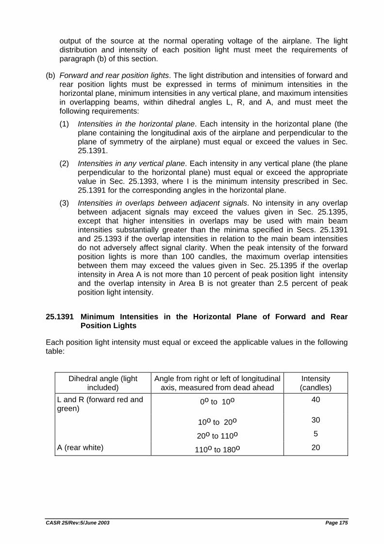
output of the source at the normal operating voltage of the airplane. The light distribution and intensity of each position light must meet the requirements of paragraph (b) of this section.
(b) Forward and rear position lights. The light distribution and intensities of forward and rear position lights must be expressed in terms of minimum intensities in the horizontal plane, minimum intensities in any vertical plane, and maximum intensities in overlapping beams, within dihedral angles L, R, and A, and must meet the following requirements: (1) Intensities in the horizontal plane. Each intensity in the horizontal plane (the
plane containing the longitudinal axis of the airplane and perpendicular to the plane of symmetry of the airplane) must equal or exceed the values in Sec. 25.1391.
(2) Intensities in any vertical plane. Each intensity in any vertical plane (the plane perpendicular to the horizontal plane) must equal or exceed the appropriate value in Sec. 25.1393, where I is the minimum intensity prescribed in Sec. 25.1391 for the corresponding angles in the horizontal plane.
(3) Intensities in overlaps between adjacent signals. No intensity in any overlap between adjacent signals may exceed the values given in Sec. 25.1395, except that higher intensities in overlaps may be used with main beam intensities substantially greater than the minima specified in Secs. 25.1391 and 25.1393 if the overlap intensities in relation to the main beam intensities do not adversely affect signal clarity. When the peak intensity of the forward position lights is more than 100 candles, the maximum overlap intensities between them may exceed the values given in Sec. 25.1395 if the overlap intensity in Area A is not more than 10 percent of peak position light intensity and the overlap intensity in Area B is not greater than 2.5 percent of peak position light intensity.
25.1391 Minimum Intensities in the Horizontal Plane of Forward and Rear Position Lights
Each position light intensity must equal or exceed the applicable values in the following table:
Dihedral angle (light
included) Angle from right or left of longitudinal
axis, measured from dead ahead Intensity (candles)
L and R (forward red and green)
0o to 10o 40
10o to 20o 30
20o to 110o 5
A (rear white) 110o to 180o 20
CASR 25/Rev:5/June 2003 Page 175
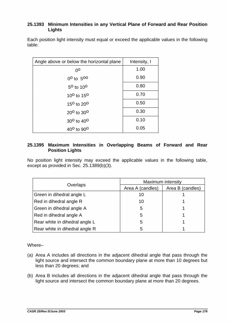
25.1393 Minimum Intensities in any Vertical Plane of Forward and Rear Position Lights
Each position light intensity must equal or exceed the applicable values in the following table:
Angle above or below the horizontal plane Intensity, I
0o 1.00
0o to 5oo 0.90
5o to 10o 0.80
10o to 15o 0.70
15o to 20o 0.50
20o to 30o 0.30
30o to 40o 0.10
40o to 90o 0.05
25.1395 Maximum Intensities in Overlapping Beams of Forward and Rear Position Lights
No position light intensity may exceed the applicable values in the following table, except as provided in Sec. 25.1389(b)(3).
Maximum intensity Overlaps
Area A (candles) Area B (candles) Green in dihedral angle L 10 1 Red in dihedral angle R 10 1 Green in dihedral angle A 5 1 Red in dihedral angle A 5 1 Rear white in dihedral angle L 5 1 Rear white in dihedral angle R 5 1
Where–
(a) Area A includes all directions in the adjacent dihedral angle that pass through the light source and intersect the common boundary plane at more than 10 degrees but less than 20 degrees; and
(b) Area B includes all directions in the adjacent dihedral angle that pass through the light source and intersect the common boundary plane at more than 20 degrees.
CASR 25/Rev:5/June 2003 Page 176
25.1397 Color Specifications
Each position light color must have the applicable International Commission on Illumination chromaticity coordinates as follows:
(a) Aviation red– "y" is not greater than 0.335; and "z" is not greater than 0.002. (b) Aviation green– "x" is not greater than 0.440– 0.320 y ; "x" is not greater than y– 0.170; and "y" is not less than 0.390– 0.170 x. (c) Aviation white– "x" is not less than 0.300 and not greater than 0.540; "y" is not less than "x– 0.040" or "y0– 0.010", whichever is the smaller; and
"y" is not greater than "x + 0.020" nor "0.636– 0.400 x"; Where "y0" is the "y" coordinate of the Planckian radiator for the value of "x" considered.
25.1399 Riding Light
(a) Each riding (anchor) light required for a seaplane or amphibian must be installed so that it can– (1) Show a white light for at least 2 nautical miles at night under clear atmospheric
conditions; and (2) Show the maximum unbroken light practicable when the airplane is moored or
drifting on the water.
(b) Externally hung lights may be used.
25.1401 Anticollision Light System
(a) General. The airplane must have an anticollision light system that– (1) Consists of one or more approved anticollision lights located so that their light
will not impair the crew's vision or detract from the conspicuity of the position lights; and
(2) Meets the requirements of paragraphs (b) through (f) of this section.
(b) Field of coverage. The system must consist of enough lights to illuminate the vital areas around the airplane considering the physical configuration and flight characteristics of the airplane. The field of coverage must extend in each direction within at least 75 degrees above and 75 degrees below the horizontal plane of the airplane, except that a solid angle or angles of obstructed visibility totaling not more than 0.03 steradians is allowable within a solid angle equal to 0.15 steradians centered about the longitudinal axis in the rearward direction.
CASR 25/Rev:5/June 2003 Page 177
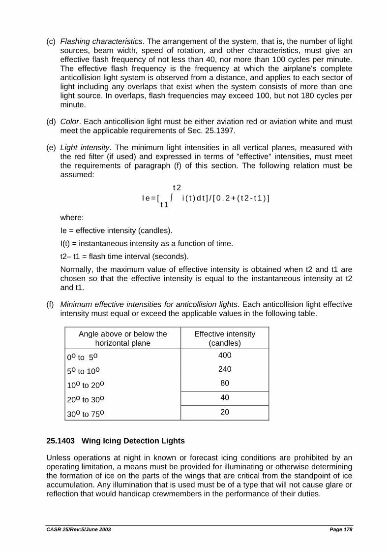
(c) Flashing characteristics. The arrangement of the system, that is, the number of light sources, beam width, speed of rotation, and other characteristics, must give an effective flash frequency of not less than 40, nor more than 100 cycles per minute. The effective flash frequency is the frequency at which the airplane's complete anticollision light system is observed from a distance, and applies to each sector of light including any overlaps that exist when the system consists of more than one light source. In overlaps, flash frequencies may exceed 100, but not 180 cycles per minute.
(d) Color. Each anticollision light must be either aviation red or aviation white and must meet the applicable requirements of Sec. 25.1397.
(e) Light intensity. The minimum light intensities in all vertical planes, measured with the red filter (if used) and expressed in terms of "effective" intensities, must meet the requirements of paragraph (f) of this section. The following relation must be assumed:
I e = [t 1
∫t 2
i ( t ) d t ] / [ 0 . 2 + ( t 2 - t 1 ) ]
where: Ie = effective intensity (candles). I(t) = instantaneous intensity as a function of time. t2– t1 = flash time interval (seconds). Normally, the maximum value of effective intensity is obtained when t2 and t1 are chosen so that the effective intensity is equal to the instantaneous intensity at t2 and t1.
(f) Minimum effective intensities for anticollision lights. Each anticollision light effective intensity must equal or exceed the applicable values in the following table.
Angle above or below the
horizontal plane Effective intensity
(candles)
0o to 5o 400
5o to 10o 240
10o to 20o 80
20o to 30o 40
30o to 75o 20
25.1403 Wing Icing Detection Lights
Unless operations at night in known or forecast icing conditions are prohibited by an operating limitation, a means must be provided for illuminating or otherwise determining the formation of ice on the parts of the wings that are critical from the standpoint of ice accumulation. Any illumination that is used must be of a type that will not cause glare or reflection that would handicap crewmembers in the performance of their duties.
CASR 25/Rev:5/June 2003 Page 178
SAFETY EQUIPMENT
25.1411 General
(a) Accessibility. Required safety equipment to be used by the crew in an emergency must be readily accessible.
(b) Stowage provisions. Stowage provisions for required emergency equipment must be furnished and must– (1) Be arranged so that the equipment is directly accessible and its location is
obvious; and (2) Protect the safety equipment from inadvertent damage.
(c) Emergency exit descent device. The stowage provisions for the emergency exit descent device required by Sec. 25.809(f) must be at the exits for which they are intended.
(d) Life rafts. (1) The stowage provisions for the life rafts described in Sec. 25.1415 must
accommodate enough rafts for the maximum number of occupants for which certification for ditching is requested.
(2) Life rafts must be stowed near exits through which the rafts can be launched during an unplanned ditching.
(3) Rafts automatically or remotely released outside the airplane must be attached to the airplane by means of the static line prescribed in Sec. 25.1415.
(4) The stowage provisions for each portable life raft must allow rapid detachment and removal of the raft for use at other than the intended exits.
(e) Long range signaling device. The stowage provisions for the long range signaling device required by Sec. 25.1415 must be near an exit available during an unplanned ditching.
(f) Life preserver stowage provisions. The stowage provisions for life preservers described in Sec. 25.1415 must accommodate one life preserver for each occupant for which certification for ditching is requested. Each life preserver must be within easy reach of each seated occupant.
(g) Life line stowage provisions. If certification for ditching under Sec. 25.801 is requested, there must be provisions to store life lines. These provisions must - (1) Allow one life line to be attached to each side of the fuselage; and (2) Be arranged to allow the life lines to be used to enable the occupants to stay
on the wing after ditching. This requirement is not applicable to airplanes having no over-wing ditching exits.
[Rev. 25–1, KM.7 Year 1996, 15 Feb. 1996; ref. FAR Amdt. 25–80; Rev. 25-3, SKEP/145/VI/99, 29 Jun. 1999, ref. DGCA Policy Letter No. 5, dated 30th April 1998]
CASR 25/Rev:5/June 2003 Page 179
25.1415 Ditching Equipment
(a) Ditching equipment used in airplanes to be certificated for ditching under Sec. 25.801, and required by the operating rules, must meet the requirements of this section.
(b) Each life raft and each life preserver must be approved. In addition− (1) Unless excess rafts of enough capacity are provided, the buoyancy and
seating capacity beyond the rated capacity of the rafts must accommodate all occupants of the airplane in the event of a loss of one raft of the largest rated capacity; and
(2) Each raft must have a trailing line, and must have a static line designed to hold the raft near the airplane but to release it if the airplane becomes totally submerged.
(c) Approved survival equipment must be attached to each life raft.
(d) There must be an approved survival type emergency locator transmitter for use in one life raft.
(e) For airplanes not certificated for ditching under Sec. 25.801 and not having approved life preservers, there must be an approved flotation means for each occupant. This means must be within easy reach of each seated occupant and must be readily removable from the airplane. [Rev. 25-2, SKEP/199/XII/96, 26 Dec. 1996, ref. FAR Amdt. 25-82]
25.1419 Ice Protection
If certification with ice protection provisions is desired, the airplane must be able to be safely operated in the continuous maximum and intermittent maximum icing conditions of appendix C. To establish that the airplane can operate within the continuous maximum and intermittent maximum conditions of appendix C:
(a) An analysis must be performed to establish that the ice protection for the various components of the airplane is adequate, taking into account the various airplane operational configurations; and
(b) To verify the ice protection analysis, to check for icing anomalies, and to demonstrate that the ice protection system and its components are effective, the airplane or its components must be flight tested in the various operational configurations, in measured natural atmospheric icing conditions and, as found necessary, by one or more of the following means: (1) Laboratory dry air or simulated icing test, or a combination of both, of the
components or models of the components. (2) Flight dry air tests of the ice protection system as a whole, or of its individual
components. (3) Flight tests of the airplane or its components in measured simulated icing
conditions.
CASR 25/Rev:5/June 2003 Page 180
(c) Caution information, such as an amber caution light or equivalent, must be provided to alert the flightcrew when the anti–ice or deice system is not functioning normally.
(d) For turbine engine powered airplanes, the ice protection provisions of this section are considered to be applicable primarily to the airframe. For the powerplant installation, certain additional provisions of subpart E of this attachment may be found applicable.
25.1421 Megaphones
If a megaphone is installed, a restraining means must be provided that is capable of restraining the megaphone when it is subjected to the ultimate inertia forces specified in Sec. 25.561(b)(3).
25.1423 Public Address System
A public address system required by this chapter must–
(a) Be powerable when the aircraft is in flight or stopped on the ground, after the shutdown or failure of all engines and auxiliary power units, or the disconnection or failure of all power sources dependent on their continued operation, for– (1) A time duration of at least 10 minutes, including an aggregate time duration of
at least 5 minutes of announcements made by flight and cabin crewmembers, considering all other loads which may remain powered by the same source when all other power sources are inoperative; and
(2) An additional time duration in its standby state appropriate or required for any other loads that are powered by the same source and that are essential to safety of flight or required during emergency conditions.
(b) Be capable of operation within 10 seconds by a flight attendant at those stations in the passenger compartment from which the system is accessible.
(c) Be intelligible at all passenger seats, lavatories, and flight attendant seats and work stations.
(d) Be designed so that no unused, unstowed microphone will render the system inoperative.
(e) Be capable of functioning independently of any required crewmember interphone system.
(f) Be accessible for immediate use from each of two flight crewmember stations in the pilot compartment.
(g) For each required floor-level passenger emergency exit which has an adjacent flight attendant seat, have a microphone which is readily accessible to the seated flight attendant, except that one microphone may serve more than one exit, provided the proximity of the exits allows unassisted verbal communication between seated flight attendants. [Rev. 25–1, KM.7 Year 1996, 15 Feb. 1996; ref. FAR Amdt. 25–79]
CASR 25/Rev:5/June 2003 Page 181
MISCELLANEOUS EQUIPMENT
25.1431 Electronic Equipment
(a) In showing compliance with Sec. 25.1309 (a) and (b) with respect to radio and electronic equipment and their installations, critical environmental conditions must be considered.
(b) Radio and electronic equipment must be supplied with power under the requirements of Sec. 25.1355(c).
(c) Radio and electronic equipment, controls, and wiring must be installed so that operation of any one unit or system of units will not adversely affect the simultaneous operation of any other radio or electronic unit, or system of units, required by this Decree.
25.1433 Vacuum Systems
There must be means, in addition to the normal pressure relief, to automatically relieve the pressure in the discharge lines from the vacuum air pump when the delivery temperature of the air becomes unsafe.
25.1435 Hydraulic Systems
(a) Design. (1) Each element of the hydraulic system must be designed to withstand, without
deformation that would prevent it from performing its intended function, the design operating pressure loads in combination with limit structural loads which may be imposed.
(2) Each element of the hydraulic system must be able to withstand, without rupture, the design operating pressure loads multiplied by a factor 1.5 in combination with ultimate structural loads that can reasonably occur simultaneously. Design operating pressure is maximum normal operating pressure, excluding transient pressure.
(b) Tests and analysis. (1) A complete hydraulic system must be static tested to show that it can
withstand 1.5 times the design operating pressure without a deformation of any part of the system that would prevent it from performing its intended function. Clearance between structural members and hydraulic system elements must be adequate and there must be no permanent detrimental deformation. For the purpose of this test, the pressure relief valve may be made inoperable to permit application of the required pressure.
(2) Compliance with Sec. 25.1309 for hydraulic systems must be shown by functional tests, endurance tests, and analyses. The entire system, or appropriate subsystems, must be tested in an airplane or in a mockup installation to determine proper performance and proper relation to other aircraft systems. The functional tests must include simulation of hydraulic system failure conditions. Endurance tests must simulate the repeated
CASR 25/Rev:5/June 2003 Page 182
complete flights that could be expected to occur in service. Elements which failed during the tests must be modified in order to have the design deficiency corrected and, where necessary, must be sufficiently retested. Simulation of operating and environmental conditions must be completed on elements and appropriate portions of the hydraulic system to the extent necessary to evaluate the environmental effects. Compliance with Sec. 25.1309 must take into account the following: (i) Static and dynamic loads including flight, ground, pilot, hydrostatic,
inertial and thermally induced loads, and combinations thereof. (ii) Motion, vibration, pressure transients, and fatigue. (iii) Abrasion, corrosion, and erosion. (iv) Fluid and material compatibility. (v) Leakage and wear.
(c) Fire protection. Each hydraulic system using flammable hydraulic fluid must meet the applicable requirements of Secs. 25.863, 25.1183, 25.1185, and 25.1189.
25.1438 Pressurization and Pneumatic Systems
(a) Pressurization system elements must be burst pressure tested to 2.0 times, and proof pressure tested to 1.5 times, the maximum normal operating pressure.
(b) Pneumatic system elements must be burst pressure tested to 3.0 times, and proof pressure tested to 1.5 times, the maximum normal operating pressure.
(c) An analysis, or a combination of analysis and test, may be substituted for any test required by paragraph (a) or (b) of this section if the Director General finds it equivalent to the required test.
25.1439 Protective Breathing Equipment
(a) If there is a class A, B, or E cargo compartment, protective breathing equipment must be installed for the use of appropriate crewmembers. In addition, protective breathing equipment must be installed in each isolated separate compartment in the airplane, including upper and lower lobe galleys, in which crewmember occupancy is permitted during flight for the maximum number of crewmembers expected to be in the area during any operation.
(b) For protective breathing equipment required by paragraph (a) of this section or by any operating rule, the following apply: (1) The equipment must be designed to protect the flight crew from smoke,
carbon dioxide, and other harmful gases while on flight deck duty and while combating fires in cargo compartments.
(2) The equipment must include– (i) Masks covering the eyes, nose, and mouth; or (ii) Masks covering the nose and mouth, plus accessory equipment to
cover the eyes. (3) The equipment, while in use, must allow the flight crew to use the radio
equipment and to communicate with each other, while at their assigned duty stations.
CASR 25/Rev:5/June 2003 Page 183
(4) The part of the equipment protecting the eyes may not cause any appreciable adverse effect on vision and must allow corrective glasses to be worn.
(5) The equipment must supply protective oxygen of 15 minutes duration per crewmember at a pressure altitude of 8,000 feet with a respiratory minute volume of 30 liters per minute BTPD. If a demand oxygen system is used, a supply of 300 liters of free oxygen at 70o F. and 760 mm. Hg. pressure is considered to be of 15 minute duration at the prescribed altitude and minute volume. If a continuous flow protective breathing system is used (including a mask with a standard rebreather bag) a flow rate of 60 liters per minute at 8,000 feet (45 liters per minute at sea level) and a supply of 600 liters of free oxygen at 70o F. and 760 mm. Hg. pressure is considered to be of 15 minute duration at the prescribed altitude and minute volume. BTPD refers to body temperature conditions (that is, 37o C., at ambient pressure, dry).
(6) The equipment must meet the requirements of paragraphs (b) and (c) of Sec. 25.1441.
25.1441 Oxygen Equipment and Supply
(a) If certification with supplemental oxygen equipment is requested, the equipment must meet the requirements of this section and Secs. 25.1443 through 25.1453.
(b) The oxygen system must be free from hazards in itself, in its method of operation, and in its effect upon other components.
(c) There must be a means to allow the crew to readily determine, during flight, the quantity of oxygen available in each source of supply.
(d) The oxygen flow rate and the oxygen equipment for airplanes for which certification for operation above 40,000 feet is requested must be approved.
25.1443 Minimum Mass Flow of Supplemental Oxygen
(a) If continuous flow equipment is installed for use by flight crewmembers, the minimum mass flow of supplemental oxygen required for each crewmember may not be less than the flow required to maintain, during inspiration, a mean tracheal oxygen partial pressure of 149 mm. Hg. when breathing 15 liters per minute, BTPS, and with a maximum tidal volume of 700 cc. with a constant time interval between respirations.
(b) If demand equipment is installed for use by flight crewmembers, the minimum mass flow of supplemental oxygen required for each crewmember may not be less than the flow required to maintain, during inspiration, a mean tracheal oxygen partial pressure of 122 mm. Hg., up to and including a cabin pressure altitude of 35,000 feet, and 95 percent oxygen between cabin pressure altitudes of 35,000 and 40,000 feet, when breathing 20 liters per minute BTPS. In addition, there must be means to allow the crew to use undiluted oxygen at their discretion.
(c) For passengers and cabin attendants, the minimum mass flow of supplemental oxygen required for each person at various cabin pressure altitudes may not be less than the flow required to maintain, during inspiration and while using the oxygen
CASR 25/Rev:5/June 2003 Page 184
equipment (including masks) provided, the following mean tracheal oxygen partial pressures: (1) At cabin pressure altitudes above 10,000 feet up to and including 18,500 feet,
a mean tracheal oxygen partial pressure of 100 mm. Hg. when breathing 15 liters per minute, BTPS, and with a tidal volume of 700 cc. with a constant time interval between respirations.
(2) At cabin pressure altitudes above 18,500 feet up to and including 40,000 feet, a mean tracheal oxygen partial pressure of 83.8 mm. Hg. when breathing 30 liters per minute, BTPS, and with a tidal volume of 1,100 cc. with a constant time interval between respirations.
(d) If first aid oxygen equipment is installed, the minimum mass flow of oxygen to each user may not be less than four liters per minute, STPD. However, there may be a means to decrease this flow to not less than two liters per minute, STPD, at any cabin altitude. The quantity of oxygen required is based upon an average flow rate of three liters per minute per person for whom first aid oxygen is required.
(e) If portable oxygen equipment is installed for use by crewmembers, the minimum mass flow of supplemental oxygen is the same as specified in paragraph (a) or (b) of this section, whichever is applicable.
25.1445 Equipment Standards for the Oxygen Distributing System
(a) When oxygen is supplied to both crew and passengers, the distribution system must be designed for either– (1) A source of supply for the flight crew on duty and a separate source for the
passengers and other crewmembers; or (2) A common source of supply with means to separately reserve the minimum
supply required by the flight crew on duty.
(b) Portable walk around oxygen units of the continuous flow, diluter demand, and straight demand kinds may be used to meet the crew or passenger breathing requirements.
25.1447 Equipment Standards for Oxygen Dispensing Units
If oxygen dispensing units are installed, the following apply:
(a) There must be an individual dispensing unit for each occupant for whom supplemental oxygen is to be supplied. Units must be designed to cover the nose and mouth and must be equipped with a suitable means to retain the unit in position on the face. Flight crew masks for supplemental oxygen must have provisions for the use of communication equipment.
(b) If certification for operation up to and including 25,000 feet is requested, an oxygen supply terminal and unit of oxygen dispensing equipment for the immediate use of oxygen by each crewmember must be within easy reach of that crew member. For any other occupants, the supply terminals and dispensing equipment must be located to allow the use of oxygen as required by the operating rules.
CASR 25/Rev:5/June 2003 Page 185
(c) If certification for operation above 25,000 feet is requested, there must be oxygen dispensing equipment meeting the following requirements: (1) There must be an oxygen dispensing unit connected to oxygen supply
terminals immediately available to each occupant, wherever seated, and at least two oxygen dispensing units connected to oxygen terminals in each lavatory. The total number of dispensing units and outlets in the cabin must exceed the number of seats by at least 10 percent. The extra units must be as uniformly distributed throughout the cabin as practicable. If certification for operation above 30,000 feet is requested, the dispensing units providing the required oxygen flow must be automatically presented to the occupants before the cabin pressure altitude exceeds 15,000 feet. The crew must be provided with a manual means of making the dispensing units immediately available in the event of failure of the automatic system.
(2) Each flight crewmember on flight deck duty must be provided with a quick-donning type oxygen dispensing unit connected to an oxygen supply terminal. This dispensing unit must be immediately available to the flight crewmember when seated at his station, and installed so that it: (i) Can be placed on the face from its ready position, properly secured,
sealed, and supplying oxygen upon demand, with one hand, within five seconds and without disturbing eyeglasses or causing delay in proceeding with emergency duties; and
(ii) Allows, while in place, the performance of normal communication functions.
(3) The oxygen dispensing equipment for the flight crewmembers must be: (i) The diluter demand or pressure demand (pressure demand mask with a
diluter demand pressure breathing regulator) type, or other approved oxygen equipment shown to provide the same degree of protection, for airplanes to be operated above 25,000 feet.
(ii) The pressure demand (pressure demand mask with a diluter demand pressure breathing regulator) type with mask-mounted regulator, or other approved oxygen equipment shown to provide the same degree of protection, for airplanes operated at altitudes where decompressions that are not extremely improbable may expose the flightcrew to cabin pressure altitudes in excess of 34,000 feet.
(4) Portable oxygen equipment must be immediately available for each cabin attendant.
[Rev. 25-2, SKEP/199/XII/96, 26 Dec. 1996, ref. FAR Amdt. 25-87]
25.1449 Means for Determining Use of Oxygen
There must be a means to allow the crew to determine whether oxygen is being delivered to the dispensing equipment.
25.1450 Chemical Oxygen Generators
(a) For the purpose of this section, a chemical oxygen generator is defined as a device which produces oxygen by chemical reaction.
CASR 25/Rev:5/June 2003 Page 186
(b) Each chemical oxygen generator must be designed and installed in accordance with the following requirements: (1) Surface temperature developed by the generator during operation may not
create a hazard to the airplane or to its occupants. (2) Means must be provided to relieve any internal pressure that may be
hazardous.
(c) In addition to meeting the requirements in paragraph (b) of this section, each portable chemical oxygen generator that is capable of sustained operation by successive replacement of a generator element must be placarded to show– (1) The rate of oxygen flow, in liters per minute; (2) The duration of oxygen flow, in minutes, for the replaceable generator
element; and (3) A warning that the replaceable generator element may be hot, unless the
element construction is such that the surface temperature cannot exceed 100 degrees F.
25.1453 Protection of Oxygen Equipment from Rupture
Oxygen pressure tanks, and lines between tanks and the shutoff means, must be–
(a) Protected from unsafe temperatures; and
(b) Located where the probability and hazards of rupture in a crash landing are minimized.
25.1455 Draining of Fluids Subject to Freezing
If fluids subject to freezing may be drained overboard in flight or during ground operation, the drains must be designed and located to prevent the formation of hazardous quantities of ice on the airplane as a result of the drainage.
25.1457 Cockpit Voice Recorders
(a) Each cockpit voice recorder if required by the operating rules must be approved and must be installed so that it will record the following: (1) Voice communications transmitted from or received in the airplane by radio. (2) Voice communications of flight crewmembers on the flight deck. (3) Voice communications of flight crewmembers on the flight deck, using the
airplane's interphone system. (4) Voice or audio signals identifying navigation or approach aids introduced into a
headset or speaker. (5) Voice communications of flight crewmembers using the passenger
loudspeaker system, if there is such a system and if the fourth channel is available in accordance with the requirements of paragraph (c)(4)(ii) of this section.
CASR 25/Rev:5/June 2003 Page 187
(b) The recording requirements of paragraph (a)(2) of this section must be met by installing a cockpit mounted area microphone, located in the best position for recording voice communications originating at the first and second pilot stations and voice communications of other crewmembers on the flight deck when directed to those stations. The microphone must be so located and, if necessary, the preamplifiers and filters of the recorder must be so adjusted or supplemented, that the intelligibility of the recorded communications is as high as practicable when recorded under flight cockpit noise conditions and played back. Repeated aural or visual playback of the record may be used in evaluating intelligibility.
(c) Each cockpit voice recorder must be installed so that the part of the communication or audio signals specified in paragraph (a) of this section obtained from each of the following sources is recorded on a separate channel: (1) For the first channel, from each boom, mask, or hand held microphone,
headset, or speaker used at the first pilot station. (2) For the second channel from each boom, mask, or hand held microphone,
headset, or speaker used at the second pilot station. (3) For the third channel–from the cockpit mounted area microphone. (4) For the fourth channel, from–
(i) Each boom, mask, or hand held microphone, headset, or speaker used at the station for the third and fourth crew members; or
(ii) If the stations specified in paragraph (c)(4)(i) of this section are not required or if the signal at such a station is picked up by another channel, each microphone on the flight deck that is used with the passenger loudspeaker system, if its signals are not picked up by another channel.
(5) As far as is practicable all sounds received by the microphone listed in paragraphs (c)(1), (2), and (4) of this section must be recorded without interruption irrespective of the position of the interphone/transmitter key switch. The design shall ensure that sidetone for the flight crew is produced only when the interphone, public address system, or radio transmitters are in use.
(d) Each cockpit voice recorder must be installed so that– (1) It receives its electric power from the bus that provides the maximum reliability
for operation of the cockpit voice recorder without jeopardizing service to essential or emergency loads;
(2) There is an automatic means to simultaneously stop the recorder and prevent each erasure feature from functioning, within 10 minutes after crash impact; and
(3) There is an aural or visual means for preflight checking of the recorder for proper operation.
(e) The record container must be located and mounted to minimize the probability of rupture of the container as a result of crash impact and consequent heat damage to the record from fire. In meeting this requirement, the record container must be as far aft as practicable, but may not be where aft mounted engines may crush the container during impact. However, it need not be outside of the pressurized compartment.
CASR 25/Rev:5/June 2003 Page 188
(f) If the cockpit voice recorder has a bulk erasure device, the installation must be designed to minimize the probability of inadvertent operation and actuation of the device during crash impact.
(g) Each recorder container must– (1) Be either bright orange or bright yellow; (2) Have reflective tape affixed to its external surface to facilitate its location under
water; and (3) Have an underwater locating device, when required by the operating rules, on
or adjacent to the container which is secured in such manner that they are not likely to be separated during crash impact.
25.1459 Flight Recorders
(a) Each flight recorder if required by the operating rules must be installed so that– (1) It is supplied with airspeed, altitude, and directional data obtained from
sources that meet the accuracy requirements of Secs. 25.1323, 25.1325, and 25.1327, as appropriate;
(2) The vertical acceleration sensor is rigidly attached, and located longitudinally either within the approved center of gravity limits of the airplane, or at a distance forward or aft of these limits that does not exceed 25 percent of the airplane's mean aerodynamic chord;
(3) It receives its electrical power from the bus that provides the maximum reliability for operation of the flight recorder without jeopardizing service to essential or emergency loads;
(4) There is an aural or visual means for preflight checking of the recorder for proper recording of data in the storage medium.
(5) Except for recorders powered solely by the engine driven electrical generator system, there is an automatic means to simultaneously stop a recorder that has a data erasure feature and prevent each erasure feature from functioning, within 10 minutes after crash impact; and
(6) There is a means to record data from which the time of each radio transmission either to or from ATC can be determined.
(b) Each nonejectable record container must be located and mounted so as to minimize the probability of container rupture resulting from crash impact and subsequent damage to the record from fire. In meeting this requirement the record container must be located as far aft as practicable, but need not be aft of the pressurized compartment, and may not be where aft mounted engines may crush the container upon impact.
(c) A correlation must be established between the flight recorder readings of airspeed, altitude, and heading and the corresponding readings (taking into account correction factors) of the first pilot's instruments. The correlation must cover the airspeed range over which the airplane is to be operated, the range of altitude to which the airplane is limited, and 360 degrees of heading. Correlation may be established on the ground as appropriate.
CASR 25/Rev:5/June 2003 Page 189
(d) Each recorder container must– (1) Be either bright orange or bright yellow; (2) Have reflective tape affixed to its external surface to facilitate its location under
water; and (3) Have an underwater locating device, when required by the operating rules, on
or adjacent to the container which is secured in such a manner that they are not likely to be separated during crash impact.
(e) Any novel or unique design or operational characteristics of the aircraft shall be evaluated to determine if any dedicated parameters must be recorded on flight recorders in addition to or in place of existing requirements.
25.1461 Equipment Containing High Energy Rotors
(a) Equipment containing high energy rotors must meet paragraph (b), (c), or (d) of this section.
(b) High energy rotors contained in equipment must be able to withstand damage caused by malfunctions, vibration, abnormal speeds, and abnormal temperatures. In addition– (1) Auxiliary rotor cases must be able to contain damage caused by the failure of
high energy rotor blades; and (2) Equipment control devices, systems, and instrumentation must reasonably
ensure that no operating limitations affecting the integrity of high energy rotors will be exceeded in service.
(c) It must be shown by test that equipment containing high energy rotors can contain any failure of a high energy rotor that occurs at the highest speed obtainable with the normal speed control devices inoperative.
(d) Equipment containing high energy rotors must be located where rotor failure will neither endanger the occupants nor adversely affect continued safe flight.
CASR 25/Rev:5/June 2003 Page 190
SUBPART G - OPERATING LIMITATIONS AND INFORMATION
25.1501 General
(a) Each operating limitation specified in Secs. 25.1503 through 25.1533 and other limitations and information necessary for safe operation must be established.
(b) The operating limitations and other information necessary for safe operation must be made available to the crewmembers as prescribed in Secs. 25.1541 through 25.1587.
OPERATING LIMITATIONS
25.1503 Airspeed Limitations: General
When airspeed limitations are a function of weight, weight distribution, altitude, or Mach number, limitations corresponding to each critical combination of these factors must be established.
25.1505 Maximum Operating Limit Speed
The maximum operating limit speed (VMO/MMO airspeed or Mach Number, whichever is critical at a particular altitude) is a speed that may not be deliberately exceeded in any regime of flight (climb, cruise, or descent), unless a higher speed is authorized for flight test or pilot training operations. VMO/MMO must be established so that it is not greater than the design cruising speed VC and so that it is sufficiently below VD/MD or VDF/MDF, to make it highly improbable that the latter speeds will be inadvertently exceeded in operations. The speed margin between VMO/MMO and VD/MD or VDF/MDF may not be less than that determined under Sec. 25.335(b) or found necessary during the flight tests conducted under Sec. 25.253.
25.1507 Maneuvering Speed
The maneuvering speed must be established so that it does not exceed the design maneuvering speed VA determined under Sec. 25.335(c).
25.1511 Flap Extended Speed
The established flap extended speed VFE must be established so that it does not exceed the design flap speed VF chosen under Secs. 25.335(e) and 25.345, for the corresponding flap positions and engine powers.
25.1513 Minimum Control Speed
The minimum control speed VMC determined under Sec. 25.149 must be established as an operating limitation.
CASR 25/Rev:5/June 2003 Page 191
25.1515 Landing Gear Speeds
(a) The established landing gear operating speed or speeds, VLO, may not exceed the speed at which it is safe both to extend and to retract the landing gear, as determined under Sec. 25.729 or by flight characteristics. If the extension speed is not the same as the retraction speed, the two speeds must be designated as VLO(EXT) and VLO(RET), respectively.
(b) The established landing gear extended speed VLE may not exceed the speed at which it is safe to fly with the landing gear secured in the fully extended position, and that determined under Sec. 25.729.
25.1517 Rough Air Speed, VRA
A rough air speed, VRA, for use as the recommended turbulence penetration airspeed in §25.1585(a)(8), must be established, which–
(a) Is not greater than the design airspeed for maximum gust intensity, selected for VB; and
(b) Is not less than the minimum value of VB specified in § 25.335(d); and
(c) Is sufficiently less than VMO to ensure that likely speed variation during rough air encounters will not cause the overspeed warning to operate too frequently. In the absence of a rational investigation substantiating the use of other values, VRA must be less than VMO – 35 knots (TAS).
[Rev. 25-2, SKEP/199/XII/96, 26 Dec. 1996, ref. FAR Amdt. 25-86]
25.1519 Weight, Center of Gravity, and Weight Distribution
The airplane weight, center of gravity, and weight distribution limitations determined under Secs. 25.23 through 25.27 must be established as operating limitations.
25.1521 Powerplant Limitations
(a) General. The powerplant limitations prescribed in this section must be established so that they do not exceed the corresponding limits for which the engines or propellers are type certificated and do not exceed the values on which compliance with any other requirement of this attachment is based.
(b) Reciprocating engine installations. Operating limitations relating to the following must be established for reciprocating engine installations: (1) Horsepower or torque, rpm, manifold pressure, and time at critical pressure
altitude and sea level pressure altitude for– (i) Maximum continuous power (relating to unsupercharged operation or to
operation in each supercharger mode as applicable); and (ii) Takeoff power (relating to unsupercharged operation or to operation in
each supercharge mode as applicable). (2) Fuel grade or specification.
CASR 25/Rev:5/June 2003 Page 192
(3) Cylinder head and oil temperatures. (4) Any other parameter for which a limitation has been established as part of the
engine type certificate expect that a limitation need not be established for a parameter that cannot be exceeded during normal operation due to the design of the installation or to another established limitation.
(c) Turbine engine installations. Operating limitations relating to the following must be established for turbine engine installations: (1) Horsepower, torque or thrust, rpm, gas temperature, and time for–
(i) Maximum continuous power or thrust (relating to augmented or unaugmented operation as applicable).
(ii) Takeoff power or thrust (relating to augmented or unaugmented operation as applicable).
(2) Fuel designation or specification. (3) Any other parameter for which a limitation has been established as part of the
engine type certificate except that a limitation need not be established for a parameter that cannot be exceeded during normal operation due to the design of the installation or to another established limitation.
(d) Ambient temperature. An ambient temperature limitation (including limitations for winterization installations, if applicable) must be established as the maximum ambient atmospheric temperature established in accordance with Sec. 25.1043(b).
25.1522 Auxiliary Power Unit Limitations
If an auxiliary power unit is installed in the airplane, limitations established for the auxiliary power unit, including categories of operation, must be specified as operating limitations for the airplane.
25.1523 Minimum Flight Crew
The minimum flight crew must be established so that it is sufficient for safe operation, considering–
(a) The workload on individual crewmembers;
(b) The accessibility and ease of operation of necessary controls by the appropriate crewmember; and
(c) The kind of operation authorized under Sec. 25.1525.
The criteria used in making the determinations required by this section are set forth in Appendix D.
25.1525 Kinds of Operation
The kinds of operation to which the airplane is limited are established by the category in which it is eligible for certification and by the installed equipment.
CASR 25/Rev:5/June 2003 Page 193
25.1527 Maximum Operating Altitude
The maximum altitude up to which operation is allowed, as limited by flight, structural, powerplant, functional, or equipment characteristics, must be established.
25.1529 Instructions for Continued Airworthiness
The applicant must prepare Instructions for Continued Airworthiness in accordance with Appendix H to this attachment that are acceptable to the Director General. The instructions may be incomplete at type certification if a program exists to ensure their completion prior to delivery of the first airplane or issuance of a standard certificate of airworthiness, whichever occurs later.
25.1531 Maneuvering Flight Load Factors
Load factor limitations, not exceeding the positive limit load factors determined from the maneuvering diagram in Sec. 25.333(b), must be established.
25.1533 Additional Operating Limitations
(a) Additional operating limitations must be established as follows: (1) The maximum takeoff weights must be established as the weights at which
compliance is shown with the applicable provisions of this attachment (including the takeoff climb provisions of Sec. 25.121(a) through (c), for altitudes and ambient temperatures).
(2) The maximum landing weights must be established as the weights at which compliance is shown with the applicable provisions of this attachment (including the landing and approach climb provisions of Secs. 25.119 and 25.121(d) for altitudes and ambient temperatures).
(3) The minimum takeoff distances must be established as the distances at which compliance is shown with the applicable provisions of this attachment (including the provisions of Secs. 25.103 and 25.113, for weights, altitudes, temperatures, wind components, and runway gradients).
(b) The extremes for variable factors (such as altitude, temperature, wind, and runway gradients) are those at which compliance with the applicable provisions of this attachment is shown.
MARKINGS AND PLACARDS
25.1541 General
(a) The airplane must contain– (1) The specified markings and placards; and (2) Any additional information, instrument markings, and placards required for the
safe operation if there are unusual design, operating, or handling characteristics.
CASR 25/Rev:5/June 2003 Page 194
(b) Each marking and placard prescribed in paragraph (a) of this section– (1) Must be displayed in a conspicuous place; and (2) May not be easily erased, disfigured, or obscured.
25.1543 Instrument Markings: General
For each instrument–
(a) When markings are on the cover glass of the instrument, there must be means to maintain the correct alignment of the glass cover with the face of the dial; and
(b) Each instrument marking must be clearly visible to the appropriate crewmember.
25.1545 Airspeed Limitation Information
The airspeed limitations required by Sec. 25.1583 (a) must be easily read and understood by the flight crew.
25.1547 Magnetic Direction Indicator
(a) A placard meeting the requirements of this section must be installed on, or near, the magnetic direction indicator.
(b) The placard must show the calibration of the instrument in level flight with the engines operating.
(c) The placard must state whether the calibration was made with radio receivers on or off.
(d) Each calibration reading must be in terms of magnetic heading in not more than 45 degree increments.
25.1549 Powerplant and Auxiliary Power Unit Instruments
For each required powerplant and auxiliary power unit instrument, as appropriate to the type of instrument–
(a) Each maximum and, if applicable, minimum safe operating limit must be marked with a red radial or a red line;
(b) Each normal operating range must be marked with a green arc or green line, not extending beyond the maximum and minimum safe limits;
(c) Each takeoff and precautionary range must be marked with a yellow arc or a yellow line; and
(d) Each engine, auxiliary power unit, or propeller speed range that is restricted because of excessive vibration stresses must be marked with red arcs or red lines.
CASR 25/Rev:5/June 2003 Page 195
25.1551 Oil Quantity Indicator
Each oil quantity indicating means must be marked to indicate the quantity of oil readily and accurately.
25.1553 Fuel Quantity Indicator
If the unusable fuel supply for any tank exceeds one gallon, or five percent of the tank capacity, whichever is greater, a red arc must be marked on its indicator extending from the calibrated zero reading to the lowest reading obtainable in level flight.
25.1555 Control Markings
(a) Each cockpit control, other than primary flight controls and controls whose function is obvious, must be plainly marked as to its function and method of operation.
(b) Each aerodynamic control must be marked under the requirements of Secs. 25.677 and 25.699.
(c) For powerplant fuel controls– (1) Each fuel tank selector control must be marked to indicate the position
corresponding to each tank and to each existing cross feed position; (2) If safe operation requires the use of any tanks in a specific sequence, that
sequence must be marked on, or adjacent to, the selector for those tanks; and (3) Each valve control for each engine must be marked to indicate the position
corresponding to each engine controlled.
(d) For accessory, auxiliary, and emergency controls– (1) Each emergency control (including each fuel jettisoning and fluid shutoff must
be colored red; and (2) Each visual indicator required by Sec. 25.729(e) must be marked so that the
pilot can determine at any time when the wheels are locked in either extreme position, if retractable landing gear is used.
25.1557 Miscellaneous Markings and Placards
(a) Baggage and cargo compartments and ballast location. Each baggage and cargo compartment, and each ballast location must have a placard stating any limitations on contents, including weight, that are necessary under the loading requirements. However, underseat compartments designed for the storage of carry-on articles weighing not more than 20 pounds need not have a loading limitation placard.
(b) Powerplant fluid filler openings. (1) Fuel filler openings must be marked at or near the filler cover with-
(i) The word "fuel"; (ii) For reciprocating engine powered airplanes, the minimum fuel grade; (iii) For turbine engine powered airplanes, the permissible fuel designations;
and
CASR 25/Rev:5/June 2003 Page 196
(iv) For pressure fueling systems, the maximum permissible fueling supply pressure and the maximum permissible defueling pressure.
(2) Oil filler openings must be marked at or near the filler cover with the word "oil". (3) Augmentation fluid filler openings must be marked at or near the filler cover to
identify the required fluid.
(c) Emergency exit placards. Each emergency exit placard must meet the requirements of Sec. 25.811.
(d) Doors. Each door that must be used in order to reach any required emergency exit must have a suitable placard stating that the door is to be latched in the open position during takeoff and landing.
25.1561 Safety Equipment
(a) Each safety equipment control to be operated by the crew in emergency, such as controls for automatic life raft releases, must be plainly marked as to its method of operation.
(b) Each location, such as a locker or compartment, that carries any fire extinguishing, signaling, or other life saving equipment must be marked accordingly.
(c) Stowage provisions for required emergency equipment must be conspicuously marked to identify the contents and facilitate the easy removal of the equipment.
(d) Each life raft must have obviously marked operating instructions.
(e) Approved survival equipment must be marked for identification and method of operation.
25.1563 Airspeed Placard
A placard showing the maximum airspeeds for flap extension for the takeoff, approach, and landing positions must be installed in clear view of each pilot.
AIRPLANE FLIGHT MANUAL
25.1581 General
(a) Furnishing information. An Airplane Flight Manual must be furnished with each airplane, and it must contain the following: (1) Information required by Secs. 25.1583 through 25.1587. (2) Other information that is necessary for safe operation because of design,
operating, or handling characteristics. (3) Any limitation, procedure, or other information established as a condition of
compliance with the applicable noise standards of Attachment X of this Decree.
CASR 25/Rev:5/June 2003 Page 197
(b) Approved information. Each part of the manual listed in Secs. 25.1583 through 25.1587, that is appropriate to the airplane, must be furnished, verified, and approved, and must be segregated, identified, and clearly distinguished from each unapproved part of that manual.
(c) [To be determined]
(d) Each Airplane Flight Manual must include a table of contents if the complexity of the manual indicates a need for it.
25.1583 Operating Limitations
(a) Airspeed limitations. The following airspeed limitations and any other airspeed limitations necessary for safe operation must be furnished: (1) The maximum operating limit speed VMO/MMO and a statement that this speed
limit may not be deliberately exceeded in any regime of flight (climb, cruise, or descent) unless a higher speed is authorized for flight test or pilot training.
(2) If an airspeed limitation is based upon compressibility effects, a statement to this effect and information as to any symptoms, the probable behavior of the airplane, and the recommended recovery procedures.
(3) The maneuvering speed VA and a statement that full application of rudder and aileron controls, as well as maneuvers that involve angles of attack near the stall, should be confined to speeds below this value.
(4) The flap extended speed VFE and the pertinent flap positions and engine powers.
(5) The landing gear operating speed or speeds, and a statement explaining the speeds as defined in Sec. 25.1515(a).
(6) The landing gear extended speed VLE, if greater than VLO, and a statement that this is the maximum speed at which the airplane can be safely flown with the landing gear extended.
(b) Powerplant limitations. The following information must be furnished: (1) Limitations required by Sec. 25.1521 and Sec. 25.1522. (2) Explanation of the limitations, when appropriate. (3) Information necessary for marking the instruments required by Secs. 25.1549
through 25.1553.
(c) Weight and loading distribution. The weight and center of gravity limits required by Secs. 25.25 and 25.27 must be furnished in the Airplane Flight Manual. All of the following information must be presented either in the Airplane Flight Manual or in a separate weight and balance control and loading document which is incorporated by reference in the Airplane Flight Manual: (1) The condition of the airplane and the items included in the empty weight as
defined in accordance with Sec. 25.29. (2) Loading instructions necessary to ensure loading of the airplane within the
weight and center of gravity limits, and to maintain the loading within these limits in flight.
CASR 25/Rev:5/June 2003 Page 198
(3) If certification for more than one center of gravity range is requested, the appropriate limitations, with regard to weight and loading procedures, for each separate center of gravity range.
(d) Flight crew. The number and functions of the minimum flight crew determined under Sec. 25.1523 must be furnished.
(e) Kinds of operation. The kinds of operation approved under Sec. 25.1525 must be furnished.
(f) Altitudes. The altitude established under Sec. 25.1527.
(g) [To be determined]
(h) Additional operating limitations. The operating limitations established under Sec. 25.1533 must be furnished.
(i) Maneuvering flight load factors. The positive maneuvering limit load factors for which the structure is proven, described in terms of accelerations, must be furnished.
25.1585 Operating Procedures
(a) Information and instructions regarding the peculiarities of normal operations (including starting and warming the engines, taxiing, operation of wing flaps, landing gear, and the automatic pilot) must be furnished, together with recommended procedures for– (1) Engine failure (including minimum speeds, trim, operation of the remaining
engines, and operation of flaps); (2) Stopping the rotation of propellers in flight; (3) Restarting turbine engines in flight (including the effects of altitude); (4) Fire, decompression, and similar emergencies; (5) Ditching (including the procedures based on the requirements of Secs. 25.801,
25.807(d), 25.1411, and 25.1415 (a) through (e)); (6) Use of ice protection equipment; (7) Use of fuel jettisoning equipment, including any operating precautions relevant
to the use of the system; (8) Operation in turbulence for turbine powered airplanes (including
recommended turbulence penetration airspeeds, flight peculiarities, and special control instructions);
(9) Restoring a deployed thrust reverser intended for ground operation only to the forward thrust position in flight or continuing flight and landing with the thrust reverser in any position except forward thrust; and
(10) Disconnecting the battery from its charging source, if compliance is shown with Sec. 25.1353 (c)(6)(ii) or (c)(6)(iii).
(b) Information identifying each operating condition in which the fuel system independence prescribed in Sec. 25.953 is necessary for safety must be furnished,
CASR 25/Rev:5/June 2003 Page 199
together with instructions for placing the fuel system in a configuration used to show compliance with that section.
(c) The buffet onset envelopes determined under Sec. 25.251 must be furnished. The buffet onset envelopes presented may reflect the center of gravity at which the airplane is normally loaded during cruise if corrections for the effect of different center of gravity locations are furnished.
(d) Information must be furnished which indicates that when the fuel quantity indicator reads "zero" in level flight, any fuel remaining in the fuel tank cannot be used safely in flight.
(e) Information on the total quantity of usable fuel for each fuel tank must be furnished.
25.1587 Performance Information
(a) Each Airplane Flight Manual must contain information to permit conversion of the indicated temperature to free air temperature if other than a free air temperature indicator is used to comply with the requirements of Sec. 25.1303(a)(1).
(b) Each Airplane Flight Manual must contain the performance information computed under the applicable provisions of this attachment for the weights, altitudes, temperatures, wind components, and runway gradients, as applicable, within the operational limits of the airplane, and must contain the following: (1) The conditions under which the performance information was obtained,
including the speeds associated with the performance information. (2) VS determined in accordance with Sec. 25.103.
(3) The following performance information (determined by extrapolation and computed for the range of weights between the maximum landing and maximum takeoff weights): (i) Climb in the landing configuration. (ii) Climb in the approach configuration. (iii) Landing distance.
(4) Procedures established under Sec. 25.101 (f), (g), and (h) that are related to the limitations and information required by Sec. 25.1533 and by this paragraph. These procedures must be in the form of guidance material, including any relevant limitations or information.
(5) An explanation of significant or unusual flight or ground handling characteristics of the airplane.
CASR 25/Rev:5/June 2003 Page 200
SUBPART H – AIRWORTHINESS STANDARD DIRECTED BY ICAO
25.1591 General
This subpart set out airworthiness standards giving effect to the International Civil Aviation Organization’s policy of protection of an airplane and occupants.
25.1593 Least Risk Bomb Location (a) Consideration shall be given during the design of the airplane to the provision of a
least risk bomb location on the airplane must be identified where a bomb or other explosive device may be placed to minimize the effects on the airplane in the case of detonation.
(b) A least risk bomb location on the airplane must be specified in the flight manual.
25.1595 Protection of Flight Crew Compartment The flight crew compartment bulkhead and door shall be designed to minimize penetration by small arms fire and grenade shrapnel.
25.1597 Interior Design Consideration shall be given to design features that will deter the easy concealment of weapons, explosives or other dangerous objects on board aircraft and that will facilitate search procedures for such objects.
CASR 25/Rev:5/June 2003 Page 201
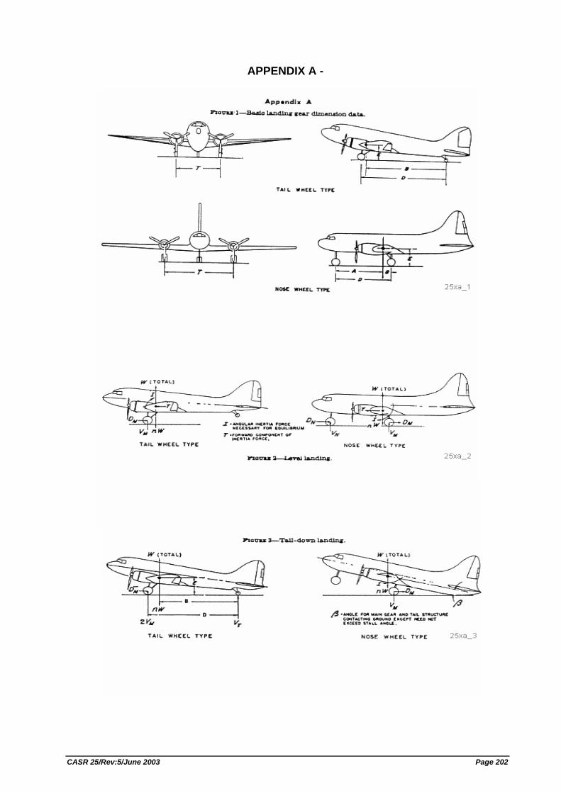
APPENDIX A -
CASR 25/Rev:5/June 2003 Page 202
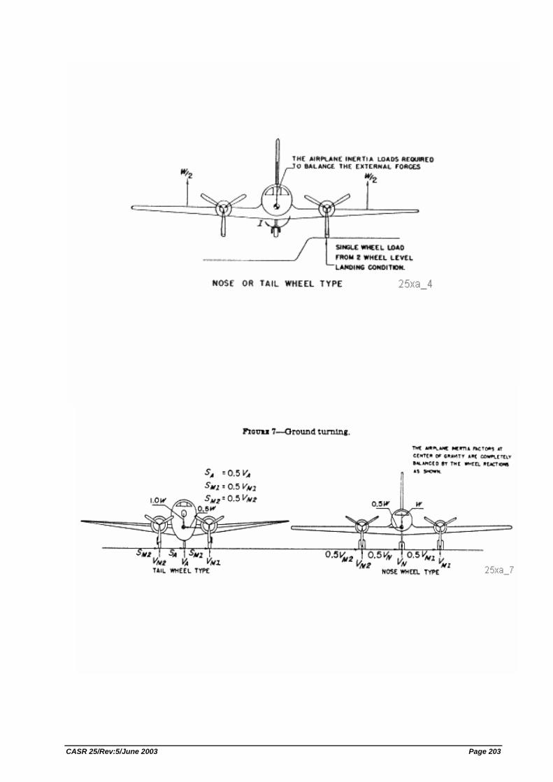
CASR 25/Rev:5/June 2003 Page 203
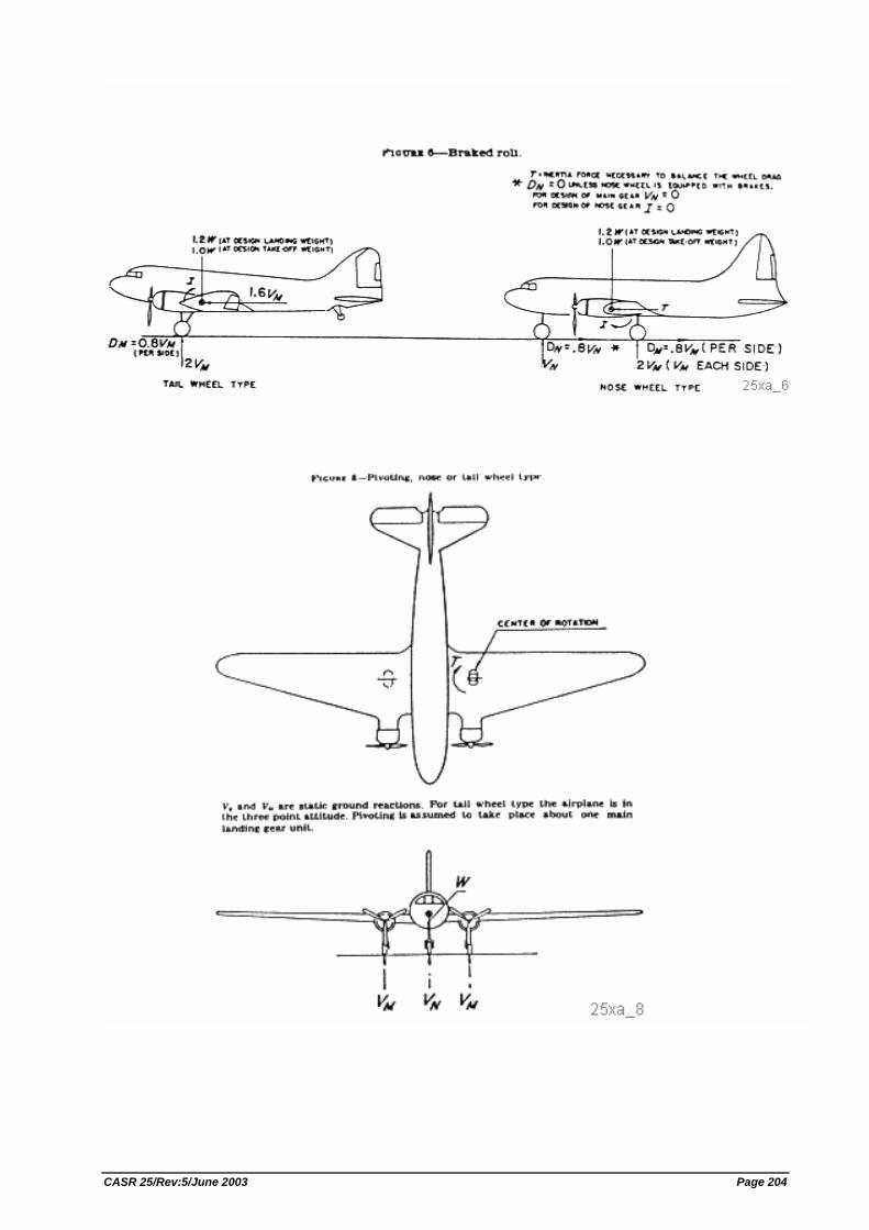
CASR 25/Rev:5/June 2003 Page 204
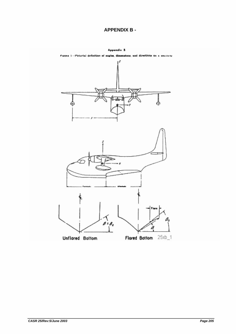
APPENDIX B -
CASR 25/Rev:5/June 2003 Page 205
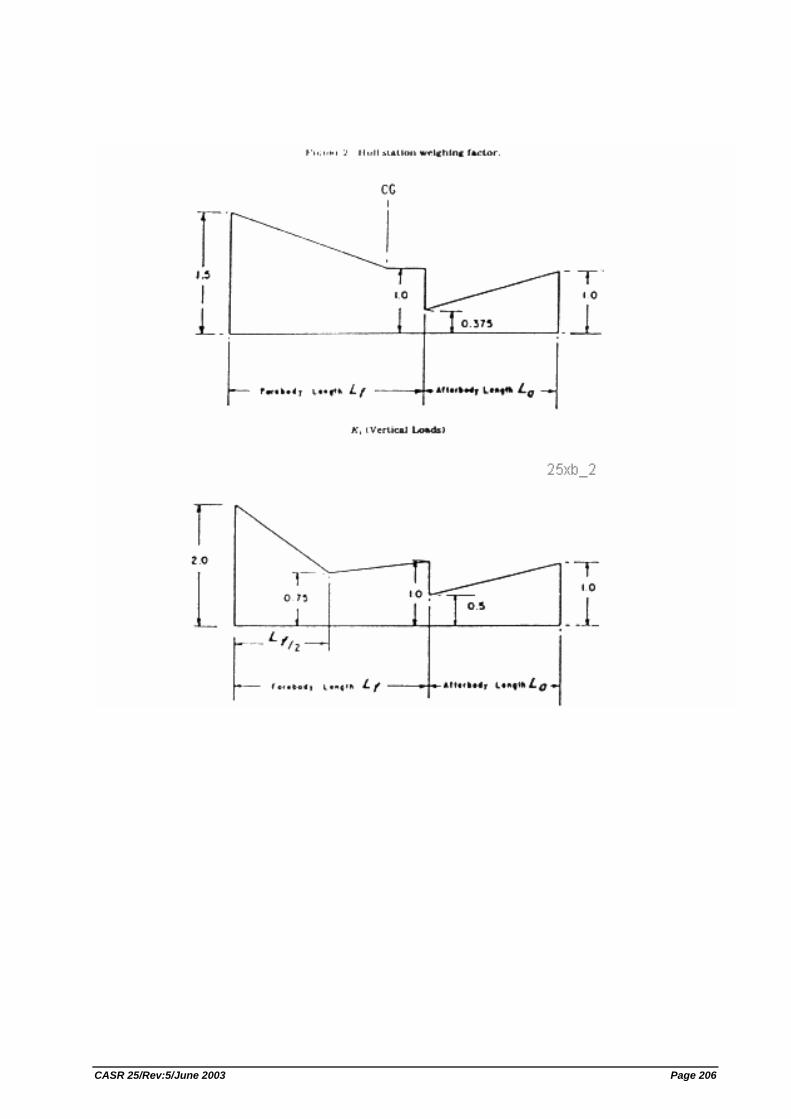
CASR 25/Rev:5/June 2003 Page 206
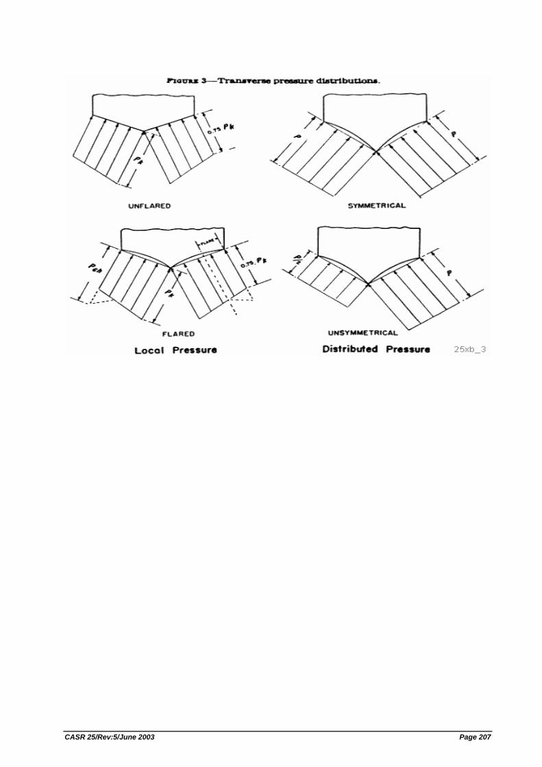
CASR 25/Rev:5/June 2003 Page 207
APPENDIX C -
(a) Continuous maximum icing. The maximum continuous intensity of atmospheric icing conditions (continuous maximum icing) is defined by the variables of the cloud liquid water content, the mean effective diameter of the cloud droplets, the ambient air temperature, and the interrelationship of these three variables as shown in figure 1 of this appendix. The limiting icing envelope in terms of altitude and temperature is given in figure 2 of this appendix. The interrelationship of cloud liquid water content with drop diameter and altitude is determined from figures 1 and 2. The cloud liquid water content for continuous maximum icing conditions of a horizontal extent, other than 17.4 nautical miles, is determined by the value of liquid water content of figure 1, multiplied by the appropriate factor from figure 3 of this appendix.
(b) Intermittent maximum icing. The intermittent maximum intensity of atmospheric icing conditions (intermittent maximum icing) is defined by the variables of the cloud liquid water content, the mean effective diameter of the cloud droplets, the ambient air temperature, and the interrelationship of these three variables as shown in figure 4 of this appendix. The limiting icing envelope in terms of altitude and temperature is given in figure 5 of this appendix. The interrelationship of cloud liquid water content with drop diameter and altitude is determined from figures 4 and 5. The cloud liquid water content for intermittent maximum icing conditions of a horizontal extent, other than 2.6 nautical miles, is determined by the value of cloud liquid water content of figure 4 multiplied by the appropriate factor in figure 6 of this appendix.
CASR 25/Rev:5/June 2003 Page 208
APPENDIX D -
Criteria for determining minimum flight crew. The following are considered by the Agency in determining the minimum flight crew under Sec. 25.1523:
(a) Basic workload functions. The following basic workload functions are considered: (1) Flight path control. (2) Collision avoidance. (3) Navigation. (4) Communications. (5) Operation and monitoring of aircraft engines and systems. (6) Command decisions.
(b) Workload factors. The following workload factors are considered significant when analyzing and demonstrating workload for minimum flight crew determination: (1) The accessibility, ease, and simplicity of operation of all necessary flight,
power, and equipment controls, including emergency fuel shutoff valves, electrical controls, electronic controls, pressurization system controls, and engine controls.
(2) The accessibility and conspicuity of all necessary instruments and failure warning devices such as fire warning, electrical system malfunction, and other failure or caution indicators. The extent to which such instruments or devices direct the proper corrective action is also considered.
(3) The number, urgency, and complexity of operating procedures with particular consideration given to the specific fuel management schedule imposed by center of gravity, structural or other considerations of an airworthiness nature, and to the ability of each engine to operate at all times from a single tank or source which is automatically replenished if fuel is also stored in other tanks.
(4) The degree and duration of concentrated mental and physical effort involved in normal operation and in diagnosing and coping with malfunctions and emergencies.
(5) The extent of required monitoring of the fuel, hydraulic, pressurization, electrical, electronic, deicing, and other systems while enroute.
(6) The actions requiring a crewmember to be unavailable at his assigned duty station, including: observation of systems, emergency operation of any control, and emergencies in any compartment.
(7) The degree of automation provided in the aircraft systems to afford (after failures or malfunctions) automatic crossover or isolation of difficulties to minimize the need for flight crew action to guard against loss of hydraulic or electric power to flight controls or to other essential systems.
(8) The communications and navigation workload. (9) The possibility of increased workload associated with any emergency that may
lead to other emergencies. (10) Incapacitation of a flight crewmember whenever the applicable operating rule
requires a minimum flight crew of at least two pilots.
CASR 25/Rev:5/June 2003 Page 209
(c) Kind of operation authorized. The determination of the kind of operation authorized requires consideration of the operating rules under which the airplane will be operated. Unless an applicant desires approval for a more limited kind of operation. It is assumed that each airplane certificated under this attachment will operate under IFR conditions.
CASR 25/Rev:5/June 2003 Page 210
APPENDIX E
Part I. Limited Weight Credit For Airplanes Equipped With Standby Power
(a) Each applicant for an increase in the maximum certificated takeoff and landing weights of an airplane equipped with a type certificated standby power rocket engine may obtain an increase as specified in paragraph (b) if− (1) The installation of the rocket engine has been approved and it has been
established by flight test that the rocket engine and its controls can be operated safely and reliably at the increase in maximum weight; and
(2) The Airplane Flight Manual, or the placard, markings or manuals required in place thereof, set forth in addition to any other operating limitations the Director General may require, the increased weight approved under this regulation and a prohibition against the operation of the airplane at the approved increased weight when - (i) The installed standby power rocket engines have been stored or
installed in excess of the time limit established by the manufacturer of the rocket engine (usually stenciled on the engine casing); or
(ii) The rocket engine fuel has been expended or discharged.
(b) The currently approved maximum takeoff and landing weights at which an airplane is certificated without a standby power rocket engine installation may be increased by an amount that does not exceed any of the following: (1) An amount equal in pounds to 0.014 IN, where I is the maximum usable
impulse in pounds-seconds available from each standby power rocket engine and N is the number of rocket engines installed.
(2) An amount equal to 5 percent of the maximum certificated weight approved in accordance with the applicable airworthiness regulations without standby power rocket engines installed.
(3) An amount equal to the weight of the rocket engine installation. (4) An amount that, together with the currently approved maximum weight, would
equal the maximum structural weight established for the airplane without standby rocket engines installed.
Part II. Performance Credit for Transport Category Airplanes Equipped With Standby Power
The Director General may grant performance credit for the use of standby power on transport category airplanes. However, the performance credit applies only to the maximum certificated takeoff and landing weights, the takeoff distance, and the takeoff paths, and may not exceed that found by the Director General to result in an overall level of safety in the takeoff, approach, and landing regimes of flight equivalent to that prescribed in the regulations under which the airplane was originally certificated without standby power. For the purposes of this Appendix, "standby power" is power or thrust, or both, obtained from rocket engines for a relatively short period and actuated only in cases of emergency. The following provisions apply:
(a) Takeoff; general. The takeoff data prescribed in paragraphs (2) and (3) of this Appendix must be determined at all weights and altitudes, and at ambient temperatures if applicable, at which performance credit is to be applied.
CASR 25/Rev:5/June 2003 Page 211
(b) Takeoff path. (1) The one engine inoperative takeoff path with standby power in use must be
determined in accordance with the performance requirements of the applicable airworthiness regulations.
(2) The one engine inoperative takeoff path (excluding that part where the airplane is on or just above the takeoff surface) determined in accordance with paragraph (a) of this section must lie above the one engine inoperative takeoff path without standby power at the maximum takeoff weight at which all of the applicable air worthiness requirements are met. For the purpose of this comparison, the flight path is considered to extend to at least a height of 400 feet above the takeoff surface.
(3) The takeoff path with all engines operating, but without the use of standby power, must reflect a conservatively greater overall level of performance than the one engine inoperative takeoff path established in accordance with paragraph (a) of this section. The margin must be established by the Director General to insure safe day-to-day operations, but in no case may it be less than 15 percent. The all engines operating takeoff path must be determined by a procedure consistent with that established in complying with paragraph (a) of this section.
(4) For reciprocating engine powered airplanes, the takeoff path to be scheduled in the Airplane Flight Manual must represent the one engine operative takeoff path determined in accordance with paragraph (a) of this section and modified to reflect the procedure (see paragraph (6)) established by the applicant for flap retraction and attainment of the enroute speed. The scheduled takeoff path must have a positive slope at all points of the airborne portion and at no point must it lie above the takeoff path specified in paragraph (a) of this section.
(c) Takeoff distance. The takeoff distance must be the horizontal distance along the one engine inoperative takeoff path determined in accordance with paragraph (2)(a) from the start of the takeoff to the point where the airplane attains a height of 50 feet above the takeoff surface for reciprocating engine powered airplanes and a height of 35 feet above the takeoff surface for turbine powered airplanes.
(d) Maximum certificated takeoff weights. The maximum certificated takeoff weights must be determined at all altitudes, and at ambient temperatures, if applicable, at which performance credit is to be applied and may not exceed the weights established in compliance with paragraphs (a) and (b) of this section. (1) The conditions of paragraphs (2) (b) through (d) must be met at the maximum
certificated takeoff weight. (2) Without the use of standby power, the airplane must meet all of the enroute
requirements of the applicable airworthiness regulations under which the airplane was originally certificated. In addition, turbine powered airplanes without the use of standby power must meet the final takeoff climb requirements prescribed in the applicable airworthiness regulations.
(e) Maximum certificated landing weights. (1) The maximum certificated landing weights (one engine inoperative approach
and all engine operating landing climb) must be determined at all altitudes, and at ambient temperatures if applicable, at which performance credit is to be
CASR 25/Rev:5/June 2003 Page 212
applied and must not exceed that established in compliance with paragraph (b) of this section.
(2) The flight path, with the engines operating at the power or thrust, or both, appropriate to the airplane configuration and with standby power in use, must lie above the flight path without standby power in use at the maximum weight at which all of the applicable airworthiness requirements are met. In addition, the flight paths must comply with subparagraphs (i) and (ii) of this paragraph. (i) The flight paths must be established without changing the appropriate
airplane configuration. (ii) The flight paths must be carried out for a minimum height of 400 feet
above the point where standby power is actuated.
(f) Airplane configuration, speed, and power and thrust; general. Any change in the airplane's configuration, speed, and power or thrust, or both, must be made in accordance with the procedures established by the applicant for the operation of the airplane in service and must comply with paragraphs (a) through (c) of this section. In addition, procedures must be established for the execution of balked landings and missed approaches. (1) The Director General must find that the procedure can be consistently
executed in service by crews of average skill. (2) The procedure may not involve methods or the use of devices which have not
been proven to be safe and reliable. (3) Allowances must be made for such time delays in the execution of the
procedures as may be reasonably expected to occur during service.
(g) Installation and operation; standby power. The standby power unit and its installation must comply with paragraphs (a) and (b) of this section. (1) The standby power unit and its installation must not adversely affect the safety
of the airplane. (2) The operation of the standby power unit and its control must have proven to
be safe and reliable.
CASR 25/Rev:5/June 2003 Page 213
APPENDIX F -
Part I. Test Criteria and Procedures for Showing Compliance With Sec. 25.853, or 25.855.
(a) Material test criteria− (1) Interior compartments occupied by crew or passengers.
(i) Interior ceiling panels, interior wall panels, partitions, galley structure, large cabinet walls, structural flooring, and materials used in the construction of stowage compartments (other than underseat stowage compartments and compartments for stowing small items such as magazines and maps) must be self-extinguishing when tested vertically in accordance with the applicable portions of part I of this appendix. The average burn length may not exceed 6 inches and the average flame time after removal of the flame source may not exceed 15 seconds. Drippings from the test specimen may not continue to flame for more than an average of 3 seconds after falling.
(ii) Floor covering, textiles (including draperies and upholstery) seat cushions, padding, decorative and nondecorative coated fabrics, leather, trays and galley furnishings, electrical conduit, thermal and acoustical insulation and insulation covering, air ducting, joint and edge covering, liners of Class B and E cargo or baggage compartments, floor panels of Class B, C, D, or E cargo or baggage compartments, insulation blankets, cargo covers and transparencies, molded and thermoformed parts, air ducting joints, and trim strips (decorative and chafing), that are constructed of materials not covered in subparagraph (iv) below, must be self- extinguishing when tested vertically in accordance with the applicable portions of part I of this appendix or other approved equivalent means. The average burn length may not exceed 6 inches, and the average flame time after removal of the flame source may not exceed 15 seconds. Drippings from the test specimen may not continue to flame for more than an average of 5 seconds after falling.
(iii) Motion picture film must be safety film meeting the Approved Standard Specifications.
(iv) Clear plastic windows and signs, parts constructed in whole or in part of elastomeric materials, edge lighted instrument assemblies consisting of two or more instruments in common housing, seat belts, shoulder harnesses, and cargo and baggage tiedown equipment, including containers, bins, pallets, etc., used in passenger or crew compartments, may not have an average burn rate greater than 2.5 inches per minute when tested horizontally in accordance with the applicable portions of this appendix.
(v) Except for small parts (such as knobs, handles, rollers, fasteners, clips, grommets, rub strips, pulleys, and small electrical parts) that would not contribute significantly to the propagation of a fire and for electrical wire and cable insulation, materials in items not specified in paragraphs (a)(1)(i), (ii), (iii), or (iv) of part I of this appendix may not have a burn rate greater than 4.0 inches per minute when tested horizontally in accordance with the applicable portions of this appendix.
CASR 25/Rev:5/June 2003 Page 214
(2) Cargo and baggage compartments not occupied by crew or passengers. (i) Thermal and acoustic insulation (including coverings) used in each
cargo and baggage compartment must be constructed of materials that meet the requirements set forth in paragraph (a)(1)(ii) of part I of this appendix.
(ii) A cargo or baggage compartment defined in Sec. 25.857 as Class B or E must have a liner constructed of materials that meet the requirements of paragraph (a)(1)(ii) of part I of this appendix and separated from the airplane structure (except for attachments). In addition, such liners must be subjected to the 45 degree angle test. The flame may not penetrate (pass through) the material during application of the flame or subsequent to its removal. The average flame time after removal of the flame source may not exceed 15 seconds, and the average glow time may not exceed 10 seconds.
(iii) A cargo or baggage compartment defined in Sec. 25.857 as Class B, C, D, or E must have floor panels constructed of materials which meet the requirements of paragraph (a)(1)(ii) of part I of this appendix and which are separated from the airplane structure (except for attachments). Such panels must be subjected to the 45 degree angle test. The flame may not penetrate (pass through) the material during application of the flame or subsequent to its removal. The average flame time after removal of the flame source may not exceed 15 seconds, and the average glow time may not exceed 10 seconds.
(iv) Insulation blankets and covers used to protect cargo must be constructed of materials that meet the requirements of paragraph (a)(1)(ii) of part I of this appendix. Tiedown equipment (including containers, bins, and pallets) used in each cargo and baggage compartment must be constructed of materials that meet the requirements of paragraph (a)(1)(v) of part I of this appendix.
(3) Electrical system components. Insulation on electrical wire or cable installed in any area of the fuselage must be self-extinguishing when subjected to the 60 degree test specified in part I of this appendix. The average burn length may not exceed 3 inches, and the average flame time after removal of the flame source may not exceed 30 seconds. Drippings from the test specimen may not continue to flame for more than an average of 3 seconds after falling.
(b) Test Procedure− (1) Conditioning. Specimens must be conditioned to 70 + 5 F., and at 50 percent
+5 percent relative humidity until moisture equilibrium is reached or for 24 hours. Each specimen must remain in the conditioning environment until it is subjected to the flame.
(2) Specimen configuration. Except for small parts and electrical wire and cable insulation, materials must be tested either as section cut from a fabricated part as installed in the airplane or as a specimen simulating a cut section, such as a specimen cut from a flat sheet of the material or a model of the fabricated part. The specimen may be cut from any location in a fabricated part; however, fabricated units, such as sandwich panels, may not be separated for test. Except as noted below, the specimen thickness must be no thicker than the minimum thickness to be qualified for use in the airplane. Test specimens of thick foam parts, such as seat cushions, must be 1/2 inch in thickness. Test specimens of materials that must meet the requirements of paragraph (a)(1)(v)
CASR 25/Rev:5/June 2003 Page 215
of part I of this appendix must be no more than 1/8 inch in thickness. Electrical wire and cable specimens must be the same size as used in the airplane. In the case of fabrics, both the warp and fill direction of the weave must be tested to determine the most critical flammability condition. Specimens must be mounted in a metal frame so that the two long edges and the upper edge are held securely during the vertical test prescribed in subparagraph (4) of this paragraph and the two long edges and the edge away from the flame are held securely during the horizontal test prescribed in subparagraph (5) of this paragraph. The exposed area of the specimen must be at least 2 inches wide and 12 inches long, unless the actual size used in the airplane is smaller. The edge to which the burner flame is applied must not consist of the finished or protected edge of the specimen but must be representative of the actual cross-section of the material or part as installed in the airplane. The specimen must be mounted in a metal frame so that all four edges are held securely and the exposed area of the specimen is at least 8 inches by 8 inches during the 45o test prescribed in subparagraph (6) of this paragraph.
(3) Apparatus. Except as provided in subparagraph (7) of this paragraph, vertical and horizontal tests must be conducted in a draft-free cabinet in accordance with Approved Test Method.
(4) Vertical test. A minimum of three specimens must be tested and results averaged. For fabrics, the direction of weave corresponding to the most critical flammability conditions must be parallel to the longest dimension. Each specimen must be supported vertically. The specimen must be exposed to a Bunsen or Tirrill burner with a nominal 3/8 inch I.D. tube adjusted to give a flame of 1.5 inches in height. The minimum flame temperature measured by a calibrated thermocouple pyrometer in the center of the flame must be 1550o F. The lower edge of the specimen must be 3/4 inch above the top edge of the burner. The flame must be applied to the center line of the lower edge of the specimen. For materials covered by paragraph (a)(1)(i) of part I of this appendix, the flame must be applied for 60 seconds and then removed. For materials covered by paragraph (a)(1)(ii) of part I of this appendix, the flame must be applied for 12 seconds and then removed. Flame time, burn length, and flaming time of drippings, if any, may be recorded. The burn length determined in accordance with subparagraph (7) of this paragraph must be measured to the nearest tenth of an inch.
(5) Horizontal test. A minimum of three specimens must be tested and the results averaged. Each specimen must be supported horizontally. The exposed surface, when installed in the aircraft, must be face down for the test. The specimen must be exposed to a Bunsen or Tirrill burner with a nominal 3/8 inch I.D. tube adjusted to give a flame of 1.5 inches in height. The minimum flame temperature measured by a calibrated thermocouple pyrometer in the center of the flame must be 1550o F. The specimen must be positioned so that the edge being tested is centered 3/4 inch above the top of the burner. The flame must be applied for 15 seconds and then removed. A minimum of 10 inches of specimen must be used for timing purposes, approximately 1.5 inches must burn before the burning front reaches the timing zone, and the average burn rate must be recorded.
(6) Forty-five degree test. A minimum of three specimens must be tested and the results averaged. The specimens must be supported at an angle of 45o to a horizontal surface. The exposed surface when installed in the aircraft must be
CASR 25/Rev:5/June 2003 Page 216
face down for the test. The specimens must be exposed to a Bunsen or Tirrill burner with a nominal 3/8 inch I.D. tube adjusted to give a flame of 1.5 inches in height. The minimum flame temperature measured by a calibrated thermocouple pyrometer in the center of the flame must be 1550o F. Suitable precautions must be taken to avoid drafts. The flame must be applied for 30 seconds with one-third contacting the material at the center of the specimen and then removed. Flame time, glow time, and whether the flame penetrates (passes through) the specimen must be recorded.
(7) Sixty degree test. A minimum of three specimens of each wire specification (make and size) must be tested. The specimen of wire or cable (including insulation) must be placed at an angle of 60x with the horizontal in the cabinet specified in subparagraph (3) of this paragraph with the cabinet door open during the test, or must be placed within a chamber approximately 2 feet high by 1 foot by 1 foot, open at the top and at one vertical side (front), and which allows sufficient flow of air for complete combustion, but which is free from drafts. The specimen must be parallel to and approximately 6 inches from the front of the chamber. The lower end of the specimen must be held rigidly clamped. The upper end of the specimen must pass over a pulley or rod and must have an appropriate weight attached to it so that the specimen is held tautly throughout the flammability test. The test specimen span between lower clamp and upper pulley or rod must be 24 inches and must be marked 8 inches from the lower end to indicate the central point for flame application. A flame from a Bunsen or Tirrill burner must be applied for 30 seconds at the test mark. The burner must be mounted underneath the test mark on the specimen, perpendicular to the specimen and at an angle of 30 degrees to the vertical plane of the specimen. The burner must have a nominal bore of 3/8 inch and be adjusted to provide a 3 inch high flame with an inner cone approximately one-third of the flame height. The minimum temperature of the hottest portion of the flame, as measured with a calibrated thermocouple pyrometer, may not be less than 1750o F. The burner must be positioned so that the hottest portion of the flame is applied to the test mark on the wire. Flame time, burn length, and flaming time of drippings, if any, must be recorded. The burn length determined in accordance with paragraph (8) of this paragraph must be measured to the nearest tenth of an inch. Breaking of the wire specimens is not considered a failure.
(8) Burn length. Burn length is the distance from the original edge to the farthest evidence of damage to the test specimen due to flame impingement, including areas of partial or complete consumption, charring, or embrittlement, but not including areas sooted, stained, warped, or discolored, nor areas where material has shrunk or melted away from the heat source.
Part II. Flammability of Seat Cushions
(a) Criteria for Acceptance. Each seat cushion must meet the following criteria: (1) At least three sets of seat bottom and seat back cushion specimens must be
tested. (2) If the cushion is constructed with a fire blocking material, the fire blocking
material must completely enclose the cushion foam core material.
CASR 25/Rev:5/June 2003 Page 217
(3) Each specimen tested must be fabricated using the principal components (i.e., foam core, flotation material, fire blocking material, if used, and dress covering) and assembly processes (representative seams and closures) intended for use in the production articles. If a different material combination is used for the back cushion than for the bottom cushion, both material combinations must be tested as complete specimen sets, each set consisting of a back cushion specimen and a bottom cushion specimen. If a cushion, including outer dress covering, is demonstrated to meet the requirements of this appendix using the oil burner test, the dress covering of that cushion may be replaced with a similar dress covering provided the burn length of the replacement covering, as determined by the test specified in Sec. 25.853(b), does not exceed the corresponding burn length of the dress covering used on the cushion subjected to the oil burner test.
(4) For at least two-thirds of the total number of specimen sets tested, the burn length from the burner must not reach the side of the cushion opposite the burner. The burn length must not exceed 17 inches. Burn length is the perpendicular distance from the inside edge of the seat frame closest to the burner to the farthest evidence of damage to the test specimen due to flame impingement, including areas of partial or complete consumption, charring, or embrittlement, but not including areas sooted, stained, warped, or discolored, or areas where material has shrunk or melted away from the heat source.
(5) The average percentage weight loss must not exceed 10 percent. Also, at least two-thirds of the total number of specimen sets tested must not exceed 10 percent weight loss. All droppings falling from the cushions and mounting stand are to be discarded before the after test weight is determined. The percentage weight loss for a specimen set is the weight of the specimen set before testing less the weight of the specimen set after testing expressed as the percentage of the weight before testing.
(b) Test Conditions. Vertical air velocity should average 25 + 10 fpm at the top of the back seat cushion. Horizontal air velocity should be below 10 fpm just above the bottom seat cushion. Air velocities should be measured with the ventilation hood operating and the burner motor off.
(c) Test Specimens. (1) For each test, one set of cushion specimens representing a seat bottom and
seat back cushion must be used. (2) The seat bottom cushion specimen must be 18 + 1/8 inches (457 + 3 mm)
wide by 20 + 1/8 inches (508 + 3 mm) deep by 4 + 1/8 inches (102 + 3 mm) thick, exclusive of fabric closures and seam overlap.
(3) The seat back cushion specimen must be 18 + 1/8 inches (432 + 3 mm) wide by 25 + 1/8 inches (635 + 3 mm) high by 2 + 1/8 inches (51 + 3 mm) thick, exclusive of fabric closures and seam overlap.
(4) The specimens must be conditioned at 70+5o F (21+2o C) 55% + 10% relative humidity for at least 24 hours before testing.
(d) Test Apparatus. The arrangement of the test apparatus is shown in Figures 1 through 5 and must include the components described in this section. Minor details of the apparatus may vary, depending on the model burner used.
CASR 25/Rev:5/June 2003 Page 218
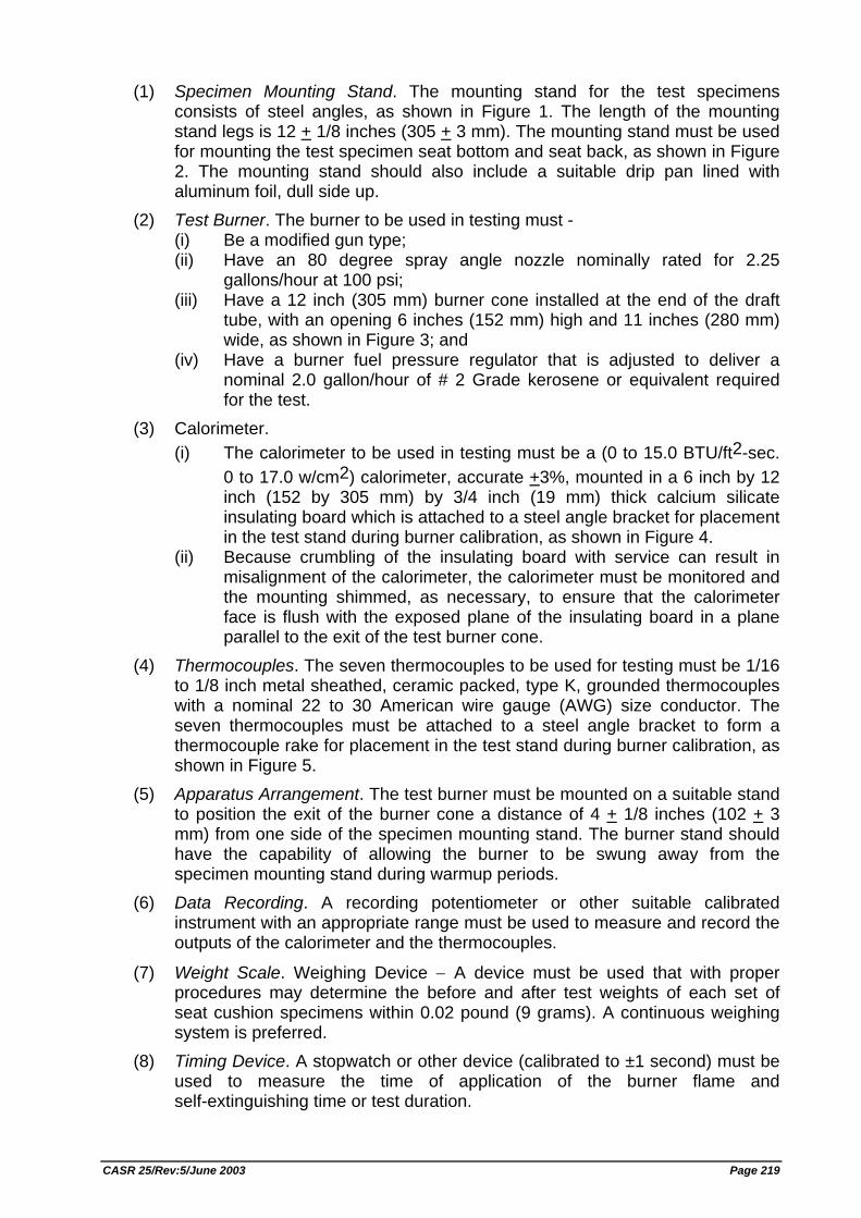
(1) Specimen Mounting Stand. The mounting stand for the test specimens consists of steel angles, as shown in Figure 1. The length of the mounting stand legs is 12 + 1/8 inches (305 + 3 mm). The mounting stand must be used for mounting the test specimen seat bottom and seat back, as shown in Figure 2. The mounting stand should also include a suitable drip pan lined with aluminum foil, dull side up.
(2) Test Burner. The burner to be used in testing must - (i) Be a modified gun type; (ii) Have an 80 degree spray angle nozzle nominally rated for 2.25
gallons/hour at 100 psi; (iii) Have a 12 inch (305 mm) burner cone installed at the end of the draft
tube, with an opening 6 inches (152 mm) high and 11 inches (280 mm) wide, as shown in Figure 3; and
(iv) Have a burner fuel pressure regulator that is adjusted to deliver a nominal 2.0 gallon/hour of # 2 Grade kerosene or equivalent required for the test.
(3) Calorimeter. (i) The calorimeter to be used in testing must be a (0 to 15.0 BTU/ft2-sec.
0 to 17.0 w/cm2) calorimeter, accurate +3%, mounted in a 6 inch by 12 inch (152 by 305 mm) by 3/4 inch (19 mm) thick calcium silicate insulating board which is attached to a steel angle bracket for placement in the test stand during burner calibration, as shown in Figure 4.
(ii) Because crumbling of the insulating board with service can result in misalignment of the calorimeter, the calorimeter must be monitored and the mounting shimmed, as necessary, to ensure that the calorimeter face is flush with the exposed plane of the insulating board in a plane parallel to the exit of the test burner cone.
(4) Thermocouples. The seven thermocouples to be used for testing must be 1/16 to 1/8 inch metal sheathed, ceramic packed, type K, grounded thermocouples with a nominal 22 to 30 American wire gauge (AWG) size conductor. The seven thermocouples must be attached to a steel angle bracket to form a thermocouple rake for placement in the test stand during burner calibration, as shown in Figure 5.
(5) Apparatus Arrangement. The test burner must be mounted on a suitable stand to position the exit of the burner cone a distance of 4 + 1/8 inches (102 + 3 mm) from one side of the specimen mounting stand. The burner stand should have the capability of allowing the burner to be swung away from the specimen mounting stand during warmup periods.
(6) Data Recording. A recording potentiometer or other suitable calibrated instrument with an appropriate range must be used to measure and record the outputs of the calorimeter and the thermocouples.
(7) Weight Scale. Weighing Device − A device must be used that with proper procedures may determine the before and after test weights of each set of seat cushion specimens within 0.02 pound (9 grams). A continuous weighing system is preferred.
(8) Timing Device. A stopwatch or other device (calibrated to ±1 second) must be used to measure the time of application of the burner flame and self-extinguishing time or test duration.
CASR 25/Rev:5/June 2003 Page 219
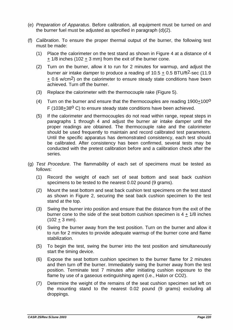
(e) Preparation of Apparatus. Before calibration, all equipment must be turned on and the burner fuel must be adjusted as specified in paragraph (d)(2).
(f) Calibration. To ensure the proper thermal output of the burner, the following test must be made: (1) Place the calorimeter on the test stand as shown in Figure 4 at a distance of 4
+ 1/8 inches (102 + 3 mm) from the exit of the burner cone. (2) Turn on the burner, allow it to run for 2 minutes for warmup, and adjust the
burner air intake damper to produce a reading of 10.5 + 0.5 BTU/ft2-sec (11.9 + 0.6 w/cm2) on the calorimeter to ensure steady state conditions have been achieved. Turn off the burner.
(3) Replace the calorimeter with the thermocouple rake (Figure 5).
(4) Turn on the burner and ensure that the thermocouples are reading 1900+100o F (1038+38o C) to ensure steady state conditions have been achieved.
(5) If the calorimeter and thermocouples do not read within range, repeat steps in paragraphs 1 through 4 and adjust the burner air intake damper until the proper readings are obtained. The thermocouple rake and the calorimeter should be used frequently to maintain and record calibrated test parameters. Until the specific apparatus has demonstrated consistency, each test should be calibrated. After consistency has been confirmed, several tests may be conducted with the pretest calibration before and a calibration check after the series.
(g) Test Procedure. The flammability of each set of specimens must be tested as follows: (1) Record the weight of each set of seat bottom and seat back cushion
specimens to be tested to the nearest 0.02 pound (9 grams). (2) Mount the seat bottom and seat back cushion test specimens on the test stand
as shown in Figure 2, securing the seat back cushion specimen to the test stand at the top.
(3) Swing the burner into position and ensure that the distance from the exit of the burner cone to the side of the seat bottom cushion specimen is 4 + 1/8 inches (102 + 3 mm).
(4) Swing the burner away from the test position. Turn on the burner and allow it to run for 2 minutes to provide adequate warmup of the burner cone and flame stabilization.
(5) To begin the test, swing the burner into the test position and simultaneously start the timing device.
(6) Expose the seat bottom cushion specimen to the burner flame for 2 minutes and then turn off the burner. Immediately swing the burner away from the test position. Terminate test 7 minutes after initiating cushion exposure to the flame by use of a gaseous extinguishing agent (i.e., Halon or CO2).
(7) Determine the weight of the remains of the seat cushion specimen set left on the mounting stand to the nearest 0.02 pound (9 grams) excluding all droppings.
CASR 25/Rev:5/June 2003 Page 220
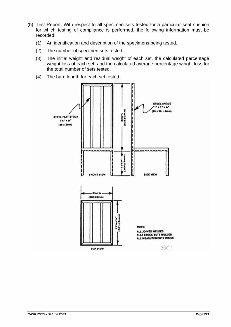
(h) Test Report. With respect to all specimen sets tested for a particular seat cushion for which testing of compliance is performed, the following information must be recorded: (1) An identification and description of the specimens being tested. (2) The number of specimen sets tested. (3) The initial weight and residual weight of each set, the calculated percentage
weight loss of each set, and the calculated average percentage weight loss for the total number of sets tested.
(4) The burn length for each set tested.
CASR 25/Rev:5/June 2003 Page 221
CASR 25/Rev:5/June 2003 Page 222
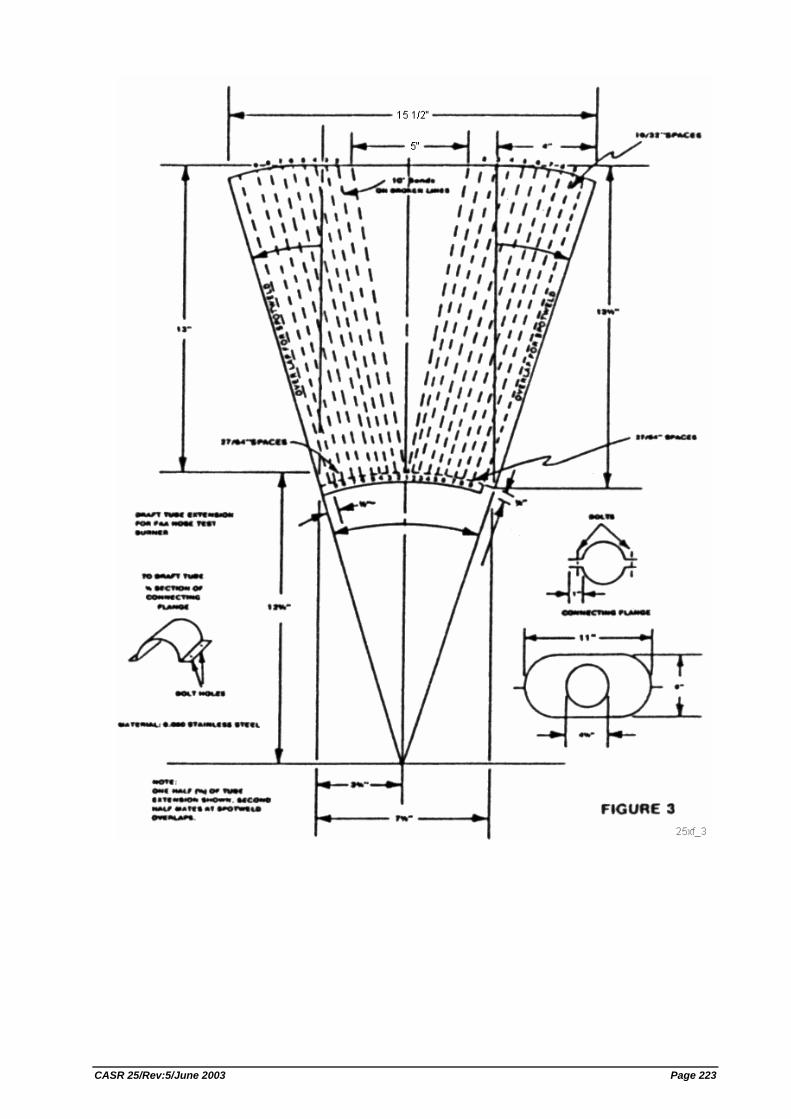
CASR 25/Rev:5/June 2003 Page 223
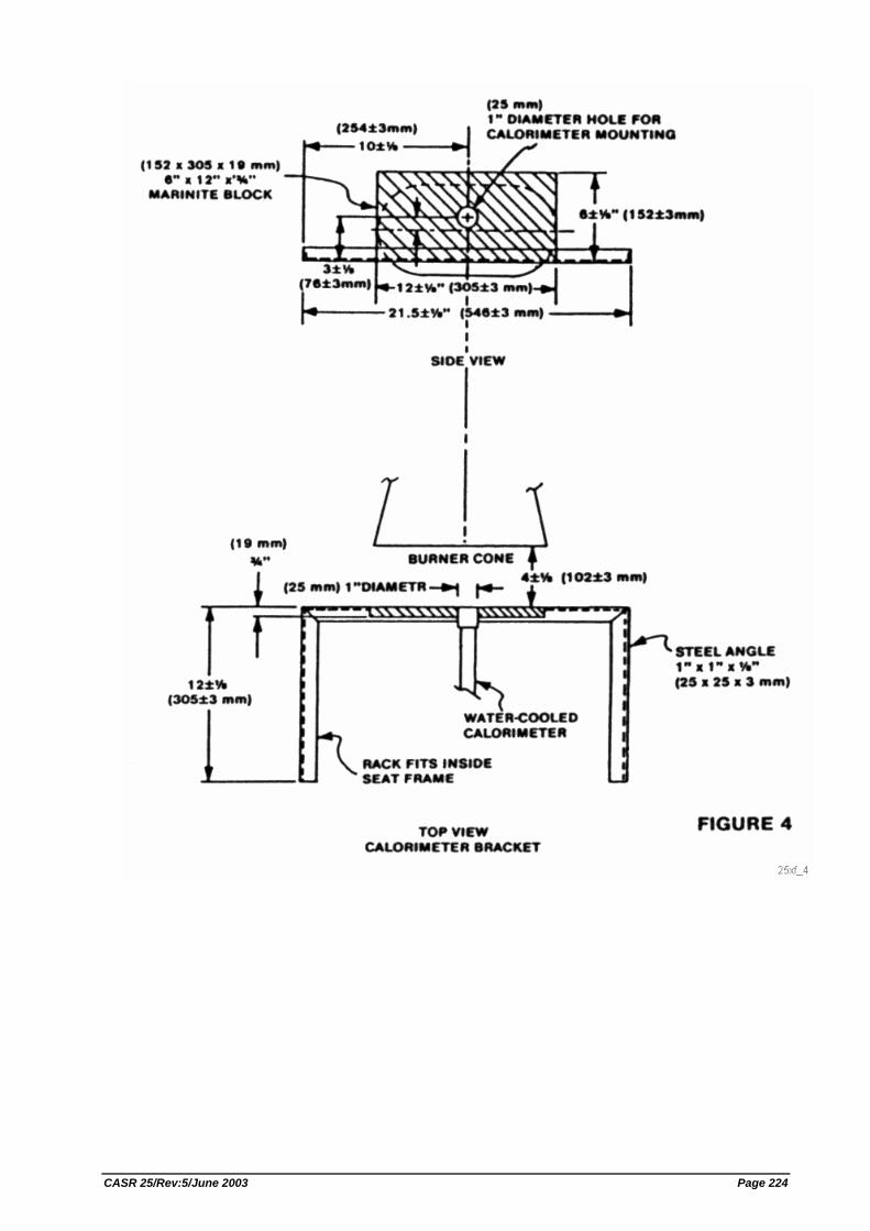
CASR 25/Rev:5/June 2003 Page 224
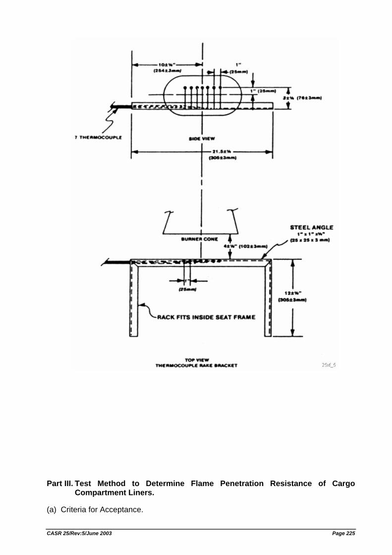
Part III. Test Method to Determine Flame Penetration Resistance of Cargo Compartment Liners.
(a) Criteria for Acceptance.
CASR 25/Rev:5/June 2003 Page 225
(1) At least three specimens of cargo compartment sidewall or ceiling liner panels must be tested.
(2) Each specimen tested must simulate the cargo compartment sidewall or ceiling liner panel, including any design features, such as joints, lamp assemblies, etc., the failure of which would affect the capability of the liner to safely contain a fire.
(3) There must be no flame penetration of any specimen within 5 minutes after application of the flame source, and the peak temperature measured at 4 inches above the upper surface of the horizontal test sample must not exceed 400 degrees F.
(b) Summary of Method. This method provides a laboratory test procedure for measuring the capability of cargo compartment lining materials to resist flame penetration with a 2 gallon per hour (GPH) #2 Grade kerosene or equivalent burner fire source. Ceiling and sidewall liner panels may be tested individually provided a baffle is used to simulate the missing panel. Any specimen that passes the test as a ceiling liner panel may be used as a sidewall liner panel.
(c) Test Specimens. (1) The specimen to be tested must measure 16 + 1/8 inches (406 + 3 mm) by 24
+ 1/8 inches (610 + 3 mm).
(2) The specimens must be conditioned at 70o F + 5o F (21o C + 2o C) and 55% + 5% humidity for at least 24 hours before testing.
(d) Test Apparatus. The arrangement of the test apparatus, which is shown in Figure 3 of Part II and Figures 1 through 3 of this part of Appendix F, must include the components described in this section. Minor details of the apparatus may vary, depending on the model of the burner used. (1) Specimen Mounting Stand. The mounting stand for the test specimens
consists of steel angles as shown in Figure 1. (2) Test Burner. The burner to be used in testing must -
(i) Be a modified gun type. (ii) Use a suitable nozzle and maintain fuel pressure to yield a 2 GPH fuel
flow. For example: an 80 degree nozzle nominally rated at 2.25 GPH and operated at 85 pounds per square inch (PSI) gauge to deliver 2.03 GPH.
(iii) Have a 12 inch (305 mm) burner extension installed at the end of the draft tube with an opening 6 inches (152 mm) high and 11 inches (280 mm) wide as shown in Figure 3 of Part II of this appendix.
(iv) Have a burner fuel pressure regulator that is adjusted to deliver a nominal 2.0 GPH of #2 Grade kerosene or equivalent.
(3) Calorimeter. (i) The calorimeter to be used in testing must be a total heat flux Foil Type
Gardon Gauge of an appropriate range (approximately 0 to 15.0 British thermal unit (BTU) per ft2 sec, 0 to 17.0 watts/cm2). The calorimeter must be mounted in a 6 inch by 12 inch (152 by 305 mm) by 3/4 inch (19 mm) thick insulating block which is attached to a steel angle bracket for placement in the test stand during burner calibration as shown in Figure 2 of this part of this appendix.
CASR 25/Rev:5/June 2003 Page 226
(ii) The insulating block must be monitored for deterioration and the mounting shimmed as necessary to ensure that the calorimeter face is parallel to the exit plane of the test burner cone.
(4) Thermocouples. The seven thermocouples to be used for testing must be 1/16 inch ceramic sheathed, type K, grounded thermocouples with a nominal 30 American wire gauge (AWG) size conductor. The seven thermocouples must be attached to a steel angle bracket to form a thermocouple rake for placement in the test stand during burner calibration as shown in Figure 3 of this part of this appendix.
(5) Apparatus Arrangement. The test burner must be mounted on a suitable stand to position the exit of the burner cone a distance of 8 inches from the ceiling liner panel and 2 inches from the sidewall liner panel. The burner stand should have the capability of allowing the burner to be swung away from the test specimen during warm up periods.
(6) Instrumentation. A recording potentiometer or other suitable instrument with an appropriate range must be used to measure and record the outputs of the calorimeter and the thermocouples.
(7) Timing Device. A stopwatch or other device must be used to measure the time of flame application and the time of flame penetration, if it occurs.
(e) Preparation of Apparatus. Before calibration, all equipment must be turned on and allowed to stabilize, and the burner fuel flow must be adjusted as specified in paragraph (d)(2).
(f) Calibration. To ensure the proper thermal output of the burner the following test must be made: (1) Remove the burner extension from the end of the draft tube. Turn on the
blower portion of the burner without turning the fuel or igniters on. Measure the air velocity using a hot wire anemometer in the center of the draft tube across the face of the opening. Adjust the damper such that the air velocity is in the range of 1550 to 1800 ft./min. If tabs are being used at the exit of the draft tube, they must be removed prior to this measurement. Reinstall the draft tube extension cone.
(2) Place the calorimeter on the test stand as shown in Figure 2 at a distance of 8 inches (203 mm) from the exit of the burner cone to simulate the position of the horizontal test specimen.
(3) Turn on the burner, allow it to run for 2 minutes for warm up, and adjust the damper to produce a calorimeter reading of 8.0 + 0.5 BTU per ft2 sec. (9.1 + 0.6 Watts/cm2).
(4) Replace the calorimeter with the thermocouple rake (see Figure 3). (5) Turn on the burner and ensure that each of the seven thermocouples reads
1700o F + 100o F. (927o C + 38o C.) to ensure steady state conditions have been achieved. If the temperature is out of this range, repeat steps 2 through 5 until proper readings are obtained.
(6) Turn off the burner and remove the thermocouple rake. (7) Repeat (1) to ensure that the burner is in the correct range.
CASR 25/Rev:5/June 2003 Page 227
(g) Test Procedure. (1) Mount a thermocouple of the same type as that used for calibration at a
distance of 4 inches (102 mm) above the horizontal (ceiling) test specimen. The thermocouple should be centered over the burner cone.
(2) Mount the test specimen on the test stand shown in Figure 1 in either the horizontal or vertical position. Mount the insulating material in the other position.
(3) Position the burner so that flames will not impinge on the specimen, turn the burner on, and allow it to run for 2 minutes. Rotate the burner to apply the flame to the specimen and simultaneously start the timing device.
(4) Expose the test specimen to the flame for 5 minutes and then turn off the burner. The test may be terminated earlier if flame penetration is observed.
(5) When testing ceiling liner panels, record the peak temperature measured 4 inches above the sample.
(6) Record the time at which flame penetration occurs if applicable.
(h) Test Report. The test report must include the following: (1) A complete description of the materials tested including type, manufacturer,
thickness, and other appropriate data. (2) Observations of the behavior of the test specimens during flame exposure
such as delamination, resin ignition, smoke, etc., including the time of such occurrence.
(3) The time at which flame penetration occurs, if applicable, for each of the three specimens tested.
(4) Panel orientation (ceiling or sidewall).
CASR 25/Rev:5/June 2003 Page 228
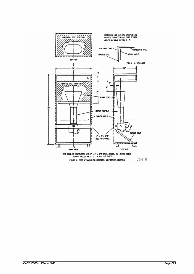
CASR 25/Rev:5/June 2003 Page 229
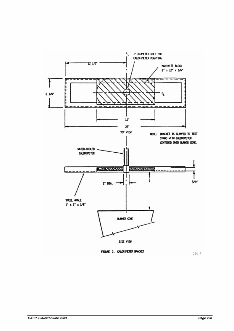
CASR 25/Rev:5/June 2003 Page 230
CASR 25/Rev:5/June 2003 Page 231
Part IV. Test Method to Determine the Heat Release Rate From Cabin Materials Exposed to Radiant Heat.
(a) Summary of Method. Three or more specimens representing the completed aircraft component are tested. Each test specimen is injected into an environmental chamber through which a constant flow of air passes. The specimen's exposure is determined by a radiant heat source adjusted to produce, on the specimen, the desired total heat flux of 3.5 W/cm2. The specimen is tested with the exposed surface vertical. Combustion is initiated by piloted ignition. The combustion products leaving the chamber are monitored in order to calculate the release rate of heat.
(b) Apparatus. The Ohio State University (OSU) rate of heat release apparatus, as described below, is used. This is a modified version of the rate of heat release apparatus standardized by the American Society of Testing and Materials (ASTM), ASTM E-906. (1) This apparatus is shown in Figures 1A and 1B of this part IV. All exterior
surfaces of the apparatus, except the holding chamber, must be insulated with 1 inch (25 mm) thick, low density, high temperature, fiberglass board insulation. A gasketed door, through which the sample injection rod slides, must be used to form an airtight closure on the specimen hold chamber.
(2) Thermopile. The temperature difference between the air entering the environmental chamber and that leaving must be monitored by a thermopile having five hot, and five cold, 24 gauge Chromel-Alumel junctions. The hot junctions must be spaced across the top of the exhaust stack, 0.38 inches (10 mm) below the top of the chimney. The thermocouples must have a 0.050 ±0.010 inch (1.3 ±0.3 mm) diameter, ball-type, welded tip. One thermocouple must be located in the geometric center, with the other four located 1.18 inch (30 mm) from the center along the diagonal toward each of the corners (Figure 5 of this part IV). The cold junctions must be located in the pan below the lower air distribution plate (see paragraph (b)(4) of this part IV). Thermopile hot junctions must be cleared of soot deposits as needed to maintain the calibrated sensitivity.
(3) Radiation Source. A radiant heat source incorporating four Type LL silicon carbide elements, 20 inches (508 mm) long by 0.63 inch (16 mm) O.D., must be used, as shown in Figures 2A and 2B of this part IV. The heat source must have a nominal resistance of 1.4 ohms and be capable of generating a flux up to 100 kW/m2. The silicone carbide elements must be mounted in the stainless steel panel box by inserting them through 0.63 inch (16 mm) holes in 0.03 inch (1 mm) thick ceramic fiber or calcium-silicate millboard. Locations of the holes in the pads and stainless steel cover plates are shown in Figure 2B of this part IV. The truncated diamond-shaped mask of 0.042 ±0.002 inch (1.07 ±0.05 mm) stainless steel must be added to provide uniform heat flux density over the area occupied by the vertical sample.
(4) Air Distribution System. The air entering the environmental chamber must be distributed by a 0.25 inch (6.3 mm) thick aluminum plate having eight No. 4 drill-holes, located 2 inches (51 mm) from sides on 4 inch (102 mm) centers, mounted at the base of the environmental chamber. A second plate of 18 gauge stainless steel having 120, evenly spaced, No. 28 drill holes must be mounted 6 inches (152 mm) above the aluminum plate. A well-regulated air supply is required. The air-supply manifold at the base of the pyramidal
CASR 25/Rev:5/June 2003 Page 232
section must have 48, evenly spaced, No. 26 drill holes located 0.38 inch (10 mm) from the inner edge of the manifold, resulting in an airflow split of approximately three to one within the apparatus.
(5) Exhaust Stack. An exhaust stack, 5.25 x 2.75 inches (133 x 70 mm) in cross section, and 10 inches (254 mm) long, fabricated from 28 gauge stainless steel must be mounted on the outlet of the pyramidal section. A. 1.0 x 3.0 inch (25 x 76 mm) baffle plate of 0.018 ±0.002 inch (0.50 ±0.05 mm) stainless steel must be centered inside the stack, perpendicular to the air flow, 3 inches (76 mm) above the base of the stack.
(6) Specimen Holders. (i) The specimen must be tested in a vertical orientation. The specimen
holder (Figure 3 of this part IV) must incorporate a frame that touches the specimen (which is wrapped with aluminum foil as required by paragraph (d)(3) of this Part) along only the 0.25 inch (6 mm) perimeter. A "V" shaped spring is used to hold the assembly together. A detachable 0.50 x 0.50 x 5.91 inch (12 x 12 x 150 mm) drip pan and two 0.020 inch (0.5 mm) stainless steel wires (as shown in Figure 3 of this part IV) must be used for testing materials prone to melting and dripping. The positioning of the spring and frame may be changed to accommodate different specimen thicknesses by inserting the retaining rod in different holes on the specimen holder.
(ii) Since the radiation shield described in ASTM E-906 is not used, a guide pin must be added to the injection mechanism. This fits into a slotted metal plate on the injection mechanism outside of the holding chamber. It can be used to provide accurate positioning of the specimen face after injection. The front surface of the specimen must be 3.9 inches (100 mm) from the closed radiation doors after injection.
(iii) The specimen holder clips onto the mounted bracket (Figure 3 of this part IV). The mounting bracket must be attached to the injection rod by three screws that pass through a wide-area washer welded onto a 1/2 inch (13 mm) nut. The end of the injection rod must be threaded to screw into the nut, and a 0.020 inch (5.1 mm) thick wide area washer must be held between two 1/2 inch (13 mm) nuts that are adjusted to tightly cover the hole in the radiation doors through which the injection rod or calibration calorimeter pass.
(7) Calorimeter. A total flux type calorimeter must be mounted in the center of a 1/2 inch Kaowool "M" board inserted in the sample holder to measure the total heat flux. The calorimeter must have a view angle of 180 degrees and be calibrated for incident flux. The calorimeter calibration must be acceptable to the Administrator.
(8) Pilot-Flame Positions. Pilot ignition of the specimen must be accomplished by simultaneously exposing the specimen to a lower pilot burner and an upper pilot burner, as described in paragraph (b)(8)(i) and (b)(8)(ii) or (b)(8)(iii) of this part IV, respectively. Since intermittent pilot flame extinguishment for more than 3 seconds would invalidate the test results, a spark ignitor may be installed to ensure that the lower pilot burner remains lighted. (i) Lower Pilot Burner. The pilot-flame tubing must be 0.25 inch (6.3 mm)
O.D., 0.03 inch (0.8 mm) wall, stainless steel tubing. A mixture of 120 cm3/min. of methane and 850 cm3/min. of air must be fed to the lower pilot flame burner. The normal position of the end of the pilot burner
CASR 25/Rev:5/June 2003 Page 233
tubing is 0.40 inch (10 mm) from and perpendicular to the exposed vertical surface of the specimen. The centerline at the outlet of the burner tubing must intersect the vertical centerline of the sample at a point 0.20 inch (5 mm) above the lower exposed edge of the specimen.
(ii) Standard Three-Hole Upper Pilot Burner. The pilot burner must be a straight length of 0.25 inch (6.3 mm) O.D., 0.03 inch (0.8 mm) wall, stainless steel tubing that is 14 inches (360 mm) long. One end of the tubing must be closed, and three No. 40 drill holes must be drilled into the tubing, 2.38 inch (60 mm) apart, for gas ports, all radiating in the same direction. The first hole must be 0.19 inch (5 mm) from the closed end of the tubing. The tube must be positioned 0.75 inch (19 mm) above and 0.75 inch (19 mm) behind the exposed upper edge of the specimen. The middle hole must be in the vertical plane perpendicular to the exposed surface of the specimen which passes through its vertical centerline and must be pointed toward the radiation source. The gas supplied to the burner must be methane and must be adjusted to produce flame lengths of 1 inch (25 mm).
(iii) Optional Fourteen-Hole Upper Pilot Burner. This burner may be used in lieu of the standard three-hole burner described in paragraph (b)(8)(ii) of this part IV. The pilot burner must be a straight length of 0.25 inch (6.3 mm) O.D., 0.03 inch (0.8 mm) wall, stainless steel tubing that is 15.75 inches (400 mm) long. One end of the tubing must be closed, and 14 No. 59 drill holes must be drilled into the tubing, 0.50 inch (13 mm) apart, for gas ports, all radiating in the same direction. The first hole must be 0.50 inch (13 mm) from the closed end of the tubing. The tube must be positioned above the specimen holder so that the holes are placed above the specimen as shown in Figure 1B of this part IV. The fuel supplied to the burner must be methane mixed with air in a ratio of approximately 50/50 by volume. The total gas flow must be adjusted to produce flame lengths of 1 inch (25 mm). When the gas/air ratio and the flow rate are properly adjusted, approximately 0.25 inch (6 mm) of the flame length appears yellow in color.
(c) Calibration of Equipment. (1) Heat Release Rate. A calibration burner, as shown in Figure 4, must be placed
over the end of the lower pilot flame tubing using a gas tight connection. The flow of gas to the pilot flame must be at least 99 percent methane and must be accurately metered. Prior to usage, the wet test meter must be properly leveled and filled with distilled water to the tip of the internal pointer while no gas is flowing. Ambient temperature and pressure of the water are based on the internal wet test meter temperature. A baseline flow rate of approximately 1 liter/min. must be set and increased to higher preset flows of 4, 6, 8, 6 and 4 liters/min. Immediately prior to recording methane flow rates, a flow rate of 8 liters/min. must be used for 2 minutes to precondition the chamber. This is not recorded as part of calibration. The rate must be determined by using a stopwatch to time a complete revolution of the wet test meter for both the baseline and higher flow, with the flow returned to baseline before changing to the next higher flow. The thermopile baseline voltage must be measured. The gas flow to the burner must be increased to the higher preset flow and allowed to burn for 2.0 minutes, and the thermopile voltage must be measured. The sequence must be repeated until all five values have been determined. The average of the five values must be used as the calibration factor. The
CASR 25/Rev:5/June 2003 Page 234
procedure must be repeated if the percent relative standard deviation is greater than 5 percent. Calculations are shown in paragraph (f) of this part IV.
(2) Flux Uniformity. Uniformity of flux over the specimen must be checked periodically and after each heating element change to determine if it is within acceptable limits of plus or minus 5 percent.
(3) As noted in paragraph (b)(2) of this part IV, thermopile hot junctions must be cleared of soot deposits as needed to maintain the calibrated sensitivity.
(d) Preparation of Test Specimens. (1) The test specimens must be representative of the aircraft component in regard
to materials and construction methods. The standard size for the test specimens is 5.91 ±0.03 x 5.91 ±0.03 inches (149 ±1 x 149 ±1 mm). The thickness of the specimen must be the same as that of the aircraft component it represents up to a maximum thickness of 1.75 inches (45 mm). Test specimens representing thicker components must be 1.75 inches (45 mm).
(2) Conditioning. Specimens must be conditioned as described in Part 1 of this appendix.
(3) Mounting. Each test specimen must be wrapped tightly on all sides of the specimen, except for the one surface that is exposed with a single layer of 0.001 inch (0.025 mm) aluminum foil.
(e) Procedure. (1) The power supply to the radiant panel must be set to produce a radiant flux of
3.5 ±0.05 W/cm2, as measured at the point the center of the specimen surface will occupy when positioned for the test. The radiant flux must be measured after the air flow through the equipment is adjusted to the desired rate.
(2) After the pilot flames are lighted, their position must be checked as described in paragraph (b)(8) of this part IV.
(3) Air flow through the apparatus must be controlled by a circular plate orifice located in a 1.5 inch (38.1 mm) I.D. pipe with two pressure measuring points, located 1.5 inches (38 mm) upstream and 0.75 inches (19 mm) downstream of the orifice plate. The pipe must be connected to a manometer set at a pressure differential of 7.87 inches (200 mm) of Hg. (See Figure 1B of this part IV.) The total air flow to the equipment is approximately 0.04 m3/seconds. The stop on the vertical specimen holder rod must be adjusted so that the exposed surface of the specimen is positioned 3.9 inches (100 mm) from the entrance when injected into the environmental chamber.
(4) The specimen must be placed in the hold chamber with the radiation doors closed. The airtight outer door must be secured, and the recording devices must be started. The specimen must be retained in the hold chamber for 60 seconds, plus or minus 10 seconds, before injection. The thermopile "zero" value must be determined during the last 20 seconds of the hold period. The sample must not be injected before completion of the "zero" value determination.
(5) When the specimen is to be injected, the radiation doors must be opened. After the specimen is injected into the environmental chamber, the radiation doors must be closed behind the specimen.
CASR 25/Rev:5/June 2003 Page 235
(6) [Reserved] (7) Injection of the specimen and closure of the inner door marks time zero. A
record of the thermopile output with at least one data point per second must be made during the time the specimen is in the environmental chamber.
(8) The test duration is five minutes. The lower pilot burner and the upper pilot burner must remain lighted for the entire duration of the test, except that there may be intermittent flame extinguishment for periods that do not exceed 3 seconds. Furthermore, if the optional three-hole upper burner is used, at least two flamelets must remain lighted for the entire duration of the test, except that there may be intermittent flame extinguishment of all three flamelets for periods that do not exceed 3 seconds.
(9) A minimum of three specimens must be tested.
(f) Calculations. (1) The calibration factor is calculated as follows:
Kh = ((F1 - F0)/(V1 - V0)) x ((210.8 - 22) kcal/mole) x (273/Ta) x ((P - Pv)/760) x (mole CH4STP/22.41) x (WATT.min/0.01433 kcal) x (Kw/1000 w)
Where− F0 = flow of methane at baseline (1pm) F1 = higher preset flow of methane (1pm) V0 = thermopile voltage at baseline (mv) V1 = thermopile voltage at higher flow (mv) Ta = Ambient temperature (K) P = mbient pressure (mm Hg) Pv = Water vapor pressure (mm Hg)
(2) Heat release rates may be calculated from the reading of the thermopile output voltage at any instant of time as:
HRR = (Vm x Kh)/0.2323 m2 HRR = heat release rate (kw/m2) VB = baseline voltage (mv) Vm = measured thermopile voltage (mv) Kh = calibration factor (kw/mv)
(3) The integral of the heat release rate is the total heat release as a function of time and is calculated by multiplying the rate by the data sampling frequency in minutes and summing the time from zero to two minutes.
(g) Criteria. The total positive heat release over the first two minutes of exposure for each of the three or more samples tested must be averaged, and the peak heat release rate for each of the samples must be averaged. The average total heat release must not exceed 65 kilowatt-minutes per square meter, and the average peak heat release rate must not exceed 65 kilowatts per square meter.
(h) Report. The test report must include the following for each specimen tested: (1) Description of the specimen.
(2) Radiant heat flux to the specimen, expressed in W/cm2.
CASR 25/Rev:5/June 2003 Page 236
(3) Data giving release rates of heat (in kW/m2) as a function of time, either graphically or tabulated at intervals no greater than 10 seconds. The calibration factor (kn) must be recorded.
(4) If melting, sagging, delaminating, or other behavior that affects the exposed surface area or the mode of burning occurs, these behaviors must be reported, together with the time at which such behaviors were observed.
(5) The peak heat release and the 2 minute integrated heat release rate must be reported.
CASR 25/Rev:5/June 2003 Page 237
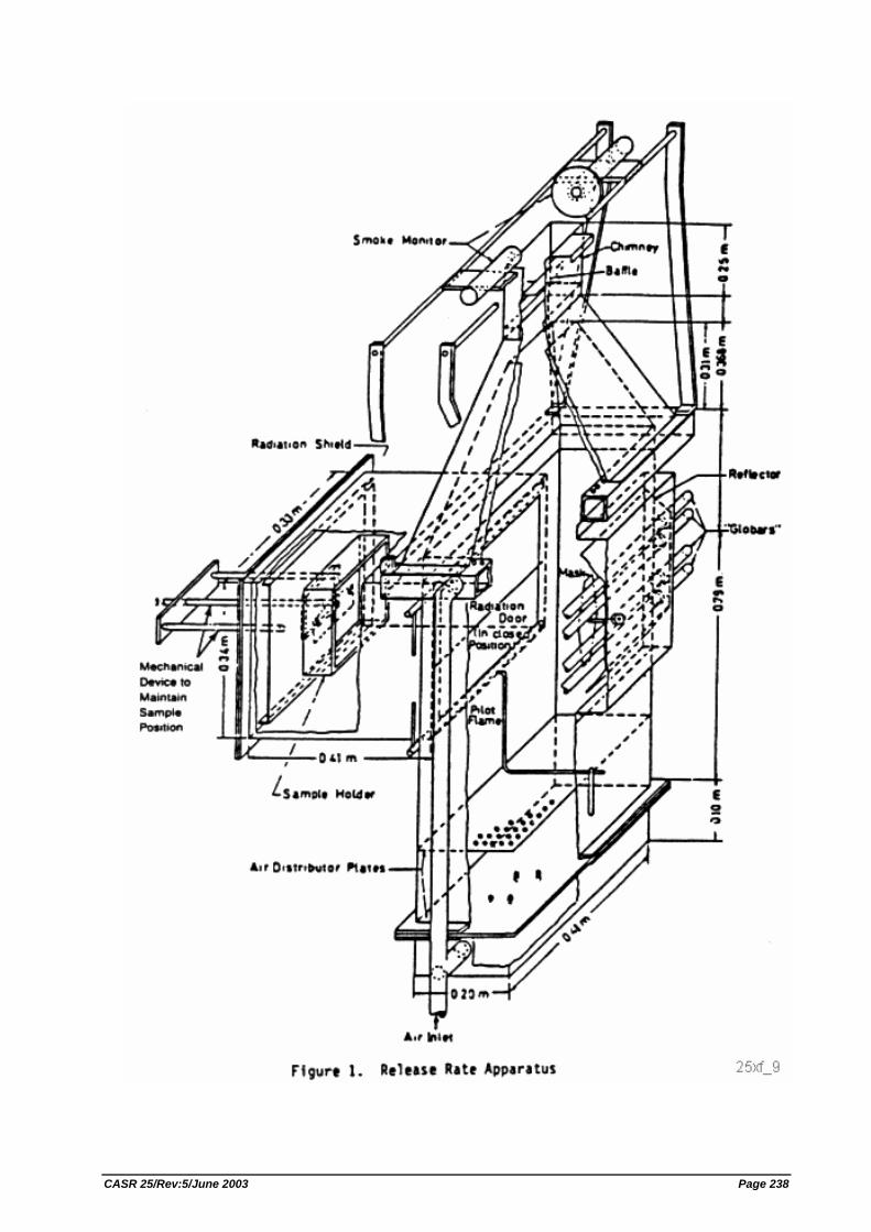
CASR 25/Rev:5/June 2003 Page 238
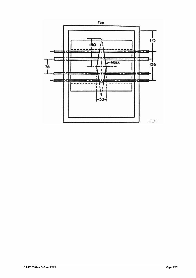
CASR 25/Rev:5/June 2003 Page 239
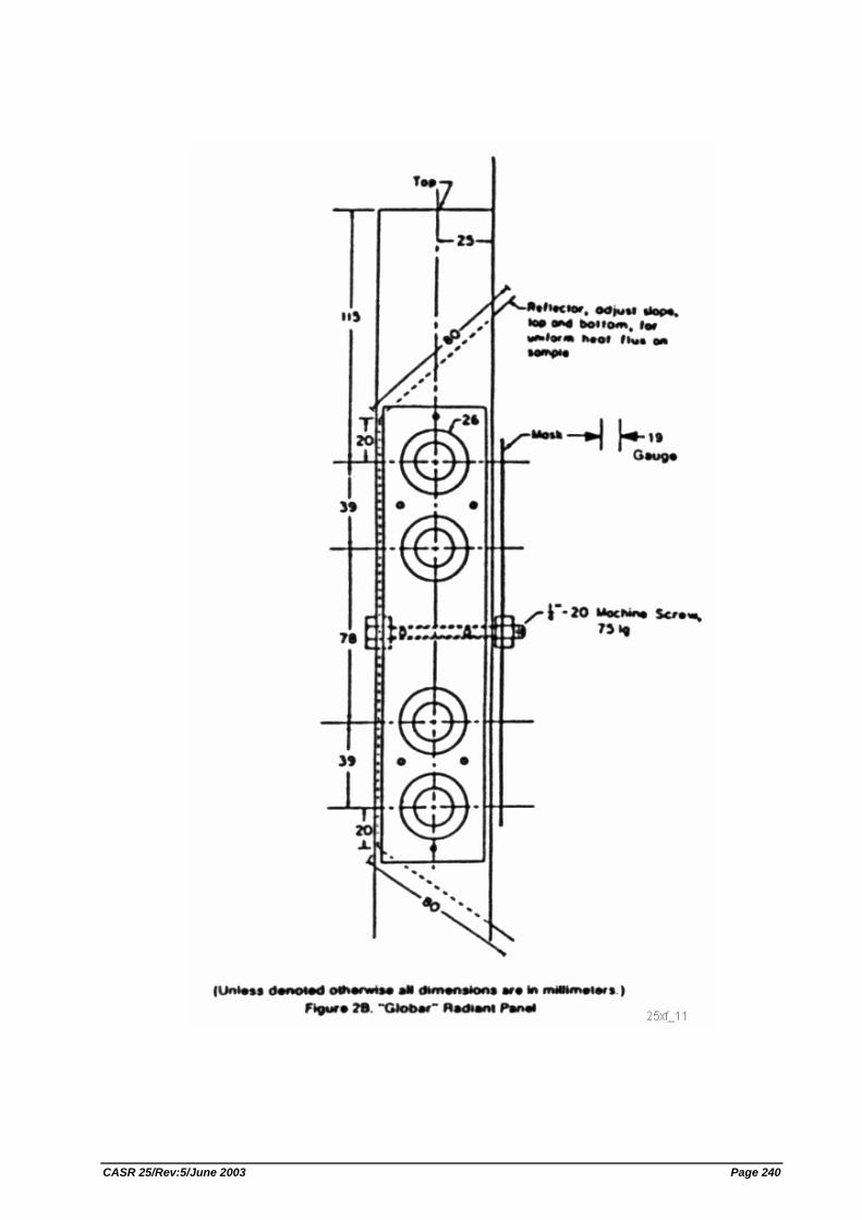
CASR 25/Rev:5/June 2003 Page 240
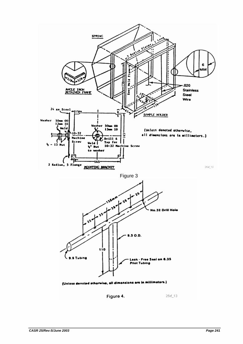
Figure 3
CASR 25/Rev:5/June 2003 Page 241
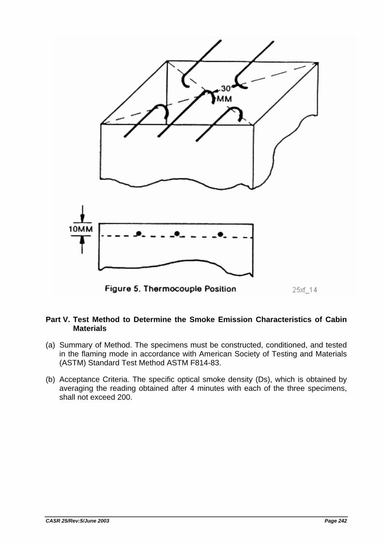
Part V. Test Method to Determine the Smoke Emission Characteristics of Cabin Materials
(a) Summary of Method. The specimens must be constructed, conditioned, and tested in the flaming mode in accordance with American Society of Testing and Materials (ASTM) Standard Test Method ASTM F814-83.
(b) Acceptance Criteria. The specific optical smoke density (Ds), which is obtained by averaging the reading obtained after 4 minutes with each of the three specimens, shall not exceed 200.
CASR 25/Rev:5/June 2003 Page 242
APPENDIX G - CONTINUOUS GUST DESIGN CRITERIA
The continuous gust design criteria in this appendix must be used in establishing the dynamic response of the airplane to vertical and lateral continuous turbulence unless a more rational criteria is used. The following gust load requirements apply to mission analysis and design envelope analysis:
(a) The limit gust loads utilizing the continuous turbulence concept must be determined in accordance with the provisions of either paragraph (b) or paragraphs (c) and (d) of this appendix.
(b) Design envelope analysis. The limit loads must be determined in accordance with the following: (1) All critical altitudes, weights, and weight distributions, as specified in Sec.
25.321(b), and all critical speeds within the ranges indicated in paragraph (b)(3) of this appendix must be considered.
(2) Values of A (ratio of root-mean-square incremental load root-mean-square gust velocity) must be determined by dynamic analysis. The power spectral density of the atmospheric turbulence must be as given by the equation–
φ(Ω) = σ2L/π × [1 + (8/3)(1.339LΩ)2]/
[1 + (1.339LΩ)2]11/6 where:
φ = power-spectral density (ft/sec)2/rad/ft
σ = root-mean-square gust velocity, ft/sec
Ω = reduced frequency, radians per foot L = 2,500 ft
(3) The limit loads must be obtained by multiplying the A-bar values determined by the dynamic analysis by the following values of the gust velocity Uσ: (i) At speed Vc: Uσ = 85 fps true gust velocity in the interval 0 to 30,000 ft.
altitude and is linearly decreased to 30 fps true gust velocity at 80,000 ft. altitude. Where the Director General finds that a design is comparable to a similar design with extensive satisfactory service experience, it will be acceptable to select Uσ at Vc less than 85 fps, but not less than 75 fps, with linear decrease from that value at 20,000 feet to 30 fps at 80,000 feet. The following factors will be taken into account when assessing comparability to a similar design: (A) The transfer function of the new design should exhibit no unusual
characteristics as compared to the similar design which will significantly affect response to turbulence; e.g., coalescence of modal response in the frequency regime which can result in a significant increase of loads.
(B) The typical mission of the new airplane is substantially equivalent to that of the similar design.
(C) The similar design should demonstrate the adequacy of the Uσ selected.
CASR 25/Rev:5/June 2003 Page 243
(ii) At speed Vb: Uσ is equal to 1.32 times the values obtained under paragraph (b)(3)(i) of this appendix.
(iii) At speed Vd: Uσ is equal to 1/2 the values obtained under paragraph (b)(3)(i) of this appendix.
(iv) At speeds between Vb and Vc and between Vc and Vd: Uσ is equal to a value obtained by linear interpolation.
(4) When a stability augmentation system is included in the analysis, the effect of system nonlinearities on loads at the limit load level must be realistically or conservatively accounted for.
(c) Mission analysis. Limit loads must be determined in accordance with the following: (1) The expected utilization of the airplane must be represented by one or more
flight profiles in which the load distribution and the variation with time of speed, altitude, gross weight, and center of gravity position are defined. These profiles must be divided into mission segments or blocks, for analysis, and average or effective values of the pertinent parameters defined for each segment.
(2) For each of the mission segments defined under paragraph (c)(1) of this appendix, values of A-bar and N(o) must be determined by analysis. A-bar is defined as the ratio of root-mean-square incremental load to root-mean-square gust velocity and N(o) is the radius of gyration of the load power spectral density function about zero frequency. The power spectral density of the atmospheric turbulence must be given by the equation set forth in paragraph (b)(2) of this appendix.
(3) For each of the load and stress quantities selected, the frequency of exceedance must be determined as a function of load level by means of the equation−
N(γ) = Σ t.No [P1.exp(-(⏐Y - Yxone=g⏐/b1.A)) + P2.exp(-(⏐Y - Yone=g⏐/b2.A))]
where− t = selected time interval. Y = net value of the load or stress. Yone=g = value of the load or stress in one-g level flight.
N(γ) = average number of exceedances of the indicated value of the load or stress in unit time.
Σ = denotes summation over all mission segments. No, A = parameters determined by dynamic analysis as defined in paragraph (c)(2) of this appendix. P1, P2, b1, b2 = parameters defining the probability distributions of root-mean-square gust velocity, to be read from Figures 1 and 2 of this appendix. The limit gust loads must be read from the frequency of exceedance curves at a frequency of exceedance of 2x10⁻⁵ exceedances per hour. Both positive and negative load directions must be considered in determining the limit loads.
(4) If a stability augmentation system is utilized to reduce the gust loads, consideration must be given to the fraction of flight time that the system may
CASR 25/Rev:5/June 2003 Page 244
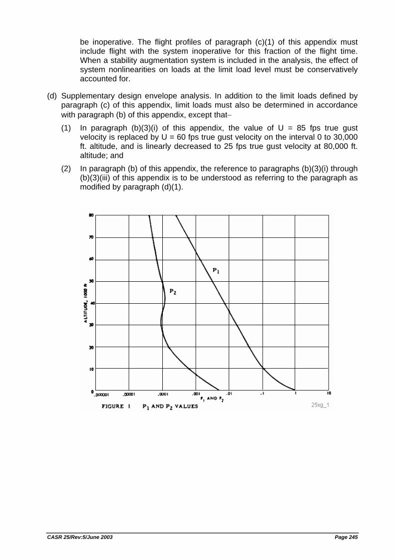
be inoperative. The flight profiles of paragraph (c)(1) of this appendix must include flight with the system inoperative for this fraction of the flight time. When a stability augmentation system is included in the analysis, the effect of system nonlinearities on loads at the limit load level must be conservatively accounted for.
(d) Supplementary design envelope analysis. In addition to the limit loads defined by paragraph (c) of this appendix, limit loads must also be determined in accordance with paragraph (b) of this appendix, except that− (1) In paragraph (b)(3)(i) of this appendix, the value of U = 85 fps true gust
velocity is replaced by U = 60 fps true gust velocity on the interval 0 to 30,000 ft. altitude, and is linearly decreased to 25 fps true gust velocity at 80,000 ft. altitude; and
(2) In paragraph (b) of this appendix, the reference to paragraphs (b)(3)(i) through (b)(3)(iii) of this appendix is to be understood as referring to the paragraph as modified by paragraph (d)(1).
CASR 25/Rev:5/June 2003 Page 245
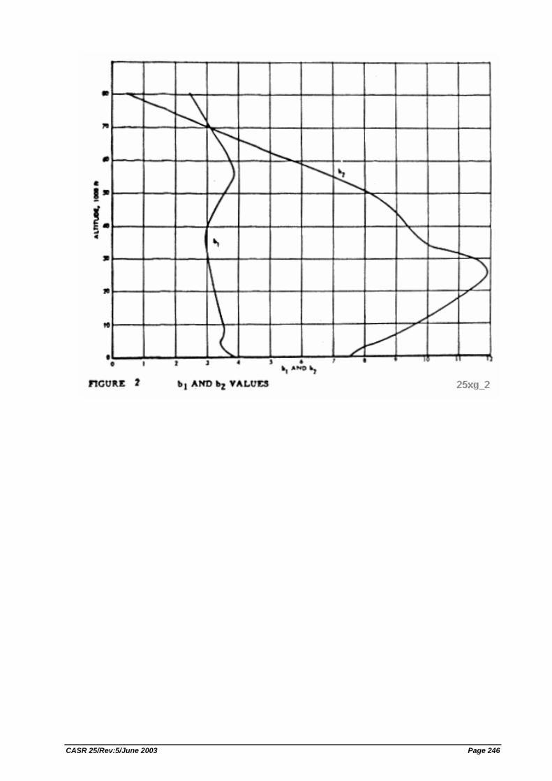
CASR 25/Rev:5/June 2003 Page 246
APPENDIX H - INSTRUCTIONS FOR CONTINUED AIRWORTHINESS
H25.1 General
(a) This appendix specifies requirements for the preparation of Instructions for Continued Airworthiness as required by Sec. 25.1529.
(b) Instructions for Continued Airworthiness for each airplane must include the Instructions for Continued Airworthiness for each engine and propeller (hereinafter designated "products"), for each appliance required by this Decree, and any required information relating to the interface of those appliances and products with the airplane. If Instructions for Continued Airworthiness are not supplied by the manufacturer of an appliance or product installed in the airplane, the Instructions for Continued Airworthiness for the airplane must include the information essential to the continued airworthiness of the airplane.
(c) The applicant must submit to the DGCA a program to show how changes to the Instructions for Continued Airworthiness made by the applicant or by the manufacturers or products and appliances installed in the airplane will be distributed.
H25.2 Format
(a) The Instructions for Continued Airworthiness must be in the form of a manual or manuals as appropriate for the quantity of data to be provided.
(b) The format of the manual or manuals must provide for a practical arrangement.
H25.3 Content
The contents of the manual or manuals must be prepared in the English language. The Instructions for Continued Airworthiness must contain the following manuals or sections, as appropriate, and information:
(a) Airplane maintenance manual or section. (1) Introduction information that includes an explanation of the airplane's features
and data to the extent necessary for maintenance or preventive maintenance. (2) A description of the airplane and its systems and installations including its
engines, propellers, and appliances. (3) Basic control and operation information describing how the airplane
components and systems are controlled and how they operate, including any special procedures and limitations that apply.
(4) Servicing information that covers details regarding servicing points, capacities of tanks, reservoirs, types of fluids to be used, pressures applicable to the various systems, location of access panels for inspection and servicing, locations of lubrication points, lubricants to be used, equipment required for servicing, tow instructions and limitations, mooring, jacking, and leveling information.
(b) Maintenance instructions.
CASR 25/Rev:5/June 2003 Page 247
(1) Scheduling information for each part of the airplane and its engines, auxiliary power units, propellers, accessories, instruments, and equipment that provides the recommended periods at which they should be cleaned, inspected, adjusted, tested, and lubricated, and the degree of inspection, the applicable wear tolerances, and work recommended at these periods. However, the applicant may refer to an accessory, instrument, or equipment manufacturer as the source of this information if the applicant shows that the item has an exceptionally high degree of complexity requiring specialized maintenance techniques, test equipment, or expertise. The recommended overhaul periods and necessary cross- references to the Airworthiness Limitations section of the manual must also be included. In addition, the applicant must include an inspection program that includes the frequency and extent of the inspections necessary to provide for the continued airworthiness of the airplane.
(2) Troubleshooting information describing probable malfunctions, how to recognize those malfunctions, and the remedial action for those malfunctions.
(3) Information describing the order and method of removing and replacing products and parts with any necessary precautions to be taken.
(4) Other general procedural instructions including procedures for system testing during ground running, symmetry checks, weighing and determining the center of gravity, lifting and shoring, and storage limitations.
(c) Diagrams of structural access plates and information needed to gain access for inspections when access plates are not provided.
(d) Details for the application of special inspection techniques including radiographic and ultrasonic testing where such processes are specified.
(e) Information needed to apply protective treatments to the structure after inspection.
(f) All data relative to structural fasteners such as identification, discard recommendations, and torque values.
(g) A list of special tools needed.
H25.4 Airworthiness Limitations Section
The Instructions for Continued Airworthiness must contain a section titled Airworthiness Limitations that is segregated and clearly distinguishable from the rest of the document. This section must set forth each mandatory replacement time, structural inspection interval, and related structural inspection procedure approved under Sec. 25.571. If the Instructions for Continued Airworthiness consist of multiple documents, the section required by this paragraph must be included in the principal manual. This section must contain a legible statement in a prominent location that reads: "The Airworthiness Limitations section is DGCA approved."
CASR 25/Rev:5/June 2003 Page 248
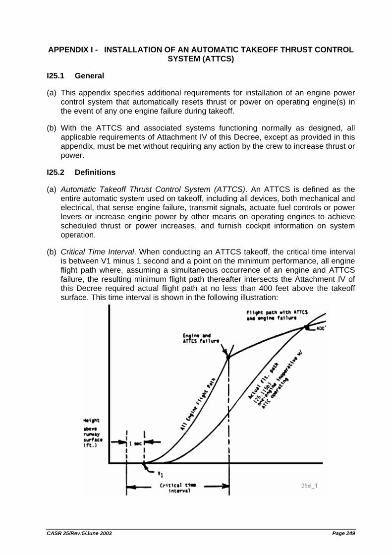
APPENDIX I - INSTALLATION OF AN AUTOMATIC TAKEOFF THRUST CONTROL SYSTEM (ATTCS)
I25.1 General
(a) This appendix specifies additional requirements for installation of an engine power control system that automatically resets thrust or power on operating engine(s) in the event of any one engine failure during takeoff.
(b) With the ATTCS and associated systems functioning normally as designed, all applicable requirements of Attachment IV of this Decree, except as provided in this appendix, must be met without requiring any action by the crew to increase thrust or power.
I25.2 Definitions
(a) Automatic Takeoff Thrust Control System (ATTCS). An ATTCS is defined as the entire automatic system used on takeoff, including all devices, both mechanical and electrical, that sense engine failure, transmit signals, actuate fuel controls or power levers or increase engine power by other means on operating engines to achieve scheduled thrust or power increases, and furnish cockpit information on system operation.
(b) Critical Time Interval. When conducting an ATTCS takeoff, the critical time interval is between V1 minus 1 second and a point on the minimum performance, all engine flight path where, assuming a simultaneous occurrence of an engine and ATTCS failure, the resulting minimum flight path thereafter intersects the Attachment IV of this Decree required actual flight path at no less than 400 feet above the takeoff surface. This time interval is shown in the following illustration:
CASR 25/Rev:5/June 2003 Page 249
I25.3 Performance and System Reliability Requirements
The applicant must comply with the performance and ATTCS reliability requirements as follows:
(a) An ATTCS failure or a combination of failures in the ATTCS during the critical time interval: (1) Shall not prevent the insertion of the maximum approved takeoff thrust or
power, or must be shown to be an improbable event. (2) Shall not result in a significant loss or reduction in thrust or power, or must be
shown to be an extremely improbable event.
(b) The concurrent existence of an ATTCS failure and an engine failure during the critical time interval must be shown to be extremely improbable.
(c) All applicable performance requirements of Attachment IV of this Decree must be met with an engine failure occurring at the most critical point during takeoff with the ATTCS system functioning.
I25.4 Thrust Setting
The initial takeoff thrust or power setting on each engine at the beginning of the takeoff roll may not be less than any of the following:
(a) Ninety (90) percent of the thrust or power set by the ATTCS (the maximum takeoff thrust or power approved for the airplane under existing ambient conditions);
(b) That required to permit normal operation of all safety related systems and equipment dependent upon engine thrust or power lever position; or
(c) That shown to be free of hazardous engine response characteristics when thrust or power is advanced from the initial takeoff thrust or power to the maximum approved takeoff thrust or power.
I25.5 Powerplant Controls
(a) In addition to the requirements of Sec. 25.1141, no single failure or malfunction, or probable combination thereof, of the ATTCS, including associated systems, may cause the failure of any powerplant function necessary for safety.
(b) The ATTCS must be designed to: (1) Apply thrust or power on the operating engine(s), following any one engine
failure during takeoff, to achieve the maximum approved takeoff thrust or power without exceeding engine operating limits;
(2) Permit manual decrease or increase in thrust or power up to the maximum takeoff thrust or power approved for the airplane under existing conditions through the use of the power lever. For airplanes equipped with limiters that automatically prevent engine operating limits from being exceeded under existing ambient conditions, other means may be used to increase the thrust or power in the event of an ATTCS failure provided the means is located on or forward of the power levers; is easily identified and operated under all operating conditions by a single action of either pilot with the hand that is
CASR 25/Rev:5/June 2003 Page 250
normally used to actuate the power levers; and meets the requirements of Sec. 25.777 (a), (b), and (c);
(3) Provide a means to verify to the flightcrew before takeoff that the ATTCS is in a condition to operate; and
(4) Provide a means for the flightcrew to deactivate the automatic function. This means must be designed to prevent inadvertent deactivation.
I25.6 Powerplant Instruments
In addition to the requirements of Sec. 25.1305:
(a) A means must be provided to indicate when the ATTCS is in the armed or ready condition; and
(b) If the inherent flight characteristics of the airplane do not provide adequate warning that an engine has failed, a warning system that is independent of the ATTCS must be provided to give the pilot a clear warning of any engine failure during takeoff.
CASR 25/Rev:5/June 2003 Page 251
APPENDIX J- EMERGENCY DEMONSTRATION
The following test criteria and procedures must be used for showing compliance with Sec. 25.803:
(a) The emergency evacuation must be conducted either during the dark of the night or during daylight with the dark of night simulated. If the demonstration is conducted indoors during daylight hours, it must be conducted with each window covered and each door closed to minimize the daylight effect. Illumination on the floor or ground may be used, but it must be kept low and shielded against shining into the airplane's windows or doors.
(b) The airplane must be in a normal attitude with landing gear extended.
(c) Unless the airplane is equipped with an off-wing descent means, stands or ramps may be used for descent from the wing to the ground. Safety equipment such as mats or inverted life rafts may be placed on the floor or ground to protect participants. No other equipment that is not part of the emergency evacuation equipment of the airplane may be used to aid the participants in reaching the ground.
(d) Except as provided in paragraph (a) of this Appendix, only the airplane's emergency lighting system may provide illumination.
(e) All emergency equipment required for the planned operation of the airplane must be installed.
(f) Each external door and exit, and each internal door or curtain, must be in the takeoff configuration.
(g) Each crewmember must be seated in the normally assigned seat for takeoff and must remain in the seat until receiving the signal for commencement of the demonstration. Each crewmember must be a person having knowledge of the operation of exits and emergency equipment.
(h) A representative passenger load of persons in normal health must be used as follows: (1) At least 40 percent of the passenger load must be female. (2) At least 35 percent of the passenger load must be over 50 years of age. (3) At least 15 percent of the passenger load must be female and over 50 years of
age. (4) Three life-size dolls, not included as part of the total passenger load, must be
carried by passengers to simulate live infants 2 years old or younger. (5) Crewmembers, mechanics, and training personnel, who maintain or operate
the airplane in the normal course of their duties, may not be used as passengers.
(i) No passengers may be assigned a specific seat except as the Director General may require. Except as required by subparagraph (g) of this paragraph, no employee of the applicant may be seated next to an emergency exit.
CASR 25/Rev:5/June 2003 Page 252
(j) Seat belts and shoulder harnesses (as required) must be fastened.
(k) Before the start of the demonstration, approximately one-half of the total average amount of carry-on baggage, blankets, pillows, and other similar articles must be distributed at several locations in aisles and emergency exit access ways to create minor obstructions.
(l) No prior indication may be given to any crewmember or passenger of the particular exits to be used in the demonstration.
(m) The applicant may not practice, rehearse, or describe the demonstration for the participants nor may any participant have taken part in this type of demonstration within the preceding 6 months.
(n) The pretakeoff passenger briefing required by operation rule may be given. The passengers may also be advised to follow directions of crewmembers but not be instructed on the procedures to be followed in the demonstration
(o) If safety equipment as allowed by paragraph (c) of this appendix is provided, either all passenger and cockpit windows must be blacked out or all of the emergency exits must have safety equipment in order to prevent disclosure of the available emergency exits.
(p) Not more than 50 percent of the emergency exits in the sides of the fuselage of an airplane that meets all of the requirements applicable to the required emergency exits for that airplane may be used for the demonstration. Exits that are not to be used in the demonstration must have the exit handle deactivated or must be indicated by red lights, red tape, or other acceptable means placed outside the exits to indicate fire or other reason why they are unusable. The exits to be used must be representative of all of the emergency exits on the airplane and must be designated by the applicant, subject to approval by the Director General. At least one floor-level exit must be used.
(q) Except as provided in paragraph (c) of this section, all evacuees must leave the airplane by a means provided as part of the airplane's equipment.
(r) The applicant's approved procedures must be fully utilized, except the flightcrew must take no active role in assisting others inside the cabin during the demonstration.
(s) The evacuation time period is completed when the last occupant has evacuated the airplane and is on the ground. Provided that the acceptance rate of the stand or ramp is no greater than the acceptance rate of the means available on the airplane for descent from the wing during an actual crash situation, evacuees using stands or ramps allowed by paragraph (c) of this Appendix are considered to be on the ground when they are on the stand or ramp. [Rev. 25-1, KM.7 Year 1996, 15 Feb. 1996; ref. FAR Amdt. 25-79]
CASR 25/Rev:5/June 2003 Page 253