Embed Size (px)
Citation preview
ww.sciencedirect.com
i n t e r n a t i o n a l j o u rn a l o f h y d r o g e n en e r g y 4 0 ( 2 0 1 5 ) 7 5e8 4
Available online at w
ScienceDirect
journal homepage: www.elsevier .com/locate/he
Direct steam reforming of diesel anddieselebiodiesel blends for distributed hydrogengeneration
Stefan Martin a,*, Gerard Kraaij a, Torsten Ascher a,Penelope Baltzopoulou b, George Karagiannakis b, David Wails c,Antje W€orner a
a German Aerospace Center (DLR), Institute of Technical Thermodynamics, Pfaffenwaldring 38e40, 70569 Stuttgart,
Germanyb Aerosol & Particle Technology Lab., Chemical Process & Energy Resources Inst., Centre for Research & Technology
Hellas (APTL/CPERI/CERTH), 6th km Charilaou-Thermi, P.O. Box: 60361, Thermi-Thessaloniki 57001, Greecec Johnson Matthey Technology Centre, Blount's Court Sonning Common, Reading RG4 9NH, United Kingdom
a r t i c l e i n f o
Article history:
Received 1 September 2014
Received in revised form
6 October 2014
Accepted 14 October 2014
Available online 6 November 2014
Keywords:
Hydrogen
Steam reforming
Diesel
Biodiesel
Liquid fuels
* Corresponding author. Tel.: þ49 711 6862 6E-mail address: [email protected] (S.
http://dx.doi.org/10.1016/j.ijhydene.2014.10.062
0360-3199/Copyright © 2014, The Authors. Publishe
CC BY-NC-ND license (http://creativecommons.org
a b s t r a c t
Distributed hydrogen generation from liquid fuels has attracted increasing attention in the
past years. Petroleum-derived fuels with already existing infrastructure benefit from high
volumetric and gravimetric energy densities, making them an interesting option for cost
competitive decentralized hydrogen production.
In the present study, direct steam reforming of diesel and diesel blends (7 vol.% bio-
diesel) is investigated at various operating conditions using a proprietary precious metal
catalyst. The experimental results show a detrimental effect of low catalyst inlet tem-
peratures and high feed mass flow rates on catalyst activity. Moreover, tests with a
desulfurized dieselebiodiesel blend indicate improved long-term performance of the
precious metal catalyst. By using deeply desulfurized diesel (1.6 ppmw sulfur), applying a
high catalyst inlet temperature (>800 �C), a high steam-to-carbon ratio (S/C ¼ 5) and a low
feed mass flow per open area of catalyst (11 g/h cm2), a stable product gas composition
close to chemical equilibrium was achieved over 100 h on stream. Catalyst deactivation
was not observed.
Copyright © 2014, The Authors. Published by Elsevier Ltd on behalf of Hydrogen Energy
Publications, LLC. This is an open access article under the CC BY-NC-ND license (http://
creativecommons.org/licenses/by-nc-nd/3.0/).
Introduction
The lack of an existing hydrogen production and distribution
infrastructure is widely considered an obstacle to an increased
deployment of stationary and mobile fuel cell systems in the
82; fax: þ49 711 6862 665Martin).
d by Elsevier Ltd on behalf of
/licenses/by-nc-nd/3.0/).
market [1e3]. In the transition phase towards sustainable
hydrogen production (for instance by making use of excess
wind energy and subsequent water electrolysis), it can be
reasonable to produce hydrogen from liquid fuels with readily
available infrastructure. Furthermore, liquid fuels offer the
advantage of high gravimetric and volumetric energy densities.
.
Hydrogen Energy Publications, LLC. This is an open access article under the
i n t e rn a t i o n a l j o u r n a l o f h y d r o g e n en e r g y 4 0 ( 2 0 1 5 ) 7 5e8 476
Today, the prevalent hydrogen production technology is
steam reforming of natural gas [4]. However, centralized
production suffers from additional hydrogen distribution
costs. In contrast, on-board hydrogen production from liquid
fuels for auxiliary power units (APUs) in heavy duty vehicles,
which generally is regarded as an important early market for
fuel cells in the transport sector [2], avoids the additional
distribution-related costs, but suffers from a high level of
system complexity. Therefore, several authors consider
distributed hydrogen generation (DHG) from liquid fuels
(diesel, biodiesel, methanol, ethanol etc.) to be a promising
mid-term option for hydrogen production [3,5e9]. Hulteberg
et al. [5] hypothesize that DHG systems will provide hydrogen
at the lowest cost by 2020. DHG is currently being investigated
in the framework of the FP7 project NEMESIS2þ. Within this
project a novel hydrogen generator (50 Nm3/h) based on diesel
and biodiesel is being developed for the purpose of integrating
it into an existing refueling station. Apart from integrating
such a system into refueling stations, on-site hydrogen gen-
eration from diesel is potentially applicable to the chemical
industry, in particular for blanketing, hydrogenation and
chemical synthesis.
Conversion of hydrocarbons into a hydrogen rich gas can
be achieved via partial oxidation (POX), autothermal reform-
ing (ATR) or steam reforming (SR). Among these three options,
SR is currently the most established hydrogen production
technology [10]. The product gas of SR is characterized by a
high partial pressure of hydrogen (70e80 vol.% on a dry basis)
compared to 40e50 vol.% for ATR and POX [11]. Drawbacks of
the SR technology are a poor dynamic behavior and a
comparatively high level of system complexity. Taking this
into account, SR is widely considered as the preferred
hydrogen production method for stationary applications
[4,12].
While successful pre-reforming of diesel in the low tem-
perature range (400e500 �C) using Ni-based catalysts has been
demonstrated by several working groups [13,3,14], direct SR of
diesel at high temperatures (~800 �C) is still at a relatively early
research and development stage and needs further improve-
ment [8]. Typically, diesel SR catalysts become deactivated
within a few hours of on-stream exposure [15], which is
mainly attributed to coking, sulfur poisoning and sintering of
the catalyst [16].
Ming et al. carried out SR of diesel surrogate hexadecane
using a proprietary catalyst formulation in a packed-bed
reactor. Stable catalyst performance was shown for 73 h on
stream without observing deactivation or carbon deposition
[17]. Goud et al. conducted SR of hexadecane using a Pd/ZrO2
catalyst coated on metal foils at steam-to-carbon ratios (S/C)
of 3e6 and T ¼ 750 �Ce850 �C. A first-order kinetic model with
a first-order deactivation rate was obtained. The catalyst
deactivation rate was found to be accelerated by the presence
of sulfur, at low S/C and at low temperatures [18].
In recent years, research groups have propagated the use of
microstructured reactors for SR of diesel-like fuels, thereby
circumventing problems related to heat and mass transfer
limitations. Thormann et al. investigated hexadecane SR over
a Rh/CeO2 catalyst using microstructured devices [19,20]. The
experiments revealed a fast transient response, thereby
making it an interesting option for mobile APU applications.
However, the reformer system suffered from high heat losses.
Kolb et al. [21] developed a microstructured plate heat
exchanger composed of stainless steel metal foils. Oxidative
diesel steam reforming (molar O/C-ratio: 0.12e0.2) was per-
formed using Euro V diesel supplied by Shell and using com-
mercial catalysts provided by Johnson Matthey. Although a
diesel conversion of 99.9% was achieved, formation of light
hydrocarbons started after only a few hours of operation at S/
C < 4 indicating the onset of catalyst deactivation. In a follow-
up study, Grote et al. [22] carried out further steam reforming
tests (4e10 kW thermal input) using a diesel surrogate
mixture, accompanied by computational fluid dynamics
modeling. The results show an increase of residual hydro-
carbons (caused by deactivation of catalyst activity) with
decreasing temperature. In order to prevent the formation of
higher hydrocarbons, a reformer outlet temperature in excess
of 1013 K was required. Long-term performance data was not
presented by the authors. In a second follow-up study, Max-
imini et al. [23] tested four downscaled microchannel diesel
steam reformers (1 kWth) with different precious metal coat-
ings at S/C ratios of 3 and 4. Increased carbon formation was
observed when reducing the temperature from 800 �C to
700 �C. This was accompanied by the formation of higher
hydrocarbons like C2H4, C2H2 and C3H6. The same group of
authors presented experimental results of a microstructured
diesel SR fuel processor coupled with a PEM fuel cell [24]. The
10 kWth reformer consisted of 35 reformer channels with a
channel height of 0.6 mm and 34 combustion channels being
operated at S/C ¼ 5 and 6 and a reactor outlet temperature of
765e800 �C. The results indicated a clear trend toward
increasing residual hydrocarbon formation for higher feed
mass flow rates. Furthermore, the stack voltage was observed
to be highly sensitive to the residual hydrocarbon concentra-
tion in the reformate gas.
Other research groups used Ni-based catalysts for SR of
diesel as Nickel is less expensive and more readily available
than precious metals [6,15,25e27]. Fauteux-Lefebvre et al. [6]
tested an Al2O3eZrO2-supported nickelealumina spinel cata-
lyst in a lab-scale isothermal packed-bed reactor at various
operating conditions. Mixing of fuel and water was achieved
by feeding in a stabilized hydrocarbon-water emulsion, which
successfully prevented undesired pre-cracking. Product con-
centrations close to equilibrium for up to 20 h on-stream
exposure were reported at severe operating conditions
(T < 720 �C, S/C < 2.5). Steam reforming of commercial diesel
was carried out for more than 15 h at S/C < 2. Carbon forma-
tion on the catalyst surface was not observed, although
measured diesel conversion was lower than 90% [15].
Boon et al. were the first to report stable diesel steam
reforming at temperatures of 800 �C using commercial
preciousmetal catalysts [3]. The experiments were carried out
in a packed-bed reactor at low gas hourly space velocities
(GHSV) of 1000e2000 h�1. Diesel evaporation was achieved by
spraying diesel in a hot gas phase, thereby preventing self-
pyrolysis during the evaporation step. Stable conditions with
no sign of deactivation were reported for 143 h on stream at
1.2 bar, 800 �C and S/C ¼ 4.6 and 2.6 using Aral Ultimate diesel
with an added 6.5 ppm sulfur. Similar experiments with
commercial BP Ultimate diesel containing 6 ppm sulfur turned
out to be more challenging due to problems with blocking of
i n t e r n a t i o n a l j o u rn a l o f h y d r o g e n en e r g y 4 0 ( 2 0 1 5 ) 7 5e8 4 77
the diesel capillary and the nozzle. By using a medium sized
diesel capillary (0.25 mm internal diameter) continuous
operation was achieved for 180 h without observing any sign
of deactivation, although deactivation occurred at larger di-
ameters. The authors concluded that the observed deactiva-
tion was caused by the poor spraying of diesel, resulting in
fluctuations of diesel conversion, thus initiating coke
deposition.
The objective of this paper is to evaluate the applicability of
direct steam reforming of diesel and dieselebiodiesel blends
at various operating conditions using a proprietary precious
metal based catalyst. The experimental study includes varia-
tion of reformer temperature, feed mass flow rate and diesel
sulfur content. Special emphasis is placed on evaluating
catalyst deactivation induced by coking and sulfur poisoning.
Suitable operating conditions for stable steam reforming of
diesel are determined, thus avoiding catalyst deactivation.
The present study demonstrates the feasibility of direct high
temperature steam reforming at elevated pressures, which
advances the state of the art in this field.
Methodology
Diesel properties and chemical reaction system
Diesel is a complex mixture of paraffins, olefins, cycloalkanes
and aromatics, containing up to 400 different hydrocarbon
species, including organic sulfur compounds and additives
[28]. Different empirical chemical formulae have been re-
ported in the literature: C12H20 [15], C14.342H24.75O0.0495 [29],
C13.4H26.3 [30], C13.57H27.14 [31], C16.2H30.6 [32]. In the present
study, a Shell diesel fulfilling EN 590 is used with the main
properties given in Table 1. Based on the chemical analysis an
empirical formula of C13.3H24.7 and a molecular weight of
185 g/mol was derived.
Steam reforming of diesel can be described by three inde-
pendent equations, namely the conversion of hydrocarbons
into carbon monoxide and hydrogen (Eq. (1)), the wateregas
shift (WGS) reaction (Eq. (2)) and themethanation reaction (Eq.
(3)). While the WGS and the methanation reactions are
exothermic being favored at low temperatures, the diesel
steam reforming reaction is endothermic, thus requiring
external heat supply. Thermodynamics dictate that a high
hydrogen yield is favored at high temperatures, high S/C and
low pressures.
Table 1 e Diesel properties.
Property Value Test method
Density at T ¼ 15 �C (kg/m3) 836.4 ASTM D4052-11/ISO
12185-96
Lower heating value
LHV (MJ/kg)
42.93 DIN 51,900-1,3
Monoaromatics (wt.%) 21.5 EN 12916
Polyaromatics (wt.%) 2.5 EN 12916
Total aromatic
content (wt.%)
24.0 EN 12916
Sulfur content (ppmw) 7.0 ASTM D4294/EN 20884
CnHm þ nH2O / nCO þ (n þ m/2) H2 DH298 K z þ150 kJ/mol(1)
CO þ H2O 4 H2 þ CO2 DH298 K ¼ �41 kJ/mol (2)
CO þ 3H2 4 CH4 þ H2O DH298 K ¼ �206 kJ/mol (3)
The exact mechanism of diesel steam reforming is not
completely understood. However, it is generally agreed that
steam reforming of higher hydrocarbons takes place by irre-
versible adsorption on the catalyst surface resulting in C1
compounds, followed by a surface reaction mechanism for
conversion of C1 species to yield gaseous CO [33,19]. CO is then
converted to CO2 through WGS reaction. The methanation re-
action takes place simultaneously. Apart from the main SR re-
actions, undesired coking can occur (Eqs. (4e8)), leading to a
gradual blocking of the active sites and subsequent catalyst
deactivation. Elemental carbon can be formed directly from
higher hydrocarbons (Eq. (4)), carbonmonoxide (Eqs. (5) and (6))
andmethane (Eq. (7)), or via polymerizationofolefins/aromatics
and subsequent stepwise dehydrogenation (Eq. (8)) [33]. The
extent of the coking reactions strongly depends on reformer
operating conditions such as temperature, steam-to-carbon
ratio, gas hourly space velocity and reaction kinetics [34].
CnHm / C þ H2 þ CH4 þ … DH298 K � 0 kJ/mol (4)
2CO 4 C þ CO2 DH298 K ¼ �172 kJ/mol (5)
CO þ H2 4 C þ H2O DH298 K ¼ �131 kJ/mol (6)
CH4 4 C þ 2H2 DH298 K ¼ þ75 kJ/mol (7)
Olefines, Aromatics / Polymers / Coke
DH298 K � 0 kJ/mol (8)
It is well known that the catalysts used for diesel reforming
are prone to deactivation by sulfur poisoning [35]. The main
sulfur compounds in logistic fuels are mercaptanes, sul-
phides, disulphides, thiophenes, benzothiophenes (BT) and
dibenzothiophenes (DBT). The prevailing sulfur species in
commercial diesel are BTs and DBTs. Although the mecha-
nism of sulfur poisoning of metallic catalysts is not fully un-
derstood, it is assumed that metal poisoning by sulfur
compounds involves strong chemisorption of the sulfur-
containing molecule on the metal sites (Eq. (9)), leading to a
stable and inactive metal sulfide species on the catalyst sur-
face (Eq. (10)) [33]. In contrast to catalyst coking, sulfur
poisoning is very difficult to reverse, requiring harsh condi-
tions for catalyst regeneration [15].
M þ S � R / M þ R0 þ H2S (9)
H2S þ M / M � S þ H2 (10)
i n t e rn a t i o n a l j o u r n a l o f h y d r o g e n en e r g y 4 0 ( 2 0 1 5 ) 7 5e8 478
Experimental test set-up
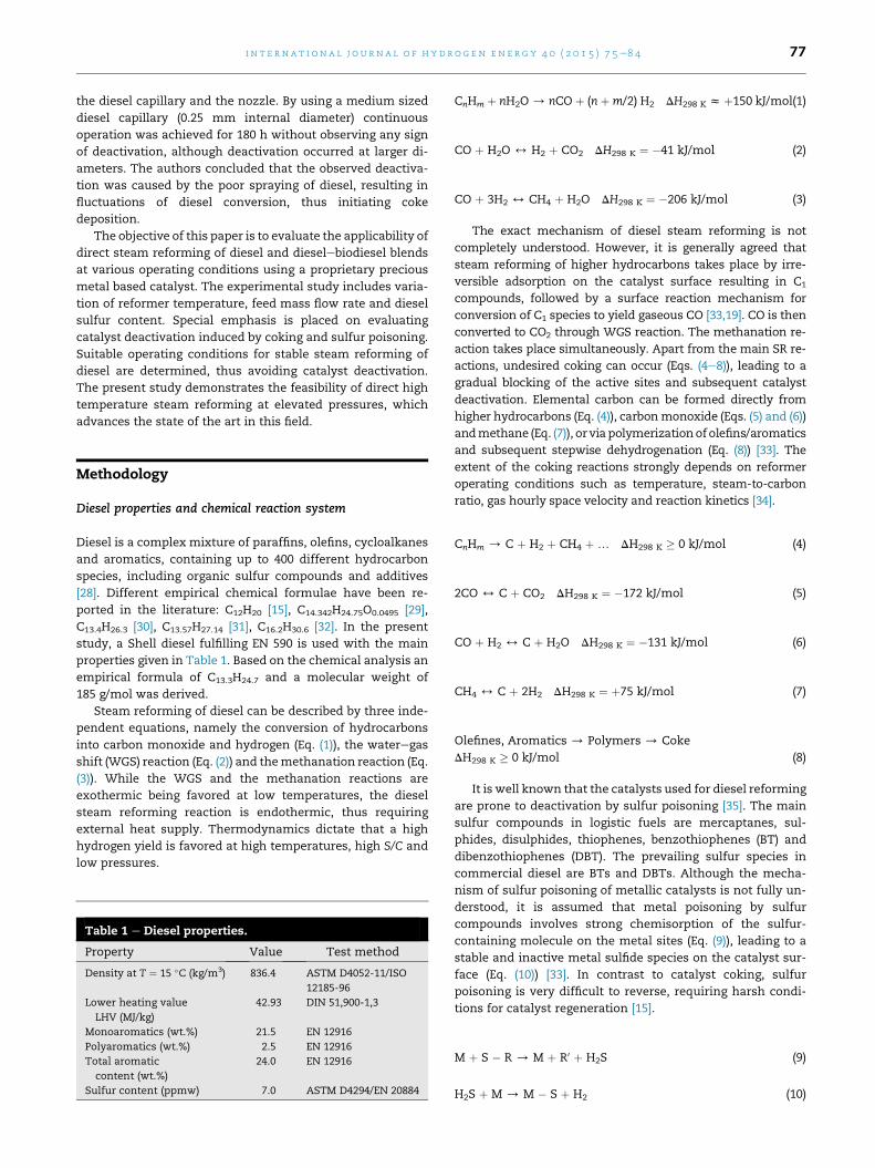
The flow sheet and the main components of the test-rig
employed in the present study are shown in Fig. 1. Water
and diesel are fed into the reformer using mass flow control-
lers andmicro annular gear pumps. Diesel at T ¼ 0 �C is mixed
with superheated steam (T¼ 390 �C) before being heated by an
electrical oven to the desired SR temperature. The catalytic
conversion into H2, CO, CO2 and CH4 is accomplished by using
a metal-based catalyst monolith which is mounted inside a
stainless steel tube (d ¼ 2.1 cm). The catalyst monolith
(600 cpsi, l ¼ 5.1 cm, d ¼ 2.03 cm) is coated with finely
distributed platinum groupmetals. The catalyst comprised Rh
on a high surface area (140 m2/g), alumina based mixed metal
oxide support. It was coated onto the monolith at a loading of
0.122 g catalyst/cm3 with an overall Rh loading of 2440 g/m3.
The reformer temperature is controlled via the catalyst outlet
temperature TD.
Nickel alloy thermocouples (type k) have been used in this
studywith a specifiedmeasurement error of ±2.5 K. By placing
four thermocouples along the axis of the catalyst piece (TA,
TB, TC, TD, see Fig. 1), the temperature profile can be
measured over time on stream. The axial temperature profile
provides valuable information on catalyst activity. After
initiation of the reforming reaction, the temperature at the
catalyst inlet drops due to the endothermic heat demand of
the SR reaction. A stable catalyst inlet temperature over time
indicates stable catalyst activity, whereas a temperature in-
crease is accompanied by a loss of catalyst activity.
Upon leaving the reformer section, water and unconverted
diesel are condensed in a cold trap at T ¼ 10 �C and stored in a
condensate reservoir. Before each experiment, the cold trap is
filled with 100 ml of organic solvent (dodecane, mixture of
isomers). The fuel conversion rate FCR, (Eq. (11)) is subse-
quently derived from gas chromatography (GC) analysis of the
organic phase that accumulates in the cold trap during the
test. GC analysis of the condensate was found to be more
reliable than determining the fuel conversion via the gas
phase. In addition, carbon deposition on the catalyst surface
and the tube walls and higher hydrocarbons leaving the cold
trap are considered for FCR calculations:
Fig. 1 e Schematic of diesel s
FCR ¼ mD � �mD;liq: þmC þmHCs
�mD
(11)
The amount of condensed diesel and its cracking products
in the cold trapmD;liq: is derived from the area proportion xD;liq:
in the gas chromatogram (which is assumed to be equivalent
to the mass proportion) and the amount of dodecane mDod
according to Eq. (12). The amount of deposited carbon mC is
obtained by flushing the system with air after each test and
detecting the resulting CO2 evolution. Higher hydrocarbons
mHCs (C2eC4) passing the cold trap are measured periodically
via GC analysis (Varian Micro CP-4900, accuracy: ±0.1% of the
upper limit range).
mD;liq: ¼ mDod,
�1
1� xD;liq:� 1
�(12)
Downstream of the cold trap, any remaining moisture is
removed by an aerosol filter. The dry reformate gas flow is
measured with a mass flow controller before it enters the
online gas analyzer unit (Rosemount Analytical NGA 2000
MLT), which is equipped with an infrared adsorption detector
for CO, CO2 and CH4 and a thermal conductivity detector for
measurement of H2. The specified measurement error is ±1%relative to the full scale value.
Accordingly, the mass balance of the process is given by:
mdiesel þmwater ¼ mcondensate þmmoisture;residual þmreformate;dry
A mass balance error (defined as��1�mproduct=mfeed
��) of <2%was determined for all SR experiments presented in this study.
Parameters
The gas hourly space velocity GHSV at standard temperature
and pressure (STP) and the molar steam-to-carbon ratio S/C
are defined as follows:
GHSV ¼_VFeed;STP
Vcat:(13)
S�C ¼ _nH2O
_nDiesel;C(14)
team reforming test rig.
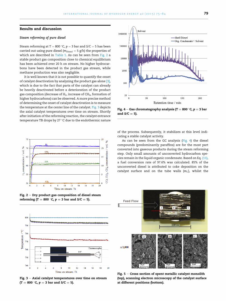
Fig. 4 e Gas chromatography analysis (T¼ 800 �C, p¼ 3 bar
and S/C ¼ 5).
i n t e r n a t i o n a l j o u rn a l o f h y d r o g e n en e r g y 4 0 ( 2 0 1 5 ) 7 5e8 4 79
Results and discussion
Steam reforming of pure diesel
Steam reforming at T ¼ 800 �C, p ¼ 3 bar and S/C ¼ 5 has been
carried out using pure diesel (mDiesel ¼ 5 g/h) the properties of
which are described in Table 1. As can be seen from Fig. 2 a
stable product gas composition close to chemical equilibrium
has been achieved over 20 h on stream. No higher hydrocar-
bons have been detected in the product gas stream, while
methane production was also negligible.
It is well known that it is not possible to quantify the onset
of catalyst deactivation by analyzing the product gas alone [3],
which is due to the fact that parts of the catalyst can already
be heavily deactivated before a deterioration of the product
gas composition (decrease of H2, increase of CH4, formation of
higher hydrocarbons) can be observed. Amore precisemethod
of determining the onset of catalyst deactivation is tomeasure
the temperature at the center line of the catalyst. Fig. 3 depicts
the axial catalyst temperatures over time on stream. Shortly
after initiation of the reforming reaction, the catalyst entrance
temperature TB drops by 27 �C due to the endothermic nature
Fig. 2 e Dry product gas composition of diesel steam
reforming (T ¼ 800 �C, p ¼ 3 bar and S/C ¼ 5).
Fig. 3 e Axial catalyst temperatures over time on stream
(T ¼ 800 �C, p ¼ 3 bar and S/C ¼ 5).
of the process. Subsequently, it stabilizes at this level indi-
cating a stable catalyst activity.
As can be seen from the GC analysis (Fig. 4) the diesel
compounds (predominantly paraffins) are for the most part
converted into gaseous products during the steam reforming
step. Only small amounts of unconverted hydrocarbon spe-
cies remain in the liquid organic condensate. Based on Eq. (11),
a fuel conversion rate of 97.6% was calculated. 85% of the
unconverted diesel is attributed to coke deposition on the
catalyst surface and on the tube walls (mC), whilst the
Fig. 5 e Cross section of spent metallic catalyst monolith
(top), scanning electron microscopy of the catalyst surface
at different positions (bottom).
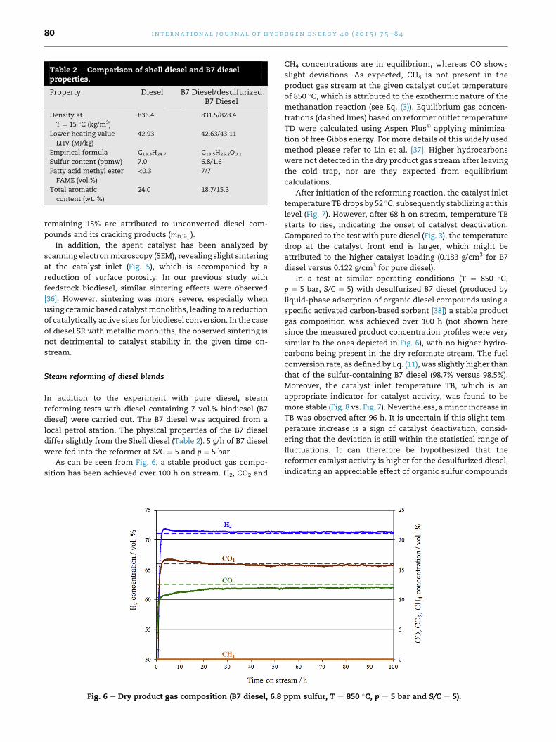
Table 2 e Comparison of shell diesel and B7 dieselproperties.
Property Diesel B7 Diesel/desulfurizedB7 Diesel
Density at
T ¼ 15 �C (kg/m3)
836.4 831.5/828.4
Lower heating value
LHV (MJ/kg)
42.93 42.63/43.11
Empirical formula C13.3H24.7 C13.5H25.2O0.1
Sulfur content (ppmw) 7.0 6.8/1.6
Fatty acid methyl ester
FAME (vol.%)
<0.3 7/7
Total aromatic
content (wt. %)
24.0 18.7/15.3
i n t e rn a t i o n a l j o u r n a l o f h y d r o g e n en e r g y 4 0 ( 2 0 1 5 ) 7 5e8 480
remaining 15% are attributed to unconverted diesel com-
pounds and its cracking products (mD;liq:).
In addition, the spent catalyst has been analyzed by
scanning electronmicroscopy (SEM), revealing slight sintering
at the catalyst inlet (Fig. 5), which is accompanied by a
reduction of surface porosity. In our previous study with
feedstock biodiesel, similar sintering effects were observed
[36]. However, sintering was more severe, especially when
using ceramic based catalystmonoliths, leading to a reduction
of catalytically active sites for biodiesel conversion. In the case
of diesel SR with metallic monoliths, the observed sintering is
not detrimental to catalyst stability in the given time on-
stream.
Steam reforming of diesel blends
In addition to the experiment with pure diesel, steam
reforming tests with diesel containing 7 vol.% biodiesel (B7
diesel) were carried out. The B7 diesel was acquired from a
local petrol station. The physical properties of the B7 diesel
differ slightly from the Shell diesel (Table 2). 5 g/h of B7 diesel
were fed into the reformer at S/C ¼ 5 and p ¼ 5 bar.
As can be seen from Fig. 6, a stable product gas compo-
sition has been achieved over 100 h on stream. H2, CO2 and
Fig. 6 e Dry product gas composition (B7 diesel, 6.8
CH4 concentrations are in equilibrium, whereas CO shows
slight deviations. As expected, CH4 is not present in the
product gas stream at the given catalyst outlet temperature
of 850 �C, which is attributed to the exothermic nature of the
methanation reaction (see Eq. (3)). Equilibrium gas concen-
trations (dashed lines) based on reformer outlet temperature
TD were calculated using Aspen Plus® applying minimiza-
tion of free Gibbs energy. For more details of this widely used
method please refer to Lin et al. [37]. Higher hydrocarbons
were not detected in the dry product gas stream after leaving
the cold trap, nor are they expected from equilibrium
calculations.
After initiation of the reforming reaction, the catalyst inlet
temperature TB drops by 52 �C, subsequently stabilizing at this
level (Fig. 7). However, after 68 h on stream, temperature TB
starts to rise, indicating the onset of catalyst deactivation.
Compared to the test with pure diesel (Fig. 3), the temperature
drop at the catalyst front end is larger, which might be
attributed to the higher catalyst loading (0.183 g/cm3 for B7
diesel versus 0.122 g/cm3 for pure diesel).
In a test at similar operating conditions (T ¼ 850 �C,p ¼ 5 bar, S/C ¼ 5) with desulfurized B7 diesel (produced by
liquid-phase adsorption of organic diesel compounds using a
specific activated carbon-based sorbent [38]) a stable product
gas composition was achieved over 100 h (not shown here
since the measured product concentration profiles were very
similar to the ones depicted in Fig. 6), with no higher hydro-
carbons being present in the dry reformate stream. The fuel
conversion rate, as defined by Eq. (11), was slightly higher than
that of the sulfur-containing B7 diesel (98.7% versus 98.5%).
Moreover, the catalyst inlet temperature TB, which is an
appropriate indicator for catalyst activity, was found to be
more stable (Fig. 8 vs. Fig. 7). Nevertheless, a minor increase in
TB was observed after 96 h. It is uncertain if this slight tem-
perature increase is a sign of catalyst deactivation, consid-
ering that the deviation is still within the statistical range of
fluctuations. It can therefore be hypothesized that the
reformer catalyst activity is higher for the desulfurized diesel,
indicating an appreciable effect of organic sulfur compounds
ppm sulfur, T ¼ 850 �C, p ¼ 5 bar and S/C ¼ 5).
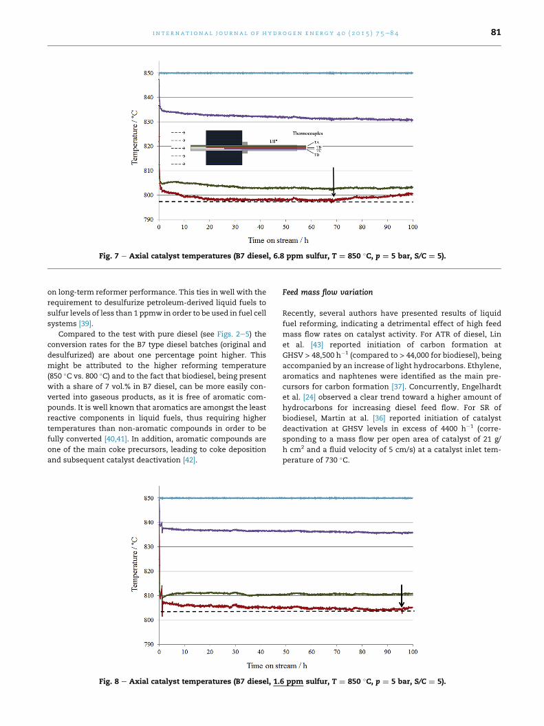
Fig. 7 e Axial catalyst temperatures (B7 diesel, 6.8 ppm sulfur, T ¼ 850 �C, p ¼ 5 bar, S/C ¼ 5).
i n t e r n a t i o n a l j o u rn a l o f h y d r o g e n en e r g y 4 0 ( 2 0 1 5 ) 7 5e8 4 81
on long-term reformer performance. This ties in well with the
requirement to desulfurize petroleum-derived liquid fuels to
sulfur levels of less than 1 ppmw in order to be used in fuel cell
systems [39].
Compared to the test with pure diesel (see Figs. 2e5) the
conversion rates for the B7 type diesel batches (original and
desulfurized) are about one percentage point higher. This
might be attributed to the higher reforming temperature
(850 �C vs. 800 �C) and to the fact that biodiesel, being present
with a share of 7 vol.% in B7 diesel, can be more easily con-
verted into gaseous products, as it is free of aromatic com-
pounds. It is well known that aromatics are amongst the least
reactive components in liquid fuels, thus requiring higher
temperatures than non-aromatic compounds in order to be
fully converted [40,41]. In addition, aromatic compounds are
one of the main coke precursors, leading to coke deposition
and subsequent catalyst deactivation [42].
Fig. 8 e Axial catalyst temperatures (B7 diesel, 1.6
Feed mass flow variation
Recently, several authors have presented results of liquid
fuel reforming, indicating a detrimental effect of high feed
mass flow rates on catalyst activity. For ATR of diesel, Lin
et al. [43] reported initiation of carbon formation at
GHSV > 48,500 h�1 (compared to > 44,000 for biodiesel), being
accompanied by an increase of light hydrocarbons. Ethylene,
aromatics and naphtenes were identified as the main pre-
cursors for carbon formation [37]. Concurrently, Engelhardt
et al. [24] observed a clear trend toward a higher amount of
hydrocarbons for increasing diesel feed flow. For SR of
biodiesel, Martin at al. [36] reported initiation of catalyst
deactivation at GHSV levels in excess of 4400 h�1 (corre-
sponding to a mass flow per open area of catalyst of 21 g/
h cm2 and a fluid velocity of 5 cm/s) at a catalyst inlet tem-
perature of 730 �C.
ppm sulfur, T ¼ 850 �C, p ¼ 5 bar, S/C ¼ 5).
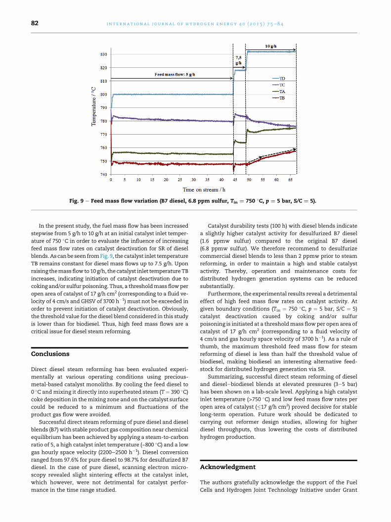
Fig. 9 e Feed mass flow variation (B7 diesel, 6.8 ppm sulfur, Tin ¼ 750 �C, p ¼ 5 bar, S/C ¼ 5).
i n t e rn a t i o n a l j o u r n a l o f h y d r o g e n en e r g y 4 0 ( 2 0 1 5 ) 7 5e8 482
In the present study, the fuel mass flow has been increased
stepwise from 5 g/h to 10 g/h at an initial catalyst inlet temper-
ature of 750 �C in order to evaluate the influence of increasing
feed mass flow rates on catalyst deactivation for SR of diesel
blends.Ascanbe seen fromFig. 9, the catalyst inlet temperature
TB remains constant for diesel mass flows up to 7.5 g/h. Upon
raising themassflowto10g/h, the catalyst inlet temperatureTB
increases, indicating initiation of catalyst deactivation due to
coking and/or sulfur poisoning. Thus, a thresholdmass flowper
open area of catalyst of 17 g/h cm2 (corresponding to a fluid ve-
locity of 4 cm/s and GHSV of 3700 h�1) must not be exceeded in
order to prevent initiation of catalyst deactivation. Obviously,
the threshold value for the diesel blend considered in this study
is lower than for biodiesel. Thus, high feed mass flows are a
critical issue for diesel steam reforming.
Conclusions
Direct diesel steam reforming has been evaluated experi-
mentally at various operating conditions using precious-
metal-based catalyst monoliths. By cooling the feed diesel to
0 �C andmixing it directly into superheated steam (T ¼ 390 �C)coke deposition in themixing zone and on the catalyst surface
could be reduced to a minimum and fluctuations of the
product gas flow were avoided.
Successful direct steam reforming of pure diesel and diesel
blends (B7) with stable product gas composition near chemical
equilibrium has been achieved by applying a steam-to-carbon
ratio of 5, a high catalyst inlet temperature (~800 �C) and a low
gas hourly space velocity (2200e2500 h�1). Diesel conversion
ranged from 97.6% for pure diesel to 98.7% for desulfurized B7
diesel. In the case of pure diesel, scanning electron micro-
scopy revealed slight sintering effects at the catalyst inlet,
which however, were not detrimental for catalyst perfor-
mance in the time range studied.
Catalyst durability tests (100 h) with diesel blends indicate
a slightly higher catalyst activity for desulfurized B7 diesel
(1.6 ppmw sulfur) compared to the original B7 diesel
(6.8 ppmw sulfur). We therefore recommend to desulfurize
commercial diesel blends to less than 2 ppmw prior to steam
reforming, in order to maintain a high and stable catalyst
activity. Thereby, operation and maintenance costs for
distributed hydrogen generation systems can be reduced
substantially.
Furthermore, the experimental results reveal a detrimental
effect of high feed mass flow rates on catalyst activity. At
given boundary conditions (Tin ¼ 750 �C, p ¼ 5 bar, S/C ¼ 5)
catalyst deactivation caused by coking and/or sulfur
poisoning is initiated at a thresholdmass flowper open area of
catalyst of 17 g/h cm2 (corresponding to a fluid velocity of
4 cm/s and gas hourly space velocity of 3700 h�1). As a rule of
thumb, the maximum threshold feed mass flow for steam
reforming of diesel is less than half the threshold value of
biodiesel, making biodiesel an interesting alternative feed-
stock for distributed hydrogen generation via SR.
Summarizing, successful direct steam reforming of diesel
and dieselebiodiesel blends at elevated pressures (3e5 bar)
has been shown on a lab-scale level. Applying a high catalyst
inlet temperature (>750 �C) and low feed mass flow rates per
open area of catalyst (�17 g/h cm2) proved decisive for stable
long-term operation. Future work should be dedicated to
carrying out reformer design studies, allowing for higher
diesel throughputs, thus lowering the costs of distributed
hydrogen production.
Acknowledgment
The authors gratefully acknowledge the support of the Fuel
Cells and Hydrogen Joint Technology Initiative under Grant
i n t e r n a t i o n a l j o u rn a l o f h y d r o g e n en e r g y 4 0 ( 2 0 1 5 ) 7 5e8 4 83
Agreement No. 278138. The HIFUEL precious metal catalysts
used in this study were kindly provided by Johnson Matthey.
The desulfurized diesel was provided by the Aerosol and
Particle Technology Laboratory of the Centre for Research and
Technology Hellas (APTL/CERTH). The biodiesel was supplied
by Abengoa Bioenergy. For proofreading the manuscript we
thank Martin Kraenzel.
r e f e r e n c e s
[1] Pettersson LJ, Westerholm R. State of the art of multi-fuelreformers for fuel cell vehicles: problem identification andresearch needs. Int J Hydrogen Energy 2001;26:243e64.
[2] Contestabile M. Analysis of the market for diesel PEM fuelcell auxiliary power units onboard long-haul trucks and of itsimplications for the large-scale adoption of PEMFCs. EnergyPolicy 2010;38:5320e34.
[3] Boon J, van Dijk E, de Munck S, van den Brink R. Steamreforming of commercial ultra-low sulphur diesel. J PowerSources 2011;196:5928e35.
[4] Holladay JD, Hu J, King DL, Wang Y. An overview of hydrogenproduction technologies. Catal Today 2009;139:244e60.
[5] Hulteberg PC, Burford H, Duraiswamy K, Porter B, Woods R. Acost effective steam reformer for a distributed hydrogeninfrastructure. Int J Hydrogen Energy 2008;33:1266e74.
[6] Fauteux-Lefebvre C, Abatzoglou N, Blanchard J,Gitzhofer F. Steam reforming of liquid hydrocarbons overa nickel-alumina spinel catalyst. J Power Sources2010;195:3275e83.
[7] Levin DB, Chahine R. Challenges for renewable hydrogenproduction from biomass. Int J Hydrogen Energy2010;35:4962e9.
[8] Specchia S. Fuel processing activities at European level: apanoramic overview. Int J Hydrogen Energy2014;39:17953e68.
[9] Nahar G, Dupont V. Recent advances in hydrogenproduction via autothermal reforming process (ATR): areview of patents and research articles. Recent Pat ChemEng 2013;6:8e42.
[10] Nahar G, Dupont V. Hydrogen via steam reforming of liquidbiofeedstock. Biofuels 2012;3(2):167e91.
[11] Ersoz A, Olgun H, Ozdogan S. Reforming options forhydrogen production from fossil fuels for PEM fuel cells. JPower Sources 2006;154:67e73.
[12] Martin S, W€orner A. On-board reforming of biodiesel andbioethanol for high temperature PEM fuel cells: comparisonof autothermal reforming and steam reforming. J PowerSources 2011;196(6):3163e71.
[13] Piwetz MM, Larsen JS, Christensen TS. Hydrodesulfurizationand prereforming of logistic fuels for use in fuel cellapplications, fuel cell seminar program and abstracts. 1996.
[14] Koo KY, Park MG, Jung UH, Kim SH, Yoon WL. Diesel pre-reforming over highly dispersed nano-sized Ni catalystssupported on MgOeAl2O3 mixed oxides. Int J HydrogenEnergy 2014;39:10941e50.
[15] Fauteux-Lefebvre C, Abatzoglou N, Braidy N, Achouri IE.Diesel steam reforming with a nickel-alumina spinel catalystfor solid oxide fuel cell application. J Power Sources2011;196:7673e80.
[16] Bartholomew CH, Farrauto RJ. Fundamentals of industrialcatalytic processes. 2nd ed. Wiley; 2006.
[17] Ming Q, Healey T, Allen L, Irving P. Steam reforming ofhydrocarbon fuels. Catal Today 2002;77:51e64.
[18] Goud SK, Whittenberger WA, Chattopadhyay S,Abraham MA. Steam reforming of n-hexadecane using a Pd/
ZrO2 catalyst: kinetics of catalyst deactivation. Int J HydrogenEnergy 2007;32:2868e74.
[19] Thormann J, Maier L, Pfeifer P, Kunz U, Deutschmann O,Schubert K. Steam reforming of hexadecane over a Rh/CeO2 catalyst in microchannels: experimental and numericalinvestigation. Int J Hydrogen Energy 2009;34:5108e20.
[20] Thormann J, Pfeifer P, Kunz U. Dynamic performance ofhexadecane steam reforming in a microstructured reactor.Chem Eng J 2012;191:410e5.
[21] Kolb G, Hofmann C, O'Connell M, Schurer J. Microstructuredreactors for diesel steam reforming, wateregas shift andpreferential oxidation in the kiloWatt power range. CatalToday 2009;147S:S176e84.
[22] Grote M, Maximini M, Yang Z, Engelhardt P, K€ohne H,Lucka K, et al. Experimental and computationalinvestigations of a compact steam reformer for fuel oil anddiesel fuel. J Power Sources 2011;196:9027e35.
[23] Maximini M, Engelhardt P, Grote M, Brenner M. Furtherdevelopment of a microchannel steam reformer for dieselfuel. Int J Hydrogen Energy 2012;37:10125e34.
[24] Engelhardt P,MaximiniM, BeckmannF, BrennerM. Integratedfuel cell APU based on a compact steam reformer for dieseland a PEMFC. Int J Hydrogen Energy 2012;37:13470e7.
[25] Achouri IE, Abatzoglou N, Fauteux-Lefebvre C, Braidy N.Diesel steam reforming: comparison of two nickel aluminatecatalysts prepared by wet-impregnation and co-precipitation. Catal Today 2013;207:13e20.
[26] Xu L, Mi W, Su Q. Hydrogen production through diesel steamreforming over rare-earth promoted Ni/g-Al2O3 catalysts. JNat Gas Chem 2011;20:287e93.
[27] Zyryanova MM, Badmaev SD, Belyaev VD, Amosov YI,Snytnikov PV, Kirillov VA, et al. Catalytic reforming ofhydrocarbon feedstocks into fuel for power generation units.Catal Oil Ref 2013;5:312e7.
[28] Parmar RD, Kundu A, Karan K. Thermodynamic analysis ofdiesel reforming process: mapping of carbon formationboundary and representative independent reactions. J PowerSources 2009;194:1007e20.
[29] Sahin Z. Experimental and theoretical investigation of theeffects of gasoline blends on single-cylinder diesel engineperformance and exhaust emissions. Energy Fuel2008;22:3201e12.
[30] Pereira C, Bae J-M, Ahmed S, Krumpelt M. Liquid fuelreformer development: autothermal reforming of diesel fuel.Argonne National Laboratory, Electrochemical TechnologyProgram; 2000.
[31] Brown LF. A comparative study of fuels for on-boardhydrogen production for fuel-cell-powered automobiles. Int JHydrogen Energy 2001;26:381e97.
[32] Lindermeir A, Kah S, Kavurucu S, Muhlner M. On-boarddiesel fuel processing for an SOFC-APU e technicalchallenges for catalysis and reactor design. Appl Catal BEnviron 2007;70:488e97.
[33] Navarro Yerga RM, Alvarez-Galvan MC, Mota N, Villoria de laMano JA, Al-Zahrani SM, Fierro JLG. Catalysts for hydrogenproduction from heavy hydrocarbons. ChemCatChem2011;3:440e57.
[34] Mieville RL. Coking characteristics of reforming catalysts. JCatal 1986;100:482e8.
[35] Hulteberg C. Sulphur-tolerant catalysts in small-scalehydrogen production, a review. Int J Hydrogen Energy2012;37:3978e92.
[36] Martin S, Kraaij G, Ascher T, W€orner A, Wails D. Anexperimental investigation of biodiesel steam reforming.Int J Hydrogen Energy (accepted 30 October 2014).
[37] Lin J, Trabold TA, Walluk MR, Smith DF. Autothermalreforming of biodieseleethanolediesel blends for solid oxidefuel cell applications. Energy Fuel 2013;27:4371e85.

i n t e rn a t i o n a l j o u r n a l o f h y d r o g e n en e r g y 4 0 ( 2 0 1 5 ) 7 5e8 484
[38] Hoguet JC, Karagiannakis GP, Valla JA, Agrafiotis CC,Konstandopoulos AG. Gas and liquid phase fuelsdesulphurization for hydrogen production via reformingprocesses. Int J Hydrogen Energy 2009;34:4953e62.
[39] van Rheinberg O, Lucka K, K€ohne H. About the processimprovement of adsorptive desulphurisation by addinghydrogen donators as additives in liquid fuels. J PowerSources 2011;196:8983e93.
[40] Wang X, Gorte RJ. A study of steam reforming of hydrocarbonfuels on Pd/ceria. Appl Catal A Gen 2002;224:209e18.
[41] Gonzalez AV, Pettersson LJ. Full-scale autothermal reformingfor transport applications: the effect of diesel fuel quality.Catal Today 2013;210:19e25.
[42] Nahar GA. Hydrogen rich gas production by the autothermalreforming of biodiesel (FAME) for utilization in the solid-oxide fuel cells: a thermodynamic analysis. Int J HydrogenEnergy 2010;35:8891e911.
[43] Lin J, Trabold TA, Walluk MR, Smith DF. Bio-fuel reformingfor solid oxide fuel cell applications. Part 2: biodiesel. Int JHydrogen Energy 2014;39:183e95.


![Oxidative Steam Reforming of Bioethanol over …...as a support in the ethanol steam-reforming reactions [17]. Rh, Ru and Abstract Oxidative steam reforming of ethanol for hydrogen](https://img.pdfslide.us/doc/110x75/5e780744e9502758d52e3186/oxidative-steam-reforming-of-bioethanol-over-as-a-support-in-the-ethanol-steam-reforming.jpg)