Embed Size (px)
Citation preview
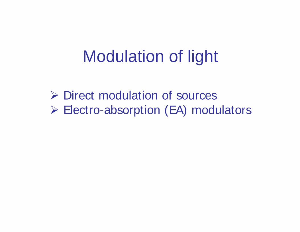
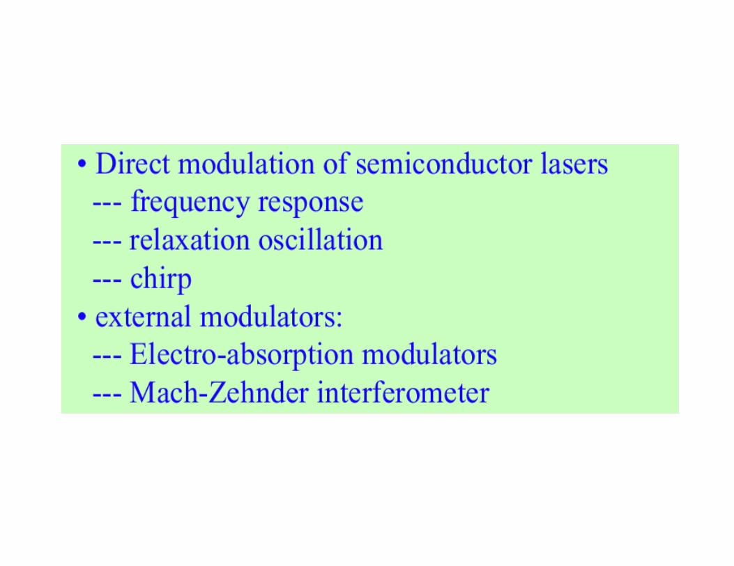
Modulation of light
Direct modulation of sources Electro-absorption (EA) modulators
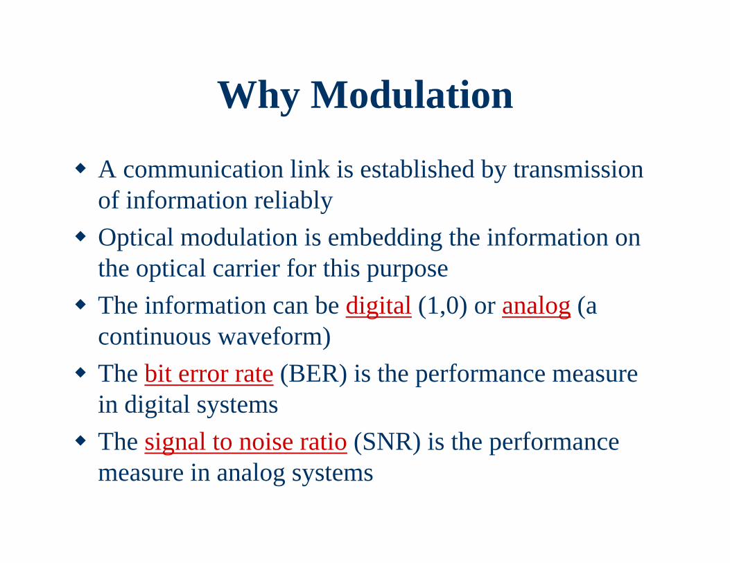
Why Modulation
A communication link is established by transmission of information reliably
Optical modulation is embedding the information on the optical carrier for this purpose
The information can be digital (1,0) or analog (a continuous waveform)
The bit error rate (BER) is the performance measure in digital systems
The signal to noise ratio (SNR) is the performance measure in analog systems

Types of Optical Modulation Direct modulation is done by superimposing the modulating
(message) signal on the driving current External modulation is done after the light is generated; the
laser is driven by a dc current and the modulation is done after that separately
Both these schemes can be done with either digital or analogmodulating signals
In external modulation, the laser emits continuous wave (CW) light and the modulation is done in the fiber
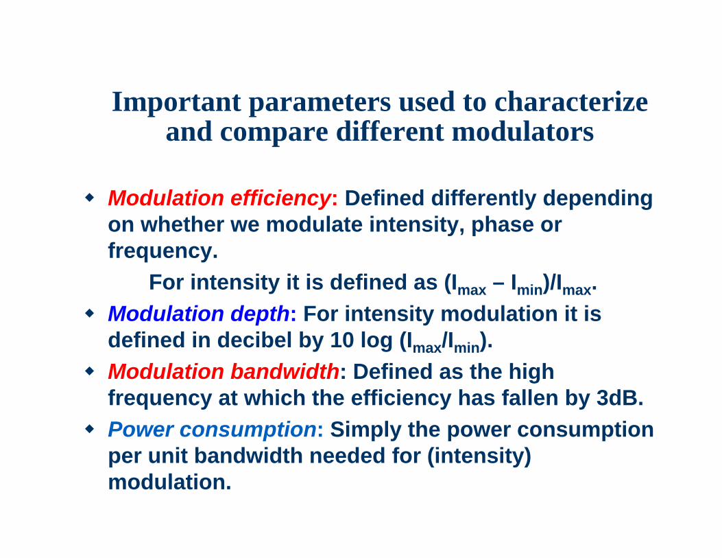
Important parameters used to characterize and compare different modulators
Modulation efficiency: Defined differently depending on whether we modulate intensity, phase or frequency.
For intensity it is defined as (Imax – Imin)/Imax. Modulation depth: For intensity modulation it is
defined in decibel by 10 log (Imax/Imin). Modulation bandwidth: Defined as the high
frequency at which the efficiency has fallen by 3dB. Power consumption: Simply the power consumption
per unit bandwidth needed for (intensity) modulation.
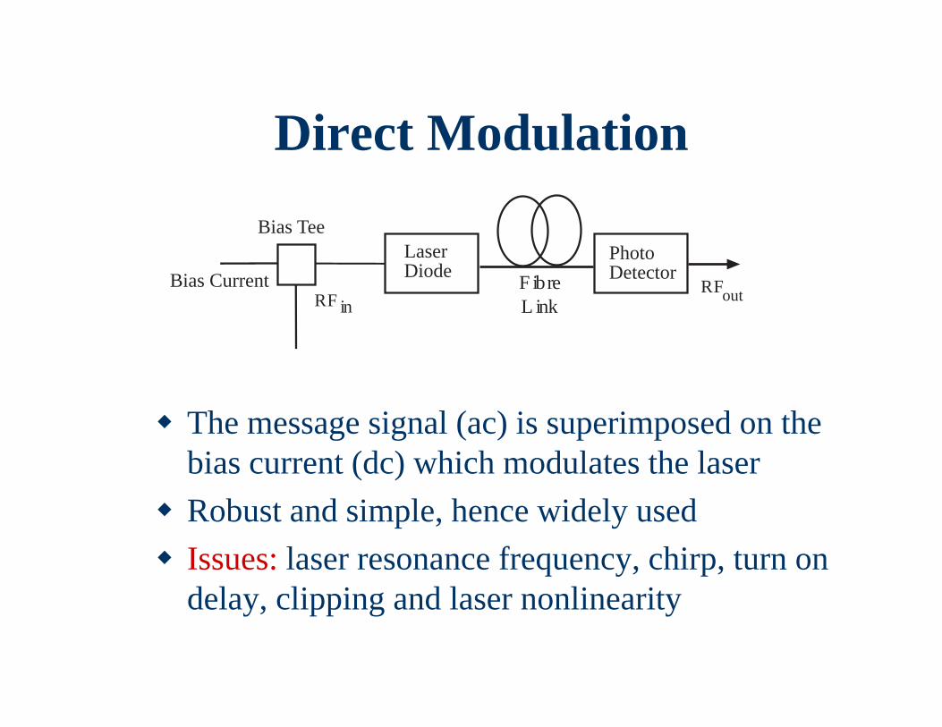
RF in
Bias Current
Bias TeeLaserDiode
PhotoDetectorF ibre
L inkRFout
Direct Modulation
The message signal (ac) is superimposed on the bias current (dc) which modulates the laser
Robust and simple, hence widely used Issues: laser resonance frequency, chirp, turn on
delay, clipping and laser nonlinearity
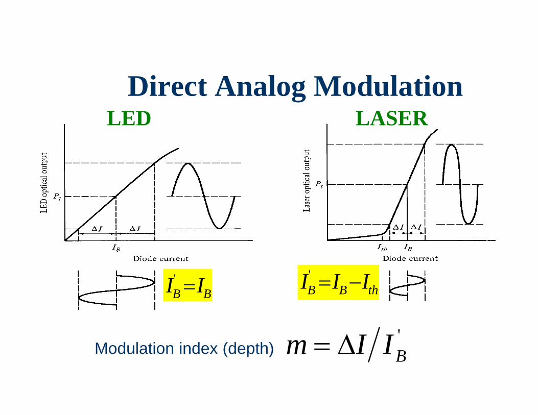
Direct Analog ModulationLED LASER
Modulation index (depth) 'BIIm
BB II 'thBB III '
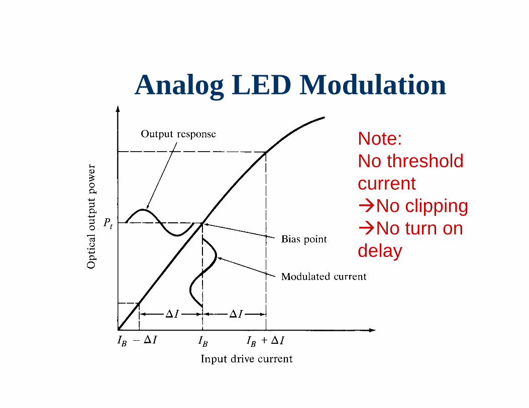
Analog LED Modulation
Note: No threshold current No clippingNo turn on delay
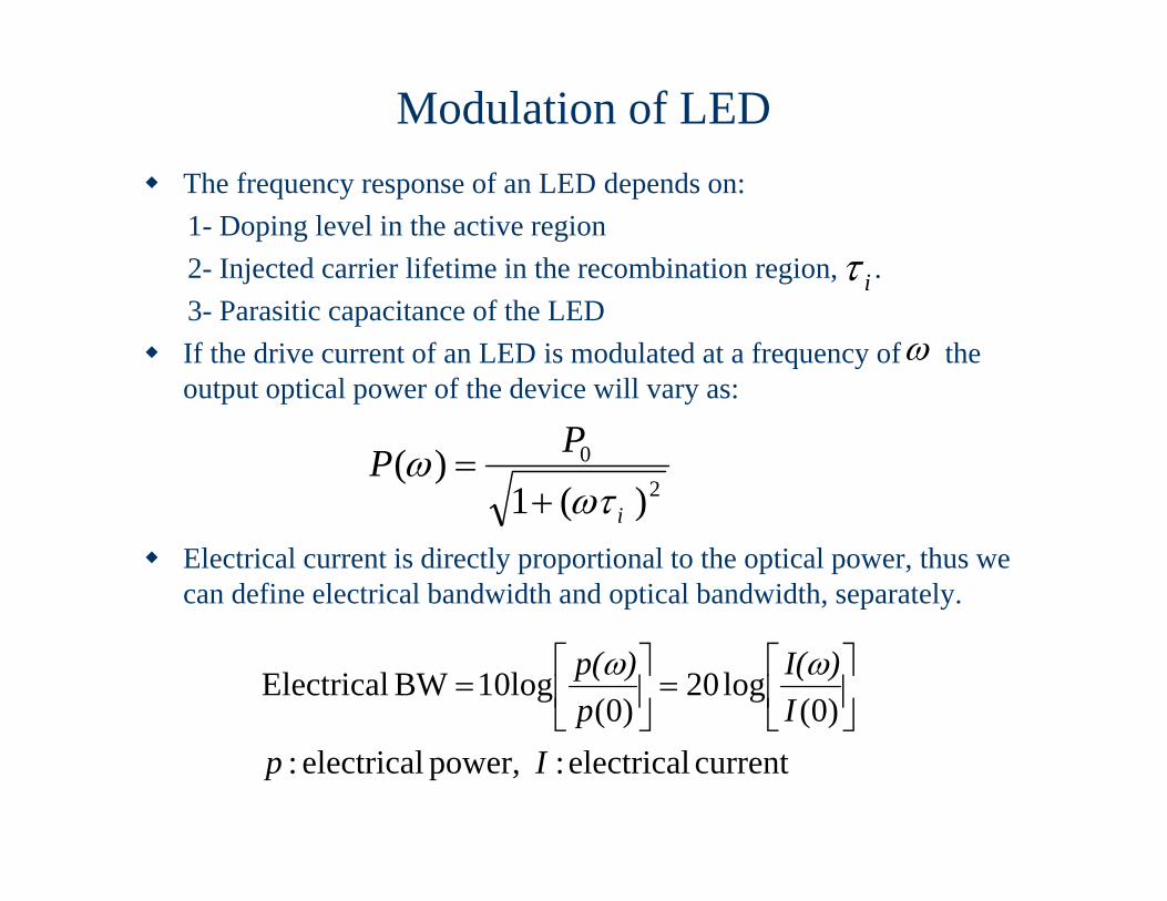
Modulation of LED The frequency response of an LED depends on:
1- Doping level in the active region2- Injected carrier lifetime in the recombination region, .3- Parasitic capacitance of the LED
If the drive current of an LED is modulated at a frequency of the output optical power of the device will vary as:
Electrical current is directly proportional to the optical power, thus we can define electrical bandwidth and optical bandwidth, separately.
20
)(1)(
i
PP
i
current electrical : power, electrical:)0(
log20)0(
10log BW Electrical
IpI
)I(p
)p(
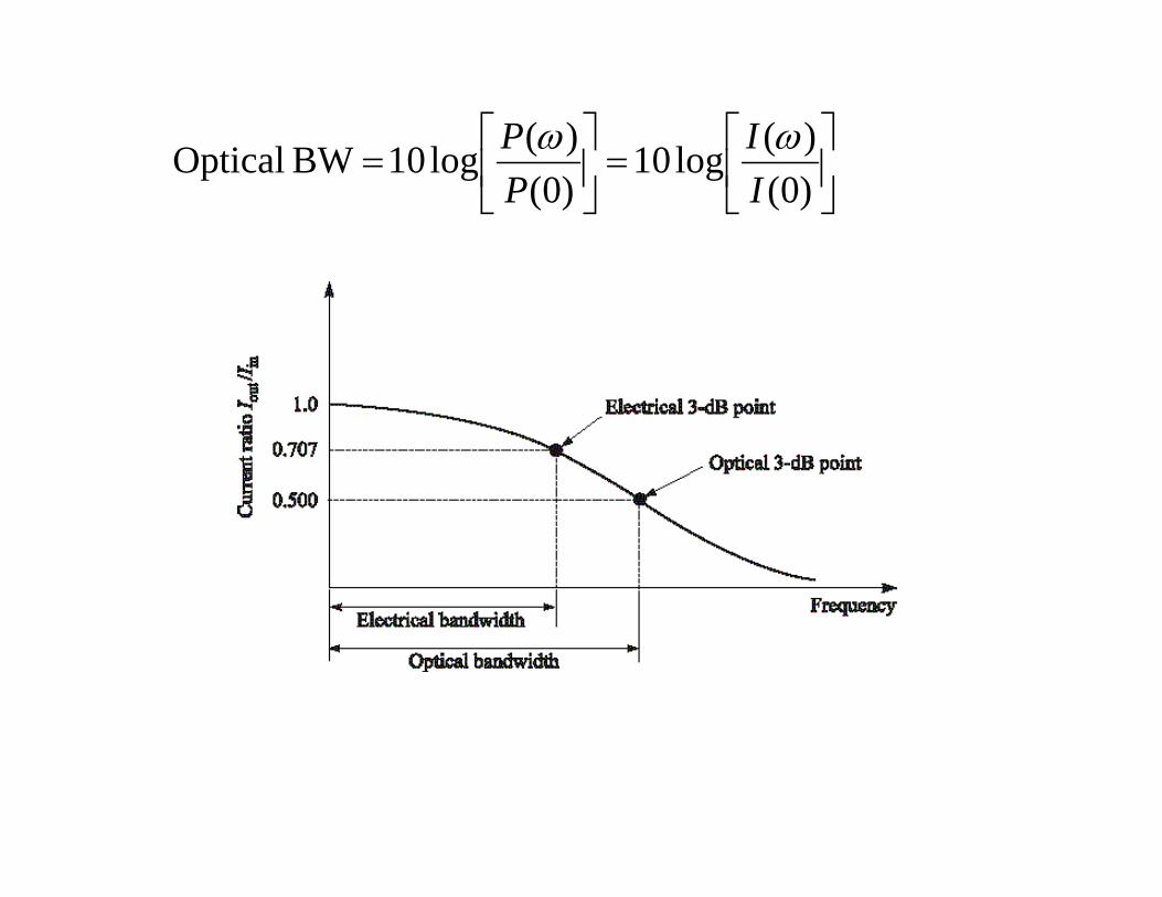
)0()(log10
)0()(log10 BW Optical
II
PP

Modulation of Laser Diodes• Internal Modulation: Simple but suffers from non-linear effects.• External Modulation: for rates greater than 2 Gb/s, more
complex, higher performance.• Most fundamental limit for the modulation rate is set by the
photon life time in the laser cavity:
• Another fundamental limit on modulation frequency is the relaxation oscillation frequency given by:
thph
gnc
RRLnc
21
1ln211
2/1
1121
thphsp IIf
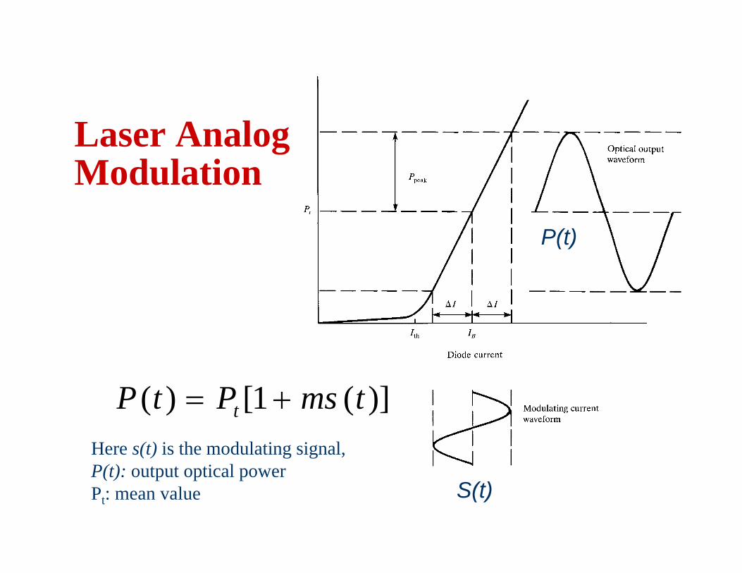
Laser Analog Modulation
)](1[)( tmsPtP t
S(t)
P(t)
Here s(t) is the modulating signal,P(t): output optical powerPt: mean value
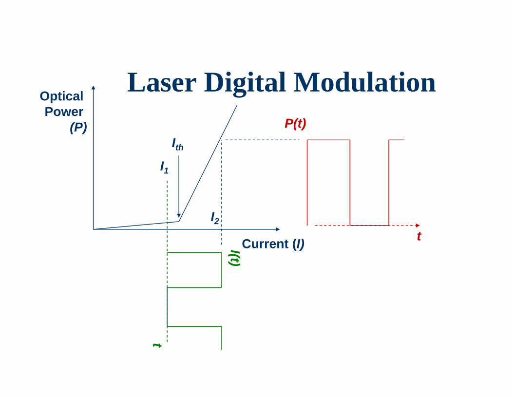
Laser Digital Modulation
Current (I)I(t)
IthI1
t
P(t)
tI2
Optical Power
(P)
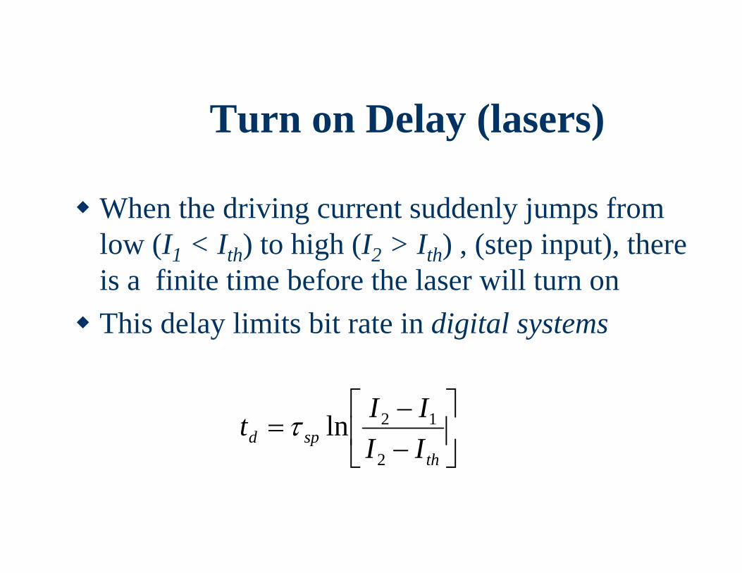
Turn on Delay (lasers)
When the driving current suddenly jumps from low (I1 < Ith) to high (I2 > Ith) , (step input), there is a finite time before the laser will turn on This delay limits bit rate in digital systems
th
spd IIIIt
2
12ln
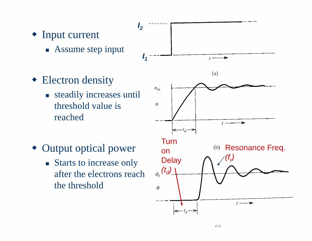
Input current Assume step input
Electron density steadily increases until
threshold value is reached
Output optical power Starts to increase only
after the electrons reach the threshold
Turn on Delay(td)
Resonance Freq.(fr)
I1
I2
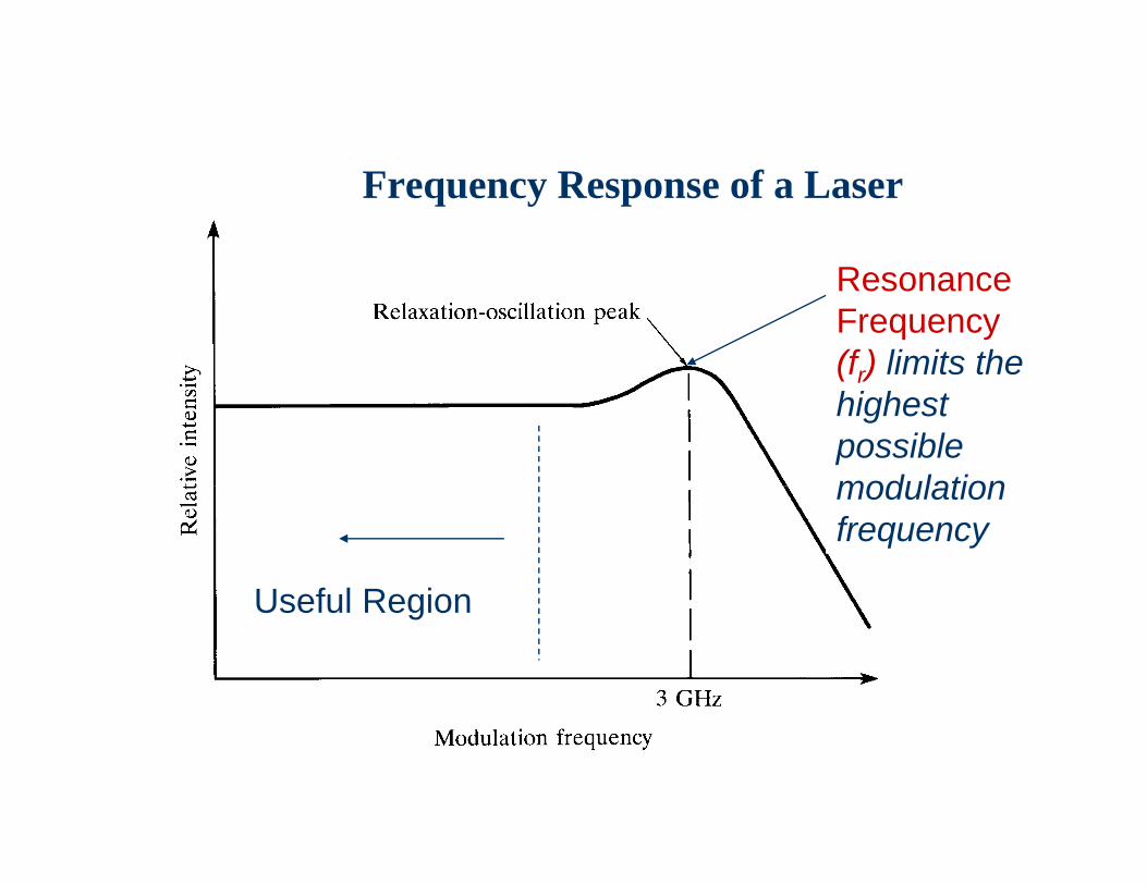
Frequency Response of a Laser
Resonance Frequency(fr) limits the highest possible modulation frequency
Useful Region
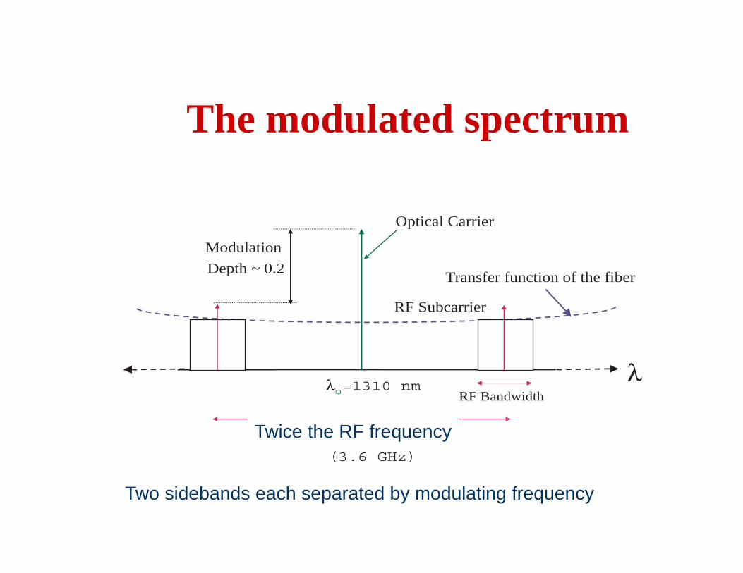
The modulated spectrum
λλo=1310 nm
0.02 nm
(3.6 GHz)
Transfer function of the fiber
Optical Carrier
RF Subcarrier
RF Bandwidth
Modulation
Depth ~ 0.2
Two sidebands each separated by modulating frequency
Twice the RF frequency
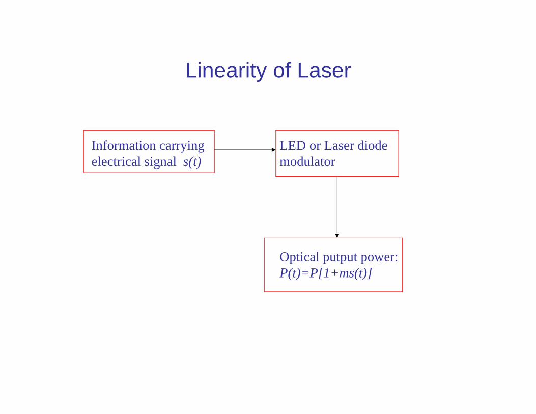
Linearity of Laser
Information carrying electrical signal s(t)
LED or Laser diodemodulator
Optical putput power:P(t)=P[1+ms(t)]
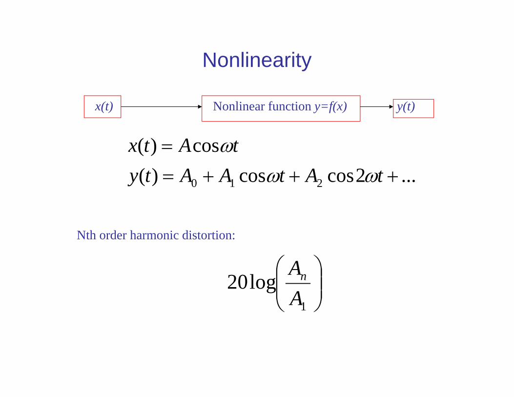
Nonlinearity
...2coscos)(cos)(
210
tAtAAtytAtx
x(t) Nonlinear function y=f(x) y(t)
Nth order harmonic distortion:
1
log20AAn
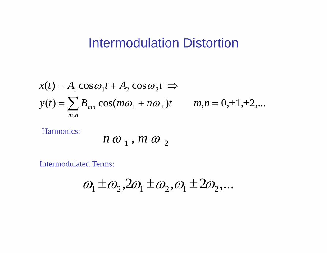
Intermodulation Distortion
nmmn m,ntnmBty
tAtAtx
,21
2211
2,...1,0, )cos()( coscos)(
Harmonics:21 , mn
Intermodulated Terms:
,...2,2, 212121
Laser Noise
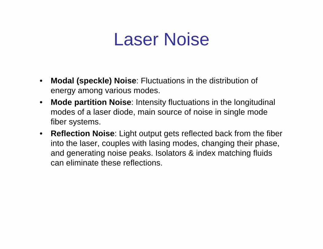
• Modal (speckle) Noise: Fluctuations in the distribution of energy among various modes.
• Mode partition Noise: Intensity fluctuations in the longitudinal modes of a laser diode, main source of noise in single mode fiber systems.
• Reflection Noise: Light output gets reflected back from the fiber into the laser, couples with lasing modes, changing their phase, and generating noise peaks. Isolators & index matching fluids can eliminate these reflections.
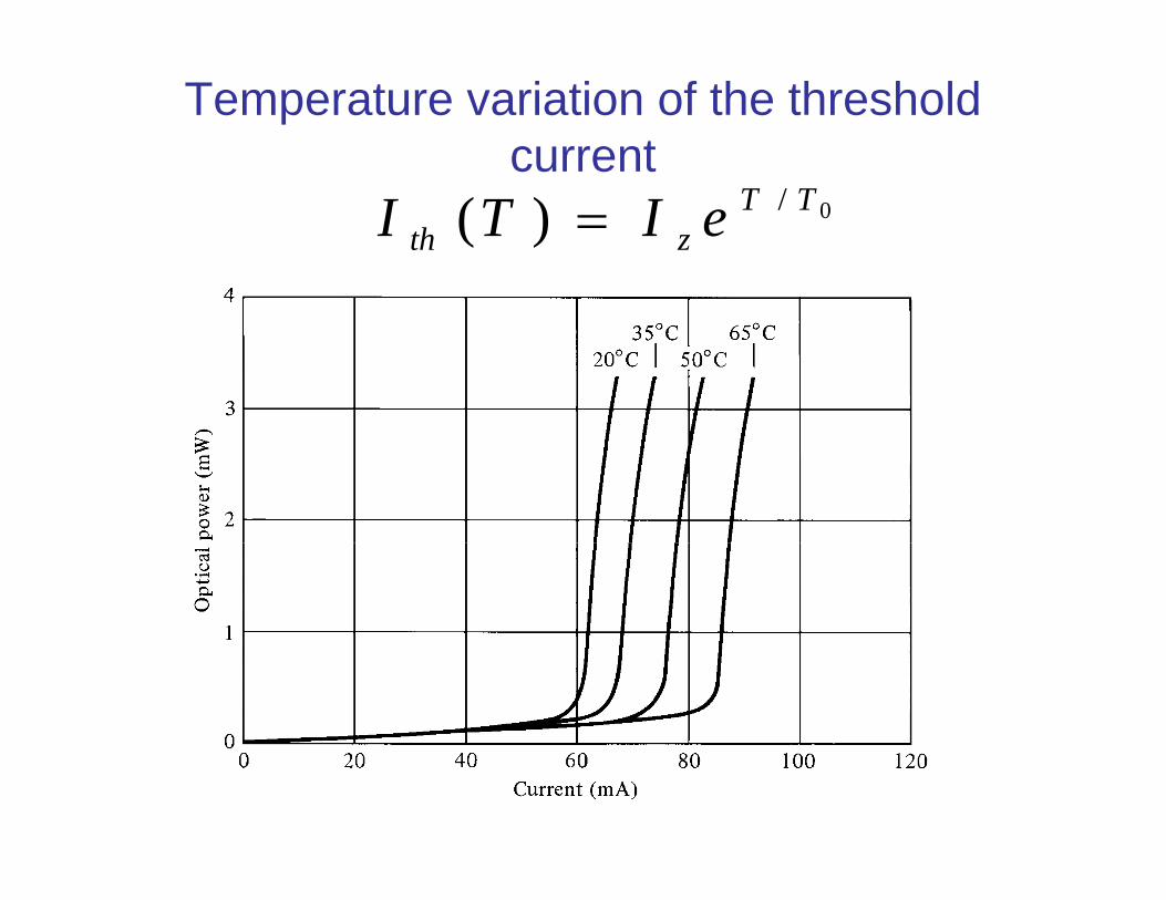
Temperature variation of the threshold current
0/)( TTzth eITI
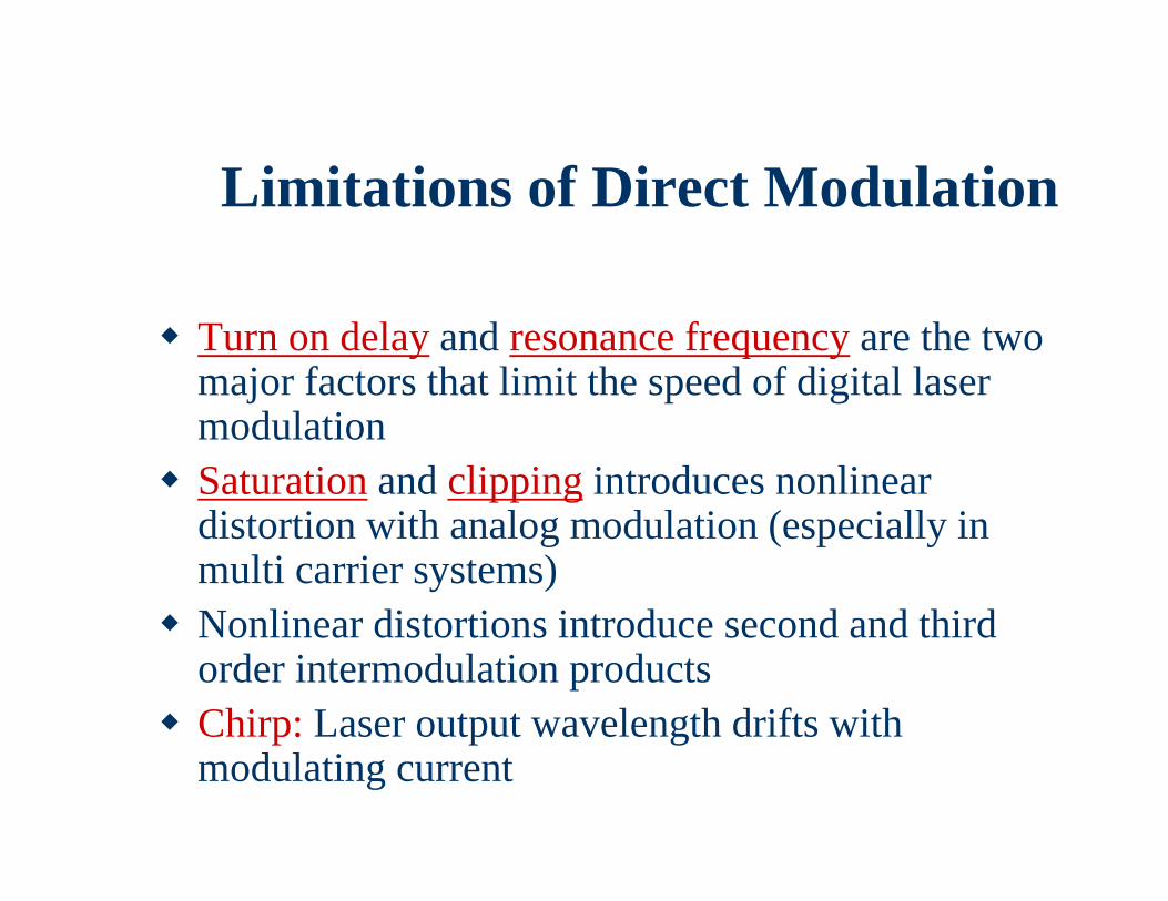
Limitations of Direct Modulation
Turn on delay and resonance frequency are the two major factors that limit the speed of digital laser modulation
Saturation and clipping introduces nonlinear distortion with analog modulation (especially in multi carrier systems)
Nonlinear distortions introduce second and third order intermodulation products
Chirp: Laser output wavelength drifts with modulating current
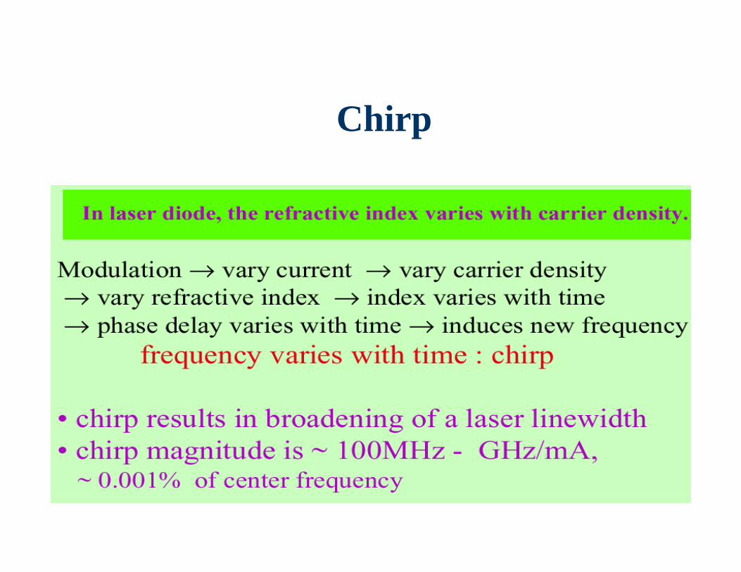
Chirp
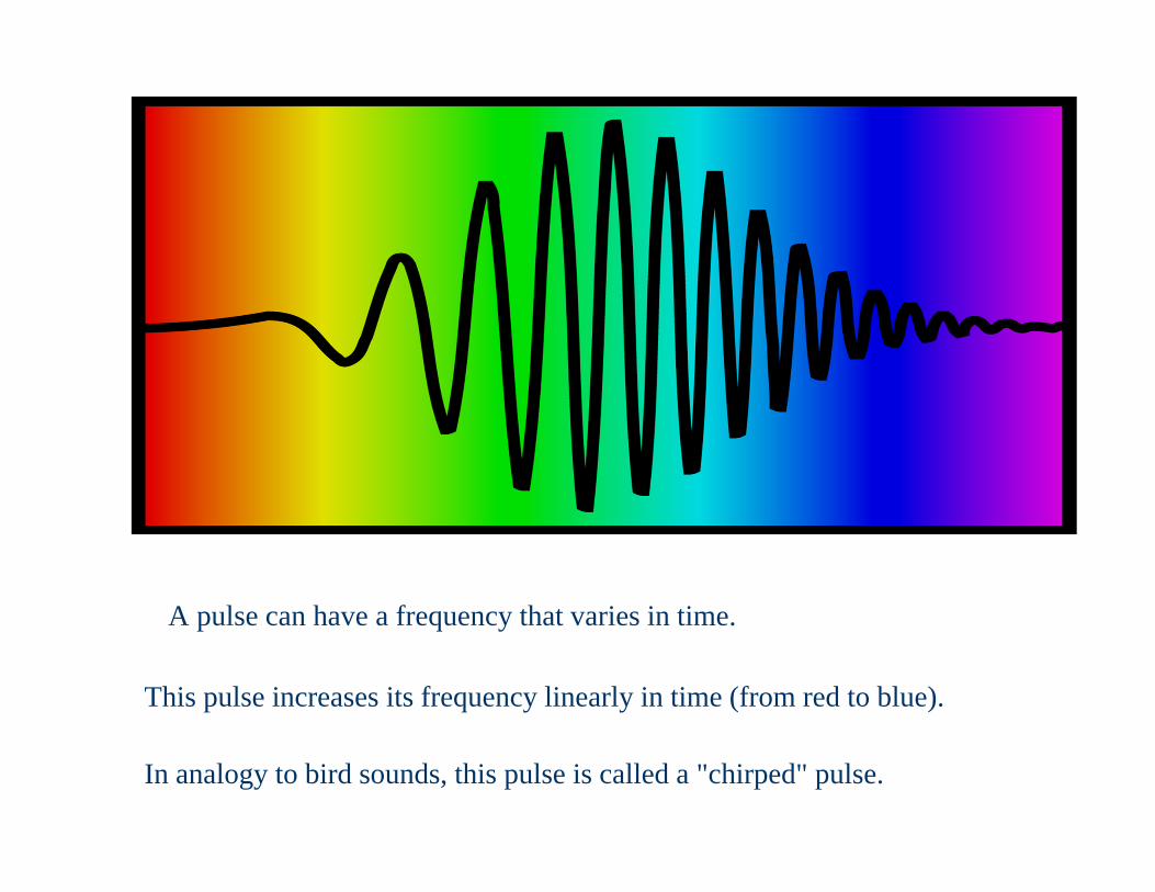
The Chirped Pulse
A pulse can have a frequency that varies in time.
This pulse increases its frequency linearly in time (from red to blue).
In analogy to bird sounds, this pulse is called a "chirped" pulse.
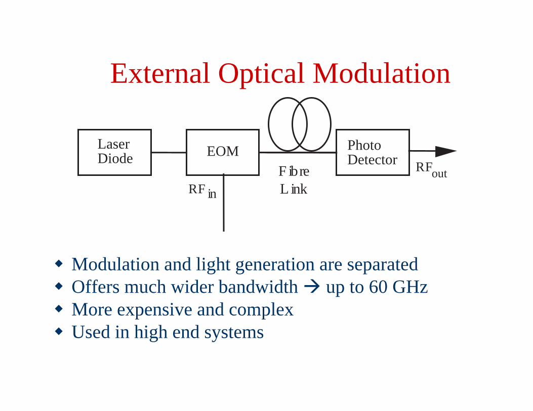
External Optical Modulation
Modulation and light generation are separated Offers much wider bandwidth up to 60 GHz More expensive and complex Used in high end systems
EOM
RF in
PhotoDetector
LaserDiode
F ibreL ink
RFout
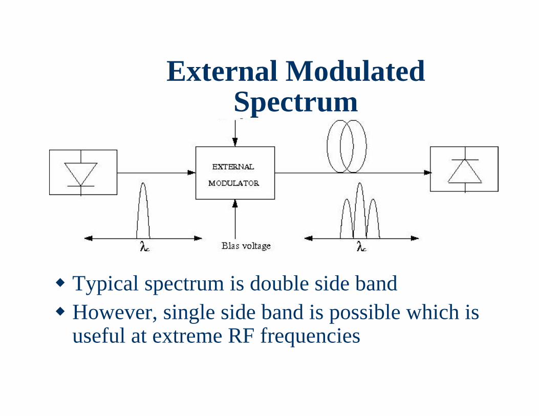
External Modulated Spectrum
Typical spectrum is double side band However, single side band is possible which is
useful at extreme RF frequencies
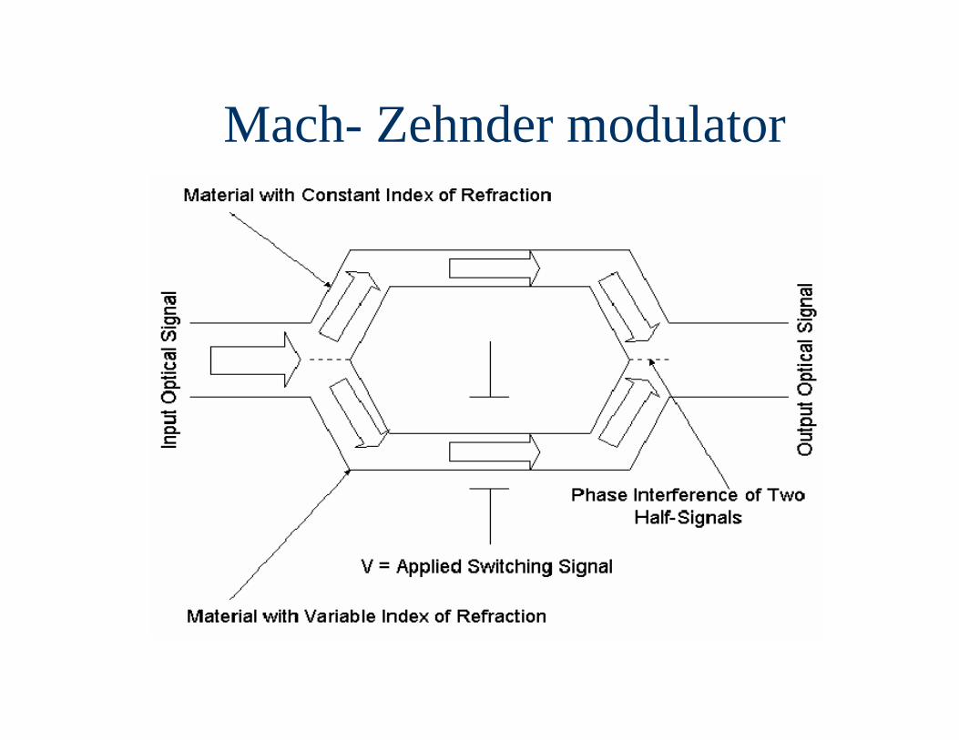
Mach- Zehnder modulator
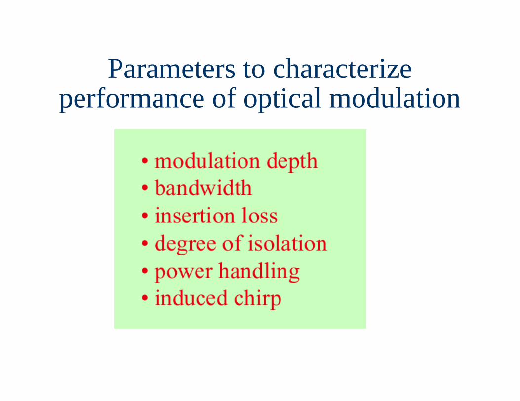
Parameters to characterize performance of optical modulation
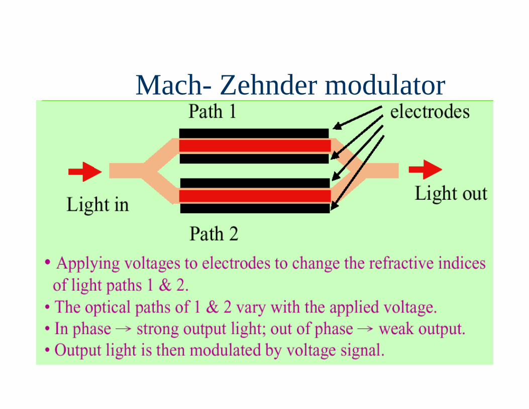
Mach- Zehnder modulator
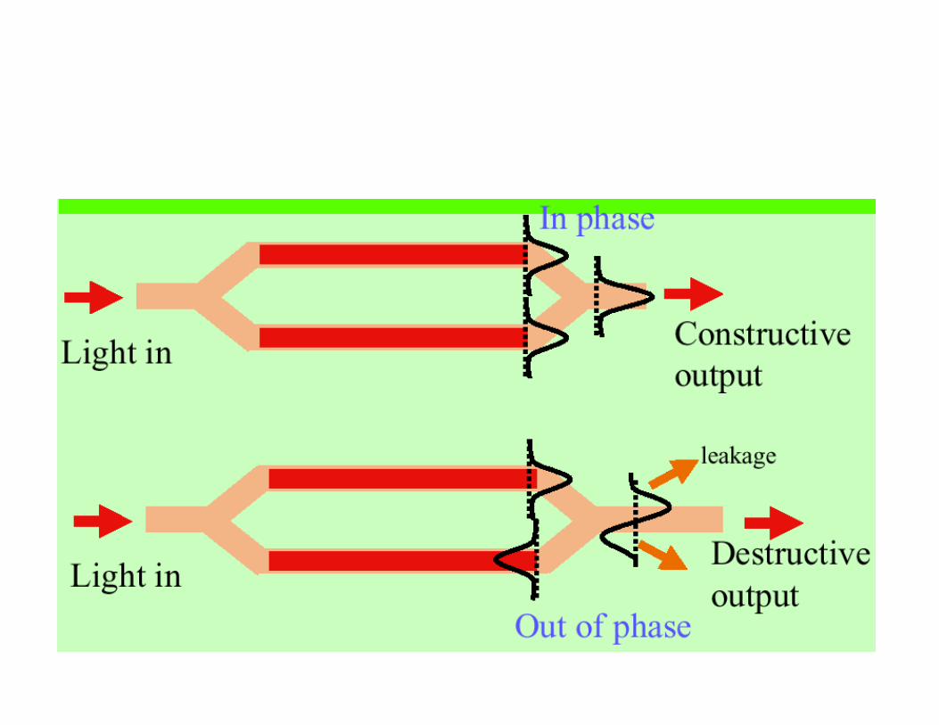
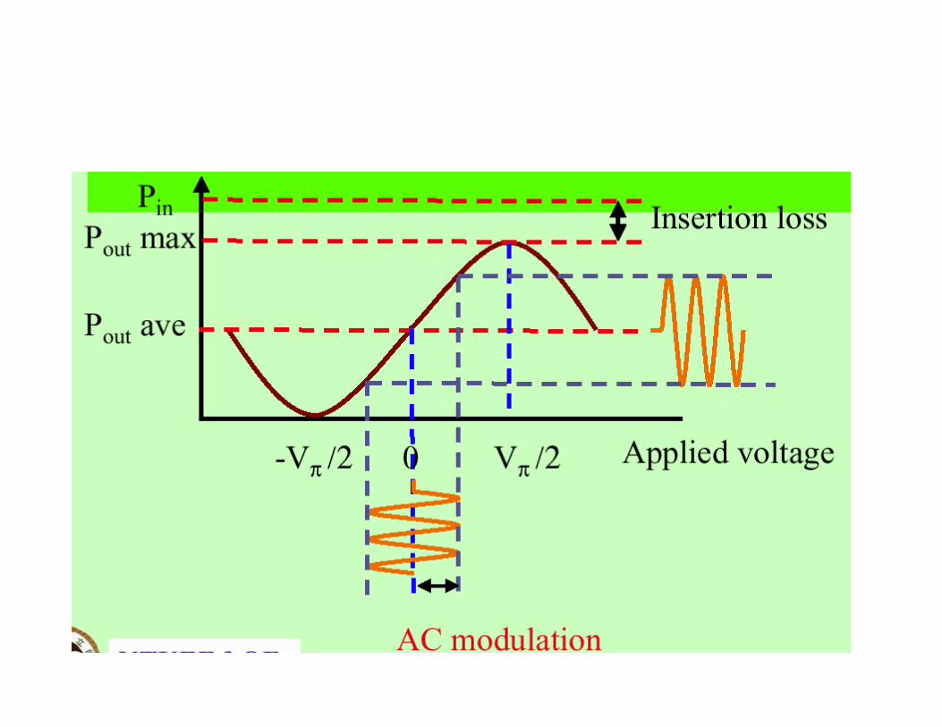
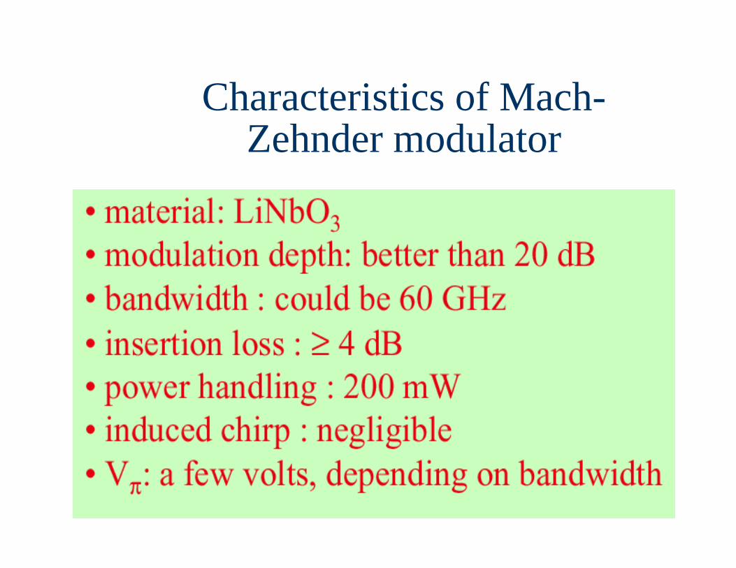
Characteristics of Mach-Zehnder modulator

Electroabsorption (EA) Modulator
EA modulator is a semiconductor device with the same structure as the laser diode.
In laser diodes, we inject large enough current to achieve stimulated emission. While in EA modulator, we apply electric field (reverse bias) to change the absorption spectrum. No carriers are injected into the active region. However, carriers are generated due to absorption of light.
Chuang Ch. 14
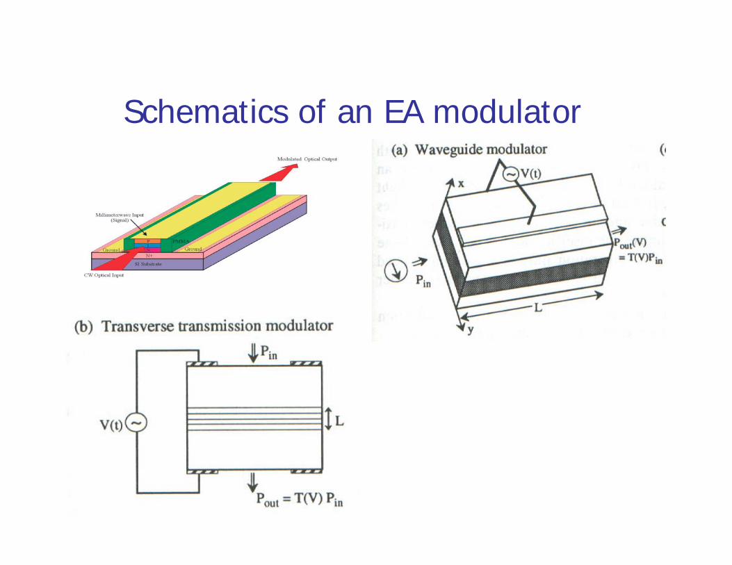
Schematics of an EA modulator
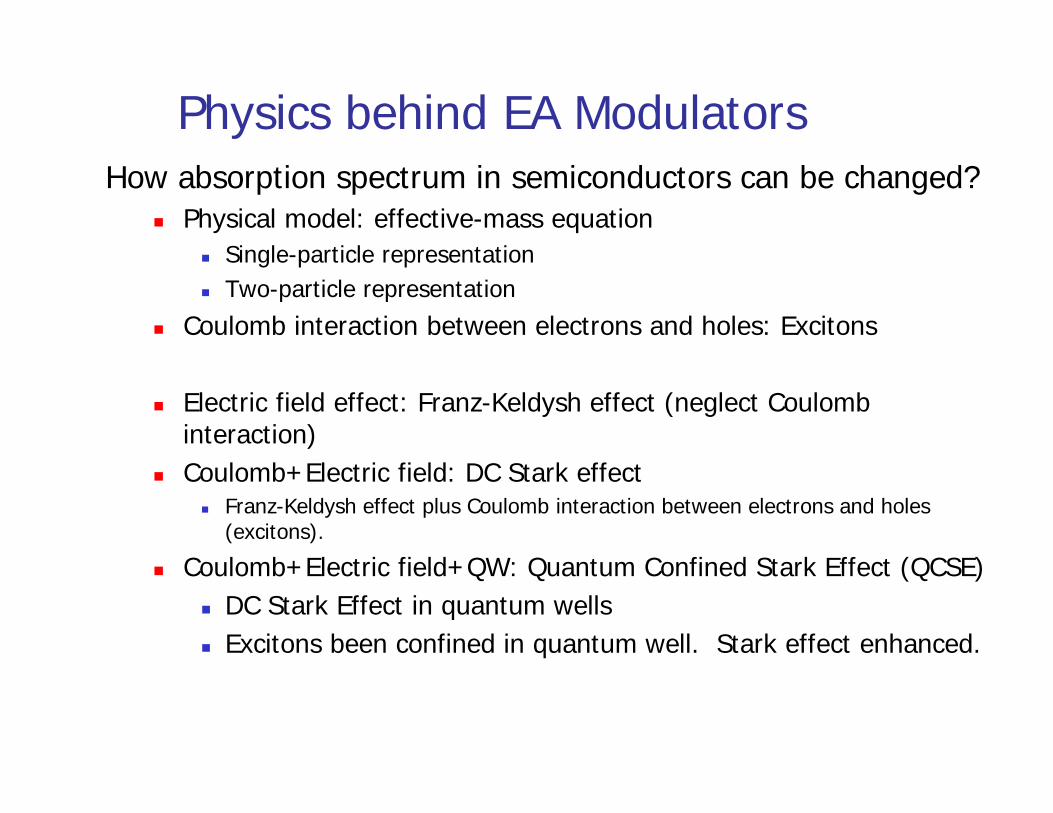
Physics behind EA ModulatorsHow absorption spectrum in semiconductors can be changed?
Physical model: effective-mass equation Single-particle representation Two-particle representation
Coulomb interaction between electrons and holes: Excitons
Electric field effect: Franz-Keldysh effect (neglect Coulomb interaction)
Coulomb+Electric field: DC Stark effect Franz-Keldysh effect plus Coulomb interaction between electrons and holes
(excitons).
Coulomb+Electric field+QW: Quantum Confined Stark Effect (QCSE) DC Stark Effect in quantum wells Excitons been confined in quantum well. Stark effect enhanced.
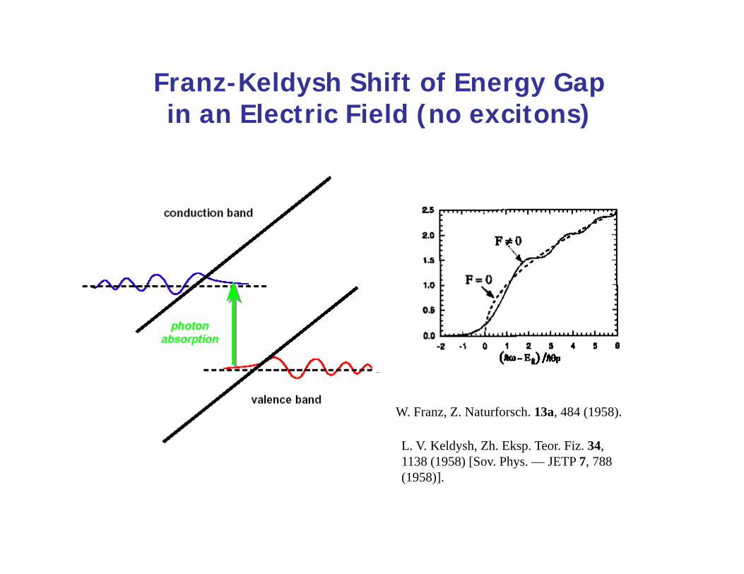
Franz-Keldysh Shift of Energy Gap in an Electric Field (no excitons)
W. Franz, Z. Naturforsch. 13a, 484 (1958).
L. V. Keldysh, Zh. Eksp. Teor. Fiz. 34, 1138 (1958) [Sov. Phys. — JETP 7, 788 (1958)].
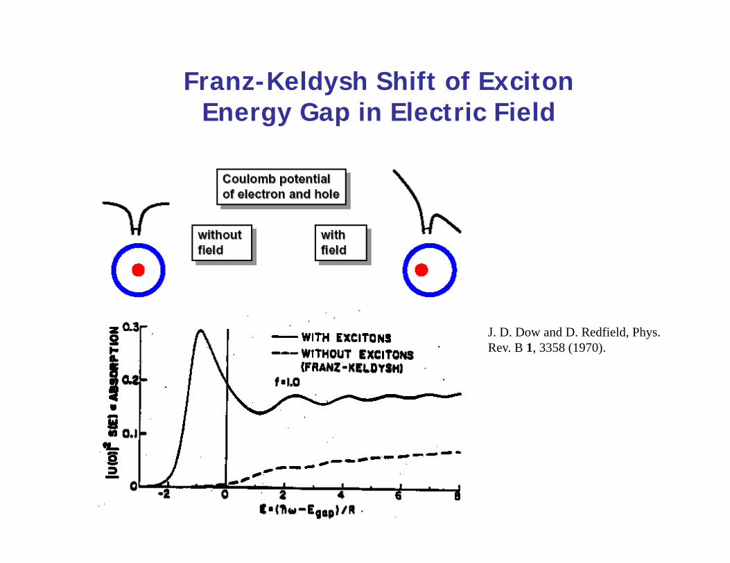
Franz-Keldysh Shift of Exciton Energy Gap in Electric Field
J. D. Dow and D. Redfield, Phys. Rev. B 1, 3358 (1970).
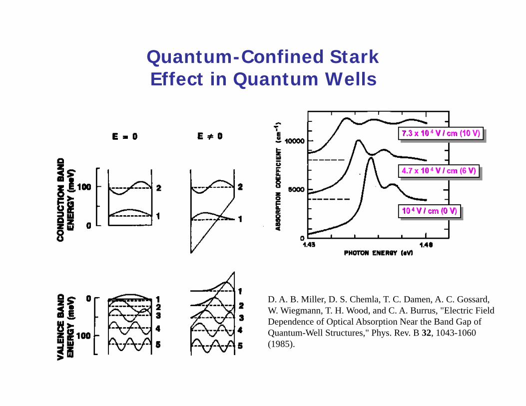
Quantum-Confined Stark Effect in Quantum Wells
D. A. B. Miller, D. S. Chemla, T. C. Damen, A. C. Gossard, W. Wiegmann, T. H. Wood, and C. A. Burrus, "Electric Field Dependence of Optical Absorption Near the Band Gap of Quantum-Well Structures," Phys. Rev. B 32, 1043-1060 (1985).
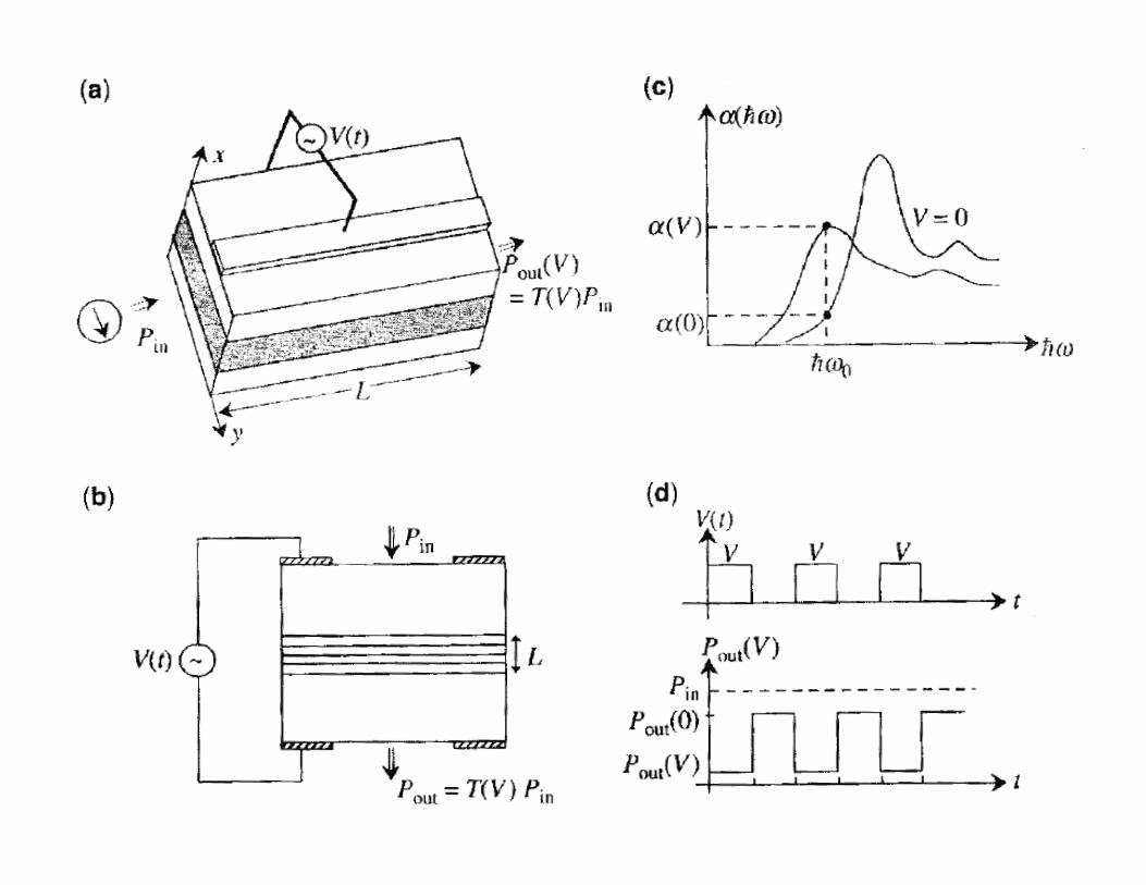
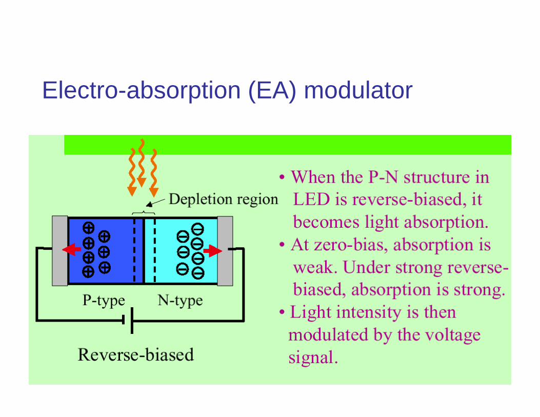
Electro-absorption (EA) modulator
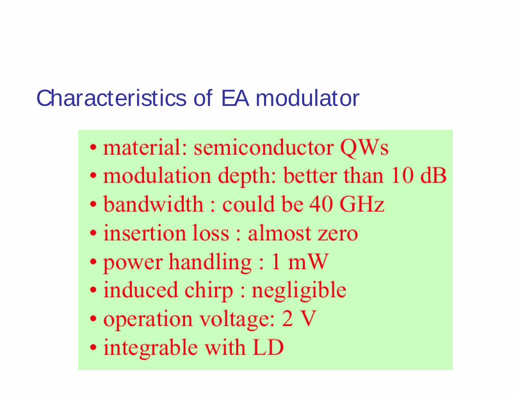
Characteristics of EA modulator

Advantages of EA modulators
Zero biasing voltage Low driving voltage Low/negative chirp high bandwidth Integrated with DFB
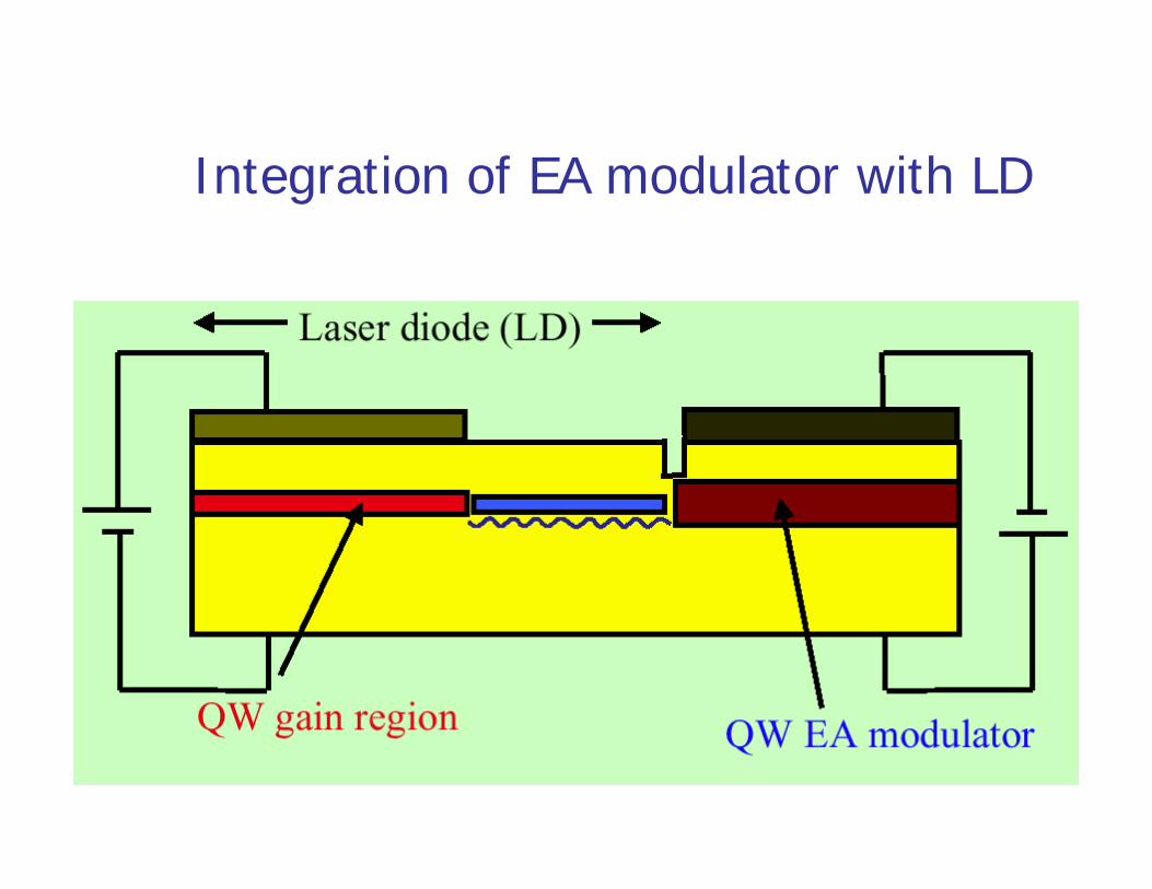
Integration of EA modulator with LD
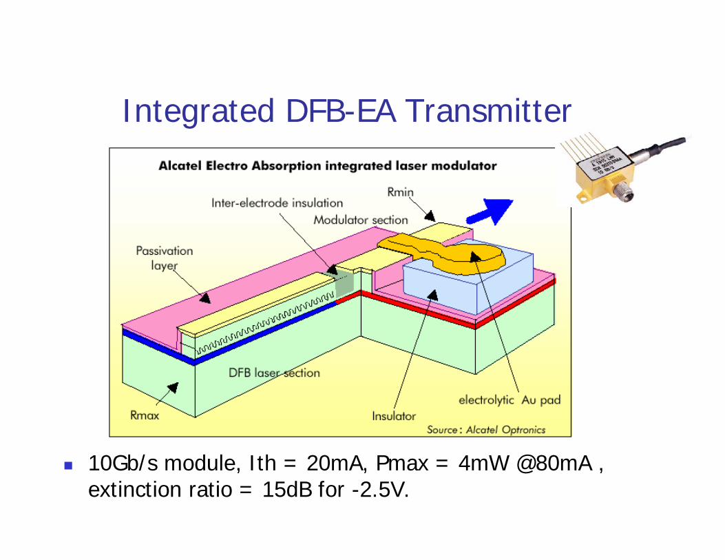
Integrated DFB-EA Transmitter
10Gb/s module, Ith = 20mA, Pmax = 4mW @80mA , extinction ratio = 15dB for -2.5V.
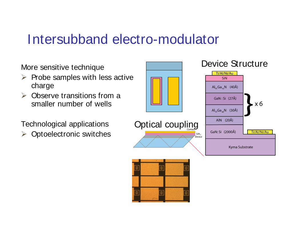
Intersubband electro-modulator
Device Structure
Optical coupling
More sensitive technique Probe samples with less active
charge Observe transitions from a
smaller number of wells
Technological applications Optoelectronic switches
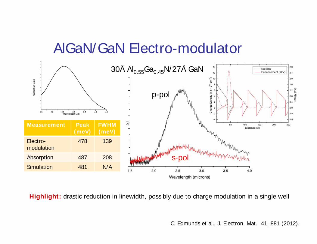
AlGaN/GaN Electro-modulator30Å Al0.55Ga0.45N/27Å GaN
Measurement Peak (meV)
FWHM (meV)
Electro-modulation
478 139
Absorption 487 208
Simulation 481 N/A
Highlight: drastic reduction in linewidth, possibly due to charge modulation in a single well
C. Edmunds et al., J. Electron. Mat. 41, 881 (2012).
p-pol
s-pol
Summary of Optical Modulation
Direct modulation on semiconductor lasers: Output frequency drifts
carrier induced (chirp) temperature variation due to carrier modulation
Limited modulation depth (don’t want to turn off laser)
External modulation Electro-optical modulation (low efficiency) Electroabsorption (EA) modulation (smaller modulation
bandwidth)