Embed Size (px)
Citation preview
Phone (309) 566-3000 • Fax (309) 566-3079 • www.rohnnet.com • The Industry Standard
P D I R E C T E M B E D P O L E S
D I R E C T E M B E D P O L ES T A N D A R D D E S I G N S
220© 2011 ROHN PRODUCTS LLC
180º
270º90º
Safety Climb Support Bracket(Safety Cable System Ordered Separately)
0º
C
D
A B
PORT ORIENTATIONS
8’ Separation
Splice
4’ 3”
AggregateBackfill
2’
Embedment
Bearing Plate(Allows Drainage)
Port A
Port B
Port C
Port D
Cap Plate
(3) Jacking Lugs
Pole HeightAbove Grade
6” Gravel Base
1’ 3”
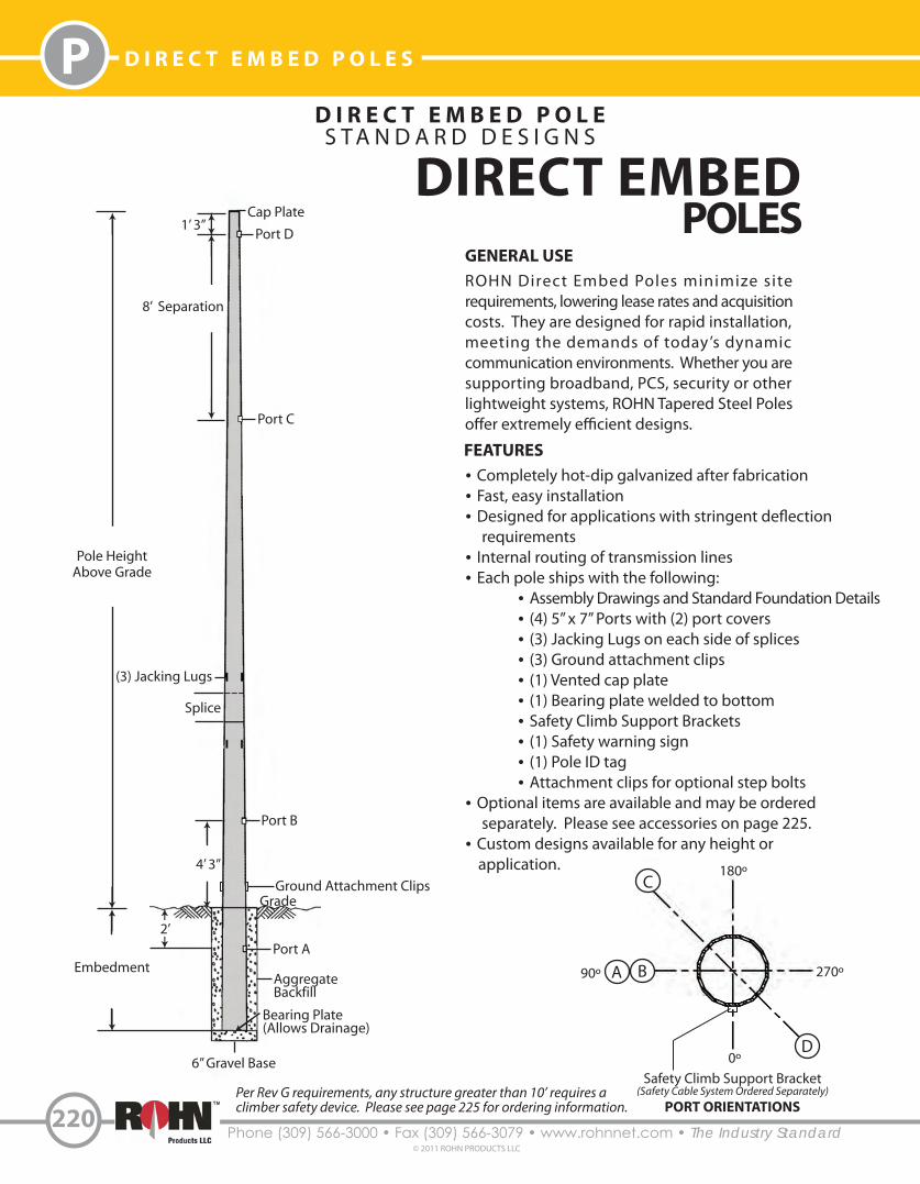
GENERAL USEROHN Direct Embed Poles minimize site requirements, lowering lease rates and acquisition costs. They are designed for rapid installation, meeting the demands of today’s dynamic communication environments. Whether you aresupporting broadband, PCS, security or other lightweight systems, ROHN Tapered Steel Poles o�er extremely e�cient designs.
FEATURES• Completely hot-dip galvanized after fabrication• Fast, easy installation• Designed for applications with stringent de�ection requirements• Internal routing of transmission lines• Each pole ships with the following: • Assembly Drawings and Standard Foundation Details • (4) 5” x 7” Ports with (2) port covers • (3) Jacking Lugs on each side of splices • (3) Ground attachment clips • (1) Vented cap plate • (1) Bearing plate welded to bottom • Safety Climb Support Brackets • (1) Safety warning sign • (1) Pole ID tag • Attachment clips for optional step bolts• Optional items are available and may be ordered separately. Please see accessories on page 225.• Custom designs available for any height or application.
DIRECT EMBEDPOLES
Grade
Per Rev G requirements, any structure greater than 10’ requires a climber safety device. Please see page 225 for ordering information.
Ground Attachment Clips
221Phone (309) 566-3000 • Fax (309) 566-3079 • www.rohnnet.com • The Industry Standard© 2011 ROHN PRODUCTS LLC
PD I R E C T E M B E D P O L E S
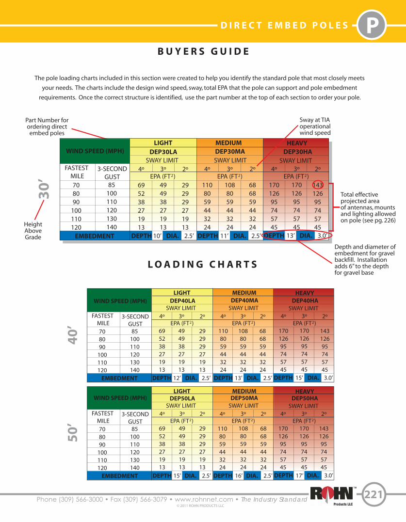
Part Number forordering directembed poles
Sway at TIAoperationalwind speed
Total effective projected area of antennas, mountsand lighting allowed on pole (see pg. 226)
LIGHT MEDIUM HEAVY
SWAY LIMIT SWAY LIMIT SWAY LIMIT
WIND SPEED (MPH)
FASTEST MILE
3-SECONDGUST
708090
100110120
85100110120130140
4º
695238271913
3º
494938271913
2º
292929271913
4º
1108059443224
3º
1088059443224
2º
686859443224
4º
17012695745745
3º
17012695745745
2º
14312695745745
30
’
EMBEDMENT DEPTH DIA.10’ 2.5’ DEPTH DIA.11’ 2.5’ DEPTH DIA.13’ 3.0’
EPA (FT )2 EPA (FT )2 EPA (FT )2
DEP30HADEP30MADEP30LA
Depth and diameter of embedment for gravelbackfill. Installationadds 6” to the depthfor gravel base
B U Y E R S G U I D E
L O A D I N G C H A R T S
LIGHT MEDIUM HEAVY
SWAY LIMIT SWAY LIMIT SWAY LIMITWIND SPEED (MPH)
FASTEST MILE
3-SECONDGUST
708090
100110120
85100110120130140
4º
695238271913
3º
494938271913
2º
292929271913
4º
1108059443224
3º
1088059443224
2º
686859443224
4º
17012695745745
3º
17012695745745
2º
14312695745745
40
’
EMBEDMENT DEPTH DIA.12’ 2.5’ DEPTH DIA.13’ 2.5’ DEPTH DIA.15’ 3.0’
EPA (FT )2 EPA (FT )2 EPA (FT )2
DEP40HADEP40MADEP40LA
LIGHT MEDIUM HEAVY
SWAY LIMIT SWAY LIMIT SWAY LIMITWIND SPEED (MPH)
FASTEST MILE
3-SECONDGUST
708090
100110120
85100110120130140
4º
695238271913
3º
494938271913
2º
292929271913
4º
1108059443224
3º
1088059443224
2º
686859443224
4º
17012695745745
3º
17012695745745
2º
14312695745745
50
’
EMBEDMENT DEPTH DIA.15’ 2.5’ DEPTH DIA.16’ 2.5’ DEPTH DIA.17’ 3.0’
EPA (FT )2 EPA (FT )2 EPA (FT )2
DEP50HADEP50MADEP50LA
The pole loading charts included in this section were created to help you identify the standard pole that most closely meets
your needs. The charts include the design wind speed, sway, total EPA that the pole can support and pole embedment
requirements. Once the correct structure is identified, use the part number at the top of each section to order your pole.
HeightAboveGrade
Phone (309) 566-3000 • Fax (309) 566-3079 • www.rohnnet.com • The Industry Standard
P D I R E C T E M B E D P O L E S
222© 2011 ROHN PRODUCTS LLC
L O A D I N G C H A R T S
LIGHT MEDIUM HEAVY
SWAY LIMIT SWAY LIMIT SWAY LIMITWIND SPEED (MPH)
FASTEST MILE
3-SECONDGUST
708090
100110120
85100110120130140
4º
28281992-
3º
17171792-
2º
66662-
4º
6550321992
3º
4444321992
2º
2323231992
4º
1178258412818
3º
938258412818
2º
565656412818
LIGHT MEDIUM HEAVY
SWAY LIMIT SWAY LIMIT SWAY LIMITWIND SPEED (MPH)
FASTEST MILE
3-SECONDGUST
708090
100110120
85100110120130140
4º
2121144--
3º
1111114--
2º
22222-
4º
514325123-
3º
333325123-
2º
161616123-
4º
1067350332113
3º
777350332113
2º
444444332113
80
’9
0’
EMBEDMENT DEPTH DIA.16’ 3.0’ DEPTH DIA.18’ 3.0’ DEPTH DIA.20’ 3.5’
EMBEDMENT DEPTH DIA.18’ 3.0’ DEPTH DIA.20’ 3.0’ DEPTH DIA.22’ 3.5’
LIGHT MEDIUM HEAVY
SWAY LIMIT SWAY LIMIT SWAY LIMITWIND SPEED (MPH)
FASTEST MILE
3-SECONDGUST
708090
100110120
85100110120130140
4º
4242281793
3º
2828281793
2º
1313131393
4º
896343291910
3º
636343291910
2º
363636291910
4º
1379872533928
3º
1299873533928
2º
818173533928
70
’
EMBEDMENT DEPTH DIA.16’ 3.0’ DEPTH DIA.18’ 3.0’ DEPTH DIA.20’ 3.5’
EPA (FT )2 EPA (FT )2 EPA (FT )2
DEP70HADEP70MADEP70LA
EPA (FT )2 EPA (FT )2 EPA (FT )2
DEP80HADEP80MADEP80LA
EPA (FT )2 EPA (FT )2 EPA (FT )2
DEP90HADEP90MADEP90LA
LIGHT MEDIUM HEAVY
SWAY LIMIT SWAY LIMIT SWAY LIMITWIND SPEED (MPH)
FASTEST MILE
3-SECONDGUST
708090
100110120
85100110120130140
4º
52463221148
3º
35353221148
2º
19191919148
4º
997150362517
3º
807150362517
2º
484848362517
4º
15010981614635
3º
15010981614635
2º
10410481614635
60
’
EMBEDMENT DEPTH DIA.15’ 2.5’ DEPTH DIA.17’ 3.0’ DEPTH DIA.19’ 3.0’
EPA (FT )2 EPA (FT )2 EPA (FT )2
DEP60HADEP60MADEP60LA
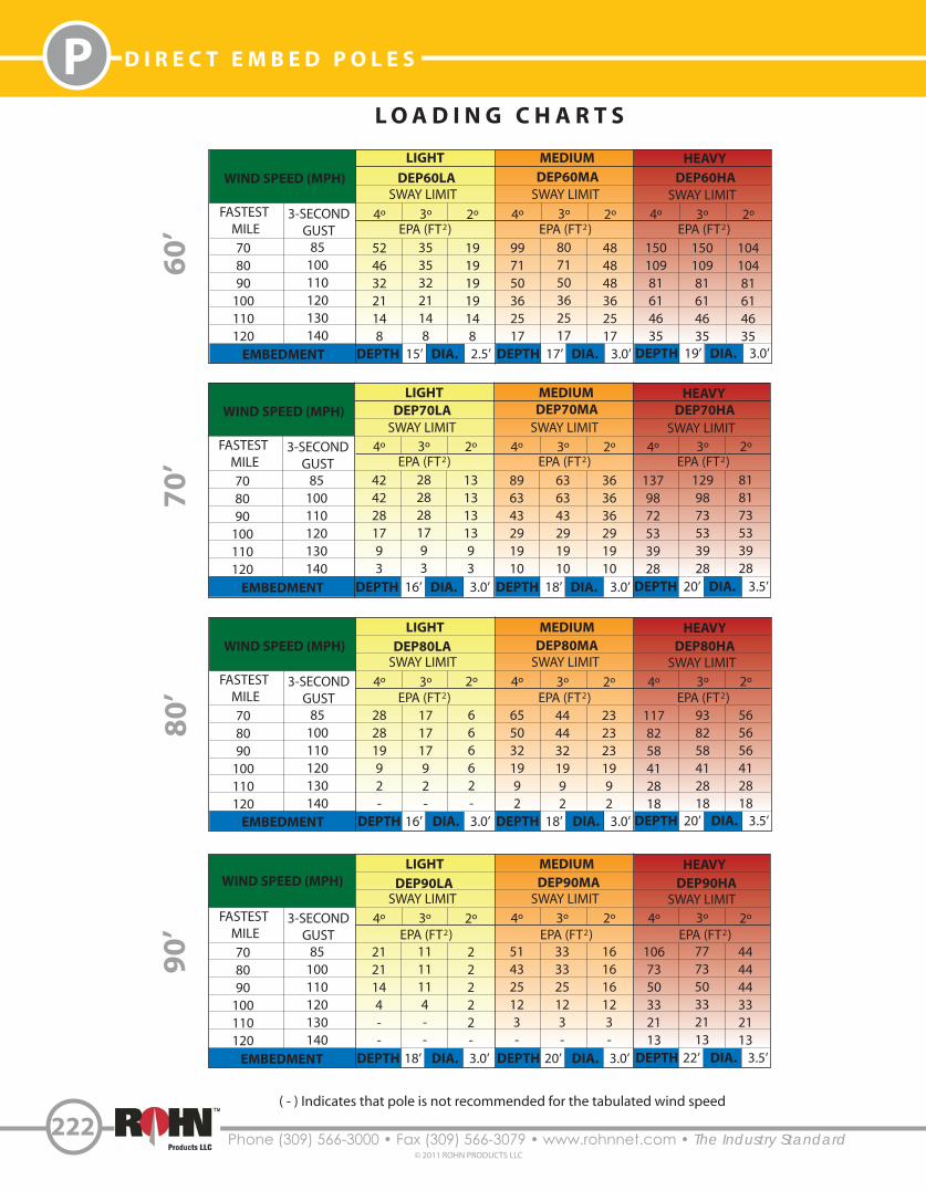
( - ) Indicates that pole is not recommended for the tabulated wind speed
223Phone (309) 566-3000 • Fax (309) 566-3079 • www.rohnnet.com • The Industry Standard© 2011 ROHN PRODUCTS LLC
PD I R E C T E M B E D P O L E S
L O A D I N G C H A R T S
LIGHT MEDIUM HEAVY
SWAY LIMIT SWAY LIMIT SWAY LIMITWIND SPEED (MPH)
FASTEST MILE
3-SECONDGUST
708090
100110120
85100110120130140
4º
1919142--
3º
8882--
2º
------
4º
39392411--
3º
24242411--
2º
6666--
4º
837651322110
3º
575751322110
2º
303030302110
13
0’
EMBEDMENT DEPTH DIA.22’ 4.0’ DEPTH DIA.23’ 4.0’ DEPTH DIA.24’ 4.5’
LIGHT MEDIUM HEAVY
SWAY LIMIT SWAY LIMIT SWAY LIMITWIND SPEED (MPH)
FASTEST MILE
3-SECONDGUST
708090
100110120
85100110120130140
4º
18185---
3º
10105---
2º
------
4º
393615---
3º
242415---
2º
666---
4º
908055362314
3º
626255362314
2º
353535352314
12
0’
EMBEDMENT DEPTH DIA.19’ 3.5’ DEPTH DIA.22’ 4.0’ DEPTH DIA.23’ 4.0’
EPA (FT )2 EPA (FT )2 EPA (FT )2
DEP120HADEP120MADEP120LA
EPA (FT )2 EPA (FT )2 EPA (FT )2
DEP130HADEP130MADEP130LA
LIGHT MEDIUM HEAVY
SWAY LIMIT SWAY LIMIT SWAY LIMITWIND SPEED (MPH)
FASTEST MILE
3-SECONDGUST
708090
100110120
85100110120130140
4º
232313---
3º
131313---
2º
------
4º
5147259--
3º
3232259--
2º
1414149--
4º
103775031178
3º
70705031178
2º
41414131178
11
0’
EMBEDMENT DEPTH DIA.19’ 3.5’ DEPTH DIA.21’ 4.0’ DEPTH DIA.22’ 4.0’
EPA (FT )2 EPA (FT )2 EPA (FT )2
DEP110HADEP110MADEP110LA
LIGHT MEDIUM HEAVY
SWAY LIMIT SWAY LIMIT SWAY LIMITWIND SPEED (MPH)
FASTEST MILE
3-SECONDGUST
708090
100110120
85100110120130140
4º
16169---
3º
777---
2º
------
4º
4236186--
3º
2626186--
2º
1111116--
4º
91654326147
3º
63634326147
2º
36363626147
10
0’
EMBEDMENT DEPTH DIA.18’ 3.0’ DEPTH DIA.20’ 3.5’ DEPTH DIA.22’ 3.5’
EPA (FT )2 EPA (FT )2 EPA (FT )2
DEP100HADEP100MADEP100LA
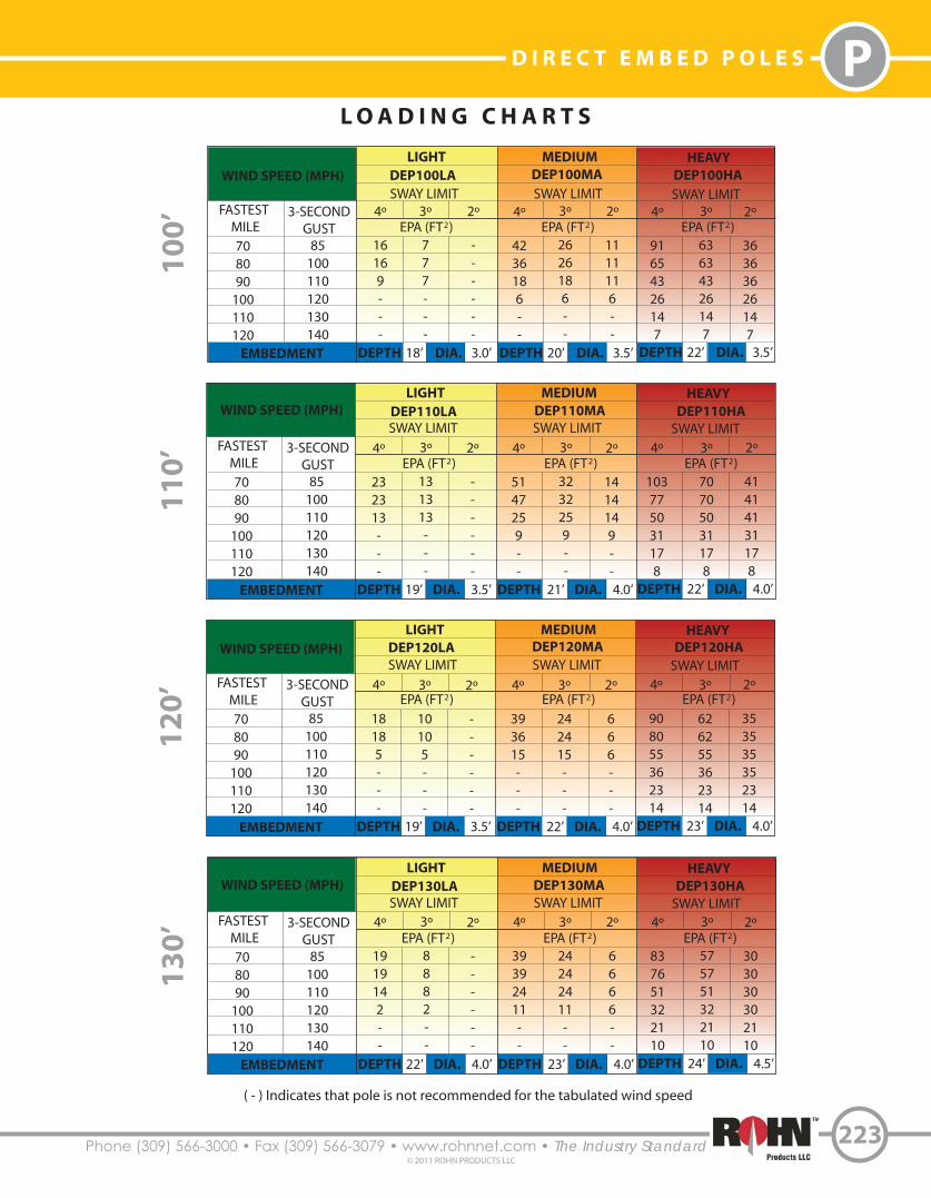
( - ) Indicates that pole is not recommended for the tabulated wind speed
Phone (309) 566-3000 • Fax (309) 566-3079 • www.rohnnet.com • The Industry Standard
P D I R E C T E M B E D P O L E S
224© 2011 ROHN PRODUCTS LLC
L O A D I N G C H A R T S
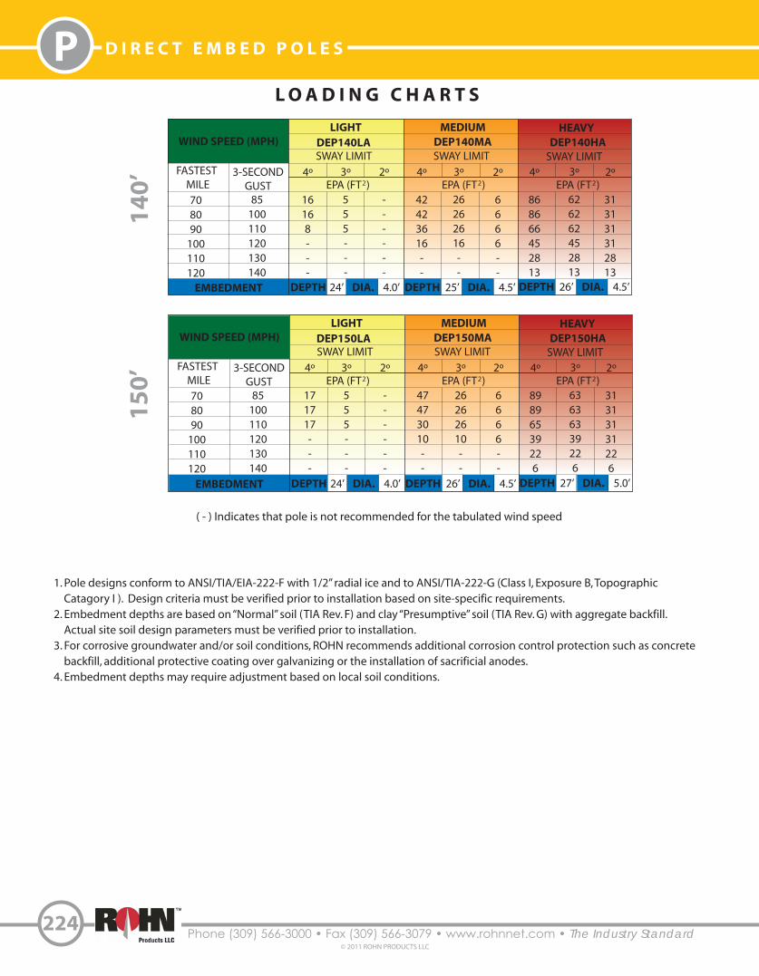
1. Pole designs conform to ANSI/TIA/EIA-222-F with 1/2” radial ice and to ANSI/TIA-222-G (Class I, Exposure B, Topographic Catagory I ). Design criteria must be verified prior to installation based on site-specific requirements. 2. Embedment depths are based on “Normal” soil (TIA Rev. F) and clay “Presumptive” soil (TIA Rev. G) with aggregate backfill. Actual site soil design parameters must be verified prior to installation.3. For corrosive groundwater and/or soil conditions, ROHN recommends additional corrosion control protection such as concrete backfill, additional protective coating over galvanizing or the installation of sacrificial anodes.4. Embedment depths may require adjustment based on local soil conditions.
( - ) Indicates that pole is not recommended for the tabulated wind speed
LIGHT MEDIUM HEAVY
SWAY LIMIT SWAY LIMIT SWAY LIMITWIND SPEED (MPH)
FASTEST MILE
3-SECONDGUST
708090
100110120
85100110120130140
4º
171717---
3º
555---
2º
------
4º
47473010--
3º
26262610--
2º
6666--
4º
89896539226
3º
63636339226
2º
31313131226
15
0’
LIGHT MEDIUM HEAVY
SWAY LIMIT SWAY LIMIT SWAY LIMITWIND SPEED (MPH)
FASTEST MILE
3-SECONDGUST
708090
100110120
85100110120130140
4º
16168---
3º
555---
2º
------
4º
42423616--
3º
26262616--
2º
6666--
4º
868666452813
3º
626262452813
2º
313131312813
14
0’
EMBEDMENT DEPTH DIA.24’ 4.0’ DEPTH DIA.25’ 4.5’ DEPTH DIA.26’ 4.5’
EMBEDMENT DEPTH DIA.24’ 4.0’ DEPTH DIA.26’ 4.5’ DEPTH DIA.27’ 5.0’
EPA (FT )2 EPA (FT )2 EPA (FT )2
DEP140HADEP140MADEP140LA
EPA (FT )2 EPA (FT )2 EPA (FT )2
DEP150HADEP150MADEP150LA
225Phone (309) 566-3000 • Fax (309) 566-3079 • www.rohnnet.com • The Industry Standard© 2011 ROHN PRODUCTS LLC
PD I R E C T E M B E D P O L E S
Pole Height
30’ - 50’
60’ - 100’
110’ - 150’
Part Number
TT050TSP
TT100TSP
TT150TSP
15”
Grounding Lug Ground Wire
Ground RodGround Rod Clamp
Grade
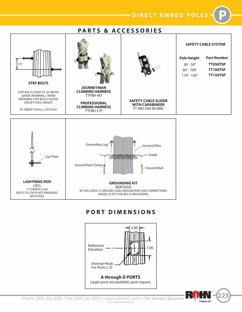
P A R T S & A C C E S S O R I E S
STEP BOLTS
STEP BOLTS START AT 20’ ABOVEGRADE (NOMINAL). WHEN
ORDERING STEP BOLTS, PLEASESPECIFY POLE HEIGHT.
EX. SBDEP120 for a 120’ POLE
JOURNEYMANCLIMBING HARNESS
TTFBH-4D
PROFESSIONALCLIMBING HARNESS
TTFBH-C/P
SAFETY CABLE SLIDERWITH CARABINEERTT-WG-500-W/SMC
SAFETY CABLE SYSTEM
LIGHTNING RODLRCL
5’ COPPER CLADBOLTS TO CAP PLATE, PROVIDED
WITH POLE.
5.00
7.00ReferenceElevation
Internal HookFor Ports C-D
A through D PORTSLarger ports are available, upon request.
P O R T D I M E N S I O N S
Cap Plate
GROUNDING KITBGK5GGX
KIT INCLUDES (1) GROUND LEAD, GROUND ROD AND CONNECTIONS.ORDER (3) KITS FOR REV G GROUNDING.
Phone (309) 566-3000 • Fax (309) 566-3079 • www.rohnnet.com • The Industry Standard
P D I R E C T E M B E D P O L E S
A N T E N N A I N D E X
226© 2011 ROHN PRODUCTS LLC
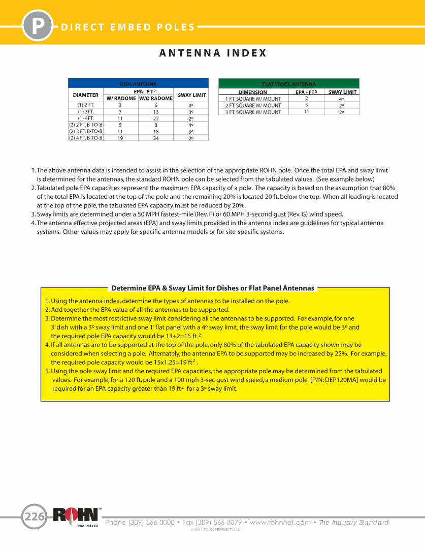
FLAT PANEL ANTENNA
DIMENSION SWAY LIMIT25
11
4º2º2º
EPA - FT1 FT. SQUARE W/ MOUNT2 FT. SQUARE W/ MOUNT3 FT. SQUARE W/ MOUNT
DISH ANTENNA
DIAMETEREPA - FT
SWAY LIMIT
37
115
1119
613228
1834
4º3º2º4º3º2º
W/ RADOME W/O RADOME(1) 2 FT.(1) 3FT.(1) 4FT.
(2) 2 FT. B-TO-B(2) 3 FT. B-TO-B(2) 4 FT. B-TO-B
1. The above antenna data is intended to assist in the selection of the appropriate ROHN pole. Once the total EPA and sway limit is determined for the antennas, the standard ROHN pole can be selected from the tabulated values. (See example below) 2. Tabulated pole EPA capacities represent the maximum EPA capacity of a pole. The capacity is based on the assumption that 80% of the total EPA is located at the top of the pole and the remaining 20% is located 20 ft. below the top. When all loading is located at the top of the pole, the tabulated EPA capacity must be reduced by 20%. 3. Sway limits are determined under a 50 MPH fastest-mile (Rev. F) or 60 MPH 3-second gust (Rev. G) wind speed. 4. The antenna effective projected areas (EPA) and sway limits provided in the antenna index are guidelines for typical antenna systems. Other values may apply for specific antenna models or for site-specific systems.
2 2
1. Using the antenna index, determine the types of antennas to be installed on the pole.2. Add together the EPA value of all the antennas to be supported.3. Determine the most restrictive sway limit considering all the antennas to be supported. For example, for one 3’ dish with a 3º sway limit and one 1’ flat panel with a 4º sway limit, the sway limit for the pole would be 3º and the required pole EPA capacity would be 13+2=15 ft .4. If all antennas are to be supported at the top of the pole, only 80% of the tabulated EPA capacity shown may be considered when selecting a pole. Alternately, the antenna EPA to be supported may be increased by 25%. For example, the required pole capacity would be 15x1.25=19 ft .5. Using the pole sway limit and the required EPA capacities, the appropriate pole may be determined from the tabulated values. For example, for a 120 ft. pole and a 100 mph 3-sec gust wind speed, a medium pole [P/N: DEP120MA] would be required for an EPA capacity greater than 19 ft for a 3º sway limit.
2
2
2
Determine EPA & Sway Limit for Dishes or Flat Panel Antennas


![Sika AnchorFix -2 · PDF fileAnchor dia d [mm] Hole dia d o [mm] Hole depth h o =h ef [mm] Brush size Characteristic distances Min concrete thickness h min [mm] Resin vol [ml] Max](https://img.pdfslide.us/doc/110x75/5a7a26c27f8b9a4b198db337/sika-anchorfix-2-dia-d-mm-hole-dia-d-o-mm-hole-depth-h-o-h-ef-mm-brush-size.jpg)