Embed Size (px)
Citation preview
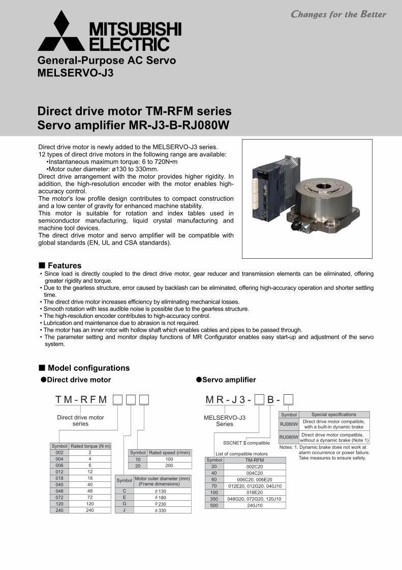
General-Purpose AC Servo MELSERVO-J3
Direct drive motor TM-RFM series Servo amplifier MR-J3-B-RJ080W
Direct drive motor is newly added to the MELSERVO-J3 series. 12 types of direct drive motors in the following range are available:
•Instantaneous maximum torque: 6 to 720N•m •Motor outer diameter: ø130 to 330mm.
Direct drive arrangement with the motor provides higher rigidity. In addition, the high-resolution encoder with the motor enables high- accuracy control. The motor's low profile design contributes to compact construction and a low center of gravity for enhanced machine stability. This motor is suitable for rotation and index tables used in semiconductor manufacturing, liquid crystal manufacturing and machine tool devices. The direct drive motor and servo amplifier will be compatible with global standards (EN, UL and CSA standards).
Features • Since load is directly coupled to the direct drive motor, gear reducer and transmission elements can be eliminated, offering
greater rigidity and torque. • Due to the gearless structure, error caused by backlash can be eliminated, offering high-accuracy operation and shorter settling
time. • The direct drive motor increases efficiency by eliminating mechanical losses. • Smooth rotation with less audible noise is possible due to the gearless structure. • The high-resolution encoder contributes to high-accuracy control. • Lubrication and maintenance due to abrasion is not required. • The motor has an inner rotor with hollow shaft which enables cables and pipes to be passed through. • The parameter setting and monitor display functions of MR Configurator enables easy start-up and adjustment of the servo
system.
Model configurations
Direct drive motor
Servo amplifier
2
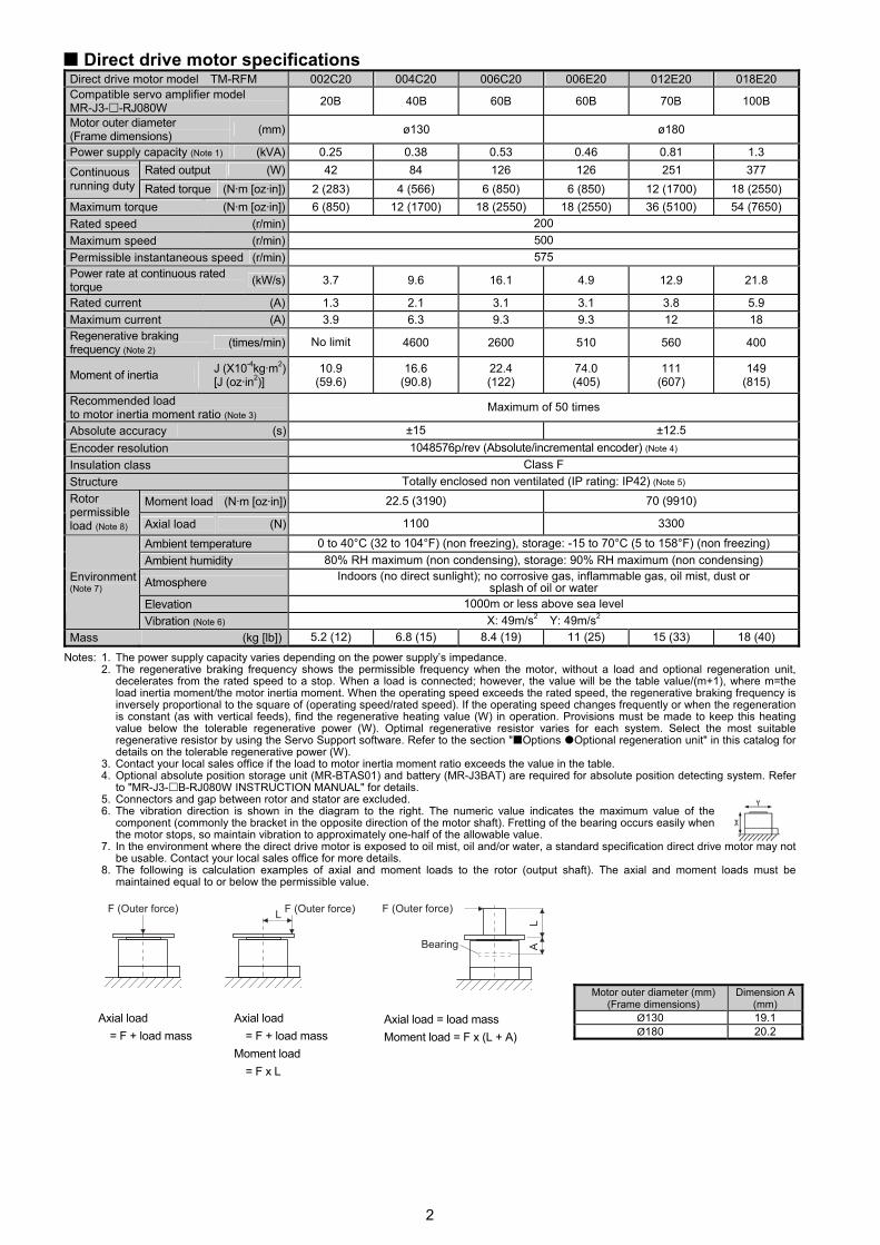
Direct drive motor specifications Direct drive motor model TM-RFM 002C20 004C20 006C20 006E20 012E20 018E20 Compatible servo amplifier model MR-J3- -RJ080W 20B 40B 60B 60B 70B 100B
Motor outer diameter (Frame dimensions) (mm) ø130 ø180
Power supply capacity (Note 1) (kVA) 0.25 0.38 0.53 0.46 0.81 1.3 Rated output (W) 42 84 126 126 251 377 Continuous
running duty Rated torque (N·m [oz·in]) 2 (283) 4 (566) 6 (850) 6 (850) 12 (1700) 18 (2550) Maximum torque (N·m [oz·in]) 6 (850) 12 (1700) 18 (2550) 18 (2550) 36 (5100) 54 (7650) Rated speed (r/min) 200 Maximum speed (r/min) 500 Permissible instantaneous speed (r/min) 575 Power rate at continuous rated torque (kW/s) 3.7 9.6 16.1 4.9 12.9 21.8
Rated current (A) 1.3 2.1 3.1 3.1 3.8 5.9 Maximum current (A) 3.9 6.3 9.3 9.3 12 18 Regenerative braking frequency (Note 2) (times/min) No limit 4600 2600 510 560 400
Moment of inertia J (X10-4kg·m2) [J (oz·in2)]
10.9 (59.6)
16.6 (90.8)
22.4 (122)
74.0 (405)
111 (607)
149 (815)
Recommended load to motor inertia moment ratio (Note 3) Maximum of 50 times
Absolute accuracy (s) ±15 ±12.5 Encoder resolution 1048576p/rev (Absolute/incremental encoder) (Note 4) Insulation class Class F Structure Totally enclosed non ventilated (IP rating: IP42) (Note 5)
Moment load (N·m [oz·in]) 22.5 (3190) 70 (9910) Rotor permissible load (Note 8) Axial load (N) 1100 3300
Ambient temperature 0 to 40°C (32 to 104°F) (non freezing), storage: -15 to 70°C (5 to 158°F) (non freezing) Ambient humidity 80% RH maximum (non condensing), storage: 90% RH maximum (non condensing)
Atmosphere Indoors (no direct sunlight); no corrosive gas, inflammable gas, oil mist, dust or splash of oil or water
Elevation 1000m or less above sea level
Environment (Note 7)
Vibration (Note 6) X: 49m/s2 Y: 49m/s2 Mass (kg [lb]) 5.2 (12) 6.8 (15) 8.4 (19) 11 (25) 15 (33) 18 (40)
Notes: 1. The power supply capacity varies depending on the power supply’s impedance. 2. The regenerative braking frequency shows the permissible frequency when the motor, without a load and optional regeneration unit,
decelerates from the rated speed to a stop. When a load is connected; however, the value will be the table value/(m+1), where m=the load inertia moment/the motor inertia moment. When the operating speed exceeds the rated speed, the regenerative braking frequency is inversely proportional to the square of (operating speed/rated speed). If the operating speed changes frequently or when the regeneration is constant (as with vertical feeds), find the regenerative heating value (W) in operation. Provisions must be made to keep this heating value below the tolerable regenerative power (W). Optimal regenerative resistor varies for each system. Select the most suitable regenerative resistor by using the Servo Support software. Refer to the section " Options Optional regeneration unit" in this catalog for details on the tolerable regenerative power (W).
3. Contact your local sales office if the load to motor inertia moment ratio exceeds the value in the table. 4. Optional absolute position storage unit (MR-BTAS01) and battery (MR-J3BAT) are required for absolute position detecting system. Refer
to "MR-J3- B-RJ080W INSTRUCTION MANUAL" for details. 5. Connectors and gap between rotor and stator are excluded. 6. The vibration direction is shown in the diagram to the right. The numeric value indicates the maximum value of the
component (commonly the bracket in the opposite direction of the motor shaft). Fretting of the bearing occurs easily when the motor stops, so maintain vibration to approximately one-half of the allowable value.
7. In the environment where the direct drive motor is exposed to oil mist, oil and/or water, a standard specification direct drive motor may not be usable. Contact your local sales office for more details.
8. The following is calculation examples of axial and moment loads to the rotor (output shaft). The axial and moment loads must be maintained equal to or below the permissible value.
Axial load = F + load mass
Axial load = F + load mass
Moment load = F x L
Axial load = load mass Moment load = F x (L + A)
Motor outer diameter (mm) (Frame dimensions)
Dimension A (mm)
Ø130 19.1 Ø180 20.2

3
Direct drive motor specifications Direct drive motor model TM-RFM 012G20 048G20 072G20 040J10 120J10 240J10 Compatible servo amplifier model MR-J3- -RJ080W 70B 350B 70B 350B 500B
Motor outer diameter (Frame dimensions) (mm) Ø230 Ø330
Power supply capacity (Note 1) (kVA) 0.71 2.7 3.8 1.2 3.4 6.6 Rated output (W) 251 1005 1508 419 1257 2513 Continuous
running duty Rated torque (N·m [oz·in]) 12 (1700) 48 (6800) 72 (10200) 40 (5660) 120 (17000) 240 (34000)Maximum torque (N·m [oz·in]) 36 (5100) 144 (20400) 216 (30600) 120 (17000) 360 (51000) 720 (102000)Rated speed (r/min) 200 100 Maximum speed (r/min) 500 200 Permissible instantaneous speed (r/min) 575 230 Power rate at continuous rated torque (kW/s) 6.0 37.5 59.3 9.4 40.9 91.4
Rated current (A) 3.4 10.9 16 4.3 11 20 Maximum current (A) 10 33 48 13 33 60 Regenerative braking frequency (Note 2) (times/min) 200 350 250 120 70 40
Moment of inertia J (X10-4kg·m2) [J (oz·in2)]
238 (1300)
615 (3360)
875 (4780)
1694 (9260)
3519 (19200)
6303 (34500)
Recommended load to motor inertia moment ratio (Note 3) Maximum of 50 times
Absolute accuracy (s) ±12.5 ±10 Encoder resolution 1048576p/rev (Absolute/incremental encoder) (Note 4) Insulation class Class F Structure Totally enclosed non ventilated (IP rating: IP42) (Note 5)
Moment load (N·m [oz·in]) 93 (13200) 350 (49600) Rotor permissible load (Note 8) Axial load (N) 5500 16000
Ambient temperature 0 to 40°C (32 to 104°F) (non freezing), storage: -15 to 70°C (5 to 158°F) (non freezing) Ambient humidity 80% RH maximum (non condensing), storage: 90% RH maximum (non condensing)
Atmosphere Indoors (no direct sunlight); no corrosive gas, inflammable gas, oil mist, dust or splash of oil or water
Elevation 1000m or less above sea level
Environment (Note 7)
Vibration (Note 6) X: 49m/s2 Y: 49m/s2 X: 24.5m/s2 Y: 24.5m/s2 Mass (kg [lb]) 17 (38) 36 (80) 52 (115) 53 (120) 91 (205) 146 (325)
Notes: 1. The power supply capacity varies depending on the power supply’s impedance. 2. The regenerative braking frequency shows the permissible frequency when the motor, without a load and optional regeneration unit,
decelerates from the rated speed to a stop. When a load is connected; however, the value will be the table value/(m+1), where m=the load inertia moment/the motor inertia moment. When the operating speed exceeds the rated speed, the regenerative braking frequency is inversely proportional to the square of (operating speed/rated speed). If the operating speed changes frequently or when the regeneration is constant (as with vertical feeds), find the regenerative heating value (W) in operation. Provisions must be made to keep this heating value below the tolerable regenerative power (W). Optimal regenerative resistor varies for each system. Select the most suitable regenerative resistor by using the Servo Support software. Refer to the section " Options Optional regeneration unit" in this catalog for details on the tolerable regenerative power (W).
3. Contact your local sales office if the load to motor inertia moment ratio exceeds the value in the table. 4. Optional absolute position storage unit (MR-BTAS01) and battery (MR-J3BAT) are required for absolute position detecting system. Refer
to "MR-J3- B-RJ080W INSTRUCTION MANUAL" for details. 5. Connectors and gap between rotor and stator are excluded. 6. The vibration direction is shown in the diagram to the right. The numeric value indicates the maximum value of the
component (commonly the bracket in the opposite direction of the motor shaft). Fretting of the bearing occurs easily when the motor stops, so maintain vibration to approximately one-half of the allowable value.
7. In the environment where the direct drive motor is exposed to oil mist, oil and/or water, a standard specification direct drive motor may not be usable. Contact your local sales office for more details.
8. The following is calculation examples of axial and moment loads to the rotor (output shaft). The axial and moment loads must be maintained equal to or below the permissible value.
Axial load = F + load mass
Axial load = F + load mass
Moment load = F x L
Axial load = load mass Moment load = F x (L + A)
Motor outer diameter (mm) (Frame dimensions)
Dimension A (mm)
Ø230 24.4 Ø330 32.5

4
Direct drive motor torque characteristics
Direct drive motor machine accuracy The machine accuracy related to the direct drive motor’s rotor (output shaft) and installation is indicated below:
Item Measured part Accuracy (mm)Runout of flange surface about rotor (output shaft) a 0.05
Runout of fitting outer diameter of flange surface b 0.07 Runout of rotor (output shaft) c 0.04 Runout of rotor (output shaft) end d 0.02

5
Direct drive motor dimensions (Unit: mm) TM-RFM002C20, TM-RFM004C20, TM-RFM006C20
TM-RFM006E20, TM-RFM012E20, TM-RFM018E20
Note: For dimensions where there is no tolerance listed, use general tolerance. The actual dimensions may be 1 to 3mm larger than the dimensions listed. Make allowances for the tolerance when designing a machine.

6
Direct drive motor dimensions (Unit: mm)
TM-RFM012G20, TM-RFM048G20, TM-RFM072G20
TM-RFM040J10, TM-RFM120J10, TM-RFM240J10
Note: For dimensions where there is no tolerance listed, use general tolerance. The actual dimensions may be 1 to 3mm larger than the dimensions listed. Make allowances for the tolerance when designing a machine.
7
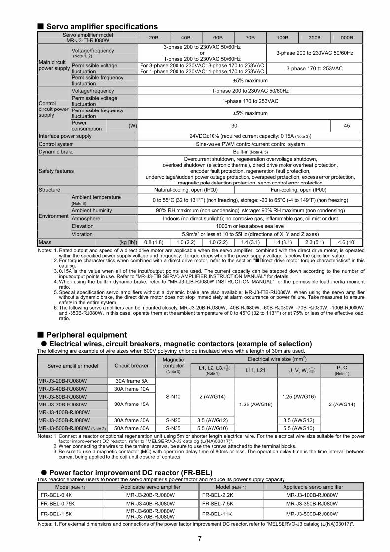
Servo amplifier specifications Servo amplifier model
MR-J3- -RJ080W 20B 40B 60B 70B 100B 350B 500B
Voltage/frequency (Note 1, 2)
3-phase 200 to 230VAC 50/60Hz or
1-phase 200 to 230VAC 50/60Hz 3-phase 200 to 230VAC 50/60Hz
Permissible voltage fluctuation
For 3-phase 200 to 230VAC: 3-phase 170 to 253VACFor 1-phase 200 to 230VAC: 1-phase 170 to 253VAC 3-phase 170 to 253VAC
Main circuit power supply
Permissible frequency fluctuation ±5% maximum
Voltage/frequency 1-phase 200 to 230VAC 50/60Hz Permissible voltage fluctuation 1-phase 170 to 253VAC
Permissible frequency fluctuation ±5% maximum
Control circuit power supply
Power consumption (W) 30 45
Interface power supply 24VDC±10% (required current capacity: 0.15A (Note 3)) Control system Sine-wave PWM control/current control system Dynamic brake Built-in (Note 4, 5)
Safety features
Overcurrent shutdown, regeneration overvoltage shutdown, overload shutdown (electronic thermal), direct drive motor overheat protection,
encoder fault protection, regeneration fault protection, undervoltage/sudden power outage protection, overspeed protection, excess error protection,
magnetic pole detection protection, servo control error protection Structure Natural-cooling, open (IP00) Fan-cooling, open (IP00)
Ambient temperature (Note 6) 0 to 55°C (32 to 131°F) (non freezing), storage: -20 to 65°C (-4 to 149°F) (non freezing)
Ambient humidity 90% RH maximum (non condensing), storage: 90% RH maximum (non condensing) Atmosphere Indoors (no direct sunlight); no corrosive gas, inflammable gas, oil mist or dust Elevation 1000m or less above sea level
Environment
Vibration 5.9m/s2 or less at 10 to 55Hz (directions of X, Y and Z axes) Mass (kg [lb]) 0.8 (1.8) 1.0 (2.2) 1.0 (2.2) 1.4 (3.1) 1.4 (3.1) 2.3 (5.1) 4.6 (10) Notes: 1. Rated output and speed of a direct drive motor are applicable when the servo amplifier, combined with the direct drive motor, is operated
within the specified power supply voltage and frequency. Torque drops when the power supply voltage is below the specified value. 2. For torque characteristics when combined with a direct drive motor, refer to the section " Direct drive motor torque characteristics" in this
catalog. 3. 0.15A is the value when all of the input/output points are used. The current capacity can be stepped down according to the number of
input/output points in use. Refer to "MR-J3- B SERVO AMPLIFIER INSTRUCTION MANUAL" for details. 4. When using the built-in dynamic brake, refer to "MR-J3- B-RJ080W INSTRUCTION MANUAL" for the permissible load inertia moment
ratio. 5. Special specification servo amplifiers without a dynamic brake are also available: MR-J3- B-RU080W. When using the servo amplifier
without a dynamic brake, the direct drive motor does not stop immediately at alarm occurrence or power failure. Take measures to ensure safety in the entire system.
6. The following servo amplifiers can be mounted closely: MR-J3-20B-RJ080W, -40B-RJ080W, -60B-RJ080W, -70B-RJ080W, -100B-RJ080W and -350B-RJ080W. In this case, operate them at the ambient temperature of 0 to 45°C (32 to 113°F) or at 75% or less of the effective load ratio.
Peripheral equipment Electrical wires, circuit breakers, magnetic contactors (example of selection)
The following are example of wire sizes when 600V polyvinyl chloride insulated wires with a length of 30m are used. Electrical wire size (mm2)
Servo amplifier model Circuit breaker Magnetic contactor
(Note 3) L1, L2, L3,
(Note 1) L11, L21 U, V, W, P, C (Note 1)
MR-J3-20B-RJ080W 30A frame 5A MR-J3-40B-RJ080W 30A frame 10A MR-J3-60B-RJ080W MR-J3-70B-RJ080W MR-J3-100B-RJ080W
30A frame 15A S-N10 2 (AWG14) 1.25 (AWG16)
MR-J3-350B-RJ080W 30A frame 30A S-N20 3.5 (AWG12) 3.5 (AWG12) MR-J3-500B-RJ080W (Note 2) 50A frame 50A S-N35 5.5 (AWG10)
1.25 (AWG16)
5.5 (AWG10)
2 (AWG14)
Notes: 1. Connect a reactor or optional regeneration unit using 5m or shorter length electrical wire. For the electrical wire size suitable for the power
factor improvement DC reactor, refer to "MELSERVO-J3 catalog (L(NA)03017)". 2. When connecting the wires to the terminal screws, be sure to use the screws attached to the terminal blocks. 3. Be sure to use a magnetic contactor (MC) with operation delay time of 80ms or less. The operation delay time is the time interval between
current being applied to the coil until closure of contacts.
Power factor improvement DC reactor (FR-BEL) This reactor enables users to boost the servo amplifier’s power factor and reduce its power supply capacity.
Model (Note 1) Applicable servo amplifier Model (Note 1) Applicable servo amplifier FR-BEL-0.4K MR-J3-20B-RJ080W FR-BEL-2.2K MR-J3-100B-RJ080W FR-BEL-0.75K MR-J3-40B-RJ080W FR-BEL-7.5K MR-J3-350B-RJ080W
FR-BEL-1.5K MR-J3-60B-RJ080W MR-J3-70B-RJ080W FR-BEL-11K MR-J3-500B-RJ080W
Notes: 1. For external dimensions and connections of the power factor improvement DC reactor, refer to "MELSERVO-J3 catalog (L(NA)03017)".

8
Standard wiring diagram example
Notes: 1. The forced stop signal is issued for each axis' servo amplifier individually. For overall system apply the emergency stop on the controller
side. 2. The malfunction (ALM) signal (normally closed contact) is conducted to DOCOM in normal alarm-free condition. 3. For details on the controllers, refer to relevant programming manual or user’s manual. 4. Connections for the second and following axes are omitted. 5. Up to 16 axes (n = 1 to 16) can be set using the axis selection rotary switch (SW1). 6. Devices can be assigned for DI1, DI2 and DI3 with controller setting. Refer to the controller’s instruction manuals for details on setting.
These devices can be assigned with the controller, Q173DCPU, Q172DCPU, Q170MCPU, QD75MH or QD74MH. 7. This is for sink wiring. Source wiring is also possible. Refer to "MR-J3- B SERVO AMPLIFIER INSTRUCTION MANUAL" for details. 8. Test operation select switch (SW2-1) is used to perform test operation mode with MR Configurator. SW2-2 is a spare switch. 9. Optional absolute position storage unit (MR-BTAS01) and battery (MR-J3BAT) are required for absolute position detecting system. Refer
to "MR-J3- B-RJ080W INSTRUCTION MANUAL" for details. 10. Manufacture this encoder cable. Refer to "MR-J3- B-RJ080W INSTRUCTION MANUAL" for manufacturing the cable. 11. MR-J3- B-RJ080W servo amplifier and TM-RFM direct drive motor series will be compatible with MRZJW3-SETUP221E software
version C3 or above. 12. Output voltage range varies depending on the monitored signal. 13. The connector type is available for 3.5kW or smaller servo amplifier. For MR-J3-500B-RJ080W, terminal blocks are mounted. Refer to
" Servo amplifier dimensions" in this catalog for details. 14. Refer to programming manual or user’s manual for versions of controller and software compatible with MR-J3- B-RJ080W servo
amplifier.

9
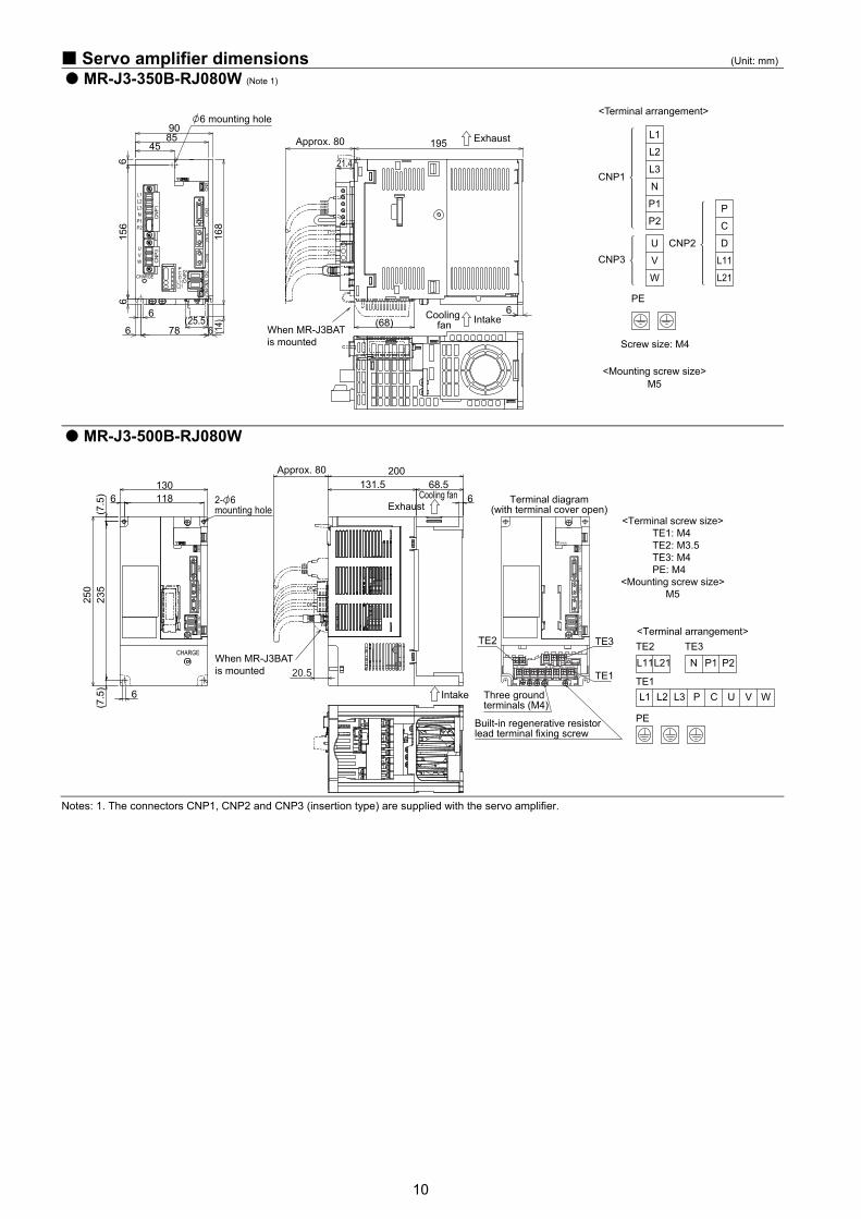
Servo amplifier dimensions (Unit: mm)
MR-J3-20B-RJ080W (Note 1)
MR-J3-40B-RJ080W, MR-J3-60B-RJ080W (Note 1)
MR-J3-70B-RJ080W, MR-J3-100B-RJ080W (Note 1)
Notes: 1. The connectors CNP1, CNP2 and CNP3 (insertion type) are supplied with the servo amplifier.
10
Servo amplifier dimensions (Unit: mm)
MR-J3-350B-RJ080W (Note 1)
MR-J3-500B-RJ080W
Notes: 1. The connectors CNP1, CNP2 and CNP3 (insertion type) are supplied with the servo amplifier.

11
Options Cables and connectors
Item Model IP rating Description
MR-J3-100B-RJ080W or smaller
CN
P1, C
NP2
, CN
P3
(1) Amplifier power supply connector set (Note 3)
MR-J3-350B-RJ080W
(Standard accessory: Insertion type)
–
Notes: 1. Refer to "MR-J3- B-RJ080W INSTRUCTION MANUAL" for manufacturing an encoder cable.
2. Refer to the section " Peripheral equipment Electrical wires, circuit breakers, magnetic contactors (example of selection)" in this catalog for details on example of electrical wire size selection.
3. The connector type is available for 3.5kW or smaller servo amplifier. For MR-J3-500B-RJ080W, terminal blocks are mounted. Refer to " Servo amplifier dimensions" in this catalog for details.
12
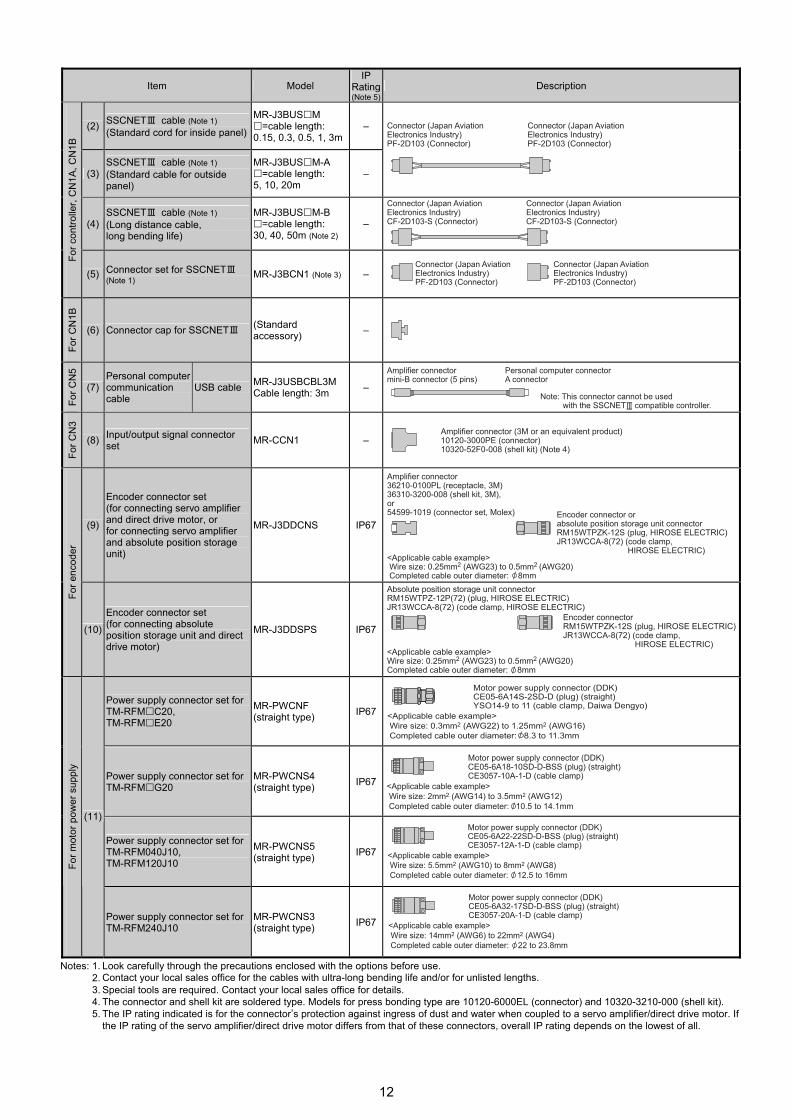
Item Model
IP Rating(Note 5)
Description
(2) SSCNETⅢ cable (Note 1) (Standard cord for inside panel)
MR-J3BUS M =cable length:
0.15, 0.3, 0.5, 1, 3m–
(3) SSCNETⅢ cable (Note 1) (Standard cable for outside panel)
MR-J3BUS M-A =cable length:
5, 10, 20m –
(4) SSCNETⅢ cable (Note 1) (Long distance cable, long bending life)
MR-J3BUS M-B =cable length:
30, 40, 50m (Note 2)–
For c
ontro
ller,
CN
1A, C
N1B
(5) Connector set for SSCNETⅢ (Note 1) MR-J3BCN1 (Note 3) –
For C
N1B
(6) Connector cap for SSCNETⅢ (Standard accessory) –
For C
N5
(7) Personal computer communication cable
USB cable MR-J3USBCBL3M Cable length: 3m –
For C
N3
(8) Input/output signal connector set MR-CCN1 –
(9)
Encoder connector set (for connecting servo amplifier and direct drive motor, or for connecting servo amplifier and absolute position storage unit)
MR-J3DDCNS IP67
For e
ncod
er
(10)
Encoder connector set (for connecting absolute position storage unit and direct drive motor)
MR-J3DDSPS IP67
Power supply connector set forTM-RFM C20, TM-RFM E20
MR-PWCNF (straight type) IP67
Power supply connector set for TM-RFM G20
MR-PWCNS4 (straight type) IP67
Power supply connector set for TM-RFM040J10, TM-RFM120J10
MR-PWCNS5 (straight type) IP67
For m
otor
pow
er s
uppl
y
(11)
Power supply connector set for TM-RFM240J10
MR-PWCNS3 (straight type) IP67
Notes: 1. Look carefully through the precautions enclosed with the options before use.
2. Contact your local sales office for the cables with ultra-long bending life and/or for unlisted lengths. 3. Special tools are required. Contact your local sales office for details. 4. The connector and shell kit are soldered type. Models for press bonding type are 10120-6000EL (connector) and 10320-3210-000 (shell kit). 5. The IP rating indicated is for the connector’s protection against ingress of dust and water when coupled to a servo amplifier/direct drive motor. If
the IP rating of the servo amplifier/direct drive motor differs from that of these connectors, overall IP rating depends on the lowest of all.

13
Options Absolute position storage unit (MR-BTAS01)
This absolute position storage unit is required for configuring absolute position detecting system.
External dimensions (Unit: mm)
Notes: 1. When mounting the absolute position storage unit outside a control panel, be sure to mount the surface A with 4 screws. When mounting
the unit inside a control panel, mounting the surface B with 2 screws is also possible.
Battery (MR-J3BAT) The direct drive motor’s absolute position data can be retained by mounting the battery on the servo amplifier. The battery is not required when the servo system is used in incremental mode.
Appearance
Note: MR-J3BAT is a lithium metal battery. MR-J3BAT is not subject to the dangerous goods (Class 9) of the UN Recommendations.
To transport lithium metal batteries and lithium metal batteries contained in equipment by means of transport subject to the UN Recommendations, take actions to comply with the following regulations: the United Nations Recommendations on the Transport of Dangerous Goods, the Technical Instruction (ICAO-TI) by the International Civil Aviation Organization (ICAO), and the International Maritime Dangerous Goods Code (IMDG Code) by the International Maritime Organization (IMO). To transport the batteries, check the latest standards or the laws of the destination country and take actions. For more information, consult our branch or representative. (As of October 2009)
Optional regeneration unit
Tolerable regeneration power (W) (Note 3)
Optional regeneration unit (Note 1) Servo amplifier
Built-in regenerative
resistor (Note 1)
MR-RB032[40Ω]
MR-RB12[40Ω]
MR-RB30[13Ω]
MR-RB31[6.7Ω]
MR-RB32 [40Ω]
MR-RB50[13Ω] (Note2)
MR-RB51[6Ω]
(Note2)
MR-J3-20B-RJ080W 10 30 100 – – – – – MR-J3-40B-RJ080W 10 30 100 – – – – – MR-J3-60B-RJ080W 10 30 100 – – – – – MR-J3-70B-RJ080W 20 30 100 – – 300 – – MR-J3-100B-RJ080W 20 30 100 – – 300 – – MR-J3-350B-RJ080W 100 – – 300 – – 500 – MR-J3-500B-RJ080W 130 – – – 300 – – 500
Notes: 1. For external dimensions and connections of the built-in regenerative resistor and optional regeneration unit, refer to "MELSERVO-J3 catalog (L(NA)03017)".
2. Be sure to install a cooling fan. The cooling fan must be prepared by user. 3. The power values in this table are resistor-regenerated powers, not rated powers.

14
Warranty
1. Warranty period and coverage
We will repair any failure or defect hereinafter referred to as "failure" in our FA equipment hereinafter referred to as the "Product" arisen during warranty period at no charge due to causes for which we are responsible through the distributor from which you purchased the Product or our service provider. However, we will charge the actual cost of dispatching our engineer for an on-site repair work on request by customer in Japan or overseas countries. We are not responsible for any on-site readjustment and/or trial run that may be required after a defective unit is repaired or replaced.
[Term] The term of warranty for Product is twelve (12) months after your purchase or delivery of the Product to a place designated by you or eighteen (18) months from the date of manufacture whichever comes first ("Warranty Period"). Warranty period for repaired Product cannot exceed beyond the original warranty period before any repair work.
[Limitations]
(1) You are requested to conduct an initial failure diagnosis by yourself, as a general rule. It can also be carried out by us or our service company upon your request and the actual cost will be charged. However, it will not be charged if we are responsible for the cause of the failure.
(2) This limited warranty applies only when the condition, method, environment, etc. of use are in compliance with the terms and conditions and instructions that are set forth in the instruction manual and user manual for the Product and the caution label affixed to the Product.
(3) Even during the term of warranty, the repair cost will be charged on you in the following cases; (i) a failure caused by your improper storing or handling, carelessness or negligence, etc., and a failure caused by your hardware or software
problem (ii) a failure caused by any alteration, etc. to the Product made on your side without our approval (iii) a failure which may be regarded as avoidable, if your equipment in which the Product is incorporated is equipped with a safety device required by
applicable laws and has any function or structure considered to be indispensable according to a common sense in the industry (iv) a failure which may be regarded as avoidable if consumable parts designated in the instruction manual, etc. are duly maintained and replaced (v) any replacement of consumable parts (battery, fan, smoothing capacitor, etc.) (vi) a failure caused by external factors such as inevitable accidents, including without limitation fire and abnormal fluctuation of voltage, and acts of
God, including without limitation earthquake, lightning and natural disasters (vii) a failure generated by an unforeseeable cause with a scientific technology that was not available at the time of the shipment of the Product from
our company (viii) any other failures which we are not responsible for or which you acknowledge we are not responsible for
2. Term of warranty after the stop of production
(1) We may accept the repair at charge for another seven (7) years after the production of the product is discontinued. The announcement of the stop of production for each model can be seen in our Sales and Service, etc.
(2) Please note that the Product (including its spare parts) cannot be ordered after its stop of production. 3. Service in overseas countries
Our regional FA Center in overseas countries will accept the repair work of the Product. However, the terms and conditions of the repair work may differ depending on each FA Center. Please ask your local FA Center for details.
4. Exclusion of responsibility for compensation against loss of opportunity, secondary loss, etc.
Whether under or after the term of warranty, we assume no responsibility for any damages arisen from causes for which we are not responsible, any losses of opportunity and/or profit incurred by you due to a failure of the Product, any damages, secondary damages or compensation for accidents arisen under a specific circumstance that are foreseen or unforeseen by our company, any damages to products other than the Product, and also compensation for any replacement work, readjustment, start-up test run of local machines and the Product and any other operations conducted by you.
5. Change of Product specifications
Specifications listed in our catalogs, manuals or technical documents may be changed without notice. 6. Application and use of the Product
(1) For the use of our General-Purpose AC Servo, its applications should be those that may not result in a serious damage even if any failure or malfunction occurs in General-Purpose AC Servo, and a backup or fail-safe function should operate on an external system to General-Purpose AC Servo when any failure or malfunction occurs.
(2) Our General-Purpose AC Servo is designed and manufactured as a general purpose product for use at general industries. Therefore, applications substantially influential on the public interest for such as atomic power plants and other power plants of electric power companies, and also which require a special quality assurance system, including applications for railway companies and government or public offices are not recommended, and we assume no responsibility for any failure caused by these applications when used. In addition, applications which may be substantially influential to human lives or properties for such as airlines, medical treatments, railway service, incineration and fuel systems, man-operated material handling equipment, entertainment machines, safety machines, etc. are not recommended, and we assume no responsibility for any failure caused by these applications when used. We will review the acceptability of the abovementioned applications, if you agree not to require a specific quality for a specific application. Please contact us for consultation.

15
Memo

Safety Warning To ensure proper use of the products listed in this catalog,
please be sure to read the instruction manual prior to use.
L(NA)03051ENG A 0910 Printed in Japan (MDOC) New publication, effective October 2009 Specifications subject to change without notice.