Embed Size (px)
Citation preview
Project Title 23 09 23 - 1 Direct-Digital Control System for HVAC
DIRECT-DIGITAL CONTROL SYSTEM FOR HVAC
PART 1 GENERAL 1.01 SUMMARY
A. The building shall have a direct digital control (DDC) energy management system (EMS) to achieve precise control of all Heating, Ventilating, and Air Conditioning (HVAC) systems and provide the means to standardize control functions with energy saving strategies. The DDC shall fully integrate with the existing building management system (BMS) workstation located at the Metropolitan Nashville Public Schools Facility & Grounds Maintenance Department, 1417 Murfreesboro Pike, Nashville, TN 37217. It is intended that all newly constructed buildings be controlled using standalone microprocessor, web-based, BACnet-compliant DDC computer systems. All hardware, software, and miscellaneous equipment required to insure that the EMS can be managed from MNPS’ local area network (LAN) shall be provided as a part of the project. The HVAC controls contractor (henceforth referred to as the “Contractor”) shall be responsible for all low-voltage wiring installation and must coordinate networking with MNPS’ Technology Information Services (TIS) department.
1. Any required changes or updates to the existing workstation hardware/software necessary to meet the
requirements stated within this specification.
B. The approved manufacturer is Honeywell Building Control Systems, which is located at 1985 Douglas Drive North, Minneapolis, MN 55422. Other equivalent systems must be submitted to MNPS (henceforth referred to as the “Owner”) for approval.
1. The Contractor may only sub-contract electrical wiring and field device installation to a locally-licensed
electrical contractor specializing in controls. Only full-time permanent employees of the Contractor shall be used to design, program, commission, train, and service the EMS; and, work must be performed in compliance with BACnet Testing Laboratories or LonMark International.
C. The EMS shall provide remote access for control and monitoring of the building systems. The EMS shall be set
up to allow alarms or faults to be emailed and/or texted to various MNPS email recipients as set forth per the Owner. The Contractor shall coordinate wiring and cabling with MNPS TIS.
D. The Contractor shall furnish all labor, materials, and equipment necessary for a complete and operating EMS
to control the new and existing HVAC equipment, to include, but not limited to: heat pumps, air handlers, variable air volumes, variable refrigerant flows, air conditioners, fan coil units, central plants, and relays shown on the contract drawings; utilizing DDCs as shown on the drawings and as described herein. Drawings are diagrammatic only. All controllers furnished per this section shall communicate on a peer-to-peer bus over an open protocol bus (e.g.: LonTalk, BACnet).
E. The intent of this specification is to provide a system that is consistent with EMSs throughout the Owner’s
facilities running on the Tridium Niagara 4 platform.
1. Controllers with newest available firmware or features to ensure compatibility are required.
F. Installation
1. The Contractor shall furnish and install all necessary hardware, computing equipment, and software as defined in this specification.
2. Electrical control wiring and terminations for the EMS shall be provided by the Contractor. In addition,
electrical work specified herein shall be the responsibility of the Contractor. The Contractor must accept responsibility for total system operation in a neat and workmanlike manner.
a. Line-voltage wiring to be provided by electrical contractor.
Project Title 23 09 23 - 2 Direct-Digital Control System for HVAC
3. Wiring shall be installed in accordance with the requirements for low voltage controls as specified in
the electrical specifications. Local codes shall have jurisdiction.
4. All system components shall be fault-tolerant, satisfactorily operating without damage between 85% and 110% of rate voltage and at plus/minus three [3] hertz variation in line frequency. Transient voltage surge suppression shall be incorporated in the design of the EMS to protect all DDCs and local unit controllers from power spikes.
5. All material and equipment used shall be standard components, regularly manufactured and available,
and not custom-designed especially for this project. All systems and components, except site-specific software, shall have previously been thoroughly tested and proved in actual use prior to installation on this project.
6. The system architecture shall be fully modular, permitting expansion of application software, system
peripherals, and site controllers.
7. The EMS, upon completion of installation and prior to acceptance of the project, shall perform all operating functions as detailed in this specification. Alarm distribution methods (e-mail, SMS, etc.) and destinations (address, phone, printer, etc.) will be defined at the point-to-point inspection or earlier only by request in writing from the Contractor to the Owner’s authorized representative.
1.02 REFERENCES
A. ASHRAE Handbook – Fundamentals, 2009
B. TIA-232-F Interface Between Data Terminal Equipment and Data Circuit-Terminating Equipment Employing Serial Binary Data Interchange (RS-232), 1997
C. ANSI/TIA/EIA-422-B Electrical Characteristics of Balanced Voltage Differential Interface Circuits (RS-422),
1994
D. NEMA Coaxial Communication Cable (CATV), 1978
E. NEMA Industrial Controls and Sensors (ICS-3), 1978
F. NEMA-250 Enclosures for Electrical Equipment (1,000V Maximum), 1979
G. NFPA-70 National Electric Code (NEC), 1991
H. NFPA-90A Installation of Air-Conditioning and Ventilating Systems, 1978 PART 2 PRODUCTS 2.01 SYSTEM DESCRIPTION
A. The EMS shall be capable of integrating multiple building functions, including equipment supervision and control, alarm management, energy management, and historical data collection and archiving.
B. The EMS shall consist of HTML5 elements to optimize the latest multimedia across various mobile platforms.
C. The EMS shall consist of standalone DDCs.
D. The EMS shall be modular in nature and shall permit expansion of both capacity and functionality through the
addition of sensors, actuators, DDCs, and user-devices.
Project Title 23 09 23 - 3 Direct-Digital Control System for HVAC
E. The EMS shall be Internet-based.
F. System architectural design shall eliminate dependence upon any single device for alarm reporting and control execution. Each DDC panel shall operate independently by performing its own specified control, alarm management, user input/output (I/O), and historical data collection. Failure of any single component or network connection shall not interrupt the execution of control strategies at other operational devices.
G. Standalone DDCs shall be able to access any data for, or send control commands and alarm reports directly to
any other DDC or combination of panels on the network without dependence upon a control processing devices. Standalone DDCs shall be able to send alarm reports to multiple user workstations without dependence upon a central processing device.
H. System shall be connected to the Owner’s BMS using a peer-to-peer bus over an open protocol bus (i.e.:
Ethernet).
I. All EMS communications shall reside on the Owner’s LAN and all software shall reside on the Owner’s BMS server.
2.02 COMMUNICATION NETWORKING
A. The design of the EMS network architecture and standalone DDCs shall consist of two levels:
1. A high-performance BACnet/IP.
2. A standard BACnet MS/TP.
3. LonTalk
B. Access to system data shall not be restricted by the DDC configuration of the EMS. The DDC configuration shall be totally transparent when accessing data or developing control programs.
C. Communications shall be provided to allow DDCs to communicate with the workstation and/or via remote
access over VPN at all times. D. Ethernet via an RJ-45 jack at the site will be provided via the Owner’s TIS department. Specifications as far as
location and special quantity requests shall be made in writing to the Owner’s authorized representative. 2.03 SYSTEM NETWORK CONTROLLER
A. These controllers (JACE 8000) are designed to manage communications between the programmable equipment controllers (PEC), application specific controllers (ASC), and advanced unitary controllers (AUC) which are connected to its communications trunks, manage communications between itself and other system network controllers (SNC) and with any operator workstations (OWS) that are part of the EMS, and perform control and operating strategies for the system based on information from any controller connected to the EMS.
B. The controllers shall be fully programmable to meet the unique requirements of the facility it shall control. C. The controllers shall be capable of peer-to-peer communications with other SNCs and with any OWS connected
to the EMS, whether the OWS is directly connected, connected via cellular modem, or connected via the Internet.
D. The communication protocols utilized for peer-to-peer communications between SNCs will be Niagara 4 Fox,
BACnet TCP/IP, and SNMP. Use of a proprietary communication protocol for peer-to-peer communications between SNCs is not allowed.
E. The SNC shall employ a device count capacity license model that supports expansion capabilities.
Project Title 23 09 23 - 4 Direct-Digital Control System for HVAC
F. The SNC shall be enabled to support and shall be licensed with the following open protocol drivers (client and
server) by default:
1. BACnet
2. LonTalk
3. MODBUS
4. SNMP
5. KNX
G. The SNC shall be capable of executing application control programs to provide:
1. Calendar functions.
2. Scheduling.
3. Trending.
4. Alarm monitoring and routing.
5. Time synchronization.
6. Integration of LonTalk, BACnet, and MODBUS controller data.
7. Network management functions for all SNC, PEC, and ASC based devices.
H. The SNC shall provide the following hardware features at a minimum:
1. Two [2] 10/100 megabits per second Ethernet ports.
2. Two [2] isolated RS-485 ports with biasing switches.
3. One [1] gigabyte random access memory (RAM).
4. Two [2] gigabyte user storage & four [4] gigabyte total flash storage.
5. Wi-Fi (client or wireless access point).
6. Universal serial bus (USB) flash drive.
7. High-speed field bus expansion.
8. Negative twenty [20] degrees Celsius to sixty [60] degrees Celsius operating temperature range.
9. Integrated twenty-four [24] volt (V) alternating/direct current (AC/DC) global power supply.
10. MicroSD memory card employing encrypted safe boot technology.
I. The SNC shall support standard web browser access via the Intra/Internet. It shall support a minimum of sixteen [16] simultaneous users.
Project Title 23 09 23 - 5 Direct-Digital Control System for HVAC
J. The SNC shall provide alarm recognition, storage, routing, management, and analysis to supplement distributed capabilities of equipment or application specific controllers.
K. The SNC shall be able to route any alarm condition to any defined user location whether connected to a local
network or remote via cellular modem, or wide-area network.
1. Alarm generation shall be selectable for annunciation type and acknowledgement requirements including, but not limited to:
a. Alarm.
b. Return to normal.
c. To default.
2. Alarms shall be annunciated in any of the following manners as defined by the user:
a. Screen message text.
b. E-mail of complete alarm message to multiple recipients.
c. Pagers via paging services that initiate a page on receipt of e-mail message.
d. Graphics with flashing alarm object(s).
3. The following shall be recorded by the SNC for each alarm, at a minimum:
a. Time and date.
b. Equipment (air handler number, access way, etc.).
c. Acknowledge time, date, and user who issued acknowledgement.
L. Programming software and all controller setup “wizards” shall be embedded into the SNC.
M. The SNC shall support the following security functions:
1. Module code signing to verify the author of programming tool and confirm that the code has not been
altered or corrupted.
2. Role-based access control (RBAC) for managing user roles and permissions.
3. Require users to use strong credentials.
4. Data in motion and sensitive data at rest be encrypted.
5. Lightweight directory access protocol and Kerberos integration of access management.
N. The SNC shall support the following data modeling structures to utilize search, hierarchy, template, and permission functionality:
1. Descriptive metadata tags to define the structure of properties.
2. Tagging process to apply metadata to components.
3. Tag dictionary.
Project Title 23 09 23 - 6 Direct-Digital Control System for HVAC
O. The SNC shall employ template functionality. Templates are a containerized set of configured data tags,
graphics, histories, and alarms that are set to be deployed as a unit based upon manufacturer’s controller and relationships. All lower level communicating controllers (PEC, AUC, advanced variable air volume controller, and variable frequency drive) shall have an associated template file for reuse on future project additions.
P. The SNC shall be provided with a five [5] year software maintenance license. Labor to implement not included.
Q. Standalone DDCs shall be microprocessor-based. They shall also be multi-tasking, multi-user, real-time digital
control processors consisting of modular hardware with plug-in enclosed processors, communication capabilities, power suppliers, and I/O point modules. DDC size shall be sufficient to fully meet the requirements of this specification, point list, and/or sequence of operations.
R. Each DDC shall have sufficient memory to support its own operating system and databases, plus a minimum
of twenty-five [25] percent expansion, including:
1. Energy management applications.
2. Alarm management applications including custom messages for each level of alarm for each point in the system.
3. Historical/trending data for points specified.
4. Maintenance support applications.
5. Custom processes.
6. Operator I/O.
S. Provide and install labels on all thermostats and DDCs with point name/address association.
T. In the event of loss of normal power, there shall be an orderly shutdown of all DDCs to prevent the loss of
application or database software. Non-volatile memory shall be incorporated for all critical controller configuration data and battery backup or a shutdown capacitor shall be provided to support the real-time clock and all volatile memory for a minimum of twenty [20] days.
1. Upon restoration of normal power, the DDCs shall automatically resume full operation without manual
intervention.
2. Should a DDC’s memory be lost for any reason, the user shall have the capability of reloading the DDC via the local port or a networked OWS.
3. Upon restoration of normal power, the DDCs shall automatically stage all equipment or zones to on
with a twenty [20] second delay between each until full operation has resumed.
U. Uninterruptible power supply and surge protection required.
1. JACE 6Es must be installed with battery backup. 2.04 PROGRAMMABLE EQUIPMENT CONTROLLER
A. HVAC control shall be accomplished using LonWorks or BACnet based devices where the application has a LonMark profile or BTL listed protocol implementation conformance statement (PICS) defined. Where LonMark devices are not available for a particular application, devices based on LonWorks shall be acceptable. For each LonWorks device that does not have LonMark certification, the device supplier shall provide an XIF file for the device. The controller platform shall provide options and advanced system functions, programmable and
Project Title 23 09 23 - 7 Direct-Digital Control System for HVAC
configurable using the Niagara 4 Framework, that allow standard and customizable control solutions required in executing the sequence of operation.
B. All PECs shall be application programmable and shall at all times maintain their certification. All control
sequences within or programmed into the PEC shall be stored in non-volatile memory, which is not dependent upon the presence of a battery to be retained.
C. The PEC shall provide light emitting diode (LED) indication of communication and controller performance to the
technician, without cover removal.
D. The PEC shall not require any external configuration tool or programming tool. All configuration and programming tasks shall be accomplished and accessible from within the Niagara 4 environment.
E. The following integral and remote I/Os shall be supported per each PEC:
1. Eight [8] integral dry contact digital inputs.
2. Any two [2] digital inputs (DIs) may be configured as pulse counters with a maximum pulse read rate
of fifteen [15] hertz.
3. Eight [8] integral analog inputs (configurable as zero [0] to ten [10] V, zero [0] to ten thousand [10,000] Ohms, or twenty thousand [20,000] negative temperature coefficient).
4. Six [6] integral four [4] to twenty [20] milliamperes (mA) analog outputs (AOs).
5. Eight [8] integral twenty-four [24] VAC triode for alternating current (TRIAC) digital outputs (Dos),
configurable as maintained or floating motor control outputs.
6. One [1] integral twenty [20] VDC sixty-five [65] mA power supply for auxiliary devices.
7. If a twenty [20] VDC sixty-five [65] mA power supply terminal is not integral to the PEC, provide at each PEC a separate, fully isolated, enclosed, current limited, and regulated nationally recognized testing laboratory listed auxiliary power supply for power to auxiliary devices.
F. Each PEC shall have expansion ability to support additional I/O requirements through the use of remote I/O
modules.
G. PECs shall support the following control techniques, at a minimum:
1. General purpose control loops that can incorporate demand limit control strategies, setpoint reset, adaptive intelligent recovery, and time of day bypass.
2. General purpose, nonlinear control loops.
3. Start/stop loops.
4. If/then/else logic loops.
5. Math function loops (minimum, maximum, average, summate, subtract, squareroot, multiply, divide,
and enthalpy). 2.05 ADVANCED UNITARY CONTROLLER
A. The AUC platform shall be designed specifically to control HVAC, to include ventilation, filtration, heating, cooling, humidification, and distribution. Equipment includes constant volume air handlers, variable air volume air handlers, packaged rooftop units, heat pumps, unit ventilators, fan coils, natural convection units, and radiant
Project Title 23 09 23 - 8 Direct-Digital Control System for HVAC
panels. The control shall use LonMark or BACnet based devices where the application has a LonMark profile or BTL listed PICS defined. Where LonMark devices are not available for a particular application, devices based on LonWorks shall be acceptable. For each LonWorks device that does not have LonMark certification, the device supplier shall provide an XIF file for the device. The controller platform shall provide options and advanced system functions, programmable and configurable using the Niagara 4 Framework, that allow standard and customizable control solutions required in executing the sequence of operation.
B. Controller shall have the following minimum requirements:
1. Be fully programmable with full functionality on any Niagara 4 brand platform.
a. Support downloads to the controller from any brand of Niagara 4 platform.
b. Support uploads from the controller to any brand of Niagara 4 platform.
c. Support simulation/debug mode of the controller.
d. Maintain native graphical user interface.
e. Native function block programming software and all controller setup “wizards” shall be
embedded within the Niagara 4 environment.
2. Controller shall be capable of either integrating with other devices or standalone operation.
3. Controller shall have two [2] microprocessors. The host processor contains on chip flash program memory, flash information memory, and RAM to run the main HVAC application. The second processor for network communications. Controller memory minimum requirements include:
a. Flash memory capacity of sixty [60] kilobytes with eight [8] kilobytes for application program.
b. Flash memory setting retained for ten [10] years.
c. RAM of two [2] kilobytes.
4. Controller shall have an internal time clock with the ability to automatically revert from a master time
clock on failure.
a. Operating range of twenty-four [24] hours, three hundred sixty-five [365] days, multi-year calendar including day of week and configuration for automatic daylight saving time adjustment to occur on configured start and stop dates.
b. Accuracy of one [1] minute per month at seventy-two [72] degrees Fahrenheit (F).
c. Power failure backup of twenty-four [24] hours between thirty-two [32] degrees F and one
hundred [100] degrees F.
5. Controller shall have significant event notification, periodic update capability, and failure detect when network inputs fail to be detected within their configurable time frame.
6. Controller shall have an internal DC power supply to power external sensors.
a. Power output of twenty [20] VDC plus/minus ten [10] percent at seventy-five [75] mA.
7. Controller shall have a visual LED indication of the status of the device:
a. Controller operating normally.
Project Title 23 09 23 - 9 Direct-Digital Control System for HVAC
b. Controller in process of download.
c. Controller in manual mode under control of software tool.
d. Controller lost its configuration.
e. No power to controller, low voltage, or controller damage.
f. Processor and/or controller are not operating.
8. Ambient operating and storage environmental temperature ratings of negative forty [-40] degrees F to
one hundred fifty-five [155] degrees F.
9. Controller shall meet the requirements of Federal Communications Commission Part 15, Subpart B, Class B (radiated emissions).
10. The controller housing shall be plenum rated mounting to either a panel or DIN rail.
11. The controller shall have a mix of DIs, TRIAC DOs, AOs, and universal inputs (UIs).
a. AOs shall be capable of being configured as Dos.
b. I/O terminal strips shall be removable from the controller without disconnecting wiring.
c. I/O terminals shall be designated with color-coded labels.
d. UIs shall be capable of being configured as binary inputs, resistive inputs, voltage inputs, or
current inputs.
12. The controller shall provide continuous automated loop tuning with an adaptive integral algorithm control loop.
13. The controller platform shall have standard HVAC application programs that are modifiable to support
both traditional and specialized sequences of operation:
a. Discharge air control and low limit.
b. Pressure dependent dual duct without flow mixing.
c. Variable air volume with return flow tracking.
d. Economizer with differential enthalpy.
e. Minimum airflow coordinated with carbon dioxide.
f. Unit ventilator cycle (1, 2, 3) 2-pipe.
g. Unit ventilator cycle (1, 2, 3) 2-pipe with face/bypass.
h. Unit ventilator cycle (1, 2, 3) 4-pipe.
i. Unit ventilator cycle (1, 2, 3) 4-pipe with electronic overspeed control valve. 2.06 DIRECT DIGITAL CONTROLLER RESIDENT SOFTWARE FEATURES
Project Title 23 09 23 - 10 Direct-Digital Control System for HVAC
A. DDCs shall include all point I/Os necessary to perform the specified control sequences Switches shall be mounted either within the DDC’s key-accessed enclosure, or externally mounted. In addition, each switch position shall be supervised in order to inform the system that automatic control has been overridden. Contractor shall provide a minimum of five [5] percent spare points of each type via additional point termination boards or controllers.
B. Local alarming and trending capabilities shall be provided for convenient troubleshooting and system
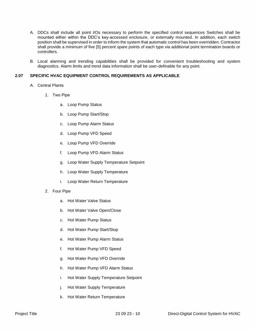
diagnostics. Alarm limits and trend data information shall be user-definable for any point. 2.07 SPECIFIC HVAC EQUIPMENT CONTROL REQUIREMENTS AS APPLICABLE
A. Central Plants
1. Two Pipe
a. Loop Pump Status
b. Loop Pump Start/Stop
c. Loop Pump Alarm Status
d. Loop Pump VFD Speed
e. Loop Pump VFD Override
f. Loop Pump VFD Alarm Status
g. Loop Water Supply Temperature Setpoint
h. Loop Water Supply Temperature
i. Loop Water Return Temperature
2. Four Pipe
a. Hot Water Valve Status
b. Hot Water Valve Open/Close
c. Hot Water Pump Status
d. Hot Water Pump Start/Stop
e. Hot Water Pump Alarm Status
f. Hot Water Pump VFD Speed
g. Hot Water Pump VFD Override
h. Hot Water Pump VFD Alarm Status
i. Hot Water Supply Temperature Setpoint
j. Hot Water Supply Temperature
k. Hot Water Return Temperature
Project Title 23 09 23 - 11 Direct-Digital Control System for HVAC
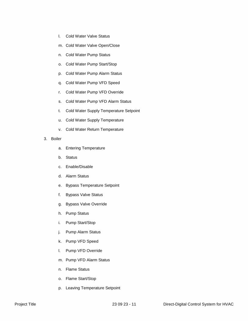
l. Cold Water Valve Status
m. Cold Water Valve Open/Close
n. Cold Water Pump Status
o. Cold Water Pump Start/Stop
p. Cold Water Pump Alarm Status
q. Cold Water Pump VFD Speed
r. Cold Water Pump VFD Override
s. Cold Water Pump VFD Alarm Status
t. Cold Water Supply Temperature Setpoint
u. Cold Water Supply Temperature
v. Cold Water Return Temperature
3. Boiler
a. Entering Temperature
b. Status
c. Enable/Disable
d. Alarm Status
e. Bypass Temperature Setpoint
f. Bypass Valve Status
g. Bypass Valve Override
h. Pump Status
i. Pump Start/Stop
j. Pump Alarm Status
k. Pump VFD Speed
l. Pump VFD Override
m. Pump VFD Alarm Status
n. Flame Status
o. Flame Start/Stop
p. Leaving Temperature Setpoint
Project Title 23 09 23 - 12 Direct-Digital Control System for HVAC
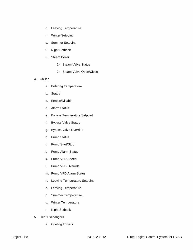
q. Leaving Temperature
r. Winter Setpoint
s. Summer Setpoint
t. Night Setback
u. Steam Boiler
1) Steam Valve Status
2) Steam Valve Open/Close
4. Chiller
a. Entering Temperature
b. Status
c. Enable/Disable
d. Alarm Status
e. Bypass Temperature Setpoint
f. Bypass Valve Status
g. Bypass Valve Override
h. Pump Status
i. Pump Start/Stop
j. Pump Alarm Status
k. Pump VFD Speed
l. Pump VFD Override
m. Pump VFD Alarm Status
n. Leaving Temperature Setpoint
o. Leaving Temperature
p. Summer Temperature
q. Winter Temperature
r. Night Setback
5. Heat Exchangers
a. Cooling Towers
Project Title 23 09 23 - 13 Direct-Digital Control System for HVAC
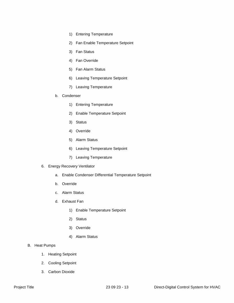
1) Entering Temperature
2) Fan Enable Temperature Setpoint
3) Fan Status
4) Fan Override
5) Fan Alarm Status
6) Leaving Temperature Setpoint
7) Leaving Temperature
b. Condenser
1) Entering Temperature
2) Enable Temperature Setpoint
3) Status
4) Override
5) Alarm Status
6) Leaving Temperature Setpoint
7) Leaving Temperature
6. Energy Recovery Ventilator
a. Enable Condenser Differential Temperature Setpoint
b. Override
c. Alarm Status
d. Exhaust Fan
1) Enable Temperature Setpoint
2) Status
3) Override
4) Alarm Status
B. Heat Pumps
1. Heating Setpoint
2. Cooling Setpoint
3. Carbon Dioxide
Project Title 23 09 23 - 14 Direct-Digital Control System for HVAC
4. Outside Air Damper Override
5. Supply Air Fan Status
6. Supply Air Fan Start/Stop
7. Discharge Air Fan Alarm Status
8. Discharge Air Temperature
9. Space Temperature Setpoint Dial
10. Space Temperature Setpoint Minimum
11. Space Temperature Setpoint Maximum
12. Unoccupied Heating Setpoint
13. Unoccupied Cooling Setpoint
C. Air Handling Unit
1. Supply Air Temperature Setpoint
2. Static Pressure
3. Static Pressure Setpoint
4. Return Air Temperature
5. Return Air Fan Status
6. Return Air Fan Start/Stop
7. Return Air Fan Speed
8. Return Air Fan Alarm Status
9. Relief Damper Override
10. Mixed Air Damper Override
11. Mixed Air Temperature Setpoint
12. Mixed Air Temperature
13. Outside Air Damper Override
14. Hot Water Valve Override
15. Cold Water Valve Override
16. Supply Air Fan Status
17. Supply Air Fan Start/Stop
Project Title 23 09 23 - 15 Direct-Digital Control System for HVAC
18. Supply Air Fan Speed
19. Supply Air Fan Alarm Status
20. Supply Air Temperature
D. Variable Air Volume Box
1. Supply Air Temperature
2. Space Temperature
3. Heating Setpoint
4. Cooling Setpoint
5. Minimum Cubic Feet Per Minute
6. Maximum Cubic Feet Per Minute
7. Cubic Feet Per Minute
8. Maximum Carbon Dioxide
9. Carbon Dioxide
10. Relative Humidity
11. Damper Override
12. Space Temperature Setpoint Dial
13. Space Temperature Setpoint Minimum
14. Space Temperature Setpoint Maximum
15. Unoccupied Heating Setpoint
16. Unoccupied Cooling Setpoint
17. Reheat Valve Override
18. Discharge Air Temperature
E. Fan Coil Unit
1. Return Air Temperature
2. Heating Setpoint
3. Cooling Setpoint
4. Outside Air Damper Override
5. Mode
Project Title 23 09 23 - 16 Direct-Digital Control System for HVAC
6. Mode Override
7. Valve Override
8. Discharge Air Fan Status
9. Discharge Air Fan Start/Stop
10. Discharge Air Fan Speed
11. Discharge Air Fan Alarm Status
12. Discharge Air Temperature
13. Relative Humidity
14. Carbon Dioxide
15. Space Temperature Setpoint Dial
16. Space Temperature Setpoint Minimum
17. Space Temperature Setpoint Maximum
18. Unoccupied Heating Setpoint
19. Unoccupied Cooling Setpoint
F. Variable Refrigerant Flow
1. Space Temperature
2. Heating Setpoint
3. Cooling Setpoint
4. Mode
5. Alarm Status
6. Filter Status
7. Carbon Dioxide
8. Relative Humidity
9. Space Temperature Setpoint Dial
10. Space Temperature Setpoint Minimum
11. Space Temperature Setpoint Maximum
12. Unoccupied Heating Setpoint
13. Unoccupied Cooling Setpoint
Project Title 23 09 23 - 17 Direct-Digital Control System for HVAC
14. Discharge Air Temperature
15. Discharge Air Fan Status
16. Discharge Air Fan Start/Stop
17. Discharge Air Fan Speed
18. Discharge Air Fan Alarm Status
19. Discharge Air Fan Direction
PART 3 EXECUTION 3.01 GENERAL
A. The following basic control strategies are common to all EMSs:
1. Start/stop
a. Timed
1) Holiday overrides
2) Event overrides
b. Optimized
2. Unoccupied/night setbacks based upon average temperatures
3. Alarms for out of range temperatures
4. Staggered start of high demand HVAC equipment and/or zones with multiples pieces of HVAC equipment
5. Trending
6. Outside air and carbon dioxide readings and control per ASHRAE recommendations
a. Outside air sensor shall be securely mounted on the North side of a building wall in a safe
location protected from adverse weather or vandalism.
1) If the building is not aligned with the Cardinal Directions, orient the photocell to the Northeast for buildings aligned with the Equal Divisions, or as close to possible to North but between North and Northeast for all other alignments.
7. Economizer (fee-cooling) advantage where HVAC equipment permits
B. Graphics, links, designs, and drawings necessary to provide a user-friendly interface.
1. Examples of graphics may be requested from the Owner’s authorized representative for review to
ensure they are consistent between projects.
C. Enclosures in which to securely mount monitoring devices.
Project Title 23 09 23 - 18 Direct-Digital Control System for HVAC
D. Removal of all abandoned controls, wiring, panels, etc.
E. Metal cabinet keyed to match control panels for documentation storage, twist timer overrides, etc.
F. Provide hot and chilled water supply and return temperatures that are integral to HVAC system. Ensure safe operating temperatures before enabling or operating HVAC equipment.
G. Provide variable frequency drive (VFD) reset any time VFD is placed in hand/override to ensure VFD always
starts at zero [0] hertz in auto position.
H. Discharge air temperature shall be provided on all pieces of HVAC equipment.
I. Consider security on any commonly recycled non-ferrous metals outside the building envelope. 3.02 INTERFACE WITH OTHER WORK
A. A project supervisor shall be assigned to coordinate all aspects of the project installation. The supervisor shall be a direct employee of the authorized Contractor. The supervisor shall be factory-trained in control technology, systems installation, and commissioning software-based systems.
B. The mechanical subcontractor shall install all wells, pressure tappings, and tappings for flow sensors.
1. For controls only projects, this work shall be provided by the Contractor.
C. Patching and painting required for the installation will be accomplished by the general contractor. The
Contractor is responsible for this coordination.
1. For controls only projects, this work shall be provided by the Contractor.
D. Certain terminal units shall require the installation of control devices provided by the control manufacturer at the factory of the terminal unit manufacturer. The control manufacturer shall be responsible for delivery of these controls to the factory of the terminal unit manufacturer and for proper final calibration of these controls on the jobsite. In the case of control devices mounted inside terminal boxes, proper adjustment of those devices shall be the responsibility of the terminal unit manufacturer.
3.03 SUBMITTALS
A. The Contractor shall submit three [3] complete sets of all installation drawings, control strategy flow charts, sequences of operation, and catalog cut sheets of each device of the proposed system prior to installation for the Owner’s authorized representative’s approval. The drawings shall include the physical location of all controlled equipment, the location and intercommunication of all standalone and subordinate control panels, the schematic diagrams of the controlled equipment with sensors and actuators shown interconnected to the controllers, and logic of the diagrams that depict the sequence of operation.
1. Where installation procedures, or any part thereof, are required to be in accordance with the
recommendations of the manufacturer of said part being installed, printed copies of those recommendations must also be provided to the Owner’s authorized representative.
B. The Contractor shall provide complete sets of all specifications, plans, and drawings to the project supervisor.
These documents must be kept on the jobsite for referral by the installers and the Owner’s authorized representative from the first day of the project until the last day of the warranty period.
C. Before final configuration, the Contractor shall provide I/O summary forms that include:
1. Description of all points.
Project Title 23 09 23 - 19 Direct-Digital Control System for HVAC
2. Listing of binary and analog hardware required to interface the equipment for each function.
3. Listing of all application programs associated with each piece of equipment.
4. Failure modes for control functions to be performed in case of failure.
5. Point naming convention to be approved by the Owner’s authorized representative.
D. The Contractor shall provide an accurate graphic flow diagram for each software program proposed to be used on the project as part of the submittal process. Revisions made as a result of the submittal process, during the installation, commissioning, or acceptance portion of the project shall be accurately reflected in the "as-built" graphic software flow diagrams herein required by this specification.
E. The Contractor shall be able to simulate the operation of all software application programs to ensure they are
free from design errors and that they accurately accomplish the application sequence of operations. The simulation must show each output value and how it varies in relation to an artificial time clock. The time clock can run at normal time increments, increased increments (fast-forward) or decreased increments (slow motion).
F. After completion of the installation and commissioning of the system – including final adjustments – a full set of
existing-condition documentation shall be turned over to the Owner. The documentation shall include three [3] copies of reproducible drawings (as mentioned in subparagraph 3.04.D.3. below) and ten [10] complete sets of supervisory and standalone controller software on USB flash drive for each standalone controller and all panels.
3.04 SITE TESTS
A. The Contractor shall assist the commissioning agent during functional performance testing and make available one [1] fully-qualified technician (a full-time permanent employee of the Contractor) familiar with the controls and software as well as the specific project. The duration shall be a minimum of two [2] days-time and any time needed to correct and/or retest any items noted during functionality testing.
B. When installation of the system is complete, Contractor shall calibrate equipment and verify transmission media
operation before the system is placed online. The installer and a service department employee (full-time permanent) of the same Contractor shall complete all testing, calibration, adjustments, programming, and final field tests together to ensure all standards in this specification have been applied.
C. The system installation shall be complete in all respects and tested for proper operation prior to acceptance
testing for the Owner's authorized representative. A letter shall be submitted to the Owner’s authorized representative requesting system acceptance. This letter shall certify all controls are installed and the software programs have been completely exercised for proper equipment operation. Acceptance testing shall commence at a mutually-agreeable time within thirty [30] calendar days of request.
D. Acceptance testing shall consist of a point-to-point inspection with the Owner’s authorized representative to
ensure proper operation of and compliance with the project specifications. All devices provided, installed, and/or controlled by the Contractor shall be tested as part of the point-to-point inspection. The following must be provided/completed during the point-to-point inspection in order to ensure compliance (one copy/set of each requirement must be provided electronically on a USB flash drive):
1. Checkout sheet showing every point, to include:
a. Point name.
b. Point description.
c. Point location.
2. Two [2] complete sets of the point naming convention.
Project Title 23 09 23 - 20 Direct-Digital Control System for HVAC
3. Three [3] reproducible copies of as-built drawings. In addition to drawings, the sets should also include:
a. Detailed descriptive point list.
b. Application programs with comment statements.
c. Printout of all standard reports.
d. Alarm list.
e. Printout of graphics.
f. Parts list.
g. Operation instructions for all equipment overrides.
4. Two [2] complete sets of the controller network communication diagrams.
5. Any testing equipment necessary to maintain ongoing calibration of the system components.
E. At the completion of the point-to-point inspection, the Owner’s authorized representative shall provide a
certificate of full-compliance (in the format provided by the authorized representative, to require at a minimum each page of these specifications initialed by the Owner’s authorized representative). When the system has been deemed satisfactory in whole by the Owner's authorized representative and at such time the certificate of full-compliance issued, the system will be accepted for beneficial use and the warranty period for the commissioned portion shall begin.
3.05 MANUFACTURERS’ FIELD SERVICES
A. The Contractor shall provide competent instructors to give the Owner's system users (henceforth referred to as “Operators”) complete instructions for the proper adjustment, operation, and maintenance of the system under all modes of operation (not just a general training course). These modes shall include – but are not be limited to: summer/winter, occupied/unoccupied, energy management, and alarm sequences. Instructors shall be thoroughly familiar with all aspects of the subject matter they are to teach. The instructions shall be conducted during normal working hours (7:00AM-3:30PM, Monday through Friday, excluding MNPS support staff holidays), at the jobsite. These instructions shall consist of both classroom and hands-on training and shall be three [3] eight [8] hour sessions minimum, to be conducted within fifteen [15] calendar days of the date of acceptance of the system by the Owner’s authorized representative.
B. Training shall address Operator functions and include the following:
1. Explanation of all drawings and manuals.
2. Site walk-through to locate all controls.
3. Sensor/actuator operation.
4. System architecture and basic theory of operation.
5. Operator interface to system for password access, alarm handling, point addressing, manual
commands, and standard syntax features.
6. Operator level control for status monitoring control action and statistics data acquisition.
7. Program level operation for control and energy management parameters definition.
Project Title 23 09 23 - 21 Direct-Digital Control System for HVAC
8. Configuration level for data base entry and modification.
9. Owner-defined programming.
10. Supervisory computer and other peripherals operations.
11. Sign-off sheet to show acceptance of hours trained and subjects covered.
C. A user’s manual shall provide detailed instructions for operating the installed system in the Operators’ training
curriculum. 3.06 CLOSEOUT SUBMITTALS
A. Reference manuals for the system shall include the following categories (three [3] reproducible copies of each to be provided at training):
1. User Manual:
a. An overview of the system, its organization, and concepts of networking and BMS-DDC
relationships.
b. Activating the EMS via the BMS.
c. Navigating the EMS via the BMS.
d. Establishing setpoints and schedules.
e. Uploading and downloading software, setpoints, schedules, operating parameters and status between the BMS and EMS/DDCs.
f. Collecting trend data and generating trend plots.
g. Enabling alarms and messages.
h. Report generation.
i. Backing up software and data files.
j. Using the BMS with third-party software.
2. Engineering Handbook:
a. Hardware cut sheets and product descriptions.
b. Engineering design requirements for initial installations and/or additions to existing systems.
c. Installation mounting and connection details for site controllers, accessories, and BMS
hardware/software.
d. DDC set-up, check-out, and tuning techniques.
e. BMS set-up, software loading, and check-out techniques.
f. A listing of basic terminology, standard alarms and messages, error messages, and frequently used commands.
Project Title 23 09 23 - 22 Direct-Digital Control System for HVAC
3. Program Library
a. Descriptions of the control software programs used in the system.
b. Diagrams and listing showing maximum I/O point configurations for controlled equipment.
c. A description of the control elements and sequences available for the equipment.
d. A listing of the information which is displayed to the Operator for each piece of controlled
equipment.
e. A listing of the alarm and message conditions which may be detected for each piece of controlled equipment and the standard alarm and message texts which can be displayed when those conditions exist.
f. A graphic flow diagram for each software application program provided as part of the project.
g. Detailed information describing the specific installation.
3.07 WARRANTY
A. Guarantee all components of the EMS installed under this specification to be free from defects for a period of one [1] year from the date of the acceptance of the system by the Owner’s authorized representative. Provide all labor, material, and equipment necessary to correct any malfunction in workmanship or material and to maintain beneficial performance of the entire during this time at no charge to the Owner. All work shall be accomplished during normal working hours; and, precautions shall be taken to minimize disruptions to facility operations. Warranty response shall be no later than 9:00 AM on the business day following the telephone request. If the Contractor fails to respond in a timely manner, the work shall be done by others and this cost will be charged back to the Contractor.
1. Contractor shall furnish the Owner with a telephone number where a service representative can be
reached at all times. Situations deemed emergency in nature by the Owner shall require service personnel to be at the site within four [4] hours after receiving the telephone request.
2. Service work shall be performed by service personnel in the direct employ (full-time permanent) of the
Contractor or their licensee. The service technicians shall be factory-trained and competent in all aspects of the installed system. The technician shall have a working knowledge of calibration techniques, preventive maintenance, trouble shooting, software diagnostics, and microprocessor repair.
3.08 SEQUENCES OF OPERATION
A. Refer to mechanical drawings for required sequence of operation.
END OF SECTION