Embed Size (px)
Citation preview
March 15, 2009 / Vol. 34, No. 6 / OPTICS LETTERS 719
Direct determination of the generalized Stokesparameters from the usual Stokes parameters
Bhaskar Kanseri,1,2,* Shyama Rath,2 and Hem Chandra Kandpal1
1Optical Radiation Standards, National Physical Laboratory, New Delhi 110012, India2Department of Physics and Astrophysics, University of Delhi, Delhi 110007, India
*Corresponding author: [email protected]
Received December 1, 2008; revised January 21, 2009; accepted January 23, 2009;posted February 3, 2009 (Doc. ID 104672); published March 3, 2009
We report an experimental method to determine the generalized Stokes parameters for a pair of points inthe cross section of an electromagnetic beam, e.g., an expanded laser beam, with the help of a Young’s in-terferometer and a set of polarizers and quarter-wave plates. The method is investigated theoretically usingthe electromagnetic spectral interference law. The generalized Stokes parameters, owing to their two-pointnature, determine the behavior of the single-point polarization properties of the electromagnetic beam at afield point. The present method offers a unique means to determine the two-point parameters (correlationfunctions) by measuring the usual Stokes parameters (intensities) and the contrast parameters (visibilities)of the beam. The method might be applicable to determine the polarization dependent changes in variousoptical measurements. © 2009 Optical Society of America
OCIS codes: 260.3160, 030.1640.
Recently proposed generalized Stokes parameters[1], treated as a two-point extension of the usualStokes parameters [2,3], play an important role indetermining the change in polarization properties ofrandom electromagnetic beams on propagation [4,5].These parameters may be written in terms of the cor-relations between electric field components at a pairof points, which equip them to characterize simulta-neously the coherence and the polarization propertiesof the electromagnetic fields. These complex quanti-ties conform to the unified theory of coherence andpolarization [6,7], providing an excellent way for po-larization modulation studies [8–10]. Not long ago itwas shown theoretically that the usual Stokes pa-rameters at an observation plane not only are thesum of corresponding Stokes parameters produced bytwo pinholes separately, but also are modulated bythe generalized Stokes parameters on the pinholes.In other words, changes in one-point correlationproperties (usual Stokes parameters) of the electro-magnetic beam on propagation are governed by thetwo-point correlation properties (generalized Stokesparameters) of the beam [11]. This relationship istermed as the electromagnetic spectral interferencelaw [9].
The usual Stokes parameters were determined ex-perimentally by placing a polarizer and a quarter-wave plate in the beam, with appropriate directionsof polarizations [2]. In the recent past, we presenteda method [12] in which the generalized Stokes pa-rameters were determined from the cross-spectraldensity matrix using a set of polarizers and rotatorsin a modified version of Young’s interferometer. Inthis method, for the sake of simplicity, the spectralmeasurements were taken at an axial point on theobservation plane, where the fringe intensity wasmaximum. This reduced the complex parameters intoreal ones. The method is quite useful in laboratoryscale; however, practical situations are otherwise,i.e., either the observation point is an off-axis point or
the light is partially coherent. For partially coherent0146-9592/09/060719-3/$15.00 ©
light, it is quite complex to use the modified assembly[12] consisting of various mirrors and prisms in theconventional Young’s interferometer due to little co-herence and low-light-level considerations. Also keep-ing in view the roles of the two kinds of Stokesparameters in characterizing the polarization proper-ties of the beam, it is important to determine the gen-eralized Stokes parameters directly from the usualStokes parameters.
In this Letter, we present a simple and uniquemethod to determine the generalized Stokes param-eters for a pair of points in the cross section of anexpanded laser beam. Making use of the electromag-netic spectral interference law mathematical expres-sions for generalized Stokes parameters are derived.With the help of these expressions the generalizedStokes parameters for a pair of points in the crosssection of an expanded laser beam are determined ex-perimentally using the usual Stokes parameters andvisibility measurements. The single-point Stokes pa-rameters are determined experimentally by using apair of optical elements only with the conventionalYoung’s interferometer. We have taken a general casein which the observation point is an off-axis pointand spectral measurements were taken in andaround that point. The laser beam was chosen owingto its wide optical applications.
The usual Stokes parameters Sn�r ,��, n=0,1,2,3due to both the beams at point P in plane R (Fig. 1)are expressed in terms of the Stokes parameters dueto individual beams Sn
�i��r ,��, i=1,2 by the electro-magnetic spectral interference law [9],
Sn�r,�� = Sn�1��r,�� + Sn
�2��r,�� + 2�S0�1��r,��S0
�2��r,��
���n�r1,r2,���cos �n, �1�
where �n, �n=0,1,2,3� is the phase term of�n�r1 ,r2 ,�� and −1�cos �n�1. The absolute values
of �n�r1 ,r2 ,�� are the modulation contrasts Cn�r ,��2009 Optical Society of America
720 OPTICS LETTERS / Vol. 34, No. 6 / March 15, 2009
associated with the Stokes parameters and are givenby [9]
��n�r1,r2,��� =Sn
max�r,�� − Snmin�r,��
S0max�r,�� + S0
min�r,��= Cn�r,��,
�2�
where Snmax�r ,�� and Sn
min�r ,�� are the maximum andminimum values of the Stokes parameters measuredaround point P, respectively, and 0�Cn�r ,���1 [9].The parameters �n�r1 ,r2 ,�� can be expressed as anormalized value of the generalized Stokes param-eters [10],
�n�r1,r2,�� =Sn�r1,r2,��
��0�r1,���0�r2,��, �3�
where tr WJ �ri ,ri ,��=�0�ri ,��, for �i=1,2�, are thespectral densities at slits �1 and �2, respectively (Fig.1). When Sn
�1��r ,���Sn�2��r ,��, i.e., Stokes parameters
at point P�r� due to both the beams being approxi-mately same, using Eqs. (1) and (2), the real part ofthe phase term can be written in terms of the experi-mentally measurable quantities as
cos �n =Sn�r,�� − 2Sn
�1��r,��
2S0�1��r,�� � Cn�r,��
for �n = 0,1,2,3�.
�4�
The imaginary part of the phase term can be ob-tained from Eq. (4) using simple trigonometric rela-tion sin �n=�1−cos2 �n. Using Eq. (3), we get
Sn�r1,r2,�� = ��n�r1,r2,����cos �n + i sin �n�
� ��0�r1,���0�r2,��. �5�
Equation (5) with Eqs. (2) and (4) is used to deter-mine the generalized Stokes parameters from themeasured values of the usual Stokes parameters andthe contrast parameters.
The experimental setup consisted of a randomlypolarized He–Ne laser (Melles Griot). The laser beamwith peak wavelength 632.8 nm was passed througha spatial-filter beam expander assembly, as shown inFig. 1. The expanded beam was made incident on adouble slit of a slit width of 150 �m and a slit sepa-
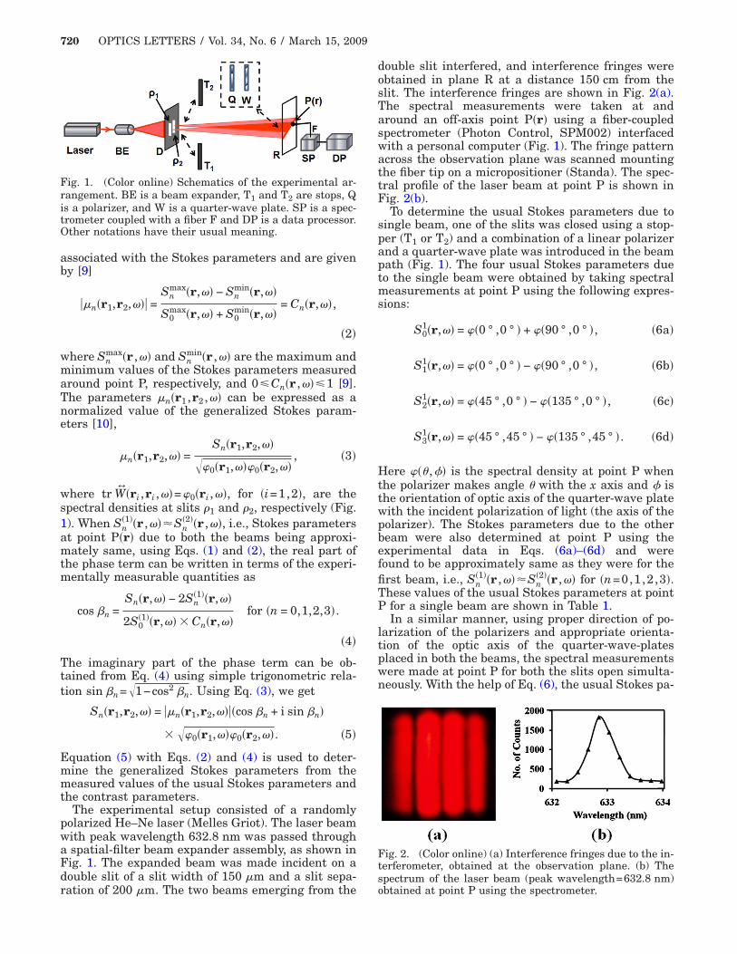
Fig. 1. (Color online) Schematics of the experimental ar-rangement. BE is a beam expander, T1 and T2 are stops, Qis a polarizer, and W is a quarter-wave plate. SP is a spec-trometer coupled with a fiber F and DP is a data processor.Other notations have their usual meaning.
ration of 200 �m. The two beams emerging from the
double slit interfered, and interference fringes wereobtained in plane R at a distance 150 cm from theslit. The interference fringes are shown in Fig. 2(a).The spectral measurements were taken at andaround an off-axis point P�r� using a fiber-coupledspectrometer (Photon Control, SPM002) interfacedwith a personal computer (Fig. 1). The fringe patternacross the observation plane was scanned mountingthe fiber tip on a micropositioner (Standa). The spec-tral profile of the laser beam at point P is shown inFig. 2(b).
To determine the usual Stokes parameters due tosingle beam, one of the slits was closed using a stop-per (T1 or T2) and a combination of a linear polarizerand a quarter-wave plate was introduced in the beampath (Fig. 1). The four usual Stokes parameters dueto the single beam were obtained by taking spectralmeasurements at point P using the following expres-sions:
S01�r,�� = ��0 ° ,0 ° � + ��90 ° ,0 ° �, �6a�
S11�r,�� = ��0 ° ,0 ° � − ��90 ° ,0 ° �, �6b�
S21�r,�� = ��45 ° ,0 ° � − ��135 ° ,0 ° �, �6c�
S31�r,�� = ��45 ° ,45 ° � − ��135 ° ,45 ° �. �6d�
Here ��� ,� is the spectral density at point P whenthe polarizer makes angle � with the x axis and isthe orientation of optic axis of the quarter-wave platewith the incident polarization of light (the axis of thepolarizer). The Stokes parameters due to the otherbeam were also determined at point P using theexperimental data in Eqs. (6a)–(6d) and werefound to be approximately same as they were for thefirst beam, i.e., Sn
�1��r ,���Sn�2��r ,�� for �n=0,1,2,3�.
These values of the usual Stokes parameters at pointP for a single beam are shown in Table 1.
In a similar manner, using proper direction of po-larization of the polarizers and appropriate orienta-tion of the optic axis of the quarter-wave-platesplaced in both the beams, the spectral measurementswere made at point P for both the slits open simulta-neously. With the help of Eq. (6), the usual Stokes pa-
Fig. 2. (Color online) (a) Interference fringes due to the in-terferometer, obtained at the observation plane. (b) Thespectrum of the laser beam (peak wavelength=632.8 nm)
obtained at point P using the spectrometer.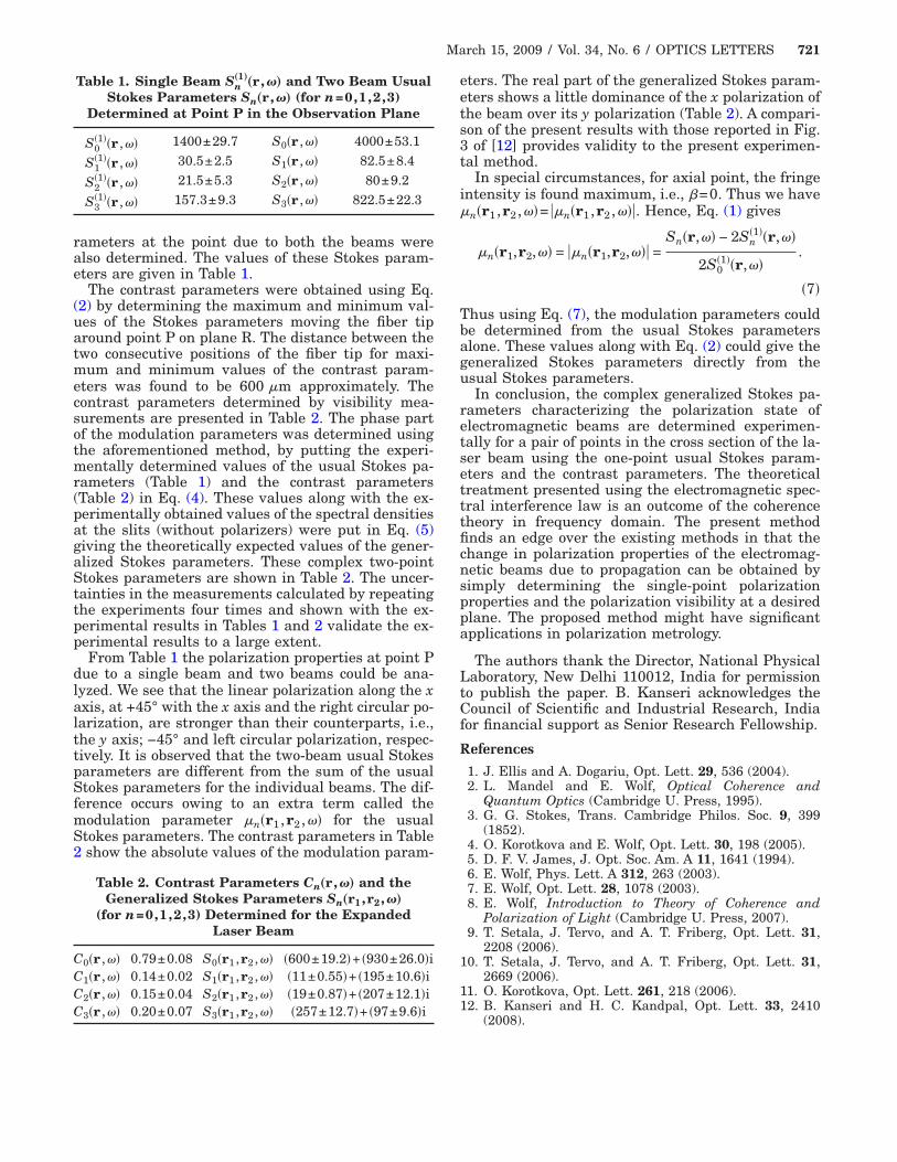
March 15, 2009 / Vol. 34, No. 6 / OPTICS LETTERS 721
rameters at the point due to both the beams werealso determined. The values of these Stokes param-eters are given in Table 1.
The contrast parameters were obtained using Eq.(2) by determining the maximum and minimum val-ues of the Stokes parameters moving the fiber tiparound point P on plane R. The distance between thetwo consecutive positions of the fiber tip for maxi-mum and minimum values of the contrast param-eters was found to be 600 �m approximately. Thecontrast parameters determined by visibility mea-surements are presented in Table 2. The phase partof the modulation parameters was determined usingthe aforementioned method, by putting the experi-mentally determined values of the usual Stokes pa-rameters (Table 1) and the contrast parameters(Table 2) in Eq. (4). These values along with the ex-perimentally obtained values of the spectral densitiesat the slits (without polarizers) were put in Eq. (5)giving the theoretically expected values of the gener-alized Stokes parameters. These complex two-pointStokes parameters are shown in Table 2. The uncer-tainties in the measurements calculated by repeatingthe experiments four times and shown with the ex-perimental results in Tables 1 and 2 validate the ex-perimental results to a large extent.
From Table 1 the polarization properties at point Pdue to a single beam and two beams could be ana-lyzed. We see that the linear polarization along the xaxis, at +45° with the x axis and the right circular po-larization, are stronger than their counterparts, i.e.,the y axis; −45° and left circular polarization, respec-tively. It is observed that the two-beam usual Stokesparameters are different from the sum of the usualStokes parameters for the individual beams. The dif-ference occurs owing to an extra term called themodulation parameter �n�r1 ,r2 ,�� for the usualStokes parameters. The contrast parameters in Table2 show the absolute values of the modulation param-
Table 1. Single Beam Sn„1…„r,�… and Two Beam Usual
Stokes Parameters Sn„r,�… (for n=0,1,2,3)Determined at Point P in the Observation Plane
S0�1��r ,�� 1400±29.7 S0�r ,�� 4000±53.1
S1�1��r ,�� 30.5±2.5 S1�r ,�� 82.5±8.4
S2�1��r ,�� 21.5±5.3 S2�r ,�� 80±9.2
S3�1��r ,�� 157.3±9.3 S3�r ,�� 822.5±22.3
Table 2. Contrast Parameters Cn„r,�… and theGeneralized Stokes Parameters Sn„r1,r2,�…
(for n=0,1,2,3) Determined for the ExpandedLaser Beam
C0�r ,�� 0.79±0.08 S0�r1 ,r2 ,�� �600±19.2�+ �930±26.0�iC1�r ,�� 0.14±0.02 S1�r1 ,r2 ,�� �11±0.55�+ �195±10.6�iC2�r ,�� 0.15±0.04 S2�r1 ,r2 ,�� �19±0.87�+ �207±12.1�iC3�r ,�� 0.20±0.07 S3�r1 ,r2 ,�� �257±12.7�+ �97±9.6�i
eters. The real part of the generalized Stokes param-eters shows a little dominance of the x polarization ofthe beam over its y polarization (Table 2). A compari-son of the present results with those reported in Fig.3 of [12] provides validity to the present experimen-tal method.
In special circumstances, for axial point, the fringeintensity is found maximum, i.e., �=0. Thus we have�n�r1 ,r2 ,��= ��n�r1 ,r2 ,���. Hence, Eq. (1) gives
�n�r1,r2,�� = ��n�r1,r2,��� =Sn�r,�� − 2Sn
�1��r,��
2S0�1��r,��
.
�7�
Thus using Eq. (7), the modulation parameters couldbe determined from the usual Stokes parametersalone. These values along with Eq. (2) could give thegeneralized Stokes parameters directly from theusual Stokes parameters.
In conclusion, the complex generalized Stokes pa-rameters characterizing the polarization state ofelectromagnetic beams are determined experimen-tally for a pair of points in the cross section of the la-ser beam using the one-point usual Stokes param-eters and the contrast parameters. The theoreticaltreatment presented using the electromagnetic spec-tral interference law is an outcome of the coherencetheory in frequency domain. The present methodfinds an edge over the existing methods in that thechange in polarization properties of the electromag-netic beams due to propagation can be obtained bysimply determining the single-point polarizationproperties and the polarization visibility at a desiredplane. The proposed method might have significantapplications in polarization metrology.
The authors thank the Director, National PhysicalLaboratory, New Delhi 110012, India for permissionto publish the paper. B. Kanseri acknowledges theCouncil of Scientific and Industrial Research, Indiafor financial support as Senior Research Fellowship.
References
1. J. Ellis and A. Dogariu, Opt. Lett. 29, 536 (2004).2. L. Mandel and E. Wolf, Optical Coherence and
Quantum Optics (Cambridge U. Press, 1995).3. G. G. Stokes, Trans. Cambridge Philos. Soc. 9, 399
(1852).4. O. Korotkova and E. Wolf, Opt. Lett. 30, 198 (2005).5. D. F. V. James, J. Opt. Soc. Am. A 11, 1641 (1994).6. E. Wolf, Phys. Lett. A 312, 263 (2003).7. E. Wolf, Opt. Lett. 28, 1078 (2003).8. E. Wolf, Introduction to Theory of Coherence and
Polarization of Light (Cambridge U. Press, 2007).9. T. Setala, J. Tervo, and A. T. Friberg, Opt. Lett. 31,
2208 (2006).10. T. Setala, J. Tervo, and A. T. Friberg, Opt. Lett. 31,
2669 (2006).11. O. Korotkova, Opt. Lett. 261, 218 (2006).12. B. Kanseri and H. C. Kandpal, Opt. Lett. 33, 2410
(2008).