Embed Size (px)
Citation preview
Direct Control Methods for Matrix Converter andInduction Machine
J. Boll, F.W. FuchsInstitute for Power Electronics and Electrical Drives
Christian-Albrechts-University of Kiel, [email protected], [email protected]
Abstract—Several methods for direct control of matrixconverter and induction machine have been developed inrecent years. To give an overview and comparison some ofthem are selected and presented in this paper. Included arethe basics of Direct Torque Control, Direct Current Controland Sliding Mode Control of matrix converters.
I. INTRODUCTION
In recent years many research results on controlmethods for matrix converters have been published. In thefield of matrix converter control research work has beendone since many years [1]. Commutation and protectionissues have been investigated to a high status [2-4]. Earlypapers concentrated on converter open loop control [1],[5]. Another topic of great interest is the closed loopcontrol of a drive system consisting of matrix converterand induction machine. Slip control and field orientedcontrol are the basic methods applied for closed loopcontrol [4]. Another quite new interesting topic is theapplication of modern direct control methods to thesystem with matrix converter and induction machine.
In this paper, the most important direct control methodsfor matrix converter and induction machine are presentedto give an overview and comparison. These methods areDirect Torque Control (DTC), Direct Current Control(DCC) and sliding mode control.
After a short introduction to matrix converter principlesand switching constraints in section II an overview ofpossible switch configurations and their resulting spacevectors will be given. In section III the basic ideas of thethree control methods mentioned above will be outlined,starting with Direct Torque Control and Sliding ModeControl, as these methods use the same switchconfigurations of the matrix converter, and ending withDirect Current Control. In section IV similarities anddifferences of the control methods are mentioned and insection V follows a conclusion.
II. MATRIX CONVERTER PRINCIPLES
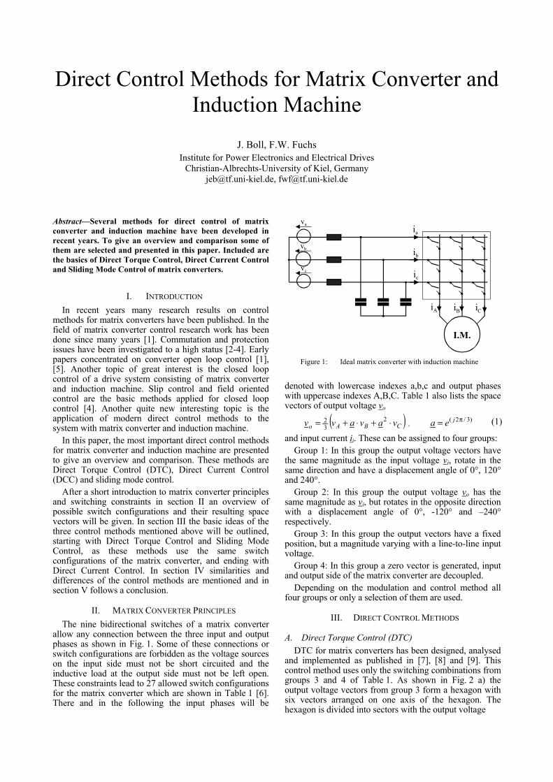
The nine bidirectional switches of a matrix converterallow any connection between the three input and outputphases as shown in Fig. 1. Some of these connections orswitch configurations are forbidden as the voltage sourceson the input side must not be short circuited and theinductive load at the output side must not be left open.These constraints lead to 27 allowed switch configurationsfor the matrix converter which are shown in Table 1 [6].There and in the following the input phases will be
denoted with lowercase indexes a,b,c and output phaseswith uppercase indexes A,B,C. Table 1 also lists the spacevectors of output voltage vo
( )CBAo vavavv ⋅+⋅+= 232 ,
)3/2( π= jea (1)
and input current ii. These can be assigned to four groups:Group 1: In this group the output voltage vectors have
the same magnitude as the input voltage vi, rotate in thesame direction and have a displacement angle of 0°, 120°and 240°.
Group 2: In this group the output voltage vo has thesame magnitude as vi, but rotates in the opposite directionwith a displacement angle of 0°, -120° and –240°respectively.
Group 3: In this group the output vectors have a fixedposition, but a magnitude varying with a line-to-line inputvoltage.
Group 4: In this group a zero vector is generated, inputand output side of the matrix converter are decoupled.
Depending on the modulation and control method allfour groups or only a selection of them are used.
III. DIRECT CONTROL METHODS
A. Direct Torque Control (DTC)DTC for matrix converters has been designed, analysed
and implemented as published in [7], [8] and [9]. Thiscontrol method uses only the switching combinations fromgroups 3 and 4 of Table 1. As shown in Fig. 2 a) theoutput voltage vectors from group 3 form a hexagon withsix vectors arranged on one axis of the hexagon. Thehexagon is divided into sectors with the output voltage
I.M.
va
vb
vc
iA
ia
ic
ib
iB iC
Figure 1: Ideal matrix converter with induction machine
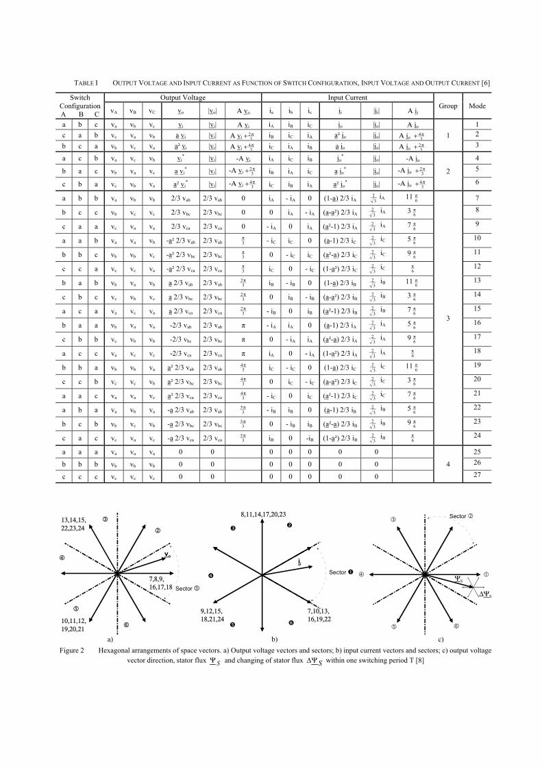
TABLE I OUTPUT VOLTAGE AND INPUT CURRENT AS FUNCTION OF SWITCH CONFIGURATION, INPUT VOLTAGE AND OUTPUT CURRENT [6]
Output Voltage Input CurrentSwitchConfigurationA B C vA vB vC vo |vo| Α vo ia ib ic ii |ii| Α ii
Group Mode
a b c va vb vc vi |vi| Α vi iA iB iC io |io| Α io 1c a b vc va vb a vi |vi| Α vi 3
2π+ iB iC iA a² io |io| Α io 34π+ 2
b c a vb vc va a² vi |vi| Α vi 34π+ iC iA iB a io |io| Α io 3
2π+
13
a c b va vc vb vi* |vi| -Α vi iA iC iB io
* |io| -Α io 4
b a c vb va vc a vi* |vi| -Α vi 3
2π+ iB iA iC a io* |io| -Α io 3
2π+ 5
c b a vc vb va a² vi* |vi| -Α vi 3
4π+ iC iB iA a² io* |io| -Α io 3
4π+
26
a b b va vb vb 2/3 vab 2/3 vab 0 iA - iA 0 (1-a) 2/3 iA 32 iA 11 6
π 7
b c c vb vc vc 2/3 vbc 2/3 vbc 0 0 iA - iA (a-a²) 2/3 iA 32 iA 3 6
π 8
c a a vc va va 2/3 vca 2/3 vca 0 - iA 0 iA (a²-1) 2/3 iA 32 iA 7 6
π 9
a a b va va vb -a² 2/3 vab 2/3 vab 3π - iC iC 0 (a-1) 2/3 iC 3
2 iC 5 6π 10
b b c vb vb vc -a² 2/3 vbc 2/3 vbc 3π 0 - iC iC (a²-a) 2/3 iC 3
2 iC 9 6π 11
c c a vc vc va -a² 2/3 vca 2/3 vca 3π iC 0 - iC (1-a²) 2/3 iC 3
2 iC 6π 12
b a b vb va vb a 2/3 vab 2/3 vab 32π iB - iB 0 (1-a) 2/3 iB 3
2 iB 11 6π 13
c b c vc vb vc a 2/3 vbc 2/3 vbc 32π 0 iB - iB (a-a²) 2/3 iB 3
2 iB 3 6π 14
a c a va vc va a 2/3 vca 2/3 vca 32π - iB 0 iB (a²-1) 2/3 iB 3
2 iB 7 6π 15
b a a vb va va -2/3 vab 2/3 vab π - iA iA 0 (a-1) 2/3 iA 32 iA 5 6
π 16
c b b vc vb vb -2/3 vbc 2/3 vbc π 0 - iA iA (a²-a) 2/3 iA 32 iA 9 6
π 17
a c c va vc vc -2/3 vca 2/3 vca π iA 0 - iA (1-a²) 2/3 iA 32 iA 6
π 18
b b a vb vb va a² 2/3 vab 2/3 vab 34π iC - iC 0 (1-a) 2/3 iC 3
2 iC 11 6π 19
c c b vc vc vb a² 2/3 vbc 2/3 vbc 34π 0 iC - iC (a-a²) 2/3 iC 3
2 iC 3 6π 20
a a c va va vc a² 2/3 vca 2/3 vca 34π - iC 0 iC (a²-1) 2/3 iC 3
2 iC 7 6π 21
a b a va vb va -a 2/3 vab 2/3 vab 35π - iB iB 0 (a-1) 2/3 iB 3
2 iB 5 6π 22
b c b vb vc vb -a 2/3 vbc 2/3 vbc 35π 0 - iB iB (a²-a) 2/3 iB 3
2 iB 9 6π 23
c a c vc va vc -a 2/3 vca 2/3 vca 35π iB 0 -iB (1-a²) 2/3 iB 3
2 iB 6π
3
24
a a a va va va 0 0 0 0 0 0 0 25
b b b vb vb vb 0 0 0 0 0 0 0 26
c c c vc vc vc 0 0 0 0 0 0 0
427
Sector
Sector 7,8,9,16,17,18
10,11,12,19,20,21
13,14,15,22,23,24
vo
Sector
ii
7,10,13,16,19,22
9,12,15,18,21,24
8,11,14,17,20,23
ΨS
∆ΨS
a) b) c)Figure 2 Hexagonal arrangements of space vectors. a) Output voltage vectors and sectors; b) input current vectors and sectors; c) output voltage
vector direction, stator flux SΨ and changing of stator flux SΨ∆ within one switching period T [8]
vectors situated in the middle of each sector. A similarconfiguration exists for the input current vectors(Fig. 2b)), here the current vectors are forming the sectorboundaries.
The principle of DTC is to keep stator flux and torquewithin certain limits by compairing their actual valueswith the reference values via two hysteresis controllers[10]. Fig. 2c) shows a stator flux vector SΨ within theoutput voltage hexagon. The small hexagon at the tip ofthis vector indicates the directions SΨ∆ , in which thestator flux vector may be changed within one switchingperiod T by application of one of the voltage vectorswhich have different directions.
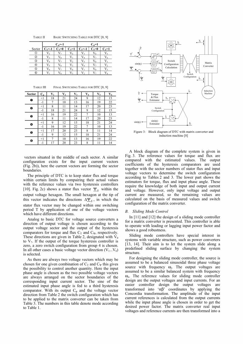
Analog to basic DTC for voltage source converters adirection of output voltage is chosen according to theoutput voltage sector and the output of the hysteresiscomparators for torque and flux CT and CΨ, respectively.These directions are given in Table 2, designated with V0to V7. If the output of the torque hysteresis controller iszero, a zero switch configuration from group 4 is chosen.In all other cases a basic voltage vector direction (V1...V6)is selected.
As there are always two voltage vectors which may bechosen for one given combination of CT and CΨ this givesthe possibility to control another quantity. Here the inputphase angle is chosen as the two possible voltage vectorsare always arranged on the sector boundaries of thecorresponding input current sector. The sine of theestimated input phase angle is fed to a third hysteresiscomparator. With its output Cϕ and the voltage vectordirection from Table 2 the switch configuration which hasto be applied to the matrix converter can be taken fromTable 3. The numbers in this table denote mode accordingto Table 1.
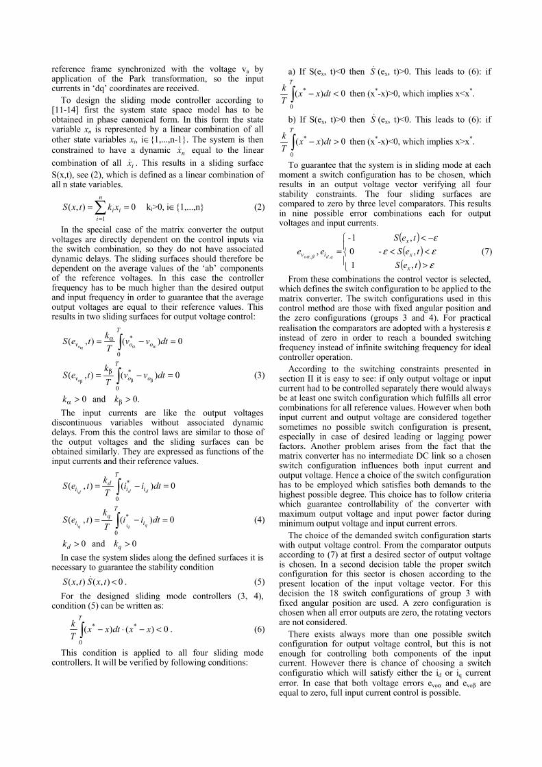
A block diagram of the complete system is given inFig. 3. The reference values for torque and flux arecompared with the estimated values. The outputcoefficients of the hysteresis comparators are usedtogether with the sector numbers of stator flux and inputvoltage vectors to determine the switch configurationaccording to Tables 2 and 3. The lower part shows theestimators for torque, flux and input phase angle. Theserequire the knowledge of both input and output currentand voltage. However, only input voltage and outputcurrent are measured, so the remaining values arecalculated on the basis of measured values and switchconfiguration of the matrix converter.
B. Sliding Mode ControlIn [11] and [12] the design of a sliding mode controller
for a matrix converter is presented. This controller is ableto operate with leading or lagging input power factor andshows a good robustness.
Sliding mode controllers have special interest insystems with variable structure, such as power converters[13, 14]. Their aim is to let the system slide along apredefined sliding surface by changing the systemstructure.
For designing the sliding mode controller, the source isassumed to be a balanced sinusoidal three phase voltagesource with frequency ωι. The output voltages areassumed to be a similar balanced system with frequencyωo. The reference values for sliding mode controllerdesign are the output voltages and input currents. For aneasier controller design the output voltages aretransformed into ‘αβ’ coordinates by applying theConcordia transformation. The amplitude of the inputcurrent references is calculated from the output currentswhile the input phase angle is chosen in order to get thedesired power factor. The matrix converter real inputvoltages and reference currents are then transformed into a
15
43
6
2
15
43
6
2
+
+
Switch ConfigurationCalculation
Matrix Converter
InductionMachine
{
{
Ψ^S
^T
T*
ΨS
∗
CT
Cϕ
CΨ
sin(ϕi)
vivi
io
Switch Configuration
oi
oi
Torque & Flux
Estimator
sin(ϕi) Estimator
sin(ϕi)
^Tio
ii
vi
vo
Switch Configuration
Ψ^S
Ψ^S
Figure 3: Block diagram of DTC with matrix converter andinduction machine [8]
TABLE II BASIC SWITCHING TABLE FOR DTC [8, 9]
Cψ=-1 Cψ=1Sector CT=-1 CT=0 CT=1 CT=-1 CT=0 CT=1
V2 V7 V6 V3 V0 V5
V3 V0 V1 V4 V7 V6
V4 V7 V2 V5 V0 V1
V5 V0 V3 V6 V7 V2
V6 V7 V4 V1 V0 V3
V1 V0 V5 V2 V7 V4
TABLE III FINAL SWITCHING TABLE FOR DTC [8, 9]
Sector Cϕ V1 V2 V3 V4 V5 V6
+1 18 21 24 9 12 15-1 7 10 13 16 19 22+1 8 11 14 17 20 23-1 18 21 24 9 12 15+1 16 19 22 7 10 13-1 8 11 14 17 20 23+1 9 12 15 18 21 24-1 16 19 22 7 10 13+1 17 20 23 8 11 14-1 9 12 15 18 21 24+1 7 10 13 16 19 22-1 17 20 23 8 11 14
reference frame synchronized with the voltage va byapplication of the Park transformation, so the inputcurrents in ‘dq’ coordinates are received.
To design the sliding mode controller according to[11-14] first the system state space model has to beobtained in phase canonical form. In this form the statevariable xn is represented by a linear combination of allother state variables xi, i∈{1,...,n-1}. The system is thenconstrained to have a dynamic nx& equal to the linearcombination of all ix& . This results in a sliding surfaceS(x,t), see (2), which is defined as a linear combination ofall n state variables.
∑=
==n
iii xktxS
1
0),( ki>0, i∈{1,...,n} (2)
In the special case of the matrix converter the outputvoltages are directly dependent on the control inputs viathe switch combination, so they do not have associateddynamic delays. The sliding surfaces should therefore bedependent on the average values of the ‘ab’ componentsof the reference voltages. In this case the controllerfrequency has to be much higher than the desired outputand input frequency in order to guarantee that the averageoutput voltages are equal to their reference values. Thisresults in two sliding surfaces for output voltage control:
.0 and 0
0)(),(
0)(),(
0
*
0
*
>>
=−=
=−=
βα
β
α
βββ
ααα
∫
∫
kk
dtvvTk
teS
dtvvTkteS
o
T
ov
o
T
ov
o
o
(3)
The input currents are like the output voltagesdiscontinuous variables without associated dynamicdelays. From this the control laws are similar to those ofthe output voltages and the sliding surfaces can beobtained similarly. They are expressed as functions of theinput currents and their reference values.
0 and 0
0)(),(
0)(),(
0
*
0
*
>>
=−=
=−=
∫
∫
qd
i
Tq
i
i
T
id
i
kk
dtiiTk
teS
dtiiTkteS
qqiqi
dddi
(4)
In case the system slides along the defined surfaces it isnecessary to guarantee the stability condition
0 ),( ),( <txStxS & . (5)For the designed sliding mode controllers (3, 4),
condition (5) can be written as:
0)()( *
0
* <−⋅−∫ xxdtxxTk
T
. (6)
This condition is applied to all four sliding modecontrollers. It will be verified by following conditions:
a) If S(ex, t)<0 then S& (ex, t)>0. This leads to (6): if
0)(0
* <−∫T
dtxxTk then (x*-x)>0, which implies x<x*.
b) If S(ex, t)>0 then S& (ex, t)<0. This leads to (6): if
0)(0
* >−∫T
dtxxTk then (x*-x)<0, which implies x>x*.
To guarantee that the system is in sliding mode at eachmoment a switch configuration has to be chosen, whichresults in an output voltage vector verifying all fourstability constraints. The four sliding surfaces arecompared to zero by three level comparators. This resultsin nine possible error combinations each for outputvoltages and input currents.
( )( )
( )
><<−<
=εεεε
βα
teSteS
teSee
x
x
x
iv qdo
, 1,- 0
, 1- ,
,,(7)
From these combinations the control vector is selected,which defines the switch configuration to be applied to thematrix converter. The switch configurations used in thiscontrol method are those with fixed angular position andthe zero configurations (groups 3 and 4). For practicalrealisation the comparators are adopted with a hysteresis εinstead of zero in order to reach a bounded switchingfrequency instead of infinite switching frequency for idealcontroller operation.
According to the switching constraints presented insection II it is easy to see: if only output voltage or inputcurrent had to be controlled separately there would alwaysbe at least one switch configuration which fulfills all errorcombinations for all reference values. However when bothinput current and output voltage are considered togethersometimes no possible switch configuration is present,especially in case of desired leading or lagging powerfactors. Another problem arises from the fact that thematrix converter has no intermediate DC link so a chosenswitch configuration influences both input current andoutput voltage. Hence a choice of the switch configurationhas to be employed which satisfies both demands to thehighest possible degree. This choice has to follow criteriawhich guarantee controllability of the converter withmaximum output voltage and input power factor duringminimum output voltage and input current errors.
The choice of the demanded switch configuration startswith output voltage control. From the comparator outputsaccording to (7) at first a desired sector of output voltageis chosen. In a second decision table the proper switchconfiguration for this sector is chosen according to thepresent location of the input voltage vector. For thisdecision the 18 switch configurations of group 3 withfixed angular position are used. A zero configuration ischosen when all error outputs are zero, the rotating vectorsare not considered.
There exists always more than one possible switchconfiguration for output voltage control, but this is notenough for controlling both components of the inputcurrent. However there is chance of choosing a switchconfiguratio which will satisfy either the id or iq currenterror. In case that both voltage errors evoα and evoβ areequal to zero, full input current control is possible.
For input current control the chosen switchconfigurations must cause minimum output voltage errorin order to minimise output voltage ripple. The basic ideais to maximize the time of evoα and evoβ equal to zerobecause this maximizes the input current control range.This leads to large decision tables depending on the fourerror variables and the sections of input voltage and outputcurrent. These tables are omitted here and can be found in[11].
C. Direct Current Control (DCC)In [15] and [6] a DCC method for matrix converters is
presented. It is based on the analysis of the matrixconverter’s transfer characteristics. By applying aswitching state to the matrix converter a certain voltagespace vector vo is generated at the output terminals andvice versa an input current ii. In a first step the control ofthe output current io is examined.
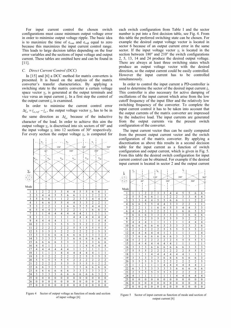
In order to minimise the current control errororefoo iii −=∆ , , the output voltage vector vo has to be in
the same direction as oi∆ because of the inductivecharacter of the load. In order to achieve this aim theoutput voltage vo is discretised into six sectors of 60° andthe input voltage vi into 12 sections of 30° respectively.For every section the output voltage vo is computed for
each switch configuration from Table I and the sectornumber is put into a first decision table, see Fig. 4. Fromthis table the preferred switching state can be chosen. Forexample the desired output voltage vector is located insector 6 because of an output current error in the samesector. If the input voltage vector vi is located in thesection between 180° and 210° the switch configurations2, 5, 13, 14 and 24 produce the desired output voltage.There are always at least three switching states whichproduce an output voltage vector with the desireddirection, so the output current could be easily controlled.However the input current has to be controlledsimultaneously.
In order to control the input current a PD-controller isused to determine the sector of the desired input current ii.This controller is also necessary for active damping ofoscillations of the input current which arise from the lowcutoff frequency of the input filter and the relatively lowswitching frequency of the converter. To complete theinput current control it has to be taken into account thatthe output currents of the matrix converter are impressedby the inductive load. The input currents are generatedfrom the output currents via the present switchconfiguration of the converter.
The input current vector thus can be easily computedfrom the present output current vector and the switchconfiguration of the matrix converter. By applying adiscretisation as above this results in a second decisiontable for the input current as a function of switchconfiguration and output current, which is given in Fig. 5.From this table the desired switch configuration for inputcurrent control can be obtained. For example if the desiredinput current is located in sector 2 and the output current
1 1 2 2 3 3 4 4 5 5 6 6 12 3 4 4 5 5 6 6 1 1 2 2 33 5 6 6 1 1 2 2 3 3 4 4 54 1 6 6 5 5 4 4 3 3 2 2 15 3 2 2 1 1 6 6 5 5 4 4 36 5 4 4 3 3 2 2 1 1 6 6 57 1 1 4 4 4 4 4 4 1 1 1 18 1 1 1 1 1 1 4 4 4 4 4 49 4 4 4 4 1 1 1 1 1 1 4 4
10 2 2 5 5 5 5 5 5 2 2 2 211 2 2 2 2 2 2 5 5 5 5 5 512 5 5 5 5 2 2 2 2 2 2 5 513 3 3 6 6 6 6 6 6 3 3 3 314 3 3 3 3 3 3 6 6 6 6 6 615 6 6 6 6 3 3 3 3 3 3 6 616 4 4 1 1 1 1 1 1 4 4 4 417 4 4 4 4 4 4 1 1 1 1 1 118 1 1 1 1 4 4 4 4 4 4 1 119 5 5 2 2 2 2 2 2 5 5 5 520 5 5 5 5 5 5 2 2 2 2 2 221 2 2 2 2 5 5 5 5 5 5 2 222 6 6 3 3 3 3 3 3 6 6 6 623 6 6 6 6 6 6 3 3 3 3 3 324 3 3 3 3 6 6 6 6 6 6 3 325 0 0 0 0 0 0 0 0 0 0 0 026 0 0 0 0 0 0 0 0 0 0 0 027 0 0 0 0 0 0 0 0 0 0 0 0
123
45 6
60°
Mode
va
120°
180°
240°
300°
360°
vb vc
vac vca vabvbavbc vcb
vo
Figure 4 Sector of output voltage as function of mode and sectionof input voltage [6]
1 1 1 2 2 3 3 4 4 5 5 6 62 5 5 6 6 1 1 2 2 3 3 4 43 3 3 4 4 5 5 6 6 1 1 2 24 6 6 5 5 4 4 3 3 2 2 1 15 2 2 1 1 6 6 5 5 4 4 3 36 4 4 3 3 2 2 1 1 6 6 5 57 6 6 6 3 3 3 3 3 3 6 6 68 2 2 2 5 5 5 5 5 5 2 2 29 4 4 4 1 1 1 1 1 1 4 4 4
10 6 6 6 6 6 3 3 3 3 3 3 611 2 2 2 2 2 5 5 5 5 5 5 212 4 4 4 4 4 1 1 1 1 1 1 413 3 6 6 6 6 6 6 3 3 3 3 314 5 2 2 2 2 2 2 5 5 5 5 515 1 4 4 4 4 4 4 1 1 1 1 116 3 3 3 6 6 6 6 6 6 3 3 317 5 5 5 2 2 2 2 2 2 5 5 518 1 1 1 4 4 4 4 4 4 1 1 119 3 3 3 3 3 6 6 6 6 6 6 320 5 5 5 5 5 2 2 2 2 2 2 521 1 1 1 1 1 4 4 4 4 4 4 122 6 3 3 3 3 3 3 6 6 6 6 623 2 5 5 5 5 5 5 2 2 2 2 224 4 1 1 1 1 1 1 4 4 4 4 425 0 0 0 0 0 0 0 0 0 0 0 026 0 0 0 0 0 0 0 0 0 0 0 027 0 0 0 0 0 0 0 0 0 0 0 0
60°
120°
180° 300°
240° 360°
iA iBiC
Mode
1234 5 6
ii
Figure 5 Sector of input current as function of mode and section ofoutput current [6]

vector is in the section between 120° and 150°, switchconfigurations 6, 11, 14 and 17 are suitable. If at the sametime the situation for the output current controller is as inthe example above, only mode 14 satisfies both controllerssimultaneously.
This results in two direct controllers for both outputcurrent io and input current ii. As there is not always aswitch configuration which satisfies both controller’sdemands, a third decision mechanism is applied. The flowdiagram of this mechanism is shown in Fig. 6: If bothcontrol errors are small, a zero vector (group 4) isselected. If a switch configuration exists which satisfiesboth controllers simultaneously, this configuration ischosen. In all other cases the weighted errors arecompared to each other and the decision table for thecontroller with the larger error is taken into account.Dependent on the magnitude of the error the switchconfiguration producing the lowest, medium or largestcurrent amplitude is chosen.
In Fig. 7 a block diagram of the control is given. Itshows the PD-controller at the mains side, whichdetermines the desired input current sector and amplitude.The sector of the input voltage vector is determined by aPLL. The output currents are measured and their spacevector is determined. From the tables in Fig. 4 and 5 thedesired switch configurations are obtained. From these thefinal switch configuration is determined by Fig. 6, whichis then applied to the converter. A more detaileddescription of the whole control scheme is given in [15].
IV. COMPARISON
The three direct control methods presented in this papershow various differences as well as similiarities. So bothDTC and sliding mode control use the same switchconfigurations of groups 3 and 4 (vectors with fixedangular position and zero vectors) while DCC uses therotating vectors of groups 1 and 2 additionally.Implementations of all three controller types show goodsteady state an dynamic behaviour. The common mainproblem is the time consuming process of calculation anddecision of the demanded switch configuration. This leadsto a high demand for cpu power or restrictsimplementations to a rather low switching frequency.
The higher number of usable voltage vectors with DTCfor matrix converters in comparison to voltage sourceconverters allows to control a third value next to torqueand flux. In this case the additional control of the inputpower factor has been chosen. In addition as presented in[8] the input current quality may be improved by usingboth possible switch configurations for input power factorcontrol during one sample period, thus including a kind ofPWM in DTC.
The presented sliding mode controllers for matrixconverters have been tested in their realisation withoperation under a wide range of input phase angles. At astep command in input phase angle from –70 to 70degrees they show a good steady state and dynamicbehaviour. The step response shows a fast reaction to thenew demands without remarkable overcurrents or voltagedistortions.
V. CONCLUSION
Modern direct control methods for matrix convertersare presented. The basic ideas of DTC, sliding modecontrol and DCC for matrix converter and inductionmachine are outlined as they can be found in literature. Allof these methods have been both simulated and realised inlab prototypes by the various authors. Differences andsimilarities of the selected direct control methods arepointed out.
REFERENCES
[1] A. Alesina, M.G.B. Venturini, “Analysis and Design of Optimum-Amplitude Nine-Switch Direct AC-AC Converters”, IEEE Trans.on Power Electron., vol. 4, no. 1, pp. 101-12 January 1989.
[2] L. Empringham, P. Wheeler, J. Clare, “Bi-Directional SwitchCommutation for Matrix Converters”, Proc. of EPE’99, Lausanne,Switzerland, CD-Rom paper 409.
[3] P. Nielsen, F. Blaabjerg, J.K. Pedersen, “New Protection Issues ofa matrix Converter: Design Considerations for Adjustable SpeedDrives”, IEEE Trans. on Ind. Appl., vol. 35, no. 5, pp. 1150-1161,September 1999.
[4] J. Mahlein, “Neue Verfahren für die Steuerung und den Schutz desMatrixumrichters”, Ph.D. dissertation in German, UniversityKarlsruhe, Germany 2002.
[5] L. Huber, D. Borojevič, “Space Vector Modulated Three-Phase toThree-Phase Matrix Converter with Input Power FactorCorrection”, IEEE Trans. on Ind. Applic., vol. 31, no. 6, pp. 1234-46, November 1995.
Mai
ns
Filter
Converter
xlow pass
filter
P K
xPLL
P-D-controller
Modeselection
Ii*
Ii*
Ii*
Ii
Vi I.M.
x
Io*
Io
Vi
Figure 7 Block diagram of DCC system (according to [6])
Start controller
End of controller
medium error
medium error
low error
low error
take a zero vector
use this mode
Is the line-side or the load-side controlerror out of a tolerable margin?
Is there a mode which satisfies both controllers simultaneously (Fig. 4&5)?
Is the weighted line-side control error larger than the load-side error?
use
grou
p-3-
mod
epr
oduc
ing
load
side
am
plitu
dela
rges
t
med
ium
low
est
use
grou
p-3-
mod
e pr
oduc
ing
load
side
am
plitu
dela
rges
t
med
ium
low
est
line-side preferred load-side preferred
y
y
y
y
y
y
y
n n
nn
n
n
n
Figure 6 Flow diagram of DCC mode selection [6]

[6] P. Mutschler and M. Marcks, “A Direct Control Method forMatrix Converters”, IEEE Trans. Ind. Electron., vol. 49, pp. 362-369, April 2002.
[7] D. Casadei, G. Grandi, G. Serra and A. Tani, “The Use of MatrixConverters in Direct Torque Control of Induction Machines,”Proc. of IECON’98, Aachen, Germany, pp.744-749.
[8] D. Casadei, M. Matteini, G. Serra, A. Tani and F. Blaabjerg,“Direct Torque Control using Matrix Converters: Improvement ofthe Input Line Current Quality,” Proc. of EPE’01, Graz, Austria,CD-ROM paper.
[9] D. Casadei, G. Serra and A. Tani, “The Use of Matrix Convertersin Direct Torque Control of Induction Machines,” IEEE Trans.Ind. Electron., vol. 48, pp. 1057-1064, December 2001.
[10] M. Depenbrok, “Direct Self-Control (DSC) of Inverter-FedInduction Machine”, IEEE Trans. on Power Electron., vol. 3,no. 4, pp. 420-29, October 1988.
[11] S. Ferreira Pinto, J. Fernando Silva,”Sliding Mode Control ofMatrix Converters with Lead-Lag Power Factor”, Proc. ofEPE’01, Graz, Austria, CD-ROM paper.
[12] S. Ferreira Pinto, J. Fernando Silva:, “Direct Control Method forMatrix Converters with Input Power Factor Correction”, Proc. ofPESC’04, Aachen, Germany, pp. 2366-2372, 2004.
[13] W. Gao, J. Hung “Variable Structure Control of NonlinearSystems: a New Approach”, IEEE Trans. Ind. Electron., vol. 40,no. 1, pp.45-54, January 1993.
[14] V. Utkin, “Sliding Mode Design Principles and Applications toElectric Drives”, IEEE Trans. Ind. Electron., vol.40, no. 1, pp.23-36, January 1993.
[15] M. Marcks, “Direkte Regelung eines Matrixumrichters sowie dieMöglichkeit zum stromlosen Schalten”, Ph.D. dissertation inGerman, Univ. Technol. Darmstadt, Germany 1998.