Embed Size (px)
Citation preview

Leonardo Technologies, Inc. (LTI), March 23, 2009
Direct Coal Liquefaction OverviewPresented to NETLJohn Winslow and Ed SchmetzLeonardo Technologies, Inc.

2
Direct Liquefaction Presentation OutlineDirect Liquefaction Presentation Outline
• What is Direct Coal Liquefaction (DCL)? And How does it Differ from Indirect Liquefaction (ICL)?
• History of U.S/Foreign DCL Processes• Comparison of Results from DOE DCL Technology Support
– EDS; H-Coal; HRI• Overall Findings• DOE Previous DCL Designs and Potential Vendors• Environmental Considerations/Fuel Specifications• Current DCL Technology Developments
– Shenhua; Accelergy• LTI Thoughts and Comments/Recommendations
– Analysis– R&D
Details are found in supporting presentations

3
Direct Liquefaction Presentation SummaryDirect Liquefaction Presentation Summary•DOE support for direct coal liquefaction occurred mainly over the period 1976-2000.
• About 90% of total DOE funding of $3.6 billion was spent for the large scale demo program (1976-82) referred to as Phase I, which showed the overall engineering feasibility and applicability of direct liquefaction to a wide range of coals.
• Processes demonstrated included SRC (both I and II), EDS and H-Coal. Supporting research paved the way for process improvements
•Three main components: •Phase I to accelerate the technology as a short-term response to ‘70s energy crisis;
•Fundamental research to develop improvements and identify alternatives;
•Phase II bench/pilot-scale program to overcome technical and economic deficiencies in Phase I (Lummus, HTI and Wilsonville facility)

4
Direct Liquefaction Presentation Summary (2)Direct Liquefaction Presentation Summary (2)• Accomplishments of Phase II
•Higher distillate yields…naphtha, mid-distillate and gas oil (~ 70% vs. ~50%)
•Higher quality liquids…no resid and metals and low heteroatom content; naphtha can be processed in conventional refineries
•Higher hydrogen content and lower product boiling point end point alleviated carcinogenity concerns
•Applicability to low rank coals and mixed feedstocks ..coprocessing with petroleum resides, heavy oils, waste plastics
•Valuable chemicals can be produced…cresylics, wax, BTX, argon, krypton; suggests possible advantage of direct liquefaction with IGCC
•Burke, etal concluded that radical departures from the DOE-supported direct liquefaction program are unlikely to result in substantially improved processes

5
Fuels H/C RatiosFuels H/C Ratios
• To make liquid fuels from coal - need to add hydrogen or reject carbon
• To make liquid fuels from natural gas - need to reject hydrogen or add carbon
• Adding hydrogen and rejecting carbon (or vice versa) may be equivalent:
CO + H2O ! CO2 + H2
Water Gas Shift (WGS) Reaction
4.0
Natural Gas
CTL
GTL
John Marano, April 2006, presentation to NETL

6
Direct Liquefaction Block Flow DiagramDirect Liquefaction Block Flow Diagram
CoalPreparation
CoalLiquefaction
Coal LiquidsHydrotraeating
HydrogenRecovery
GasPlant
Gasification
SulfurRecovery
LPG & Butanes
H2Naphtha (gasoline)
Distillate (diesel)
to refinery
H2
AcidGas
Solid/LiquidSeparation
Coal
Refuse
AshConc.
AirSeparation
O2 Air
N2
DonorSolventRecycle
Steam & PowerGeneration
Ammonia & Phenol
Recovery,WWT
Sulfur
H2
Purge
PlantFuel Gas
John Marano, April 2006, presentation to NETL

7
Direct Liquefaction DefinedDirect Liquefaction Defined
• Direct liquefaction processes add hydrogen to the hydrogen deficient organic structure of the coal, breaking it down only as far as is necessary to produce distillable liquids.
• Coal dissolution is accomplished under high temperature (~400 0C) and pressure (~1500-3000 psi) with hydrogen and a coal-derived solvent.
• The coal fragments are further hydrocracked to produce a synthetic crude oil.
• This synthetic crude must then undergo refinery upgrading and hydrotreating to produce acceptable transportation fuels.

8
Comparing Direct and Indirect LiquefactionComparing Direct and Indirect Liquefaction
• In Direct Liquefaction (DL) pressure, heat and catalyst are used to crack the coal to make liquids– theoretical efficiency can be high…roughly 70-75%– “sledge hammer” approach
• In Indirect Liquefaction (IL) coal is first gasified to form syngas. Syngas is then converted to liquids by means of a catalyst and Fischer Tropsch (FT) chemistry– Synthesis Gas or Syngas – mixture of CO, H2, CO2, H2O– theoretical efficiency is lower…roughly 60-65%– “engineered” approach
John Marano, April 2006, presentation to NETL

9
The Direct Conversion Process BasicsThe Direct Conversion Process Basics
! Process
" Dissolution
" Hydrocracking and hydrotreating
" Heat
" Pressure
" Catalyst
Coal FragmentsPreasphaltenes
Asphaltenes
Oils
Retrograde Reaction
Catalytic Hydrocracking
Transportation Fuels
Hydrotreating
Coal
High molecular weight
10
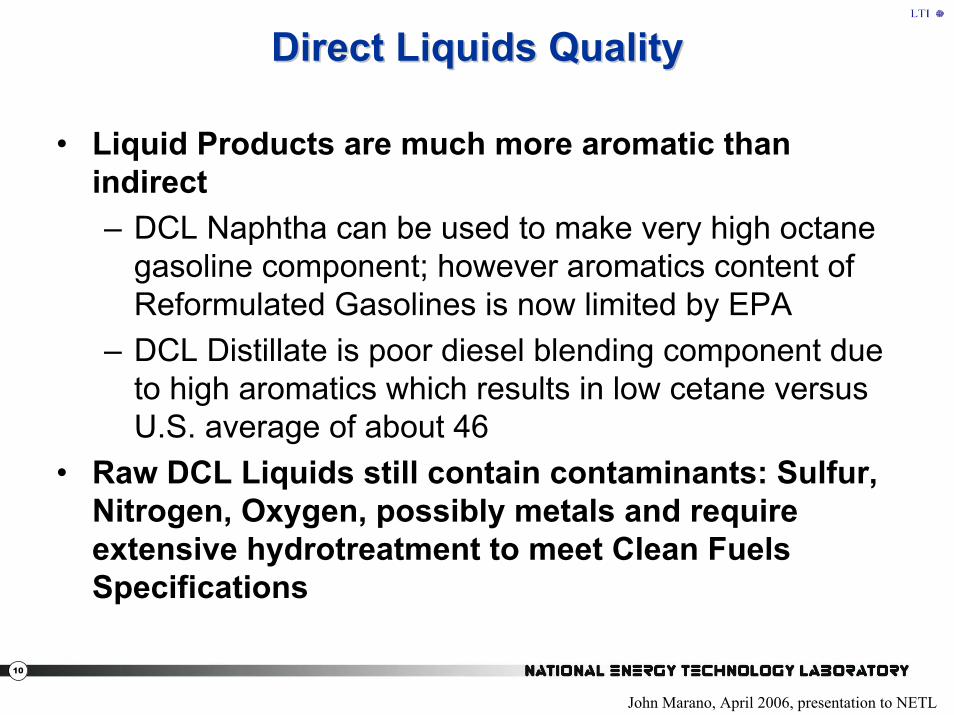
• Liquid Products are much more aromatic than indirect– DCL Naphtha can be used to make very high octane
gasoline component; however aromatics content of Reformulated Gasolines is now limited by EPA
– DCL Distillate is poor diesel blending component due to high aromatics which results in low cetane versus U.S. average of about 46
• Raw DCL Liquids still contain contaminants: Sulfur, Nitrogen, Oxygen, possibly metals and require extensive hydrotreatment to meet Clean Fuels Specifications
Direct Liquids QualityDirect Liquids Quality
John Marano, April 2006, presentation to NETL

11
Direct Liquefaction ProcessDirect Liquefaction Process
• A single-stage direct liquefaction process gives distillates via one primary reactor. Such processes may include an integrated on-line hydrotreating reactor, which is intended to upgrade the primary distillates without directly increasing the overall conversion.
• A two-stage direct liquefaction process is designed to give distillate products via two reactor stages in series. The primary function of the first stage is coal dissolution and is operated either without a catalyst or with only a low-activity disposable catalyst. The heavy coal liquids produced in this way are hydrotreated in the second stage in the presence of a high-activity catalyst to produce additional distillate.

12
Direct Liquefaction BenefitsDirect Liquefaction Benefits
• Direct liquefaction efficiency may be higher than indirect technology. One ton of a high volatile bituminous coal can be converted intoapproximately three barrels of high quality distillate syncrude for refinery upgrading and blending
• Direct Liquefaction provides high octane, low sulfur gasoline and a distillate that will require upgrading to make an acceptable diesel blending stock
• Development of direct liquefaction technology could lead to hybrid (direct/indirect) processes producing high quality gasoline and diesel
• The NCC, others suggest that direct liquefaction may have a better carbon footprint than indirect technology

13
Direct Liquefaction ChallengesDirect Liquefaction Challenges• Uncertainty in World Oil Prices • High Capital Costs • Investment Risk• Technical Challenges
– First technology (since 2nd World War) is being commercialized in the PRC (Shenhua) – need other first-of-kind large scale operation (with carbon management) to verify baselines and economics
– R&D activity should focus on remaining process issues such as further improvement in efficiency, product cost and quality, reliability of materials and components* and data needed to better define carbon life cycle
– The timelines for demonstration and development of direct liquefaction technology and carbon capture and storage must be integrated.
– Hybrid technology needs development including integrated demonstration
• Environmental Challenges – CO2 and criteria pollutants– Water use
• Concerns with increased coal use in U.S.
* The Shenhua commercial plant will provide new information on reliability and performance

14
U.S. Direct Liquefaction Process HistoryU.S. Direct Liquefaction Process HistoryYear
1945-1953
1962-Early 1980s
1963-1972
1970s-Early 1980s
1965-Early 1980s
Late 1960s-Early 1980sEarly 1980s-Late 1980s
1990-1995
ProcessBergius
– Louisiana, MOSolvent Refined Coal (SRC)
– Pott-BrocheConsol Synthetic Fuels (CSF)
– Two-Stage, CatalyticSRC-I and SRC II (Gulf Oil Fort Lewis)
– One-Stage, Non-catalyticH-Coal (Catlettsburg KY, HRI)
– One-Stage, CatalyticEXXON Donor Solvent (Baytown, TX)
Integrated Two-Stage Liquefaction (ITSL)– Lummus– Wilsonville (Southern Company)– HRI
Multi-Stage Slurry Phase Liquefaction HTI
Coal Capacity100 tons/day
50 tons/day
20 tons/day
50 tons/day
250 tons/day
250 tons/day
6 tons/day
3 tons/day Proof-of-concept
Consol Energy Inc. and Mitretek Systems, July 2001

15
NonNon--U.S. Direct Liquefaction ProcessesU.S. Direct Liquefaction Processes
Country
Germany
Japan
Facility
BOTTROP Plant– I.G. Farben Variant
Brown Coal Liquefaction Plant– ITSL Variant– Victoria, Australia
Capacity Tons/Day
200
50
Status
Shut Down
Shut Down (~1990)
Japan
U.K.
China
Nedol Plant– ITSL Variant– BIT. and SUBBIT. Coals
Point-of-AYR Plant– ITSL Variant
Inner Mongolia
150
2.5
7,000
Shut down (Late 1990s)
Shut Down (~1990)
Start-up 2008
Consol Energy Inc. and Mitretek Systems, July 2001

16
Comparison of Results for Comparison of Results for DOE Direct Liquefaction DOE Direct Liquefaction
ProgramProgram

17
DOE Sponsored ProgramsDOE Sponsored Programs19681968--19951995
• Phase I processes– SRC-II– Exxon Donor Solvent (EDS)– H-Coal
• Phase II process campaigns– Lummus Integrated Two-Stage Liquefaction (ITSL)– Wilsonville Two-Stage Liquefaction– HRI/HTI Catalytic Multi-Stage Liquefaction (CMSL)– U. Ky./HTI/CONSOL/Sandia/LDP Advanced
Liquefaction Concepts (ALC)

18
EDS ProcessEDS Process
Dept. of Trade and Industry (U.K.), October, 1999

19
• Coal is slurried with a distillable recycled solvent that has been rehydrogenated to restore its hydrogen donation capacity
• The slurry is mixed with H2, preheated and fed to a simple up-flow tubular reactor that operates at 425-450 ºC and 2575 psig .
• No catalyst is added to liquefaction reactor• Naphtha and middle distillate products are recovered, although a
portion of the middle distillate is recombined with the heavy distillate to form the basis for the recycle solvent.
• Rehydrogenation of the recycle solvent is carried out in a fixed-bed catalytic reactor, using either nickel-molybdenum or cobalt-molybdenum on an alumina support.
• The hydrogenation reactor is operated at conditions in the region of 370 ºC / 1600 psig, although conditions are varied to control the degree of hydrogenation of the solvent and thus maintain its quality.
• Yields of up to 47% for lignites, 50% for sub-bituminous coals and 60% for bituminous coals could be achieved.
EDS Process Specifications and ConditionsEDS Process Specifications and Conditions
Dept. of Trade and Industry (U.K.), October, 1999

20
HH--Coal Process SchematicCoal Process Schematic
Dept. of Trade and Industry (U.K.), October, 1999

21
HH--Coal EbullatedCoal Ebullated--Bed ReactorBed Reactor
Separator
Product Vapor
Product Liquid
Pump
Feed Coal, Slurry Oil, H2
Fixed Bed Ht.
Catalyst Addition
Ebullated Bed Ht
Reactor
Catalyst Withdrawal

22
• Coal is slurried with a recycle solvent that consists of a mixture of a solids containing hydrocracker product with heavy and middle distillates obtained by product fractionation.
• H2 is added and the mixture is preheated and fed to an ebullated bed hydrocracker, which is the distinguishing feature of the process.
• This reactor operates at temperatures of 425-455°C and a pressure of 2900 psig.
• A conventional supported hydrotreating catalyst, either Ni-Mo or Co-Mo alumina is used. The catalyst is fluidized by H2 and a pumped internal recycle stream, for which the intake is positioned above the upper limit of the expanded bed of catalyst but still within the reactor liquid zone. This recycle stream contains unreacted coal solids.
• The ebullated-bed reactor system offers substantial advantages over fixed-bed reactors - the reactor contents are well mixed and temperature monitoring and control are more easily effected.
HH--Coal Process Specifications and ConditionsCoal Process Specifications and Conditions
Dept. of Trade and Industry (U.K.), October, 1999

23
• Ebullated-bed reactors allow catalyst to be replaced while the reactor remains in operation, enabling a constant catalyst activity to be maintained
• The reactor products pass to a flash separator. Liquids in the overheads are condensed and routed to an atmospheric distillation column, producing naphtha and middle distillate.
• The flash bottoms are fed to a bank of hydrocyclones. The overheads stream, which contains 1-2% solids, is recycled to the slurrying stage. The underflow is routed to a vacuum distillation column. Solids are removed with the vacuum column bottoms, whilethe vacuum distillate forms part of the product for export
• As with other processes, yields are dependent on the coal. >95% overall conversion can be obtained with suitable coals, with liquid yields up to 50% (dry basis).
Dept. of Trade and Industry (U.K.), October, 1999
HH--Coal Process Specifications and Conditions (2)Coal Process Specifications and Conditions (2)

24
Pulverized Coal
Hydrotreated Resid + Ash
Slurry Preparation
Catalytic First Stage
Catalytic Second Stage
HydrogenatedSolvent Recovery
ROSE SR
Hydrogen
Hydrogen
HydrotreatedDistillate
Ash Concentrate
HydrogenatedResid
Solvent/Resid / CI
Wilsonville PDUWilsonville PDUBlock Diagram of CC ITSL ProcessBlock Diagram of CC ITSL Process
Consol Energy Inc. and Mitretek Systems, July 2001

25
Catalytic Multi-stage Liquefaction (CMSL) System • In 1993, the two-stage liquefaction system evolved into the catalytic
multi-stage liquefaction (CMSL) system.• In 1993, the Department of Energy awarded HRI a contract to
conduct demonstrations of direct coal liquefaction in the 3 t/d PDU. This program was known as the Proof of Concept (POC) Program.
• The PDU was modified to incorporate an in-line hydrotreater, a new second-stage reactor and reactor structure, a ROSE-SRTM solid separation unit, a new pulverized coal storage and handling system, new preheaters, new flare system, and a computerized automated data collection and control system.
HRI/HTIHRI/HTITwo Stage LiquefactionTwo Stage Liquefaction
Consol Energy Inc. and Mitretek Systems, July 2001

26
HTI 3 TPD PDU
Hydrotreater
APS
Solid Product
500-750F
300-500F
IBP-300F
Solids Separation
To Gas Cleanup
H2 Heater
Slurry Mix
Tank
Slurry Heater
2nd Stage Catalytic Reactor
1st Stage Catalytic Reactor
Hydrogen
Coal
Recycle Slurry Oil
Recycle Hydrogen
Consol Energy Inc. and Mitretek Systems, July 2001
HRI/HTIHRI/HTITwo Stage Liquefaction (2)Two Stage Liquefaction (2)

27
Catalysts• The role of catalyst in the first stage of the CMSL process
– promote hydrogenation of the solvent– stabilize the primary liquefaction products– hydrogenate the primary and recycle resid
• In the second stage– promote heteroatom removal and thus product quality
improvement, – convert resid to distillate, – promote secondary conversion to lighter products, and aids in
avoiding dehydrogenation. • Catalyst Types evaluated
– Supported catalysts (Co/Mo, Co/Ni)– Dispersed Catalyst (Fe, Mo)– HTI proprietary catalyst (GelCat – iron-based)
Consol Energy Inc. and Mitretek Systems, July 2001
HRI/HTIHRI/HTITwo Stage Liquefaction (3)Two Stage Liquefaction (3)

28
Proprietary Catalysts• HTI developed several proprietary dispersed iron catalysts. • In microautoclave tests with these sulfate-modified iron-based
catalysts, coal conversions based on THF solubility of a Black Thunder Mine subbituminous Wyoming coal were greater than that obtained at the same loadings (5000 ppm iron) with a commercially available dispersed iron catalyst (ca.83- 86 wt % vs 76-81 wt %).
• The addition of a small amount of Mo (100 ppm) improved the conversion further (ca. 87-90 wt %).
• In tests made in the CMSL system with the proprietary catalyst in both reactors (all-dispersed mode of operation) and Mo loadings of 50-100 ppm, coal conversion in the range of 93-96 wt %, resid conversion of 83-92 wt % and C4-524 0C distillate liquid yields of 60-66 wt % were obtained.
• The level of performance achieved was better than that obtained with any other catalyst system.
Consol Energy Inc. and Mitretek Systems, July 2001
HRI/HTIHRI/HTITwo Stage Liquefaction (4)Two Stage Liquefaction (4)

29
Sample Process Conditions: One and Two Sample Process Conditions: One and Two Stage Liquefaction ProcessesStage Liquefaction Processes
Process SRC-II H-Coal EDS ITSL CMSLYear 1980 1981 Late 1989 1994
1970's
Reactor Number 1 1 1 2 2Reactor Temperature, OF 835-870 800-850 800-932 840-850 755Reactor Pressure, psig 2000 max 3000 2000-3000 2500 25002nd Reactor Temperature, OF 760-810 829-8452nd Reactor Pressure, psig 2500 2500Reactor Residence Time, hours 0.75-1.0
Solids Concentration, wt % 48 33Coal Ton per day 30 200 250 ~ 6 3Catalyst iron pyrite Co-Mo Multiple Multiple
Consol Energy Inc. and Mitretek Systems, July 2001

30
Comparison of One and Two Stage Comparison of One and Two Stage Liquefaction Process YieldsLiquefaction Process Yields
Process SRC-II H-Coal EDS ITSL CMSLYear 1980 1981 Early 1989 1994
1980'sYield, wt% MAF CoalHeterogases 12.9 11.3 17.4 15.2 15.2C1-C3 gas 14.5 12.8 19* 5.4 11.4naphtha 19.3 22.9 22.8 14.5 20.7middle distillate 25.2 20 17 21.7 39.1gas oil 4.9 7.6 4.4 29.6 12.5total distilate 49.4 50.5 44.2 65.8 72.3H consumption, wt% 5 6 5.9 6 7.5H efficency, lb dist/lb H consumed 9.5 8.4 7.5 11 9.7
* C1-C4 gas
Consol Energy Inc. and Mitretek Systems, July 2001

31
Illinois Basin Coal SyncrudesIllinois Basin Coal Syncrudes
H-Coal ITSL CMSL
1981 1991 1994
Typical Crude
Carbon, %Hydrogen, %Nitrogen, ppmSulfur, %Oxygen, %Vanadium, ppm% 650 0F-
% 975 0F+
API GravityPremium
86.610.550000.192.13nil83027
1.00
85.711.549000.072.24nil790
221.07
86.613.144
0.060.44nil80038
1.20
85.813.020001.00
200532032
1.00
Consol Energy Inc. and Mitretek Systems, July 2001

32
Comparison of Naphtha Quality Among Comparison of Naphtha Quality Among One and Two Stage Liquefaction ProcessesOne and Two Stage Liquefaction Processes
Process SRC-II H-Coal EDS CMSL CMSL*Year 1980 1981 Late 1996 1996
1970'sNaphtha Propertiesboiling Point, oF 100-400 180-380 158-392 i.b.p.-350 70-350oAPI 39 35 31.1 49.9 53.5H. wt% 11.5 11.6 10.9 14 14.7S, wt% 0.2 0.2 0.5 0.04 0.02N, wt% 0.4 0.31 0.2 0.02 0.002O, wt% 3.9 3 2.8 0.3 <0.1
* PRB Coal On-line hydrotreater
Illinois Basin Coal
Consol Energy Inc. and Mitretek Systems, July 2001

33
Technology Applies to Wide Range of CoalsTechnology Applies to Wide Range of Coals
H-Coal ALC/CMSL
Yield, wt % MAF Coal 1980 1996
C1-C3 gas
naphtha
total distillate
H efficiency, lb dist./lb H consumed
11.0
24.3
50.7
9.0
12.4
23.0
66.1
9.7
PRB COAL
Consol Energy Inc. and Mitretek Systems, July 2001

34
R. Malhotra, SRI International, GCEP Advanced Workshop, BYU, Provo, UT, March 2005
Liquefaction Product Yields, Illinois # 6Liquefaction Product Yields, Illinois # 6

35
C--C3 Gases Liquids Soluble reject Char
(7.0)(7.0)(4.4)(4.4)
80
60
40
20
0
100
EDS
(X.X) H2 Consumption
Liquefaction Product Yields, WyodakLiquefaction Product Yields, Wyodak
R. Malhotra, SRI International, GCEP Advanced Workshop, BYU, Provo, UT, March 2005

36
Economic Competitiveness Greatly Economic Competitiveness Greatly ImprovedImproved
H-Coal CMSL
1981 1997
Yield, bbls/dayCoal feed, T/D ARPlant cost, $MMCoal cost, $MM/yrRequired Selling Price (RSP)PremiumEquiv. Crude RSP
50,00026,370$4,592$178
$63.691.00
$63.69
51,50018,090$2,914$122
$38.061.20
$31.78
ILLINOIS BASIN COAL
Consol Energy Inc. and Mitretek Systems, July 2001

37
Differences Between Phase I and Phase II Differences Between Phase I and Phase II TechnologiesTechnologies
Issue/Variable Phase I Phase II
Minimize reactor volume Yes No
Maximize distillate yields No Yes
Space velocity Higher Lower
Reaction temperature Higher Lower
Reactor staging Generally No Yes
Dispersed catalyst Generally No Yes
Solids recycle No Yes
Product recycle Yes No
Donor solvent concerns Yes No
Consol Energy Inc. and Mitretek Systems, July 2001
38
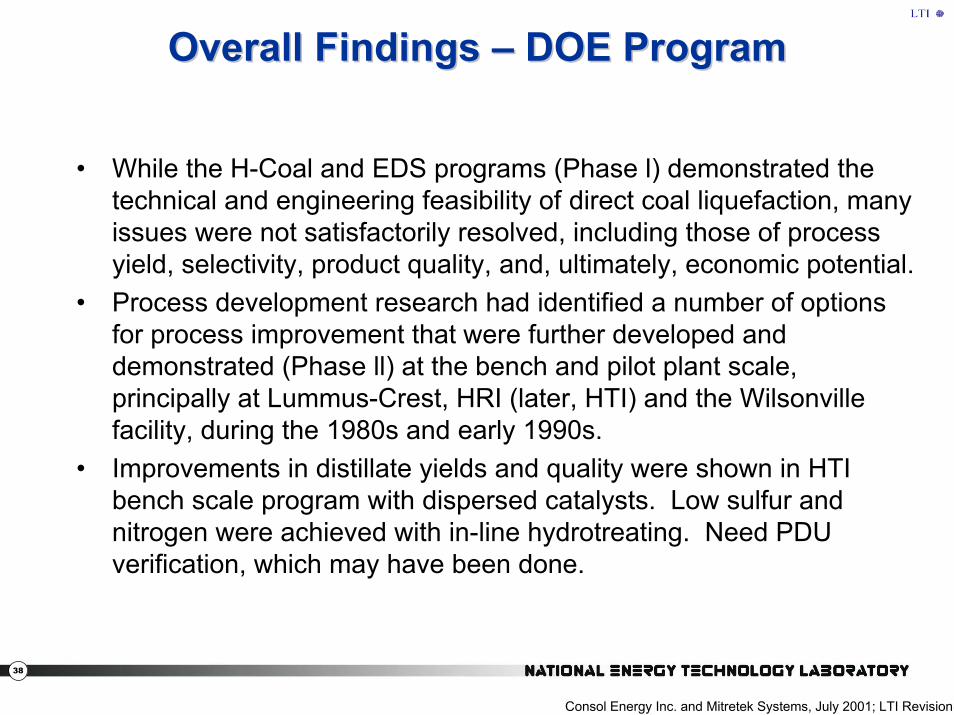
Overall Findings Overall Findings –– DOE ProgramDOE Program
• While the H-Coal and EDS programs (Phase l) demonstrated the technical and engineering feasibility of direct coal liquefaction, many issues were not satisfactorily resolved, including those of process yield, selectivity, product quality, and, ultimately, economic potential.
• Process development research had identified a number of options for process improvement that were further developed and demonstrated (Phase ll) at the bench and pilot plant scale, principally at Lummus-Crest, HRI (later, HTI) and the Wilsonville facility, during the 1980s and early 1990s.
• Improvements in distillate yields and quality were shown in HTI bench scale program with dispersed catalysts. Low sulfur and nitrogen were achieved with in-line hydrotreating. Need PDU verification, which may have been done.
Consol Energy Inc. and Mitretek Systems, July 2001; LTI Revision

39
Overall Findings Overall Findings –– DOE Program (2)DOE Program (2)
High Yields of Distillate Fuels Demonstrated• One of the most important accomplishments of the Phase II work
was a substantial increase in liquid yields compared to the Phase I processes. High liquid yield is important, because direct liquefaction is capital-intensive. Therefore, increasing liquid yields greatly reduced the capital cost component of the process on a dollars/barrel/stream day basis. Liquid fuel yields were increased from 45% to 50% (MAF coal basis) for Phase 1 processes to about 75% (more than 4.5 bbl/t of MAF coal) for Phase 2 processes, while the yields of less valuable gaseous and non-distillate fuels were reduced commensurately for mid-western U.S. (Illinois Basin) coal.
Consol Energy Inc. and Mitretek Systems, July 2001

40
Overall Findings Overall Findings –– DOE Program (3)DOE Program (3)
High-Quality Liquids Produced• The liquids made in the Phase I processes were intended to be
crude oil replacements, but they were unstable, highly aromatic, and had high heteroatom (sulfur, nitrogen, oxygen) contents. This prompted concern about refinability, storage stability, and human health, principally related to carcinogenicity.
• In the Phase II work, considerable attention was paid to improving liquid fuel quality. The Phase II process produces liquid fuels containing no resid, no metals, and low levels of heteroatoms.
• These primary products can be refined in conventional refineries to meet current specifications for motor and turbine fuels. Productquality evaluations, which were an important element of the Phase II work, ensured that acceptable transportation fuels can be produced by direct coal liquefaction.
Consol Energy Inc. and Mitretek Systems, July 2001

41
Overall Findings Overall Findings –– DOE Program (4)DOE Program (4)
High-Quality Liquids Produced• The Phase ll processes make a quality naphtha that can be
processed in conventional refineries into high-quality gasoline. • No undesirable blending interaction with conventional gasolines and
naphthas is expected. Direct coal liquefaction middle distillates can serve as blend stocks for the production of diesel fuel and kerosene.
• The low heteroatom content with accompanying higher hydrogen contents of Phase 2 process products alleviate the carcinogenicity concerns related to Phase 1 process products.
Consol Energy Inc. and Mitretek Systems, July 2001

42
Overall Findings Overall Findings –– DOE Program (5)DOE Program (5)Process Scale-Up Demonstrated• The Phase I work demonstrated successful continuous operation of
plants as large as 200 t/d of coal feed (Ashland Synthetic Fuels, Inc., Catlettsburg, KY)
• The Phase II processes are sufficiently similar to the Phase I processes, in terms of process equipment and unit operations, that this experience is directly applicable.
• In addition, some of the key process equipment, such as the ebullated bed reactor, is used in petroleum refineries around the world.
• Materials of construction and equipment designs were found to overcome corrosion, erosion, and fouling problems experienced inPhase 1 plants; these new materials and designs were demonstrated to be suitable.
• As a result, we can approach the scale-up of the Phase II processes to commercial scale with reasonable confidence.
Consol Energy Inc. and Mitretek Systems, July 2001

43
Overall Findings Overall Findings –– DOE Program (6)DOE Program (6)Direct Liquefaction Shown to Apply to a Wide Range of Coals• One emphasis of the Phase II work was to apply direct liquefaction
to low-rank coals. This is important, because it proved that the huge reserves of inexpensive western U.S. subbituminous coals make excellent liquefaction feedstocks. – Lignite, subbituminous, and bituminous coals from the eastern,
mid-western, and western U.S. were shown to be suitable feedstocks. These represent the vast majority of U.S. coal resources.
• The Phase 2 work showed that direct liquefaction is a flexible process for sub-bituminous and other low rank coals.
• It was shown that direct liquefaction could be applied to a mixed feedstock containing coal and petroleum resids, heavy oil, or bitumen ("coprocessing"), and to coal and waste polymers. This allows a single plant to operate with the most economical feedstock available at a given place and time.
Consol Energy Inc. and Mitretek Systems, July 2001
44
Overall Findings Overall Findings –– DOE Program (7)DOE Program (7)
• Some specific issues that were originally significant problem areas, but that were moderated by improved materials, equipment, or process design during the development program include:- Overall plant reliability- Deashing- Product compatibility with conventional fuels- Let-down valve erosion- Preheater coking- Corrosion in distillation columns
Modified from Consol Energy Inc. and Mitretek Systems, July 2001
45
Direct Coal LiquefactionDirect Coal LiquefactionPrevious DesignsPrevious Designs

46
• During the late 1970’s and early 1980’s designs were prepared for the one stage liquefaction processes– Pilot Plants: H coal, EDS, SRC – Demonstration Plants: SRC-I, SRC-II, H-Coal
• Baseline Design for Direct Liquefaction Plant– May 1990 to February 1995 – Bechtel / Amoco Contractors– Two Stage Liquefaction based on Wilsonville PDU– Plant capacity of roughly 60,000 barrels per day of liquid
products plus C1 – C4 gases.– Considered both Bituminous and sub-bituminous coals
Direct Liquefaction Design Information Direct Liquefaction Design Information
47
• Development of the cost estimate and economics for– the base-line design– alternates for the coal liquefaction facility – compilation of equipment lists and utilities summary– development of scaling factors for equipment size and plant cost– development of the estimates for capital equipment, working
capital, and owner's costs. – The economic analyses includes manpower requirements and
operating costs • Development of mathematical algorithms and models for equipment
sizing, scaleup, costing, train duplication for incorporation into the ASPEN/SP simulation program.
Direct Liquefaction Design Information (2) Direct Liquefaction Design Information (2)

48
• Development of an ASPEN/SP process simulation model of the baseline design. – The model produces complete heat and material balances,
elemental balances around each plant and the entire process complex,
– a major equipment list and outline specifications for the plant sections, utility requirements, capital cost for all plants sections
– a discounted cash flow economics model for the total complex.– The model is suitable for studying technology advances and
options in a case study approach. The model does not feature optimization capabilities.
Direct Liquefaction Design Information (3)Direct Liquefaction Design Information (3)

49
Design information beyond Bechtel Study• HRI Two stage CMSL liquefaction design• NEDO pilot plant design and operation• Shenhua Commercial plant design• Headwaters conceptual designs for India and Indonesia • Information in public domain is minimal
Direct Liquefaction Design Information (4)Direct Liquefaction Design Information (4)

50
Comparison of BaselinesComparison of Baselines
Bechtel Baseline reports

51
The DCL Process is More Complex Than a The DCL Process is More Complex Than a Simple SchematicSimple Schematic

52
DCL Reactor Operating ConditionsDCL Reactor Operating Conditions
Key Operating Conditions for the Coal Liquefaction Reactor Wilsonville
257-J Improved Baseline
Baseline
Coal SV, lb MAF/hr/lb Catalyst 2.17 1.95 1.12 Temp, oF Reactor 1 Reactor 2
809 760
810 760
790 760
Catalyst addition Lbs/ ton MF coal each stage
3/1.5 3/1.5 3/1.5
Solvent/MAF Coal 2.25 2.26 2.46 Resid in Solvent, wt% 50 50 50
Bechtel Baseline reports

53
DCL Product YieldsDCL Product Yields
Overall Liquefaction Product Yields Yields, wt%, MAF Wilsonville
257-J Improved Baseline
Baseline
H2S + H2O + COx +NH3 15.1 13.9 14.0 C1 – C3 5.4 5.5 4.8 C4 – 350 oF 350 – 450 oF
14.5 7.1
15.8 7.3
16.9 7.5
450 – 850 oF 44.2 48.1 46.8 C4+ Liquids 65.8 71.2 71.2 Resid 1.2 0.0 0.0 Organics in ash-concentrate 18.5 15.7 16.3 H2 (6.0) (6.3) (6.2)
Bechtel Baseline reports

54
Capital Cost Mid 1991 dollars
Bechtel Baseline reports
Bechtel Capital CostBechtel Capital Cost

55
Bechtel Capital Cost (2)Bechtel Capital Cost (2)
Bechtel Baseline reports

56
Bechtel Baseline reports
Bechtel Capital Cost (3)Bechtel Capital Cost (3)

57
Bechtel Baseline reports
Bechtel Capital Cost (4)Bechtel Capital Cost (4)

58
Bechtel Baseline reports
Bechtel Capital Cost (5)Bechtel Capital Cost (5)

59
Bechtel SubBechtel Sub--bituminous Coalbituminous Coal
Capital Cost 4th Q 1993 dollars
Bechtel Baseline reports

60
Bechtel SubBechtel Sub--bituminous Coal (2)bituminous Coal (2)
Economics Case COE $/bbl
Low Rank Coal with H2 Production by Coal Gasification
32.75
Low Rank Coal with H2 production from natural gas
33.85
Bechtel Baseline reports

61
Potential Technology VendorsPotential Technology VendorsTechnology Licensor Process
Coal Liquefaction AxensAccelergyChevronHeadwaters/HTI
H-CoalEDS
CMSLBottom solid-liquid separation
Kerr McGee, ConocoPhillips, Exxon
ROSETM de-asphaltingDelayed CokingFluid Coking
H2 (NG Reforming) Foster Wheeler, Kellogg, ICI, Kvaerner, etc.
H2 (coal Gasification)
GE, ConocoPhillips, Shell, Siemens, Lurgi, Southern Co.
H2 Purification UOP PSA/Membrane
LPG Treating UOP Merox
Ammonia Removal USX Phosam-W
Phenol Removal Koch-Glitsch Dephenolization
EPCs: Bechtel, Fluor, Kellogg, Parsons
62
Design Thoughts and IssuesDesign Thoughts and Issues
• Bechtel design does not include updated information for HTI PDU activities and post DOE work
• Carbon footprint was not considered• Technical information and more recent designs
probably done by Headwaters and Axens which would be helpful to update the baseline. – Verification of data may be difficult without
independent experimentation • Active technology developers Headwaters and
Axens (subsidiary of IFP)• Other Technology Developers are working on
advanced direct liquefaction technology – not public knowledge

63
Environmental ConsiderationsEnvironmental Considerations

64
Illinois No. 6 Coal AnalysisIllinois No. 6 Coal AnalysisProximate Analysis wt.%
Volatile Matter 33.0
Fixed Carbon 38.3
Ash 20.0
Moisture 8.7
Ultimate Analysis wt.% Dry
Carbon 61.5
Hydrogen 4.2
Nitrogen 1.2
Sulfur 5.1
Chlorine 0.1
Ash 21.9
Oxygen (by difference) 6.0
Burning Star Mine, ROM Coal Analysis

65
Illinois No. 6 Coal Analysis (2)Illinois No. 6 Coal Analysis (2)Sulfur Forms
Pyrite 38.3
Sulfitic 20.0
Organic 8.7
Ash Composition
P2O5 0.1
SiO2 43.8
Fe2O3 24.1
Al2O3 17.1
TiO2 0.6
CaO 5.6
MgO 1.0
SO3 4.1
K2O 2.1
Na2O 0.6
Undetermined 0.7
Burning Star Mine, ROM Coal Analysis

66
Other Coal ConstituentsOther Coal Constituents
Besides PAHs, coal also contains many toxic inorganic elements such as cadmium (Cd), arsenic (As), lead (Pb), selenium (Se), and mercury (Hg) that might be carried over into liquid fuel products.
67
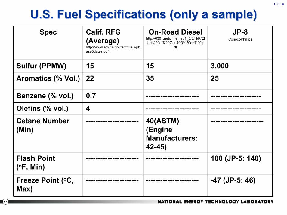
U.S. Fuel Specifications (only a sample)U.S. Fuel Specifications (only a sample)Spec Calif. RFG
(Average)http://www.arb.ca.gov/enf/fuels/phase3dates.pdf
On-Road Dieselhttp://0301.netclime.net/1_5/0/H/K/Effect%20of%20Gen49D%20on%20.p
df
JP-8 ConocoPhillips
Sulfur (PPMW) 15 15 3,000
Aromatics (% Vol.) 22 35 25
Benzene (% vol.) 0.7 ---------------------- ---------------------
Olefins (% vol.) 4 ---------------------- ---------------------
Cetane Number (Min)
---------------------- 40(ASTM) (Engine Manufacturers: 42-45)
----------------------
Flash Point (oF, Min)
---------------------- ---------------------- 100 (JP-5: 140)
Freeze Point (oC, Max)
---------------------- ---------------------- -47 (JP-5: 46)

68
Comparison of DCL and ICL Final ProductsComparison of DCL and ICL Final ProductsDirect Indirect
Distillable product mix 65% diesel35% naphtha
80% diesel20% naphtha
Diesel cetane 42-47 70-75
Diesel sulfur <5 ppm <1 ppm
Diesel aromatics 4.8% <4%
Diesel specific gravity 0.865 0.780
Naphtha octane (RON) >100 45-75
Naphtha sulfur <0.5 ppm Nil
Naphtha aromatics 5% 2%
Naphtha specific gravity 0.764 0.673
Lepinski, Overview of Coal Liquefaction November 2005
Final coal to liquid products meet stringent standards

69
Environmental ConsiderationsEnvironmental Considerations
• Baseline meets environmental standards as of 1990• Waste streams addressed include:
– Solid waste– Waste water (organics including phenols)– Acid gases
• Process equipment to meet the environmental standards included in baseline designs
• Solid waste and waste water use mainly standard equipment for petroleum processing or coal power plants – some novel processing

70
National Coal Council ReportNational Coal Council ReportPlant Type DCL ICL Recycle Hybrid
Coal Consumption 23,044 32,305 25,514STPD dry basis
Liquid ProductsDiesel 45,812 47,687 46,750Naphtha 18,863 22,313 20,591LPG 5,325 0 2,660
Total 70,000 70,000 70,001
Electric PowerImport 282Export 1,139 45
Overall Efficiency (%) 60.1 47.4 58.7
Plant CO2 Generation 783 1,972 1,010(lbs/barrel)
National Coal Council – June 2007

71
National Coal Council Report (2)National Coal Council Report (2)
National Coal Council Report
Plant Type DCL iCL Recycle Hybrid Spec/TypicalConventional ULS Diesel
Diesel Specific gravity 0.865 0.78 0.821 0.82-0.85 Cetane 42-47 70-75 56-61 > 40 Sulfur (ppm) < 5 < 1 < 3 < 15 Aromatics (%) 4.8 < 4 < 4.4 < 35 Heating Value (Btu/Gal) 138,100 129,800 133,950 138,700
Naphtha Specific gravity 0.764 0.673 0.717 0.72-0.78 Octane (RON) > 100 45-75 75-95 85-95 Sulfur (ppm) < 0.5 Nil < 0.3 < 30 Aromatic (%) 5 2 3.5 < 27 Heating Value (Btu/Gal) 133,000 116,690 124,845 124,800
National Coal Council – June 2007

72
Preliminary for Discussion only
LTI Review of NCC DataLTI Review of NCC Data
iCL iCLPlant Type DCL Recycle Once-through Hybrid
Coal Consumption 23,044 32,305 37,974 25,514STPD dry basis
Liquid Products Diesel 45,812 47,687 47,687 46,750 Naphtha 18,863 22,313 22,313 20,591 LPG 5,325 0 0 2,660Total 70,000 70,000 70,000 70,001
Electric PowerImport 282Export 1,018 1,139 45
Overall Efficiency (%) 60.1 48.4 47.4 58.73
Plant CO2 Generation 783 1,557 1,972 1,010 (lbs/barrel)
Plant CO2 Generation with sequestration for gasification 369 217 275
National Coal Council – June 2007; Additional information LTI

73
Current Technology Current Technology DevelopmentsDevelopments

74
Shenhua DCL ProjectShenhua DCL Project

75
DCL ScaleDCL Scale--up and Commercial Developmentup and Commercial Development
Lawrenceville, NJ30 bpd
Catlettsburg, KY1800 bpd
Inner Mongolia, China17,000 bpd
Lepinski, Overview of Coal Liquefaction November 2005

76
Shenhua DCL ProjectShenhua DCL ProjectLight gases
Gasoline
Jet Fuel
Diesel
Catalyst
N2
Air
Recycle Solvent
Residue
O2
H2
Coal Prep
Slurry mixing
Liquefaction
Separation
Upgrading
Fractionation
Air Separation
Gasification
Purification
"Shenhua Direct Coal Liquefaction Process
"First Train: 1 MT/a Liquefaction oil
Shenhua Group, 2006

77
Axens HAxens H--Oil and Coal Liquefaction ReactorsOil and Coal Liquefaction Reactors
78
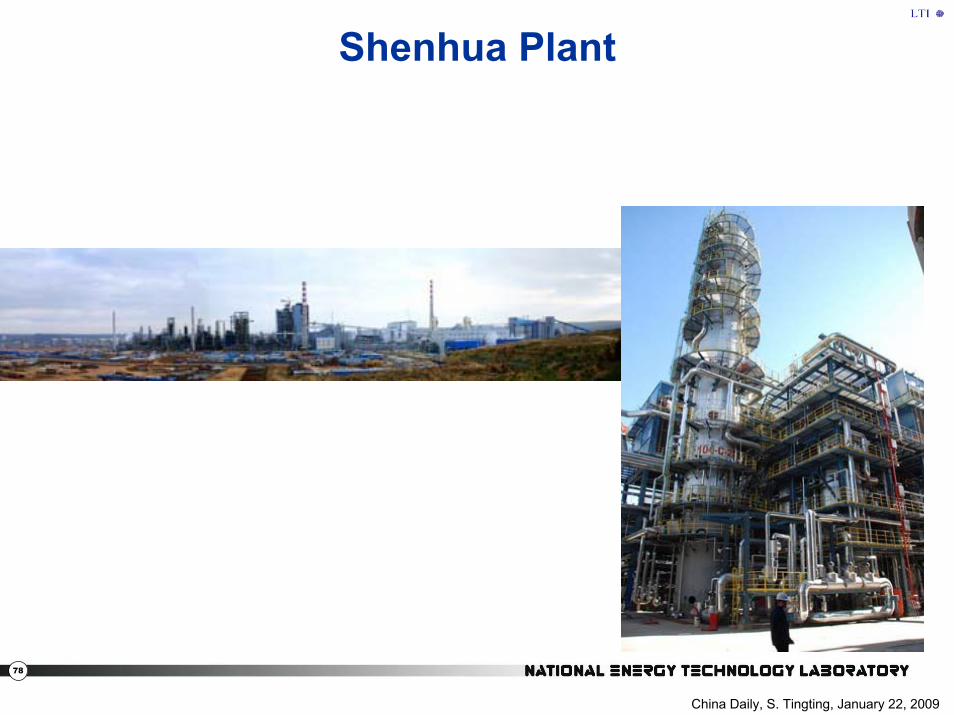
Shenhua Plant
China Daily, S. Tingting, January 22, 2009

79
Speculations About Shenhua DCL PlantSpeculations About Shenhua DCL Plant
• Direct liquefaction– Conversion and hydrocracking to oils
– Two reactors in series• Purpose: conversion and hydrocracking to oils• slurry catalyst• Expanded bed reactors (probably slurry)
– Solvent Hydro-treating (?) and upgrading• Ebullated Bed (H-Oil)• Hydrotreating• Recycle solvent hydro-treating (?)• Manufactured petroleum catalyst (Co-Mo or Ni-Mo)

80
Shenhua PatentShenhua Patent
• According to a preferred embodiment of the invention, a test of direct coal liquefaction is performed using a low rank bituminous coal as feedstock, and the operation conditions and test results are as follows:
• Test operation conditions: – Reactor temperature: 1st reactor 455°C, 2nd reactor 455°C; – Reactor pressure: 1st reactor 19.0MPa, 2nd reactor 19.0MPa; – Slurry coal concentration: 45/55(dry coal/solvent, mass ratio); – Catalyst addition rate: Liquefaction catalyst: 1.0 wt %(Fe/dry
coal); – Sulfur addition rate: S/Fe=2(molar ratio); – Gas/liquid: 1000NL/Kg slurry; – Hydrogen in the recycle gas: 85vol %.
A PROCESS FOR DIRECT LIQUEFACTION OF COAL, European Patent EP1783194

81
Shenhua Patent (2)Shenhua Patent (2)The results of direct coal liquefaction of a low rank bituminous coal in a CFU test unit of the invention is shown in Table 1, wherein the figures in the table are based on MAF coal. The results of the same kind of coal tested in another direct coal liquefaction CFU is shown in Table 2, wherein the figures in table 2 are also based on MAF coal.
Table 1. Direct coal liquefaction results of a
low rank bituminous coal in a CFU unit
Conversion %
Oil yield
%
Gas yield
%
H 2 O yield
%
Organic residue %
H 2 consumption
% Process of the invention 91.22 57.17 13.11 12.51 23.99 6.8
Table 2. Direct coal liquefaction results of a
low rank bituminous coal in a CFU unit
Conversion %
Oil yield
%
Gas yield
%
H 2 O yield
%
Organic residue %
H 2 consumption
% Process of the prior art 89.69 52.84 17.89 7.3 28.1 6.75
A PROCESS FOR DIRECT LIQUEFACTION OF COAL, European Patent EP1783194

82
Shenhua Information on PDUShenhua Information on PDU
• Coal to liquid fuels product data– Naphtha product: 0.748-0.758 g/cm3– N < 0.5 ppm (wt)– Jet fuel: smoke point, 25mm, minimum– Naphthene < 0.1wt%– High density
• Table of diesel product results
Diesel A Diesel B Density 0.866 0.86 S (mg/g) 1.8 (< 5ppm) < 5 ppm Aromatics % 4.5 4.6 Carbon % 86.66 86.67 Cetane # 43.3 43.9
U.S. DOE, M. Ackiewicz, Notes 2009

83
The Brown Coal Liquefaction Process

84
Source: Sojitz, CTLtec 2008

85
Gas
SlurryBedReactor
FixedBedReactor
Liquefaction In-line Hydrotreating1st 2nd
CLB !"#$%&'"(
Recycle Solvent"""!")%%* #$%&"(
Coal Slurry
Distillation
Gas-Liquid Separater
GasolineKeroseneGas Oil
Fig. Conceptual flow of In-line hydrotreating section
Brown Coal Liquefaction ProcessBrown Coal Liquefaction Process
Source: Sojitz, CTLtec 2008

86
• The BCL process was developed by NEDO of Japan to a 50 tonnes/day pilot-plant scale, constructed at Morwell in Victoria, Australia.
• The process is designed specifically to handle very low-rank coals such as those found in the Latrobe Valley of Victoria, which maycontain >60% moisture.
• It was operated over the period 1985-1990, processing a total of ~60,000 tonnes of coal. Operations ceased in October 1990.
• The plant was decommissioned in 1991 and demolished in 1992.• A crucial aspect is the efficient drying of the coal. The 50 tonnes/day
rated throughput of the pilot plant required ~170 tonnes/day of raw coal to be processed.
• Following extensive pilot plant operation, R&D using a 0.1 tonnes/day bench-scale continuous liquefaction test facility and related equipment was carried out until 1997 to improve the reliability, economics and environmental compatibility of the coal liquefaction process.
Brown Coal Liquefaction Process (2)Brown Coal Liquefaction Process (2)
Dept. of Trade and Industry (U.K.), October, 1999

87
• Based on the R&D results an improved BCL process was proposed. This comprises slurry de-watering, liquefaction, in-line hydrotreating, and de-ashing, with the following features: – use of a high-active and inexpensive catalyst such as limonite
ore pulverized in oil– use of a heavy fraction solvent (bp 300-420ºC)– adoption of coal liquid bottom (CLB) bp>420ºC recycling
• Compared with the results of the pilot plant, the increase of oil yield, improvement of product oil quality and suppression of scale formation in reactors were proved using the bench-scale unit with <1% (dry ash-free coal) catalyst addition.
• It was estimated that the improved process could decrease the crude oil equivalent nominal price by 24% compared with the BCL process at the Australian pilot plant.
• Yields are stated to be 65% distillate. • A new cooperation agreement was started between Japan (Sojitz)
and Indonesia in 2005 to build a 27,000 BPD plant
Dept. of Trade and Industry (U.K.), October, 1999, Sojitz CTLtec -2008
Brown Coal Liquefaction Process (3)Brown Coal Liquefaction Process (3)

88
Source: Sojitz, CTLtec 2008
89
Hybrid DCL/ICL Plant ConceptHybrid DCL/ICL Plant Concept

90
Hybrid DCL/ICL Plant ConceptHybrid DCL/ICL Plant Concept
Coal
Raw ICL products
Raw DCL products
H2
H2
FT tail gas
Final Products
CoalGasification
Indirect CoalLiquefaction
(FT)
Product Blending and
Refining
HydrogenRecovery
Direct Coal Liquefaction
DCL Bottoms
Lepinski, Overview of Coal Liquefaction November 2005

91
• C3-C4 18 %• F-T naphtha 19 %• DCL Naphtha 26 %• F-T diesel 22 %• DCL distillate 10 %• DCL VGO 5 %
Hybrid Plant Theoretical Product YieldsHybrid Plant Theoretical Product Yields
Lepinski, Overview of Coal Liquefaction November 2005

92
Accelergy ConceptAccelergy Concept

93
Accelergy ConceptAccelergy Concept
Accelergy ConceptAccelergy Concept
Accelergy; http://www.accelergy.com/CTLprocess.phpAccelergy; http://www.accelergy.com/CTLprocess.php

94
LTI LTI Thoughts and CommentsThoughts and Comments

95
Potential Merits of Direct Coal LiquefactionPotential Merits of Direct Coal Liquefaction
• DCL produces high octane gasoline• DCL has higher thermal efficiency than indirect
liquefaction• Literature suggests that DCL with no CCS may have a
lower carbon footprint• Opportunity for combined coal and renewable energy
processes with improved carbon footprint and carbon management
• Synergistic opportunities– Hybrid direct/indirect technology integration– Coprocessing with biomass (Hydrogen production)– Coprocessing with heavy oil/refinery bottoms/wastes(?)

96
Thoughts and IssuesThoughts and Issues
• LTI reviewed documents/analyses of direct liquefaction technology, design and current data where available
• General findings and conclusions– Review of the past DOE R,D&D program generally
agrees with the analysis and findings of Burke, Gray and Winschel, et al (2001)
– Significant progress has been made in achieving improved yield of distillate and product quality
– Reliability of operation of components has been increased

97
Thoughts and Issues (2)Thoughts and Issues (2)
– Operation issues and readiness are still believed to be less than Indirect technologies and are a major concern
– Bechtel design for bituminous and sub-bituminous coals were thoroughly done and are authoritative
• Were based on Wilsonville data and are still considered reasonably up to date, however:
– Capital cost and economics must be revised – To the extent possible recent HTI and other data should
be considered– Carbon footprint and carbon management were not
considered

98
Thoughts and Issues (3)Thoughts and Issues (3)
– HTI CMSL data with highest distillate results and later experimentation at the bench scale with coal and coal and other feedstocks (mixed plastics) needs further evaluation at the PDU scale to be considered highly reliable (this may have been done by HTI and others after the DOE program)
– Recent HTI results (for example) would meet current specifications for diesel and gasoline after significant hydrotreating

99
Thoughts and Issues (4)Thoughts and Issues (4)
• Bechtel Baseline Design (1993) does not include updated information for HTI PDU activities and post DOE work
• Post Bechtel design information particularly CMSL provides hope for increased distillate but this is confounded by the many variables that effect yields and the small scale at which the data was generated
• The low sulfur and nitrogen content of the distillate achieved in the CMSL was due to in-line hydrotreating and lighter distillate
• Technical information and more recent designs probably done by Headwaters and Axens would be helpful to update the baseline. – Verification of data may be difficult without independent experimentation – Technology developers Headwaters and Axens (subsidiary of IFP) are
actively seeking partners for direct liquefaction projects– It also appears that Shenhua, Sojitz as well as others are in some stage
of planning or marketing their technology

100
Thoughts on Present ConceptsThoughts on Present Concepts
• There is still competition for what is the preferred direct liquefaction Technology
• NEDO and Accelergy (possibly) are proposing single stage liquefaction through the primary use of a hydrogen donor solventtreated in a separate reactor
• Shenhua is supporting a combination of dispersed catalyst for liquefaction (single stage) and may be utilizing hydrogen donor solvent catalytically hydrotreated in separate reactors (H-Oil)
• HTI (and others?) are supporting two stage liquefaction (separate stages for coal dissolution and upgrading of the resulting oils). The technology likely incorporates use of either manufactured catalyst or dispersed catalyst
• Concepts are either providing a distillate crude for refinery upgrading or producing specification gasoline, diesel, jet fuel products. In either case, in-hydrotreating is being used in current technology.

101
Thoughts on Present Concepts (2)Thoughts on Present Concepts (2)
• It appears that current direct liquefaction distillate products can meet the existing fuel standards
• Concepts must have a strategy for waste product (liquefaction bottoms) use or disposal
• Configurations with liquefaction, upgrading, hydrotreating and ash separation will produce high yield, good quality products but are complex, highly integrated and capital intensive
• Need carbon management strategy, e.g. capture and sequestration of carbon produced during hydrogen production and/or use of renewable energy for hydrogen production or cofeeding

102
• Other technology developers are working on advanced direct liquefaction technology – not public knowledge
• Similar to other complex conversion technologies, EPC contractors are available – Need track record in complex and large (multi $ billion) projects
• Specialized high pressure equipment vendors for reactors and components (slurry pumps, let-down values) are limited and probably foreign based (India/China)
• Shenhua could be useful source of information –material may not be available to public. WVU could facilitate obtaining information.
Thoughts on Present Concepts (3)Thoughts on Present Concepts (3)

103
Direct Liquefaction Technical NeedsDirect Liquefaction Technical Needs
• Advanced concepts• Reduce carbon footprint• Combination coal and renewable energy concepts• Co-feeding concepts• Less severe processing
– Lower capital and process cost• Product integration with refinery or finished distillate
products• Component material and reliability studies

104
System Analysis NeedsSystem Analysis Needs• Perform carbon LCA for DCL using available data
(Bechtel design study, e.g.) and compare with ICL• Compare carbon LCA for two stage liquefaction with
advanced one stage with separate reactor for hydrogenation of recycle hydrogen donor solvent
• Evaluate advanced concepts with reduced carbon footprint– Determine the benefits for producing hydrogen from
non-carbon producing sources including biomass– Determine the benefits of hybrid concepts (combined
direct and indirect liquefaction)– Determine the direct liquefaction opportunities for
carbon capture and storage and other carbon management techniques

105
System Analysis Needs (2)System Analysis Needs (2)
• Direct Liquefaction Data Validation– Evaluate and confirm direct liquefaction data post
DOE program• Two-stage liquefaction current concepts• Single stage
– Compare catalyst and reactor types for direct liquefaction
• Ebullated or slurry reactors• Manufactured or dispersed catalysts
– Verify improved DCL product quality results (beyond that achieved in DOE program)

106
System Analysis Needs (3)System Analysis Needs (3)
• Shenhua Plant Operation – Confirm process operation (yields & quality)– Evaluate component reliability– Improve understanding of process configuration– Recognize that data may not be available in the
public domain

107
R&D NeedsR&D Needs
• Verify by R&D Process and Product improvements– Verify improved DCL product quality results (beyond achieved in
DOE program)– Hybrid Studies
– Process and product optimization– Product characterization and compatibility
• Verify liquid products meet health and safety standards for commercial use
• Explore technologies to reduce water consumption• Evaluate potential technologies that offer lower life cycle carbon
footprint– Use of renewable feedstock or energy for hydrogen or synthesis– Integration with carbon management techniques

108
• Summary Report of the DOE Liquefaction Process Development Campaign of the Late Twentieth Century: Topical Report, Consol Energy Inc. and Mitretek Systems, July 2001
• Technologies to Reduce or Capture and Store Carbon Dioxide Emissions, The National Coal Council, June 2007
• Coal Liquefaction: A research Needs Assessment, Department of Energy, February 1989
• Coal Liquefaction – Technology Status Report Department of Trade and Industry, Great Britain, October 1989
• Direct Liquefaction Proof of Concept Facility, HRI/HTI, A.G. Comolli el al, Technical Progress Report – POC Run 1, Contract No. 92PC92148, August 1996
• Direct Liquefaction Proof of Concept Facility, HRI/HTI, A.G. Comolli el al, Technical Progress Report – POC Run 2, No. 92PC92148, December 1996
ReferencesReferences

109
• Catalytic Multistage Liquefaction of Coal, HTI, A.G. Comolli el all, Technical Progress Report – Ninth Quarterly Report, No. 92PC92147, June, 1995
• Catalytic Multistage Liquefaction of Coal at HTI, HRI/HTI, V.R. Pradhan el al, Coal and Gas Conversion Contractors’ Review Conference, Contract Report, No. 92PC92147, August, 1995
• Direct Coal Liquefaction Baseline Design and System Analysis; Executive Summary, Volume 1-7, Bechtel, Amoco, Contract No. 90PC89857, March 1993
• Direct Coal Liquefaction Low Rank Coal Study; Executive Summary,Study, Bechtel, Amoco, Contract No. 90PC89857, February 1995
• Direct Coal Liquefaction Low Rank Coal Study; Executive Summary,Final Report on Design, Capital Cost and Economics for the Low Rank Coal Study, Bechtel, Amoco, Contract No. 90PC89857, February 1995
• Improved Brown Coal Liquefaction (BCL) Process, Sojitz Corp. at CTLtec America’s Conference, June 23-24, 2008, Pittsburgh, PA. Note: Refer also to the following NEDO, Japan website:
http://www.nedo.go.jp/sekitan/cct/eng_pdf/2_3a3.pdf
References (2)References (2)
110
• Overview of Coal Liquefaction, James Lepinski, Headwaters Incorporated, U.S. India Coal Working Group Meeting, Washington DC, November 2005
• Direct Coal Liquefaction: Lessons Learned, R. Malhotra, SRI International, GCEP Advanced Workshop, BYU, Provo, UT, March 2005
• Overview of Coal-to-Liquids, J. Marano, consultant; presentation to NETL, April, 2006
• Chemistry of Coal Liquefaction; Second Supplementary Volume, Martin Elliott, editor, 1981, John Wiley & Sons, Inc., Chapters 27/28/29
• Technology Status Report 010: Coal Liquefaction; Dept. of Trade and Industry (U.K.), October, 1999
• Accelergy: –– http://www.accelergy.com/CTLprocess.phphttp://www.accelergy.com/CTLprocess.php
• China Daily; S. Tingting, January 22, 2009– http://www.chinadaily.com.cn/bizchina/2009-01/22/content_7419616.htm
References (3)References (3)


![Direct Coal Liquefaction - worldpetrocoal.inworldpetrocoal.in/download/6th-WPCC-2016-PPT/Day2/S-VI/Ankit-Jain.… · World coal reserves [2] Coal liquefaction [3] [1] Ivanhoe, L.F.,](https://img.pdfslide.us/doc/110x75/5afab7327f8b9a44658f658c/direct-coal-liquefaction-world-coal-reserves-2-coal-liquefaction-3-1-ivanhoe.jpg)