Embed Size (px)
Citation preview

Since 1950DIAMANTPRODUKTER AB
OP
ER
AT
ION
GU
IDE
- C
LA
SS
IC
WARNING:Give this operation guide to the operator of the machine.
To reduce the risk of injury the operator must read and fully understand the Instructions in the Operation Guide before using
or repairing the machine.
Diprofil Classic Polishing/Filing Machine

2
www.diprofil.com

3
www.diprofil.com
TABLE OF CONTENTS:
Introduction 4Available models 5 Safety instructions 6Technical data 8Operating Instructions 10Service and maintenance 12Vibration emission 14Vibration declaration statement 15Additional vibration information 16

4
www.diprofil.com
INTRODUCTION
Thank you for choosing a Diprofil product. Since its introduction on the world market in 1950, the Classic Diprofil machine has become an indispensable part of the equipment needed for tool making.
The Classic machines are designed for polishing and finishing applications of moulds and dies, but may also be used for other fine mechanical applications such as de-burring and filing.
The following safety and operation guidelines are intended for your safety and to get the maxi-mum value from your machine in terms of efficiency, life expectancy and ergonomics.
Before using the machine, the operator must read and fully understand the instructions included in this operation guide.
List of spare-parts available at www.diprofil.com

5
www.diprofil.com
DIPROFIL CLASSIC MACHINES - AVAILABLE MODELS
A. FLEXIBLE SHAFT-DRIVEN MACHINES Type FPK/R, FPS/R and FPH/R
B. AIR DRIVEN MACHINE Type FPL/R
C. MICRO MOTOR-DRIVEN MACHINES Type FPM/R and FPM/ERJ
D. MACHINES WITH MICRO MOTOR CONNECTION Type FPT/ER and FPT/NR
Package includes:1 x Classic polishing/filing machine1 x Bottle of lubricating oil type FNA-K1 x 3mm Allen-key1 x 2.5mm Allen-key1 x FXA-104 tool-holder extension pipe2 x FXA-106 spare lubricating felts2 x FXA-103 spare guide bushings2 x 42055 spare tool locking screws1 x SGX-100 maintenance tool1 x SGX-101 maintenance tool1 x SGX-102 maintenance tool

6
www.diprofil.com
SAFETY INSTRUCTIONSWARNING = Indicates a potentially hazardous situation which, if not avoided, may result in a serious injury.
CAUTION = Indicates a potentially hazardous situation which, if not avoided, may result in a minor or moderate injury.
MACHINE AND TOOL HAZARDSCAUTIONStarting the machine without the machine cover may cause personal injury.
CAUTIONStarting the machine when changing tool or stroke length may cause personal injury.
CAUTIONAn incorrectly inserted tool may result in the tool slipping out during operation and cause per-sonal injury. Before inserting the tool make sure that the shank dimension is correct. Because of the multi-functional tool holder, it is important that the chosen tool is tightened properly and that the speed chosen is not too high. Try to avoid using heavier tools and longer stroke length than necessary for the specific application.
CAUTIONUnintentional start of the machine may cause injury.
PROJECTILE HAZARDCAUTIONDuring lapping or filing, particles from the working material or tools can become projectiles and cause injuries to eyes or skin. Use approved personal protective equipment, including safety glasses.
NOISE HAZARDCAUTIONNoise ≤ 70 dB(A) at 7.000 strokes/min.
For lengthy use, ear protection is recommended.

7
www.diprofil.com
VIBRATION HAZARDWARNINGNormal and proper use of the machine exposes the operator to vibration.
Regular and frequent exposure to vibration may cause, contribute to, or aggravate injury or disorders of the operator’s fingers, hands, wrists, arms, shoulders and/or permanent injuries or disorders that may develop gradually over periods of weeks, months or years. Such injury or disorder may include damage to the blood circulatory system, damage to the nervous system, damage to joints and possibly damage to other body structures.
If numbness, tingling, pain, clumsiness, weakened grip, whitening of the skin or other symp-toms occur at any time, when operating or not operating the machine, do not resume opera-tion of the machine, but seek medical attention. Continued use of the machine after the occur-rence of any such symptom may increase the risk of symptoms becoming more severe and/or permanent.
WARNINGNever hold hand or fingers on moving machine parts or tools. Moving tools or parts of the tool holder have, when touched, very high levels of vibration.
These vibrations values have been measured and we have obtained the following results:
Note! On the moving tool and at recommended speed: 5.000-6.000 strokes/min the vibration values are very high. At stroke length 1 mm, approx. 20-28 m/s2, at stroke length 2 mm ap-prox. 35-50 m/s2 and at stroke length 3 mm approx. 55-75 m/s2.
CAUTION To keep the vibrations as low as possible it is also of utmost importance to work as parallel as possible to the surface on which the machine and tool will be used. Flexible tools generate less vibration than hard tools as Polishing Stones, Diamond files, etc.
Let the tool do the job. Use minimum possible hand grip consistently with proper control for safe operation.
Note! For information about vibrations and the responsibilities of the manufacturer, the em-ployer and the operator respectively please see information on page 18.
ADDITIONAL SAFETY INSTRUCTIONS
• Machines and accessories must only be used for their intended purpose.
• Only qualified and trained personnel may operate or maintain the machine.
• The maximum permissible machine using data must not be exceeded.

8
www.diprofil.com
TECHNICAL DATA
B. AIR-DRIVEN MACHINEType FPL/R
TECHNICAL DATA Driving:
Speed (maximum):Speed (recommended):Stroke length:Stroke length (recommended):Tool holder:Weight of inserted tool:Applied feed force:Machine weight:Noise level:Vibration levels:
Warning
These models are driven by an electrical motor with speed control and a flexible shaft with slip-joint (European standard) or ball-joint connection (US standard) e.g. Diprofil type DSE-47. Corresponding motors of other brands may also be used.8.000 strokes/min.5.000 – 6.000 strokes/min0 – 6 mm. 0,5 - 3 mm. Ø 6,4 mm. (suitable for tool shanks Ø 2 - Ø 6,4 mm)Maximum: 26 g. Recommended: 1-15 g.2-12 N (depending on inserted tool type and dimension.)Approx. 575 g. (depending on model.)Not exceeding 70 dB(A) at 7.000 strokes/min. According to ISO 15744.See information on page 14.
TECHNICAL DATA Driving:
Connection:
Oil consumption: Air pressure:Air consumption:Speed (maximum):Speed (recommended):Stroke length:Stroke length (recommended):Tool-holder:Weight of inserted tool:Applied feed force:Machine weight:Noise level:Vibration levels:
Warning
This model is driven by compressed and oil mist lubricated air. PLEASE NOTE! The built-in air-motor may be damaged, if operated with un-lubri-cated air.The Diprofil quick-coupling HSL-M and fog lubrication unit MFB should be used for con-nection to your compressed air system. PLEASE NOTE! Protect the air inlet from dust and dirt, when not in operation.Minimum 30mm³/min at maximum speed (about 2 drops/min.)4bar (58psi).Approx. 65 l/min at 8. 000 strokes/min.8.000 strokes/min.5.000 – 6.000 strokes/min 0 – 6mm. 0,5 - 3 mm. Ø 6,4 mm. (suitable for tool shanks Ø 2 - Ø 6,4 mm)Maximum: 26 g. Recommended: 1-15 g.2-12 N (depending on inserted tool type and dimension.)Approx. 740g.Not exceeding 70 dB(A) at 7.000 strokes/min. According to ISO 15744.See information on page 14.
A. FLEXIBLE SHAFT-DRIVEN MACHINESType FPK/R, FPS/R and FPH/R

9
www.diprofil.com
TECHNICAL DATA C. MICRO MOTOR-DRIVEN MACHINES
Type FPM/R (Diprofil connector) and FPM/ERJ (Eneska 3-1 connector)TECHNICAL DATA Driving:
Speed (maximum):Speed (recommended):Stroke length:Stroke length (recommended):Tool-holder:Weight of inserted tool:Applied feed force:Machine weight:Noise level:Vibration levels:
Warning
These models are driven by a built-in micro-motor, which is connected to, and controlled by, the DIPROFIL DPU-3, TPU-20 or corresponding power unit.Output: DC 0-32V.Approx.7.000 strokes/min. (depending on the power unit)5.000 – 6.500 strokes/min 0 – 6 mm.0,5 - 3 mm. Ø 6,4 mm. (suitable for tool shanks Ø 2 - Ø 6,4 mm)Maximum: 26 g. Recommended: 1-15 g.2-12 N (depending on inserted tool type and dimension.)715 g. Not exceeding 70 dB(A) at 7.000 strokes/min. According to ISO 15744.See information on page 14.
D. MACHINES WITH MICRO MOTOR CONNECTION
Type FPT/ER (for Eneska 4-1 and NSK ESPERT) and FPT/NR,(for Eneska 3-1, 3-2 and NSK EMax-Evolution)
TECHNICAL DATA Driving:
Speed (maximum):Speed (recommended):Stroke length: Stroke length (recommended):Tool-holder:Weight of inserted tool:Applied feed force:Machine weight:Noise level:Vibration levels:
Warning
These models should be driven by motors with low strokes/min and high torque only. Exceptions can be made for motors with high torque from very low strokes/min, as e.g. Diprofil motor HPM-BL1 brushless motor for Power Unit TPU-20 or corresponding power unit. Output: BL DC 0-32V or DC 0-32V.Approx. 7.000-8.000 strokes/min. (depending on the power unit)5.000 – 6.500 strokes/min 0 – 6 mm. 0,5 - 3 mm. Ø 6,4 mm. (suitable for tool shanks Ø 2 - Ø 6,4 mm)Maximum: 26 g. Recommended: 1-15 g.2-12 N (depending on inserted tool type and dimension.)Approx. 560 g. (without micro motor).Not exceeding 70 dB(A) at 7.000 strokes/min. According to ISO 15744.See information on page 14.
NOTE! Please keep in mind that higher speed, longer stroke length and heavier tools will generate higher levels of unwanted vibrations.
More information available at www.diprofil.com

10
www.diprofil.com
OPERATING INSTRUCTIONSAll types of polishing/filing machines wear out faster if they are used at high rpm and with heavy tools. The applied feed force and dirt coming into the machine also affects the life expectancy.
FIXATION OF TOOLS:
Place the tool in the tool-holder locking it with the screw (42055). See Fig.1.
STEERING BLOCK:The tool-holder may be used in both a locked and a swiveling mode. To release the guide block (FXA-107): Loosen the screw (42001), pull out the steering block approx. 3 mm and tighten it with the screw in its new position. See Fig. 2.
Fig. 1
Fig. 2
11
www.diprofil.com
STROKE LENGTH ADJUSTMENT:
1. To avoid that the machine is started by mistake the machine must be put out of operation in a secure way before adjusting the stroke length.
2. Remove the machine cover (FMM-3).
3. Loosen the screw (FNE-61) on the adjustable eccentric FMM-17 by means of a 3 mm Allen-key, set the eccentric part in its new position and lock the screw (FNE-61). Reassemble the ma-chine cover, whereafter the work may be started. See Fig. 3.
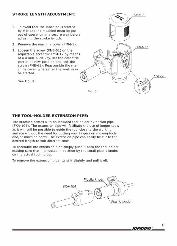
THE TOOL-HOLDER EXTENSION PIPE:The machine comes with an included tool-holder extension pipe (FXA-104). The extension pipe will facilitate the use of longer tools as it will still be possible to guide the tool close to the working surface without the need for putting your fingers on moving tools and/or machine parts. The extension pipe can easily be cut to the desired length to suit different tools.
To assemble the extension pipe simply push it onto the tool-holder making sure that it is locked in position by the small plastic knobs on the actual tool-holder.
To remove the extension pipe, twist it slightly and pull it off.
Fig. 3

12
www.diprofil.com
SERVICE AND MAINTENANCERegular maintenance is a prerequisite for keeping the machine safe and effective. Carefully follow the operating instructions as well as the daily maintenance guide-lines.
Exchange worn parts, like tool holder, ball bearings, etc. Worn parts increase the vibration levels in the machine.
DAILY MAINTENANCE:The below procedure should be carried out approximately every 8 hours of operation.
1. Remove the Machine cover (FMM-3).
2. Apply a few drops of lubrication oil, type Diprofil FNA-K or equivalent, to the needle bearing in the linkage (FNE-102) approximately every 8 hours of operation.
3. Loosen the connecting rod screw (42053). Please make sure not to loosen the screw too much.
4. Release the piston rod and tool holder (FXA-V) by sliding it out of the machine housing.
5. Clean the piston rod and tool holder (FXA-V) carefully with a soft cloth and apply a few drops of lubrication oil, type Diprofil FNA-K or equivalent, according to fig 4 and 5.
6. Reassemble the piston rod and tool holder (FXA-V) into the machine housing, making sure that the piston rod goes all the way to the bottom of the linkage. Lock it with the connecting rod screw (42053).
7. Reassemble the machine cover (FMM-3). See Fig. 5
Fig. 5
Fig. 4

13
www.diprofil.com
Fig. 6
REPLACEMENT OF THE LUBRICATING FELT AND THE PLASTIC GUIDE BUSHING1. Remove the machine cover and the piston rod and tool-holder according to the description
for daily maintenance.
2. Slide the tool (SGX-102) onto the tool-holder.
3. Squeeze/compress the tool (SGX-100) and put it inside the tool-holder making sure that it gets a sufficient grip of the guide bushing (FXA-103).
4. Make sure that the 2 screws (42000) are perfectly aligned with the plastic knobs on the actual tool-holder. Tighten both screws all the way to the bottom by means of a 2,5 mm Allen-key to release the guide bushing (FXA-103) from the outer sleeve of the tool-holder.
5. Then pull the guide bushing out of the tool-holder.
6. Remove the old lubricating felt (FXA-106) and replace it with a new one (make sure that it is drenched in oil, type Diprofil FNA-K or equivalent). See Fig. 6
Fig. 7
7. Squeeze/compress the new guide bushing (FXA-103) and press it about 5 mm into the tool-holder (the knobs should be pointing inwards and towards the machine housing).
8. Then push it all the way to the bottom by means of the tool (SGX-101) making sure that both the plastic knobs are popping out of the small holes on the outer sleeve of the tool- holder. If you are experiencing problems with aligning the knobs with the holes, use the tool (SGX-100) to swivel the guide bushing until they become aligned and the knobs pop out of the holes.
9. Reassemble the machine cover and the piston rod and tool-holder according to the description for daily maintenance.
See fig. 7

14
www.diprofil.com
VIBRATION EMISSION:
The vibration emission value for this machine has been measured at three different hand positions (also see fig. 8 and 9) according to the valid standard, ISO 28927-8:2009/AMD 1:2014 Polishing and filing machines with reciprocating movement. It is expressed in m/s².
The uncertainty value (K) is also expressed in m/s² and is intended to compensate for dif-ferent batches, production variations etc.
Measured vibration emission values:
Hand position 1: 6,02 m/s² (K = 1,09 m/s²)
Hand position 2: 5,79 m/s² (K = 1,15 m/s²)
Hand position 3: 13,37 m/s² (K = 1,82 m/s²)
Fig. 8
Fig. 9
Warning

15
www.diprofil.com
VIBRATION DECLARATION STATEMENTGENERAL INFORMATION:Reciprocating machines all generate potentially harmful vibrations to different extents.
Note! The size and weight of the used tool affects the vibrations very much. There-fore it´s important to use as small and lightweight tools as possible.
The following factors affect the level of unwanted and potentially harmful vibrations transmitted to the hand of the operator.
1. The speed (number of strokes / minute). This is the factor which has the biggest affect on the vibration levels and when operating the machine, it should not be used at speed levels higher than required.
2. The stroke length. The stroke length should be kept as short as possible and adapt-ed to the application.
3. The weight of the used inserted tool. The heavier the tool the higher levels of unwanted vibrations. Using a heavier tool normally means that the speed and the stroke length must be reduced.
4. The angle in which the machine (working tool) is held against the working surface and the tool type: To keep the vibrations as low as possible it is also of utmost importance to work as parallel as possible to the surface on which the machine and tool will be used. Flexible tools as Fibre Stones or articulated tools as Ball-rods together with Lapping Bits and similar generate less vibration than hard tools as Polishing Stones, Diamond files, etc.
Never hold hand or fingers on moving machine parts or tools.
Worn out parts generate vibrations and need to be replaced regularly.

16
www.diprofil.com
ADDITIONAL VIBRATION INFORMATION This power tool may cause hand-arm vibration syndrome, if not adequately used. This ad-ditional vibration information may be of assistance to employers in meeting their obligations e.g. under national law or regulations based on the EU directive 2002/44/EC, to assess the risks to their workers arising from hand-arm vibration exposure associated with the use of this machine.
VIBRATIONS AND THE ISSUE OF HAVS (HAND ARM VIBRATION SYN-DROME)• The EU directive (2002/44/EC) concerning vibration exposure was approved by the member
states and EU parliament in July 6, 2002 and should have been introduced into national laws not later than by July 6, 2005.
• Minimizing the vibration exposure is the responsibility of the manufacturer, the vendor, the employer and the operator respectively.
• When using machines resulting in an exposure exceeding 2,5 m/s2 it is the responsibility of the employer to make an action plan on how to minimize the vibration exposure for the operators. This also includes regular scheduled health inspections.
• Vibrations emission exceeding 2,5 m/s2 limits the time of operation.
CLASSIFICATION OF INJURY RISKS (ACCORDING TO SWEDISH INSTITUTE OF INDUSTRIAL RESEARCH)
MAXIMUM DAILY EXPOSURE PROCESS VIBRATIONS IN m/s2
8 HOURS (FULL WORKING DAY) BELOW 2,5
4 HOURS 2,6-3,5
2 HOURS 3,6-4,9
1 HOUR 5,0-7,0
30 MINUTES 7,1-9,9
15 MINUTES 10,0-14,0
7,5 MINUTES 14,1-19,8
BELOW 7,5 MINUTES ABOVE 19,9
The risk for injuries such as “white fingers” is estimated to be less than 14%, if the stated rec-ommendations are followed. This is presuming that the total time of exposure, in regular use and for the specific individual, is max. 10 years. If the exposure continues over a longer period of time, the risk of injuries increases, i.e. after 15 years of daily exposure the risk for injuries is estimated to be max. 30%, if the recommendations are followed.
We recommend a programme of health surveillance to detect early symptoms, which may be related to vibration exposure, making it possible to modify management pro-cedures in order to prevent significant disability.

17
www.diprofil.com
TO MINIMIZE VIBRATION EXPOSURE WE RECOMMEND USING THE LOW-VIBRATING DI-PRO MACHINES
MAXIMUM EFFICIENCY – MINIMAL VIBRATIONSIf vibrations and working hours exceed the table above we recommend that you use Diprofil’s Di-Pro machines with low vibrations. If these machines are used according to the recommen-dations in the operation guide they normally have vibration levels below 2,5 m/s2. This means that an operator may work up to 8-hours a day with a minimized risk of sustaining vibration generated injuries.
As the flagship of the Diprofil family the Di-Pro® represents a new standard of high-end polishing-/filing machines with an increased focus on the operator’s well-being.
The low levels of vibration greatly reduce the risk of Hand Arm Vibration Syndrome (HAVS) – without compromising performance.
The dangers of Hand-Arm Vibrations (HAV) have in recent years been focused as one of the main occupational hazards in the industry. With this in mind Diprofil has developed a high qua-lity low-vibrating machine with reduced vibration levels and the same renowned quality stan-dard as the Classic Diprofil machine.
Operating the machine according to the operation guide ensures that the operator will be able to use the machine for full 8-hour working days with a minimum risk of sustaining vibration related injuries such as “vibration white finger”.
To achieve as low vibration levels as possible, the Di-Pro® has been optimized for tools within a certain weight-span. This is based on Diprofil´s long experience in tools normally used with this type of machine and keeping within this weight-span gives optimal efficiency in relation to the vibration levels.
Di-Pro machines are available with connections for a wide variety of drive-sources.
All Di-Pro machines are delivered in a handy tool-box with the necessary accessories.
®
For further information, we recommend you to visit our website www.diprofil.com, consult us by phone or e-mail
or contact your local supplier.
Telephone +46 8 546 509 60

18
www.diprofil.com
There are three parties responsible for keeping the vibrations exposure to a mini-mum: the Manufacturer, the Employer and the Operator.
THE RESPONSIBILITY OF THE MANUFACTURERThe responsibility of the manufacturer is regulated according to the Machinery Directive (2006/42/EC). This directive deals with essential health and safety requirements of machinery.
The Machinery Directive requires the manufacturer to declare the vibration emission from his machines. The values shall be declared in accordance with the appropriate test code. Machines are declared according to the EN ISO 28927-series of standards. Diamantprodukter AB have declared the vibration emission according to ISO 28927-8:2009/AMD 1:2014.
Declared vibration values are based on measurements made under laboratory conditions. The power tool is often run under artificial conditions. The aim is repeatable and reproducible results.
THE RESPONSIBILITY OF THE EMPLOYERThe employer is responsible for the safety of his employees.
The employer must follow the national law regarding health and safety for his operators. All employers are responsible for the safety and health of his operators and must themselves be aware of the laws. With the new directive the law is basically the same in all countries in the European Union. The employer must keep the vibration exposure to a minimum level and perform vibration exposure assessments according to the Physical Agents (Vibration) Directive 2002/44/EC. (We recommend all parties involved to obtain this directive).
NOTE! The action value is 2.5 m/s2 averaged over an 8-hour working day. For employees exposed to vibrations higher than the action value an action plan must be initiated to reduce the vibration exposure. A health surveillance program also has to be incorporated in the action plan. The action value is active from the day the national laws took effect.
The limit value is 5 m/s2 averaged over an 8-hour working day. It will not be allowed to expose an operator to vibrations exceeding the limit value.
Once the action value 2.5 m/s2 is exceeded the employer shall establish and implement a programme of technical and/or organizational measures intended to reduce to a minimum ex-posure to mechanical vibration and attendant risks, taking into account in particular:
a) The choice of appropriate work equipment with ergonomic design producing the least possible vibration (like the Diprofil low vibration machine type Di-Pro)
b) Other working methods that require less exposure to mechanical vibration
c) We recommend a program of health surveillance to detect early symptoms which may relate to vibration exposure, so the management procedures can be modified to help prevent future impairment.
THE RESPONSIBILITY OF THE OPERATORThe operator is responsible for using the power tools according to given instructions and to react when he or she has reason to believe that vibrations are unusually high. The operator is also the person exposed to vibrations and therefore the one to be protected from unnecessary vibration exposure.

19
www.diprofil.com
NOTES

BL-
6658-0
0_2
014-1
0
DIAMANTPRODUKTER AB, SWEDEN
Phone: +46-(0)8-546 509 60Fax: +46-(0)8-546 509 61
e-mail: [email protected]
DIPROFIL R