Embed Size (px)
Citation preview

Diploma Thesis
Analysis and design of a functional
3D-CAD seat model by Borja Jabalera López
Advisor: Dipl.-Ing. Dr. techn. Mario Hirz Institute: Institute of Automotive Engineering
Graz, August 2010

2
Acknowledgements
I would like to dedicate this project to my parents and my sister, which they
have been always supporting me from the beginning of my studies giving me the
necessary minds and resources when I needed. Thanks for all the affection you
gave me during these last years.
I would also like to thank everyone who helped me in the developing of this
Master’s Thesis, especially to my advisor, Dr. Mario Hirtz, who has given me the
opportunity of carry out it in the Institute of Automotive Engineering much as his
readiness to solve my doubts, because without it, would not have been possible
the realization of this thesis. I am very gratefully for all his support.
Finally, I would like to thank my new friends I have made in Graz, as
Marcos Delso, Alvaro Diaz, Rafa Alcaide, Leonel Farías, Fernando Cuadri, Bruno
Razum, Antonio Echevarría, Anabel Cerrada and David Böhn who have done my
stay in Graz an unforgettable experience.

3
Contents
ACKNOWLEDGEMENTS .............................................................................................. 2
CONTENTS .................................................................................................................... 3
1. ABSTRACT ............................................................................................................. 6
2. NOMENCLATURE ................................................................................................... 7
3. PREFACE ................................................................................................................ 8
3.1. ORIGIN OF THE THESIS ........................................................................................ 8
4. INTRODUCTION ...................................................................................................... 9
4.1. OBJECTIVE OF THIS THESIS .................................................................................. 9
5. METHODOLOGY ................................................................................................... 10
5.1. IMPORTANT PARTS OF THE MODEL ..................................................................... 11
5.1.1. The Longitudinal Translation Regulator Mechanism ................................. 12
5.1.1.1. The Guide Base .................................................................................. 13
5.1.1.2. The Slider ........................................................................................... 13
5.1.1.3. The Lock Base .................................................................................... 14
5.1.1.4. The Lock ............................................................................................. 14
5.1.1.5. The Lever 1 & 2 .................................................................................. 15
5.1.2. The Height Regulator Mechanism ............................................................. 16
5.1.2.1. The Gears 1, 2, 3 & 4 ......................................................................... 16
5.1.2.2. The Height Mechanism Bar ................................................................ 17
5.1.2.3. The Front Support 1 & 2 ..................................................................... 18
5.1.2.4. The Rear Support 1 & 2 ...................................................................... 18
5.1.2.5. The Seat Base .................................................................................... 19
5.1.3. The Backrest Angle Regulator Mechanism ............................................... 20
5.1.3.1. The Backrest Lever ............................................................................ 20

4
5.1.3.2. The Backrest Lever Base ................................................................... 21
5.1.3.3. The Backrest Lever Axis ..................................................................... 22
5.1.3.4. The Backrest Mechanism Base 1 & 2 ................................................ 22
5.1.3.5. The Actuator and the Regulator ......................................................... 23
5.1.3.6. The Backrest ...................................................................................... 24
5.1.4. The Headrest Height Regulator Mechanism ............................................. 25
5.1.4.1. The Headrest ...................................................................................... 26
5.2. CREATING THE SEAT MODEL WITH CATIA-V5 .................................................... 26
5.2.1. Overview of Generative Shape Design Workbench in CATIA-V5 ............. 27
5.2.1.1. The Wireframe toolbar ........................................................................ 27
5.2.1.2. The Surface toolbar ............................................................................ 27
5.2.1.3. The Surface Operations toolbar ......................................................... 28
5.2.2. Creating the Parts of the Seat Model ........................................................ 28
5.2.2.1. The Guide Base .................................................................................. 29
5.2.2.2. The Lock ............................................................................................. 31
5.2.2.3. The Gears ........................................................................................... 33
5.3. THE ASSEMBLY OF THE PARTS ........................................................................... 41
5.3.1. Overview of Assembly Design Workbench of CATIA-V5 .......................... 41
5.3.2. Creating the Assembly of the Parts ........................................................... 43
5.4. THE KINEMATICS SIMULATION WITH CATIA ........................................................ 45
5.4.1. Overview of DMU Kinematics Workbench of CATIA-V5 ........................... 46
5.4.1.1. The Kinematics Mechanism ............................................................... 46
5.4.1.2. The Degrees of Freedom ................................................................... 47
5.4.1.3. The Joints ........................................................................................... 47
5.4.1.4. The Commands .................................................................................. 49
5.4.2. Creating the Kinematic of the Mechanism ................................................ 50

5
5.4.2.1. Simulating the Mechanisms ................................................................ 57
5.5. THE PARAMETERIZATION WITH CATIA ............................................................... 57
5.5.1. Creating the Parameterized Model ........................................................... 58
5.5.1.1. The Skeleton ...................................................................................... 60
5.5.1.2. The Width parameter .......................................................................... 62
5.5.1.3. The Length parameter ........................................................................ 62
5.5.1.4. The Height parameter ......................................................................... 63
5.5.1.5. The Backrest Height parameter .......................................................... 63
5.5.1.6. The Backrest Angle parameter ........................................................... 64
5.5.1.7. The Headrest Height parameter ......................................................... 65
5.5.1.8. The Headrest Width parameter .......................................................... 65
6. CONCLUSIONS ..................................................................................................... 66
6.1. FURTHER OVERVIEW OF POSSIBLE STUDIES ........................................................ 67
7. BIBLIOGRAPHY .................................................................................................... 68

6
1. Abstract
This thesis is focused on the development of an automotive mass
production seat 3D-CAD model using the CATIA-V5 software package.
CATIA-V5 -Computer Aided Three-dimensional Interactive Application- is
one of the world’s leading high-end CAD/CAM/CAE software packages developed
by the French company Dassault Systemes. CATIA-V5 allows you multiple
benefits in the design process [1].
Studying in detail the entire kinematic system in view of different movement
functionalities of a car seat, this work give as resulted a complete 3D-CAD seat
model in which it is possible to display all its movements in the DMU Kinematics
workbench of CATIA-V5.
Furthermore, in order to vary the geometry of the seat model if it is
necessary, the model has been parameterized.

7
2. Nomenclature
FTG: Institute of Automotive Engineering.
TU Graz: Technische Universität Graz.
CAD: Computer-aided design
CAM: Computer Aided Manufacturing
CAE: Computer Aided engineering
CATIA: Computer Aided Three Dimensional Interactive Application
3D: Three-Dimensional space
DMU: Digital MockUp

8
3. Preface
This thesis treats the creation of a simplified parameterized 3D-CAD model
of a car seat created with the CATIA-V5 software package. Due to the necessity to
support variant studies and optimization cycles during conceptual development
processes this parameterized model has been created in order to be adapted to
any internal car space changing its geometry.
3.1. Origin of the Thesis
Currently, to be more competitive in the market, many companies in the
automotive industry need to implement modern IT-supported engineering tools.
One of these possibilities is the implementation of three-dimensional software for
improving the design processes and to make them cheaper and more efficient.
CATIA-V5 in automotive industrial design improves the efficiency of product
development processes and company’s capacity to use product-related
information. This enables companies to make better business decisions and
deliver greater value to customers. It also allows collaboration across
organizational and geographic boundaries, to improve supply chain
communication, business process efficiency, and the ability to innovate.
3D-CAD design allows organizations to make a qualitative leap in
innovative product design. It achieves this by reducing cycle times, the reduction of
time spent in developing and cutting production costs all at the same time. All this
translates into a reduction in the final price and highest quality of the product.

9
4. Introduction
In order to be as a reference in the first steps of the design process and
also be a help for the designer to understand the most important requirements
needs the final design , the complete seat model and all his functionalities are
created using CATIA-V5.
In this project all components of a car seat are designed simplified based
on a real car seat model and afterwards, its complete kinematics functionalities are
deeply studied and implemented into the model using DMU Kinematics Workbench
of CATIA-V5. Once the kinematic simulation is completed, the kinematic result is
deeply studied and all the components of the seat are analyzed individually and
jointly again.
When all the components of the seat have the desired shape and
measurements, the complete parameterized model can be created according to
the requirement of this study. Finally, several analyses can be performed using the
different workbenches provided by CATIA V5.
4.1. Objective of this thesis
Taken as a reference a seat from a Toyota Land Cruiser, the first objective
of this thesis is to build up a simplified 3D-CAD model of the seat. Once the seat
has been performed, the next objective is to recreate the kinematic of the seat on
the model. That allows the designer to have a very useful tool to studies the
different functionalities, which can assume one particular seat. The final objective
of this thesis is to parameterize the most important aspects, which can be changed
in the development process of the seat. For this reason, parameters as the width,

10
the length or the height of the seat will be created in the model in order to adjust it
to any space.
5. Methodology
For creating the simply seat model, firstly all the components which are
important in the real model are studied to simplify as much as possible the final
parameterized model. Afterwards, studying the kinematics characteristics of all
motions of the seat and measuring all the pieces, the example model is composed.
In the same way, a sketch is created to have all reference points that must be
respected. This last point will be quiet important for making a good assembly and
simulation model.
Then it is possible to start with the design process of all the seat
components as Parts in CATIA-V5. All the Parts which have been important in the
seat design will be explained in this chapter.
Once all the components have been created, the assembly of all of them
is the next step. Each component must be inserted according to its location
regarding the coordinate systems of the Parts.
Using the assembly model as a reference, the simulation of all the
functionality movement is created with the CATIA DMU-Kinematics Workbench.
Each functionality movement is created in CATIA as Commands. All the
mechanical Parts have relationship with this functionality. In addition, all the
possible functionalities of the seat will be explained in this chapter. If the
Kinematics Simulation of the seat has not the desired result, the Parts will be
checked and redesigned.

11
Finally, the parameterization of the model can be performed using the
Formula feature contained in the Tools bar of the CATIA-V5 workbench. It will
define the required modifications into the parameters of the applied operations.
Figure 1 – Followed steps in the general design process.
5.1. Important Parts of the model
The body of a car seat is composed of several pieces which are not all
represented the 3D-Model. This 3D-Model is composed of thirty-five Parts and one
Sub-Product composed of two Parts more. Three of the Parts are covers and two
are plastic shields. The rest of the most important Parts represented in the model
will be explained separately under the Mechanisms which they belong or have
more influence. The main Mechanisms taken into account on the model are the
Longitudinal Translation Regulator (1), the Height Regulator (2), the Backrest
Angle Regulator (3) and the Headrest Height Regulator as is shown in the picture
bellow.

12
Figure 2 – Picture of the seat body used as reference.
5.1.1. The Longitudinal Translation Regulator Mechanism
Using this mechanism it is possible to vary the distance of the seat to the
steering wheel thanks to a longitudinal movement between the body of the seat
and guides anchored at the car body.
The most important parts to take into account in this mechanism are the
Guide Base (1), the Slider (2), the Lock Base (3), the Lock Base 2 (4), the Lever
(5) and the Lock (6) as represent Figure 2.
Figure 3 – Detailed picture of the Longiudinal Translation Mechanism used as reference.

13
5.1.1.1. The Guide Base
The guide base is one of the most important Parts to take into account on
the model. The guide base is anchored on the car body and the rest of the seat car
body will slide through it. As a main construction characteristic the Guide Base has
some holes on the left side by which the final position of the seat will be fixed.
Figure 4 – Guide Base 3D-CAD model
5.1.1.2. The Slider
The slider is a Sub-Product in the model and is composed of two
symmetrical Parts, the Slide Left and the Slide Right. The Slider will keep the
seat’s complete body and is the part which fits into the Guide Base and allows the
sliding of the seat car body through the Guide Base.
Figure 5 – Slider 3D-CAD model

14
Figure 6 – Slider 3D-CAD model
5.1.1.3. The Lock Base
The lock Base is fixed to the Slider and its main function is to be as base of
the Lock. The lock Base has as a main characteristic some holes located at the
bottom by which they will allow to fix the final position.
Figure 7 –Lock Base 3D-CAD model
5.1.1.4. The Lock
The Lock performs the function of fixing the desired position of the seat in
respect to the steering wheel. It is located on the Lock base and acts interlocking
in the desired position of the Guide Base with the Slider. The Lock has as a main

15
characteristic some teeth which penetrate through of the Lock Base and Guide
Base holes.
Figure 8 –Different views of the Lock 3D-CAD model
5.1.1.5. The Lever 1 & 2
The Lever commands the mechanism. When the lever is turned slightly
moves its movement to the Lock and pushing with the body the backrest of the
seat it is possible to adjust the desired position of the seat in respect to the
steering wheel.
Figure 9 –(a)+(b) Different views of the Lever_1 3D-CAD model (c) Lever_2 3D-CAD model

16
5.1.2. The Height Regulator Mechanism
The Height Regulator Mechanism allows the adjustment of the distance
between the seat base and the car floor. The seat has several gears which convert
their rotational movement into translational movement through their connection
with the supports anchored in the Slider.
The most important Parts to take into account of this mechanism are the
Gear 1, the Gear 2, the Gear 3 , the Gear 4, the Height mechanism bar, the Rear
support 1 and 2, the Front support 1 and 2, and the Seat base.
5.1.2.1. The Gears 1, 2, 3 & 4
The Gears 1, 2 and 4 are located on several connection holes placed on
the Seat Base and the Gear 3 is fixed to the Gear 2. When the Lever 2 is turned,
the Gear 1 start to turn and transmit its rotational movement through the teeth to
the Gear 2. In other words, when the Lever 2 is turned for adjusting the height of
the seat, the Gear 1 leads over the rest of gears. Respectively, the Gear 2
translates its rotational movement to the Gear 3 which to become in solidarity with
it. The Gear 3 translates its movement to the Gear 4 in which the rotational
movement starts to be transformed in translational movement through the Height
Mechanism Bar.
17
Figure 10 –(a) Gear_1 3D-CAD model (b) Gear_2 3D-CAD model (C) Gear_3 3D-CAD model (d) Gear_4 3D-CAD model
5.1.2.2. The Height Mechanism Bar
The Height Mechanism Bar is the first responsible in the conversion of
rotational movement of the gears in vertical translation movement of the Seat
Base. Through the connection between the Gear 4 and the Height Mechanism Bar,
the movement is translated to the Seat Base supports which rotating freely in the
Seating Base and in the supports anchored in the Slider produces the height
variation.
Figure 11 – Height Mechanism Bar 3D-CAD model and the main skech

18
5.1.2.3. The Front Support 1 & 2
The Front Support 1 & 2 are designed to connect the Slider to the Seat
Base. The Front Support 1 has to remain immobile hence is fixed to the Slider by
three connection holes due to has to support all the weight of the driver and the
body of the seat next to the Rear Support 1.
The Front Support 2 is connected by one hole on the top of the Front
Support 1 and another on the Seat Base. By comparison with the Front Support 1
the connection between them is not fixed. Accordingly, it can turns with
geometrical limitations around the Front Support 1 and Seat Base connection
holes.
Figure 12 – Front Suport 1 & 2 3D-CAD model
5.1.2.4. The Rear Support 1 & 2
The Rear Support 1 & 2 as Front Support 1 & 2 are designed to connect
the Slider to the Seat Base. The Rear Support 1 has to remain immobile hence is
fixed to the Slider by three connection holes due to has to support all the weight of
the driver and the body of the seat next to the Front Support 1.

19
The Rear Support 2 is connected by one hole at the top of the Rear
Support 1 and another at the Seat Base. By comparison with the Rear Support 1
the connection between them is not fixed. Accordingly, it can turn with geometrical
limitations around the Rear Support 1 and Seat Base connection holes. Also, it is
connected to the Height Mechanism Bar for translate the Gears movement to itself
and the Front Support 2 and make possible the height variation of the Seat Base
regarding the Slider.
Figure 13 – Rear Support 1 & 2 3D-CAD model
5.1.2.5. The Seat Base
The Seat Base is holds almost all the components of the Height Regulator
Mechanism. Also, this Part is created in order to place the Cover of the seat.
Figure 14 – Seat Base 3D-CAD model

20
5.1.3. The Backrest Angle Regulator Mechanism
The Backrest Angle Mechanism is used for adjusting the angle of the
backrest regarding to the seat base. It is composed of several parts which
cooperate with each other for allowing the variation of this angle and be locked in
the desired driver position.
The most important parts to take into account of this mechanism are the
Backrest Lever, The Backrest Lever Base, The Backrest Lever Axis, the Backrest
Mechanism Base 1 & 2, the Actuator, the Regulator and the Backrest.
Figure 15 – Detailed picture of the Backrest Angle Mechanism
5.1.3.1. The Backrest Lever
The Backrest Lever commands the mechanism due to its connection with
the rest of the parts inside this mechanism. When the lever is turned all the parts of
this mechanism are moved at the same time and then, keeping the Backrest lever
in his final position allows the possibility to push the Backrest with the back for
getting the desired position.

21
Figure 16 – Backrest Lever 3D-CAD model
5.1.3.2. The Backrest Lever Base
The Backrest Lever Base is where the Backrest Lever is located. Also its
function is to be as Backrest Lever Spiral stand which allows the return of the
Backrest Lever to its initial position.
Figure 17 – Backrest Lever Base 3D-CAD model

22
5.1.3.3. The Backrest Lever Axis
The Backrest Lever Axis connects all the parts and is the responsible to
translate the rotational movement generated for the Backrest Lever to the rest of
this parts inside this mechanism. It has different geometries along its length
according to the function does in that exact point.
Figure 18 – Backrest Lever Axis 3D-CAD model
5.1.3.4. The Backrest Mechanism Base 1 & 2
In the Backrest Mechanism Base 1 are placed all the parts of this
mechanism. Also, in its back side has a hole with teeth which are jointed with the
Regulator, the Actuator and the Backrest Mechanism Base 2 allows to fix the final
position. Has to be said that the Backrest Mechanism Base 1 it is motionless and
the Backrest Mechanism Base 2 become in solidarity with the Backrest, it means
that it has rotational motion.

23
Figure 19 – (1)(2) Differents views of the Backrest Mechanism Base_1 3D-CAD model. (3) Bacrest Mechanism Base_2 3D-CAD model.
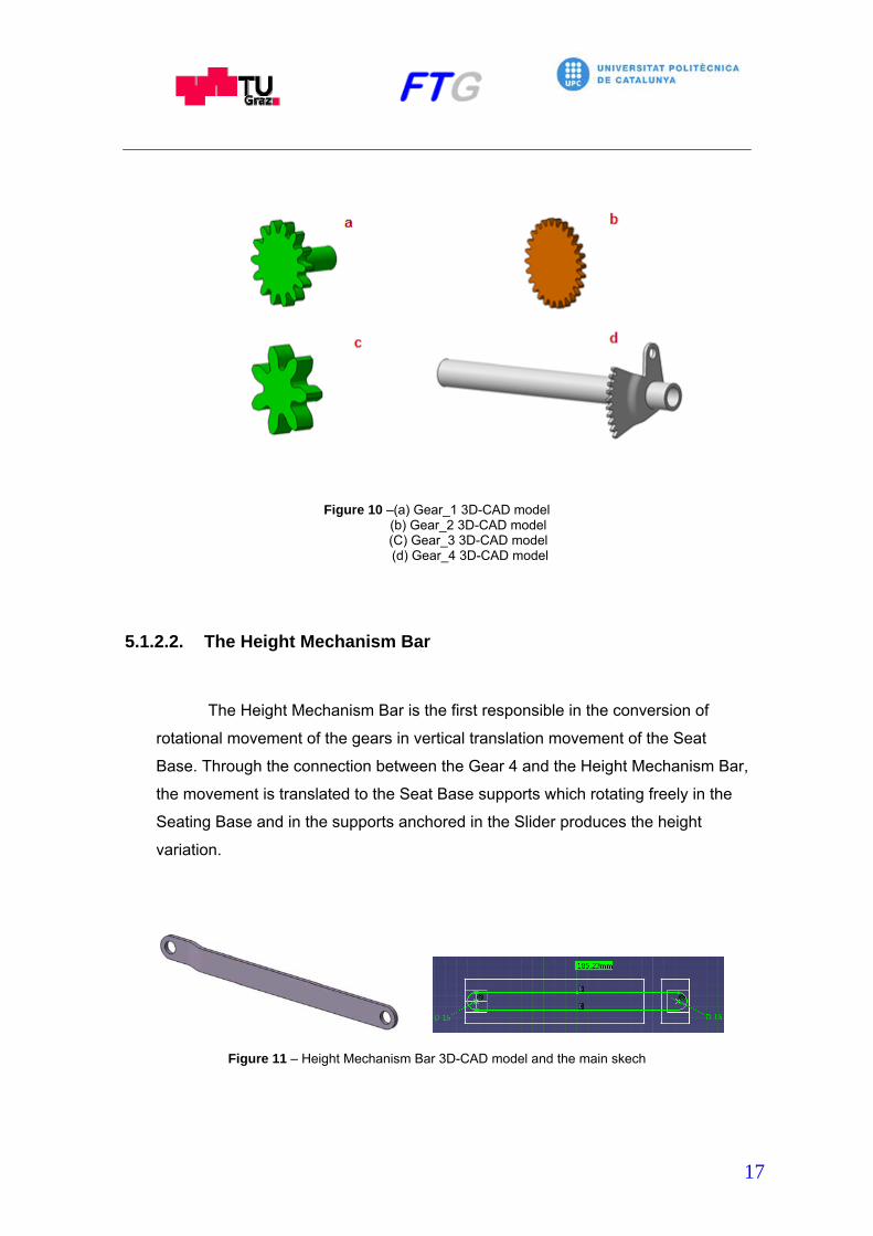
5.1.3.5. The Actuator and the Regulator
The actuator is activated for the Backrest lever axis and it is responsible to
keep and fix the Regulator with the teeth of the Backrest Mechanism Base 1.
The Regulator is moved directly by the Backrest Lever because they are
connected to each other.
On the other hand, they are located between the Backrest Mechanism
Base 1 and 2.
24
Figure 20 – (a)+(b) Different views of the regulator 3D-CAD model (c) Regulator 3D-CAD model
5.1.3.6. The Backrest
The Backrest is the main part in this mechanism and one of the most
important of the seat due to changing the backrest angle modifies the seat
geometry.
Usually it is composed of an inverted U-shaped frame with two side arms
having enough internal space for locating a plurality of flexible vertically disposed
parallel strips fixed from the upper to the lower part of the frame. The strips have
generally S-shaped configuration with a lower convex curve for supporting the
lumbar region of the back and upper concave curve for supporting the upper dorsal
region.

25
All the parts in this mechanism are designed to be able to change the
angle of this part. Also, it is the part in which is located the cushions to be more
confortable to the driver.
Figure 21 – Backrest 3D-CAD model and the main sketch
5.1.4. The Headrest Height Regulator Mechanism
Vehicle seats are typically provided with a headrest and it is desirable that
the position be adjustable in the vertical direction to receive the proportional user
head portion desired.
The Headrest Height Mechanism is used to adjust the headrest to the
desired position. It consists of one part, the Headrest body, and it can be moved to
up and down through two cylindrical guide holes located in the Backrest. This
mechanism usually is positioned on the top of the Backrest.

26
5.1.4.1. The Headrest
The Headrest is designed as a frame of the headrest cushion and also it
has a position shafts which are inserted in the two cylindrical guide holes to
support the Headrest. These position shafts are parallel to each other and are
assembled to the headrest frame.
Figure 22 – Headrest 3D-CAD model and the main sketch
5.2. Creating the Seat Model with CATIA-V5
In order to have as support tool in future complex designs a simple seat
CAD-model is performed. Usually, the shape complexity of the car seat it is an
obstacle at the design process. The extreme difficulty to create a kinematic
simulations and parameterizations in a final complex seat CAD-models may be a
cause of mistakes in the seat design process. So as to be as useful tool for the
designer, this thesis is focused in the kinematic simulation and the
parameterization of the complete seat model. For this reason, all the parts into this
model have been created as simple as possible.

27
5.2.1. Overview of Generative Shape Design Workbench in CATIA-V5
The CATIA-V5 Generative Shape Design Workbench is used to create
advanced shapes based on complex surfaces. There are a lot of possibilities to
reach the desired final model using combination of wireframe and surface features.
Also it is possible to combine generated models created with Generative Shape
Design workbench with features from Part Design workbench.
As a specific Generative Shape Design toolbars it is important to point out
some of them.
5.2.1.1. The Wireframe toolbar
The Wireframe toolbar allows the creation of wireframe geometry such as
points, lines and curves. As an example, features such as point, line, plane, circle,
spine, intersection, projection or parallel curve can be found in this toolbar.
Figure 23 – Wireframe toolbar
5.2.1.2. The Surface toolbar
The Surfaces toolbar allows the user to model both, simple and complex
surfaces. As an example, features such as extrude, offset, swept, fill, multi-
sections and blend can be found in this toolbar.
28
Figure 24 – Surface toolbar
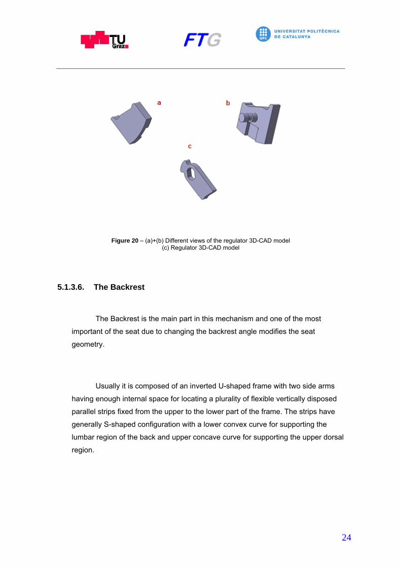
5.2.1.3. The Surface Operations toolbar
The Surface Operations toolbar allows the user to modify existing
wireframe or surfaces using features such as Join, Split, Trim, Boundaries, Edge
fillet, Translate or Extrapolate.
Figure 25 – Surface Operation toolbar
5.2.2. Creating the Parts of the Seat Model
The entire model contains thirty-five Parts and one Sub-Product. The Parts
are: the Guide Base, the Lock Base 1 and 2, the Lock, the Lever 1 and 2, the Front
Support 1 and 2, the Rear Support 1 and 2, the Seat Base, the Gear 1, the Gear 2,
the Gear 3, the Gear 4, the Height Mechanism Bar, the Backrest Mechanism Base
1 and 2, the Actuator, the Regulator, the Backrest Lever Base, the Backrest Lever,
the Backrest Lever Axis, the Cushion Base 1 and 2, the Backrest, the Headrest,
the Gear 1 Cover, the Height Mechanism Lever, the Seat Cover, the Headrest

29
Cover, the Backrest Cover, the Height Connection Bar, the Backrest Mechanism
Cover and finally the Skeleton. The Sub-Product will be the Slider and it is
composed for the Slider Left and the Slider Right.
Due to the complexity of taking measurements directly from the real piece,
the design process of the Parts has been carried out in three steps. First, it has
been taken measures related to the entire model as the complete width, the length
and the height. Secondly, in order to respect as much as possible these
measurements, has been decided which pieces of each mechanism affects directly
to these measurements if they suffer changes. Finally, these Parts have been
designed trying to respect as much as possible the measurements taken from the
real pieces and at the same time the desired measurements of the entire model.
In the next points will be explained the followed steps to build up the most
important Parts of the model.
5.2.2.1. The Guide Base
The first Part designed in this mechanism is the Guide Base. It has been
designed using the Generative Shape Design workbench of CATIA-V5. Firstly, the
sketch of the half front view shape is done and extruded
Figure 26 –Sketch + Extruded

30
Secondly, the extruded profile is transformed by symmetry.
Figure 27 – Symmetry operation
Thirdly, the Sketch of the holes on the left side is done and extruded.
Figure 28 – Sketch and Split of the holes
Finally, the hole is copied several times along its length and in the Part
Design workbench it is applied the thickness desired to its surface.

31
Figure 29 – Final surface + thin application
5.2.2.2. The Lock
The Lock has to be designed according few parameters. On the one hand,
the width between the Lock’s teeth has to be designed with the same width used
between the side holes of the guide base. Likewise, the length of the teeth has to
be enough to pass through the Locking Base and the Guide Base holes.
Otherwise, the Lock could not perform the function which is designed.
On the other hand, when the Lever is turned the Lock has to define an
enough arc to allow the movement between the Slider and the Guide Base.
Firstly, some important support points are created. In the same way, in
order to define part of the final geometry the Sketch mode is activated and some
2D sketches are carried out.

32
The picture bellows represents these first operations.
Figure 30 – Basic sketch
Secondly, some surfaces are created using features of the Surfaces tool as
Extrude, Fill, Edge Fillet and Blend. At the same time, some changes are done in
these surfaces using the Surfaces Operations tool as Split, Symmetry and Join.
The picture bellow shows the final result of applying surface operations.
.
Figure 31 – Basic Surfaces

33
Finally, some changes and the thickness have to be applied. For this
reason, it is necessary to change to Part Design workbench. Using tools as
Thickness and edge Fillet is achieved the final shape of the Lock.
Figure 32 – Final application of thin
5.2.2.3. The Gears
Gears are quite complex machine elements and understanding them is
quite difficult. Before explain the steps followed in the gear design with CATIA, one
must be aware of what type of gear is going to be designed and which basic
parameters are needed in order to design the elaborated aspects of them.
The table below shows the standards parameters and general formulas
used to define the spur gear’s geometry.
Parameter Unit Formula Description
A angle 20deg Pressure angle:
( 10deg ≤ a ≤ 20deg ) M mm - Module
Z integer - Number of teeth ( 5 ≤ Z ≤ 200 )
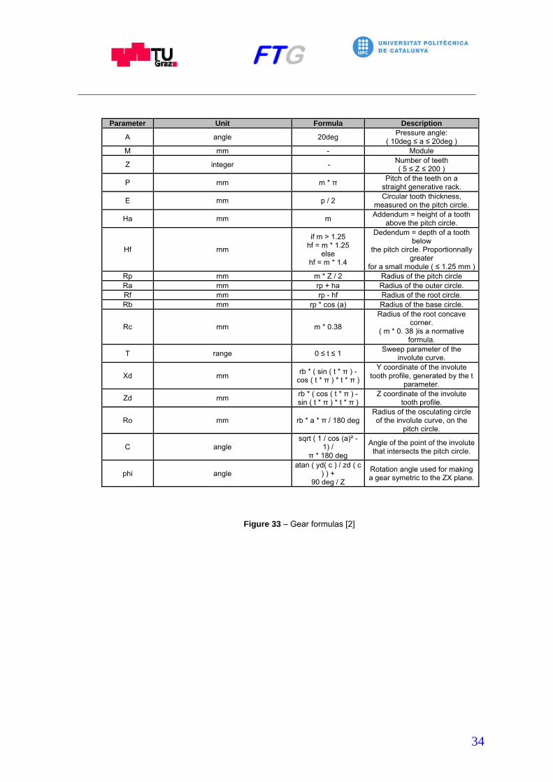
34
Parameter Unit Formula Description
A angle 20deg Pressure angle:
( 10deg ≤ a ≤ 20deg ) M mm - Module
Z integer - Number of teeth ( 5 ≤ Z ≤ 200 )
P mm m * π Pitch of the teeth on a
straight generative rack.
E mm p / 2 Circular tooth thickness,
measured on the pitch circle.
Ha mm m Addendum = height of a tooth
above the pitch circle.
Hf mm
if m > 1.25 hf = m * 1.25
else hf = m * 1.4
Dedendum = depth of a tooth below
the pitch circle. Proportionnally greater
for a small module ( ≤ 1.25 mm )Rp mm m * Z / 2 Radius of the pitch circle Ra mm rp + ha Radius of the outer circle. Rf mm rp - hf Radius of the root circle. Rb mm rp * cos (a) Radius of the base circle.
Rc mm m * 0.38
Radius of the root concave corner.
( m * 0. 38 )is a normative formula.
T range 0 ≤ t ≤ 1 Sweep parameter of the
involute curve.
Xd mm rb * ( sin ( t * π ) -
cos ( t * π ) * t * π )
Y coordinate of the involute tooth profile, generated by the t
parameter.
Zd mm rb * ( cos ( t * π ) - sin ( t * π ) * t * π )
Z coordinate of the involute tooth profile.
Ro mm rb * a * π / 180 deg Radius of the osculating circleof the involute curve, on the
pitch circle.
C angle sqrt ( 1 / cos (a)² -
1) / π * 180 deg
Angle of the point of the involutethat intersects the pitch circle.
phi angle atan ( yd( c ) / zd ( c
) ) + 90 deg / Z
Rotation angle used for making a gear symetric to the ZX plane.
Figure 33 – Gear formulas [2]

35
Figure 34 – Gear Sketch [3]
According to the table above and due to most of geometric characteristics
are related to each other, it is possible to design a gear using a few parameters,
and also they can be controlled by the followed parameters:
The module: M
The pressure angle: A
The number of teeth: Z
Then it is possible to start to create and edit parameters using the feature
Formula, which is located in the menu Tools/ Knowledge, in the Generative
Surface Design workbench of CATIA.

36
Figure 35 – Knowledge toolbar
At the beginning, the unit is selected and the create parameter button
activated. The next step is to create a new parameter name and set the initial
value if the parameter has a fixed value. On the contrary, the formula editor allows
the parameter to be defined with a formula. Accordingly, using the table on the
Fig.31 now the parameters a, m, Z, rp, ra, rb, rf and rc can be defined.
Figure 36 – Edit window of parameters

37
Figure 37 – Formula Editor window
Now, the formula of the Cartesian position of the points of the involute
curve of a tooth has to be defined using the Parametric Laws tool.
Figure 38 – Law editor window

38
In order to define the first tooth of the whole gear, 5 points have to be
created. Each point will have the x and z coordinates according to the previously
defined xd and zd coordinates and the t parameter from t=0 to t=0.4.
Figure 39 – Example of definition of one of the five points
When the points have been created should be generated a Spine through
these points. Afterwards, the Spine curve has to be extrapolated for joining it with
the root circle. The result of these operations is rotated from the Y axis as a
reference by the c angle, previously created as parameter.
The figure bellow represents this process [2].
Figure 40 – Construction Example

39
At this point, two circles have to be created with the ra and rf parameters as
a radius of each one. In addition, the rounder corner between the root circle and
the extrapolated involute curve can be created using the rc parameter. This rc
parameter will define the radius of this corner. Then, the intersections between the
involute curve and the circle can be cut using the function split. The result of these
operations can be transformed using the tool symmetry by the ZY plane.
Figure 41 – Definition of the first tooth
Now, it has to be designed the symmetry plane between each tooth. The
rotation angle of the ZY plane around the Y axis depends on the number of teeth
and it is defined by the next formula:
Symmetry Plane Rotation Angle = 180º / Z [2]
When the plane has been created, the root circle can be cut with it. Next,
using the Circular Pattern tool, can be defined the instances will be repeated this
tooth around 360º. For this reason, has to be created a formula which makes a
relation between the number of instances and the Z parameter.
Finally, the first tooth and the duplicated teeth are joined using the Join tool
and the resulting profile can be extruded with the desired thickness.

40
Figure 42 – Application and result of circle pattern
Figure 43 – Finished gear

41
5.3. The Assembly of the Parts
Once all Parts of the model have been created, the assembly of them can
be performed. Using the Assembly Design Workbench is possible to bring together
Parts, Products or sub-Products into an assembly as a CATProduct. CATProducts
also can be composed of smaller CATProducts to carry out bigger assemblies. In
addition, it is possible to use them in Kinematic Simulations converting the
constraints used in the assembly design creation process [4].
So as to have a better idea of the most important features of Assembly
Design, they are going to be explained in the next point.
5.3.1. Overview of Assembly Design Workbench of CATIA-V5
Before starting to explain the features of this workbench, it is necessary to
take a look to the different nodes present in the CATProduct Specification Tree.
The most commonly used are the Product, the Part and the Component as is
shown in the picture bellow. They can be added to the Specification Tree through
the Product Structure Tools toolbar.
Figure 44 – Different nodes found in the specification tree of the assembly
To maintain the position of the Products, Parts or sub-assemblies within the
CAT-Product, Assembly Constraints are used. When a constraint is defined, it is

42
attached to the Specification Tree under the Constraints Node. In order to create
new constraints between elements inside the CAT-Product, the Assembly
Constraints toolbar is used.
.
Figure 45 – Constraints toolbar
The table below describes the function of each one of the features found in
the Assembly Constraints toolbar.
Figure 46 – Table of types of constraints [5]

43
After the assembly of the desired Parts, the Space Analysis toolbar offers
the possibility of make analysis using the Clash Analysis feature. Once the Clash
Analysis is selected, the control panel of the feature allows you specify the type of
check and where is going to be performed.
Figure 47 – Space Analysis toolbar and definition window of Clash Analysis
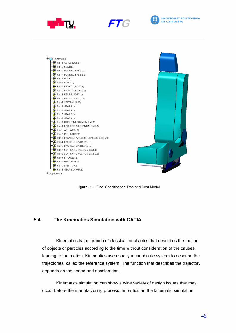
5.3.2. Creating the Assembly of the Parts
The assembly has to be created with all the components previously
explained in the point 5.1 “Important Parts into the model”. In that case, in order to
make the model more stable, all the Parts have been designed according to the
final position. For that reason, Fix constraints have been attached to all the
components in order to maintain the position. The resulting Specification Tree, the
mechanisms and the complete seat after the assembly are shown in the picture
bellow.
44
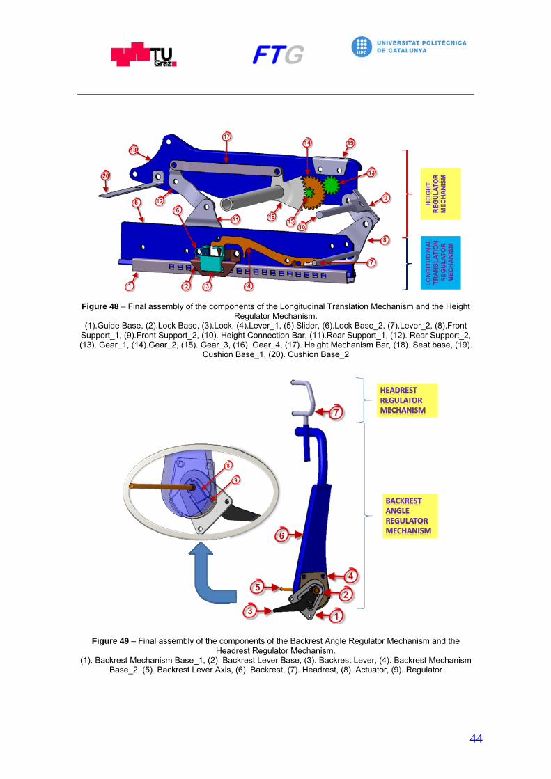
Figure 48 – Final assembly of the components of the Longitudinal Translation Mechanism and the Height
Regulator Mechanism. (1).Guide Base, (2).Lock Base, (3).Lock, (4).Lever_1, (5).Slider, (6).Lock Base_2, (7).Lever_2, (8).Front
Support_1, (9).Front Support_2, (10). Height Connection Bar, (11).Rear Support_1, (12). Rear Support_2, (13). Gear_1, (14).Gear_2, (15). Gear_3, (16). Gear_4, (17). Height Mechanism Bar, (18). Seat base, (19).
Cushion Base_1, (20). Cushion Base_2
Figure 49 – Final assembly of the components of the Backrest Angle Regulator Mechanism and the Headrest Regulator Mechanism.
(1). Backrest Mechanism Base_1, (2). Backrest Lever Base, (3). Backrest Lever, (4). Backrest Mechanism Base_2, (5). Backrest Lever Axis, (6). Backrest, (7). Headrest, (8). Actuator, (9). Regulator
45
Figure 50 – Final Specification Tree and Seat Model
5.4. The Kinematics Simulation with CATIA
Kinematics is the branch of classical mechanics that describes the motion
of objects or particles according to the time without consideration of the causes
leading to the motion. Kinematics use usually a coordinate system to describe the
trajectories, called the reference system. The function that describes the trajectory
depends on the speed and acceleration.
Kinematics simulation can show a wide variety of design issues that may
occur before the manufacturing process. In particular, the kinematic simulation

46
allows analysis of the relative movement between two parts, to detect possible
interferences or calculate velocities and accelerations.
For that purpose, it is possible to put the Assembly into motion using DMU
Kinematics Workbench of CATIA-V5.
5.4.1. Overview of DMU Kinematics Workbench of CATIA-V5
The DMU Kinematics Workbench is a separated design module which is
dedicated to simulate the Assembly movements. Using this workbench, it is
possible to define kinematics mechanisms, simulate movement mechanisms and
to detect collisions.
Next, some of the most important terms used in this Workbench will be
explained.
5.4.1.1. The Kinematics Mechanism
Kinematics mechanism is a series of rigid elements connected with joints to
form a closed chain, or a series of closed chains. Each element has two or more
joints, and the Joints have various degrees of freedom to allow the motion between
the links. The kinematics mechanism is usually used to convert or transmit the
movement. Every mechanism has a Fixed Part through the movement occurs.

47
5.4.1.2. The Degrees of Freedom
An isolated body that moves freely in the three dimensional space has
three independent rotations and three translation displacements according to a
fixed axis which defines the three directions of a base referred to a three
dimensional space. For instance, a piece on a plane can be moved in vertical and
horizontal and any other translation is a result of these two components. Also, it
can rotate on itself. Therefore, if this piece has not any restriction it will have three
degrees of freedom.
In that case, in order to define the degrees of freedom of the two
dimensional mechanism, it can be calculated through the Grübler-Kutzbach
equation.
m = 3 ( n – 1 ) – 2j1 – j2 [6]
Where: m= mobility
n= number of elements of the mechanism
j1= number of one degree of freedom joints
j2= number of two degree of freedom joints
5.4.1.3. The Joints
The unions between two members of a mechanism which can move with
respect to each other are connected together through kinematic joints. This union
creates a Kinematic Pair and the properties of joints between them such as the
relative motion and degrees of freedom determine the resultant motion of a
mechanism. For this reason, the joints are one of the most important parts of a
mechanism.

48
The kinematic Joints can be classified into two categories based on the
type of contact between them as Lower Pairs or Higher Pair. Likewise, when the
connections are reduced to simple forms of construction, the Lower Pairs are
divided into six types of connections. The foregoing six types of connections are
shown in the picture bellow. The common denominator of these connections
appears to be the area contact between links.
Figure 51 – Types of Joints [7]
In the Higher Pairs connections the contact between the two members is a
point or line geometry. Point contact is found in ball bearings and the line contact is
characteristic of cams, roller bearings and most gears. Higher Pairs connections
on occasions can be replaced by a combination of Lower Pairs.
DMU-Kinematics Workbench of CATIA-V5 offers sixteen different joint
types. These joints and their characteristics are shown in the picture below.

49
Figure 52 – Types of Joints found in the DMU Kinematics workbench [8]
5.4.1.4. The Commands
The commands are angular or linear values which define the kinematics
motion. So as to define commands into the mechanism, it is important to think

50
about which Part will drive the mechanism. For instance, the gear drives the pinion
by the belt in the case of a bike.
In order to define a command in DMU Kinematics Simulation, a Joint has to
be created before. Going inside the Joint properties and defining the option Angle
Driven or Length the command is created. Even so, there are Joints that do not
allow add commands.
5.4.2. Creating the Kinematic of the Mechanism
The previous step before starting to translate the kinematic of the real
model to the 3D-CAD model is to study its functionalities. The real model has four
functionalities as is shown in the picture below.
Figure 53 – Functionalities of the seat.

51
When the assembly is done, the first step to perform the kinematics
simulation in the 3D-CAD model is to fix a Part using the Fix feature from the DMU
Kinematics Toolbar. After clicking the Fix feature but before defining the Fixed
Part, it will appear another pop up box which allows you to create a new
mechanism. Once the mechanism is created it can be defined the fixed Part. In
that case, the fixed Part will be the Guide Base.
Figure 54 – New Mechanism window and DMU kinematics tool bar with Fix Part feature selected.
Then, Joints can start to be created. Opening the Kinematic Joints toolbars
it is possible to select the desired joint. First, the forward and backward motion of
the seat will be defined. For that purpose, a Prismatic Joint will be created between
the Slider and the Guide Base.
Figure 55 – Kinematics Joints toolbar with Prismatic Joint selected

52
This motion must be defined with a certain range. For this reason, the
Length Driven box is activated. This allows you to change the limits. According to
CATIA-V5 terminology, specifying some Joints as Angle or Length driven joint is
synonymous to defining a Command. This is observed by the creation of
Command.1 line in the tree.
Figure 56 – Specification Tree and Prismatic Joint editor window
Next, the movement of the lever between the slider has to be defined.
Turning the lever allows the foregoing movement and it has to be defined with a
Revolute Joint. This motion must be defined with a certain range. At the same
time, the movement between the Lock and the Lock Base it is created. Also, it is
defined with a Revolute Joint. In order to combine the two rotational movements, a
Point Surface Joint will be created between them. Using this joint, the rotational
movement of the Lock between the Lock Base will be activated through the
rotational movement of the Lever between the Slider. Now, a new command can
be observed in the tree.

53
Figure 57 – Specification tree
Figure 58 – Motions of the Longitudinal Translation Mechanism. The involved Parts are: (1) Lever_2, (2) Lever_1, (3) Slider, (4) Lock, (5) Lock Base, (6) Guide Base
Afterwards, in order to define the related movement between Parts when
the Height Regulator Mechanism is activated, several Revolute Joints must be
created. This joint will be established to the Gear 1, the Gear 2 and the Gear 4
between the Seat Base. Also, it will be established to the Front Support 1 and 2
between each other and the Front Support 2 between the Seat Base. In the same
way, it will be established to the Rear Support 1 and 2 between each other and the
Rear Support 2 to the Seating Base. Finally, it will be carried out between the
Height Mechanism Bar and the Gear 4 and the Rear Support 2.

54
The next step is to define the movement between gears. This is achieved
creating Cylindrical Joints. Also, it is necessary to determine which Part will
command the mechanism. For this reason, an angle driven will be added to the
Gear 1. Then, the Cylindrical Joint will be established between the Gear 1 and the
Gear 2 and between the Gear 2 and the Gear 4. The picture bellow shows how the
tree is created.
Figure 59 – Specification Tree
Figure 60 – Motions of the Height Regulator Mechanism. The involved Parts are: (1) Gear_1, (2) Gear_2, (3) Gear_3, (4) Gear_4, (5) Height Mechanism Bar, (6)
Rear Support_2, (7) Rear Support_1, (8) Front Support_2, (9) Front Support_1, (10) Seat Base

55
The motion of the Backrest Lever between the Backrest Mechanism Base
is defined using a Revolute Joint. The movement of the Backrest Lever
determinates the rest of Parts involved in this mechanism. Accordingly, an angle
driven is defined. To describe the Regulator movement between the Backrest
Mechanism Base, which is made by the Backrest Lever, a Prismatic Joint is
created. Afterwards, a Point Curve Joint will be created in order to combine these
two movements. Thus, a new command is added in the tree.
Once finished the precedent command, the last two movements between
Parts of the model are created quickly. These movements are the variation of the
Backrest Angle and the Headrest Height Regulator. In order to define the Backrest
Angle, a Revolute Joint between the Backrest Angle Mechanism Base 1 and 2 are
created whereas the movement between the Headrest and the Backrest are
carried out using the Prismatic Joint.
Finally, to reduce the Degrees of Freedom of the mechanism several Rigid
Joints are added to different Parts of the model. As a result, the expansion tree
should be looks like the picture bellow.

56
Figure 61 – Final Specification tree

57
5.4.2.1. Simulating the Mechanisms
When the DOF are zero the mechanism can be simulated. However,
CATIA offers many options to carry out this aim. In that case, the mechanism is
going to be simulated with commands and afterwards a record of the simulation is
done.
Figure 62 – Followed Steps in the Kinematics design
5.5. The Parameterization with CATIA
Design changes are commonly found in the product development process.
When a product is being developed, a geometric change in one of its components
can entail modifications in the rest of the product components. Consequently,

58
affects the entire product assembly. Nowadays, new CAD software packages offer
many possibilities to solve this problem as the parametric-associative design.
Using the Formula feature of CATIA, it is possible to create parameters and
relations between components in order to define the geometry of a Part or a
Product carrying out a new cycle of design.
5.5.1. Creating the Parameterized Model
There are many strategies to define parameterized models. On the one
hand, it is possible to create parameters within a component related to an internal
dimensional constraint. Then, this dimension will change simply modifying the
parameter value inside the Part. If the parameterization has to be carried out in
single components maybe it is the best strategy. On the other hand, it does not
very useful when the parameterization has to be carried out on an assembly of
several components or sub-assemblies. Then, creating parameters on the
assembly and making relations between them and constraints, positions and
parameters inside Parts, the geometry of the entire model can be controlled. One
accurate way is to create several reference points, lines or planes in order to
define the structure and the most important points of the model in a new Part
inside the assembly commonly called Skeleton. These reference elements will
control the position of the Parts in the space or geometrical constraints of a single
or multiple Parts. For that purpose, the position of these elements inside the
Skeleton is controlled creating parameters related to them in the assembly and
afterwards, relations between them and parameters, geometrical constraints or
reference points inside Parts have to be carried out. Using this method, the control
of all geometrical characteristics of the Parts can be executed only changing the
position of the Skeleton reference elements. In that case, due to the model is
composed for several Parts it was the followed strategy.

59
Figure 63 – Parameterization Strategy
In this thesis, in order to have a model as versatile as possible, three
parameters will define the geometry of the entire model: the Width, the Length, and
the Height whereas four parameters will define geometry of single Parts on the
assembly level: the Backrest Height, the Backrest Angle, the Headrest Height and
the Headrest Width. All of them have been created related to the body of the seat.
Modifying these parameters it is possible to adjust the seat model to the desired
space or geometry.

60
Figure 64 – Parameters created in the assembly
The next points have been created so as to explain the points created in
the Skeleton Part and all the characteristics related to the parameters.
5.5.1.1. The Skeleton
The Skeleton is composed of seven points. The Parameterized_1 point is
created to define the reference point for all of them. It is located in the default
origin point of CATIA, it means it is on the (X=0, Y=0, Z=0) of the coordinate
system. The Parameterized_2 point Y coordinate value is controlled by the Width
parameter. Then, will define the distance in the Y axis between the
Parameterized_1 point and itself. The Parameterized_3 point X and Y coordinate
values are controlled by the Length and the Width parameter respectively.
Consequently, it defines the distance between the Parameterized_1 and the
Parameterized_3 points in the X and Y axis. In the same way the Parameterized_4
point Y and Z coordinate values are controlled by the Width and the Height
parameter respectively. Therefore, it defines the distance between the
Parameterized_1 and the Parameterized_4 points in the Y and Z axis. Likewise,
the Parameterized_5 point X, Y and Z is controlled by the Length, the Width and
the Height parameters respectively. In other words, the distance between the
Parameterized_1 and the Parameterized_5 points is defined in the three axis of

61
the coordinate system. Basically, these points have been created in order to define
the position of the reference point of each component of the model although in
some cases have reference on some geometrical constraints.
While the previously mentioned points position are related directly with the
Parameterized_1 point, the Parameterized_6 point is related with the
Parameterized_5 point and the last one with the Parameterized_7 point. The
Parameterized_7 point defines the top of the Backrest and the Parameterized_6
point the vertical distance between the Parameterized_7 point and the reference
point of the Backrest Part. The reason is that these two points have a specific
function inside the model. The Parameterized_6 and the Parameterized_7 points
are the responsible to define several characteristics of the Backrest, the Backrest
Cover, the Headrest and the Headrest Cover.
Figure 65 – Points of the Skeleton in the Specification Tree and in the space

62
5.5.1.2. The Width parameter
This parameter is related to the distance between the center line of the seat
and the center line of the Guide Base according to the Y axis although at the same
time, it has effect on the entire model. In other words, modifying the Width
parameter is possible to adjust the seat to the desired width. As a result, the Parts
with elements located on the Y axis will be modified according to the input value.
It has been created with a specific range but it can be modified in order to satisfy
the needs of the designer. This range comprises the values between 125 and 250
mm each included. By contrast, the seat development process can be focused first
on the measurements of the cushion. In this model, the distance between the
center line of the Guide Base and the exterior surface of the cushion is 36 mm. For
instance, if the desired width of the cushion must be 500 mm then, the input value
of this parameter will be 214 mm.
Figure 66 – Width Parameter on the assembly level
5.5.1.3. The Length parameter
This parameter defines the length of the Guide Base according to the X
axis. When the input value of this parameter is changed some Parts located on the
X axis will suffer changes on its geometry. These Parts are the Guide Base, the
Seat Base and the Height Mechanism Bar which increases or reduces its length.
Also, the Length Parameter has been designed with a specific range comprised
from 385 to 450 mm each included. In the same way, as the Width parameter the
seat development process can be focused on other measurements in order to

63
define the length. As reference, the difference between the reference measure of
this model and the rotation axis of the Backrest Part is to rounding off 31 mm.
Figure 67 – Lenght Parameter on the assembly level
5.5.1.4. The Height parameter
This parameter controls the height between the floor of the car and the
Seat Base according to the height of the Slider. In fact, it has only geometrical
relation in the height of the Slider but all the remaining Parts of the model will be
modified its position in the space. In the same way, it has been defined with a
certain range from 78 to 150 mm each included. If the needs of the designer are to
know the distance between the Seat base and the floor the difference between the
input value and the top of the Seat Base is always 114 mm.
Figure 68 – Height Parameter on the assembly level
5.5.1.5. The Backrest Height parameter
This parameter controls the height of the Backrest and the Backrest Cover
Part according to the vertical distance between the center axis of the pipe which
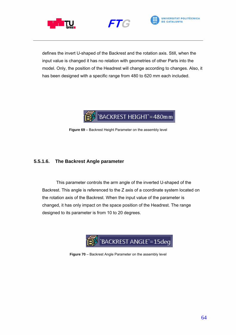
64
defines the invert U-shaped of the Backrest and the rotation axis. Still, when the
input value is changed it has no relation with geometries of other Parts into the
model. Only, the position of the Headrest will change according to changes. Also, it
has been designed with a specific range from 480 to 620 mm each included.
Figure 69 – Backrest Height Parameter on the assembly level
5.5.1.6. The Backrest Angle parameter
This parameter controls the arm angle of the inverted U-shaped of the
Backrest. This angle is referenced to the Z axis of a coordinate system located on
the rotation axis of the Backrest. When the input value of the parameter is
changed, it has only impact on the space position of the Headrest. The range
designed to its parameter is from 10 to 20 degrees.
Figure 70 – Backrest Angle Parameter on the assembly level

65
5.5.1.7. The Headrest Height parameter
The Headrest Height parameter controls the distance between the axis of
the lower cylinder that forms the body of the Headrest and the top of the cushion.
This parameter it has no impact in the position of any Part of the seat model, only
in the geometry of the Headrest Cover geometry and the Headrest. The range of
this parameter is comprised from 120 to 220 mm.
Figure 71 – Headrest Height Parameter on the assembly level
5.5.1.8. The Headrest Width parameter
The Headrest Width parameter controls the distance between the center
line of the seat and the side of the inferior side of the Headrest Cover. This
parameter has no impact on the position or the geometry of any Part of the seat
model, only on the geometry of the Headrest Cover and the Headrest. The range
of this parameter is comprised from 140 to 220 mm.
Figure 72 – Headrest Width Parameter on the assembly level

66
6. Conclusions
This Thesis includes the creation of a 3D-CAD model based on an existing
real car seat. Detected a certain problem in the development of this type of
products, this work has been focused specially in a detailed study of the
kinematics of the seat functionalities. At the same time, it was important to be
specific about the parameters which define the geometry of the single components
or the entire model of the seat. The design of the seat kinematics and the
parameters should be useful tool to implement the model in future development
processes. So as to achieve the objectives of this Thesis, it was chosen to create
the model with CATIA-V5 R16 version and the Generative Shape Design
workbench and try to simplify the complex shapes found in the seat as a method.
Studying all the components of the seat and their functionalities individually and
regarding the influence on the entire model, the kinematics of the seat has been
carried out. That involves the creation of several mechanisms on the 3D-CAD
model and the possibility of changing the values that are defining them. Then the
model can be useful to analyze opportunities to improve these kinematics
mechanisms or the geometry of components using the model as a base to the
study. On the other hand, due to the different application fields in which the model
can be implicated, the external control of the geometry of the entire model or some
components must be carried out. For this reason, parameters or relations in a
single part or regarding to the entire model were implemented on the assembly
level. The strategy followed was the creation of a new Part in which several
elements were defined and related to the already existing reference points of the
components previously created. Also, the parameters are related to the elements
of the mentioned new part. It allows the designer to put new input values and
consequently to change components geometries, positions, etc.

67
6.1. Further overview of possible studies
The scope of this thesis was to obtain a reliable and useful tool to improve
the development process of automotive seat, but the main problem found was that
there was not enough available information. But as a first and very important step
a good kinematic model was created. Also it is possible to vary the motions making
little changes in the geometry of some components.
Based on this thesis further studies could be made. The first step that could
be performed is the definition of the construct parameters of the seat under laws in
order to give a clear idea of which measurements are controlling changing the
input values of the parameters. This point could be extended widely inserting
standards procedures to the first steps of the seat design.
In the same way, a lot of improved or different mechanisms can be added
to the seat model and study their results and the differences between them.

68
7. Bibliography
Brass, Egbert (2005): Konstruieren mit CATIA V5. HANSER.
Burke, Kevin. (2003): AIRBUS Foundation Course. Assembly Design. Available in
Internet at: http://www.scribd.com/doc/7199582/Catia-v5-Assembly-Design [4]
CATIA V5 R16-DMU Kinematics Simulator User’s Guide. Available in Internet at:
http://www.scribd.com/doc/8230874/Catia-V5-R16DMU-Kinematics [8]
Cozzeus, Richard. n.d: CATIA V5 Workbook Release 5. SDC Publications.
Southern Utah University.
Denavit, Jacques; Hartenberg, Richard; (1964): Kinematic synthesis of linkages.
Department of Mechanical Engineering and Astronomical Sciences. Northwestern
University. [7]
Hirtz, Mario; Göber, Tanja; Lang, Michael. (2010): CATIA V5 Surface Design. Graz
University of Technology. Institute of Automotive Engineering. Member of the Frank
Stronach Institute.
Lang, Michael; Macheiner, Harald. (2008): CATIA V5 Basic Training. Cax In
Automotive and Engine Technology. Graz University of Technology. [5]
Meeth, Jan; Schuth, Michael (2006): Bewegungssimulation mit CATIA V5.
HANSER.
Gear Theory Manual. Available in Internet at:
http://www.bostongear.com/pdf/gear_theory.pdf [3]
Trébaol, Gildas. (2005): Designing Parametric Spur Gears with Catia V5. Available
at Internet at: http://gtrebaol.free.fr/doc/catia/spur_gear.html [2]
Catia home page. Available in Internet at: http://www.3ds.com/products/catia [1]
Cardona, Salvador. (2001): Teoría de Máquinas. Edicions UPC [6]

69

70