Embed Size (px)
Citation preview
Dipl.-Ing. Stefan Vogt Zentrum Geotechnik, Technische Universität München
Buckling of slender piles in soft soils –
Large scale loading tests and introduction of a simple calculation scheme

Research work at the Zentrum GeotechnikMotivation
load
firm soil layer
slender piles
foundation
weicheBodenschicht(very) soft soil layer
Has buckling to be expected ?

Are the standards requirements save enough?
EC 7:„.. check for buckling is not required if cu exceeds 10 kPa..“
Other codes set this limit of undrained shear strength at 15 kPa or 10 kPa(eg. DIN 1054, 2005 or the national technical approvals for micropiles)
Research work at the Zentrum GeotechnikMotivation
We asked:
Are the published design methods capable to simulate the interaction between the supporting soil and the pile?
Research work at the Zentrum GeotechnikMotivation
Reviewed papers:
Vik (1962), Wenz (1972), Prakash (1987), Wennerstrand&Fredriksson (1988), Meek (1996), Wimmer (2004), Heelis&Pavlovic&West (2004)
We asked:

2.) An elastic approach to describe the lateral soil support is not appropriate
Summary of the results obtained in the first step
1.) The standards rules underestimate the possibility of pile buckling
3.) Most published calculation methods cannot simulate the pile‘s behavior properly
Literature research
In situ field load test
Model scaled tests
Large scaled loading tests
Development of a simple design method
Development of a numerical FE-Model Reported by Prof. N. Vogt at the IWM 2004 in Tokyo
Research work at the Zentrum GeotechnikIntroduction

Aim:
Proofing the obtained expertise with large scaled loading tests on single piles
Development of a simple design method that can simulate the main effects recognized in the loading tests
Literature research
In situ field load test
Model scaled tests
Large scaled loading tests
Development of a simple design method
Development of a numerical FE-Model
Research work at the Zentrum GeotechnikIntroduction

Large scaled loading testsLoading of 4 m long single piles
Container made up with concrete segments
Pile is pinned top and bottom

axial loading forcesettlement of
the pile head
1,0 m
1,0 m
1,0 m
1,0 m
lateral deflection
lateraldeflection
lateraldeflection
4,0 m
Measuring devices
Large scaled loading testsLoading of 4 m long single piles
Container made up with concrete segments

Mixing up the soil in a liquid consistency
Filling the containers by pumping the liquid soil – following consolidation with the help of the electro osmotic effects
Draining system
Pumping the liquid soil
Large scaled loading tests
necessary settlement
bridge abutment
hydraulicjack
test pile
rigid foundation
geotextiledrainage
surchargeload
necessary settlement
bridge abutment
hydraulicjack
test pile
rigid foundation
geotextiledrainage
surchargeload

Pile type I:Composite cross section GEWI28Steel rod d = 28 mm Hardened cement slurry D = 100 mm
Pile type II:Aluminum profileThickness = 40 mmWidth = 100 mm
Large scaled loading tests

Large scaled loading tests
Exemplary illustration of a loading test:
Alu-pile surrounded by a supporting soil of cu = 18 kPa

Statistical analysis:
maximum shear strength
residual shear strength
Large scaled loading testsShear vane tests: Soil support of cu = 18 kPa
Maximum shear resistance cfv
= 18,7 kN/m2
= 2,1 KN/m2Mean valueStandard deviation
Residual shear strength cRv
= 12,7 kN/m2
= 1,2 KN/m2Mean valueStandard deveation
Normal plastic clay TMw = 40,8..42,1 %Ic = 0,53..0,48
0 10 20 30 40undrained shear strength cu [kPa]

0
25
50
75
100
125
150
175
200
225
250
0 600 1200 1800 2400 3000 3600 4200 4800 5400 6000 6600 7200 7800 8400 9000
Meßdauer [s]
Pfah
lnor
mal
kraf
t N [k
N]
0
4
8
12
16
20
Vers
chie
bung
am
Pfa
hlko
pf u
O [m
m]
Pfahlnormalkraft
Verschiebung uo
Querschnitt:
Versuchsnummer: KFL-FLACH40x100-02 System:
uO
N
A
Large scaled loading testsLoading characteristic: Soil support of cu = 18 kPa
Settlement of the pile head
Sudden increase of the pile head settlement while the axial normal force is decreasing
time [s]
settl
emen
t of t
he p
ile h
ead
[mm
]
axia
l pile
forc
e [k
N]
No sign in the characteristic of the measured deformations that showed the pile failure in advance!

Large scaled loading testsLateral deflection: Soil support of cu = 18 kPa
Axial force N deflection w
N
220 kN (ultimate) 9 mm
212 kN 1,2 mm
100 kN 0,9 mm
50 kN 0,4 mm
ww

Large scaled loading testsAnalysis
Results:
- With an increasing soil’s undrained shear strength cuthe ultimate bearing capacity rises
0
50
100
150
200
250
300
350
400
450
500
0 5 10 15 20 25cu [kN/m2]
N [k
N]
pile type I (Ep·Ip = 55 kNm2)
pile type II (Ep·Ip = 38 kNm2)
600plastic normal force pile type II
plastic normal force pile type I- Buckling regularly determined the ultimate state of the system, even in soils with an undrained shear strength of cu > 15 kN/m2

0,0
200,0
400,0
600,0
800,0
1000,0
0,00 2,00 4,00 6,00M [kNm]
N [k
N]
cu = 0 kN/m2
cu = 10,5 kN/m2
cu = 18,7 kN/m2
Interaktionskurve des Pfahles FLACH40x100
Large scaled loading testsAnalysis
Results:
No failure due to a limited pile‘s material strength!
maximum interaction of the internal force variables (pile type II)
??Even the backing moment
out of the lateral soil support is not considered

Large scaled loading testsAnalysis
For lower axial forces the lateral deflections of the pile remain very little (stiff behavior)
The failure of the micro piles occurred suddenly (no sign of failure from the measured deformations)
The halve waves of the buckling pile‘s bending curve were always smaller than the full pile‘s length (from joint to joint)
Results:

Introduction of a simple design method

Substituted mechanical system with a buckling length of LHw
an infinite long pile can be assumed for the calculations;
N
z
the length of the effective buckling figure’s half wave LHw can develop freely for the most conditions in situ at the upper and lower boundaries of the soft soil layer
LHw
Introduction of a simple design methodFinding a static system
the large scaled loading tests showed that the length of the buckling figure’s half waves were smaller than the maximum possible length of 4 m;

All forces acting on the static system with a length of LHw
z
LHwLHwp(z)
P
zp
Lateral soil support
w0,M
N
N
wN,M
MM
Bending moment in the middle
T = P
T = 0
Introduction of a simple design methodFinding a static system

Setting up equilibrium:
z
LHwLHwp(z)
P
zp
w0,M
N
N
wN,M
MM
T = P
T = 0
Condition ∑M = 0 at the pinned top
pHw
M,NM zPimpLwNM ⋅−
+⋅=
Introduction of a simple design methodDerivation
Force from the lateral soil support is defined piecewise in order to a elastic-plastic soil resistance

z
LHwLHwp(z)
P
zp
w0,M
N
N
wN,M
MM
T = P
T = 0
Force P from a bi-linear approach of the supporting soil:
π⋅⋅= Hw
M,NlLwkP for: wN,M < wki
deformation wN,M
supportion force P
wki
kl
1
Introduction of a simple design methodDerivation
for: wN,M ≥ wkiπ⋅⋅= Hw
kilLwkP
pffor a deformation of wN,M > wkithe lateral supporting force is remaining constant

Condition ∑M = 0 at the pinned top
pHw
M,NM zPimpLwNM ⋅−
+⋅= ″⋅⋅−= M,NppM wIEM
Assumption: The pile‘s material remains elastic
impLw
Lp1IEL
wN
HwM,N
2HwM2pp2
Hw
2
M,N
+
⋅⋅π
+⋅⋅π⋅=
defined picewise
Introduction of a simple design methodDerivation

wN,M
N
wki
buckling load according to ENGESSER (elastically bedded beam):
buckling load according to EULER (unsupported beam):imperfect unsupported beam
perfect unsupported beam
impLw
Lp1IEL
wN
HwM,N
2HwM2pp2
Hw
2
M,N
+
⋅⋅π
+⋅⋅π
⋅=
N = F (wN,M, Ep·Ip, imp, LHw and the soil support: pf and wki)
Introduction of a simple design methodPresentation
imperfect elastically bedded beam
perfect elastically bedded beam
perfect bilinear bedded beam
imperfect bilinear bedded beam

LHw is unknown!
For defined parameters (soil support, imperfection and flexural rigidity) there is one length of LHw, for which the buckling load Nki is minimal
LHw
Nki
effective LHw
effective Nki
impLw
Lkw1IEL
wN
Hwki
2Hwlki2pp2
Hw
2
ki
ki+
⋅⋅⋅π
+⋅⋅π
⋅=
Introduction of a simple design methodPresentation
Vary LHw to find the minimum and therefore effective buckling length!

1.) Define the parameters of the lateral soil support pf und wki
Summary of the calculation sequence:
2.) Define an imperfection and the flexural rigidity of the pile’s cross section
3.) Evaluate the effective buckling half wave's length LHw
4.) Calculate the buckling load Nki
5.) Check if the pile’s material strength governs the maximum bearing capacity (this means: “does the pile’s material yield before the buckling load is reached”)
You may download an Excel-Sheet at www.gb.bv.tum.de
Introduction of a simple design method

Pile type I
50 mm
hardened cement: C20/25
GEWI28: BSt 500 S100 mm
Used: half side cracked cross section (no tension stresses in the hardened cement)
Ep·Ip = 55 kNm2
0
50
100
150
200
250
300
350
400
450
500
0 5 10 15 20 25cu [kN/m2]
N [k
N]
pf = 6 · cu · b
kl = 60 · cu
imp = 300
pf = 10 · cu · b
kl = 100 · cukl = 100 · cu
imp = 600
Introduction of a simple design methodBack-calculation of the large scaled tests

Alu-pile:
40 mm
Al Mg Si 0,5
100 mm
Ep·Ip = 38 kNm20,0
200,0
400,0
600,0
800,0
1000,0
0 5 10 15 20 25
kl = 70 · cupf = 7 · cu · D
kl = 100 · cupf = 7 · cu · D
kl = 100 · cupf = 10 · cu · D
cu [kN/m2]
N [k
N]
Pile type II
Introduction of a simple design methodBack-calculation of the large scaled tests

Summary
In (very) soft soils pile buckling should always be verified!
With the help of the presented design method the main effects of the loading tests can be considered in basic.
The insecurities upon the design method is based and which are recognizable comparing the theoretical results with the data form the pile load tests must be covered by partial safety factors on the structural part and the soil resistance.
- Compound effects steel-concrete
- Soil resistance (wki, pf)
- Viscous influence creep and relaxation

Thank you for yourAttention!


Literature research
In situ field load test
Model scaled tests
Large scaled loading tests
Development of a simple calculation scheme
Development of a numerical FE-Model
beam supported by springsN
characteristic of the lateral reaction forces
elastisch or elastisch-plastisch
lateral deflection
supporting force
Research work at the Zentrum GeotechnikIntroduction

Loading tests on 80 cm long model piles
Comparison of the test results with the predicted buckling loads (both numerical FEM and published calculation methods)
Varying soil strengths and cross sections
0
20
40
60
80
100
0 5 10 15 20 25 30 35undrainierte Scherfestigkeit cu [kN/m²]
Kni
ckla
st N
k [kN
]elastic characteristic of the springs
buck
ling
load
[kN
]
undrained shear strengh cu [kN/m2]
elastic-plastic characteristic of the springs
Literature research
In situ field load test
Model scaled tests
Large scaled loading tests
Development of a simple calculation scheme
Development of a numerical FE-Model
Research work at the Zentrum GeotechnikIntroduction

Loading test of a GEWI-pile in soft, organic soil
Sudden pile failure at a load very little above the design load
Literature research
In situ field load test
Model scaled tests
Large scaled loading tests
Development of a simple calculation scheme
Development of a numerical FE-Model
Research work at the Zentrum GeotechnikIntroduction

90
Large scaled loading testsResults of the loading tests of three unsupported composite piles
Buckling load of the unsupported pole (EULER II)89 kN
Loading an pile with such an inelastic behavior due to its cross section material (unpredictable crack propagation of the concrete) is improper to qualify the lateral soil support!
0
10
20
30
40
50
60
70
80
100
0 20 40 60 80 100 120 140 160 180 200
Lateral deflection in the middle of the pile wN,M [mm]
Axi
al p
ile fo
rce
N [k
N]
Nu
wu
Nu
wu
Nu
Why to use an aluminum pile?
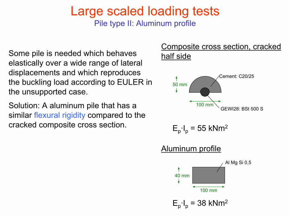
Large scaled loading testsPile type II: Aluminum profile
Some pile is needed which behaves elastically over a wide range of lateral displacements and which reproduces the buckling load according to EULER in the unsupported case.
Solution: A aluminum pile that has a similar flexural rigidity compared to the cracked composite cross section.
50 mm
Cement: C20/25
GEWI28: BSt 500 S100 mm
Composite cross section, cracked half side
Ep·Ip = 55 kNm2
Aluminum profile
40 mm
Al Mg Si 0,5
100 mm
Ep·Ip = 38 kNm2

Large scaled loading testsTest results obtained by loading of an unsupported alu-pile
0
20
40
60
80
100
120
140
160
180
200
0 600 1200
time [s]
axia
l pile
forc
e N
[kN
]
0
20
40
60
80
100
late
ral d
ispl
acem
ent i
n th
e m
iddl
e of
the
pile
w [m
m]
Ultimate bearing capacity of the unsupported composite-piles:
Nk = 55, 22 und 19 kN
Nk = 22 kN
Alupile:always

Introduction of a simple design methodDerivation
z
LHwLHwp(z)
P
zp
w0,M
N
N
wN,M
MM
T = P
T = 0
⋅
π⋅= z
Lsinw)z(w
HwM,00
Assumption of sinus shaped bending curves
⋅
π⋅= z
Lsinw)z(w
HwM,NN
Assumption of a sinus shaped deformation due to imperfection
This yields to a sinus shaped form of the load per unit length due to the lateral soil support
⋅
π⋅= z
Lsinp)z(p
HwM

Is the decisive buckling load Nki the ultimate axial load Nu of the micropile?
The pile‘s material may yield before the buckling load is reached. In this case the pile‘s material strength governs the ultimate load.
−⋅=
α
plpl N
N1MM
−⋅
⋅⋅π
⋅=
α
plpp2
2Hwpl
pl,M NN1
IELM
w
Introduction of a simple design method
lateral deformation wN,M
axia
l pile
forc
e N
A
B
D
C
wM,pl case 1wM,pl case 2
case 1
case 2