Embed Size (px)
Citation preview
Reflections on 25 years of LWR fuel modelingReflections on 25 years of LWR fuel modeling,challenges and contemporary issues
A Presentation To The
Nuclear Science and Technology Interaction Program (NSTIP) Oak Ridge National LaboratoryOak Ridge National Laboratory
Dion Sunderland
ANATECH Corp.
ANATECHLinking Theory and Practice
Nuclear Science and Technology Interaction Program (NSTIP), ORNL, July 8, 2011 - 1 -
LWR Fuel Modeling & Simulation
• Background
• Fuel Modeling & Simulation
Ch ll• Challenges– Fuel-Cladding Gap (Relocation)– PCI– Fission Gas Release
• Contemporary Issues
• Conclusions
ANATECHLinking Theory and Practice
Nuclear Science and Technology Interaction Program (NSTIP), ORNL, July 8, 2011 - 2 -
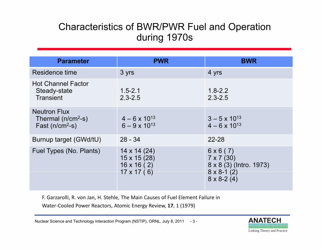
Characteristics of BWR/PWR Fuel and Operation during 1970s
Parameter PWR BWR
Residence time 3 yrs 4 yrs
Hot Channel FactorSteady-stateTransient
1.5-2.12.3-2.5
1.8-2.22.3-2.5
Neutron FluxThermal (n/cm2-s)Fast (n/cm2-s)
4 – 6 x 10¹³
6 – 9 x 10¹³ 3 – 5 x 10¹³
4 – 6 x 10¹³
Burnup target (GWd/tU) 28 - 34 22-28Burnup target (GWd/tU) 28 34 22 28
Fuel Types (No. Plants) 14 x 14 (24)15 x 15 (28)16 x 16 ( 2)17 x 17 ( 6)
6 x 6 ( 7)7 x 7 (30)8 x 8 (3) (Intro. 1973)8 x 8 1 (2)17 x 17 ( 6) 8 x 8-1 (2)8 x 8-2 (4)
F. Garzarolli, R. von Jan, H. Stehle, The Main Causes of Fuel Element Failure in
ANATECHLinking Theory and Practice
Nuclear Science and Technology Interaction Program (NSTIP), ORNL, July 8, 2011 - 3 -
Water‐Cooled Power Reactors, Atomic Energy Review, 17, 1 (1979)
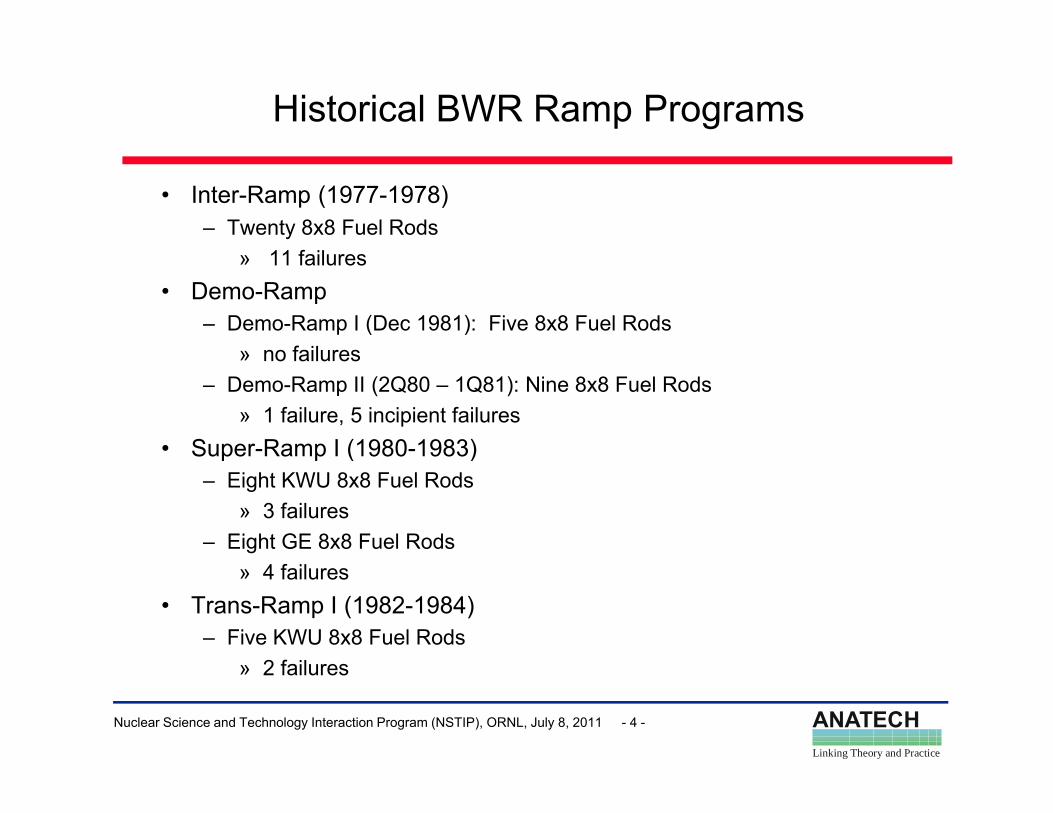
Historical BWR Ramp Programs
• Inter-Ramp (1977-1978)– Twenty 8x8 Fuel Rods
11 f il» 11 failures• Demo-Ramp
– Demo-Ramp I (Dec 1981): Five 8x8 Fuel Rods» no failures» no failures
– Demo-Ramp II (2Q80 – 1Q81): Nine 8x8 Fuel Rods» 1 failure, 5 incipient failures
• Super-Ramp I (1980-1983)p p ( )– Eight KWU 8x8 Fuel Rods
» 3 failures– Eight GE 8x8 Fuel Rods
» 4 failures• Trans-Ramp I (1982-1984)
– Five KWU 8x8 Fuel Rods2 f il
ANATECHLinking Theory and Practice
Nuclear Science and Technology Interaction Program (NSTIP), ORNL, July 8, 2011 - 4 -
» 2 failures
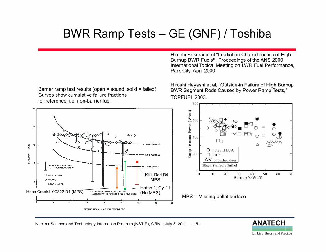
BWR Ramp Tests – GE (GNF) / ToshibaHiroshi Sakurai et al “Irradiation Characteristics of High Burnup BWR Fuels”, Proceedings of the ANS 2000 International Topical Meeting on LWR Fuel Performance, Park City, April 2000.
Barrier ramp test results (open = sound, solid = failed)Curves show cumulative failure fractionsfor reference, i.e. non-barrier fuel
Hiroshi Hayashi et al, “Outside-in Failure of High Burnup BWR Segment Rods Caused by Power Ramp Tests,”TOPFUEL 2003.
KKL R d B4KKL Rod B4
Hope Creek LYC822 D1 (MPS)MPS = Missing pellet surface
Hatch 1, Cy 21 (No MPS)
MPS
ANATECHLinking Theory and Practice
Nuclear Science and Technology Interaction Program (NSTIP), ORNL, July 8, 2011 - 5 -
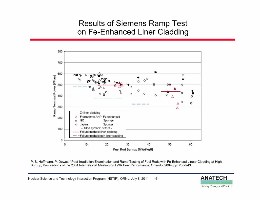
Results of Siemens Ramp Test on Fe-Enhanced Liner Cladding
P. B. Hoffmann, P. Dewes, “Post-Irradiation Examination and Ramp Testing of Fuel Rods with Fe-Enhanced Linear Cladding at High
ANATECHLinking Theory and Practice
Nuclear Science and Technology Interaction Program (NSTIP), ORNL, July 8, 2011 - 6 -
Burnup, Proceedings of the 2004 International Meeting on LWR Fuel Performance, Orlando, 2004, pp. 238-243.
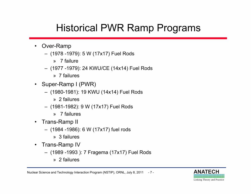
Historical PWR Ramp Programs• Over-Ramp
– (1978 -1979): 5 W (17x17) Fuel Rods» 7 failure» 7 failure
– (1977 -1979): 24 KWU/CE (14x14) Fuel Rods » 7 failures
• Super-Ramp I (PWR)Super-Ramp I (PWR)– (1980-1981): 19 KWU (14x14) Fuel Rods
» 2 failures– (1981-1982): 9 W (17x17) Fuel Rods( ) ( )
» 7 failures• Trans-Ramp II
– (1984 -1986): 6 W (17x17) fuel rods» 3 failures
• Trans-Ramp IV– (1989 -1993 ): 7 Fragema (17x17) Fuel Rods
2 f il
ANATECHLinking Theory and Practice
Nuclear Science and Technology Interaction Program (NSTIP), ORNL, July 8, 2011 - 7 -
» 2 failures
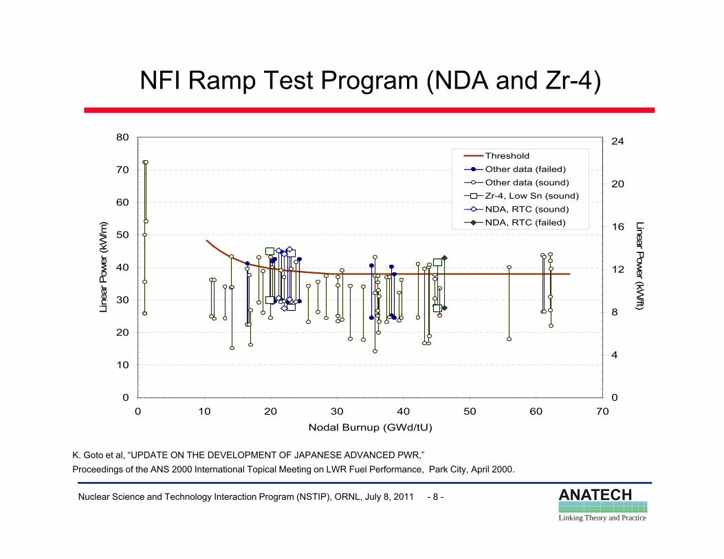
NFI Ramp Test Program (NDA and Zr-4)
70
80 24ThresholdOther data (failed)
50
60
kW/m
) 16
20
Linea
Other data (sound)Zr-4, Low Sn (sound)NDA, RTC (sound)NDA, RTC (failed)
30
40
Line
ar P
ower
(kW
8
12
ar Pow
er (kW/ft)
10
20
4
8
K Goto et al “UPDATE ON THE DEVELOPMENT OF JAPANESE ADVANCED PWR ”
00 10 20 30 40 50 60 70
Nodal Burnup (GWd/tU)
0
ANATECHLinking Theory and Practice
Nuclear Science and Technology Interaction Program (NSTIP), ORNL, July 8, 2011 - 8 -
K. Goto et al, UPDATE ON THE DEVELOPMENT OF JAPANESE ADVANCED PWR, Proceedings of the ANS 2000 International Topical Meeting on LWR Fuel Performance, Park City, April 2000.
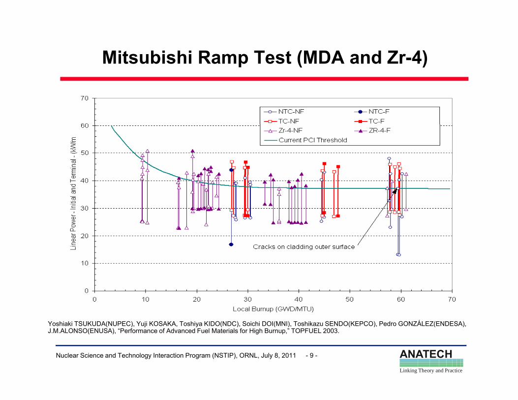
Mitsubishi Ramp Test (MDA and Zr-4)
Yoshiaki TSUKUDA(NUPEC), Yuji KOSAKA, Toshiya KIDO(NDC), Soichi DOI(MNI), Toshikazu SENDO(KEPCO), Pedro GONZÁLEZ(ENDESA),
ANATECHLinking Theory and Practice
Nuclear Science and Technology Interaction Program (NSTIP), ORNL, July 8, 2011 - 9 -
( ), j , y ( ), ( ), ( ), ( ),J.M.ALONSO(ENUSA), “Performance of Advanced Fuel Materials for High Burnup,” TOPFUEL 2003.
Evolution in Fuel Designs and Operations
• 1980s– PWR: 17x17 plants (3 loops, 157 assy; 4 loops, 193 assy) become the
standardstandard– BWR: 9x9 fuel introduced by Siemens & Exxon (ANF) and SVEA-64,
SVEA-100 designs introduced by ABB– 3 annual cycles for PWR fuel, 4 annual cycles for BWR fuel standardy , y– Consideration for higher burnup and 18-month cycles in US initiated– Annual cycle length 270-330 efpd– Discharge burnups increase to mid-40s GWd/tUsc a ge bu ups c ease to d 0s G d/tU
• 1990s– 4-5 annual cycles (Europe), shorter lifetime with recycling– 3 x 18-mo (18-mo cycle 460-510 EFPD)3 x 18 mo (18 mo cycle 460 510 EFPD)– Consideration for 24-mo cycles, moderate duty PWRs (14x14, 15x15,
16x16) and BWRs– GNF/Siemens(AREVA) introduce advanced 9x9 and start
ANATECHLinking Theory and Practice
Nuclear Science and Technology Interaction Program (NSTIP), ORNL, July 8, 2011 - 10 -
( )development of 10x10 fuel
Evolution in Fuel Designs and Operations (Cont’d)( )
• 1990s– 24-mo cycle (600-690 EFPD)
19 20 21 l h d l t PWR l t– 19-20-21 mo cycle schedule at one PWR plant– Discharge burnups increase to 50 GWd/tU– Utilities start power uprates: MUR (< 2%), Stretch (< 7%), Extended
(<20%)(<20%).
• 2000sMost 14x14 several 15x15 plants and some 16x16 plants on 24 mo– Most 14x14, several 15x15 plants, and some 16x16 plants on 24-mo cycles. Batch sizes approaching ½ core in some cases.
– Many US BWRs move to 24-month cycles– Plant uprates continuePlant uprates continue– High capacity 18-mo cycles approach 530 EFPD
ANATECHLinking Theory and Practice
Nuclear Science and Technology Interaction Program (NSTIP), ORNL, July 8, 2011 - 11 -
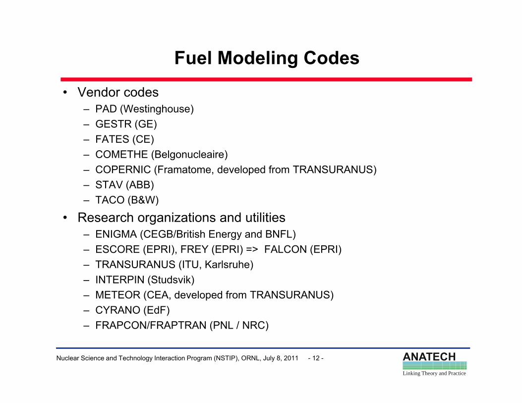
Fuel Modeling Codes
• Vendor codes– PAD (Westinghouse)– GESTR (GE)GESTR (GE)– FATES (CE)– COMETHE (Belgonucleaire)– COPERNIC (Framatome, developed from TRANSURANUS)– STAV (ABB)– TACO (B&W)
• Research organizations and utilities– ENIGMA (CEGB/British Energy and BNFL)– ESCORE (EPRI), FREY (EPRI) => FALCON (EPRI)– TRANSURANUS (ITU, Karlsruhe)
INTERPIN (Studsvik)– INTERPIN (Studsvik)– METEOR (CEA, developed from TRANSURANUS)– CYRANO (EdF)– FRAPCON/FRAPTRAN (PNL / NRC)
ANATECHLinking Theory and Practice
Nuclear Science and Technology Interaction Program (NSTIP), ORNL, July 8, 2011 - 12 -
FRAPCON/FRAPTRAN (PNL / NRC)
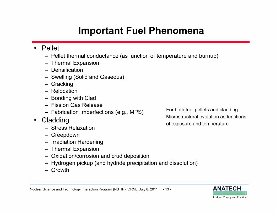
Important Fuel Phenomena• Pellet
– Pellet thermal conductance (as function of temperature and burnup)– Thermal Expansion– Densification– Swelling (Solid and Gaseous)– Cracking– Relocation– Bonding with Clad– Fission Gas Release– Fabrication Imperfections (e.g., MPS)
• CladdingFor both fuel pellets and cladding:Microstructural evolution as functions • Cladding
– Stress Relaxation – Creepdown– Irradiation Hardening
Th l E i
of exposure and temperature
– Thermal Expansion– Oxidation/corrosion and crud deposition– Hydrogen pickup (and hydride precipitation and dissolution)– Growth
ANATECHLinking Theory and Practice
Nuclear Science and Technology Interaction Program (NSTIP), ORNL, July 8, 2011 - 13 -
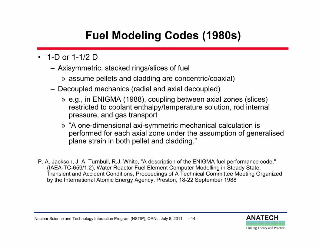
Fuel Modeling Codes (1980s)
• 1-D or 1-1/2 D– Axisymmetric, stacked rings/slices of fuel
ll t d l ddi t i / i l)» assume pellets and cladding are concentric/coaxial)– Decoupled mechanics (radial and axial decoupled)
» e.g., in ENIGMA (1988), coupling between axial zones (slices) restricted to coolant enthalpy/temperature solution rod internalrestricted to coolant enthalpy/temperature solution, rod internal pressure, and gas transport
» “A one-dimensional axi-symmetric mechanical calculation is performed for each axial zone under the assumption of generalised
l t i i b th ll t d l ddi ”plane strain in both pellet and cladding.”
P. A. Jackson, J. A. Turnbull, R.J. White, "A description of the ENIGMA fuel performance code," (IAEA-TC-659/1.2), Water Reactor Fuel Element Computer Modelling in Steady State, ( C 659/ ), a e eac o ue e e Co pu e ode g S eady S a e,Transient and Accident Conditions, Proceedings of A Technical Committee Meeting Organized by the International Atomic Energy Agency, Preston, 18-22 September 1988
ANATECHLinking Theory and Practice
Nuclear Science and Technology Interaction Program (NSTIP), ORNL, July 8, 2011 - 14 -
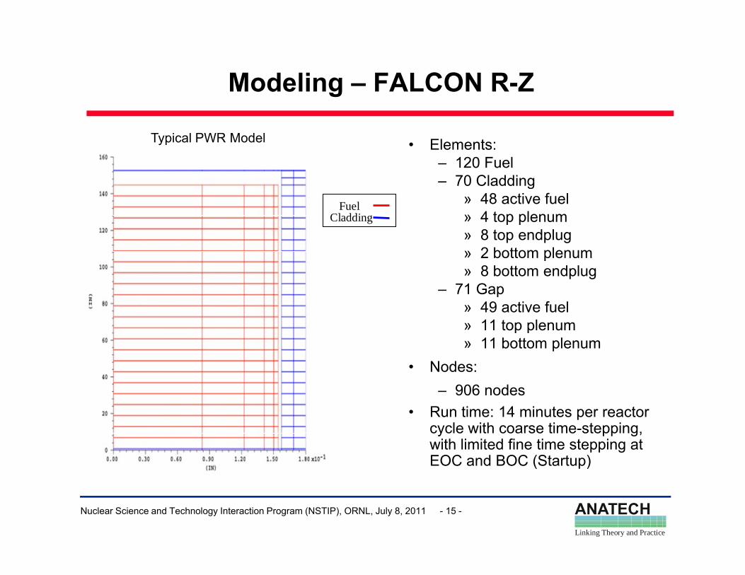
Modeling – FALCON R-Z
• Elements:– 120 Fuel
70 Cladding
Typical PWR Model
– 70 Cladding» 48 active fuel» 4 top plenum» 8 top endplug» 2 bottom plenum
Fuel
Cladding
» 2 bottom plenum» 8 bottom endplug
– 71 Gap» 49 active fuel» 11 top plenum» 11 top plenum» 11 bottom plenum
• Nodes: – 906 nodes
• Run time: 14 minutes per reactor cycle with coarse time-stepping, with limited fine time stepping at EOC and BOC (Startup)
ANATECHLinking Theory and Practice
Nuclear Science and Technology Interaction Program (NSTIP), ORNL, July 8, 2011 - 15 -
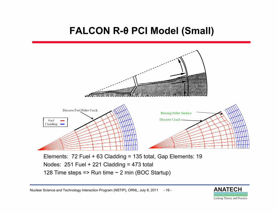
FALCON R-θ PCI Model (Small)
Missing Pellet SurfaceMissing Pellet Surface
Discrete CrackDiscrete Crack
Elements: 72 Fuel + 63 Cladding = 135 total, Gap Elements: 19Nodes: 251 Fuel + 221 Cladding = 473 total128 Time steps => Run time ~ 2 min (BOC Startup)
ANATECHLinking Theory and Practice
Nuclear Science and Technology Interaction Program (NSTIP), ORNL, July 8, 2011 - 16 -
p ( p)
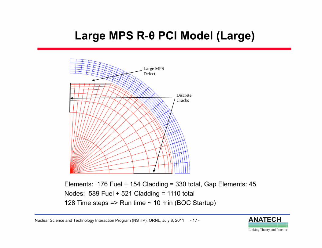
Large MPS R-θ PCI Model (Large)
Large MPS Defect
Discrete Cracks
Elements: 176 Fuel + 154 Cladding = 330 total, Gap Elements: 45Nodes: 589 Fuel + 521 Cladding = 1110 total128 Time steps => Run time ~ 10 min (BOC Startup)
ANATECHLinking Theory and Practice
Nuclear Science and Technology Interaction Program (NSTIP), ORNL, July 8, 2011 - 17 -
128 Time steps => Run time ~ 10 min (BOC Startup)
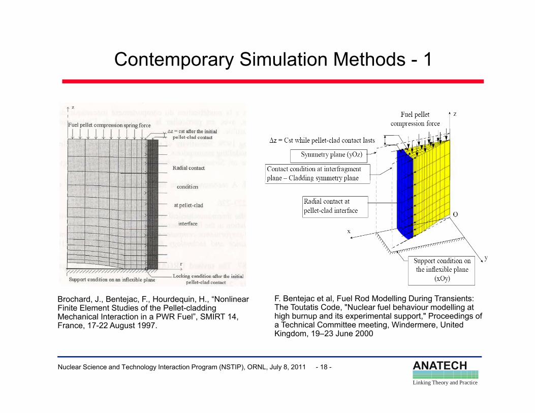
Contemporary Simulation Methods - 1
Brochard, J., Bentejac, F., Hourdequin, H., “Nonlinear Finite Element Studies of the Pellet-cladding Mechanical Interaction in a PWR Fuel”, SMIRT 14, France, 17-22 August 1997.
F. Bentejac et al, Fuel Rod Modelling During Transients: The Toutatis Code, "Nuclear fuel behaviour modelling at high burnup and its experimental support," Proceedings of a Technical Committee meeting, Windermere, United Kingdom, 19–23 June 2000
ANATECHLinking Theory and Practice
Nuclear Science and Technology Interaction Program (NSTIP), ORNL, July 8, 2011 - 18 -
g ,
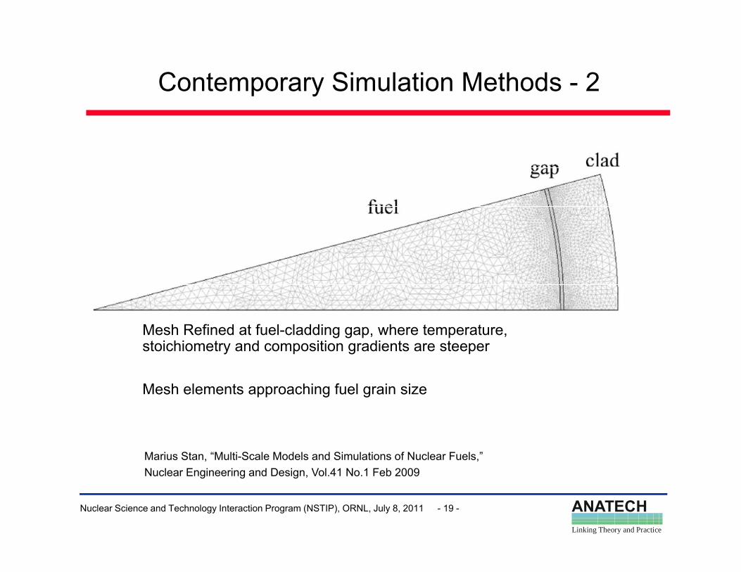
Contemporary Simulation Methods - 2
Mesh Refined at fuel-cladding gap, where temperature, stoichiometry and composition gradients are steeper
Mesh elements approaching fuel grain sizees e e e s app oac g ue g a s e
Marius Stan, “Multi-Scale Models and Simulations of Nuclear Fuels,”
ANATECHLinking Theory and Practice
Nuclear Science and Technology Interaction Program (NSTIP), ORNL, July 8, 2011 - 19 -
Nuclear Engineering and Design, Vol.41 No.1 Feb 2009
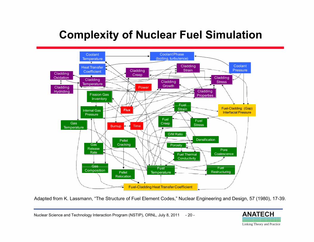
Complexity of Nuclear Fuel Simulation
Cladding
Coolant Temperature
Coolant PressureCladding
Creep
CladdingStrain
Coolant Phase(boiling, turbulence)
Heat Transfer Coefficientg
Oxidation
Power
CladdingTemperature
Creep
CladdingGrowth
CladdingProperties
CladdingStress
Fission GasInventory
Fuel
CladdingHydriding
Flux
Burnup Time
Internal Gas Pressure
GasTemperature
Fuel Creep
Fuel Strain
Fuel Stress
Fuel-Cladding (Gap) Interfacial Pressure
O/M Ratio
GasRelease
Rate
Gas
Pellet Cracking
F l
Fuel Thermal Conductivity
F l
Pore Coalescence
DensificationPorosity
GasComposition Fuel
Temperature
Fuel-Cladding Heat Transfer Coefficient
FuelRestructuringPellet
Relocation
Ad t d f K L “Th St t f F l El t C d ” N l E i i d D i 57 (1980) 17 39
ANATECHLinking Theory and Practice
Nuclear Science and Technology Interaction Program (NSTIP), ORNL, July 8, 2011 - 20 -
Adapted from K. Lassmann, “The Structure of Fuel Element Codes,” Nuclear Engineering and Design, 57 (1980), 17-39.
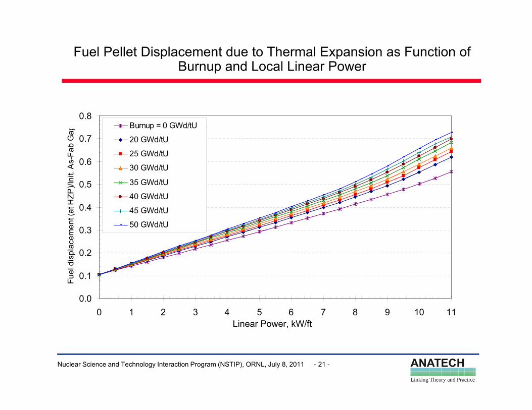
Fuel Pellet Displacement due to Thermal Expansion as Function of Burnup and Local Linear Power
0.8Burnup = 0 GWd/tU
0.6
0.7
nit.
As-
Fab
Gap
Burnup 0 GWd/tU
20 GWd/tU
25 GWd/tU
30 GWd/tU
3 GWd/ U
0 3
0.4
0.5
men
t (at
HZP
)/In 35 GWd/tU
40 GWd/tU
45 GWd/tU
50 GWd/tU
0.1
0.2
0.3
Fuel
dis
plac
em
0.00 1 2 3 4 5 6 7 8 9 10 11
Linear Power, kW/ft
F
ANATECHLinking Theory and Practice
Nuclear Science and Technology Interaction Program (NSTIP), ORNL, July 8, 2011 - 21 -
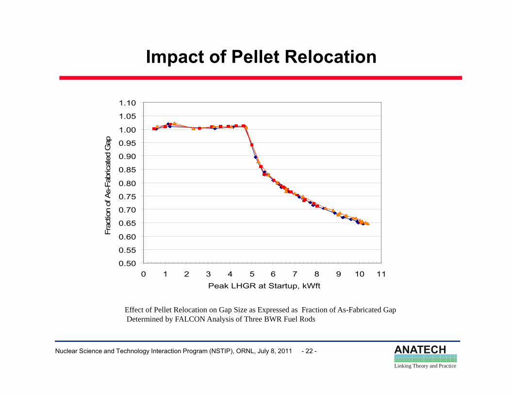
Impact of Pellet Relocation
1.05
1.10
1.05
1.10
0.85
0.90
0.95
1.00
ricat
ed G
ap
0.85
0.90
0.95
1.00
ricat
ed G
ap
0 65
0.70
0.75
0.80
ctio
n of
As-
Fabr
0 65
0.70
0.75
0.80
ctio
n of
As-
Fabr
0.50
0.55
0.60
0.65
0 1 2 3 4 5 6 7 8 9 10 11
Frac
0.50
0.55
0.60
0.65
0 1 2 3 4 5 6 7 8 9 10 11
Frac
0 1 2 3 4 5 6 7 8 9 10 11Peak LHGR at Startup, kWft
0 1 2 3 4 5 6 7 8 9 10 11Peak LHGR at Startup, kWft
Effect of Pellet Relocation on Gap Size as Expressed as Fraction of As-Fabricated GapDetermined by FALCON Analysis of Three BWR Fuel Rods
ANATECHLinking Theory and Practice
Nuclear Science and Technology Interaction Program (NSTIP), ORNL, July 8, 2011 - 22 -
y y
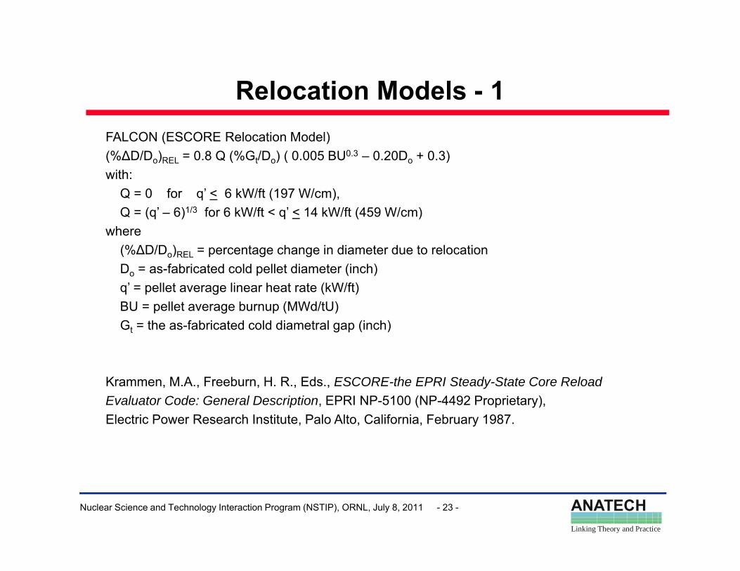
Relocation Models - 1FALCON (ESCORE Relocation Model)(%∆D/Do)REL = 0.8 Q (%Gt/Do) ( 0.005 BU0.3 – 0.20Do + 0.3)with:with:
Q = 0 for q’ < 6 kW/ft (197 W/cm),Q = (q’ – 6)1/3 for 6 kW/ft < q’ < 14 kW/ft (459 W/cm)
where (%∆D/D ) = percentage change in diameter due to relocation(%∆D/Do)REL = percentage change in diameter due to relocationDo = as-fabricated cold pellet diameter (inch)q’ = pellet average linear heat rate (kW/ft)BU = pellet average burnup (MWd/tU)G th f b i t d ld di t l (i h)Gt = the as-fabricated cold diametral gap (inch)
Krammen, M.A., Freeburn, H. R., Eds., ESCORE-the EPRI Steady-State Core ReloadEvaluator Code: General Description, EPRI NP-5100 (NP-4492 Proprietary), Electric Power Research Institute, Palo Alto, California, February 1987.
ANATECHLinking Theory and Practice
Nuclear Science and Technology Interaction Program (NSTIP), ORNL, July 8, 2011 - 23 -
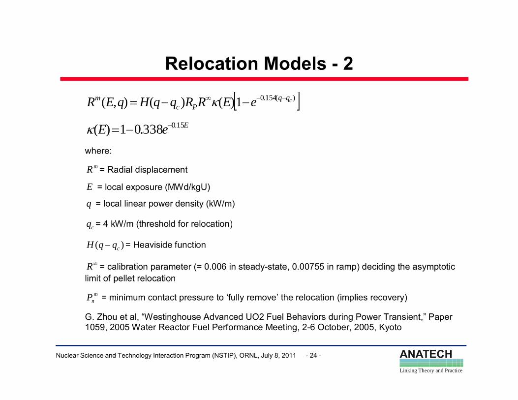
Relocation Models - 2
[ ])(154.01)()(),( cqqPc
m eERRqqHqER −−∞ −−= κ
E150)( EeE 15.0338.01)( −−=κ
where: mR = Radial displacement
E = local exposure (MWd/kgU)
q = local linear power density (kW/m)
q = 4 kW/m (threshold for relocation)cq 4 kW/m (threshold for relocation)
)( cqqH − = Heaviside function
∞R = calibration parameter (= 0.006 in steady-state, 0.00755 in ramp) deciding the asymptotic li it f ll t l tilimit of pellet relocation
mnP = minimum contact pressure to ‘fully remove’ the relocation (implies recovery)
G. Zhou et al, “Westinghouse Advanced UO2 Fuel Behaviors during Power Transient,” Paper 1059 2005 Water Reactor Fuel Performance Meeting 2 6 October 2005 Kyoto
ANATECHLinking Theory and Practice
Nuclear Science and Technology Interaction Program (NSTIP), ORNL, July 8, 2011 - 24 -
1059, 2005 Water Reactor Fuel Performance Meeting, 2-6 October, 2005, Kyoto
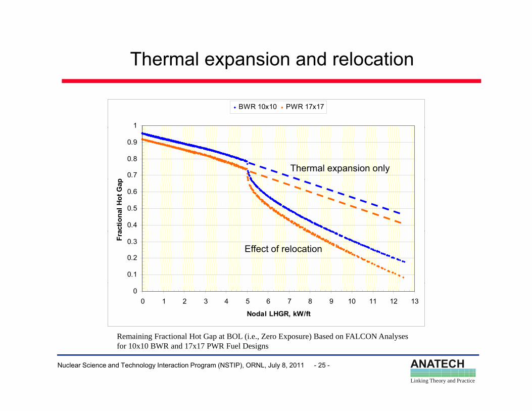
Thermal expansion and relocation
1
BWR 10x10 PWR 17x17
0.7
0.8
0.9
p
Thermal expansion only
0.4
0.5
0.6
actio
nal H
ot G
ap
0.1
0.2
0.3Fra
Effect of relocation
00 1 2 3 4 5 6 7 8 9 10 11 12 13
Nodal LHGR, kW/ft
Remaining Fractional Hot Gap at BOL (i e Zero E pos re) Based on FALCON Anal ses
ANATECHLinking Theory and Practice
Nuclear Science and Technology Interaction Program (NSTIP), ORNL, July 8, 2011 - 25 -
Remaining Fractional Hot Gap at BOL (i.e., Zero Exposure) Based on FALCON Analyses for 10x10 BWR and 17x17 PWR Fuel Designs
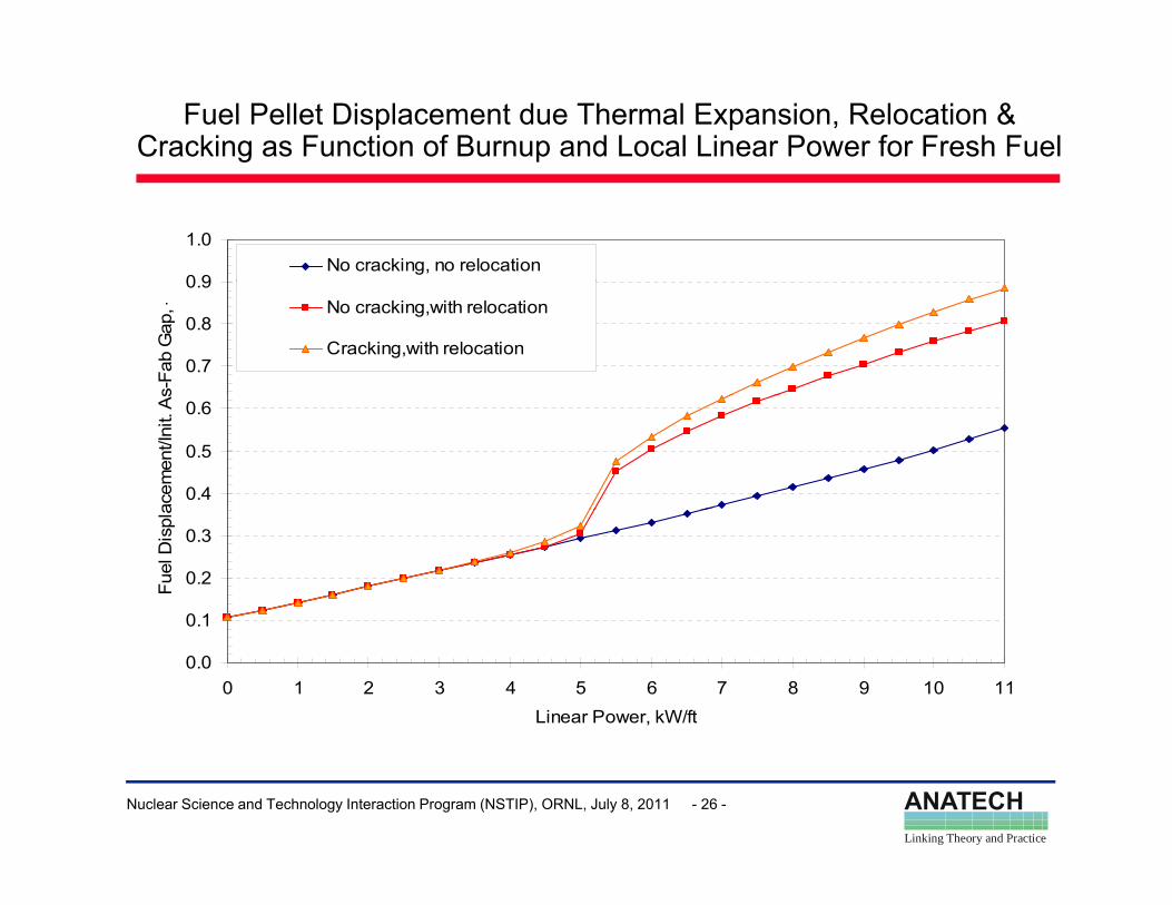
Fuel Pellet Displacement due Thermal Expansion, Relocation & Cracking as Function of Burnup and Local Linear Power for Fresh Fuel
0 9
1.0No cracking, no relocation
0.7
0.8
0.9
s-Fa
b G
ap, - No cracking,with relocation
Cracking,with relocation
0.4
0.5
0.6
acem
ent/I
nit.
As
0 1
0.2
0.3
Fuel
Dis
pla
0.0
0.1
0 1 2 3 4 5 6 7 8 9 10 11Linear Power, kW/ft
ANATECHLinking Theory and Practice
Nuclear Science and Technology Interaction Program (NSTIP), ORNL, July 8, 2011 - 26 -
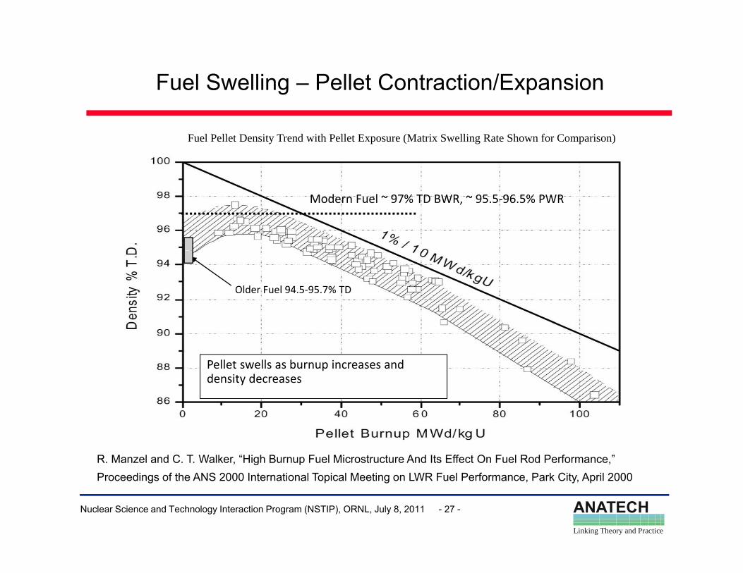
Fuel Swelling – Pellet Contraction/Expansion
Fuel Pellet Density Trend with Pellet Exposure (Matrix Swelling Rate Shown for Comparison)
Modern Fuel ~ 97% TD BWR, ~ 95.5‐96.5% PWR
Older Fuel 94.5‐95.7% TD
Pellet swells as burnup increases and density decreases
R. Manzel and C. T. Walker, “High Burnup Fuel Microstructure And Its Effect On Fuel Rod Performance,”
ANATECHLinking Theory and Practice
Nuclear Science and Technology Interaction Program (NSTIP), ORNL, July 8, 2011 - 27 -
Proceedings of the ANS 2000 International Topical Meeting on LWR Fuel Performance, Park City, April 2000
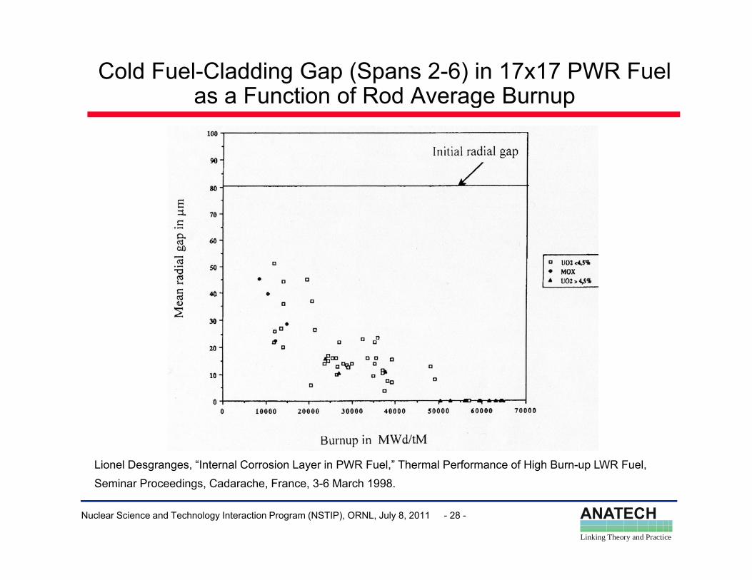
Cold Fuel-Cladding Gap (Spans 2-6) in 17x17 PWR Fuel as a Function of Rod Average Burnupg p
Lionel Desgranges, “Internal Corrosion Layer in PWR Fuel,” Thermal Performance of High Burn-up LWR Fuel,
ANATECHLinking Theory and Practice
Nuclear Science and Technology Interaction Program (NSTIP), ORNL, July 8, 2011 - 28 -
Seminar Proceedings, Cadarache, France, 3-6 March 1998.
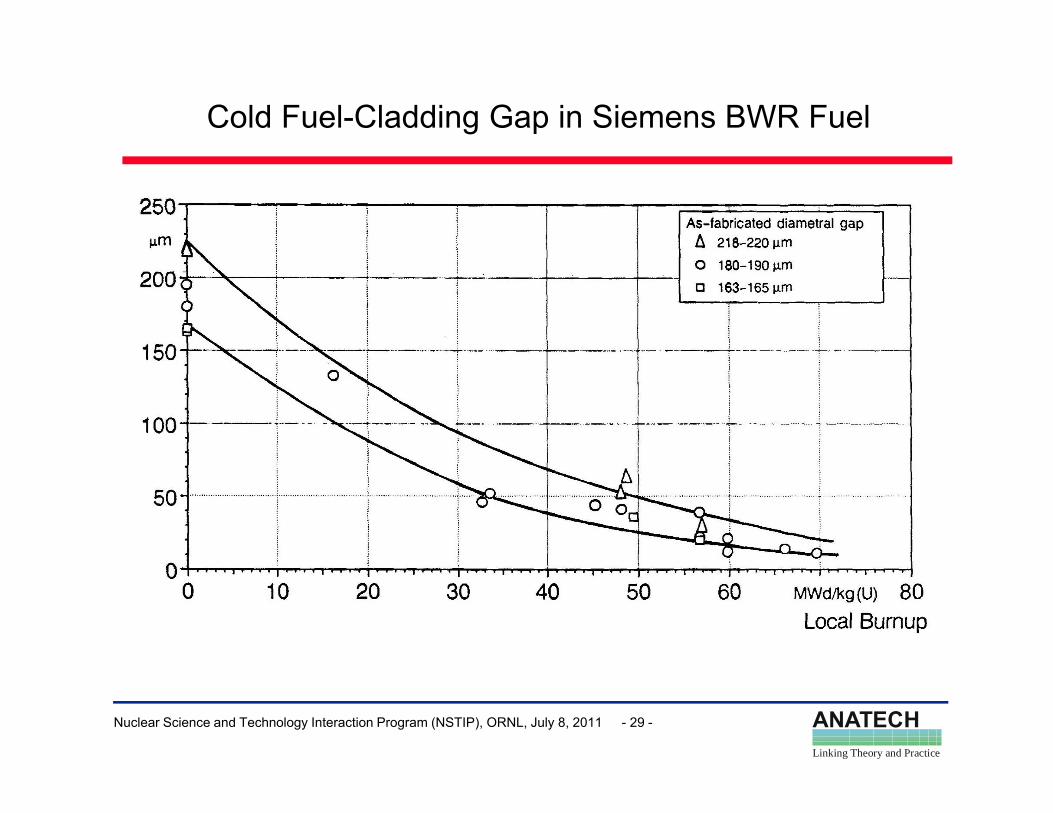
Cold Fuel-Cladding Gap in Siemens BWR Fuel
ANATECHLinking Theory and Practice
Nuclear Science and Technology Interaction Program (NSTIP), ORNL, July 8, 2011 - 29 -
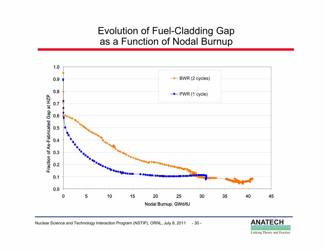
Evolution of Fuel-Cladding Gap as a Function of Nodal Burnupp
0 9
1.0
BWR (2 cycles)0 9
1.0
BWR (2 cycles)
0.7
0.8
0.9
at H
ZP
BWR (2 cycles)
PWR (1 cycle)
0.7
0.8
0.9
at H
ZP
BWR (2 cycles)
PWR (1 cycle)
0 4
0.5
0.6
Fabr
icat
ed G
ap
0 4
0.5
0.6
Fabr
icat
ed G
ap
0.2
0.3
0.4
Frac
tion
of A
s-F
0.2
0.3
0.4
Frac
tion
of A
s-F
0.0
0.1
0 5 10 15 20 25 30 35 40 45
Nodal Burnup GWd/tU
0.0
0.1
0 5 10 15 20 25 30 35 40 45
Nodal Burnup GWd/tU
ANATECHLinking Theory and Practice
Nuclear Science and Technology Interaction Program (NSTIP), ORNL, July 8, 2011 - 30 -
Nodal Burnup, GWd/tUNodal Burnup, GWd/tU
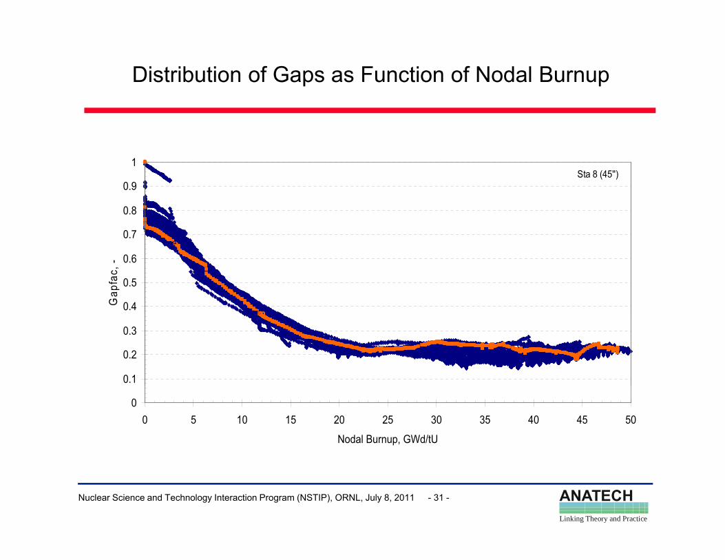
Distribution of Gaps as Function of Nodal Burnup
1Sta 8 (45'')
0.7
0.8
0.9Sta 8 (45 )
0.4
0.5
0.6
Gap
fac,
-
0.1
0.2
0.3
00 5 10 15 20 25 30 35 40 45 50
Nodal Burnup, GWd/tU
ANATECHLinking Theory and Practice
Nuclear Science and Technology Interaction Program (NSTIP), ORNL, July 8, 2011 - 31 -
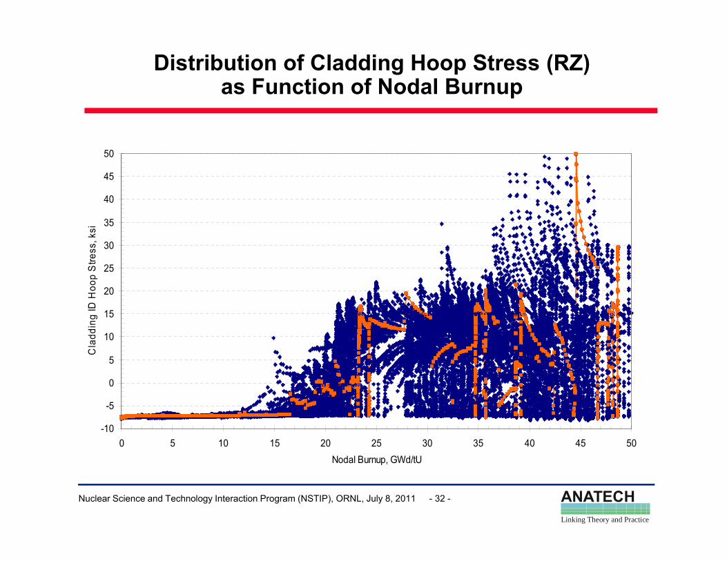
Distribution of Cladding Hoop Stress (RZ) as Function of Nodal Burnup
45
50
30
35
40
45
s, k
si
15
20
25
30
g ID
Hoo
p S
tress
0
5
10
15
Cla
ddin
g
-10
-5
0 5 10 15 20 25 30 35 40 45 50N d l B GWd/tU
ANATECHLinking Theory and Practice
Nuclear Science and Technology Interaction Program (NSTIP), ORNL, July 8, 2011 - 32 -
Nodal Burnup, GWd/tU
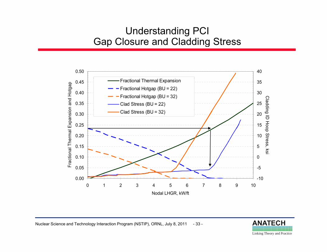
Understanding PCIGap Closure and Cladding Stressp g
0.50 400.50 40
0.35
0.40
0.45
on a
nd H
otga
p
25
30
35
Claddin
Fractional Thermal ExpansionFractional Hotgap (BU = 22)Fractional Hotgap (BU = 32)Clad Stress (BU = 22)Cl d S (BU 32)
0.35
0.40
0.45
on a
nd H
otga
p
25
30
35
Claddin
Fractional Thermal ExpansionFractional Hotgap (BU = 22)Fractional Hotgap (BU = 32)Clad Stress (BU = 22)Cl d S (BU 32)
0.20
0.25
0.30
herm
al E
xpan
sio
10
15
20
ng ID H
oop Stres
Clad Stress (BU = 32)
0.20
0.25
0.30
herm
al E
xpan
sio
10
15
20
ng ID H
oop Stres
Clad Stress (BU = 32)
0.05
0.10
0.15
Frac
tiona
l Th
-5
0
5
ss, ksi
0.05
0.10
0.15
Frac
tiona
l Th
-5
0
5
ss, ksi
0.000 1 2 3 4 5 6 7 8 9 10
Nodal LHGR, kW/ft
-100.000 1 2 3 4 5 6 7 8 9 10
Nodal LHGR, kW/ft
-10
ANATECHLinking Theory and Practice
Nuclear Science and Technology Interaction Program (NSTIP), ORNL, July 8, 2011 - 33 -
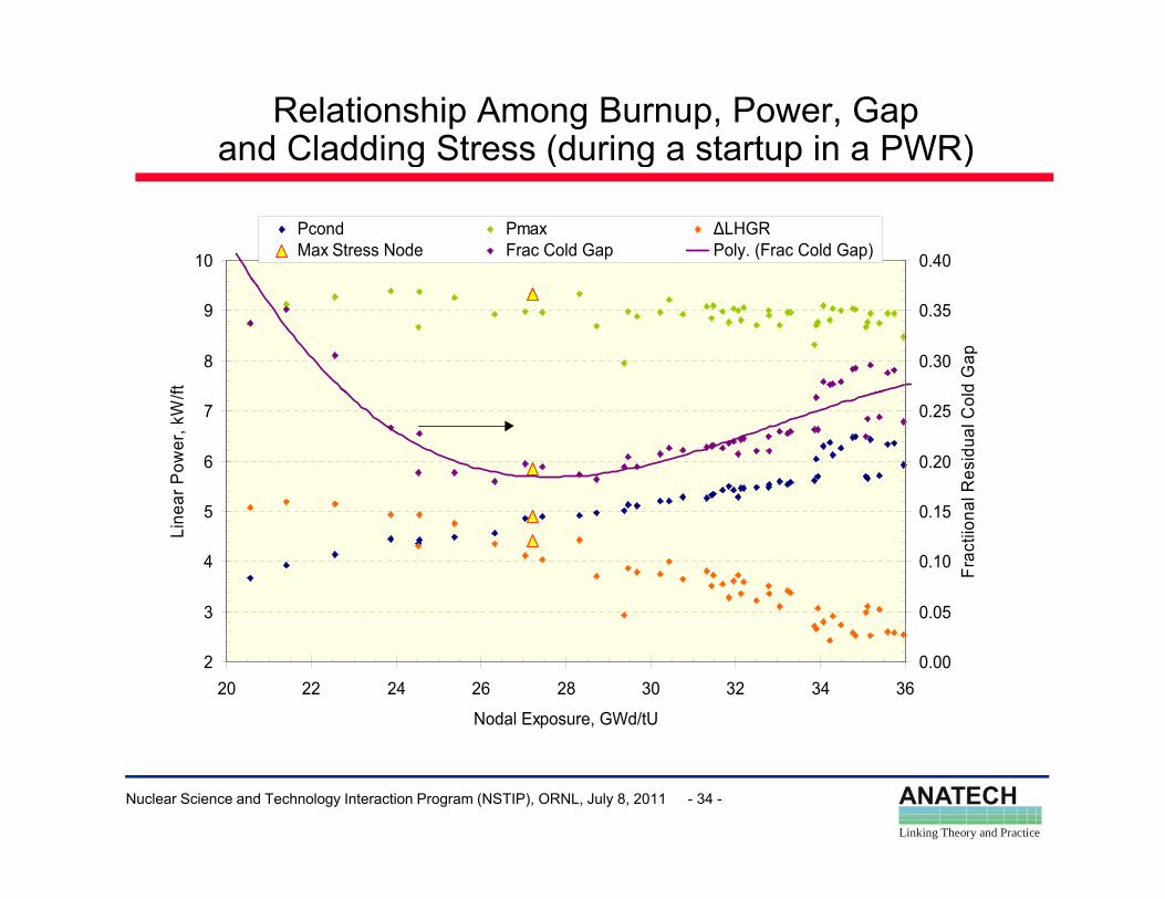
Relationship Among Burnup, Power, Gapand Cladding Stress (during a startup in a PWR)g ( g p )
10 0.40
Pcond Pmax ∆LHGRMax Stress Node Frac Cold Gap Poly. (Frac Cold Gap)
8
9
ft
0.30
0.35
d G
ap
5
6
7
ear P
ower
, kW
/f
0 15
0.20
0.25
al R
esid
ual C
ol
3
4
5
Line
0.05
0.10
0.15
Frac
tiion
a
220 22 24 26 28 30 32 34 36
Nodal Exposure, GWd/tU
0.00
ANATECHLinking Theory and Practice
Nuclear Science and Technology Interaction Program (NSTIP), ORNL, July 8, 2011 - 34 -
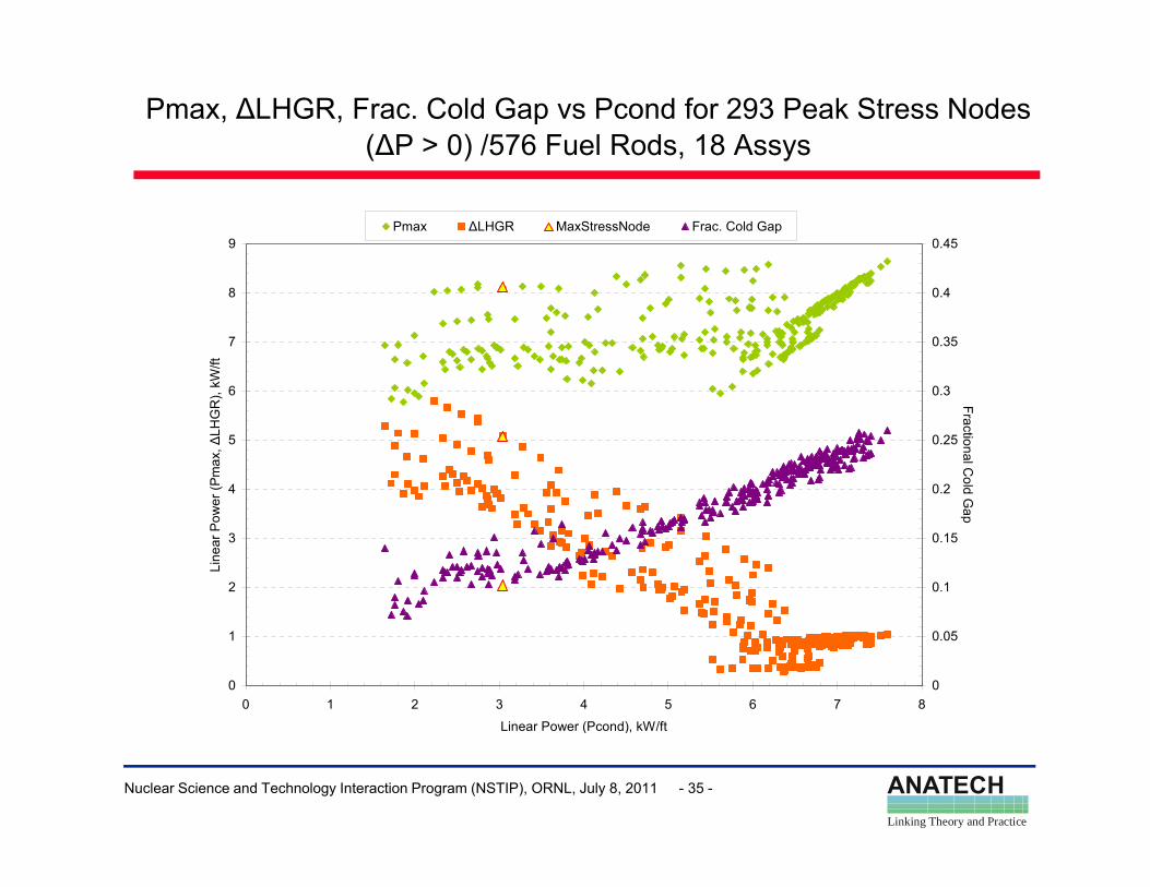
Pmax, ∆LHGR, Frac. Cold Gap vs Pcond for 293 Peak Stress Nodes (∆P > 0) /576 Fuel Rods, 18 Assys
9 0.45Pmax ∆LHGR MaxStressNode Frac. Cold Gap
6
7
8
kW/ft
0 3
0.35
0.4
4
5
6
er (P
max
, ∆LH
GR
),
0.2
0.25
0.3
Fractional Cold G
2
3
Line
ar P
owe
0.1
0.15
Gap
0
1
0 1 2 3 4 5 6 7 8
Li P (P d) kW/ft
0
0.05
ANATECHLinking Theory and Practice
Nuclear Science and Technology Interaction Program (NSTIP), ORNL, July 8, 2011 - 35 -
Linear Power (Pcond), kW/ft
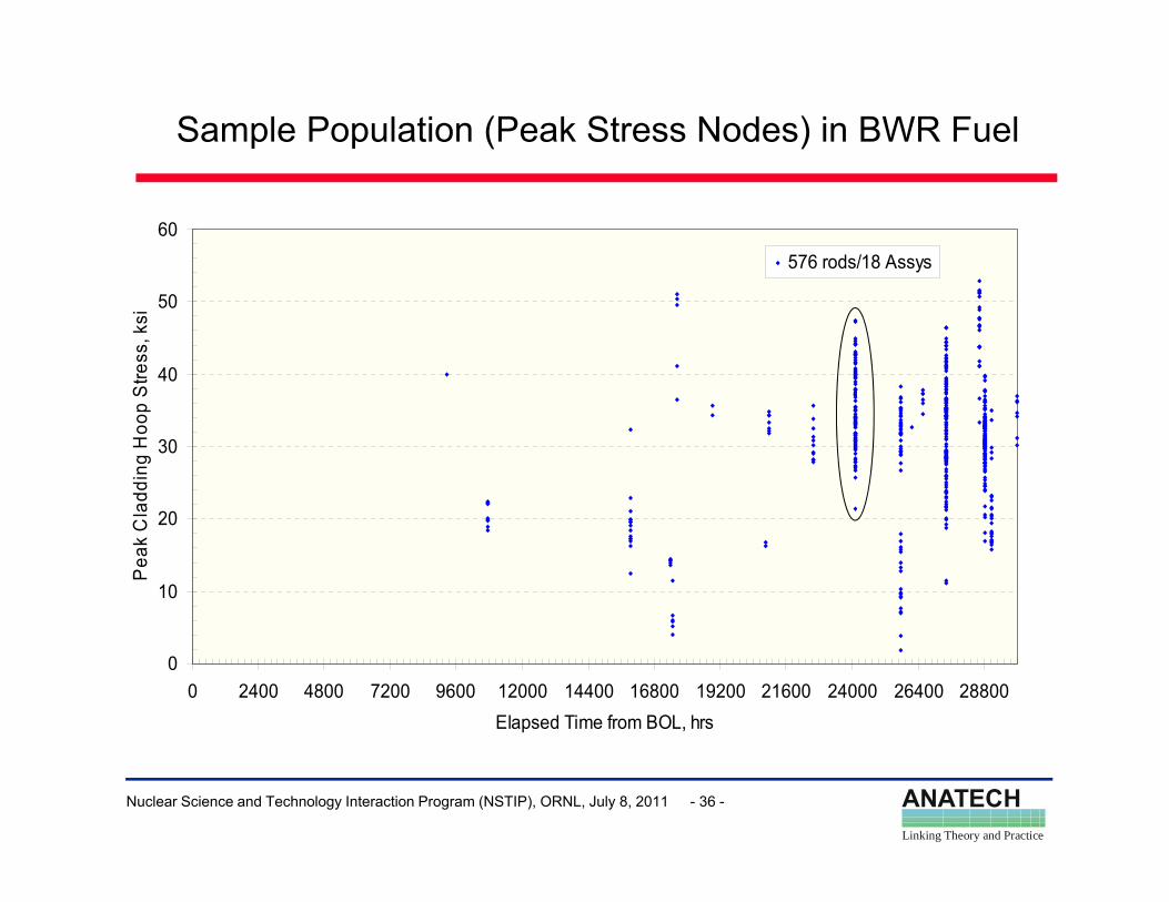
Sample Population (Peak Stress Nodes) in BWR Fuel
60
576 rods/18 Assys
40
50
Stre
ss, k
si
30
addi
ng H
oop
S
10
20
Pea
k C
la
00 2400 4800 7200 9600 12000 14400 16800 19200 21600 24000 26400 28800
Elapsed Time from BOL, hrs
ANATECHLinking Theory and Practice
Nuclear Science and Technology Interaction Program (NSTIP), ORNL, July 8, 2011 - 36 -
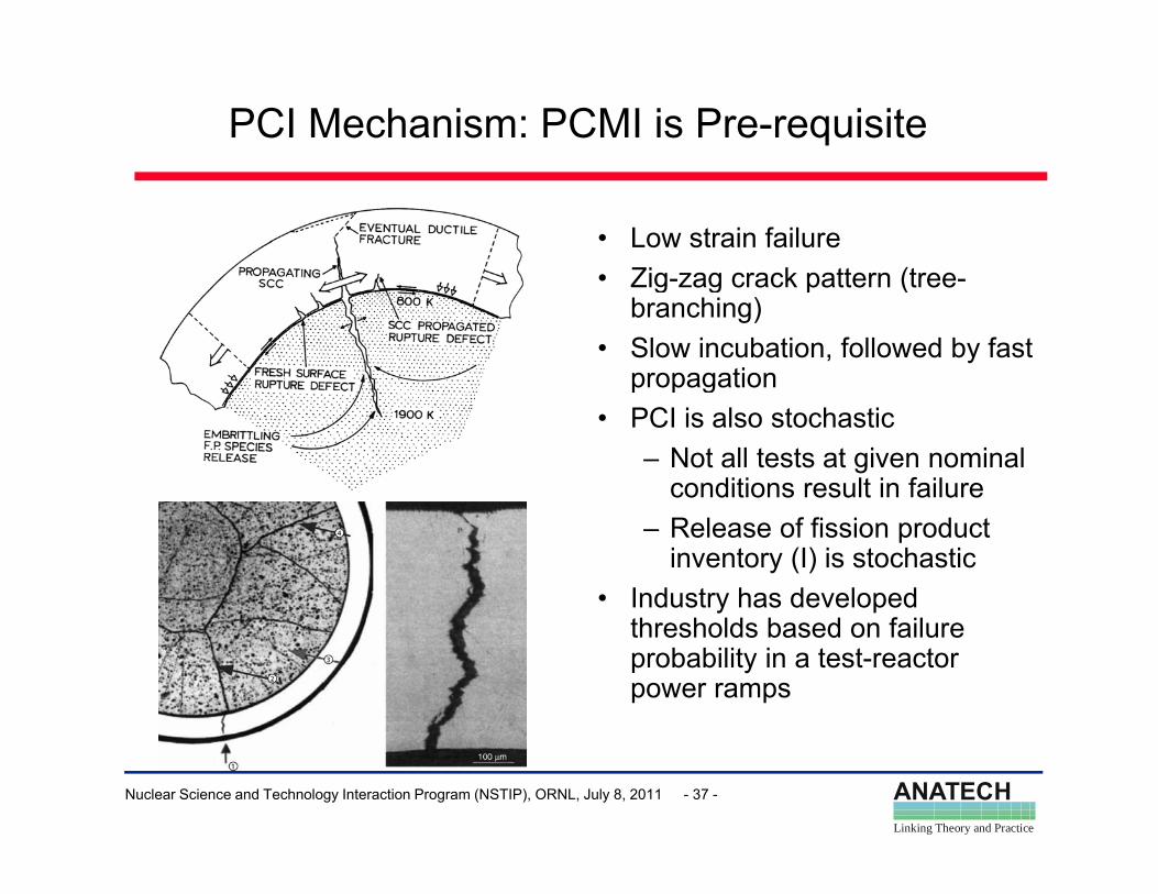
PCI Mechanism: PCMI is Pre-requisite
• Low strain failure• Zig zag crack pattern (tree• Zig-zag crack pattern (tree-
branching)• Slow incubation, followed by fast
propagationp p g• PCI is also stochastic
– Not all tests at given nominal conditions result in failure
– Release of fission product inventory (I) is stochastic
• Industry has developed thresholds based on failure probability in a test-reactor power ramps
ANATECHLinking Theory and Practice
Nuclear Science and Technology Interaction Program (NSTIP), ORNL, July 8, 2011 - 37 -
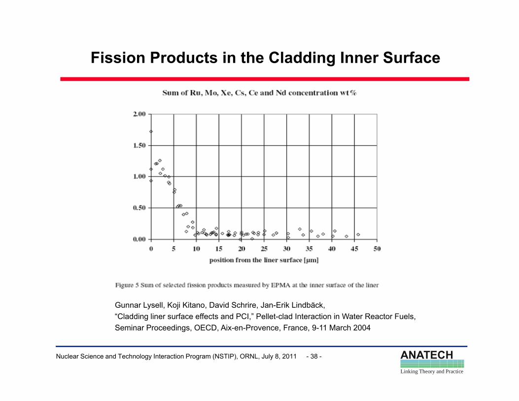
Fission Products in the Cladding Inner Surface
Gunnar Lysell, Koji Kitano, David Schrire, Jan-Erik Lindbäck, “Cladding liner surface effects and PCI,” Pellet-clad Interaction in Water Reactor Fuels, Seminar Proceedings OECD Aix en Provence France 9 11 March 2004
ANATECHLinking Theory and Practice
Nuclear Science and Technology Interaction Program (NSTIP), ORNL, July 8, 2011 - 38 -
Seminar Proceedings, OECD, Aix-en-Provence, France, 9-11 March 2004
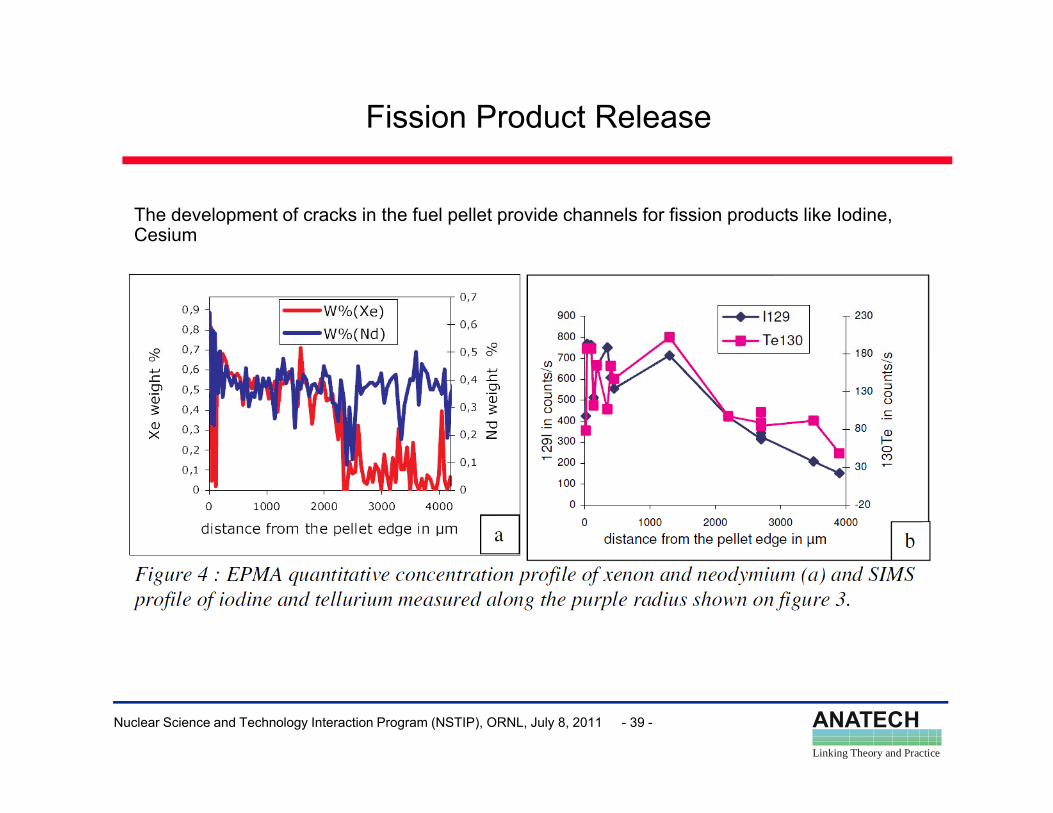
Fission Product Release
The development of cracks in the fuel pellet provide channels for fission products like Iodine, Cesium
ANATECHLinking Theory and Practice
Nuclear Science and Technology Interaction Program (NSTIP), ORNL, July 8, 2011 - 39 -
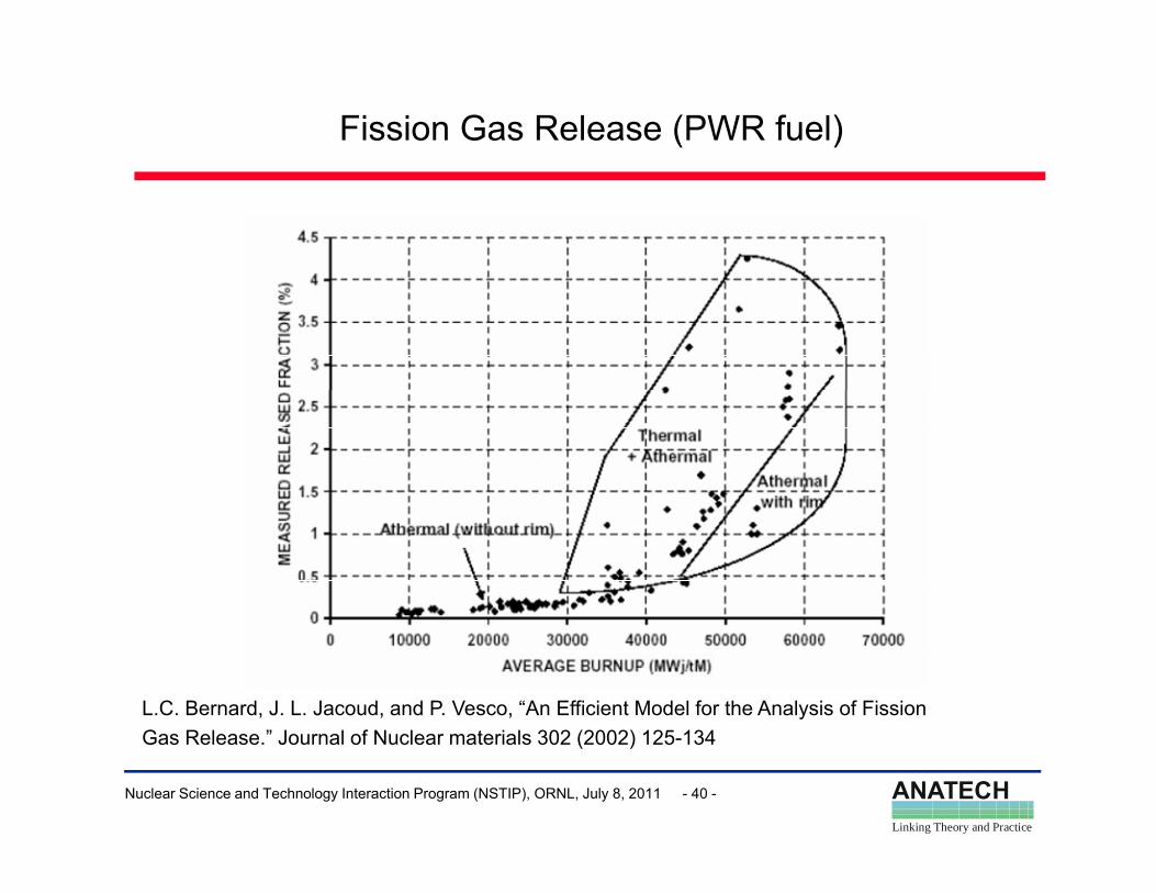
Fission Gas Release (PWR fuel)
L.C. Bernard, J. L. Jacoud, and P. Vesco, “An Efficient Model for the Analysis of Fission
ANATECHLinking Theory and Practice
Nuclear Science and Technology Interaction Program (NSTIP), ORNL, July 8, 2011 - 40 -
Gas Release.” Journal of Nuclear materials 302 (2002) 125-134
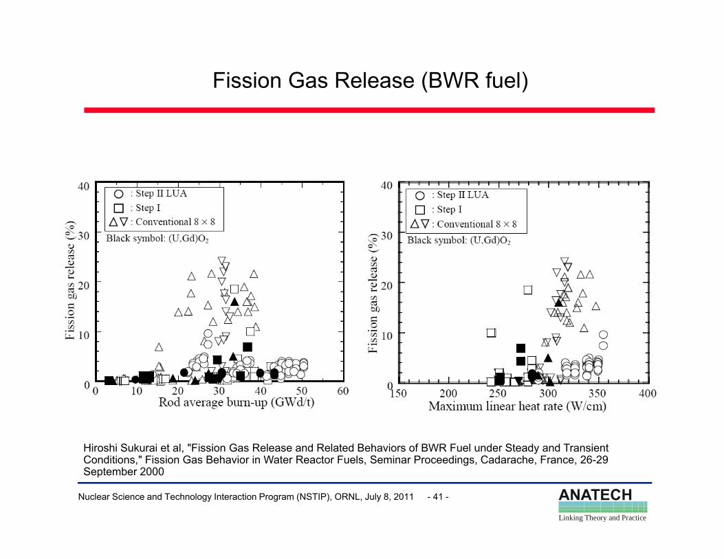
Fission Gas Release (BWR fuel)
Hiroshi Sukurai et al, "Fission Gas Release and Related Behaviors of BWR Fuel under Steady and Transient C diti " Fi i G B h i i W t R t F l S i P di C d h F 26 29
ANATECHLinking Theory and Practice
Nuclear Science and Technology Interaction Program (NSTIP), ORNL, July 8, 2011 - 41 -
Conditions," Fission Gas Behavior in Water Reactor Fuels, Seminar Proceedings, Cadarache, France, 26-29 September 2000
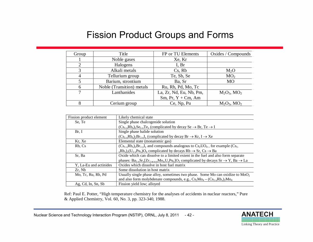
Fission Product Groups and Forms
Group Title FP or TU Elements Oxides / Compounds1 Noble gases Xe, Kr 2 Halogens I, Br 3 Alkali metals Cs, Rb M2O 4 Tellurium group Te Sb Se MO4 Tellurium group Te, Sb, Se MO25 Barium, strontium Ba, Sr MO 6 Noble (Transition) metals Ru, Rh, Pd, Mo, Tc 7 Lanthanides La, Zr, Nd, Eu, Nb, Pm,
Sm, Pr, Y + Cm, Am M2O3, MO2
8 Cerium group Ce, Np, Pu M2O3, MO2
Fission product element Likely chemical stateSe, Te Single phase chalcogenide solution
(Cs1-xRbx)2Se1-yTey (complicated by decay Se → Br, Te → I Br, I Single phase halide solution
(Cs Rb ) Br I (complicated by decay Br → Kr I → Xe(Cs1-xRbx)2Br1-yIy (complicated by decay Br → Kr, I → XeKr, Xe Elemental state (monatomic gas)Rb, Cs (Cs1-xRbx)2Br1-yIy and compounds analogous to Cs2UO4 , for example (Cs1-
xRbx)2(U1-yPuy)O4 complicated by decays Rb → Sr, Cs → Ba Sr, Ba Oxide which can dissolve to a limited extent in the fuel and also form separate
phases: Ba1-xSrx[Zr1-w-y-zMowUyPuz]O3 complicated by decays Sr → Y, Ba → La Y, La-Eu and actinides Oxides which dissolve in host fuel matrix ,Zr, Nb Some dissolution in host matrixMo, Tc, Ru, Rh, Pd Usually single phase alloy, sometimes two phase. Some Mo can oxidize to MoO2
and also form molybdenate compounds, e.g., Cs2Mo4 – (Cs1-xRbx)2Mo4 Ag, Cd, In, Sn, Sb Fission yield low; alloyed
Ref: Paul E. Potter, “High temperature chemistry for the analyses of accidents in nuclear reactors,” Pure & A li d Ch i l 60 3 323 340 1988
ANATECHLinking Theory and Practice
Nuclear Science and Technology Interaction Program (NSTIP), ORNL, July 8, 2011 - 42 -
& Applied Chemistry, Vol. 60, No. 3, pp. 323-340, 1988.
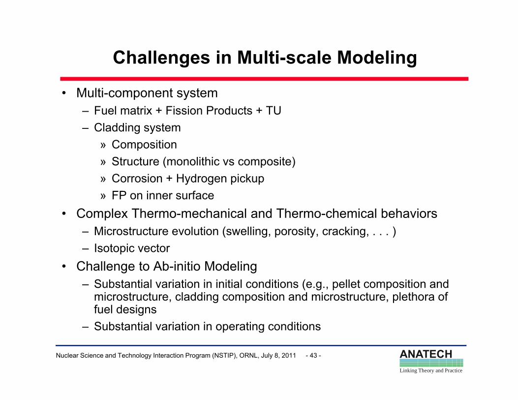
Challenges in Multi-scale Modeling
• Multi-component system– Fuel matrix + Fission Products + TU
Cl ddi t– Cladding system» Composition» Structure (monolithic vs composite)
C i H d i k» Corrosion + Hydrogen pickup» FP on inner surface
• Complex Thermo-mechanical and Thermo-chemical behaviors– Microstructure evolution (swelling, porosity, cracking, . . . )– Isotopic vector
• Challenge to Ab-initio Modeling– Substantial variation in initial conditions (e.g., pellet composition and
microstructure, cladding composition and microstructure, plethora of fuel designsSubstantial variation in operating conditions
ANATECHLinking Theory and Practice
Nuclear Science and Technology Interaction Program (NSTIP), ORNL, July 8, 2011 - 43 -
– Substantial variation in operating conditions
Conclusions
• Fuel Designs and Materials– Designs have evolved substantially over the last 4 decades– LWR Fuel Operation has evolved substantially in the last 4 decadesLWR Fuel Operation has evolved substantially in the last 4 decades
• Fuel Performance Codes– Engineering scale codes with 1-1/2 D mechanicsg g– Materials properties and behavioral models are empirical– FREY/FALCON unique 2D axisymmetric mechanics, but materials properties
and behavioral models are empirical
• Challenges in Modeling– Fuel-Cladding Gap, Relocation– PCIPCI – Fission Gas Release
• Substantial variations in Fuel Designs and Operation challenge Ab-initio
ANATECHLinking Theory and Practice
Nuclear Science and Technology Interaction Program (NSTIP), ORNL, July 8, 2011 - 44 -
g p gModeling