Embed Size (px)
Citation preview
145
Step Drills HSS
• Subland Drills with straight shank
• Subland Drills with taper shank
• Step Drills for Centre Holes
STE
P D
RIL
LS H
SS

146
147
Bright
Steam Tempered
Nitrided lands
TiN
TiCN
TiAlN
Bronze
List-No.:
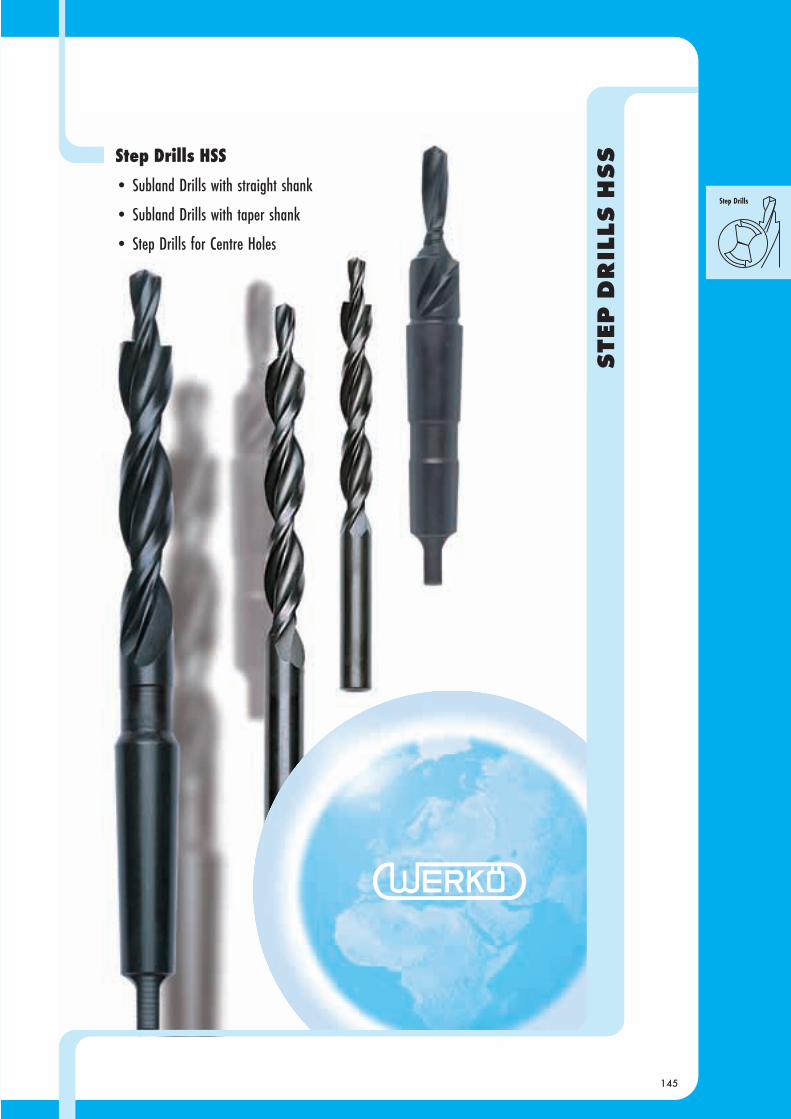
Standard
Type
Material
Ø mm:
Ø ins:
Surface
Web thinning
Catalogue page
Step Drills HSS
N - 90° N - 180° N - 90° N - 180° N N
HSS HSS HSS HSS HSS HSS
M3... M12 M3... M10 M5... M20 M5... M20 M6... M24 M6... M30
155 156 157 158 159 160
2527
18
2529
18
2537
18
2539
18
2515
18
2516
18
DIN 8374
DIN 8378
DIN 8376 DIN 8375
DIN 8379
DIN 8377 Factory Standard
Form D
Step Drills
for Centre Holes
Factory Standard
Form DS
with straight shank with taper shank
Subland Drills
< 550 < 180 E
500 - 850 150 - 250 E
< 800 < 240 E
800 - 1.000 240 - 300 E
< 750 < 220 E
750 - 950 220 - 280 E / Oil
950 - 1.200 280 - 350 Oil / E
< 700 < 200 E
700 - 850 200 - 250 E / Oil
850 - 1.200 250 - 350 Oil / E
700 - 850 200 - 250 E
850 - 1.000 250 - 300 Oil / E
700 - 850 200 - 250 E
850 - 1.000 250 - 300 Oil / E
600 - 800 180 - 240 E
800 - 1.200 240 - 350 Oil / E
700 - 1.100 200 - 320 Oil / E
< 1.250 < 370 Oil / E
< 1.550 < 450 Oil / E
500 - 800 150 - 240 Oil
450 - 700 130 - 200 Oil
500 - 800 150 - 240 Oil
<[55] Oil
< 1.200 < 350 Oil
< 240 E / A
< 300 E / A
< 800 < 240 Oil
800 - 1.200 240 - 350 Oil
< 400 < 120 E
< 600 < 180 E
< 600 < 180 E
< 450 < 130 E
< 400 < 120 E / A
< 600 < 180 E / Oil
< 600 < 180 E / Oil
< 600 < 180 E / Oil
600 - 850 180 - 250 Oil / E
< 800 < 240 E / Oil
800 - 1.200 240 - 300 Oil / E
E / A
A
Cutting depth
Material
Surface finish
Type
Straight shank DIN8374/8378 Right hand
DIN8376 Right hand
Taper shank WN Right hand
DIN8375/8379 Right hand
DIN8377 Right hand
Tensile strength Hardness Coolant
N/mm2 HB [HRC]Material Group Material examples (DIN EN ISO) Material examples (British Standard)
Structural steels S185; S235JRH; S275JR; (St 33 - St 44) BS 4360- 40 B; 43 B; (En 1)
E295; E335; E360; (St 50 - St 70) BS 4360- 50 C; 55 C; (En 2)
Free cutting steels 10 S 20; 11 SMnPb 30; 11 SMn 37 210 M 15, leaded
46 S 20; 60 S 20; 46 SPb 20 216 M 36, leaded
Case-hardening steels C 10; C 15; C 10 E; C 15 E 080 A 15; 040 A 10 (En 2 A); 045 M 10 (En 32 A)
15 CrNi 6 ; 38 Cr 4
16 MnCr 5; 20 MnCr 5; 25 MoCr 4 527 M 17; 590 M 17
Heat treatable steels C 22; C 35; C 22 E; C 30 E 070 M 20 (En 3); 080 M 30 (En 5)
C 45; C 45 E; C 60; 50 MnSi 4 080 M 46 (En 8); 080 M 50 (En 43 A),
41 Cr 4; 37 MnSi 4; 42 CrMo 4 640 A 35 (En 111 A),
Tool steels, cold working 102 Cr 6; 55 NiCrMoV 6 D2, D4, O1 (silver steel), P20
X 91 CrMoV 18; X 100 CrMoV 5-1
Tool steels, hot working 29 CrMoV 9; X 21 Cr 13 H10; H13; annealed HSS (M2, M3, M35, M42)
X 45 NiCrMo 4; 28 NiMo 17 H10; H13 quenched and tempered
Nitrided steels 34 CrAl 6 897 M 39
31 CrMoV 9; 31 CrMo 12 722 M 24
Spring steels 38 Si 6; 51 MnV 7; 67 SiCr 5 251 A 58 (En 45 A), 735 A 51 (En 47)
High alloyed special steels Hardox 400; XAR 400 Hardox 400; XAR 400
Hardox 500; XAR 500; Weldox 1100 Hardox 500; XAR 500; Weldox 1100
Stainless steels, austenitic X 20 Cr 13; X 5 CrNi 18-10; 304 S 31; 304 S 15 (En 58 E);
X 6 CrNiMoTi 17-12-2 320 S 33; 316 S 11
Heat-resisting steels X 10 CrSi 6; X 10 CrAl 7 303 S 31
X 10 CrAl 18; X 15 CrNiSi 20-12 309 S 24
Hardened steels
Special alloys Nimonic; Inconel; Monel; Hastelloy
Cast iron, spheroidal-graphite GG10 - 25; GGG35 - 50; GTW35; GTS55 BS 1452 grade 350; 400; W35-04; pearlitic
and malleable cast iron GG30 - 45; GGG60 - 70; GTW65; GTS70 BS 2789 grade 600/3; 700/2
Titanium and Titanium alloys Ti99,5; TiAl5Sn2,5; TiCu2
TiAl6Zr5; TiAl6V4; TiAl4Mo4Sn2,5;
Aluminium and Aluminium alloys Al99,5; AlMgSi1; AlMg1 1050A; 6082; LM0; LM1B
Al - cast alloys ≤10% Si G-AlSi5; G-AlSi6Cu4 LM2; LM4; LM5; LM10; LM16; LM21; LM22;
Al - cast alloys >10% Si G-AlSi12; G-AlSi12Cu LM6; LM12; LM13; LM20; LM28; LM30
Al - wrought alloys AlMgSiPb; AlCuSiMg; AlCuMgPb; AlMg7 6012; 2030;
Copper E-Cu; F-Cu; D-Cu; SE-Cu; SF-Cu; SD-Cu BS 2874: C101; C103; C106;
Brass, long chipping CuZn33; CuZn36Pb3 (Ms65 - Ms90) BS 2874: CZ107; CZ102;
Brass, short chipping CuZn39Pb2 (Ms58 - Ms63) BS 2874: CZ122; CZ128;
Bronze, short chipping CuSn7ZnPb; CuPb5Sn5
CuNi18Zn19Pb BS2874: NS113
Bronze, long chipping CuAl5; CuAl9Mn; CA101
CuAl11Ni Ampco 18 - 26
Thermoplastics PVC; Polyamid;Plexiglas; Novadur;
Duroplastics Bakelit; Pertinax; Resopal
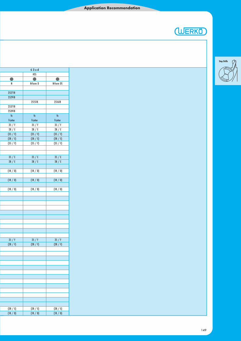
Application Recommendation for Step Drills HSS
Application Recommendation
148
Vc = average cutting speed (m/min)f-Letter = feed columnn = speed (r.p.m.)E = emulsionA = airOil = cutting oil
n = Vc * 1.000 / π / d Speed series: page 488
Cutting speed to choose suited for the biggest diameter, feedsuited for the smalles diameter!
Bright TiCN
Steam tempered TiAlN
Nitrided lands Bronze
TiN
Nominal diameter in mm 2,50 4,00 6,30 10,0 16,0 25,0 40,0 63,0
Letter
A 0,025 0,040 0,050 0,080 0,100 0,160 0,200 0,315
B 0,032 0,050 0,063 0,100 0,125 0,200 0,250 0,400
C 0,040 0,063 0,080 0,125 0,600 0,250 0,315 0,500
D 0,050 0,080 0,100 0,160 0,200 0,315 0,400 0,630
E 0,063 0,100 0,125 0,200 0,250 0,400 0,500 0,800
F 0,080 0,125 0,160 0,250 0,315 0,500 0,630 1,000
G 0,100 0,160 0,200 0,315 0,400 0,630 0,800 1,250
H 0,125 0,200 0,250 0,400 0,500 0,800 1,000 1,600
Feed column (mm/rev)
35 / F 35 / F 35 / F
28 / E 28 / E 28 / E
(35 / F) (35 / F) (35 / F)
(28 / E) (28 / E) (28 / E)
(35 / F) (35 / F) (35 / F)
35 / E 35 / E 35 / E
28 / E 28 / E 28 / E
(18 / D) (18 / D) (18 / D)
(18 / D) (18 / D) (18 / D)
(18 / D) (18 / D) (18 / D)
35 / F 35 / F 35 / F
(28 / F) (28 / F) (28 / F)
(28 / E) (28 / E) (28 / E)
(18 / D) (18 / D) (18 / D)
≤ 3 x dHSS
N N-Form D N-Form DS
252718
252918
251518 251618
253718
253918
Vc Vc Vc
f-Letter f-Letter f-Letter
Application Recommendation
149

150

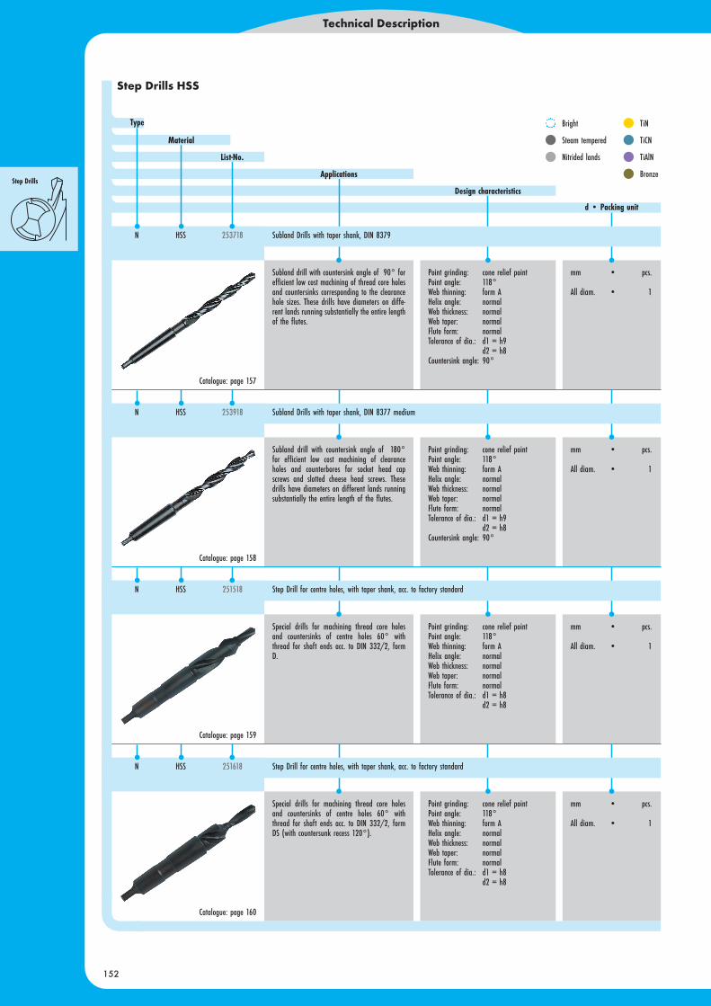
Subland drill with countersink angle of 90° forefficient low cost machining of clearance holesand countersinks for countersunk head screws.These drills have diameters on different landsrunning substantially the entire length of the flu-tes.
Point grinding: cone relief pointPoint angle: 118°Web thinning: form AHelix angle: normalWeb thickness: normalWeb taper: normalFlute form: normalTolerance of dia.: d1 = h9
d2 = h8Countersink angle: 90°
mm • pcs.
All diam. • 1
Subland drill with countersink angle of 180°for efficient low cost machining of clearanceholes and counterbores for socket head cap scr-ews and slotted cheese head screws. These drillshave diameters on different lands running sub-stantially the entire length of the flutes.
Point grinding: cone relief pointPoint angle: 118°Web thinning: form AHelix angle: normalWeb thickness: normalWeb taper: normalFlute form: normalTolerance of dia.: d1 = h9
d2 = h8Countersink angle: 90°
mm • pcs.
All diam. • 1
Subland drill with countersink angle of 90° forefficient low cost machining of thread core holesand countersinks corresponding to the clearancehole sizes. These drills have diameters on diffe-rent lands running substantially the entire lengthof the flutes.
Point grinding: cone relief pointPoint angle: 118°Web thinning: form AHelix angle: normalWeb thickness: normalWeb taper: normalFlute form: normalTolerance of dia.: d1 = h9
d2 = h8Countersink angle: 90°
mm • pcs.
All diam. • 1
Subland drill with countersink angle of 90° forefficient low cost machining of clearance holesand countersinks for countersunk head screws.These drills have diameters on different landsrunning substantially the entire length of the flu-tes.
Point grinding: cone relief pointPoint angle: 118°Web thinning: form AHelix angle: normalWeb thickness: normalWeb taper: normalFlute form: normalTolerance of dia.: d1 = h9
d2 = h8Countersink angle: 90°
mm • pcs.
All diam. • 1
Technical Description
151
Bright
Steam tempered
Nitrided lands
TiN
TiCN
TiAlN
Bronze
Step Drills HSS
Typ
Schneidstoff
Bestell-Nr.
Anwendungsbeispiele
Konstruktionsmerkmale
d • Verpackungseinheit
TLS 1000C HSS 233342 Spiralbohrer mit Zylinderschaft, kurz DIN 338
TLS 1000C HSS 233342 Spiralbohrer mit Zylinderschaft, kurz DIN 338
TLS 1000C HSS 233342 Spiralbohrer mit Zylinderschaft, kurz DIN 338
TLS 1000C HSS 233342 Spiralbohrer mit Zylinderschaft, kurz DIN 338
Catalogue: page 155
Catalogue: page 155
Catalogue: page 156
Catalogue: page 157
N HSS 253718 Subland Drills with taper shank, DIN 8375 medium
N HSS 252718 Subland Drills with straight shank, DIN 8378
N HSS 252918 Subland Drills with straight shank, DIN 8376 medium
d • Packing unit
Design characteristics
Applications
List-No.
Material
Type
N HSS 252718 Subland Drills with straight shank, DIN 8374 fine/medium
Technical Description
152
Subland drill with countersink angle of 90° forefficient low cost machining of thread core holesand countersinks corresponding to the clearancehole sizes. These drills have diameters on diffe-rent lands running substantially the entire lengthof the flutes.
Point grinding: cone relief pointPoint angle: 118°Web thinning: form AHelix angle: normalWeb thickness: normalWeb taper: normalFlute form: normalTolerance of dia.: d1 = h9
d2 = h8Countersink angle: 90°
mm • pcs.
All diam. • 1
Subland drill with countersink angle of 180°for efficient low cost machining of clearanceholes and counterbores for socket head capscrews and slotted cheese head screws. Thesedrills have diameters on different lands runningsubstantially the entire length of the flutes.
Point grinding: cone relief pointPoint angle: 118°Web thinning: form AHelix angle: normalWeb thickness: normalWeb taper: normalFlute form: normalTolerance of dia.: d1 = h9
d2 = h8Countersink angle: 90°
mm • pcs.
All diam. • 1
Special drills for machining thread core holesand countersinks of centre holes 60° withthread for shaft ends acc. to DIN 332/2, formD.
Point grinding: cone relief pointPoint angle: 118°Web thinning: form AHelix angle: normalWeb thickness: normalWeb taper: normalFlute form: normalTolerance of dia.: d1 = h8
d2 = h8
mm • pcs.
All diam. • 1
Special drills for machining thread core holesand countersinks of centre holes 60° withthread for shaft ends acc. to DIN 332/2, formDS (with countersunk recess 120°).
Point grinding: cone relief pointPoint angle: 118°Web thinning: form AHelix angle: normalWeb thickness: normalWeb taper: normalFlute form: normalTolerance of dia.: d1 = h8
d2 = h8
mm • pcs.
All diam. • 1
N HSS 251618 Step Drill for centre holes, with taper shank, acc. to factory standard
N HSS 253918 Subland Drills with taper shank, DIN 8377 medium
N HSS 251518 Step Drill for centre holes, with taper shank, acc. to factory standard
Bright
Steam tempered
Nitrided lands
TiN
TiCN
TiAlN
Bronze
Catalogue: page 157
Catalogue: page 158
Catalogue: page 159
Catalogue: page 160
d • Packing unit
Design characteristics
Applications
List-No.
Material
Type
Step Drills HSS
N HSS 253718 Subland Drills with taper shank, DIN 8379
Technical Description
153
Bright
Steam tempered
Nitrided lands
TiN
TiCN
TiAlN
Bronze
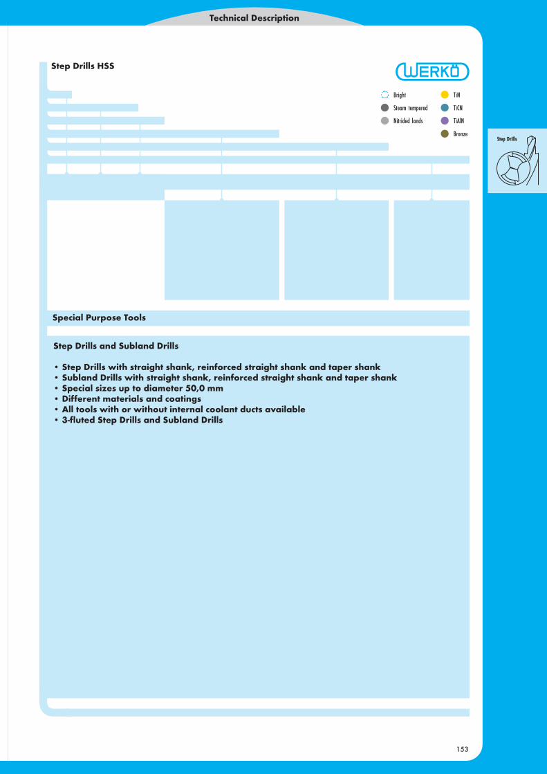
Step Drills HSS
Step Drills and Subland Drills
• Step Drills with straight shank, reinforced straight shank and taper shank• Subland Drills with straight shank, reinforced straight shank and taper shank• Special sizes up to diameter 50,0 mm• Different materials and coatings• All tools with or without internal coolant ducts available• 3-fluted Step Drills and Subland Drills
Special Purpose Tools

154
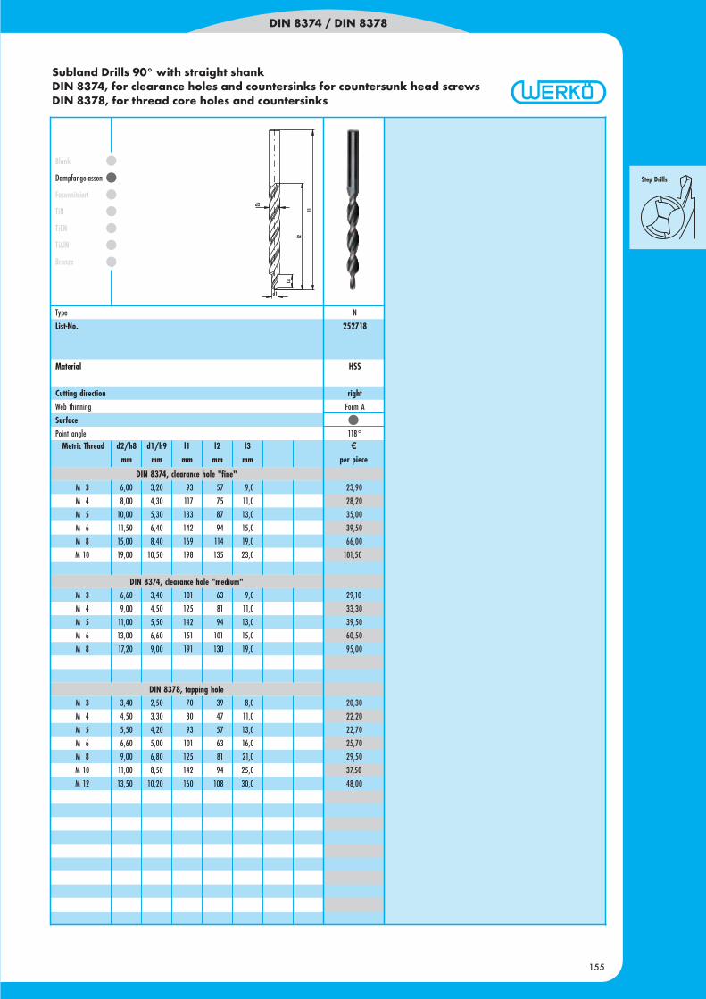
DIN 8374 / DIN 8378
155
Metric Thread d2/h8 d1/h9 l1 l2 l3 ¤mm mm mm mm mm per piece
23,90
28,20
35,00
39,50
66,00
101,50
29,10
33,30
39,50
60,50
95,00
20,30
22,20
22,70
25,70
29,50
37,50
48,00
Type N
List-No. 252718
Material HSS
Cutting direction rightWeb thinning Form A
SurfacePoint angle 118°
Blank
Dampfangelassen
Fasennitriert
TiN
TiCN
TiAlN
Bronze
DIN 8374, clearance hole "fine"M 3 6,00 3,20 93 57 9,0
M 4 8,00 4,30 117 75 11,0
M 5 10,00 5,30 133 87 13,0
M 6 11,50 6,40 142 94 15,0
M 8 15,00 8,40 169 114 19,0
M 10 19,00 10,50 198 135 23,0
DIN 8374, clearance hole "medium"M 3 6,60 3,40 101 63 9,0
M 4 9,00 4,50 125 81 11,0
M 5 11,00 5,50 142 94 13,0
M 6 13,00 6,60 151 101 15,0
M 8 17,20 9,00 191 130 19,0
DIN 8378, tapping holeM 3 3,40 2,50 70 39 8,0
M 4 4,50 3,30 80 47 11,0
M 5 5,50 4,20 93 57 13,0
M 6 6,60 5,00 101 63 16,0
M 8 9,00 6,80 125 81 21,0
M 10 11,00 8,50 142 94 25,0
M 12 13,50 10,20 160 108 30,0
Subland Drills 90° with straight shankDIN 8374, for clearance holes and countersinks for countersunk head screwsDIN 8378, for thread core holes and countersinks
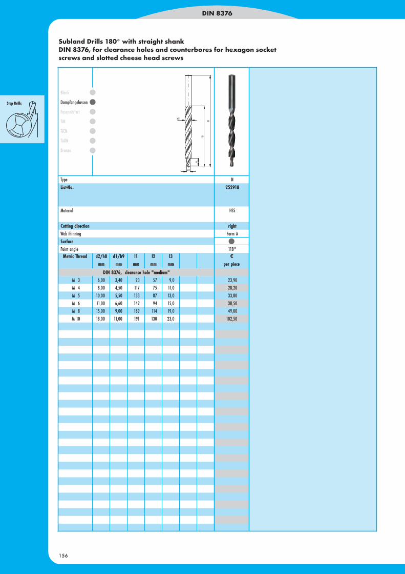
Subland Drills 180° with straight shankDIN 8376, for clearance holes and counterbores for hexagon socketscrews and slotted cheese head screws
DIN 8376
156
Metric Thread d2/h8 d1/h9 l1 l2 l3 ¤mm mm mm mm mm per piece
23,90
28,20
33,80
38,50
49,00
102,50
Blank
Dampfangelassen
Fasennitriert
TiN
TiCN
TiAlN
Bronze
DIN 8376, clearance hole "medium"M 3 6,00 3,40 93 57 9,0
M 4 8,00 4,50 117 75 11,0
M 5 10,00 5,50 133 87 13,0
M 6 11,00 6,60 142 94 15,0
M 8 15,00 9,00 169 114 19,0
M 10 18,00 11,00 191 130 23,0
Type N
List-No. 252918
Material HSS
Cutting direction rightWeb thinning Form A
SurfacePoint angle 118°
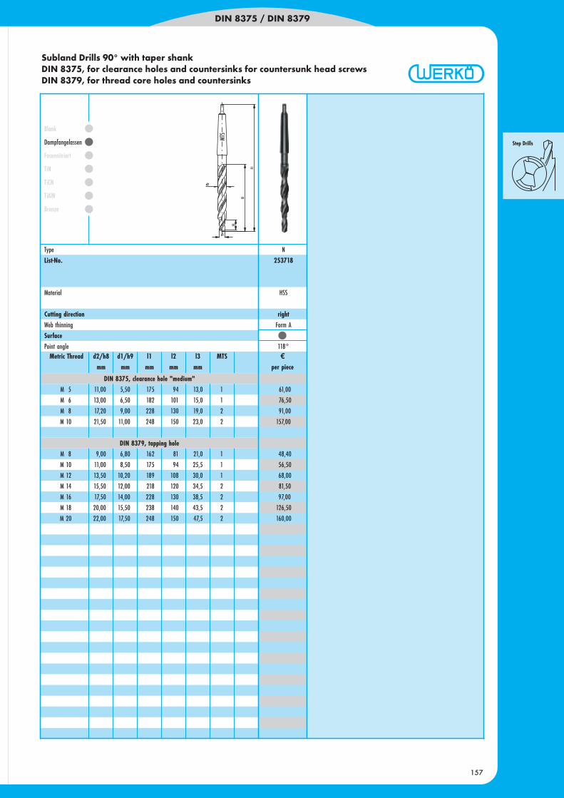
DIN 8375 / DIN 8379
157
61,00
76,50
91,00
157,00
48,40
56,50
68,00
81,50
97,00
126,50
160,00
Blank
Dampfangelassen
Fasennitriert
TiN
TiCN
TiAlN
Bronze
DIN 8375, clearance hole "medium"M 5 11,00 5,50 175 94 13,0 1
M 6 13,00 6,50 182 101 15,0 1
M 8 17,20 9,00 228 130 19,0 2
M 10 21,50 11,00 248 150 23,0 2
DIN 8379, tapping holeM 8 9,00 6,80 162 81 21,0 1
M 10 11,00 8,50 175 94 25,5 1
M 12 13,50 10,20 189 108 30,0 1
M 14 15,50 12,00 218 120 34,5 2
M 16 17,50 14,00 228 130 38,5 2
M 18 20,00 15,50 238 140 43,5 2
M 20 22,00 17,50 248 150 47,5 2
Type N
List-No. 253718
Material HSS
Cutting direction rightWeb thinning Form A
SurfacePoint angle 118°
Metric Thread d2/h8 d1/h9 l1 l2 l3 MTS ¤mm mm mm mm mm per piece
Subland Drills 90° with taper shankDIN 8375, for clearance holes and countersinks for countersunk head screwsDIN 8379, for thread core holes and countersinks
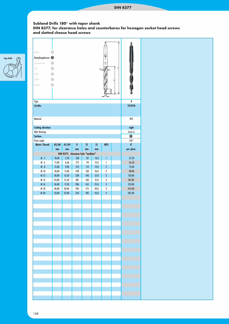
Subland Drills 180° with taper shankDIN 8377, for clearance holes and counterbores for hexagon socket head screwsand slotted cheese head screws
DIN 8377
158
55,70
56,50
74,00
98,00
120,00
181,00
210,00
245,00
285,00
Blank
Dampfangelassen
Fasennitriert
TiN
TiCN
TiAlN
Bronze
DIN 8377, clearance hole "medium"M 5 10,00 5,50 168 87 13,0 1
M 6 11,00 6,60 175 94 15,0 1
M 8 15,00 9,00 212 114 19,0 2
M 10 18,00 11,00 228 130 23,0 2
M 12 20,00 13,50 238 140 27,0 2
M 14 24,00 15,50 281 160 31,0 3
M 16 26,00 17,50 286 165 35,0 3
M 18 30,00 20,00 296 175 39,0 3
M 20 33,00 22,00 334 185 43,0 4
Metric Thread d2/h8 d1/h9 l1 l2 l3 MTS ¤mm mm mm mm mm per piece
Type N
List-No. 253918
Material HSS
Cutting direction rightWeb thinning Form A
SurfacePoint angle 118°
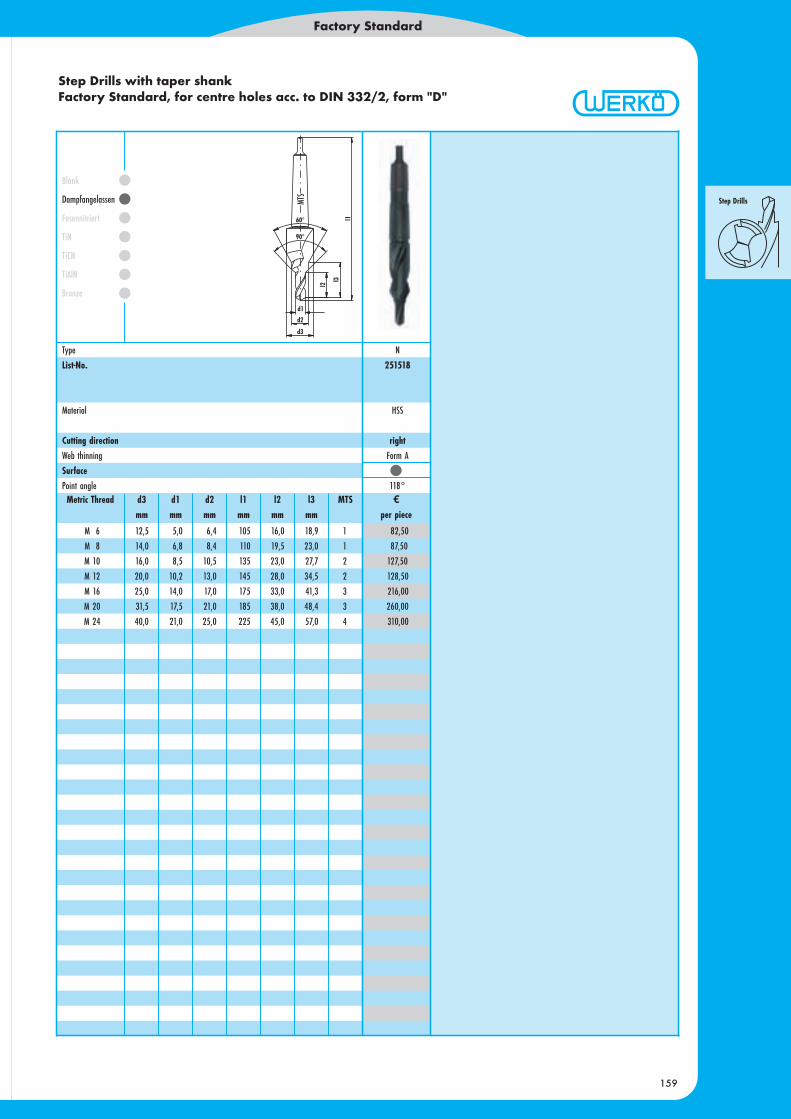
Step Drills with taper shankFactory Standard, for centre holes acc. to DIN 332/2, form "D"
Factory Standard
159
82,50
87,50
127,50
128,50
216,00
260,00
310,00
Blank
Dampfangelassen
Fasennitriert
TiN
TiCN
TiAlN
Bronze
M 6 12,5 5,0 6,4 105 16,0 18,9 1
M 8 14,0 6,8 8,4 110 19,5 23,0 1
M 10 16,0 8,5 10,5 135 23,0 27,7 2
M 12 20,0 10,2 13,0 145 28,0 34,5 2
M 16 25,0 14,0 17,0 175 33,0 41,3 3
M 20 31,5 17,5 21,0 185 38,0 48,4 3
M 24 40,0 21,0 25,0 225 45,0 57,0 4
Metric Thread d3 d1 d2 l1 l2 l3 MTS ¤mm mm mm mm mm mm per piece
Type N
List-No. 251518
Material HSS
Cutting direction rightWeb thinning Form A
SurfacePoint angle 118°
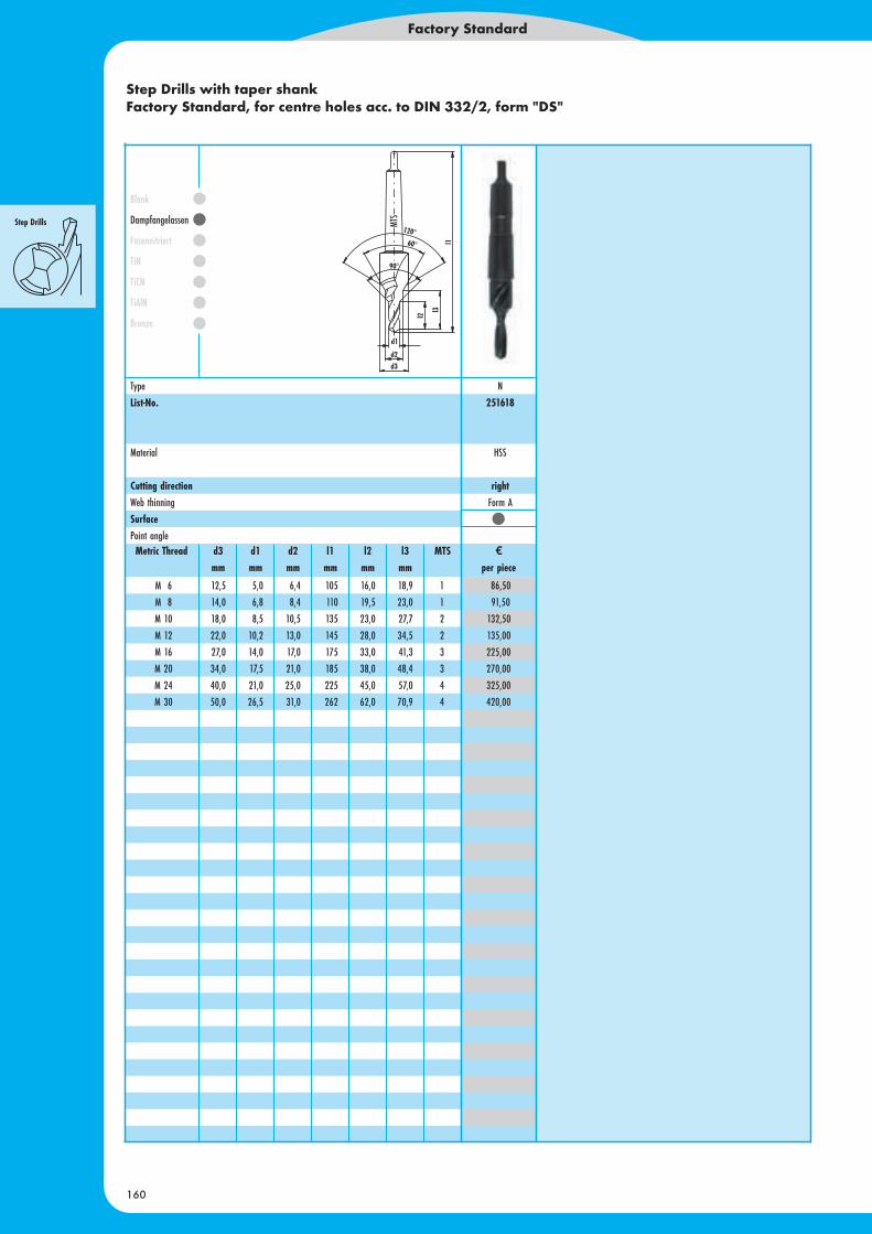
Step Drills with taper shankFactory Standard, for centre holes acc. to DIN 332/2, form "DS"
Factory Standard
160
86,50
91,50
132,50
135,00
225,00
270,00
325,00
420,00
Blank
Dampfangelassen
Fasennitriert
TiN
TiCN
TiAlN
Bronze
M 6 12,5 5,0 6,4 105 16,0 18,9 1
M 8 14,0 6,8 8,4 110 19,5 23,0 1
M 10 18,0 8,5 10,5 135 23,0 27,7 2
M 12 22,0 10,2 13,0 145 28,0 34,5 2
M 16 27,0 14,0 17,0 175 33,0 41,3 3
M 20 34,0 17,5 21,0 185 38,0 48,4 3
M 24 40,0 21,0 25,0 225 45,0 57,0 4
M 30 50,0 26,5 31,0 262 62,0 70,9 4
Type N
List-No. 251618
Material HSS
Cutting direction rightWeb thinning Form A
SurfacePoint angleMetric Thread d3 d1 d2 l1 l2 l3 MTS ¤
mm mm mm mm mm mm per piece