Embed Size (px)
Citation preview

Dimensioning part 1
with SolidWorks
ENGR 1182
SolidWorks 08

Today’s Objectives
Formal Drawing Components:
• Dimensioning with SolidWorks
SW08 Activity
SW08 Application

Formal Drawings
Formal Drawing
Components:
1. Extracted Drawings
• Extracted Views
• Detailed Features
• Title Block
2. Dimensions
• Size and Type of Features
Definition: Detailed multi-
view representations of a
finished part

Basic Dimensioning
Dimensioning is used to define an object so
that it could be manufactured and must:
Define the overall size of the part in all 3
dimensions.
Define the size and location of the
features of the part in all 3 dimensions.

Review Basic Dimensioning
.75
2
2
Overall
Size
Features
Size and
Location
.75
2
2
.25
1

Basic Dimensioning:
Arcs and Circles
.5
1 R1
.5
1 R1
Ø1
Overall
Size
Features
Size and
Location
OBJECT IS SYMMETRICAL
TOP TO BOTTOM
OBJECT IS SYMMETRICAL
TOP TO BOTTOM
1
WITHOUT THE SYMMETRY
NOTE PRESENT, THIS
DIMENSION WOULD BE
REQUIRED

When dimensioning objects with Center Marks it is
usually advantageous to establish the Center Marks
location early in the dimensioning process
Note that by dimensioning the
Center Mark offset early, it
becomes readily apparent that
by using it, in combination with
the radius (R1), the width of
the object is fully specified.

Review Baseline Vs. Chain Dimensioning
Baseline Dimensioning Chain Dimensioning
• There are many ways to use
dimensions to locate features.
• Chain
• Baseline
(Both techniques are acceptable, however
baseline dimensions are preferred.)

Review Dimensioning Guidelines

SolidWorks: Setup Dimensioning
Standards There are multiple dimensioning standards used in
manufacturing and technical drawings.
ANSI – EED preferred Standard
Go to Options Icon and click on Options
Open the
SolidWorks
options menu

SolidWorks: Setup Dimensioning
Standards ANSI – EED preferred Standard
Under Document Properties
• ANSI Modified listed as the Overall
drafting standard but this usually
often to be reset
• Reset System:
Switch to ISO, then hit OK
Repeat the sequence and switch it back
to ANSI Modified

Dimensioning in SolidWorks
Add Dimensions to:
Establish Overall Size
Add Dimensions to:
Features Size and Location
Recall the process we
used for Hand Drawings
In SolidWorks we need
to add 3 more steps to
the process
After creating the Extracted Drawing,
Complete the Title Block
Check for any missing Center Marks
and Center Lines
Check for Symmetry and add an
appropriate Note
We applied a limited set
of the Guidelines earlier
to simple Hand Drawings
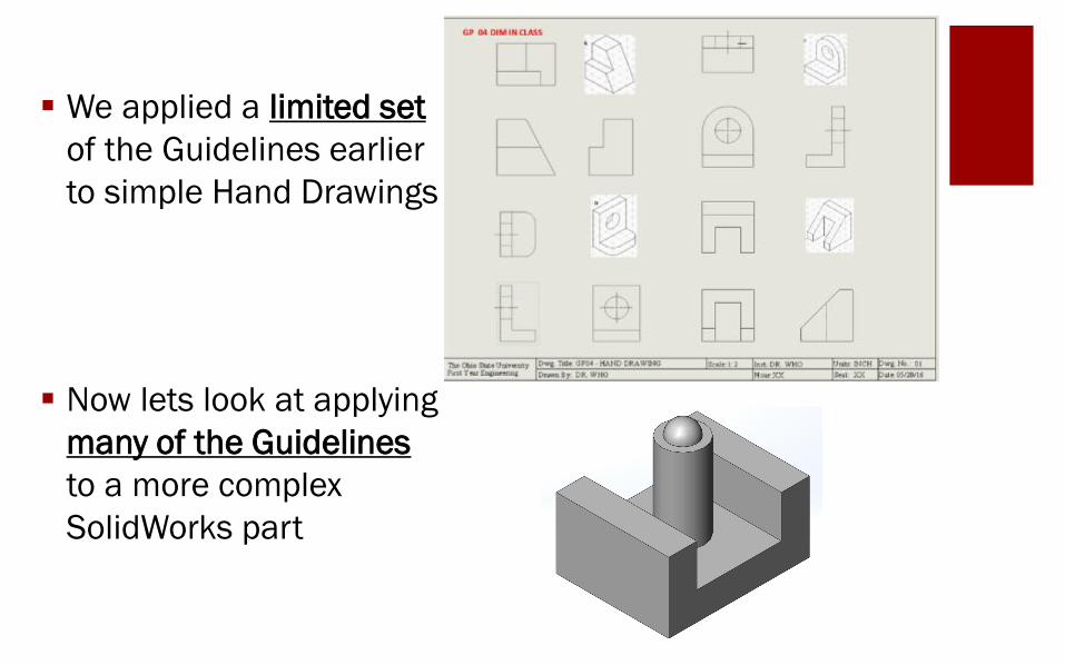
Now lets look at applying
many of the Guidelines
to a more complex
SolidWorks part

Add any missing Center Marks
(none) and Center Lines
Check for Symmetry and add note
Extracted SolidWorks Drawing
with completed Title Block
DIMENSION HEIGHT – STEP 1
Guideline 2- Characteristic View
Guideline 3 – DIM Between Views

DIMENSION WIDTH
DIMENSION DEPTH
Guideline 8- Radi ( R )
DIMENSION HEIGHT – STEP 2
Guideline 2- Characteristic View
Guideline 3 – DIM Between Views
SIZE FEATURE - CYLINDER
Guideline 9- Positive Cylinder
where appears as a Rectangle

SIZE FEATURE - SLOT
Guideline 2- Characteristic View
Guideline 3 – DIM Between Views
Without the SYMMETRY note
many more dimensions would be
required in the Right Side View.
We know the corresponding
element on the right also has a
depth of 2.0. Since the cylinder
has a diameter of 3.0, then the
total “gap” is equal to
[10 – 3.0 - 2* 2.0 = 3.0] and
each individual gap is equal to
[ 3.0 / 2 = 1.5 ] . Also the
location of the center of the
cylinder would have required 2
dimensions in the Top View
. So what appeared to be fairly
complicated dimensioning has
been greatly simplified!
Dimensioning is now complete!

SolidWorks: Adding Dimensions
Note that sometimes the Isometric
needs to be re-scaled to allow
adequate drawing space which
requires a NOTE.
Dimensions can be
added using the
“Smart Dimension”
feature under Annotation
Notes can be added to
reduce the number of
dimensions by stating
symmetry or identifying
multiple fillet radii

SolidWorks Dimensioning
Wrap Up
Basic Rules of Dimensioning
1. Complete Title Block
2. Check for Missing Center Marks and Center Lines
3. Check for Symmetry and add Note
4. Overall size in all 3 dimensions
5. Size and location of all features in all 3 dimensions
ACTIVITY SW08 :
Model part and create 2D Drawings
with all necessary formatting
(dimension in next class)

SolidWorks: Adding Dimensions (Activity)
Dimensions can be
added using the
“Smart Dimension”
feature under
“Annotation”
A SYMMETRY note
can be added using
A Note under
“Annotation”

Activity (SW08)
Open the SolidWorks file
associated with Activity located in
the Zip File under in Carmen and
add dimensions to the following 4
shapes. UnZip the folder using 7-
Zip Extract Here

Important Takeaways
Extracted drawings are used to show 3D parts as 2D drawings.
Titles blocks are used for identification and informative purposes.
Some Center Marks and Center Lines will need to be added
A Symmetry note may need to be added
Dimensioning is used to define an object, including the overall
size with 3 dimensions and the location and size of part features.

What’s Next?
Due Next Class: SW08 Application
Before next class, you will read about Dimensioning in detail,
Implementing Section Views and Working Drawings in SolidWorks
Take SolidWorks 9 Quiz on readings