Embed Size (px)
Citation preview

DIMENSIONINGDIMENSIONING EXPANSION VESSELSHEAT EXCHANGERHEAT EXCHANGER
Werner WeissAEE - Institute for Sustainable Technologies (AEE INTEC)A-8200 Gleisdorf, Feldgasse 19AUSTRIA

Monitoring Results – Collector TemperaturesMonitoring Results Collector Temperatures
System
120
140
T-Solar VL T_Solar RL T-Prozess
100
120
60
80
°C]
20
40
Tem
pera
tur[
°
020.9.06 0:00 21.9.06 0:00 22.9.06 0:00 23.9.06 0:00 24.9.06 0:00 25.9.06 0:00 26.9.06 0:00 27.9.06 0:00
T

Stagnation behaviour – Test lab
Test- und Versuchssystem mit eingezeichneten Messstellen
g
Test und Versuchssystem mit eingezeichneten Messstellen
Geplanter Aufbau des Versuchs- und Testsystems

Stagnation behaviour – Test lab
Test system setup and positions of the sensors
Stagnation behaviour Test lab

Stagnation behaviour – Test lab
Test system: collectors
Stagnation behaviour Test lab

Stagnation behaviour – Test labTest system: Overall system
Stagnation behaviour Test lab

Stagnation behaviour – Test labStagnation behaviour Test lab
Test system: Heat Exchangers and Expansion Vessels

Stagnation behaviour – In situ MonitoringStagnation behaviour In situ Monitoring

Stagnation behaviour – In situ Monitoring
Meßanlage Bauer
Stagnation behaviour In situ Monitoring
Vorlauf 10,23 m
Dachboden 9,01 m
T 14
T 13
T 8
T 10 T 11 T 7
T 6
T 12
T 15
Rückla f 5 91 m
3, 2 m3, 2 mT 9
T 5
T 4
T 3
T 2
T 1
T 16
Rücklauf 5,91 m
22 m² Brutto - Ost 22 m² Brutto - West
Kellerdecke 2,44 m M 1:100
M 1:50 Druckmessung 2,27 m
4,8 m³Energie-speicher
p-Rückp-Vor
T 18
T 21
d 1,45 m
1,05 m
p-AG Druckmessung 0,29 m
speicher
Ausdehnungs-gefäß
T 17
T 19
T 22
T 23dp-Rück
T 20
dp-Vor
BezugsniveauT 19

Stagnation behaviour – In situ Monitoring
Vorlauf 10 23 m138°C 138°C 138°C
Meßanlage Bauer, 10. 09. 1999 - 13:30Globalstrahlung: 858 W/m²
Stagnation behaviour In situ Monitoring
Vorlauf 10,23 m
Dachboden 9,01 m
3 23 2
138 C138°C
138 C
137°C137°C
138°C 137°C
138 C
137°C
151°C
150°C
149°C
139°C
EN12975
0= 0.8a1a=2.4 W/(m² K) Rücklauf 5,91 m
3, 2 m3, 2 m138°C
139°C
139°C
²a
a2a=0.015 W/(m² K²)22 m² Brutto - Ost 22 m² Brutto - West
Kellerdecke 2,44 m
1,45 m
M 1:100
M 1:50 2,39 bar 2,40 bar
121°C
98°C Druckmessung 2,27 m
4,8 m³Energie-speicher 1,45 m
1,05 m38°C39°C
34°C
45°C2,58 bar
Ausdehnungs-gefäß
Druckmessung 0,29 m
Bezugsniveau44°C

Stagnation behaviourStagnation behaviour
T1 Sam. 1 T2 Sam. 2 T3 Sam. 3 T4 Sam. 4 T5 Sam. 5Temperaturen
140
150
160
Sa Sa 3 Sa 3 Sa 5 Sa 5
T6 Sam. 6 T7 Sam. 7 T8 DB Vorl G1 Pumpe
Phase 5
120
130
140
C] Pha
se 1
90
100
110
Tem
pera
tur [
°
Phase 3
60
70
80
T
se 2
Phase 4
40
50
60
11 24 12 36 13 48 15 00 1612
Pha
s
11:24 12:36 13:48 15:00 16:12Zeit

Stagnation behaviourStagnation behaviour
Druck3P Rücklauf P Vorlauf P Ausdehnungsgefäß Pumpe
2,5
Pha
se 2
Phase 5
1 5
2
Dru
ck [b
ar]
Pha
se 1
1
1,5
Phase 3
Phase 4
0,511:24 12:36 13:48 15:00 16:12
Zeit

Collector with bad emptying behaviourCollector with bad emptying behaviour
Kollektorverschaltung mit ungünstigem Entleerungsverhalten:
StagnationszustandKollektor im EN12975
0= 0.8a1a=2.4 W/(m² K)
Dampfbildung im KollektorStagnationszustandKollektor im
Normalbetrieb
aa2a=0.015 W/(m² K²)

Collector with good emptying behaviourCollector with good emptying behaviour
Kollektor im Normalbetrieb Dampfbildung im Kollektor
Stagnationszustand
EN12975
0= 0.8a1a=2.4 W/(m² K)aa2a=0.015 W/(m² K²)

HYDRAULIC SCHEME OF A SOLAR HOT WATER SYSTEMU C SC O SO O S S
6
1 circulation pumpcollector area
thermometer and pressure gaugelock valve
gravity brakecirculation pump
432
hot water3bar
°C/bar °C
5
escape valvethermometer
pressure relief valvethermometer and pressure gauge
7654
°C3
5
74
fill and empty valve
expansion tankthermometer
9
87
tankstorage1
22
10
8
cold water
10

EXPANSION VESSELEXPANSION VESSEL

EXPANSION VESSELEXPANSION VESSEL
correct wrong

EXPANSION VESSELEXPANSION VESSEL

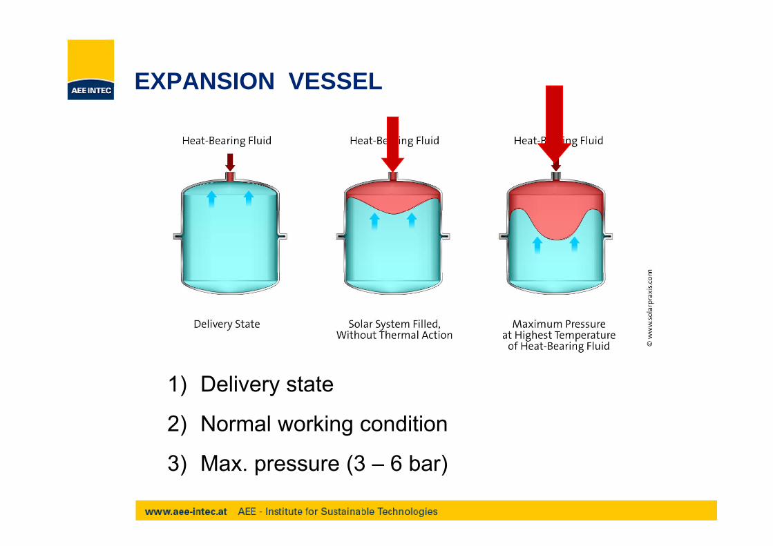
Mode of operationMode of operation
In order to keep the increase in pressure in all cases of operation at least 20% below the responding pressure of the security valve the expansion vessel h t t ihas to contain
1. the expansion volume of the heat transfer fluid2. the overall vapour volume (VD) at the state of
stagnation

General - MEVGeneral MEV
Adjustment of the Nitrogen-pre-pressure prior to the installation
Annual check of the pressure
Hanging installation with not insulted copper pipe
Installation before the pump and after the non-return valve
Membrane has to be resistant against glycol (anti-freeze fluid)
EXPANSION VESSELEXPANSION VESSEL
1) Delivery state
2) Normal working condition
3) M (3 6 b )3) Max. pressure (3 – 6 bar)

Terms for dimensioningTerms for dimensioning
Efficiency (Nutzeffekt) NEfficiency (Nutzeffekt) NCapacity of the MEV, which can be used without damage (over expansion) of the
bmembrane
Primary pressure in the vessel PPrimary pressure in the vessel P0Static height of the system plus 0.5 - 1 bar over pressure at the highest point of the
tsystem
Primary fluid (Gefäßvorlage) VPrimary fluid (Gefäßvorlage) VVReserve of fluid in case of a slight loss of pressure during air release
max. temperature at the membrane: 90°C

DimensioningDimensioning
Difference pressure Pdiff [bar]Hdiff = HMEV – HSV [m]
81,9HP kaltdiff
Hdiff HMEV HSV [m]ρ Density of the heat transfer fluid [kg/m³] 000.100
Pdiff
MEV Efficiency N [-]Pe = Pressure of the system [bar]P0 = Primary pressure in the MEV [bar] 1PP
9,0)1P(
1PPN
0diffe
0
Coefficient of expansion n [1] 0901kalt
1PP diffe
MEV Nominal volume VN [l]V = max volume of vapour [l]
09,01warm
kaltn
VD = max. volume of vapour [l]VG = Total volume of the heat transfer fuid [l]VV = Primary fluid (Gefäßvorlage) [l]
NVVnV
V DVGN

Calculation of the Primary FluidCalculation of the Primary Fluid
TT
Vmax
maxKKV TT
TTVV
VV Primary fluid [l]VK Volume of the collector [l]TK Temperature of the collector fluid at the expansion vessel [°C]T Origin temperature of the primary fluid in the MEV [°C]TV Origin temperature of the primary fluid in the MEV [ C]Tmax Max. permissible temperature in the MEV [°C] z.B. 90 °
Result: The volume of the primary fluid should correspond to the volume of the collector.correspond to the volume of the collector.

Example of calculationExample of calculation
Conditions:
· 10 m² collector area
· flow pipe VL: 15 m Cu pipe 18x1
ret rn pipe V 15 m C pipe 18 1· return pipe VL: 15 m Cu pipe 18x1
· safety valve: 6 bar
· pressure of the system: 2.5 bar
· primary pressure in the expansion vessel: 2 0 barprimary pressure in the expansion vessel: 2.0 bar

1st step : volume of the expansion vessel1 step : volume of the expansion vessel
VVnVV DVG
NVN
MEV nominal volume VN litreV maximum vapour volume litreVD maximum vapour volume litreVG total volume of the heat transfer fluid litre
VV primary fluid litre
N MEV efficiency
n coefficient of expansion of the heat transfer fluid

2nd step: Calculation of the MEV efficiency2 step: Calculation of the MEV efficiency
)1( P9.0
)1(1 0
diffePPP
N1
diffe PP
N
N MEV efficiencyPe nominal pressure of safety valve barp yP0 primary pressure bar

3rd step: Calculation of the MEV efficiency3 step: Calculation of the MEV efficiency
81.9 colddiffH
P000,100
diffP
Pdiff pressure difference barHdiff HMEV–HSV mdiff MEV SV
r density of the heat transfer fluid kg/m³ ~1051 kg/m³

3rd step: Calculation of the MEV efficiency3 step: Calculation of the MEV efficiency
barPdiff 052.0000100
81.910515.0
diff 000,100
Pdiff pressure difference barHdiff HMEV–HSV mdiff MEV SV
r density of the heat transfer fluid kg/m³ ~1051 kg/m³

3rd step: Calculation of the MEV efficiency3 step: Calculation of the MEV efficiency
)102()1( P
43.01052084
9.0)10.2(1052.08.4
19.0
)1(1 0
d ff
diffe
PP
PPPN
1052.08.41 diffe PP
Pe = nominal pressure of safety valve – tolerance of respond (20 %)
P = 6 bar – 20 % = 4 8 barPe 6 bar 20 % 4.8 bar
Pressure difference Pdiff = 0.052 bar
Nominal pressure of safety valve P = 4 8 barNominal pressure of safety valve Pe = 4.8 bar
Po = 2.0 bar

4th step: Calculation of the heat transfer fluid4 step: Calculation of the heat transfer fluid
V V V V litVG = Vpipe+ Vcoll + Vheat exchanger litre
Factor of expansion n
ld 99.01hot
coldn
0.45 l/ m²
160 2 5.120.25.43004
16.0
GV
4

5th step: Calculation of the primary fluid VV5 step: Calculation of the primary fluid VV
The volume of the primary fluid is more orThe volume of the primary fluid is more orless equivalent to the volume of the collector.
->VV = Vcoll = 4.5 litre

6th step: Calculation of the volume of vapour VD6 step: Calculation of the volume of vapour VD
VD = Vcoll + Vpipe-vapor litre
V ll = 4 5 litreVcoll 4.5 litre
Calculation of the volume of vapour in the pipesCalculation of the volume of vapour in the pipes
Maximum vapour power = 10 m² * 50 W/m² = 500 W
Vapour Power:Vapour Power:
Good draining collectors: 50 W/m²
Bad draining collector: 120 W/m²

6th step: Calculation of the volume of vapour VD6 step: Calculation of the volume of vapour VD
Calculation of the reach of the vapour in the solarpipes Vpipe-vapor (calculation through the thermal powerloss of the pipes):
Vorlauf 10,23 m138°C138°C
138°C
137°C138°C 137°C
138°C
151°C
Meßanlage Bauer, 10. 09. 1999 - 13:30Globalstrahlung: 858 W/m²
Dachboden 9,01 m
Rücklauf 5,91 m
Kellerdecke 2,44 m
3, 2 m3, 2 m
M 1:100
M 1:50
137°C137 C
137°C
150°C
149°C
139°C
138°C
139°C
139°C
2,39 bar 2,40 bar
22 m² Brutto - Ost 22 m² Brutto - West
thermal power loss of the pipe: 25 W/m1,45 m
1,05 m
Bezugsniveau
M 1:50 , , 0 ba
121°C
38°C
98°C
39°C
34°C
45°C2,58 bar
Druckmessung 2,27 m
4,8 m³Energie-speicher
Ausdehnungs-gefäß
Druckmessung 0,29 m
44°C
(reach of vapour in the pipe) = (max. vapour power)/(thermal power loss of the pipe per meter of pipe)per meter of pipe)
(reach of vapour in the pipe) = 500/25 = 20 meter 16 C i16er Cu pipe

6th step: Calculation of the volume of vapour VD6 step: Calculation of the volume of vapour VD
0420016.0 2
V 0.4200
4vapourpipeV
VD = 4.5 + 4.0 = 8.5 litre

6th step: Volume of the expansion vessel6 step: Volume of the expansion vessel
litreVVnVV DVG 8325.85.409.05.12
litre
NVN 8.32
43.0

Rule of ThumbRule of Thumb
Nominal volume of expansion vessel [ltr.] = collector area x 3.5
VN = a ll x 3 5VN acoll x 3.5
VN = 10 x 3.5 = 35 litre

Heat ExchangerHeat Exchanger

Flat plate heat exchangerFlat plate heat exchanger
Possibility of high pressures at operationPossibility of high pressures at operation
Principle of counter current
The high grades of turbulence leads to a self cleaning effect andsubsequently to a minimization of costs and a longer lifetimesubsequently to a minimization of costs and a longer lifetime
One plate heat exchanger can be used to load more than onep gheat storage tank
Disadvantages:
Like at all other external heat exchangers an additional pump isnecessary on the secondary side of the heat exchanger

Flat plate heat exchangerFlat plate heat exchanger
They are very compact compared with ordinary coil heatexchangers. They save about 85 to 90 % in volume and weight.
Maximum exploitation of the material: the capacity is 25 % higher asthe capacity of screwed plate heat exchangers The capacity is 10the capacity of screwed plate heat exchangers. The capacity is 10times higher as the capacity of coil heat exchangers.
Less use of energy because of a better heat transfer coefficient andsubsequently a better temperature difference
Heat transfer still at a temperature difference of 1 K

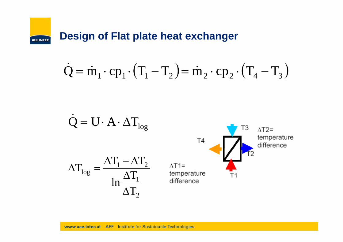
Design of Flat plate heat exchangerDesign of Flat plate heat exchanger
Temperature difference of a heat exchanger shown in a -T-diagramTemperature difference of a heat exchanger shown in a T diagram
T1T1m1
T2 T4
T2
T3
T2m2
Q
Design of Flat plate heat exchangerDesign of Flat plate heat exchanger
Q 34222111 TTcpmTTcpmQ
TAUQ logTAUQ
21log T
TTT
2
1
TTln

Design of Flat plate heat exchangerDesign of Flat plate heat exchanger
transferred power WQ transferred power W
mass flow per second kg/s
ifi h t it kJ/k K
Q21 m,m
cp1,cp2 specific heat capacity kJ/kgK
Ti temperature of the media °C
U heat transmission coefficient of the heat exchangerW/m²K
A heat transfer area m²A heat transfer area m²
DTlog logarithmic temperature difference K

Design of Flat plate heat exchangerDesign of Flat plate heat exchanger
Plate heat exchangers reach u values between 1000 and 2000Plate heat exchangers reach u-values between 1000 and 2000W/m²K (high power, low volume). Table 1 gives the necessaryvalues in order to design a heat exchanger.
Data for design of heat exchangers Primary circuit Secondary circuit
Media propylenglycol/water water
g g
Concentration of the fluid % 40 0
Temperature at entrance °C 65 25
Temperature at exit °C 32 60
Mass flow kg/s 0.25 – * *results from assumed data

Design of Flat plate heat exchangerDesign of Flat plate heat exchanger

Design of plate heat exchangerDesign of plate heat exchanger

Design of coil heat exchangersDesign of coil heat exchangers
Smooth pipe heat exchanger:
approx. 0.2 m² heat exchanger surface per m² collector area
Finned tubes heat exchanger:
approx. 0.3 – 0.4 m² heat exchanger surface per m² collector area

Design of coil heat exchangersDesign of coil heat exchangers

General rules of thumbGeneral rules of thumb
Collector Area
1 m² collector area per person (bed, shower)
Storage CapacityStorage Capacity
70 litre storage capacity / m² collector area
Heat Exchanger
0 2 ² / ² ll t f th t b HX0.2 m² / m² collector area for smooth tube HX
0.3 – 0.4 m² / m² collector area for finned tube HX
Expansion Vessel
VN = collector area x 3.5