Embed Size (px)
Citation preview
M A N U A L
Digitale three-phase Servo Amplifier DS-400.2
for EC/AC-Servo Motors
Industrie Elektronik G m b H
Hans-Paul-Kaysser-Staße 1 71397 Leutenbach-Nellmersbach Edition / Version Tel.: 07195 / 92 83 – 0 Fax: 07915 / 92 83 - 29 04/2013 V 05 [email protected] www.unitek-online.com

1 DS 400.2
Basic information
1 Contents 2 Basic information ....................................................................................................................... 3
2.1 History ................................................................................................................................ 3
2.2 Further UNITEK products ................................................................................................... 3
2.3 Engineering instructions (MANUAL) .................................................................................. 3
2.4 Validity ................................................................................................................................ 4
2.5 Designations and symbols .................................................................................................. 4
2.6 Scope of delivery ................................................................................................................ 4
2.7 General product information ............................................................................................. 5
2.8 Application/build/features ................................................................................................. 6
2.9 Safety regulations ............................................................................................................... 8
2.10 Commissioning ................................................................................................................. 10
2.11 Safety advices ................................................................................................................... 11
2.12 Intended applications ....................................................................................................... 12
2.13 Regulations and guidelines .............................................................................................. 13
2.14 Risks .................................................................................................................................. 14
2.15 Technical data .................................................................................................................. 15
3 Mechanical Installation ............................................................................................................ 18
3.1 Important advices ............................................................................................................ 18
3.2 Dimensions DS 405 – DS 420 ............................................................................................ 19
3.3 Dimensions - accessories.................................................................................................. 20
3.4 Installation ........................................................................................................................ 21
4 Electrical installation ................................................................................................................ 22
4.1 Important advice .............................................................................................................. 22
4.2 Circuit diagram ................................................................................................................. 23
4.3 Connection diagram ......................................................................................................... 25
4.4 Connections DS405.2, DS412.2, DS420.2 ......................................................................... 26
4.5 Connectors DS405.2/DS412.2/DS420.2 ......................................................................... 27
4.6 EMC .................................................................................................................................. 28
4.7 Mains connection ............................................................................................................. 29
4.8 Pre-charging ..................................................................................................................... 31
4.9 Auxiliary voltage connection ............................................................................................ 32
4.10 Motor connection ............................................................................................................ 33
4.11 Ballast circuit DS405 / DS412 / DS420 ............................................................................. 34
4.12 Ballast – dimensioning ..................................................................................................... 35
5 Control connection ................................................................................................................... 37
5.1 Digital input ...................................................................................................................... 37
5.2 Safety input RFE (rotating field enable) Stopp-Class 0 ..................................................... 38
Basic information
DS 400.2 2
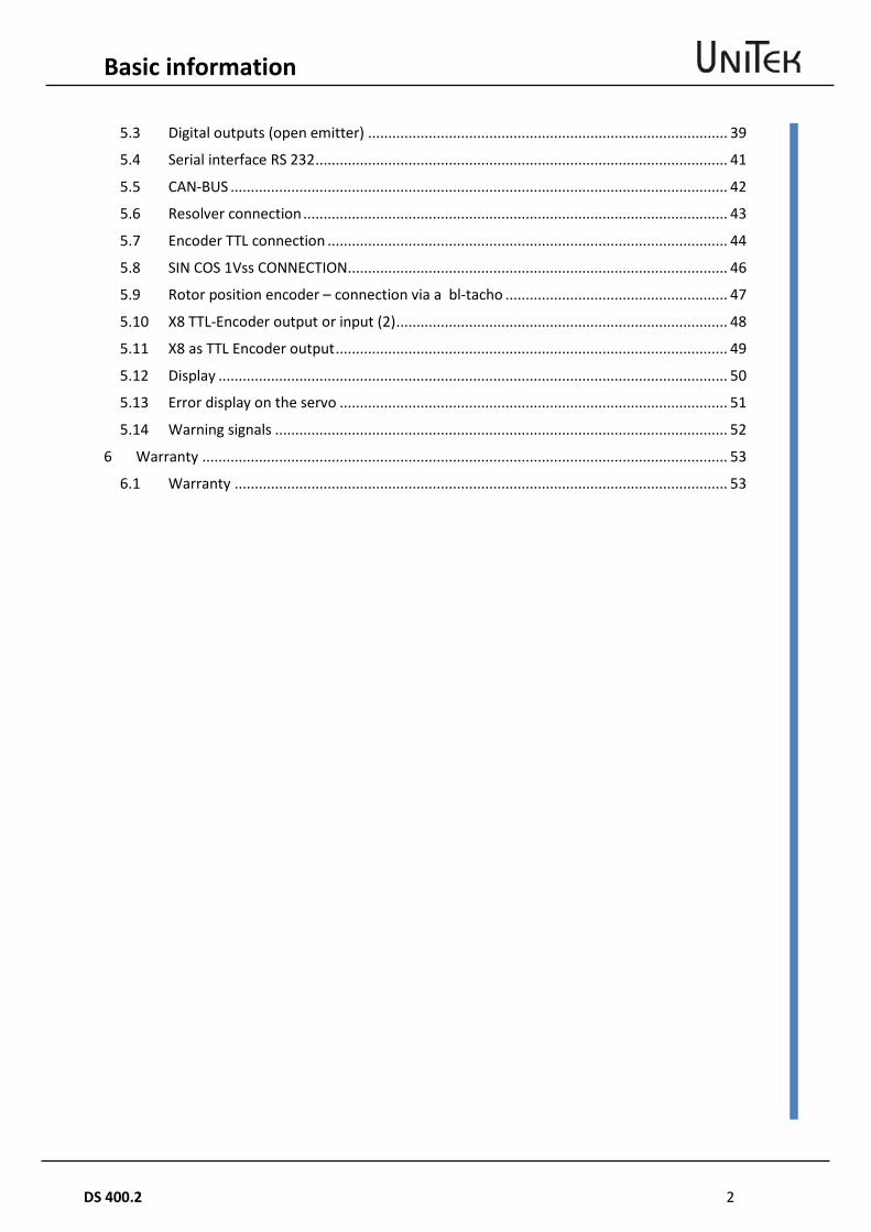
5.3 Digital outputs (open emitter) ......................................................................................... 39
5.4 Serial interface RS 232 ...................................................................................................... 41
5.5 CAN-BUS ........................................................................................................................... 42
5.6 Resolver connection ......................................................................................................... 43
5.7 Encoder TTL connection ................................................................................................... 44
5.8 SIN COS 1Vss CONNECTION .............................................................................................. 46
5.9 Rotor position encoder – connection via a bl-tacho ....................................................... 47
5.10 X8 TTL-Encoder output or input (2) .................................................................................. 48
5.11 X8 as TTL Encoder output ................................................................................................. 49
5.12 Display .............................................................................................................................. 50
5.13 Error display on the servo ................................................................................................ 51
5.14 Warning signals ................................................................................................................ 52
6 Warranty .................................................................................................................................. 53
6.1 Warranty .......................................................................................................................... 53
3 DS 400.2
Basic information
His
tory
2 Basic information
2.1 History
Version Modification Date 04/2013 V05 new English version 19.12.2103 04/2013 V05 drawing news, fault list
2.2 Further UNITEK products
Digital servo-amplifiers for small power values >>> UNITEK DS205, DS403,
DPCxx Analog three-phase servo-amplifiers TVD3, TVD6, AS
>>> UNITEK Series
Analog dc servo-amplifiers TV3, TV6, TVQ6
>>> UNITEK Series
Thyristor current converters 1Q, 4Q, Servo
>>> UNITEK Series Classic 200W to 800kW
DC and ac servo-amplifiers for battery operation A2, A3, D3
Series BAMO
Analog and digital Series BAMOBIL Series BAMOCAR
2.3 Engineering instructions (MANUAL)
1. MANUAL DS xxx Hardware 2. MANUAL NDrive2 Software 3. MANUAL DS, DPC Commissioning -
Troubleshooting Use all three MANUALs for the engineering, the installation, and the commissioning! CD (UNITEK-DOKU-SOFT) supplied with the delivery of the units. Online available as download version on the UNITEK website (www.unitek-online.de or www.unitek-online.eu). The hardware MANUAL comprises warning and safety advices, explanations of standards, mechanical and electrical installation advices. The MANUAL must be available for all persons who are concerned with the unit.

Basic information
DS 400.2 4
Valid
ity
2.4 Validity
Hardware state: Firmware state:
2.5 Designations and symbols
Unit DS xxx (BDM)
User: Manufacturers or operators of machines or installations in the industrial sector (B2B, secondary environment)
Manufacturer: UNITEK Industrie Elektronik GmbH
Dealer:
Caution - Danger to life! High voltage
Warning! Important
Dangerous electric fields
2.6 Scope of delivery
Divece DS405-x, DS412-x or DS420-x documentation DS400, NDrive, CD Unitek-Docu-Soft Connector plug Phönix 10pin. and 11pin. D-connector X7 15pin., X8 9pin In the shipping container Not in the delivery D-connectorr X9, X10 9pin.
5 DS 400.2
Basic information
Gen
eral
pro
duct
info
rmat
ion 2.7 General product information
The digital 3-phase current servo amplifiers DS/DPC xxx as component (BDM) in combination with the synchronous servo motor (EC motor) or the asynchronous servo motor (ac motor) provide a drive solution (PDS) free of maintenance and with a wide dynamic control range. The drive displays the well-known good control characteristics of dc drives without the disadvantages of the carbon brushes' wear and the commutation limits. For synchronous motors the generated heat in the motor only occurs in the stator, the rotor remains cold. The motors can easily be cooled via the surface (efficiency up to 96%). The physical characteristics correspond to those of dc motors, i.e., the current is proportional to the torque and the voltage is proportional to the speed. The speed is steadily controlled up to the current limit (max. torque. In case of an overload the speed drops and the current remains constant. The speed/torque characteristic is rectangular. Current, speed, and position are precisely measured. The field frequency is not controllable, it is automatically adjusted. The rotor moment of inertia is notably smaller and the limiting performance is higher which results in up to 5 times higher acceleration values. Asynchronous servo motors are less expensive and do not require solenoids in the rotor. The control characteristics are very good due to the space-vector control, the performance and the efficiency are lower. Due to the heated rotor it is necessary to use a motor fan for large control ranges. The EC and ac motors have the protection rating IP65. The motor voltages and the motor currents are sinusoidal. A maximum motor efficiency is achieved by means of a compensating current control. DS/DPCxx drives can be used as single-axis position amplifiers or torque or speed amplifiers. The position and speed actual value is generated in the encoder unit (resolver, incremental, or SIN/COS encoder). The encoder pulses are emitted from the amplifier for a superordinate PLC/CNC control. The control circuits of current, speed, and position are PID controllers which are easy to program. They can be programmed by means of the PC Software NDrive2. The communication with superordinate controls is effected by means of BUS systems (standard CAN-BUS, RS232) or by analogue interfaces. Note: For dc, ac, or EC servo amplifiers which are supplied by a bus circuit, it must be checked that the energy is fed back into the bus during brake operation (lift drives, winding machines, great centrifugal masses). An internal or possibly external ballast resistor is necessary.
Basic information
DS 400.2 6
Appl
icat
ion/
build
/fea
ture
s 2.8 Application/build/features
Application in machines and installations for all types of industrial use with a drive power of 13.5kW under hard application conditions especially as 4Q-servo-drive - highly dynamic acceleration and braking cycles - a wide control range - a high efficiency - small motor dimensions - a uniform, accurate and smooth running For speed or torque control or combined speed/torque control incorporated within or independent of position control loops. Suitable for: Machines and installations as well as component inserting machines, testing machines, sheet-metal working machines, machine tools, plastic working machines, assembly machines, knitting and sewing machines, textile working machines, grinding machines, wood and stone working machines, metal working machines, food processing machines, robots and handling systems, conveyors, extruders, calenders, and many other machines and installations for industrial applications. Build: - Robust units for switch cabinet mounting, steel housing, according to the VDE, DIN and EC regulations, protection rating IP20, VGB4 - Standard digital control electronics - Power electronics of 5 and 20A (S1 operation) - Power input voltage 30V~ to 480V~ (40V= to 500V=) - Independent 24V chopper power supply unit for the internal auxiliary voltages Galvanic isolation - between the housing and all electric parts - between the auxiliary voltage connection and the power section and the control electronics - between the power section and the control electronics - between the control electronics and the logic inputs/logic outputs The distance of air gaps and leakage paths adhere to the EU standards. Components used: - completely isolated IGBT power semi-conductors, comfortably over-dimensioned - only components customary in trade and industrially standardised are used - SMD equipment - LED displays , 7-segment displays
7 DS 400.2
Basic information
Appl
icat
ion/
build
/fea
ture
s Features: EMC protected steel housing Shock and vibration-proof build Direct mains connection 230V~ to 480V~ Independent auxiliary voltage connection 24V= Digital interfaces RS232, CAN-BUS (further option) Analog inputs, programmable differential inputs Digital inputs/outputs, programmable, optically de-coupled Output for brake 24V/3A with load watchdog logic for enable and the output stage switch, emergency stop function, safety BTB ready for operation, solid state relay Position, speed and torque control Encoder systems: resolver, TTL incremental encoder, SINCOS 1Vss, rotor position Encoder output Static and dynamic current limiting Uniform, completely digital control unit Intrinsically safe and short-circuit proof power section (EN50178) Anti-interference choke in the bus circuit Integrated ballast circuitry DC power bus Processor-independent hardware switch-off in case of short-circuits, circuits to earth, over-
voltage, under-voltage, and over-temperature of the amplifier or the motor
Basic information
DS 400.2 8
Safe
ty re
gula
tions
2.9 Safety regulations
Electronic equipment is not fault proof!
Caution - High voltage > 900V AC/DC ~/= Shock hazard! / Danger to life! Discharge time of the bus circuit >4 min! Before installation or commissioning begins, this manual must be thoroughly read and understood by the skilled technical staff involved. It must be ensured that the documentation (manuals) and thus, the knowledge of the unit and especially the safety advices must be available for all persons who are concerned with the unit If any uncertainty arises or if any function is not or not sufficiently described in the documentation, the manufacturer or dealer should be contacted. Any incorrect installation/connection may damage the device! Any incorrect programming may cause dangerous movements! Intended applications: The devices of the DSxx series are power electric parts used for regulating energy flow. They are designed as components (BDM) to control EC synchronous motors and ac asynchronous motors in stationary machines or installations for industrial applications. For applications in residential areas additional EMC measures are necessary. Any other type of application must be approved by the manufacturer. The user must draw up a hazard analysis for his end product. Protection rating IP20 for stationary switch cabinet mounting. Power supply connection only to an earthed three-phase current system! Protective conductor PE must be firmly connected!
Operation only allowed when the switch cabinet is closed or locked! The control and power connections may be voltage-carrying without the axis operating! The discharge time of the bus circuit is superior to 4 min! Measure the voltage before any disassembly!
9 DS 400.2
Basic information
Safe
ty re
gula
tions
The user must draw up a hazard analysis for his machine, vehicle, or installation. The user must ensure that in the event of: - device failure - incorrect operation, - loss of regulation or control the axis will be safely de-activated.
It must also be ensured that the machines, equipment, or vehicles are fitted with device independent monitoring and safety features. The user must take appropriate measures so that man as well as property are not exposed to danger due to incorrect or improper movements at any time!
During operation the switch cabinet must be closed and the safety systems must be enabled. When the switch cabinet is open and/or the safety systems are de-activated, it must be ensured by the operator that only skilled and suitably trained personnel has access to the units. Assembly - should only be carried out when all voltages have been removed and the units are secured - should only be carried out by suitably trained personnel Installation - should only be carried out when all voltages have been removed and the units are secured - should only be carried out by suitably trained personnel for electrics - should only be carried out in accordance with health and safety guidelines Adjustments and programming - should only be carried out by suitably trained personnel with knowledge in electronic drives and their software - should only be carried out in accordance with the programming advice - should only be carried out in accordance with health and safety guidelines
Basic information
DS 400.2 10
Com
mis
sion
ing 2.10 Commissioning
The servo amplifiers DS4xx (BDM) are components of the electronic drive technology. They are functional only in connection with an electrical consumer (e.g. a motor). Their use is limited for industrial, commercial applications. When mounting the units into machines and installations the proper operation of the units may not be started until it is ensured that the machine, the installation, or the vehicle comply with the regulations of the EC machinery directive 2006/42/EG and the EMC guideline 2004/108/EG. On the installation and test conditions described in the chapter 'EMV advices' it is adhered to the EC guideline 2004/108/EG including the EMC standards EN61000-2 and EN61000-4. For applications in residential areas additional EMC measures are necessary. A manufacturer's declaration can be requested. The manufacturer of the machine or installation is responsible for observing the threshold values demanded by the EMC laws.
11 DS 400.2
Basic information
Safe
ty a
dvic
es 2.11 Safety advices
Machinery directive The manufacturer of the machine or installation must draw up a hazard analysis for his product. He must make sure that any unpredictable movements do not cause damage neither to persons nor to property. Skilled personnel Hardware The skilled qualified personnel must feature a training and instruction for an assignment in the field of electronic drive engineering. They must have knowledge of the standards and accident prevention regulations for drive engineering applications and they must be familiar with this field of activity. Eventually occuring dangerous situations are realized. The local regulations (IEC, VDE, VGB) are known to the qualified personnel and they are observed during the works. Software The skilled qualified personnel for handling the software must be trained to safely program the units in the machines and installations. Incorrect parameter settings may cause improper and impermissible movements. Any parameter settings have to be checked for faulty operation. Acceptance tests must be thoroughly carried out according the four-eyes principle Working environment Incorrect handling of the units may cause damage to persons or property. When operating the units the switch cabinet must be closed and the safety systems must be enabled! Exceptions to this are the first commissioning or if switch cabinet repair works have to be carried out by the skilled qualified personnel. Any unit covers must not be removed! Disconnect the power supply prior to any works on electric connections and safeguard the switch cabinet against switching-on. Any voltages and residual voltages (buffer circuit) must be measured prior to any works on the unit. Max. permissible voltage <42V. High temperatures (> 70°C) may arise. The working environment may be dangerous for persons having electronic medical aids or appliances (e.g. cardiac pacemakers). Sufficient distance to these electrical parts must be observed. Exposure During transport and storage the prescribed and specified climatic conditions must be adhered to. The units must not be mechanically damaged. Warped and bent housing parts may influence or damage the isolation distances. Damaged units must never be installed! The units comprise parts which may be damaged by electrostatic discharge. The general recommendations for handling electrostatic devices must be observed. Special attention should be paid to strongly isolating plastic films and synthetic fiber. For the operation it must be ensured that the environmental conditions in the switch cabinet are adhered to. This applies in particular to the impermissible condensation on the units.
Basic information
DS 400.2 12
Inte
nded
app
licat
ions
2.12 Intended applications
The devices are designed as components (BDM) to control EC synchronous motors and ac asynchronous motors in stationary machines or installations. Any other type of application must be approved by the manufacturer. Protection rating IP20. It is only allowed to install the units in stationary switch cabinets or machine frames which are similar to switch cabinets. Industrial site of operation only. For applications in residential areas additional EMC measures are necessary. The user must draw up a hazard analysis for his end product. Power supply connection only to the earthed TN three-phase current system with a maximum three-pase voltage of 480V~ (max. 280V~, phase - N (PE)). For any other types of power supply (IT, TT power supply) matching transformers have to be installed. Voltage peaks must not exceed 1000V between the phase conductors and they must not exceed 2000V between the phase conductors and the housing. The capacities between the clocked power modules (converter, motor, filter) result in high leakage currents. It is necessary to provide a safe and screwed earthing on the switch cabinet and the motor. Protective earth conductors must comply with the standards EN 50178, EN61800-5-1, and IEC 364. Bad protective earth conductors are highly hazardous for health and life. Protective parts for earth leakage (earth leakage circuit breakers) must be ac/dc sensitive and designed and rated according to the standards EN 50178. For emergency battery connection it must be borne in mind that the battery voltages are at power supply voltage. All safety regulations regarding direct power supply connections must be observed (protection against accidental contact with exposed parts, short-circuit protection, etc.). The control connections of the unit (terminals X1, pins X7, X8, X9, X10) adhere to the 'safe electrical isolation SELV' according to the standard EN 61800-5-1. The user must ensure that the complete control wiring complies with the standards. It must be paid attention to the equipotential bonding for components which are connected to the unit and which do not have isolated inputs and outputs (equalizing connection GND). The equalizing currents may destroy components and parts. When measuring the isolation the units must be disconnected or the power connections must be bridged together and the control connections must be bridged together. Non-observance will cause damage to the semi-conductors in the unit. Repeating circuits to earth and short circuits the values of which are all below the response threshold for short circuits may cause damage to the output stages (conditionally short-circuit proof acc. to standard EN 50178, EN61800-5-1). Impermissible applications - in life-sustaining medical devices or machines - across unearthed or asymmetrical power supplies - on ships - in explosive environments - in environments with acrid fumes
13 DS 400.2
Basic information
Regu
latio
ns a
nd g
uide
lines
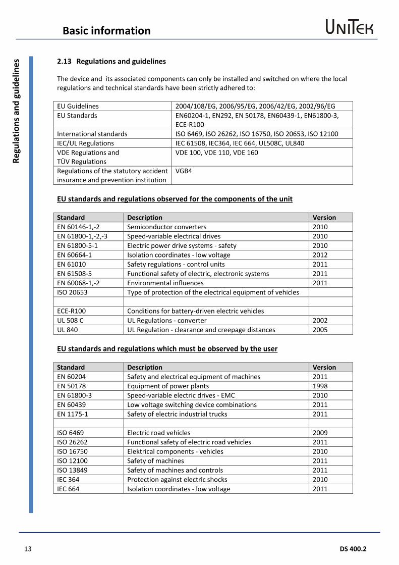
2.13 Regulations and guidelines
The device and its associated components can only be installed and switched on where the local regulations and technical standards have been strictly adhered to: EU Guidelines 2004/108/EG, 2006/95/EG, 2006/42/EG, 2002/96/EG EU Standards EN60204-1, EN292, EN 50178, EN60439-1, EN61800-3,
ECE-R100 International standards ISO 6469, ISO 26262, ISO 16750, ISO 20653, ISO 12100 IEC/UL Regulations IEC 61508, IEC364, IEC 664, UL508C, UL840 VDE Regulations and TÜV Regulations
VDE 100, VDE 110, VDE 160
Regulations of the statutory accident insurance and prevention institution
VGB4
EU standards and regulations observed for the components of the unit Standard Description Version EN 60146-1,-2 Semiconductor converters 2010 EN 61800-1,-2,-3 Speed-variable electrical drives 2010 EN 61800-5-1 Electric power drive systems - safety 2010 EN 60664-1 Isolation coordinates - low voltage 2012 EN 61010 Safety regulations - control units 2011 EN 61508-5 Functional safety of electric, electronic systems 2011 EN 60068-1,-2 Environmental influences 2011 ISO 20653 Type of protection of the electrical equipment of vehicles ECE-R100 Conditions for battery-driven electric vehicles UL 508 C UL Regulations - converter 2002 UL 840 UL Regulation - clearance and creepage distances 2005 EU standards and regulations which must be observed by the user Standard Description Version EN 60204 Safety and electrical equipment of machines 2011 EN 50178 Equipment of power plants 1998 EN 61800-3 Speed-variable electric drives - EMC 2010 EN 60439 Low voltage switching device combinations 2011 EN 1175-1 Safety of electric industrial trucks 2011 ISO 6469 Electric road vehicles 2009 ISO 26262 Functional safety of electric road vehicles 2011 ISO 16750 Elektrical components - vehicles 2010 ISO 12100 Safety of machines 2011 ISO 13849 Safety of machines and controls 2011 IEC 364 Protection against electric shocks 2010 IEC 664 Isolation coordinates - low voltage 2011
Basic information
DS 400.2 14
Risk
s 2.14 Risks
The manufacturer aims to keep the remaining risks emanating from the unit as low as possible by means of constructive, electrical, and software measures. In the field of drive engineering the following known remaining risks must be considered regarding the risks arising from machines, vehicles, and installations. Impermissible movements caused by:
• failure of safety watchdogs or switched-off safety watchdogs during commissioning or repair works
• software errors in upstream controls, errors in bus systems • non-monitored hardware and software errors in actuating elements and connecting
cables • inverted sense of control • faults during the parameter setting and wiring • limited response time of the control features. Ramps, limits • operations not permitted in the specifications • electromagnetic interferences • electrostatic interferences, lightning strikes • failure of components • failure in the brakes
Dangerous temperatures caused by:
• faults during the installation • faulty connections, bad contacts, aging • faults in the electric safety system, incorrect types of fuses • operations not permitted in the specifications • negative climatic conditions, lightning strikes • failure of components
Dangerous voltages caused by:
• faulty earthing of the unit or motor • faulty connections, bad contacts, aging • faulty potential isolation, failure of components • conductive contamination, condensation
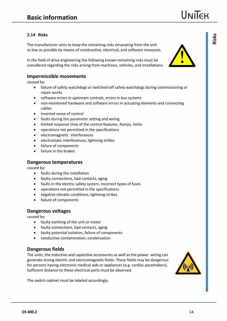
Dangerous fields The units, the inductive and capacitive accessories as well as the power wiring can generate strong electric and electromagnetic fields. These fields may be dangerous for persons having electronic medical aids or appliances (e.g. cardiac pacemakers). Sufficient distance to these electrical parts must be observed. The switch cabinet must be labeled accordingly.

15 DS 400.2
Basic information
Tech
nica
l dat
a 2.15 Technical data
Power supply connection DVC up to 1kW up to 18 kW
1/3 x 30V~ to 480V~ 3 x 30V~ to 480V~
+10% 50/60 Hz +10% 50/60 Hz
Auxiliary voltage connection EVL 24V= ±10% / 2A residual ripple <10% regenerating fuse
Data Unit DS-405.2 DS-412.2 DS-420.2 Supply voltage - rated value V~ 3x400 (480) Max. output voltage - rated value V~eff 3x390( (470)
Bus circuit voltage V= 560 (675)
Max. connection power S1 kVA 3.4 8.2 14
Max. power output S1 kW 3 7.5 13.5
Permanent current Aeff 5 12 20 Max. peak current Alo 10 24 40 Max. power loss W 80 150 250 Clock frequency kHz 8
Ballast switch-on voltage V= 750 ± 10
Over-voltage switching threshold V= 860 ± 10
Min. external ballast resistance Ω 8 51 40 Input fuse Switch-off integral
A A²s
10 150
20 200
40 300
Weight kg 3 3 3
Dimensions h x w x d mm 320x85x190
Installation pattern mm 100
Size 2 2 2 Control signals V A Funktion
Analog inputs ± 10 0.005 differential input
Digital inputs ON OFF
10-30 <6
0.010 ---
optically decoupled
Digital outputs +24 0.03 optically decoupled
Resolver differential input
Encoder input >3.6V optically decoupled
Encoder output >4.7 optically decoupled
CAN interface optically decoupled
RS232 interface 115200 (or 9600) Baud
Basic information
DS 400.2 16
Tech
nica
l dat
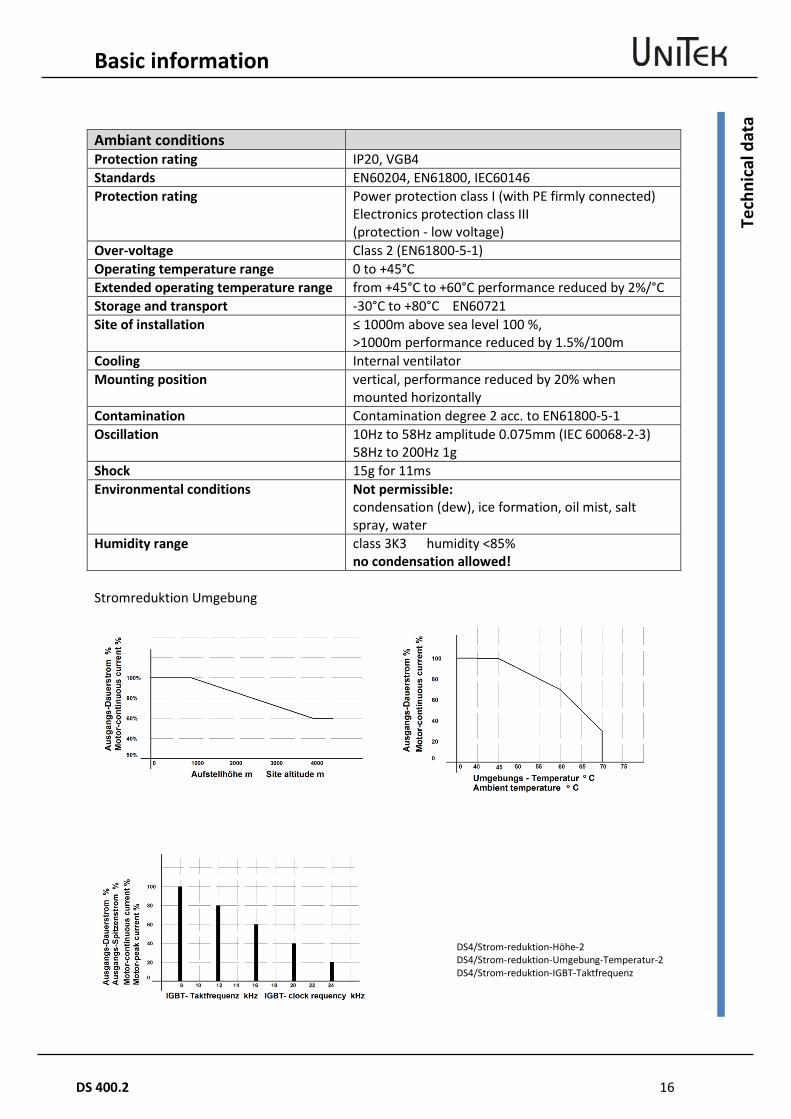
a Ambiant conditions Protection rating IP20, VGB4 Standards EN60204, EN61800, IEC60146 Protection rating Power protection class I (with PE firmly connected)
Electronics protection class III (protection - low voltage)
Over-voltage Class 2 (EN61800-5-1) Operating temperature range 0 to +45°C Extended operating temperature range from +45°C to +60°C performance reduced by 2%/°C Storage and transport -30°C to +80°C EN60721 Site of installation ≤ 1000m above sea level 100 %,
>1000m performance reduced by 1.5%/100m Cooling Internal ventilator Mounting position vertical, performance reduced by 20% when
mounted horizontally Contamination Contamination degree 2 acc. to EN61800-5-1 Oscillation 10Hz to 58Hz amplitude 0.075mm (IEC 60068-2-3)
58Hz to 200Hz 1g Shock 15g for 11ms Environmental conditions Not permissible:
condensation (dew), ice formation, oil mist, salt spray, water
Humidity range class 3K3 humidity <85% no condensation allowed!
Stromreduktion Umgebung
DS4/Strom-reduktion-Höhe-2 DS4/Strom-reduktion-Umgebung-Temperatur-2 DS4/Strom-reduktion-IGBT-Taktfrequenz

17 DS 400.2
Basic information
Tech
nica
l dat
a Blank page (for printing reasons)
Mechanical Installation
DS 400.2 18
Impo
rtan
t adv
ices
3 Mechanical Installation
3.1 Important advices
Pay attention to the ESD advices. Blank mounting surface, no lacquer (EMC surface-to-surface contact) The unit must be safely protected in the switch cabinet against mist and water and the intrusion of metallic dust. Check the device for mechanical damage. Only devices in perfect working order can be mounted. Disconnect the power supply prior to any assembly. For installations connected to an electric power supply install the shorting plug and affix the warning signs. The device must only mounted by suitably trained personnel. Vertical mounting position. Please note that there will be a performance reduction when the devices are mounted horizontally. Ensure that there is enough space for the discharged ventilation air (min. 100mm). Any bore hole dimensions for the fixation of the device must be taken from the dimension diagrams or from the drilling plan, not from the device. Drill the mounting bore holes into the mounting plate. Insert the device and fasten the screws. Note: Protect the device against intrusion of foreign particles (bore chips, screws, etc.)! The filter and the choke have to be mounted near to the device The line shields and the mounting plate must have surface-to-surface contact. Unshielded cable heads must be kept as short as possible. Braking resistors may become very hot (200°C). Install the resistors such that neither persons will be injured (burns) nor damage will occur due to the heat. Use vibration-proof screw connections. Inside temperature of the switch cabinet: max. 45°C For internal mounting ensure that the switch cabinet ventilation is sufficient. Use an air conditioning unit if the room temperatures are too high (>30°C).
Note: The operation of bedewed devices is not permissible.
19 DS 400.2
Mechanical Installation
Dim
ensi
ons D
S 40
5 –
DS
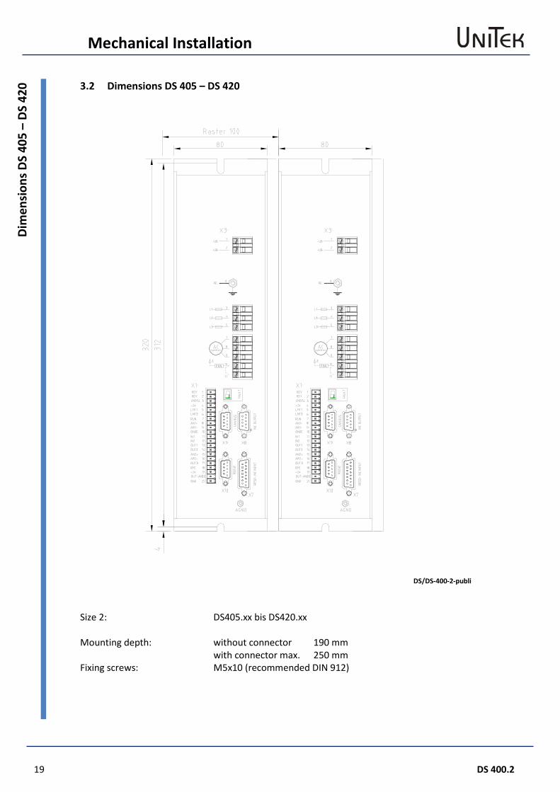
420 3.2 Dimensions DS 405 – DS 420
DS/DS-400-2-publi
Size 2: DS405.xx bis DS420.xx Mounting depth: without connector 190 mm with connector max. 250 mm Fixing screws: M5x10 (recommended DIN 912)
Mechanical Installation
DS 400.2 20
Dim
ensi
ons -
acc
esso
ries 3.3 Dimensions - accessories
EMV-Filter
DS/DS-400-Filter1 Grounding on case back
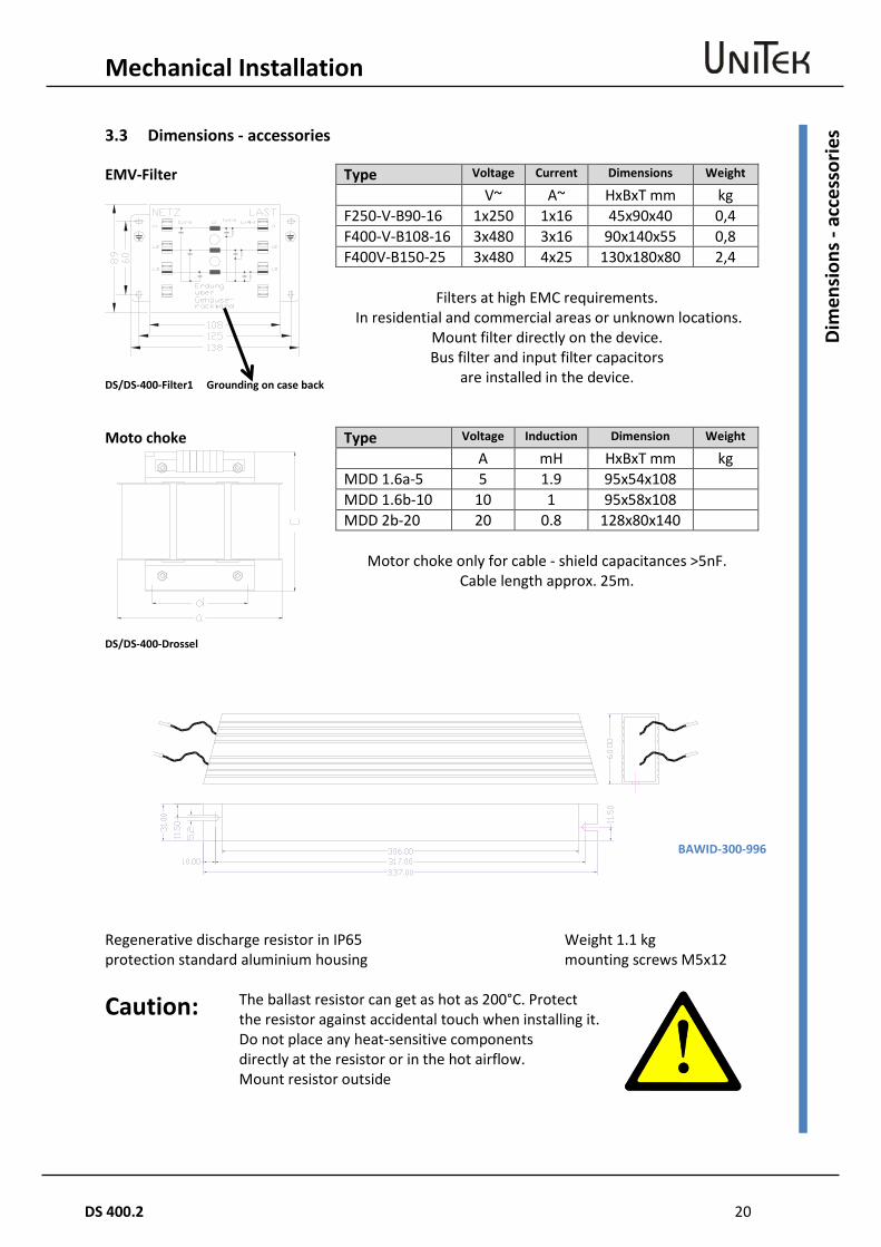
Type Voltage Current Dimensions Weight
V~ A~ HxBxT mm kg F250-V-B90-16 1x250 1x16 45x90x40 0,4 F400-V-B108-16 3x480 3x16 90x140x55 0,8 F400V-B150-25 3x480 4x25 130x180x80 2,4
Filters at high EMC requirements.
In residential and commercial areas or unknown locations. Mount filter directly on the device. Bus filter and input filter capacitors
are installed in the device.
Moto choke
DS/DS-400-Drossel
Type Voltage Induction Dimension Weight
A mH HxBxT mm kg MDD 1.6a-5 5 1.9 95x54x108 MDD 1.6b-10 10 1 95x58x108 MDD 2b-20 20 0.8 128x80x140
Motor choke only for cable - shield capacitances >5nF.
Cable length approx. 25m.
Regenerative discharge resistor in IP65 protection standard aluminium housing
Weight 1.1 kg mounting screws M5x12
Caution: The ballast resistor can get as hot as 200°C. Protect the resistor against accidental touch when installing it. Do not place any heat-sensitive components directly at the resistor or in the hot airflow. Mount resistor outside
BAWID-300-996
21 DS 400.2
Mechanical Installation
Inst
alla
tion 3.4 Installation
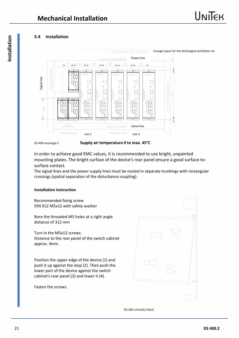
DS-400-montage-2 Supply air temperature 0 to max. 45°C In order to achieve good EMC values, it is recommended to use bright, unpainted mounting plates. The bright surface of the device's rear panel ensure a good surface-to-surface contact. The signal lines and the power supply lines must be routed in separate trunkings with rectangular crossings (spatial separation of the disturbance coupling).
Installation instruction
DS-400-schrank2-block
Recommended fixing screw DIN 912 M5x12 with safety washer Bore the threaded M5 holes at a right angle distance of 312 mm Turn in the M5x12 screws. Distance to the rear panel of the switch cabinet approx. 4mm. Position the upper edge of the device (1) and push it up against the stop (2). Then push the lower part of the device against the switch cabinet's rear panel (3) and lower it (4). Fasten the screws.
Enough space for the discharged ventilation air
Power line
size 1 size 2
signal line
Sign
al li
ne
Electrical installation
DS 400.2 22
Impo
rtan
t adv
ice 4 Electrical installation
4.1 Important advice
The order of the connections to the connector or terminal numbers is obligatory. All further advice is non-obligatory. The input and output conductors may be altered or supplemented in accordance with the electrical standards and guidelines. Adhere to: - connection and operating instructions - local regulations - EU EG regulations such as the 2006/42/EG machine directive - VDE and TÜV regulations and Trade body guidelines
Electrical installation should only be carried out when all voltages have been removed! Ensure that the device is safely disconnected from the power supply - place the short-circuit bracket - affix warning signs The installation should only be carried out by suitably trained personnel for electrical engineering. Compare the connection data with those indicated on the type plate. Ensure that the correct fuses have been provided for the power supply, the auxiliary voltage, and the external ballast resistors. Use a pre-charging circuit (UNITEK Inrush limiter). Power supply conductors and control lines must be routed separately from each other. Connection shields and grounding must be carried out in compliance with the EMC guidelines. Use the correct line cross-sections. Note: Always connect the BTB contact into the safety circuit! Note: The PE connection must comply with the standard EN61800-5-1.
Operation without a PE-connection is not allowed!
23 DS 400.2
Electrical installation
Circ
uit d
iagr
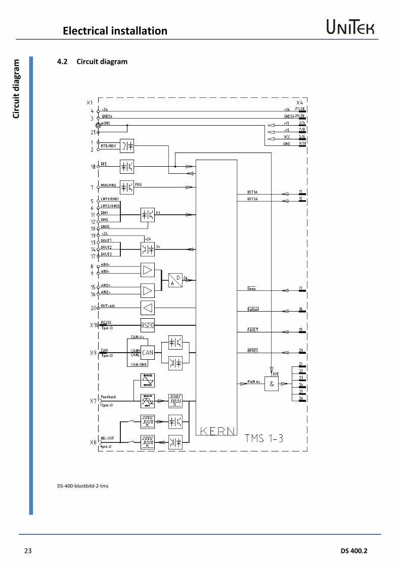
am 4.2 Circuit diagram
DS-400-blockbild-2-tms
Electrical installation
DS 400.2 24
Circ
uit d
iagr
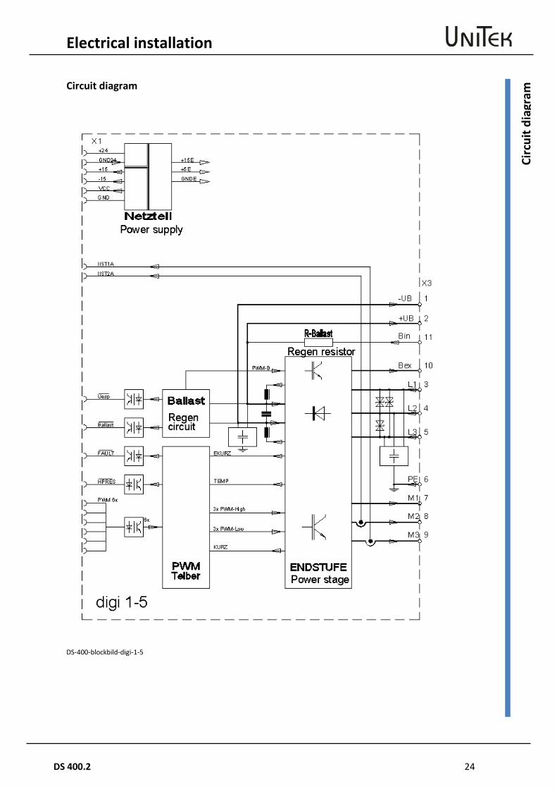
am Circuit diagram
DS-400-blockbild-digi-1-5
25 DS 400.2
Electrical installation
Conn
ectio
n di
agra
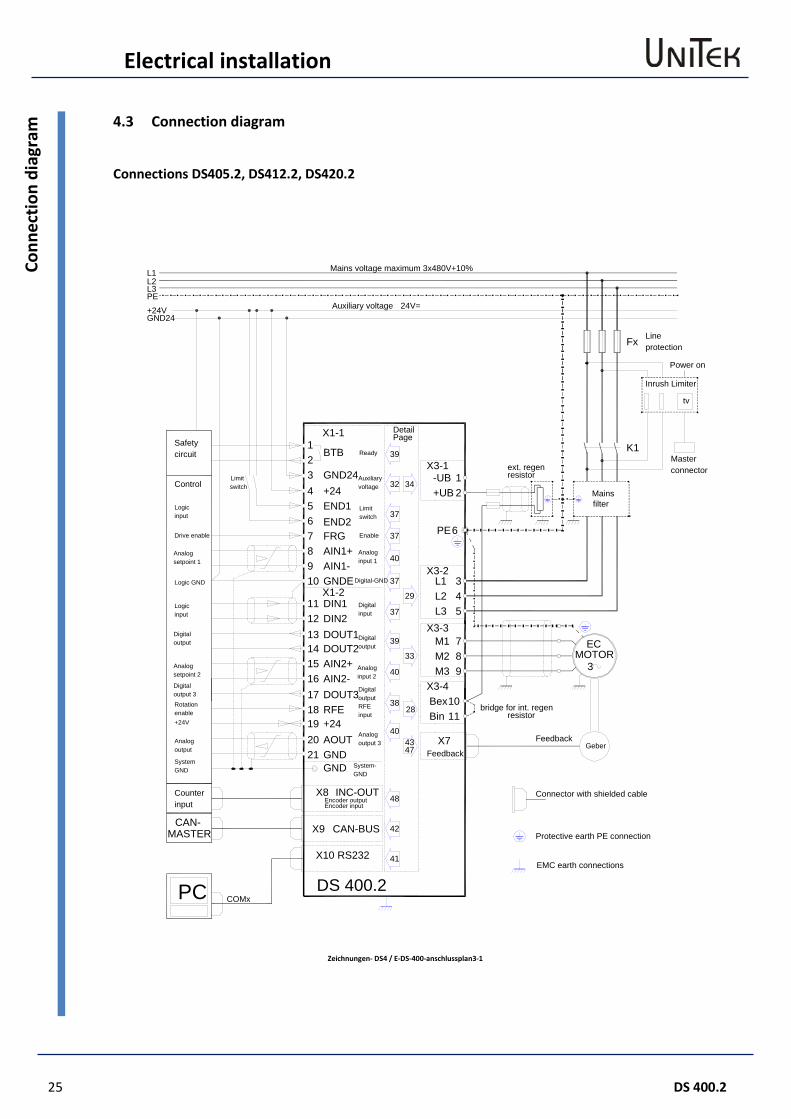
m 4.3 Connection diagram
Connections DS405.2, DS412.2, DS420.2
Zeichnungen- DS4 / E-DS-400-anschlussplan3-1
12
6
345
789
1011
K1
Fx
-UB+UB
PE
L1L2L3
M1M2M3
BinBex
ECMOTOR
3
Geber
X3-1
X3-2
X3-3
X3-4
X7
X10
X9
X8
X1-1
X1-2
12345678910
1112131415161718
BTB
GND24+24END1END2FRG
GNDE
AIN2+AIN2-DOUT3RFE
DIN1DIN2DOUT1DOUT2
AIN1+AIN1-
INC-OUT
CAN-BUS
RS232
CAN-MASTER
GND System-GND
L1L2L3PE
+24VGND24
PC COMxDS 400.2
39
32 34
37
37
40
37
29
37
39
33
40
38
40
48
42
28
4347
41
192021
+24AOUTGND
Masterconnector
Lineprotection
Mainsfilter
ext. regenresistor
Auxiliary voltage
Mains voltage maximum 3x480V+10%
24V=
Safetycircuit
Control
Protective earth PE connection
EMC earth connections
Connector with shielded cable
Drive enable
Analogsetpoint 1
Logic GND
Logicinput
Digitaloutput
Analogoutput
SystemGND
Enable
Analoginput 1
Digital-GND
Digitalinput
Digitaloutput
Analoginput 2
Analogoutput 3
Limitswitch
Auxiliaryvoltage
Ready
DetailPage
Limitswitch
Encoder outputCounterinput
Rotationenable+24V
Digitaloutput 3
Analogsetpoint 2
DigitaloutputRFEinput
Encoder input
Feedback
Feedback
Logicinput
bridge for int. regenresistor
Inrush Limiter
Power on
tv
Electrical installation
DS 400.2 26
Conn
ectio
ns D
S405
.2, D
S412
.2, D
S420
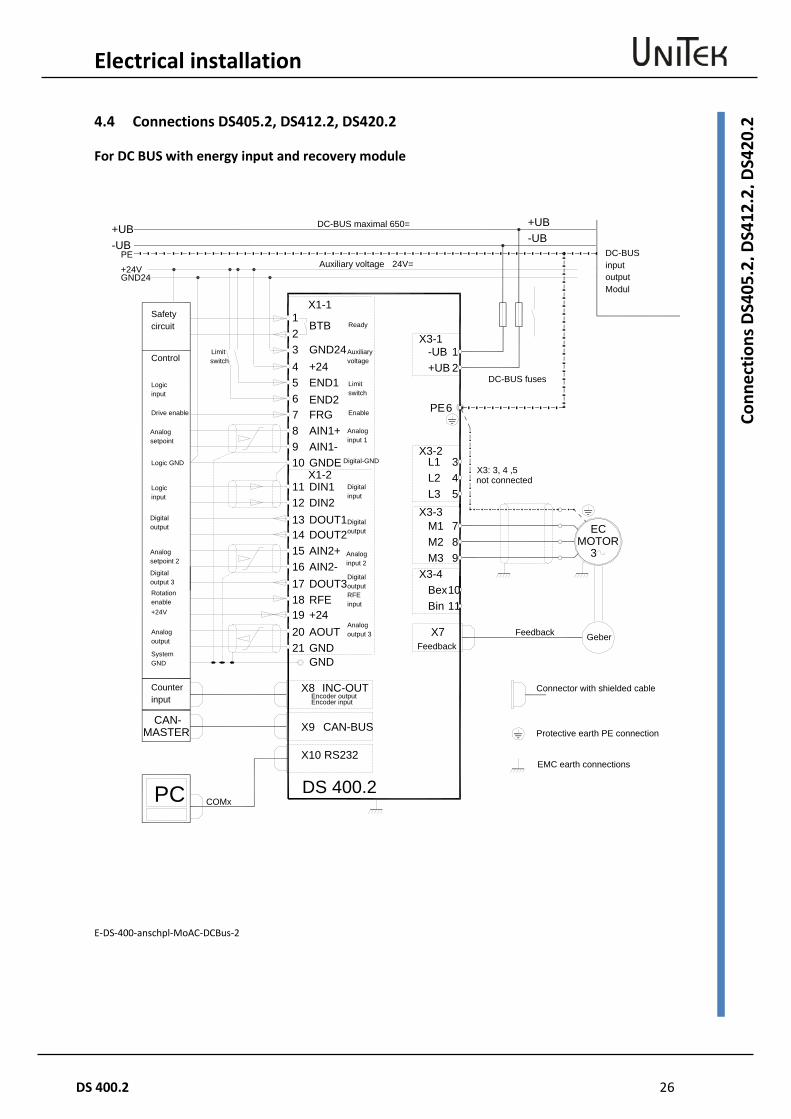
.2 4.4 Connections DS405.2, DS412.2, DS420.2
For DC BUS with energy input and recovery module
E-DS-400-anschpl-MoAC-DCBus-2
12
6
345
789
1011
-UB+UB
PE
L1L2L3
M1M2M3
BinBex
ECMOTOR
3
X3-1
X3-2
X3-3
X3-4
X7
PE
+24VGND24
-UB+UB
X3: 3, 4 ,5
+UB-UB
Geber
X10
X9
X8
X1-1
X1-2
12345678910
1112131415161718
BTB
GND24+24END1END2FRG
GNDE
AIN2+AIN2-DOUT3RFE
DIN1DIN2DOUT1DOUT2
AIN1+AIN1-
INC-OUT
CAN-BUS
RS232
CAN-MASTER
GND
PC COMxDS 400.2
192021
+24AOUTGND
DC-BUSinput
DC-BUS fuses
Auxiliary voltage
DC-BUS maximal 650=
24V=
Safetycircuit
Control
Protective earth PE connection
EMC earth connections
Connector with shielded cable
Drive enable
Analogsetpoint
Logic GND
Logicinput
Digitaloutput
Analogoutput
SystemGND
Enable
Analoginput 1
Digital-GND
Digitalinput
Digitaloutput
Analoginput 2
Analogoutput 3
Limitswitch
Auxiliaryvoltage
Ready
Limitswitch
Encoder outputCounterinput
Rotationenable+24V
Digitaloutput 3
Analogsetpoint 2
DigitaloutputRFEinput
outputModul
not connected
FeedbackFeedback
Encoder input
Logicinput
27 DS 400.2
Electrical installation
Conn
ecto
rs
DS4
05.2
/DS4
12.2
/DS4
20.2
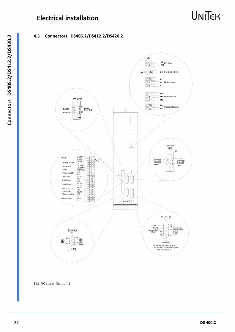
4.5 Connectors DS405.2/DS412.2/DS420.2
E-DS-400-steckerübersicht-1
DC Bus
Main Power
Motor Power
Regen Resistor1110
7
98
5
34
6
21
Bin
Bex
M3
M1
M2
L3
L2
L1
PE
+UB
-UB
X3
Bex
Bin
M3
L3
M2
M1
L2
L1
PE
+UB
-UB
Earth Contact
Cannel NCannel BCannel A
GND
+5V
Encoderoutput
67
98 33
M
1122
445
X8
CAN-V+
CAN-H1
34
FM
5
2
nc98
nc 67 CAN-GND
ncnc
CAN-Lnc
CAN-BUSX9
12DIN2
AIN2-DOUT3RFE
DOUT1
AIN2+DOUT2
16
1817
1415
13
4+24END1/LMT1END2/LMT2
AIN1+AIN1-
DIN1GNDE
FRG/RUN8
1011
9
67
5
GND24BTB/RDYBTB/RDY
23
1
X1
Resolver
MotorTemperatur
ncnc
nc109
11
REF1COS1SIN2
1312
1415
REF24
M
nc123 COS2
SIN1
Motor (GND)Temperatur
ncnc
nc
7
56
8
X7
CTSRTS
5 GND
FM
X10
12
43
nc
nc
89
76
RS232
TXDTR
RXnc
RTSCTS
GND
7
nc 98 3
45
DTRTX
nc 6 nc21
RX
RS232X10
FM
nc
ncCAN-V+
CAN-H 389 5
4 ncnc
76
21 nc
CAN-GNDCAN-L
CAN-BUSX9
FM
+24AOUTGND
input
AGND
Cannel ACannel BCannel NSelect
Ready
Auxiliary voltage
Limit Switch
Enable
Analog Input 1
Logic GND
Digital Input
Digital Output
Analog Input 2
Analog output
Digital OutputRotation enable
further feedback connections
see page 37 to 40Incrementel TTL, SINCOS, Rotor
Electrical installation
DS 400.2 28
EMC 4.6 EMC
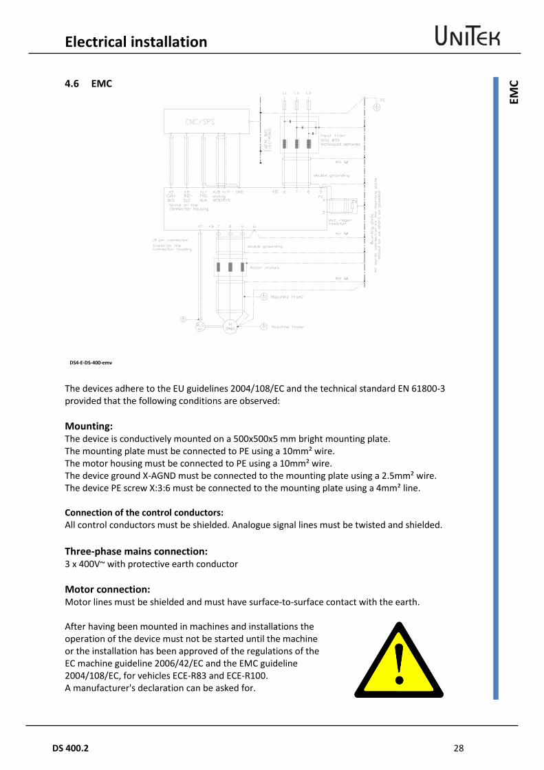
The devices adhere to the EU guidelines 2004/108/EC and the technical standard EN 61800-3 provided that the following conditions are observed: Mounting: The device is conductively mounted on a 500x500x5 mm bright mounting plate. The mounting plate must be connected to PE using a 10mm² wire. The motor housing must be connected to PE using a 10mm² wire. The device ground X-AGND must be connected to the mounting plate using a 2.5mm² wire. The device PE screw X:3:6 must be connected to the mounting plate using a 4mm² line. Connection of the control conductors: All control conductors must be shielded. Analogue signal lines must be twisted and shielded. Three-phase mains connection: 3 x 400V~ with protective earth conductor Motor connection: Motor lines must be shielded and must have surface-to-surface contact with the earth. After having been mounted in machines and installations the operation of the device must not be started until the machine or the installation has been approved of the regulations of the EC machine guideline 2006/42/EC and the EMC guideline 2004/108/EC, for vehicles ECE-R83 and ECE-R100. A manufacturer's declaration can be asked for.
DS4-E-DS-400-emv
29 DS 400.2
Electrical installation
Mai
ns c
onne
ctio
n 4.7 Mains connection
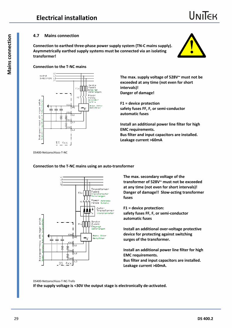
Connection to earthed three-phase power supply system (TN-C mains supply). Asymmetrically earthed supply systems must be connected via an isolating transformer! Connection to the T-NC mains
DS400-Netzanschluss-T-NC
The max. supply voltage of 528V~ must not be exceeded at any time (not even for short intervals)! Danger of damage! F1 = device protection safety fuses FF, F, or semi-conductor automatic fuses Install an additional power line filter for high EMC requirements. Bus filter and input capacitors are installed. Leakage current >60mA
Connection to the T-NC mains using an auto-transformer
DS400-Netzanschluss-T-NC-Trafo
The max. secondary voltage of the transformer of 528V~ must not be exceeded at any time (not even for short intervals)! Danger of damage!! Slow-acting transformer fuses F1 = device protection: safety fuses FF, F, or semi-conductor automatic fuses Install an additional over-voltage protective device for protecting against switching surges of the transformer. Install an additional power line filter for high EMC requirements. Bus filter and input capacitors are installed. Leakage current >60mA.
If the supply voltage is <30V the output stage is electronically de-activated.
Electrical installation
DS 400.2 30
Mai
ns c
onne
ctio
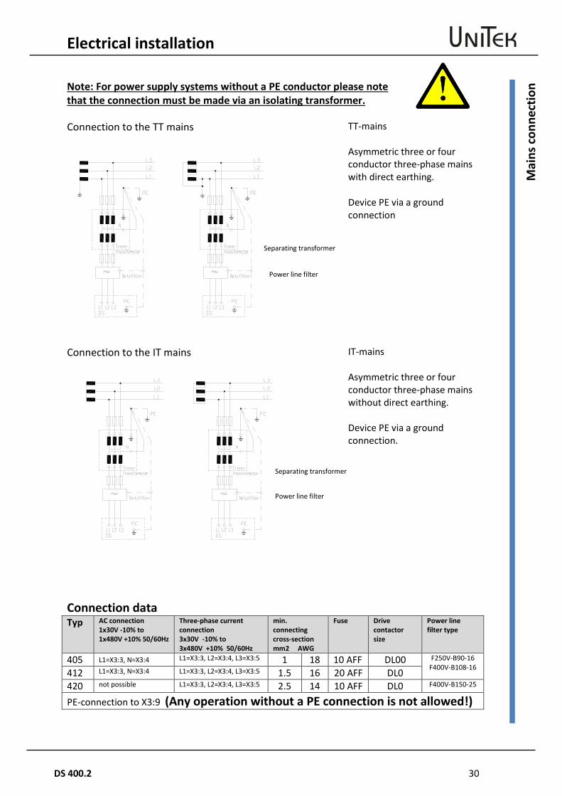
n Note: For power supply systems without a PE conductor please note that the connection must be made via an isolating transformer. Connection to the TT mains
TT-mains
Asymmetric three or four conductor three-phase mains with direct earthing. Device PE via a ground connection
Connection to the IT mains
IT-mains Asymmetric three or four conductor three-phase mains without direct earthing. Device PE via a ground connection.
Connection data Typ AC connection
1x30V -10% to 1x480V +10% 50/60Hz
Three-phase current connection 3x30V -10% to 3x480V +10% 50/60Hz
min. connecting cross-section mm2 AWG
Fuse Drive contactor size
Power line filter type
405 L1=X3:3, N=X3:4 L1=X3:3, L2=X3:4, L3=X3:5 1 18 10 AFF DL00 F250V-B90-16 F400V-B108-16 412 L1=X3:3, N=X3:4 L1=X3:3, L2=X3:4, L3=X3:5 1.5 16 20 AFF DL0
420 not possible L1=X3:3, L2=X3:4, L3=X3:5 2.5 14 10 AFF DL0 F400V-B150-25
PE-connection to X3:9 (Any operation without a PE connection is not allowed!)
Separating transformer
Power line filter
Separating transformer
Power line filter

31 DS 400.2
Electrical installation
Pre-
char
ging
4.8 Pre-charging
Inrush current With the first switching-on the inrush current is internally limited to a 10-fold rated current value (approx. 2ms) by means of a NTC resistor. The effect persists when between switching off and switching on again a waiting time interval of 180s is adhered to. The NTC resistor is placed in the cooling air flow of the device ventilator. Note: Always check the switching capacity K1 Fast switching off/on If the switch off-on sequence is fast the inrush current may rise to a 30-fold higher value (1ms)
DS4/DS-400-Vorladung-2 Attention: The drive contactor K1 and the input rectifier may be damaged. A pre-charging unit must be installed. Pre-charging with inrush limiter The charging current is limited to <10A by means of the UNITEK Inrush Limiter. The power contactor K1 is switched on after a delay time. Attention: The drive contactor must not be switched under load. Switching on-off only when the enable is blocked. No voltage applying across FRG/RUN (X1:7).
Electrical installation
DS 400.2 32
Auxi
liary
vol
tage
con
nect
ion
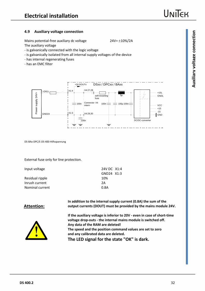
4.9 Auxiliary voltage connection
Mains potential-free auxiliary dc voltage 24V= ±10%/2A The auxiliary voltage - is galvanically connected with the logic voltage - is galvanically isolated from all internal supply voltages of the device - has internal regenerating fuses - has an EMC filter
DS-BAx-DPC/E-DS-400-Hilfsspannung External fuse only for line protection.
Input voltage 24V DC X1:4 GND24 X1:3 Residual ripple 10% Inrush current 2A Nominal current 0.8A
Attention: In addition to the internal supply current (0.8A) the sum of the output currents (DOUT) must be provided by the mains module 24V.
If the auxiliary voltage is inferior to 20V - even in case of short-time voltage drop-outs - the internal mains module is switched off. Any data of the RAM are deleted! The speed and the position command values are set to zero and any calibrated data are deleted. The LED signal for the state "OK" is dark.
+15LGNDL
VCC+15-15GND
100n100u100n
100n
100n
+24 DOUTx
X1:4
X1:3
X4:27,28
X4:29,30
intern
5u
+24V=
GND24
DSxx / DPCxx / BAxx
Pow
er s
uppl
y 24
V=
self-ressetingfuse
DC/DC-converter
Connector X4
33 DS 400.2
Electrical installation
Mot
or c
onne
ctio
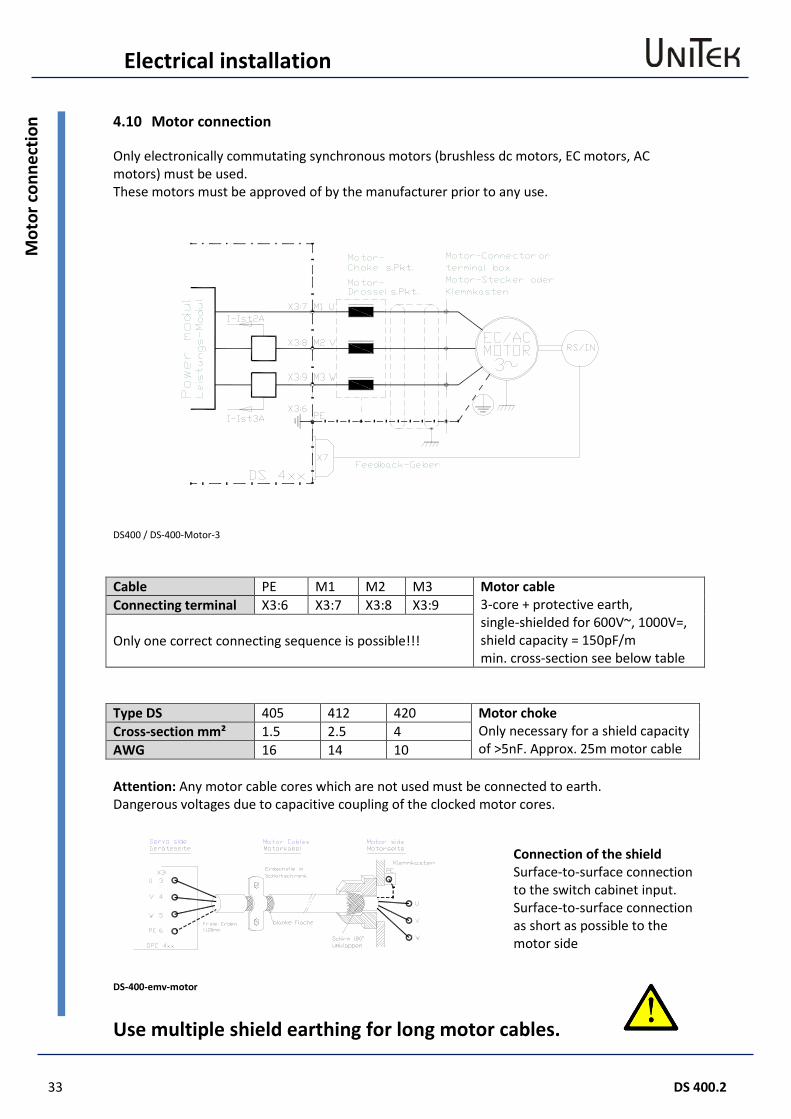
n 4.10 Motor connection
Only electronically commutating synchronous motors (brushless dc motors, EC motors, AC motors) must be used. These motors must be approved of by the manufacturer prior to any use.
DS400 / DS-400-Motor-3 Cable PE M1 M2 M3 Motor cable
3-core + protective earth, single-shielded for 600V~, 1000V=, shield capacity = 150pF/m min. cross-section see below table
Connecting terminal X3:6 X3:7 X3:8 X3:9
Only one correct connecting sequence is possible!!!
Type DS 405 412 420 Motor choke
Only necessary for a shield capacity of >5nF. Approx. 25m motor cable
Cross-section mm² 1.5 2.5 4 AWG 16 14 10 Attention: Any motor cable cores which are not used must be connected to earth. Dangerous voltages due to capacitive coupling of the clocked motor cores.
DS-400-emv-motor
Use multiple shield earthing for long motor cables.
Connection of the shield Surface-to-surface connection to the switch cabinet input. Surface-to-surface connection as short as possible to the motor side

Electrical installation
DS 400.2 34
Balla
st c
ircui
t D
S405
/ D
S412
/ D
S420
4.11 Ballast circuit DS405 / DS412 / DS420
DS-BAx-DPC / E-DS-400-ballast-3 The energy arising during the braking operation is fed back into the dc bus circuit. The bus circuit Elkos can store only little energy. Any surplus of energy is transformed into heat in the ballast resistor. The internal ballast resistance is rated for drives without centrifugal mass. Always use external resistors for centrifugal masses or in case of uncertainties concerning the rating. Type DS 405 412 420 Installed resistor Ohm 80 51 42 Continuous power W 50 100 Pulse power 1s kW 1 2.5 External resistor min. Ohm 80 51 40 Fuse F2 AF 10 16 25 Note: For DS420: Observe the motor centrifugal mass (rotor moment of inertia). The power of the internal ballast resistance is only 100 W. Install an external ballast resistor. Caution: Ballast resistors may become very hot. !
-UB
+UB
BAL
X3:1
X3:2
X3:10
X3:11
F2-1
F2-2
DSxx/BAxx
Pow
er-M
odul ext. regen
resistor
bridgewith internal regen resistor
regenfuses
35 DS 400.2
Electrical installation
Balla
st –
dim
ensi
onin
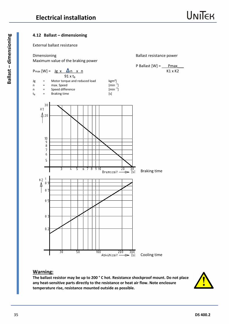
g 4.12 Ballast – dimensioning
External ballast resistance Dimensioning Maximum value of the braking power Pmax [W] = Jg x n x n 91 x tB
Ballast resistance power P Ballast [W] = ___Pmax___ K1 x K2
Jg n n tB
= = = =
Motor torque and reduced load max. Speed Speed difference Braking time
kgm²] [min -1] [min -1] [s]
Warning: The ballast resistor may be up to 200 ° C hot. Resistance shockproof mount. Do not place any heat-sensitive parts directly to the resistance or heat air flow. Note enclosure temperature rise, resistance mounted outside as possible.
Braking time
Cooling time
Electrical installation
DS 400.2 36
Balla
st –
dim
ensi
onin
g Blank page (for printing reasons)
37 DS 400.2
Control connection
Dig
ital i
nput
5 Control connection
5.1 Digital input
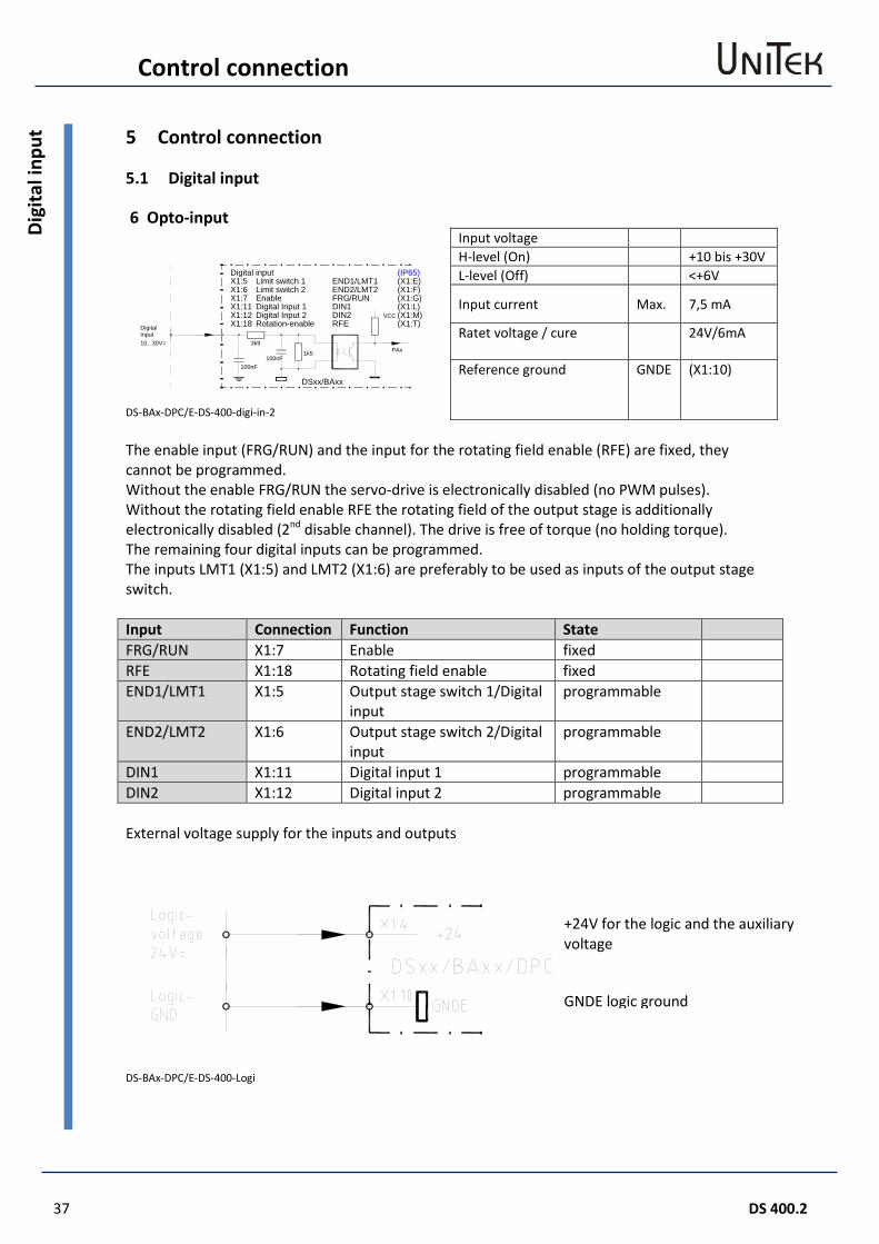
6 Opto-input
DS-BAx-DPC/E-DS-400-digi-in-2
Input voltage H-level (On) +10 bis +30V L-level (Off) <+6V
Input current Max. 7,5 mA
Ratet voltage / cure
24V/6mA
Reference ground GNDE (X1:10)
The enable input (FRG/RUN) and the input for the rotating field enable (RFE) are fixed, they cannot be programmed. Without the enable FRG/RUN the servo-drive is electronically disabled (no PWM pulses). Without the rotating field enable RFE the rotating field of the output stage is additionally electronically disabled (2nd disable channel). The drive is free of torque (no holding torque). The remaining four digital inputs can be programmed. The inputs LMT1 (X1:5) and LMT2 (X1:6) are preferably to be used as inputs of the output stage switch. Input Connection Function State FRG/RUN X1:7 Enable fixed RFE X1:18 Rotating field enable fixed END1/LMT1 X1:5 Output stage switch 1/Digital
input programmable
END2/LMT2 X1:6 Output stage switch 2/Digital input
programmable
DIN1 X1:11 Digital input 1 programmable DIN2 X1:12 Digital input 2 programmable External voltage supply for the inputs and outputs
DS-BAx-DPC/E-DS-400-Logi
X1:5 END1/LMT1X1:6 END2/LMT2X1:7 FRG/RUNX1:11 DIN1X1:12 DIN2 VCC
PAx3k9
1k5100nF
100nF
Digital
10...30V=Input
DSxx/BAxx
X1:18 RFE
Digital inputLimit switch 1Limit switch 2EnableDigital Input 1Digital Input 2Rotation-enable
(X1:E)(X1:F)(X1:G)(X1:L)(X1:M)(X1:T)
(IP65)
+24V for the logic and the auxiliary voltage
GNDE logic ground
Control connection
DS 400.2 38
Safe
ty in
put R
FE (r
otat
ing
field
ena
ble)
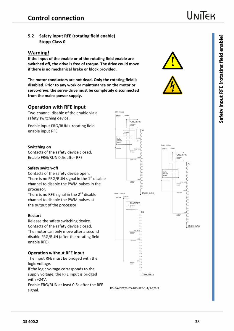
5.2 Safety input RFE (rotating field enable) Stopp-Class 0
Warning! If the input of the enable or of the rotating field enable are switched off, the drive is free of torque. The drive could move if there is no mechanical brake or block provided. The motor conductors are not dead. Only the rotating field is disabled. Prior to any work or maintenance on the motor or servo-drive, the servo-drive must be completely disconnected from the mains power supply.
Operation with RFE input
DS-BAxDPC/E-DS-400-REF-1-1/1-2/1-3
Two-channel disable of the enable via a safety switching device.
Enable input FRG/RUN + rotating field enable input RFE Switching on Contacts of the safety device closed. Enable FRG/RUN 0.5s after RFE Safety switch-off Contacts of the safety device open: There is no FRG/RUN signal in the 1st disable channel to disable the PWM pulses in the processor, There is no RFE signal in the 2nd disable channel to disable the PWM pulses at the output of the processor. Restart Release the safety switching device. Contacts of the safety device closed. The motor can only move after a second disable FRG/RUN (after the rotating field enable RFE). Operation without RFE input The input RFE must be bridged with the logic voltage. If the logic voltage corresponds to the supply voltage, the RFE input is bridged with +24V. Enable FRG/RUN at least 0.5s after the RFE signal.
21
20
19
18
17
16
15
14
13
12
11
10
9
8
7
6
5
4
3
2
1
CNC/SPSHardware
PNOZ
HardwareFRG / RUN
RFE
+24V=GND24
X1
DSxx, BAxx
GNDE
GND24
+24V=
+24
GND24
Enable
SafityDevice
Enable
Rotationenable
Logic-GND
24V- Voltage
21
20
19
18
17
16
15
14
13
12
11
10
9
8
7
6
5
4
3
2
1
CNC/SPSHardware
PNOZ
HardwareFRG / RUN
RFE
+24V=GND24
X1
DSxx, BAxx
GNDE
Enable
SafityDevice
Enable
Rotationenable
Logic-GND
Logik - Voltage
21
20
19
18
17
16
15
14
13
12
11
10
9
8
7
6
5
4
3
2
1
CNC/SPSHardware
HardwareFRG / RUN
RFE
+24V=GND24
X1
DSxx, BAxx
GNDE
Enable
Enable
Rotationenable
Logic-GND
Logic - Voltage
39 DS 400.2
Control connection
Dig
ital o
utpu
ts (o
pen
emitt
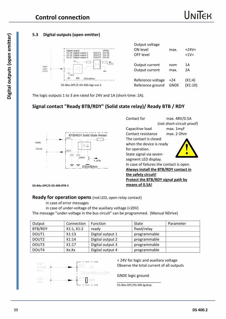
er) 5.3 Digital outputs (open emitter)
DS-BAx-DPC/E-DS-400-digi-out-2
Output voltage ON level max. +24V= OFF level <1V= Output current nom 1A Output current max. 2A Reference voltage +24 (X1:4) Reference ground GNDE (X1:10)
The logic outputs 1 to 3 are rated for 24V and 1A (short-time: 2A). Signal contact "Ready BTB/RDY" (Solid state relay)/ Ready BTB / RDY
DS-BAx-DPC/E-DS-400-BTB-3
Contact for max. 48V/0.5A (not short-circuit proof)
Capacitive load max. 1myF Contact resistance max. 2 Ohm The contact is closed when the device is ready for operation. State signal via seven-segment LED display. In case of failures the contact is open. Always install the BTB/RDY contact in the safety circuit! Protect the BTB/RDY signal path by means of 0.5A!
Ready for operation opens (red LED, open relay contact) in case of error messages in case of under-voltage of the auxiliary voltage (<20V) The message "under-voltage in the bus circuit" can be programmed. (Manual NDrive) Output Connection Function State Parameter BTB/RDY X1:1, X1:2 ready fixed/relay DOUT1 X1:13 Digital output 1 programmable DOUT2 X1:14 Digital output 2 programmable DOUT3 X1:17 Digital output 3 programmable DOUT4 Xx:Xx Digital output 4 programmable
+ 24V for logic and auxiliary voltage Observe the total current of all outputs GNDE logic ground _____________________ DS-BAx-DPC/DS-400-lgoiksp
X1:13 DOUT1X1:14 DOUT2
+24
F_AUSx
100nF
24V/1A
DSxx/BAxx
X1:17 DOUT3
Digital outputDigital output 1Digital output 2Digital output 3
Digitaloutput
(X1:N)(X1:O)(X1:S)
(IP65)
BTB/RDY Solid State Relais
F_BTB100nF
X1:1
X1:2
DSxx/BAxx
Safity
Circuit
Control connection
DS 400.2 40
Dig
ital o
utpu
ts (o
pen
emitt
er)
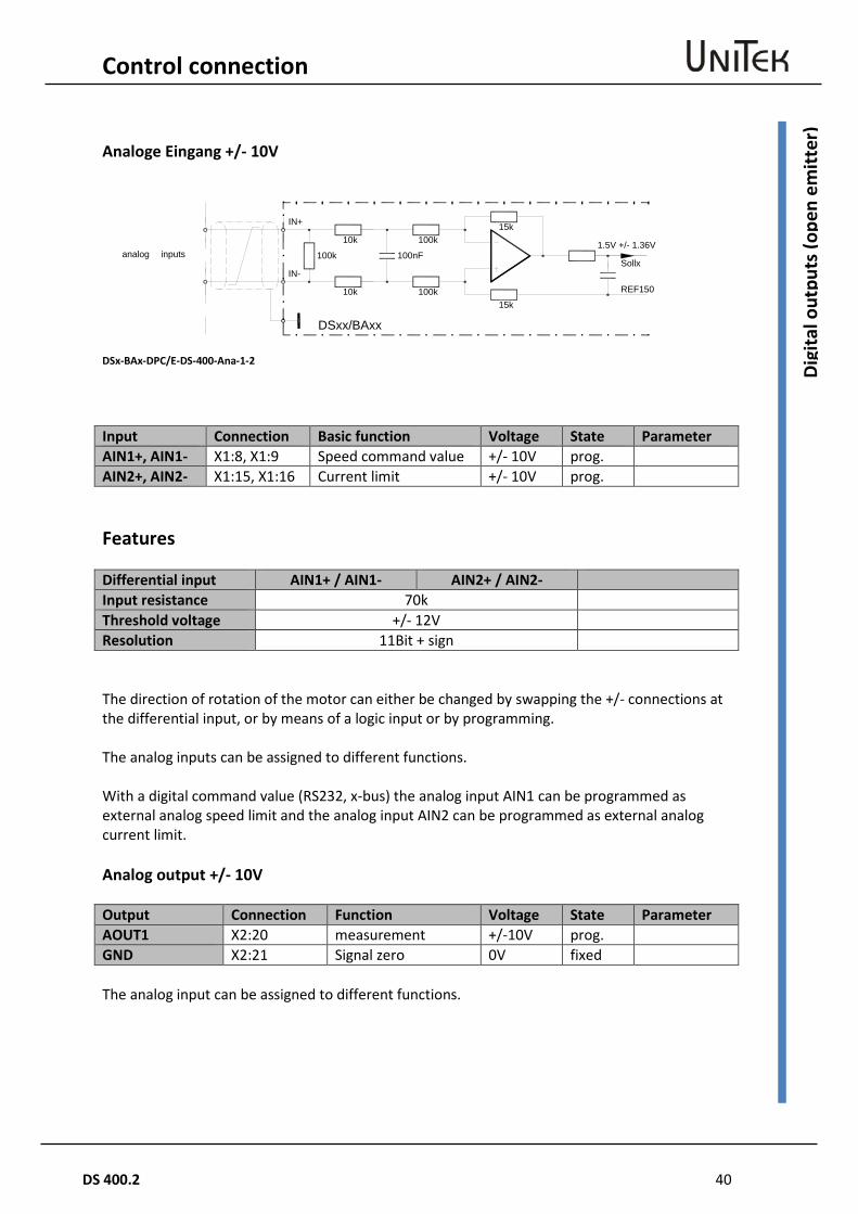
Analoge Eingang +/- 10V
DSx-BAx-DPC/E-DS-400-Ana-1-2 Input Connection Basic function Voltage State Parameter AIN1+, AIN1- X1:8, X1:9 Speed command value +/- 10V prog. AIN2+, AIN2- X1:15, X1:16 Current limit +/- 10V prog. Features Differential input AIN1+ / AIN1- AIN2+ / AIN2- Input resistance 70k Threshold voltage +/- 12V Resolution 11Bit + sign The direction of rotation of the motor can either be changed by swapping the +/- connections at the differential input, or by means of a logic input or by programming. The analog inputs can be assigned to different functions. With a digital command value (RS232, x-bus) the analog input AIN1 can be programmed as external analog speed limit and the analog input AIN2 can be programmed as external analog current limit. Analog output +/- 10V Output Connection Function Voltage State Parameter AOUT1 X2:20 measurement +/-10V prog. GND X2:21 Signal zero 0V fixed The analog input can be assigned to different functions.
Sollx
REF150
10k 100k
100k 100nF
15k
10k 100k15k
IN+
IN-
DSxx/BAxx
1.5V +/- 1.36Vanalog inputs
41 DS 400.2
Control connection
Seria
l int
erfa
ce R
S 23
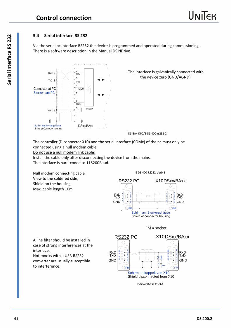
2 5.4 Serial interface RS 232
Via the serial pc interface RS232 the device is programmed and operated during commissioning. There is a software description in the Manual DS NDrive.
The interface is galvanically connected with
the device zero (GND/AGND).
________________________ DS-BAx-DPC/E-DS-400-rs232-2
The controller (D connector X10) and the serial interface (COMx) of the pc must only be connected using a null modem cable. Do not use a null modem link cable! Install the cable only after disconnecting the device from the mains. The interface is hard-coded to 115200Baud. Null modem connecting cable View to the soldered side, Shield on the housing, Max. cable length 10m
E-DS-400-RS232-Verb-1
FM = socket
A line filter should be installed in case of strong interferences at the interface. Notebooks with a USB-RS232 converter are usually susceptible to interference.
E-DS-400-RS232-FI-1
Schirm am Steckergehäuse
62
5
FM
437
89
1 6
FM
789
2
543
1RxDTxD
GND GNDTxDRxD
RS232 PC DSxx/BAxxX10
Shield at connector housing
62
5
FM
437
89
1 6
FM
789
2
543
1RxDTxD
GND GNDTxDRxD
RS232 PC
Schirm entkoppelt von X10
DSxx/BAxxX10
2k2
2k2
1k 100n
Shield disconnected from X10
Schirm am Steckergehäuse
2
3
4T2OU
7
8R2IN
5 RS232
RxD
TxD
2
3
5GND
Stecker am PC
RxD
TxD
DSxx/BAxx
Connector at PC
Shield at Connector housing

Control connection
DS 400.2 42
CAN
-BU
S 5.5 CAN-BUS
The CAN-BUS is a digital connection to the CNC control. Optimum conditions are achieved with CNC controls and CAN components of LABOD electronic or CAN Open. Programming and operation by means of the control panel via the CAN-BUS. Interface complies with the standard ISO 11898. Adjustment and programming see Manual DS-CAN.
CAN BUS cable Use a shielded bus conductor with a low shielding capacity. Signal plus GND. D-connector with a metal or metallized housing. LiYCY 4x0.25+shield.
Designation Connector
no. Cable colour Cable no.
CAN-V+ 9 brown 1 CAN-GND 3 white 4 (PE) CAN-H 7 green 3 CAN-L 2 yellow 2 FM=jack CAN BUS connection with several devices
Master Address xx Address xx Address xx
DS-BAx-DPC / E-DS-400-CAN-3x3
Terminating resistor at the end of the bus line > 120 Ohm between CAN-H and CAN-L
1
34
FM
5
2
98
67
1
34
FM
5
2
98
67
CAN-V+
CAN-H1
34
FM
5
2
98
67
CAN-GND
CAN-L
(PE)Schirm am Steckergehäuse
X9 X9 X9
CA
N-B
US
DSxx/BAxx DSxx/BAxx DSxx/BAxx
120
Shield at connector housing
The BUS interface is galvanically isolated from the internal device voltage. The voltage is supplied via an internal isolated DC-DC converter.
43 DS 400.2
Control connection
Reso
lver
con
nect
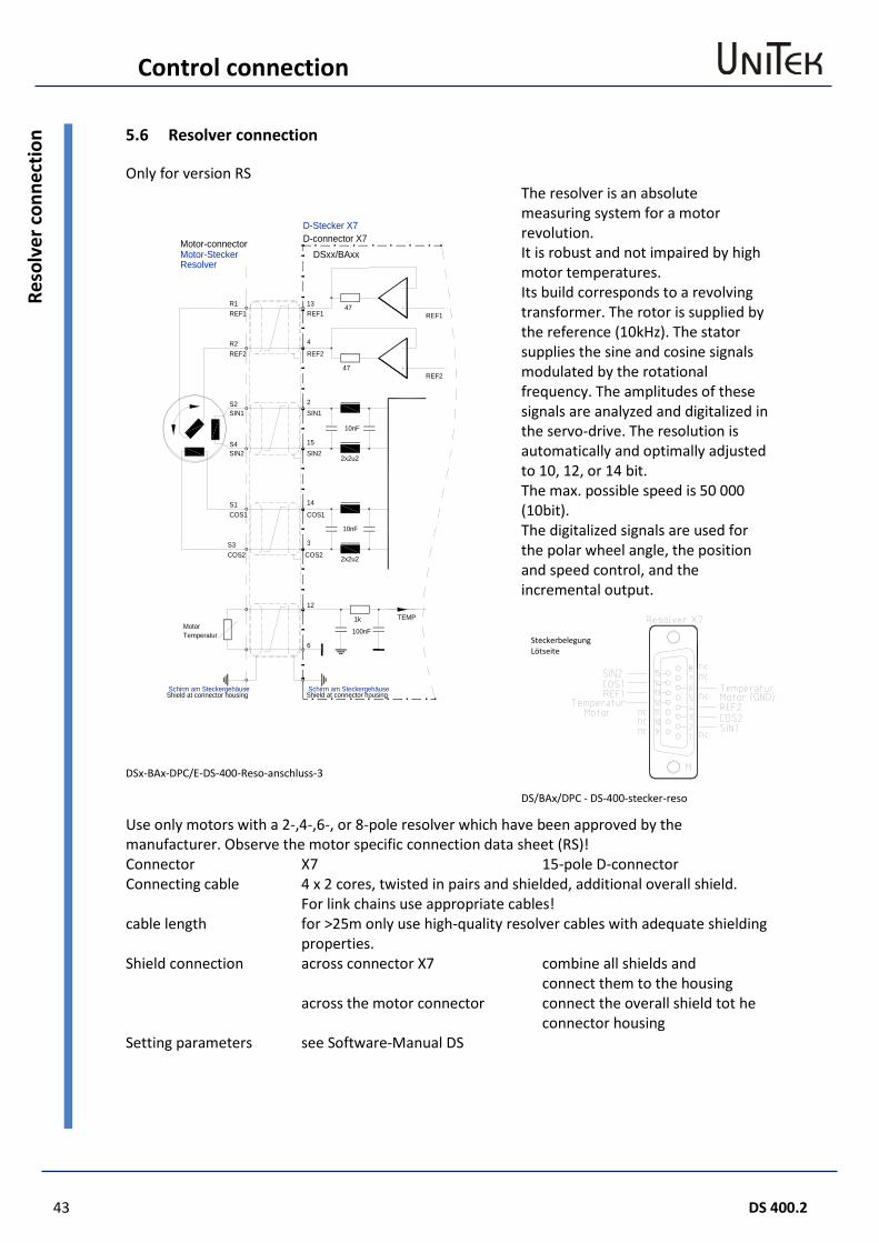
ion 5.6 Resolver connection
Only for version RS
DSx-BAx-DPC/E-DS-400-Reso-anschluss-3
The resolver is an absolute measuring system for a motor revolution. It is robust and not impaired by high motor temperatures. Its build corresponds to a revolving transformer. The rotor is supplied by the reference (10kHz). The stator supplies the sine and cosine signals modulated by the rotational frequency. The amplitudes of these signals are analyzed and digitalized in the servo-drive. The resolution is automatically and optimally adjusted to 10, 12, or 14 bit. The max. possible speed is 50 000 (10bit). The digitalized signals are used for the polar wheel angle, the position and speed control, and the incremental output. DS/BAx/DPC - DS-400-stecker-reso
Use only motors with a 2-,4-,6-, or 8-pole resolver which have been approved by the manufacturer. Observe the motor specific connection data sheet (RS)! Connector X7 15-pole D-connector Connecting cable 4 x 2 cores, twisted in pairs and shielded, additional overall shield.
For link chains use appropriate cables! cable length for >25m only use high-quality resolver cables with adequate shielding
properties. Shield connection across connector X7 combine all shields and
connect them to the housing across the motor connector connect the overall shield tot he
connector housing Setting parameters see Software-Manual DS
Steckerbelegung Lötseite
REF1
REF2
13
4
2
15
14
3
COS2
COS1
SIN1
SIN2
REF1
REF2
10nF
10nF
2x2u2
2x2u2
1k
100nF
47
47
TEMP
Motor-SteckerResolver
12
6
MotorTemperatur
REF1
REF2
SIN1
SIN2
COS1
COS2
R1
R2
S2
S4
S1
S3
DSxx/BAxx
Schirm am SteckergehäuseShield at connector housing
Schirm am SteckergehäuseShield at connector housing
Motor-connector
D-Stecker X7D-connector X7
Control connection
DS 400.2 44
Enco
der T
TL c
onne
ctio
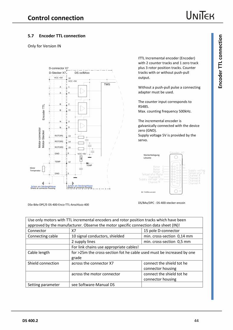
n 5.7 Encoder TTL connection
Only for Version IN
DSx-BAx-DPC/E-DS-400-Enco-TTL-Anschluss-400
ITTL Incremental encoder (Encoder) with 2 counter tracks and 1 zero track plus 3 rotor position tracks. Counter tracks with or without push-pull output. Without a push-pull pulse a connecting adapter must be used. The counter input corresponds to RS485. Max. counting frequency 500kHz. The incremental encoder is galvanically connected with the device zero (GND). Supply voltage 5V is provided by the servo.
DS/BAx/DPC - DS-400-stecker-encoin
Use only motors with TTL incremental encoders and rotor position tracks which have been approved by the manufacturer. Observe the motor specific connection data sheet (IN)! Connector X7 15 pole D-connector Connecting cable 10 signal conductors, shielded min. cross-section 0,14 mm 2 supply lines min. cross-section 0,5 mm For link chains use appropriate cables! Cable length for >25m the cross-section fot he cable used must be increased by one
grade Shield connection across the connector X7 connect the shield tot he
connector housing across the motor connector connect the shield tot he
connector housing Setting parameter see Software-Manual DS
Steckerbelegung Lötseite
M Sitftkontakt
TemperaturMotor
5
12
TEMP
Mot
or-S
teck
er
D-Stecker X7
TMS
Enc
oder
TTL
10VCC +5V
1A
4A
2B
11B
3N
9N
13ROTOR1
14ROTOR2
15ROTOR3
TEMP
6
DS xx/BAxxVCC +5V
GND
GND
4k7
VCC +5V
D-connector X7
Mot
or-c
onne
ctor
Schirm am SteckergehäuseShield at connector housingSchirm am Steckergehäuse
Shield at connector housing
45 DS 400.2
Control connection
Enco
der T
TL c
onne
ctio
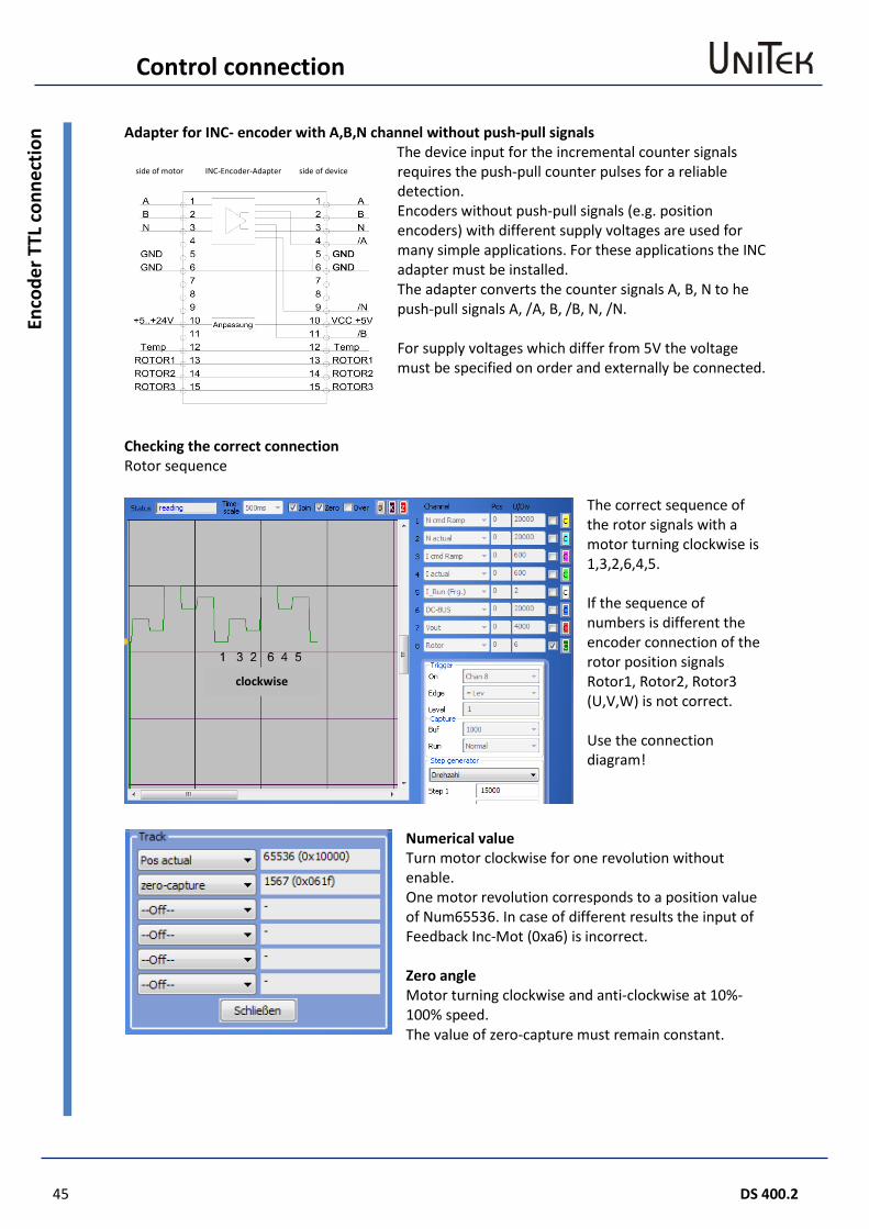
n Adapter for INC- encoder with A,B,N channel without push-pull signals The device input for the incremental counter signals
requires the push-pull counter pulses for a reliable detection. Encoders without push-pull signals (e.g. position encoders) with different supply voltages are used for many simple applications. For these applications the INC adapter must be installed. The adapter converts the counter signals A, B, N to he push-pull signals A, /A, B, /B, N, /N. For supply voltages which differ from 5V the voltage must be specified on order and externally be connected.
Checking the correct connection Rotor sequence
The correct sequence of the rotor signals with a motor turning clockwise is 1,3,2,6,4,5. If the sequence of numbers is different the encoder connection of the rotor position signals Rotor1, Rotor2, Rotor3 (U,V,W) is not correct. Use the connection diagram!
Numerical value Turn motor clockwise for one revolution without enable. One motor revolution corresponds to a position value of Num65536. In case of different results the input of Feedback Inc-Mot (0xa6) is incorrect. Zero angle Motor turning clockwise and anti-clockwise at 10%-100% speed. The value of zero-capture must remain constant.
clockwise
side of motor INC-Encoder-Adapter side of device
Control connection
DS 400.2 46
SIN
CO
S 1V
ss C
ON
NEC
TIO
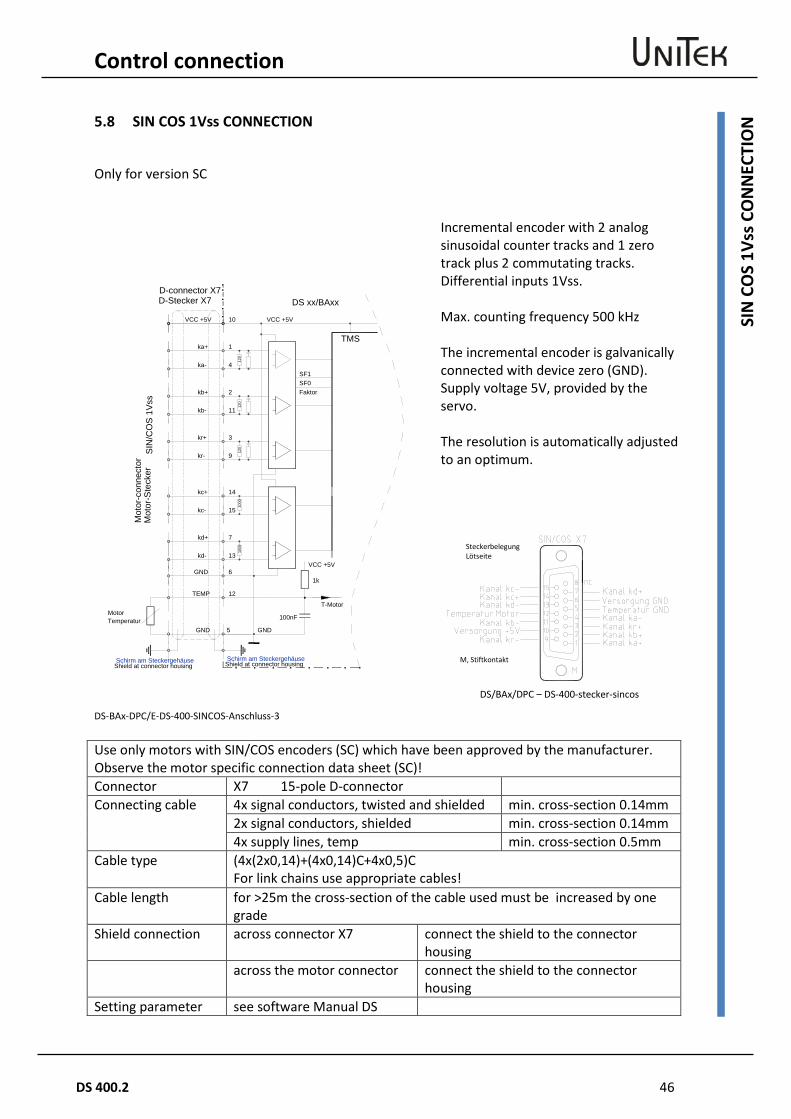
N 5.8 SIN COS 1Vss CONNECTION
Only for version SC
DS-BAx-DPC/E-DS-400-SINCOS-Anschluss-3
Incremental encoder with 2 analog sinusoidal counter tracks and 1 zero track plus 2 commutating tracks. Differential inputs 1Vss. Max. counting frequency 500 kHz The incremental encoder is galvanically connected with device zero (GND). Supply voltage 5V, provided by the servo. The resolution is automatically adjusted to an optimum.
DS/BAx/DPC – DS-400-stecker-sincos
Use only motors with SIN/COS encoders (SC) which have been approved by the manufacturer. Observe the motor specific connection data sheet (SC)! Connector X7 15-pole D-connector Connecting cable 4x signal conductors, twisted and shielded min. cross-section 0.14mm
2x signal conductors, shielded min. cross-section 0.14mm 4x supply lines, temp min. cross-section 0.5mm
Cable type (4x(2x0,14)+(4x0,14)C+4x0,5)C For link chains use appropriate cables!
Cable length for >25m the cross-section of the cable used must be increased by one grade
Shield connection across connector X7 connect the shield to the connector housing
across the motor connector connect the shield to the connector housing
Setting parameter see software Manual DS
Steckerbelegung Lötseite
M, Stiftkontakt
TemperaturMotor
100nF
5
12
T-Motor
Mot
or-S
teck
er
D-Stecker X7
TMS
SIN
/CO
S 1V
ss
10 VCC +5V
1ka+
4ka-
TEMP
DS xx/BAxx
120
2kb+
11kb-
120
3kr+
9kr-
120
14kc+
15kc-
1000
7kd+
13kd-
1000
1k
VCC +5V
GND
6
VCC +5V
GND
GND
SF1SF0Faktor
D-connector X7
Mot
or-c
onne
ctor
Schirm am SteckergehäuseShield at connector housingSchirm am Steckergehäuse
Shield at connector housing
47 DS 400.2
Control connection
Roto
r pos
ition
enc
oder
– c
onne
ctio
n vi
a a
bl-t
acho
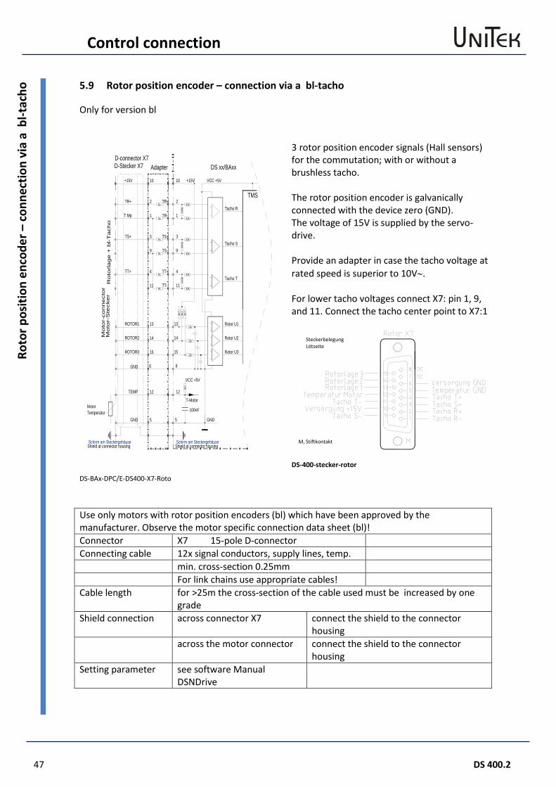
5.9 Rotor position encoder – connection via a bl-tacho
Only for version bl
3 rotor position encoder signals (Hall sensors) for the commutation; with or without a brushless tacho. The rotor position encoder is galvanically connected with the device zero (GND). The voltage of 15V is supplied by the servo-drive. Provide an adapter in case the tacho voltage at rated speed is superior to 10V∼. For lower tacho voltages connect X7: pin 1, 9, and 11. Connect the tacho center point to X7:1
DS-400-stecker-rotor
DS-BAx-DPC/E-DS400-X7-Roto Use only motors with rotor position encoders (bl) which have been approved by the manufacturer. Observe the motor specific connection data sheet (bl)! Connector X7 15-pole D-connector Connecting cable 12x signal conductors, supply lines, temp. min. cross-section 0.25mm For link chains use appropriate cables! Cable length for >25m the cross-section of the cable used must be increased by one
grade Shield connection across connector X7 connect the shield to the connector
housing across the motor connector connect the shield to the connector
housing Setting parameter see software Manual
DSNDrive
Steckerbelegung Lötseite
M, Stiftkontakt
13ROTOR1
14ROTOR2
15ROTOR3
6
TemperaturMotor
100nF
5
12
T-Motor
Mo
tor-
Ste
cker
D-Stecker X7
TMS
Ro
torl
ag
e +
bl-T
acho
10 VCC +5V
2TR+
1T Mp
TEMP
DS xx/BAxx
100k
3TS+
9
100k
4TT+
11
100k
GND
+15V
GND
82k
82k
82k
82k
82k
82k
Tacho R
Tacho S
Tacho T
4k7
4k7
4k7
22k
22k
22k
4k7
Rotor U1
Rotor U2
Rotor U3
GND
VCC +5V
+15V
Rv
Rv
Rv
Rv
Rv
Rv
TR+
TR-
TS+
TS-
TT+
TT-
Adapter
13
14
15
6
5
12
10
2
1
3
9
4
11
D-connector X7
Mo
tor-
co
nnecto
r
Schirm am SteckergehäuseShield at connector housing
Schirm am SteckergehäuseShield at connector housing
Control connection
DS 400.2 48
X8 T
TL-E
ncod
er o
utpu
t or i
nput
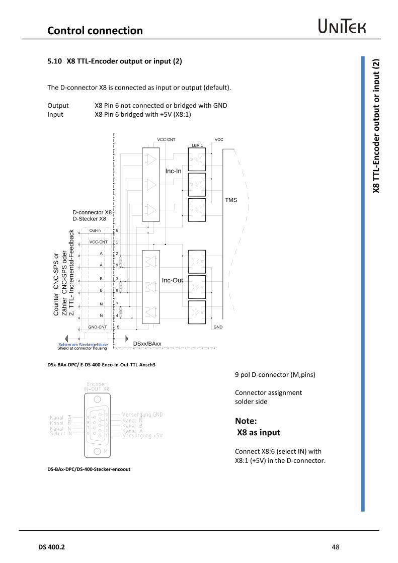
(2) 5.10 X8 TTL-Encoder output or input (2)
The D-connector X8 is connected as input or output (default). Output X8 Pin 6 not connected or bridged with GND Input X8 Pin 6 bridged with +5V (X8:1)
DSx-BAx-DPC/ E-DS-400-Enco-In-Out-TTL-Ansch3
DS-BAx-DPC/DS-400-Stecker-encoout
D-Stecker X8
1VCC-CNT
2
9
3
8
7
4
5GND-CNT
TMS
DSxx/BAxx
6Out-In
A
A
B
B
N
N
VCC-CNT
GND
LBR 1
Inc-In
Inc-Out
Zähl
er C
NC
-SP
S o
der
2. T
TL- I
ncre
men
tal-F
eedb
ack
VCC
470
470
470
Schirm am SteckergehäuseShield at connector housing
D-connector X8
Cou
nter
CN
C-S
PS
or
9 pol D-connector (M,pins) Connector assignment solder side Note: X8 as input Connect X8:6 (select IN) with X8:1 (+5V) in the D-connector.
49 DS 400.2
Control connection
X8 a
s TTL
Enc
oder
out
put 5.11 X8 as TTL Encoder output
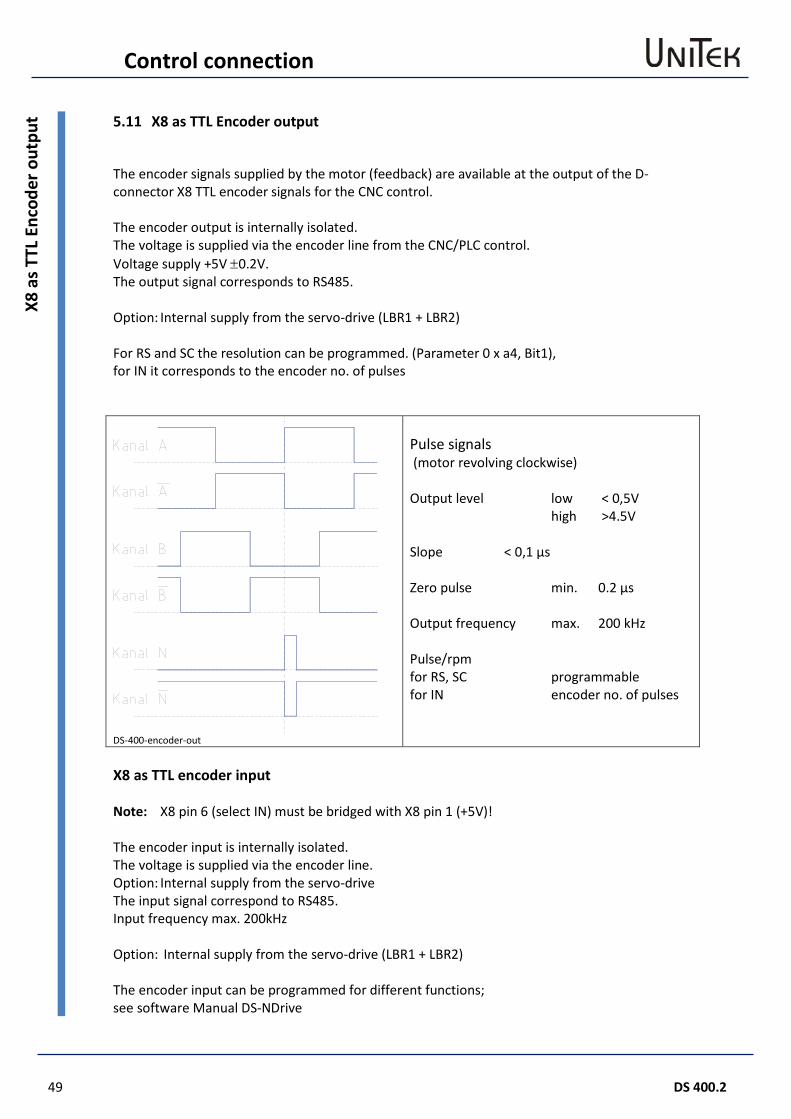
The encoder signals supplied by the motor (feedback) are available at the output of the D-connector X8 TTL encoder signals for the CNC control. The encoder output is internally isolated. The voltage is supplied via the encoder line from the CNC/PLC control. Voltage supply +5V ±0.2V. The output signal corresponds to RS485. Option: Internal supply from the servo-drive (LBR1 + LBR2) For RS and SC the resolution can be programmed. (Parameter 0 x a4, Bit1), for IN it corresponds to the encoder no. of pulses
DS-400-encoder-out
Pulse signals (motor revolving clockwise) Output level low < 0,5V high >4.5V Slope < 0,1 µs Zero pulse min. 0.2 µs Output frequency max. 200 kHz Pulse/rpm for RS, SC programmable for IN encoder no. of pulses
X8 as TTL encoder input Note: X8 pin 6 (select IN) must be bridged with X8 pin 1 (+5V)! The encoder input is internally isolated. The voltage is supplied via the encoder line. Option: Internal supply from the servo-drive The input signal correspond to RS485. Input frequency max. 200kHz Option: Internal supply from the servo-drive (LBR1 + LBR2) The encoder input can be programmed for different functions; see software Manual DS-NDrive
Control connection
DS 400.2 50
Dis
play
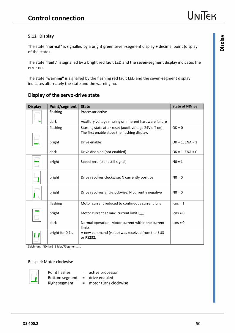
5.12 Display
The state "normal" is signalled by a bright green seven-segment display + decimal point (display of the state). The state "fault" is signalled by a bright red fault LED and the seven-segment display indicates the error no. The state "warning" is signalled by the flashing red fault LED and the seven-segment display indicates alternately the state and the warning no. Display of the servo-drive state Display Point/segment State State of NDrive
flashing dark
Processor active Auxiliary voltage missing or inherent hardware failure
flashing bright dark
Starting state after reset (auxil. voltage 24V off-on). The first enable stops the flashing display. Drive enable Drive disabled (not enabled)
OK = 0 OK = 1, ENA = 1 OK = 1, ENA = 0
bright
Speed zero (standstill signal)
N0 = 1
bright
Drive revolves clockwise, N currently positive
N0 = 0
bright
Drive revolves anti-clockwise, N currently negative
N0 = 0
flashing bright dark
Motor current reduced to continuous current Icns Motor current at max. current limit Imax
Normal operation; Motor current within the current limits
Icns = 1 Icns = 0 Icns = 0
bright for 0.1 s A new command (value) was received from the BUS or RS232.
Zeichnung_NDrive2_Bilder/7Segment…… Beispiel: Motor clockwise
Point flashes
=
active processor
Bottom segment Right segment
= =
drive enabled motor turns clockwise
51 DS 400.2
Control connection
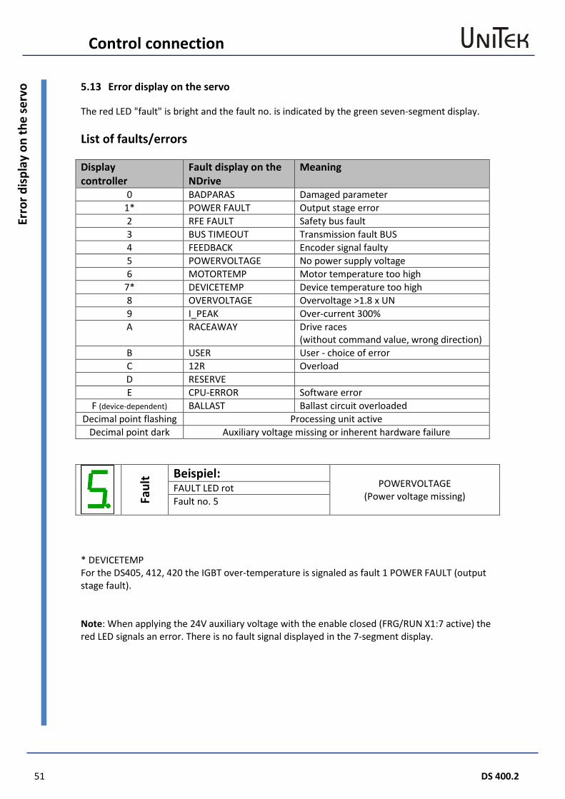
Erro
r dis
play
on
the
serv
o 5.13 Error display on the servo
The red LED "fault" is bright and the fault no. is indicated by the green seven-segment display. List of faults/errors Display controller
Fault display on the NDrive
Meaning
0 BADPARAS Damaged parameter 1* POWER FAULT Output stage error 2 RFE FAULT Safety bus fault 3 BUS TIMEOUT Transmission fault BUS 4 FEEDBACK Encoder signal faulty 5 POWERVOLTAGE No power supply voltage 6 MOTORTEMP Motor temperature too high
7* DEVICETEMP Device temperature too high 8 OVERVOLTAGE Overvoltage >1.8 x UN 9 I_PEAK Over-current 300% A RACEAWAY Drive races
(without command value, wrong direction) B USER User - choice of error C 12R Overload D RESERVE E CPU-ERROR Software error
F (device-dependent) BALLAST Ballast circuit overloaded Decimal point flashing Processing unit active
Decimal point dark Auxiliary voltage missing or inherent hardware failure
Faul
t Beispiel: POWERVOLTAGE
(Power voltage missing) FAULT LED rot Fault no. 5
* DEVICETEMP For the DS405, 412, 420 the IGBT over-temperature is signaled as fault 1 POWER FAULT (output stage fault). Note: When applying the 24V auxiliary voltage with the enable closed (FRG/RUN X1:7 active) the red LED signals an error. There is no fault signal displayed in the 7-segment display.
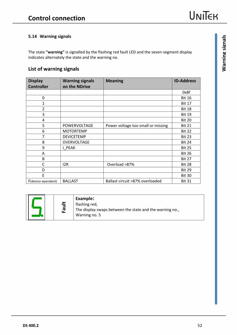
Control connection
DS 400.2 52
War
ning
sign
als 5.14 Warning signals
The state "warning" is signalled by the flashing red fault LED and the seven-segment display indicates alternately the state and the warning no. List of warning signals Display Controller
Warning signals on the NDrive
Meaning ID-Address
0x8f 0 Bit 16 1 Bit 17 2 Bit 18 3 Bit 19 4 Bit 20 5 POWERVOLTAGE Power voltage too small or missing Bit 21 6 MOTORTEMP Bit 22 7 DEVICETEMP Bit 23 8 OVERVOLTAGE Bit 24 9 I_PEAK Bit 25 A Bit 26 B Bit 27 C I2R Overload >87% Bit 28 D Bit 29 E Bit 30
F(device-ependent) BALLAST Ballast circuit >87% overloaded Bit 31
Faul
t Example: flashing red, The display swaps between the state and the warning no., Warning no. 5
53 DS 400.2
Warranty
War
rant
y 6 Warranty
6.1 Warranty
UNITEK warranties that the device is free from material and production defects. Test results are recorded and archived with the serial number. The warranty time begins from the time the device is shipped, and lasts two years. UNITEK undertakes no warranties for devices which have been modified for special applications. During the warranty period, UNITEK will, at its option, either repair or replace products that prove to be defective, this includes guaranteed functional attributes. UNITEK specifically disclaims the implied warranties or merchantability and fitness for a particular purpose. For warranty service or repair, this product must be returned to a service facility designated by UNITEK. For products returned to UNITEK for warranty service, the buyer shall prepay shipping charges to UNITEK and UNITEK shall pay shipping charges to return the product to the buyer. However, the buyer shall pay all shipping charges, duties and taxes for products returned to UNITEK from another country. The foregoing warranty shall not apply to defects resulting from: - improper or inadequate repairs effected by the buyer or a third party, - non-observance of the manual which is included in all consignments, - non-observance of the electrical standards and regulations, - improper maintenance - acts of nature. All further claims on transformation, diminution and replacement of any kind of damage, especially damage, which does not affect the UNITEK device, cannot be considered. Follow-on damage within the machine or system, which may arise due to malfunction or defect in the device cannot be claimed. This limitation does not affect the product liability laws as applied in the place of manufacture (i.e. Germany). UNITEK reserves the right to change any information included this MANUAL. All connection circuitry described is meant for general information purposes and is not mandatory. The local legal regulations, and those of the standards authorities have to be adhered to. UNITEK does not assume any liability, expressively or inherently, for the information contained in this MANUAL, for the functioning of the device or its suitability for any specific application. All rights are reserved. Copying, modifying and translations lie outside UNITEK’s liability and thus are not prohibited. UNITEK’s products are not authorised for use as critical components in the life support devices or systems without express written approval. The onus is on the reader to verify that the information here is current